G.L.
-
Posts
1,553 -
Joined
-
Last visited
Content Type
Profiles
Forums
Gallery
Events
Everything posted by G.L.
-
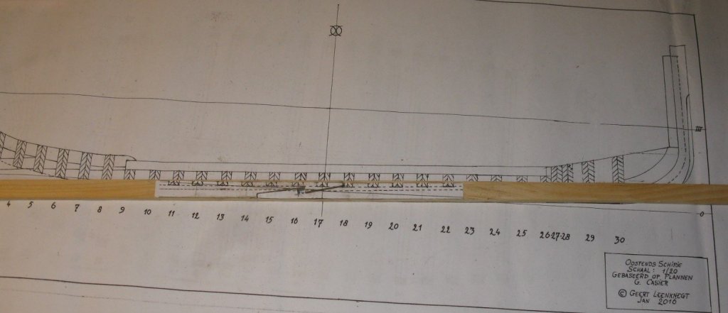
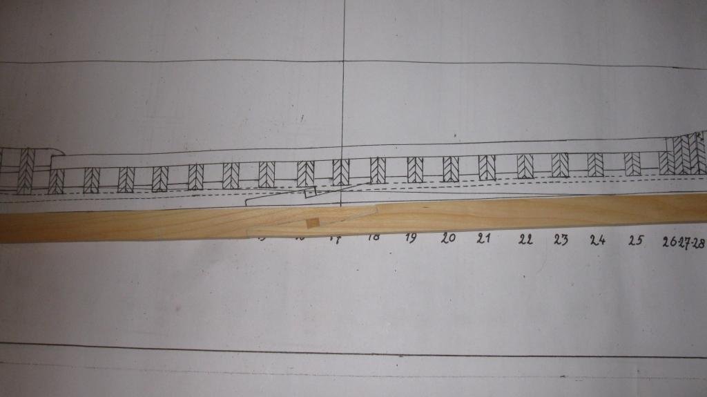
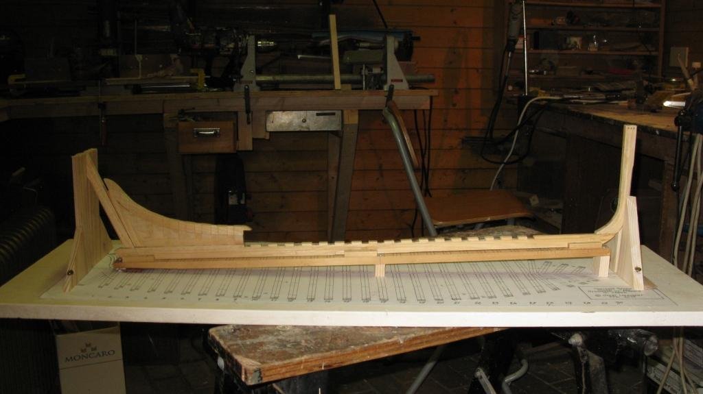
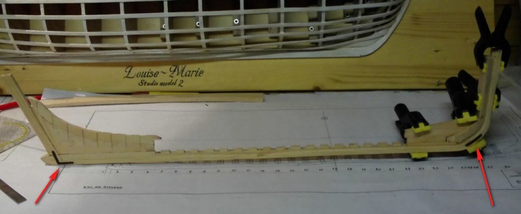
 5.3 Starting to place the square frames.
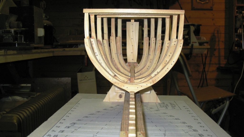
-
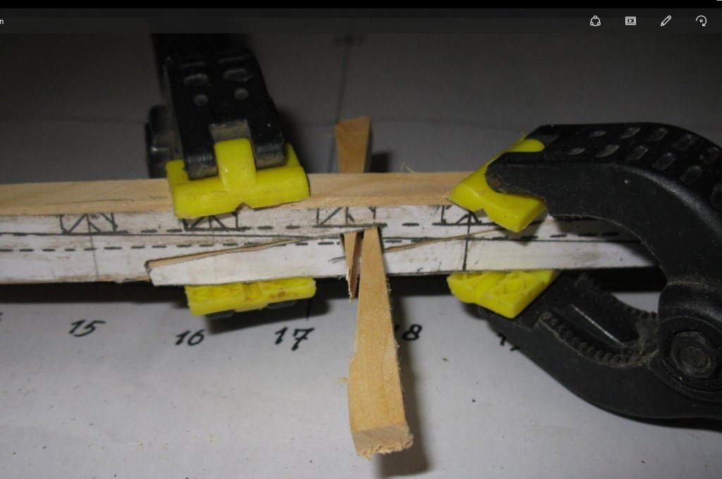
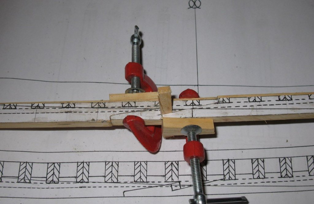
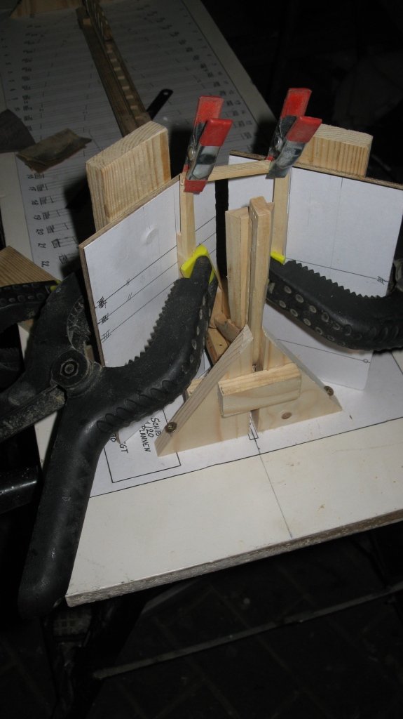
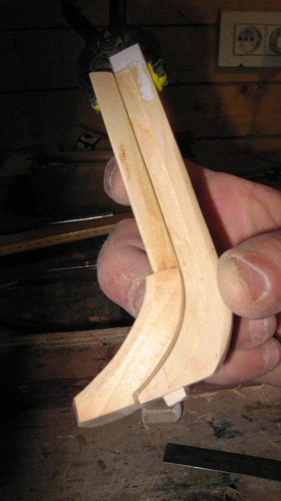
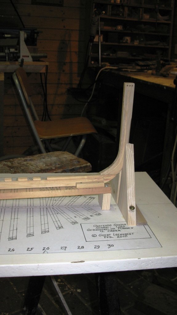
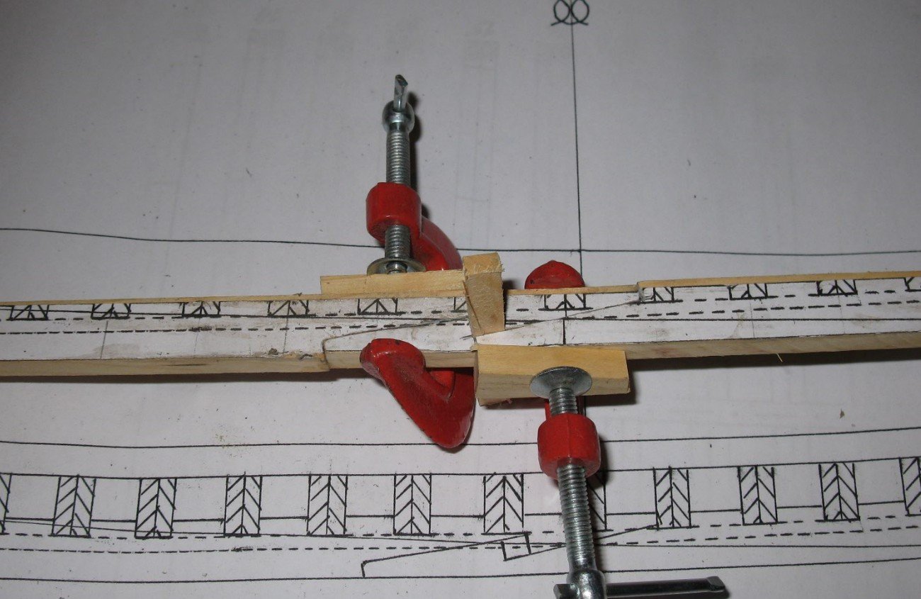
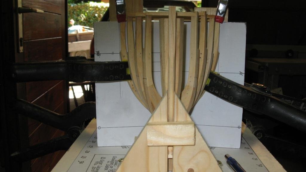
5.2 The four cant frames are in place. I make the ends of the frames a bit longer than needed, they can be sawn to measure later. I glue a small lath between the two frame ends to prevent deformation.
-
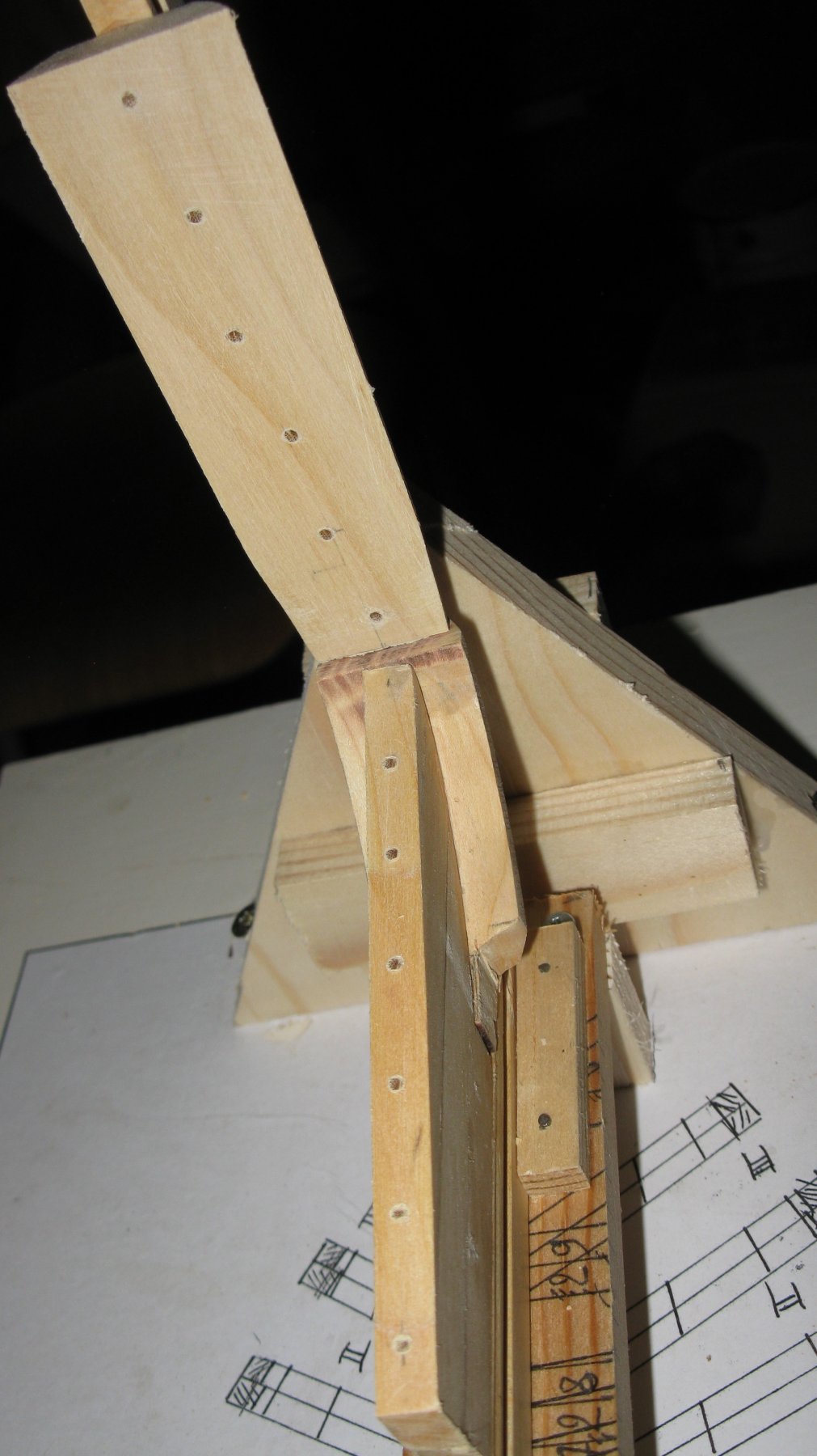
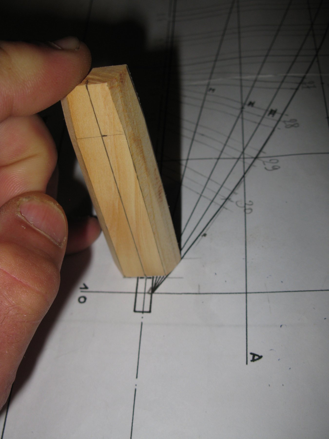
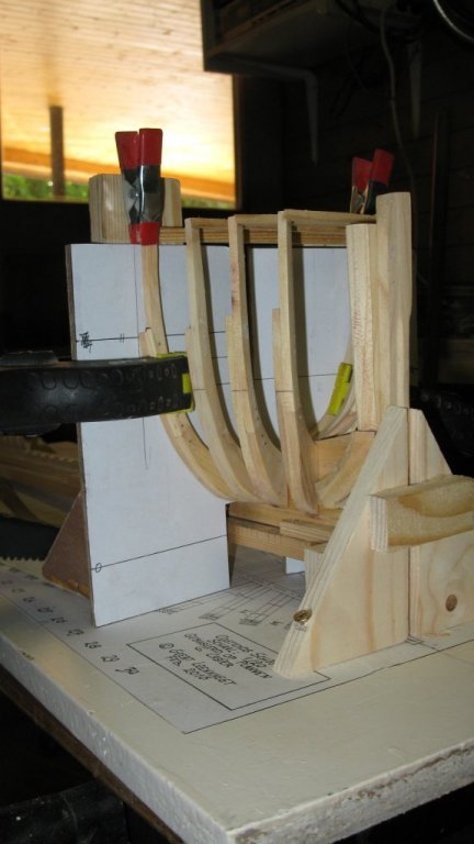
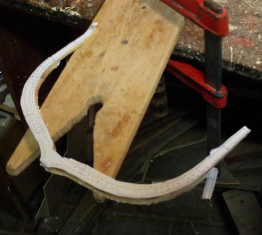
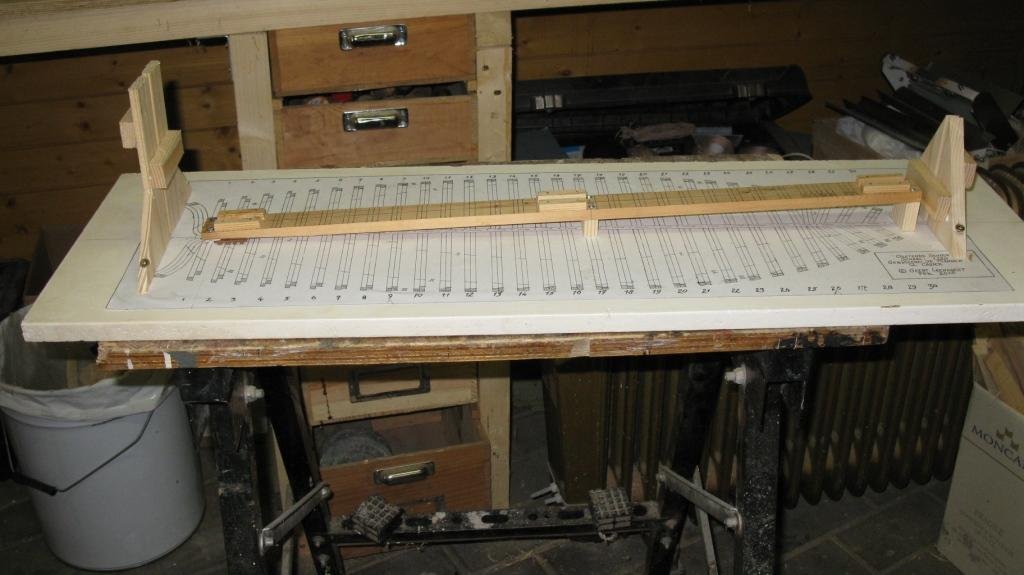
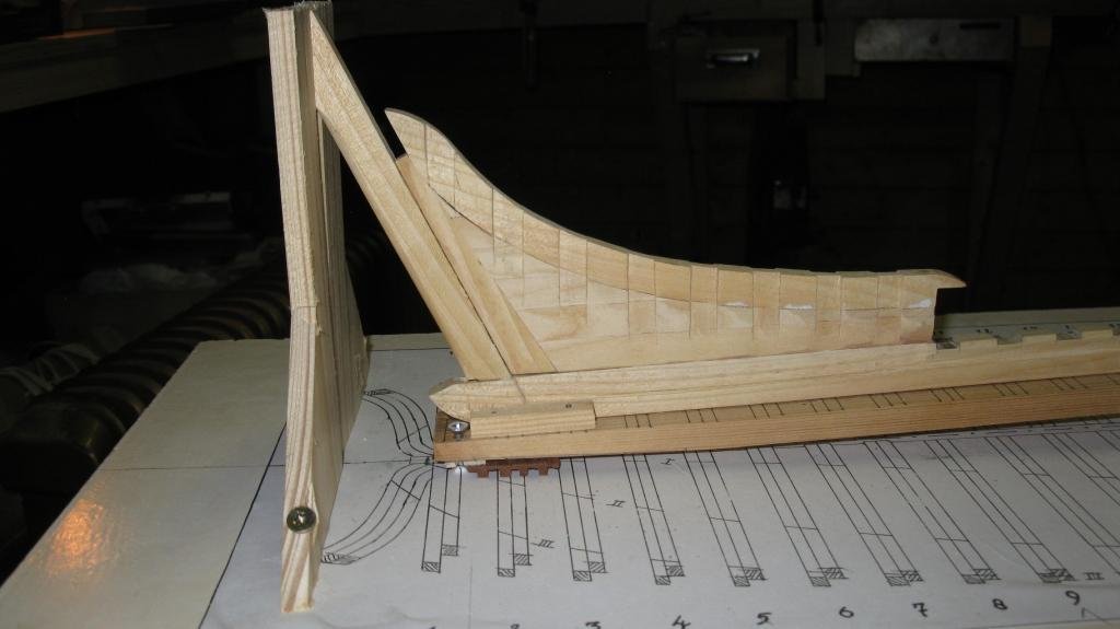
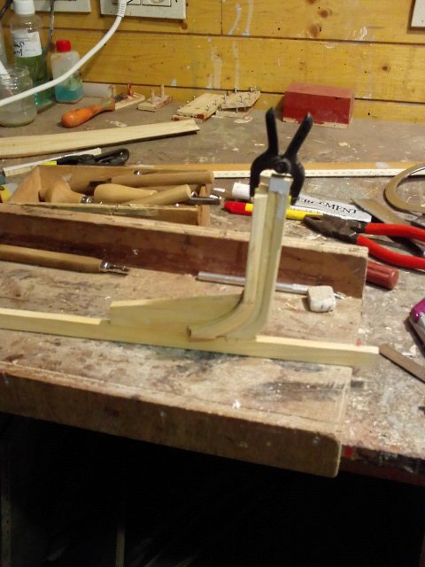
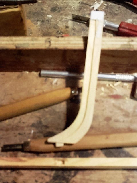
Part 5: Placing the frames 5.1 The forward frames are cant frames. The angle with the keel is different for each of the four frames. To glue them in place I made two supports which have to be lined up with the frame plan.

-
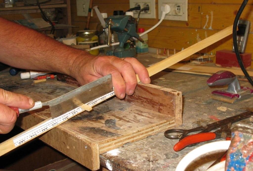
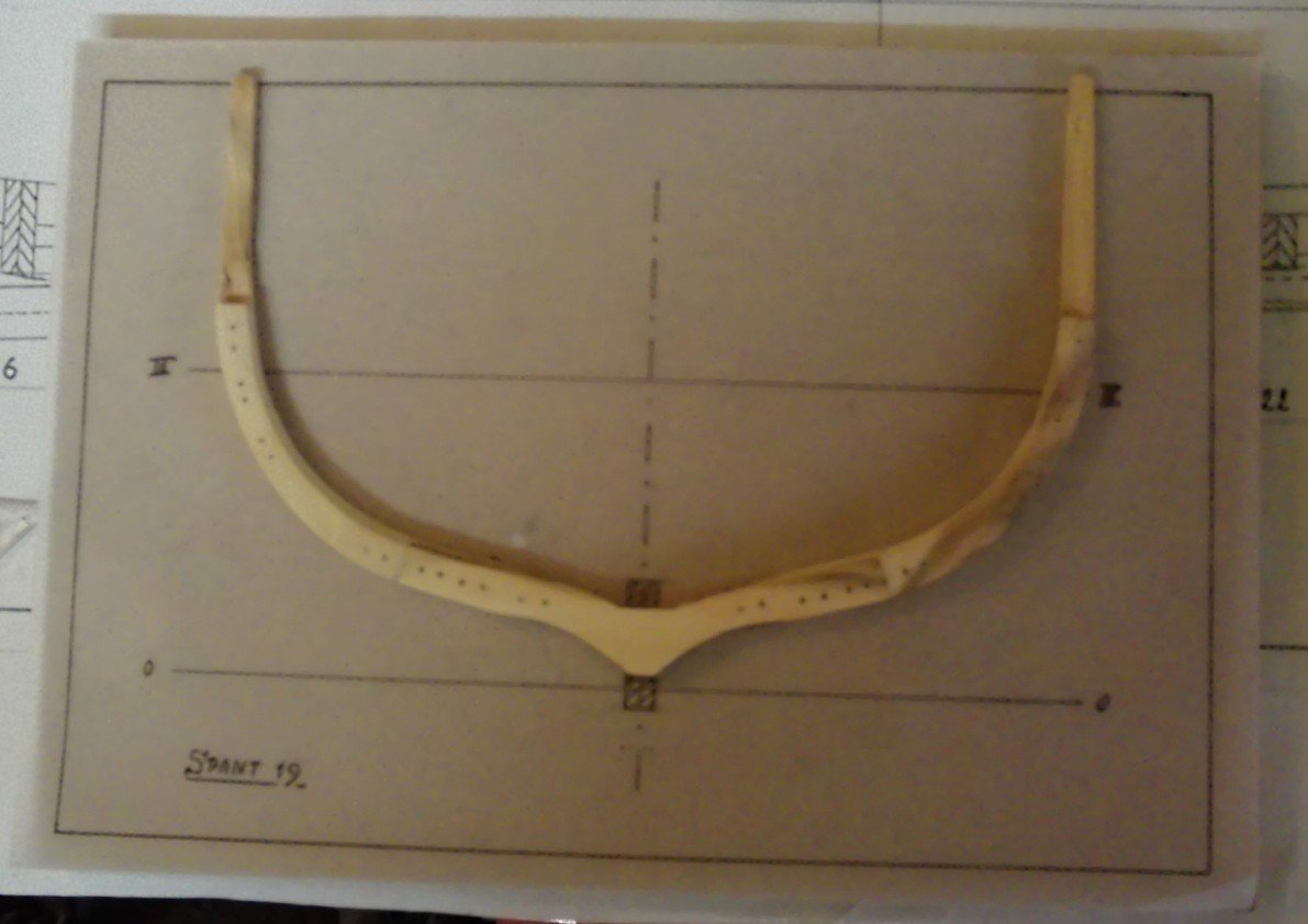
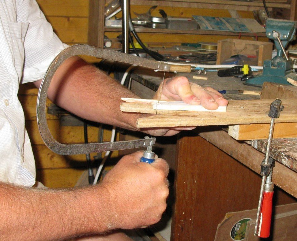
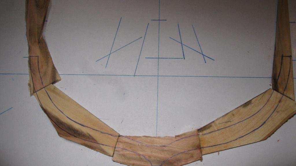
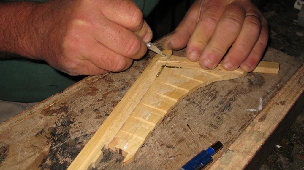
4.3 I have made a wooden box of which the inner dimensions are the sizes of an A4 paper. The paper with the glued frame parts fits in it. On top of the wooden frame parts I glue the original frame plan and cover the hole with a plank of A4 size and lay some lead weights on it. There is space for three frames in the box. Next day I have a strongly glued piece with the frame drawing on both sides which make it easy to saw the frame and to sand the sides and the bevels with the drum sander. After being sanded, I treenail the frame.

-
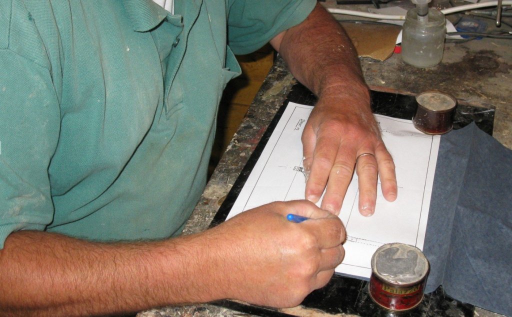
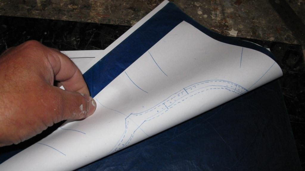
Now I know where to glue the pieces of the second layer and to make sure that I have an overlap along the whole frame.
-
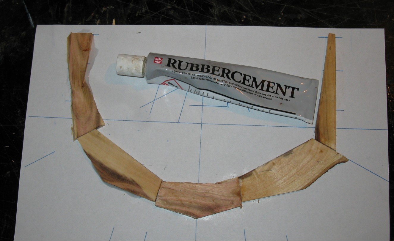
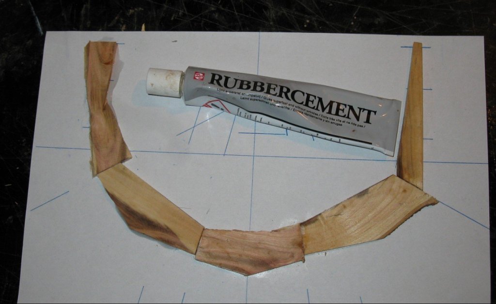
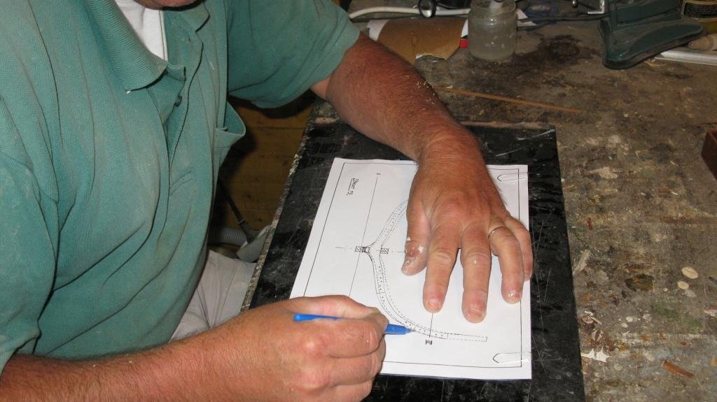
4.2 I use the carbon copy to glue the first layer of the frame on with rubber cement. Between the joints of wood pieces I put wood glue. On that layer I lay once again a carbon paper and exactly on top the frame drawing and press trough the outline of the frame. This time the copy is made on the wooden layer.
-
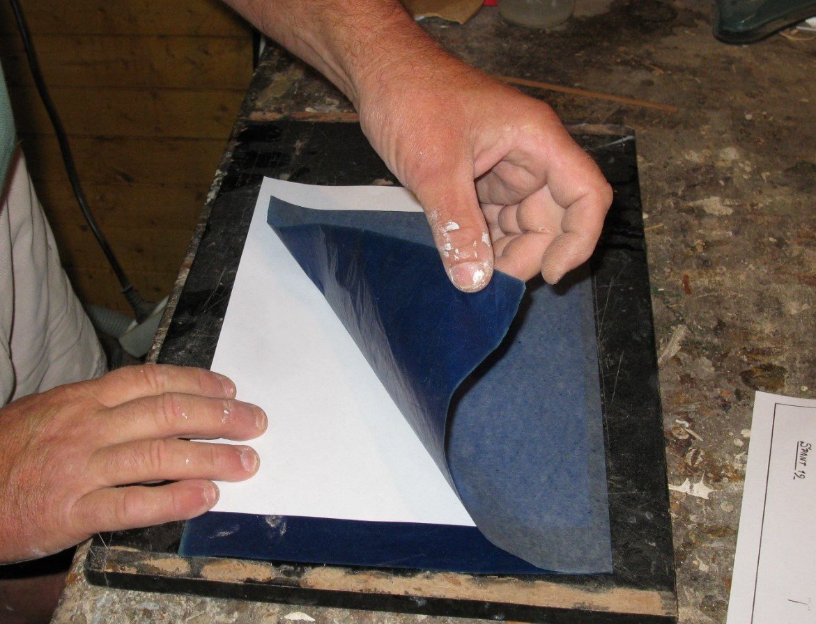
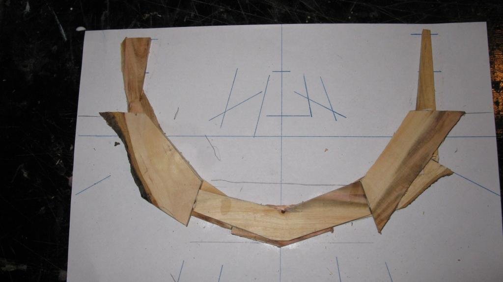
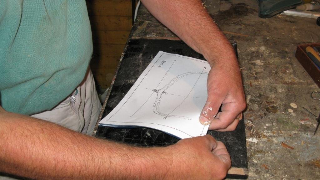
Part 4: Making the frames 4.1 I can start to make frames. I must make thirty frames, that can take a while. The frames of a Flemish fishing vessel ware made in two layers with some eight to eleven different pieces of oak. I will try to explain my method. Probably there will be other and better ways, but this method suits me. I first lay a A4 format paper between two layers of carbon paper (typewriter era) in such a way that both sides of the paper touch a carbon side. Then I lay the frame drawing (also A4 format) on it and take care that the two papers are exactly on top of each other. When that is done I press trough the frame drawing with a fine embossing pen. The result is a copy of the frame drawing on both sides of the paper.


-
Thank You Nils.
-
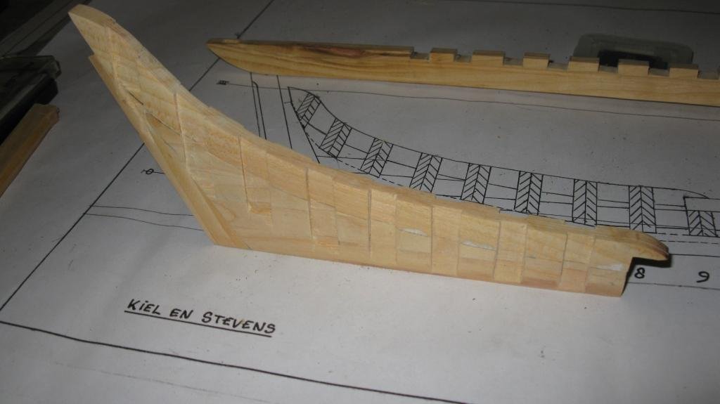
3.18 The assembly of keel, stem and stern can now be placed on the 'slipway'. A shrimper was down at the stern, therefore the slipway has a downward slope towards the after end. On the second picture the stem is not yet completely assembled and the irons are not yet in place.
-
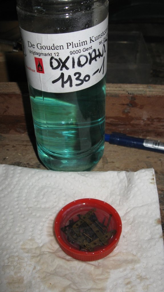
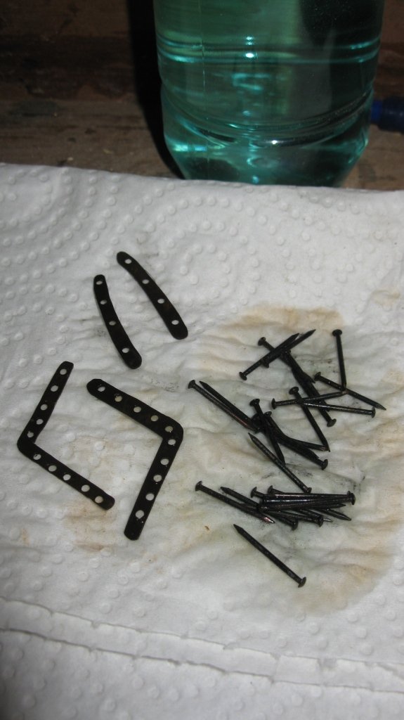
3.17 The irons are blackened with a brass oxidant and fastened on the model with brass nails.


-
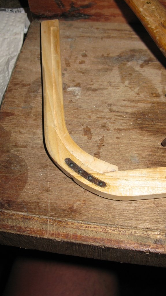
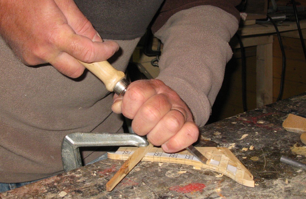
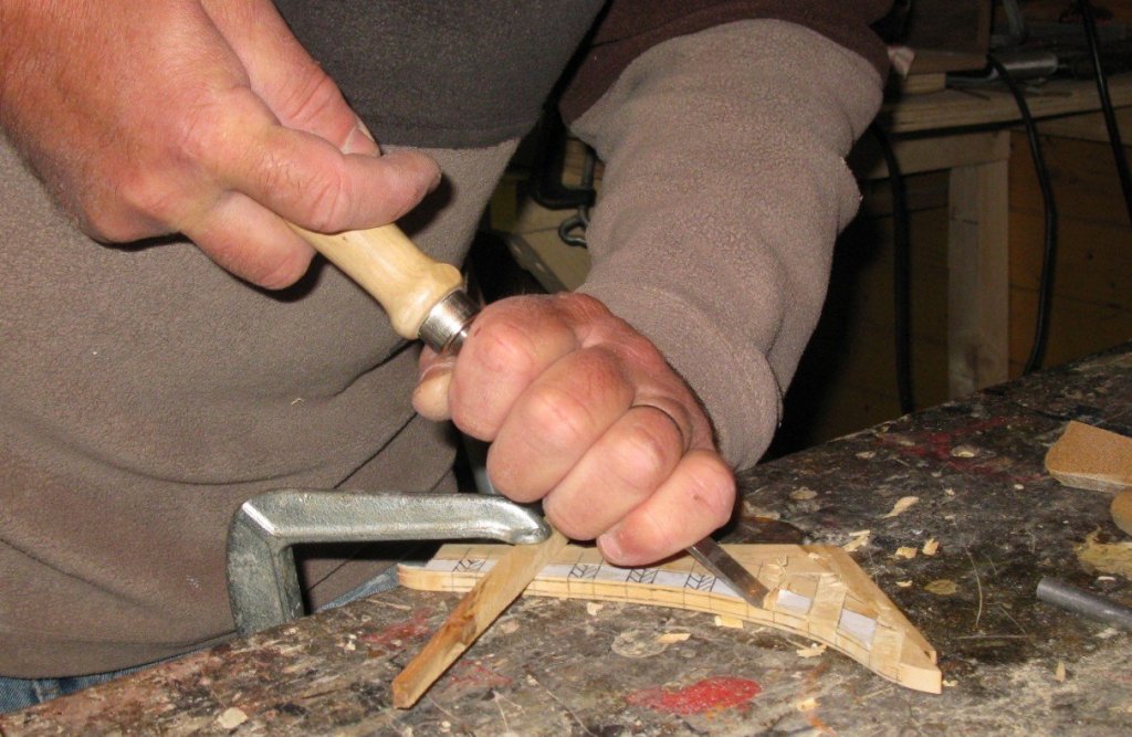
3.16 Carving the slots for the irons.
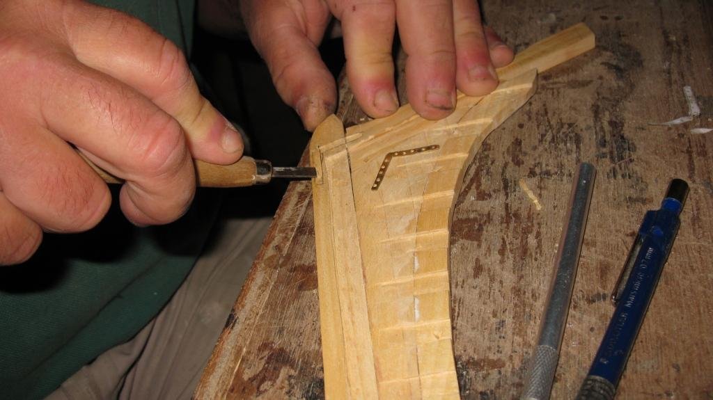
-
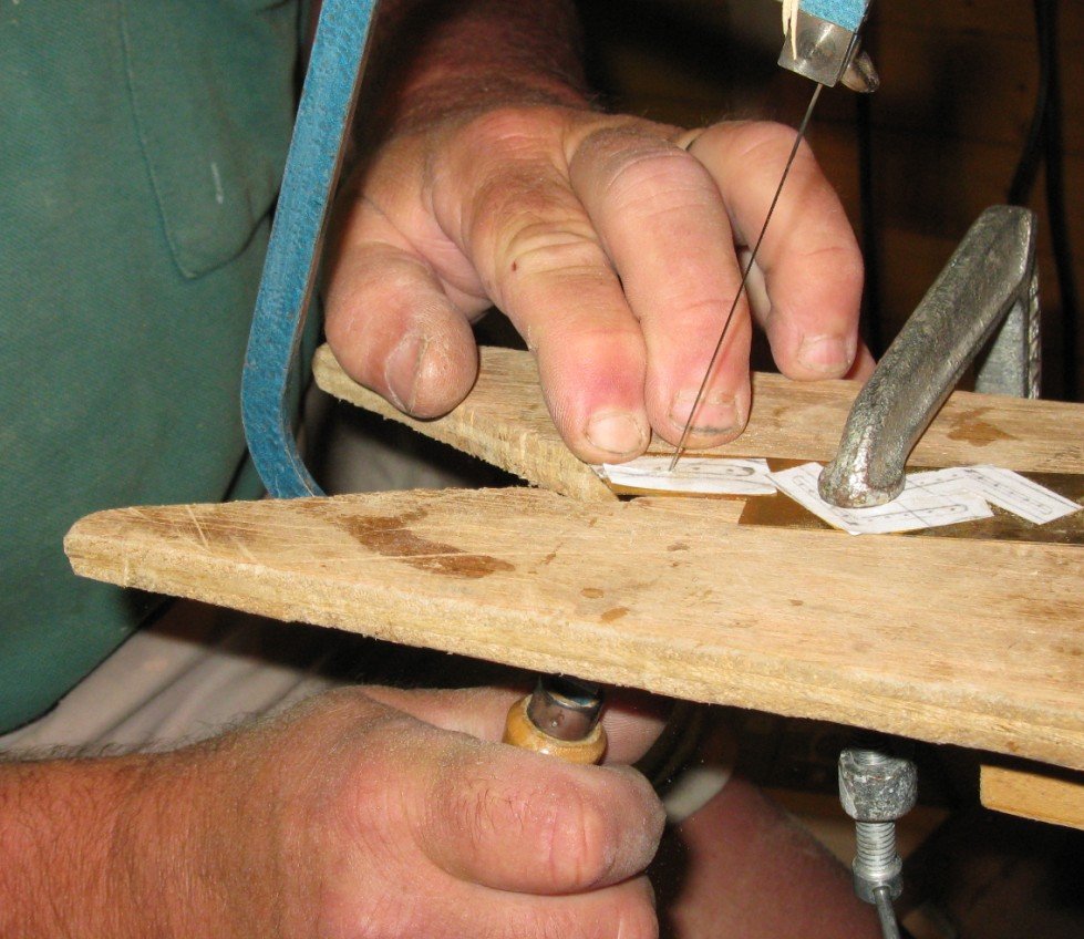
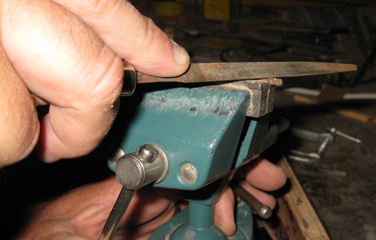
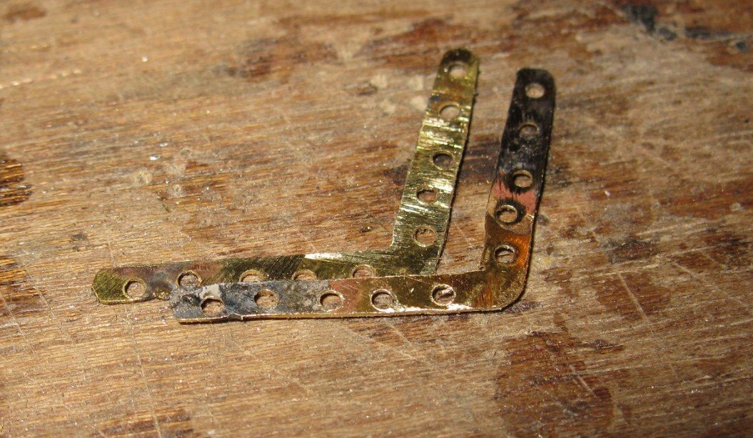
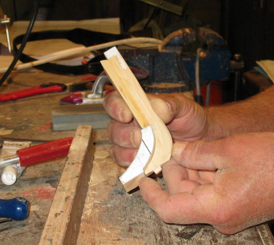
3.15 The sternpost and the stem are consolidated on the keel with steel straps. I do not know the term in English. I make them from a plate of brass. I am not used to work with metal. I sawed the pieces with the fret saw. The stem pieces are curved and the stern pieces in a hooked shape. To obtain identical couples of straps I solder them together before filing them. After being filed they can be loosed from each other by heating the soldering.

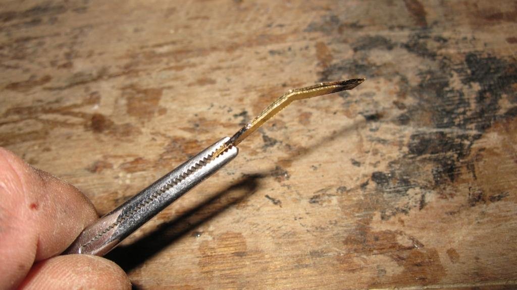


-
3.14 The sternpost and the stern timbers and deadwood are made in the same way as the forward parts. Grooves have to be made in the deadwood to place the 8 half frames.
-
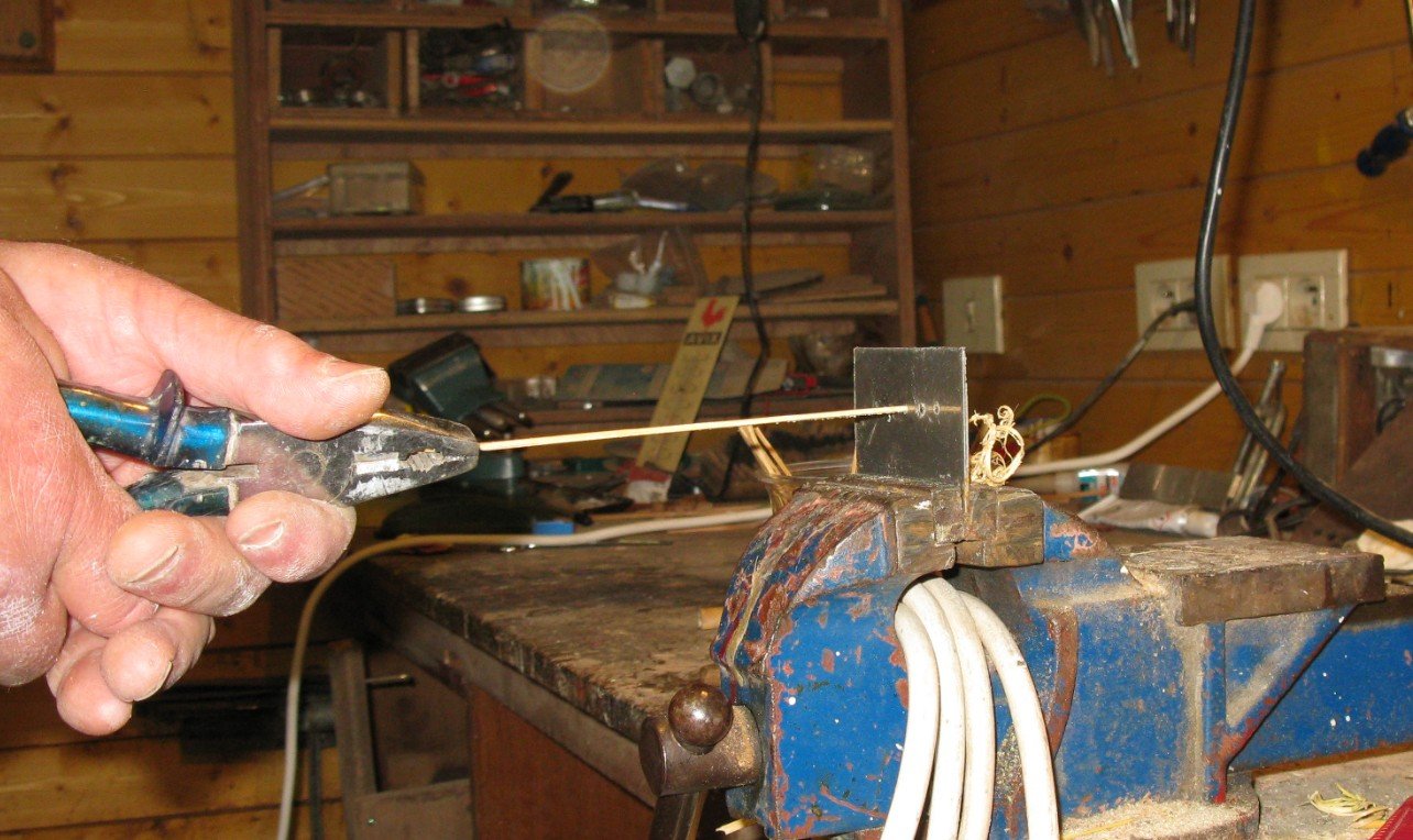
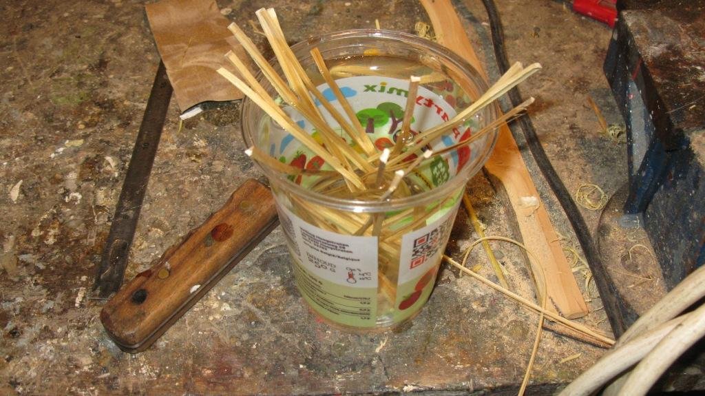
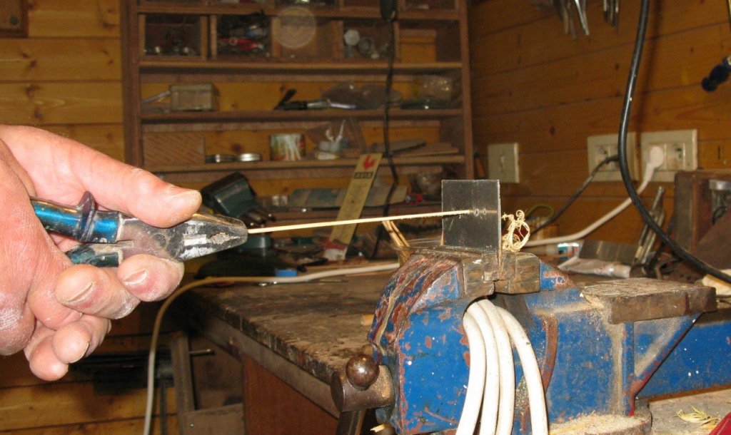
3.13 I soak the sticks for a while in water (± 30 min) and then pull them through the successive holes in the plate until the desired diameter is reached.
-
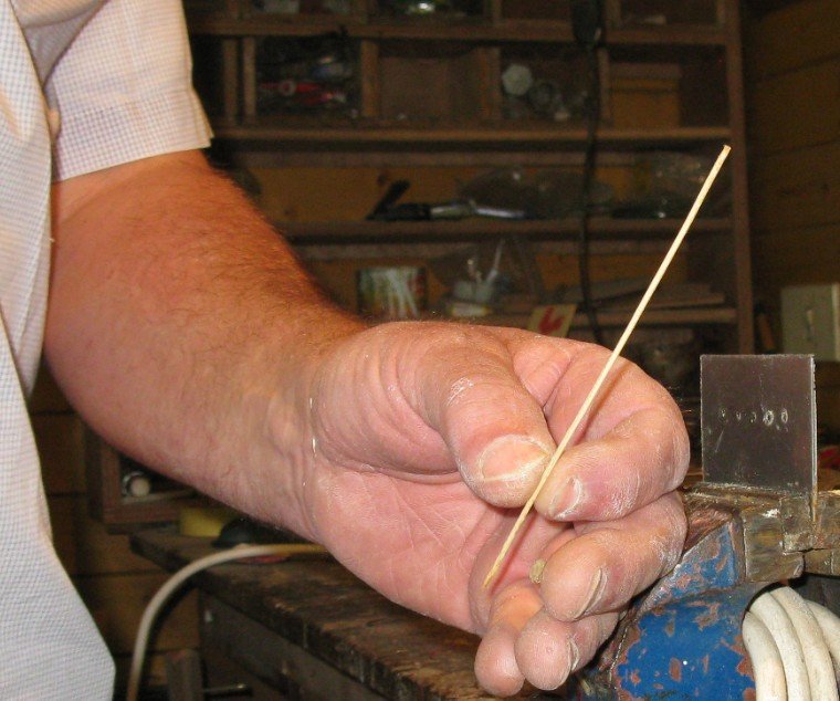
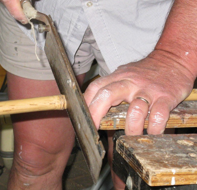
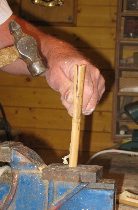
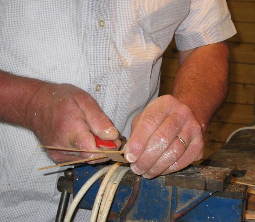
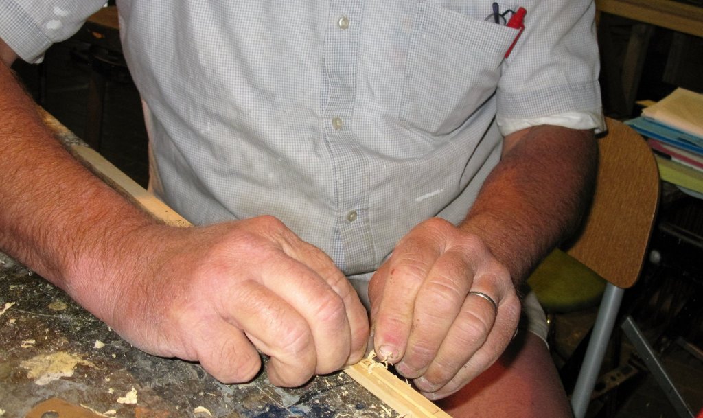
3.12 I wait until the cut off stems become yellow (takes some months) and saw them between the knuckles into hollow pipes. The pipes can be split easily into sticks with a knife. A little tic on the knife with a hammer may help. Split the sticks further as close as possible to the needed diameter for the treenail.
-
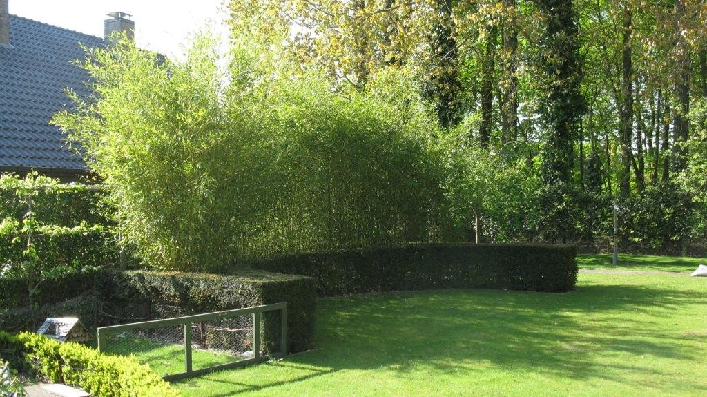
3.11 The treenails are made with bamboo from our garden.
-
3.10 The last thing to do is gluing the whole assembly together and fixing the deadwood with the keel and the apron with the stem with treenails.

-
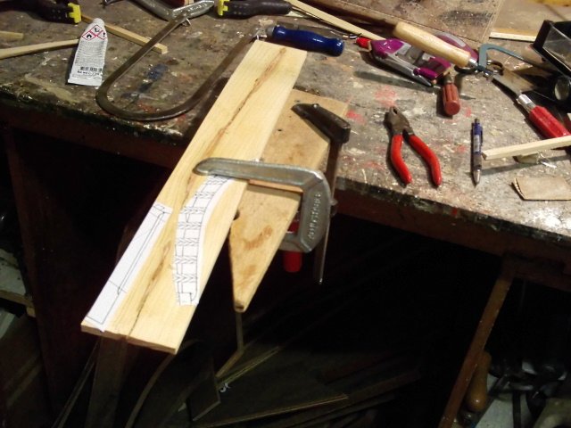
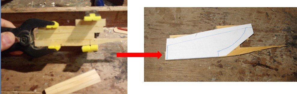
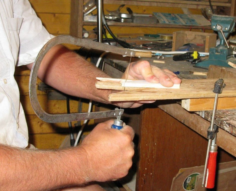
3.9 For the forward deadwood I glue four oversized planks on each other. On top of it I glue with rubber-cement a paper with the shape of the deadwood. I saw the deadwood with the fretsaw.
-
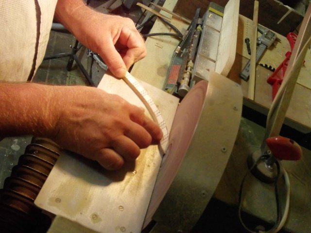
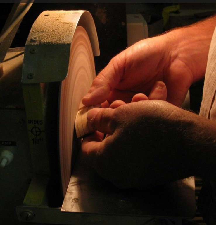
3.8 Determining the shape of the knee is a little more difficult as for the apron because the knee is round. I take for the upper shape the lower profile of the apron and for the after shape the profile of the first station. I use the sand disk to give the knee shape mostly at random between the two profiles.

-
3.7 I saw the stem knee out of a block.

-
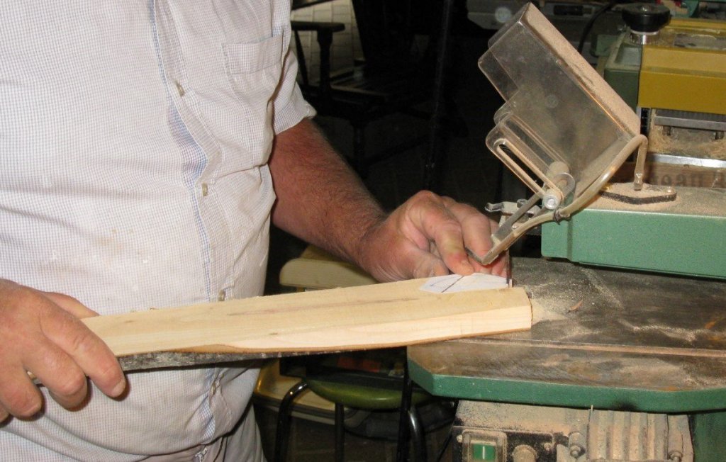
3.6 The apron is shaped accordingly the waterlines.

-
3.5 The stem is fit with at tap for a strong fastening with the keel. Although the picture is hazy, you can see the rabbet for the hull planks. On the next picture the stem is provisionally set on the keel.

-
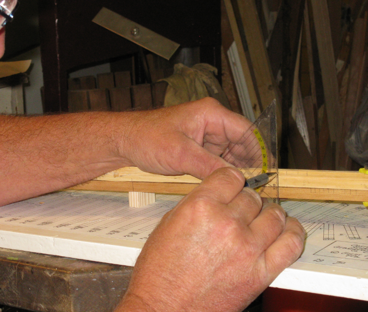
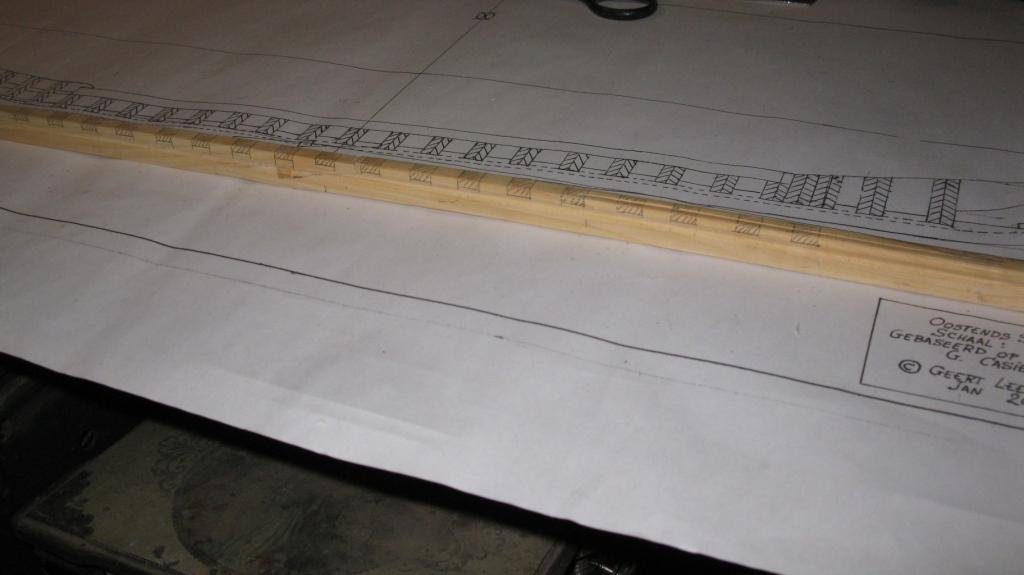
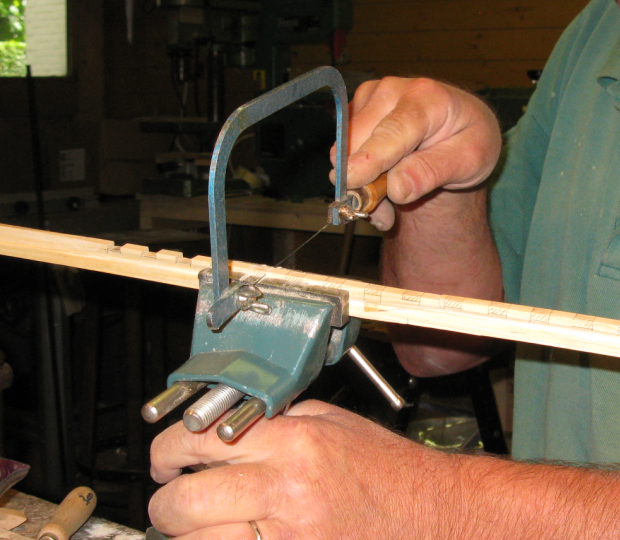
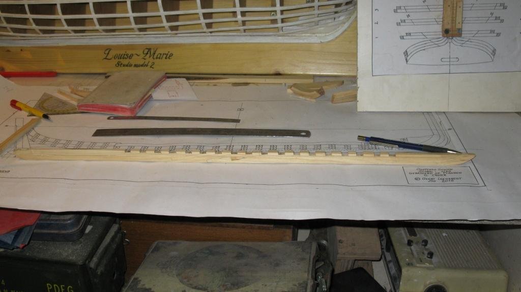
3.4 The 18 square frames will be sunk in the keel in floor seatings. I mark the placement of all square frames on the keel assembly an saw them out.
-
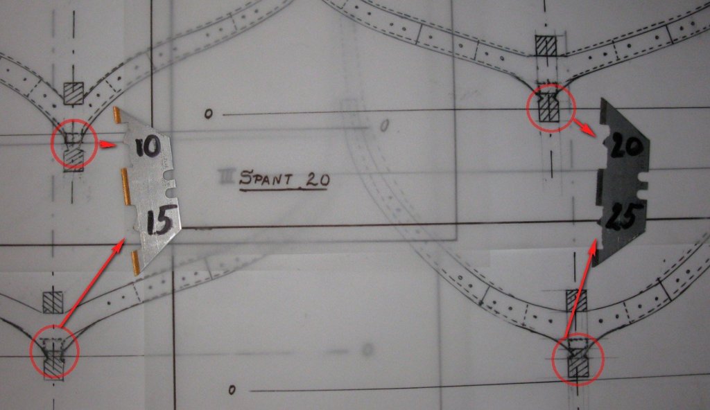
3.3 Now the rabbet for the lowest hull plank has to be cut. The angle of that plank varies along the different stations. I make a scraper for every 5 stations between the stations 9 and 26 and scrape the rabbet along the keel changing the scraper every 5 stations.
-
3.2 I made the keel, the stem and the stern simultaneously but I will deal with one after the other in this report for clearness' sake. The keel is made in two parts with a keyed hook scarf in the middle. I saw the scarf with the fretsaw. The scarf is keyed with two wedges. The two parts of the keel are glued together. Once dry, I saw the wedges along the keel and sand them.