G.L.
-
Posts
1,553 -
Joined
-
Last visited
Content Type
Profiles
Forums
Gallery
Events
Everything posted by G.L.
-
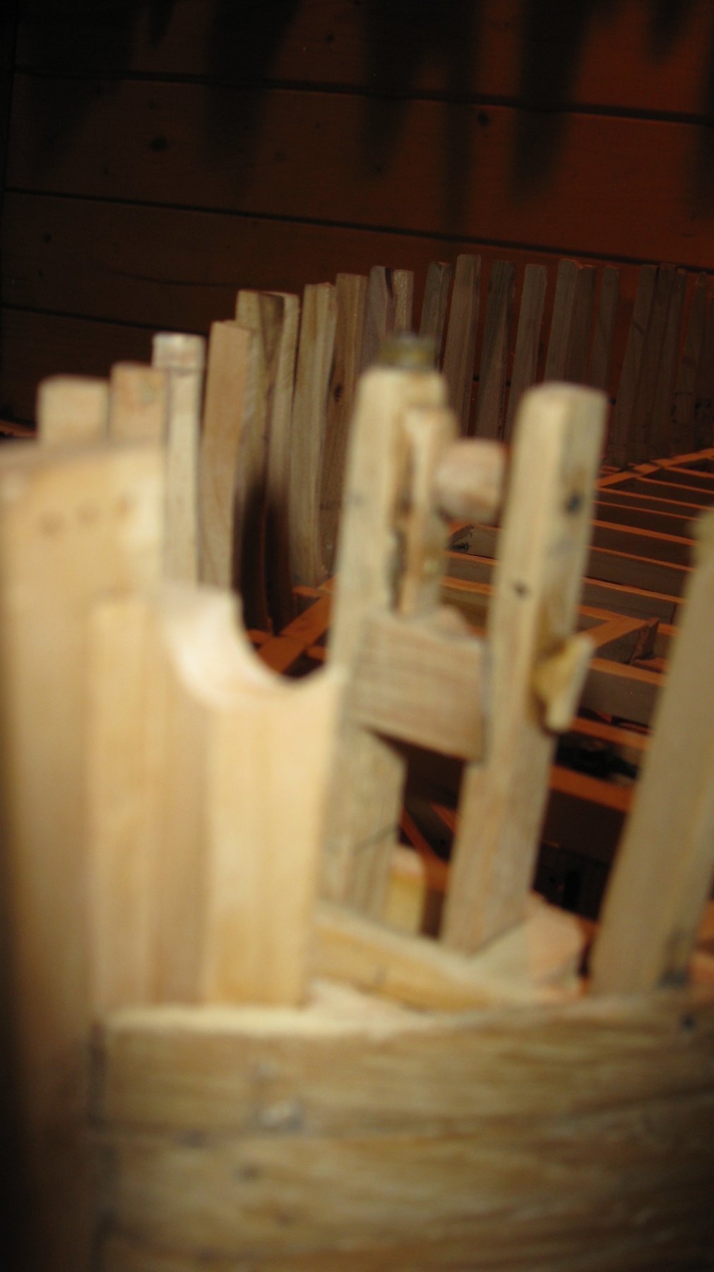
 The jib boom support finally into position. Remark the round groove in the port knight head for the bow sprit, it was filed out with a round file.
-
10.5 A wooden roll which will guide the jib boom when it is rolled in or out is added.
-
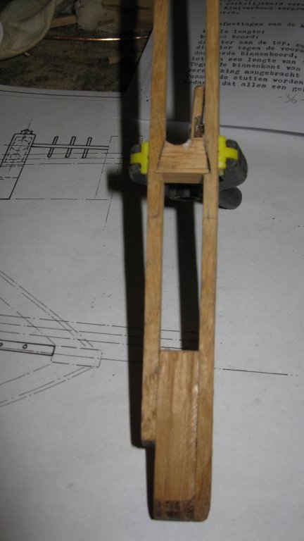
10.4 The stringers are shortened to the correct height and the clamp is glued into position. A sheave is added on top of the starboard stringer.
-
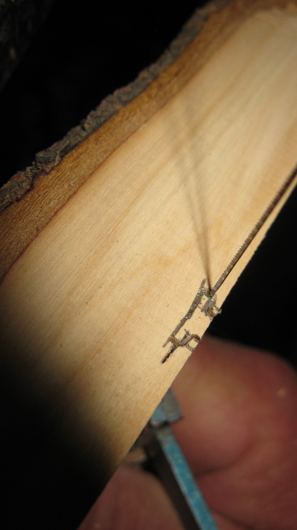
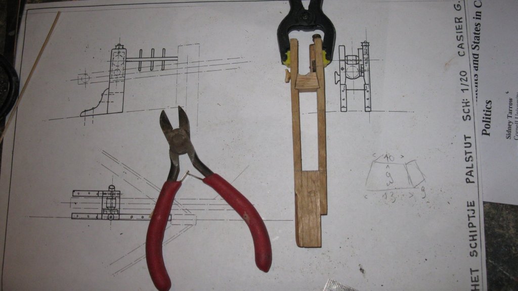
10.3 Sawing the clamp for the outside of the port stringer.

-
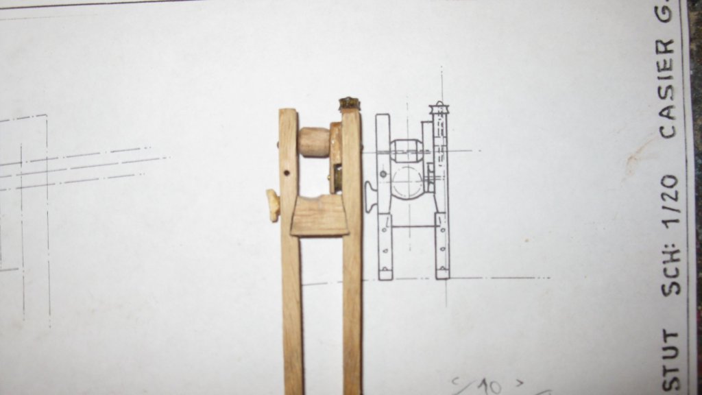
10.2 The block is glued between the stringers in the slots and on the inside of the starboard stringer a sheave shell is glued into position.
-
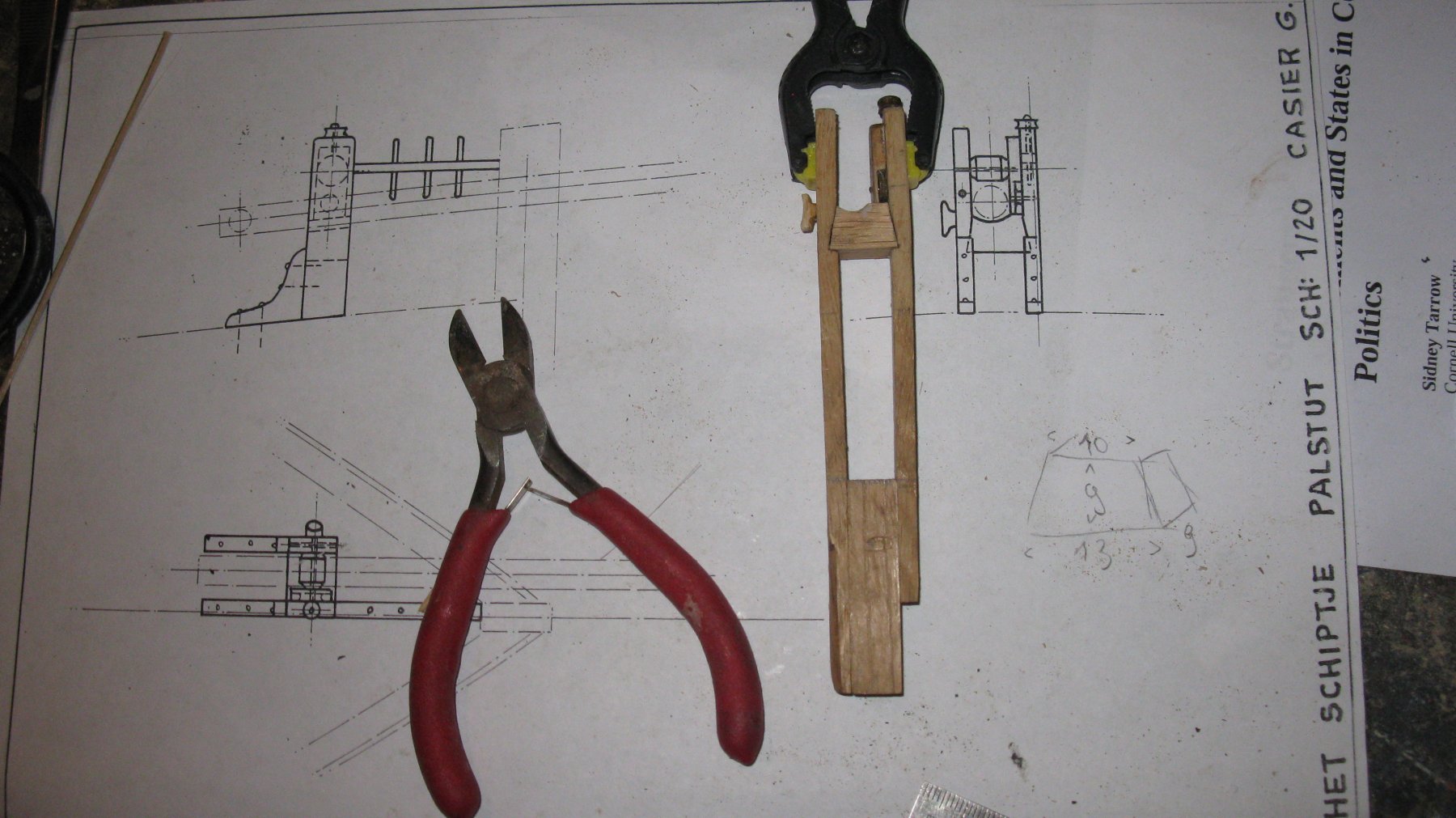
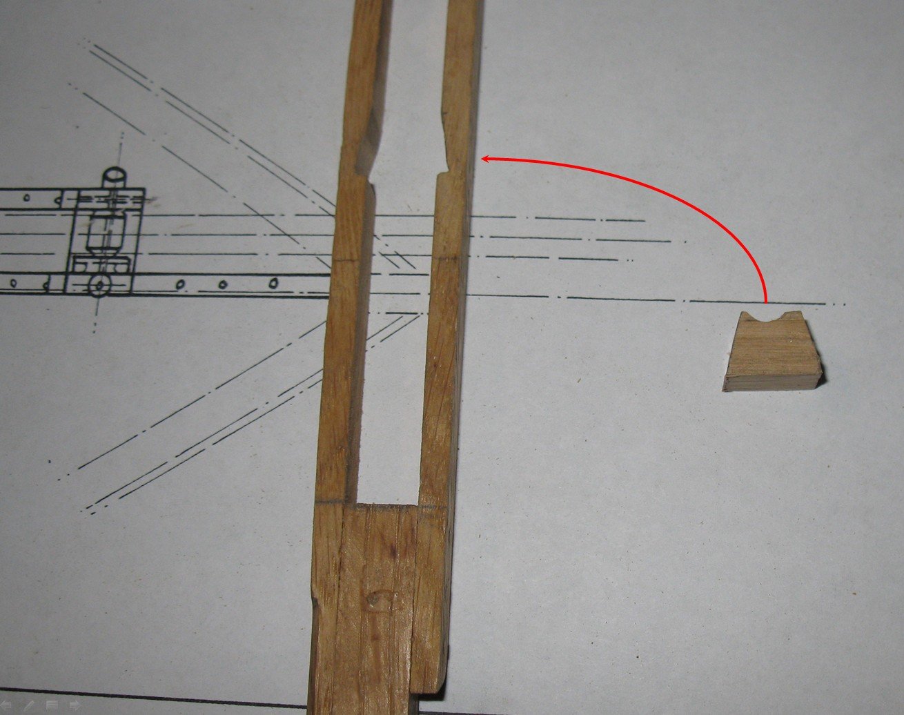
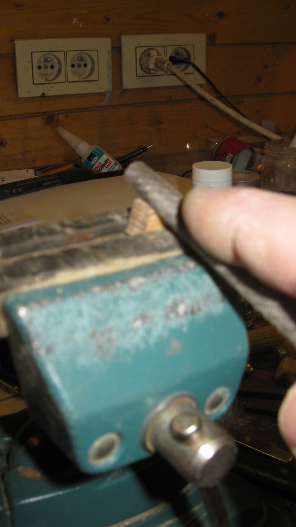
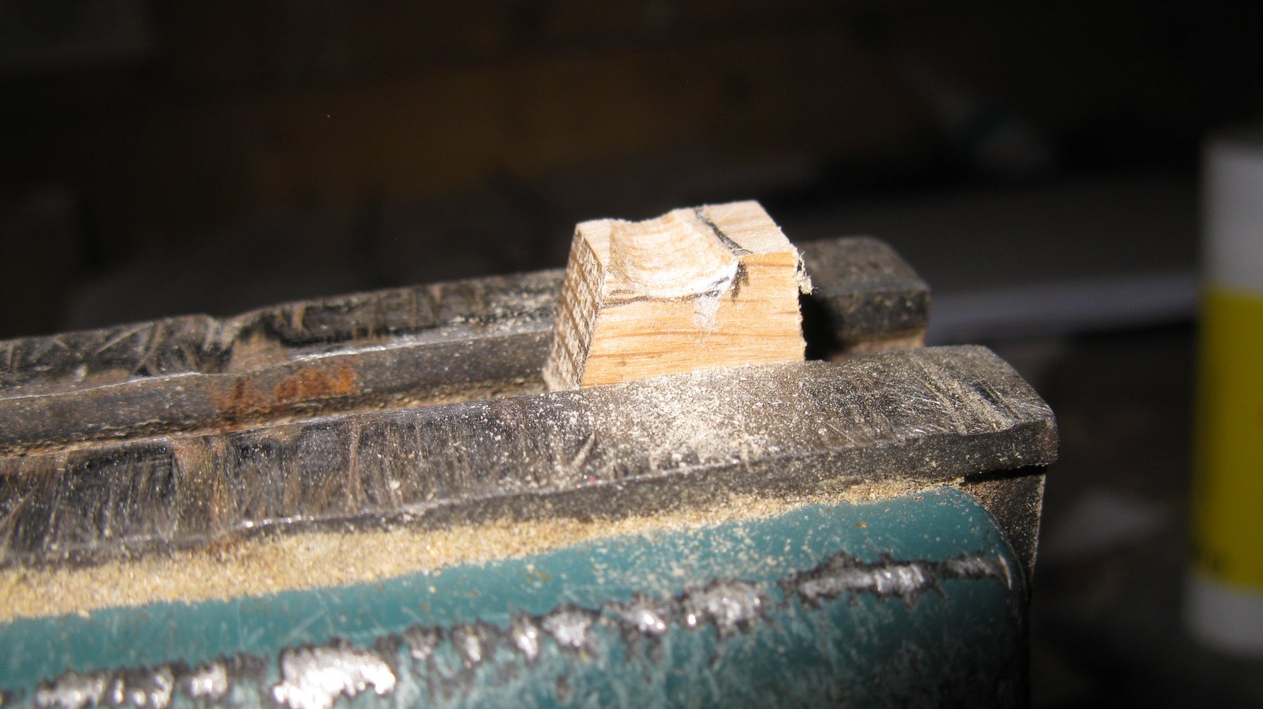
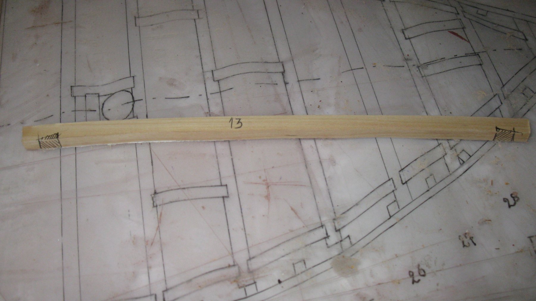
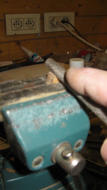
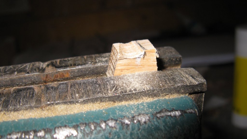
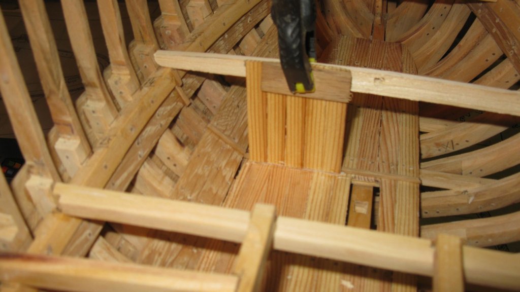
10: Finishing the jib boom support 10.1 In part 7, post 7.1 I made the stringers of the jib boom support. Now it is time to finish it. Once the deck is laid it can't been removed any more. I start with cutting the slots for the block on which the bowsprit will rest. The block is sawn from a small piece of oak and the round groove for the bowsprit was filed in it with a round file.

-
9.15 Some of the deck beams have to be sawn trough for the gaps of the hatches.


-
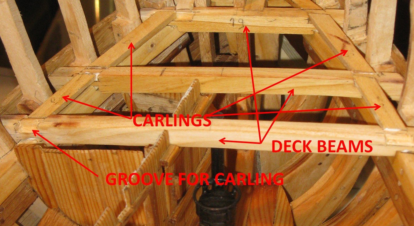
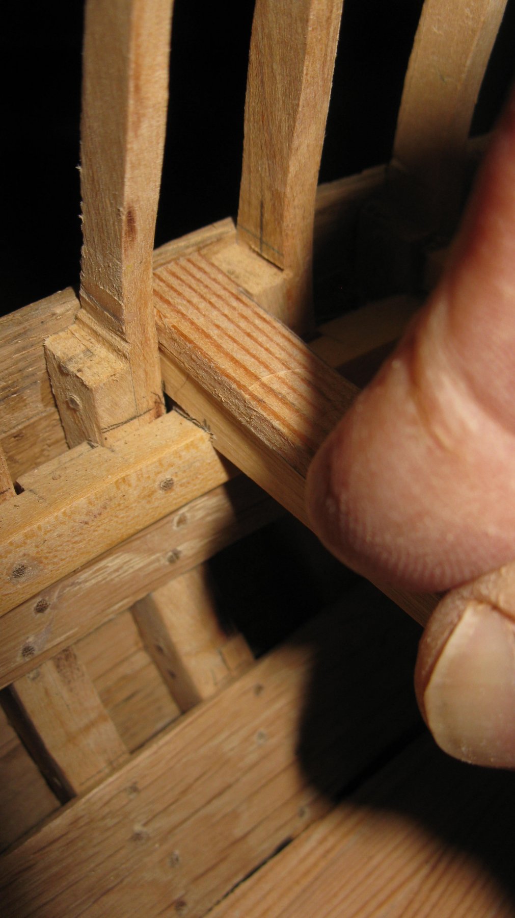
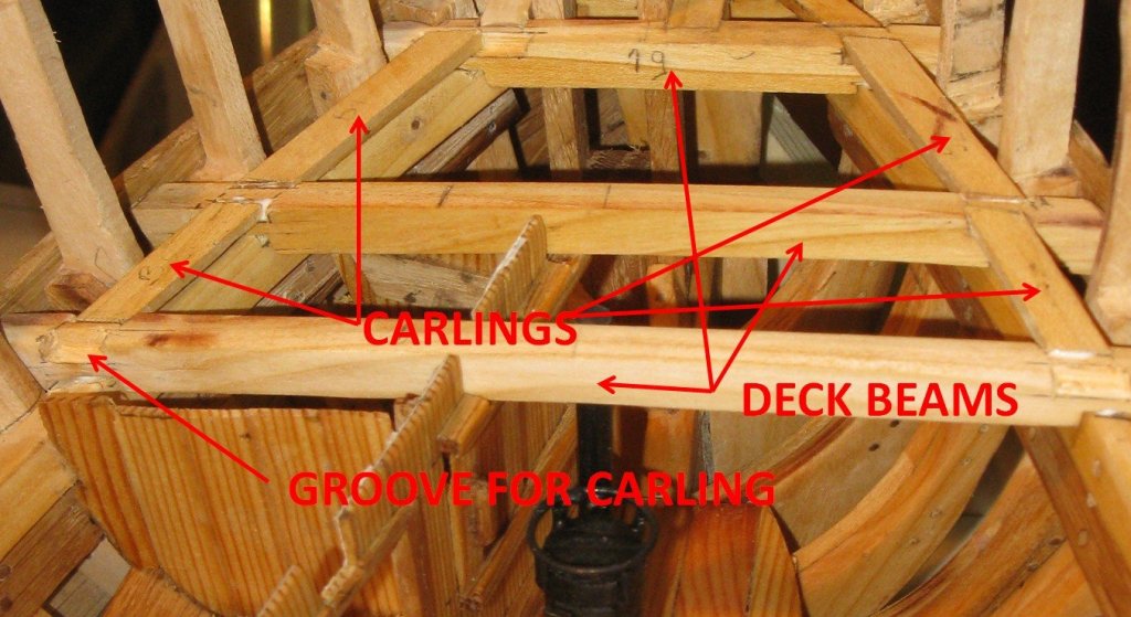
9.14 While placing the deck beams, I make the grooves for the carlings which will connect the beams on the edge of the waterway.
-
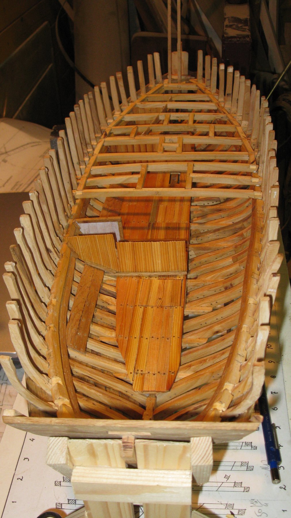
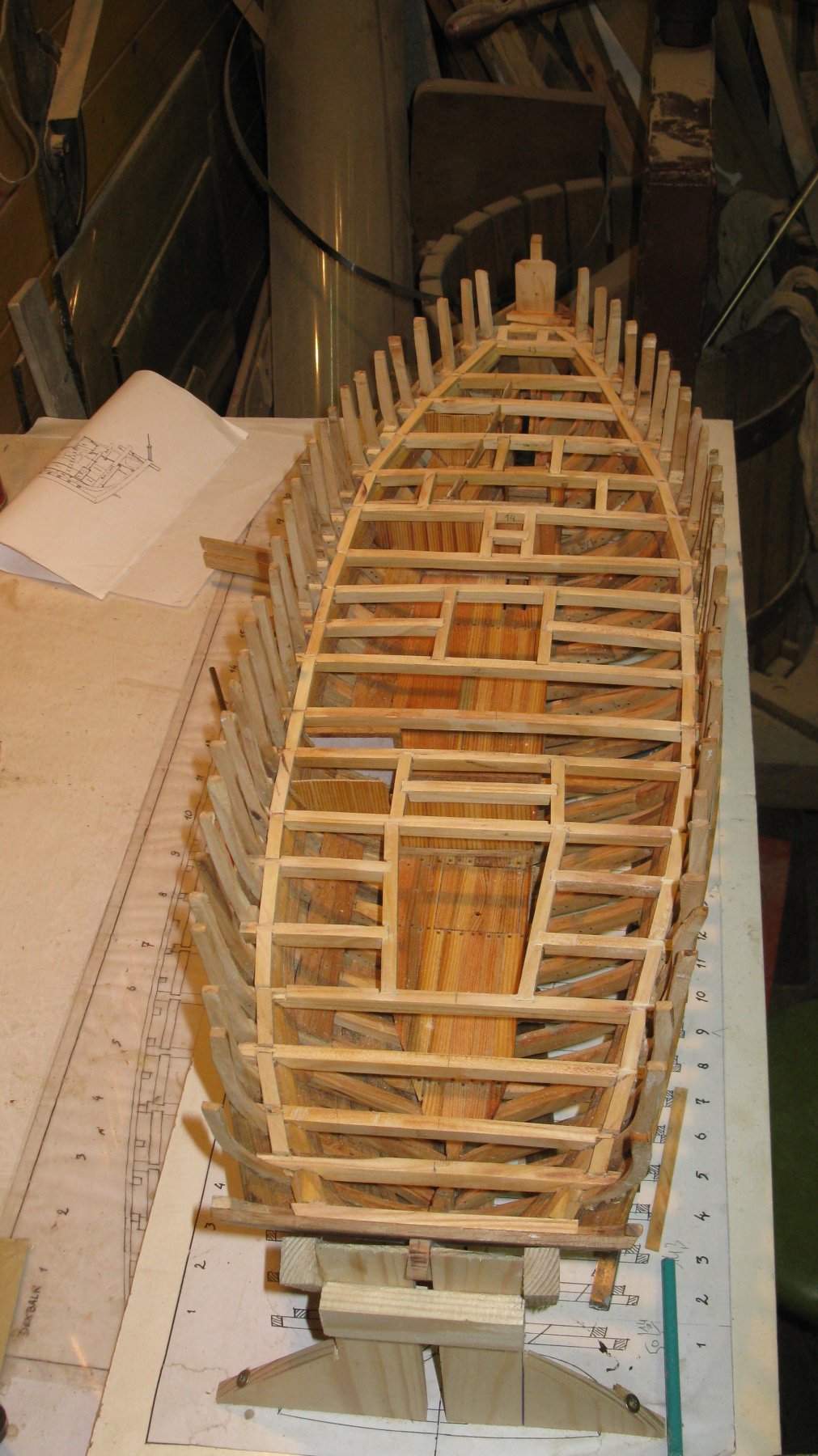
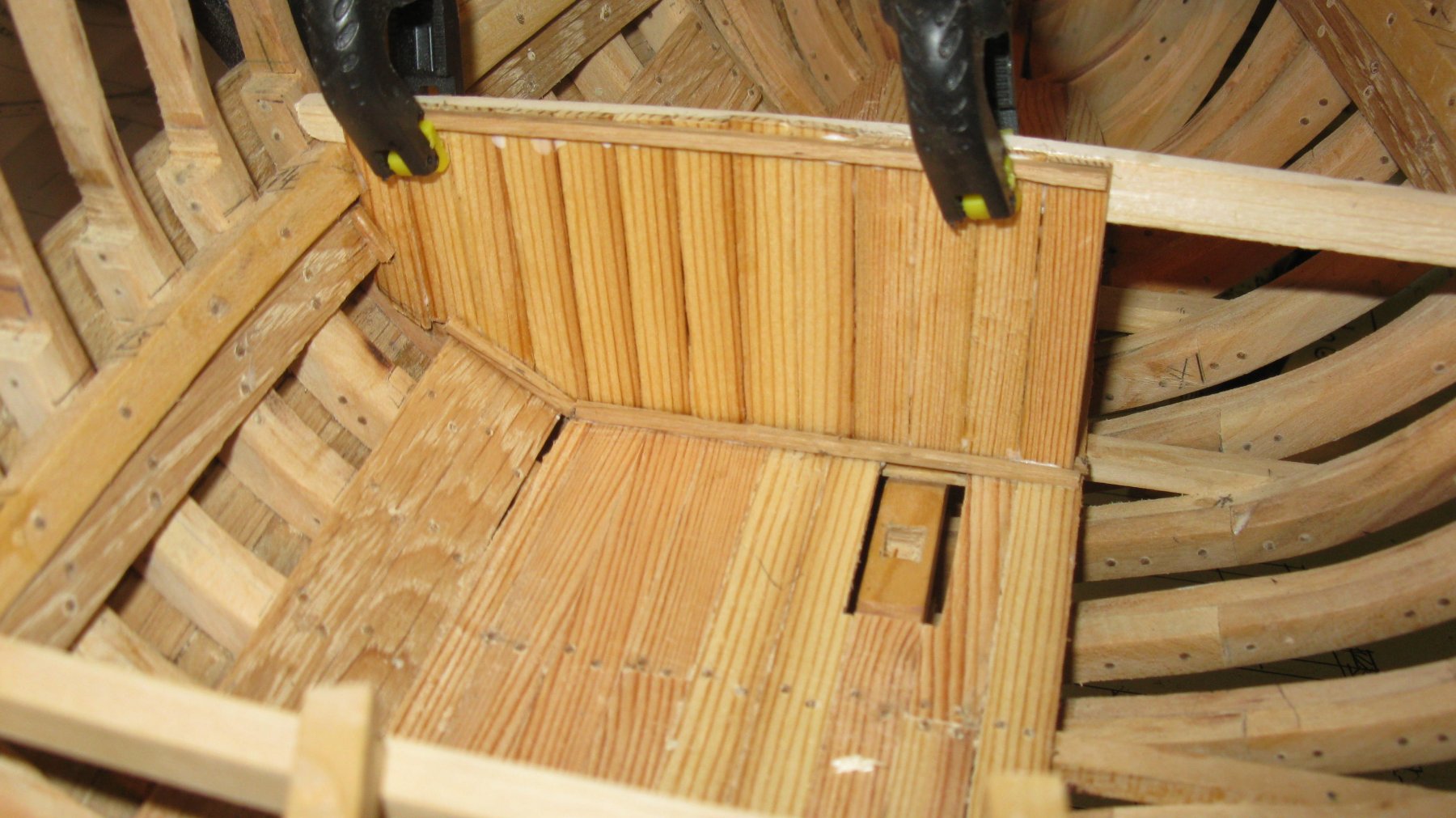
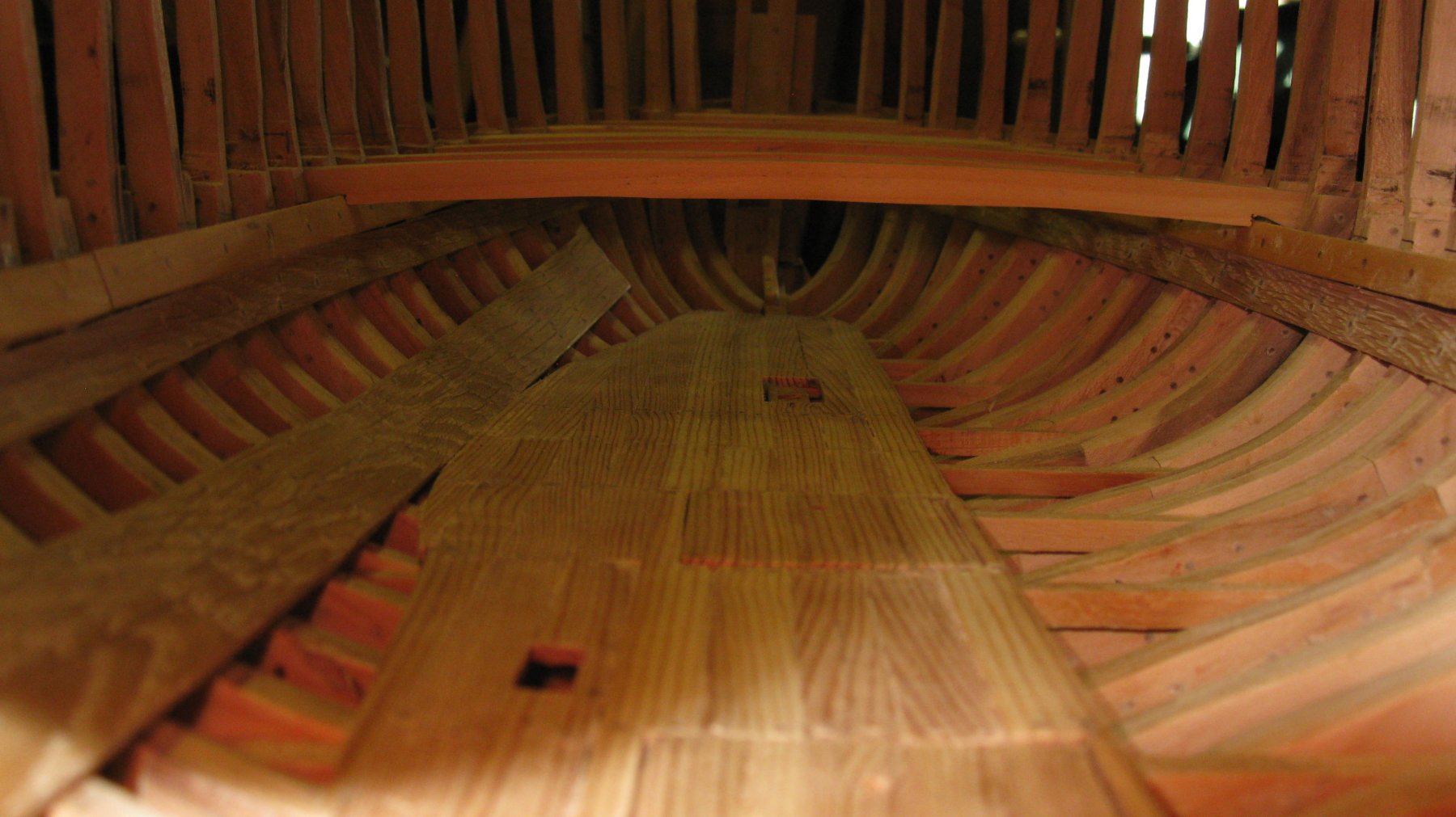
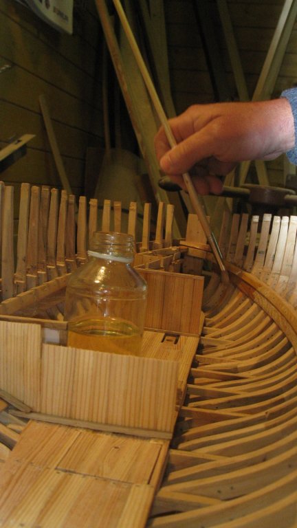
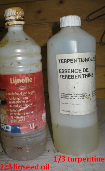
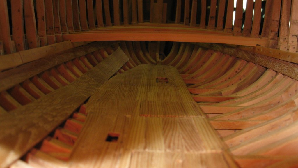
9.13 Now the bulkheads are in place, the deck beams can be glued into position. Before doing that, I coat the inside of hull with a blend of 2/3 linseed oil and 1/3 turpentine. With the deck beams in place the inside of the hull won't be accessible any more
-
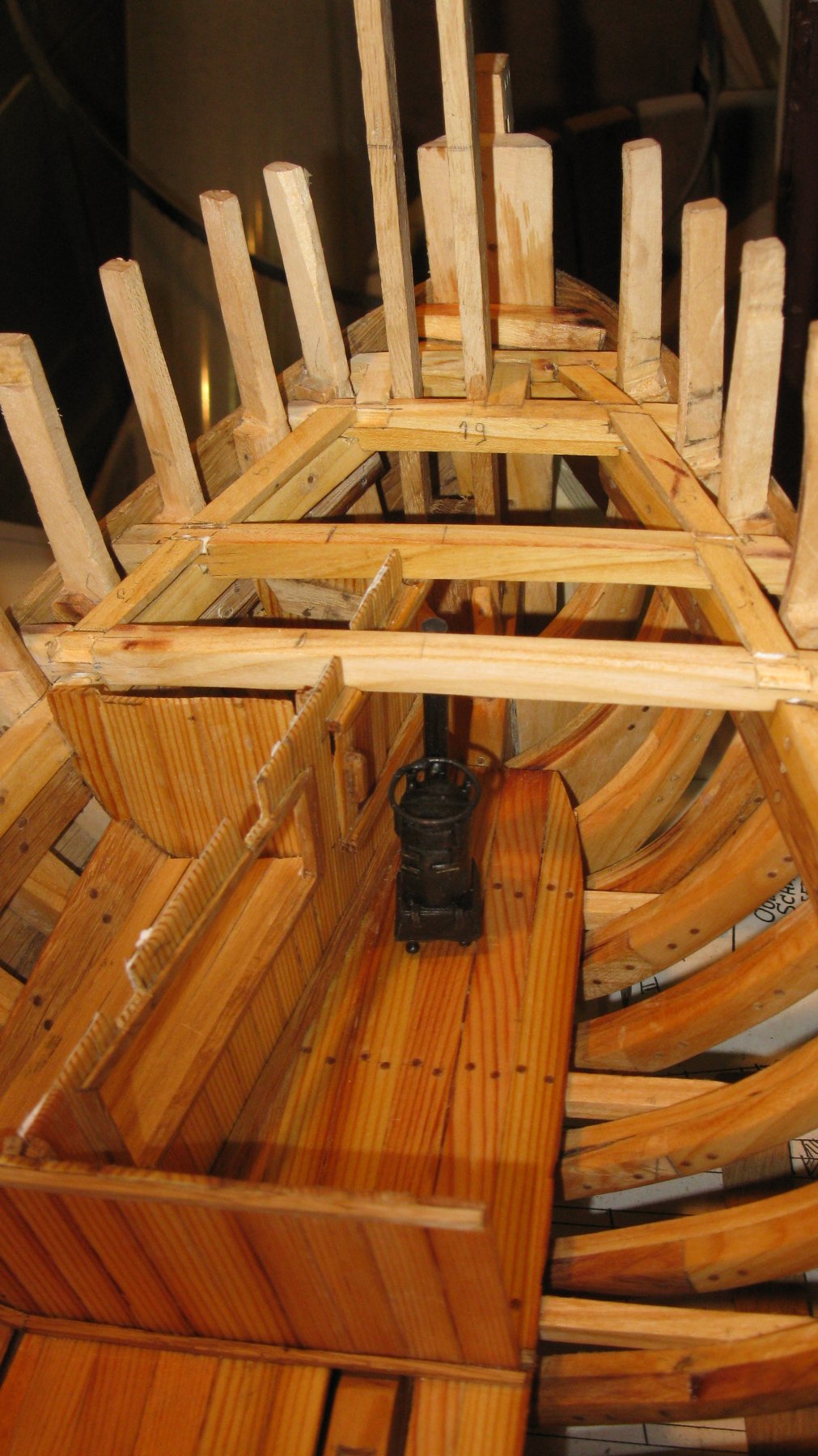
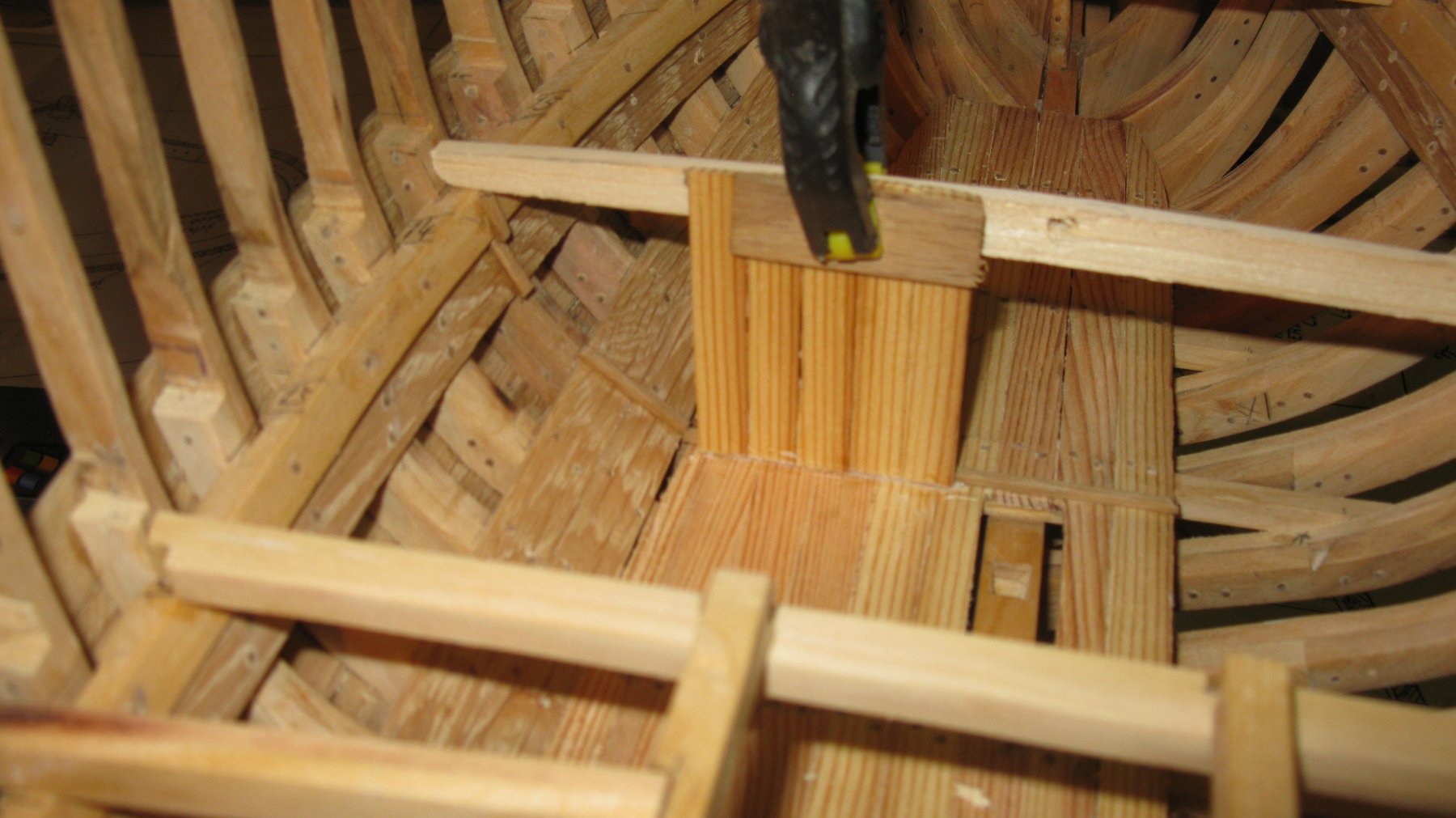
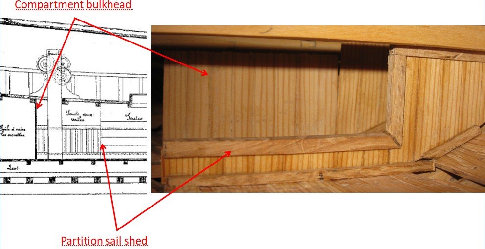
9.12 The fish hold is separated from the sail shed by a low partition. In the sail shed the stringers for the fishing winch are not yet in place.
-
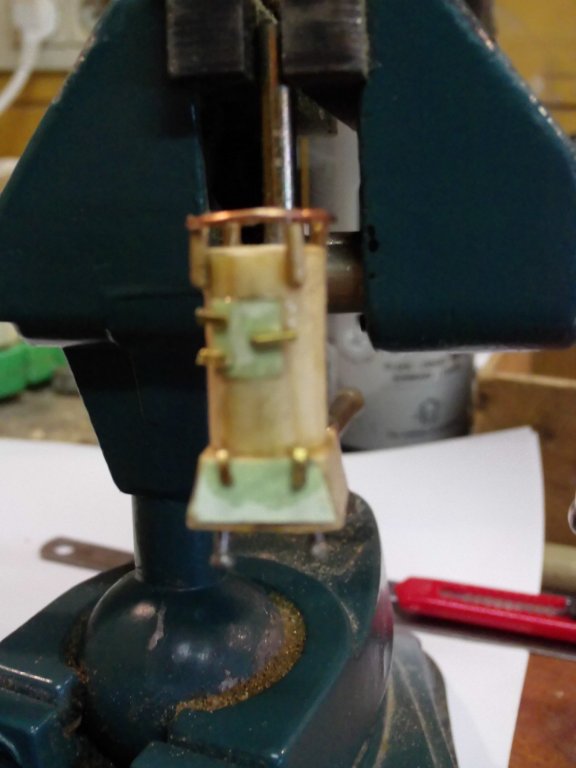
9.11 The stove, after it has been painted black and placed in position in the crew shelter.

-
9.10 The lids are of cardboard, the hinges of small pieces of brass and the ring at the top side of a piece of copper wire
-
9.9 The 90 degrees bent stove pipe is made of a nail/bolt.

-
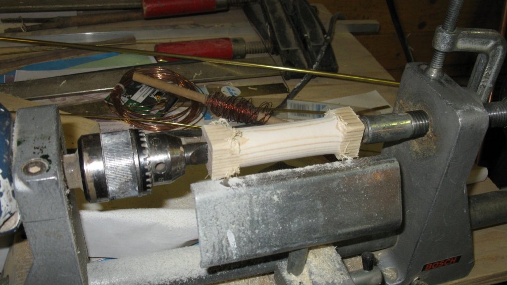
9.8 As metalwork is not really my thing, I make the stove with a mixture of materials. I make the body of wood with the help of the lathe (drill converted into lathe).
-
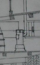
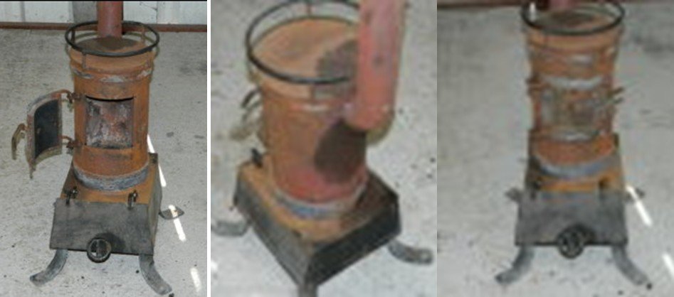
9.7 To design the ship stove I used some photos from the internet.
-
9.6 The crew shelter is accessible via stairs. Sawing of the stringers. I see that I didn't make any more photos of the making process. Therefore I a add a picture of the end result. A bit difficult from between the frames.

-
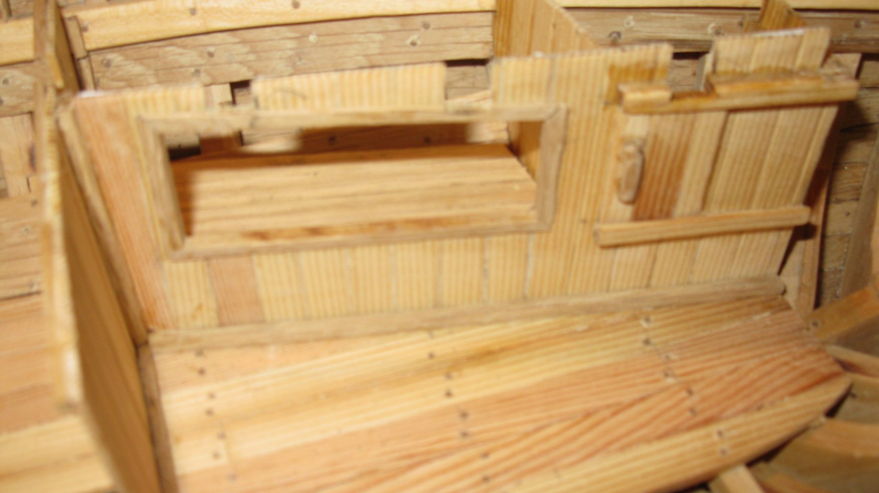
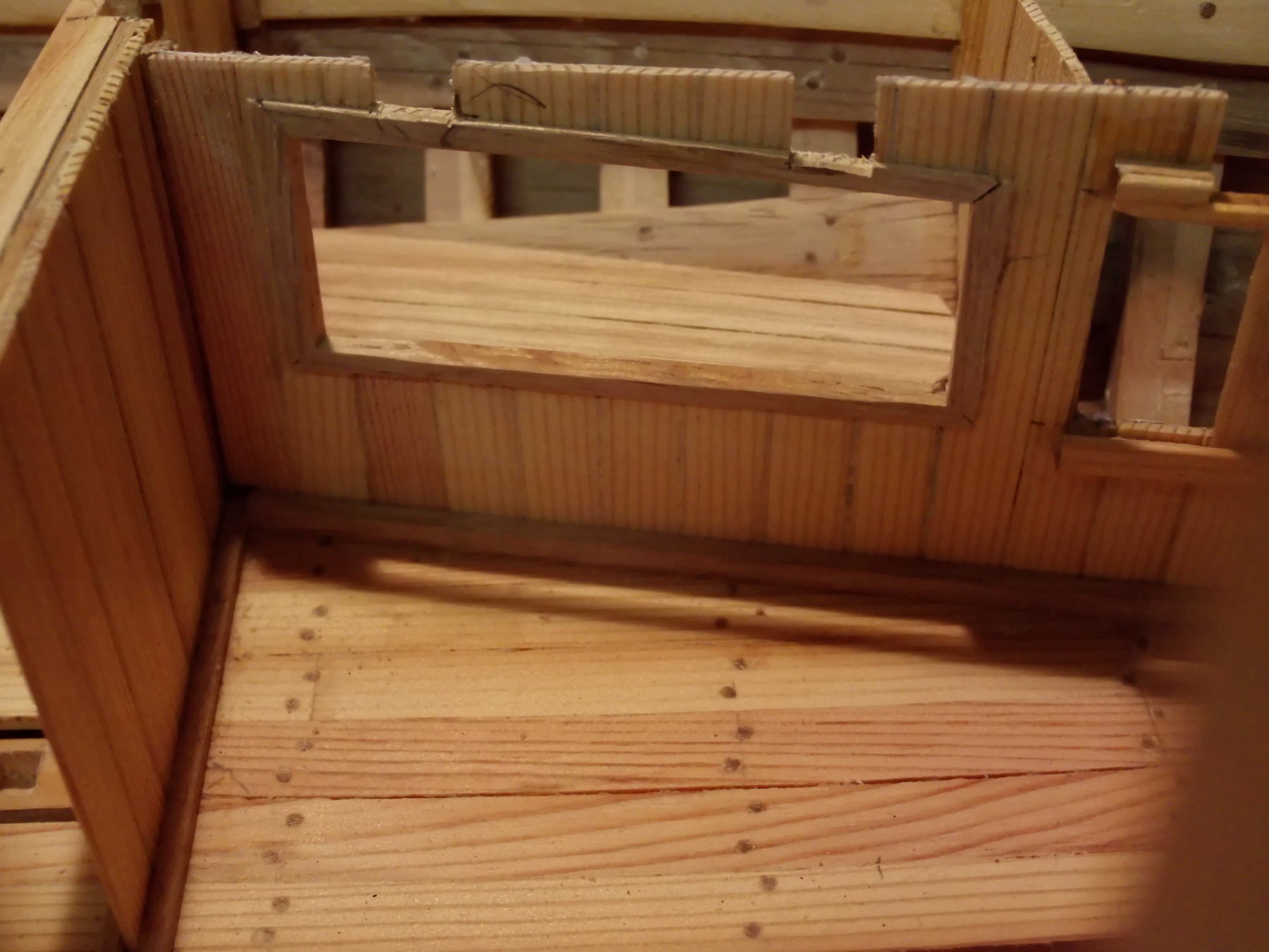
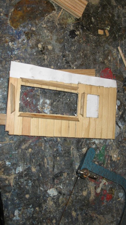
9.5 The assembly of bunk and provisions locker.

-
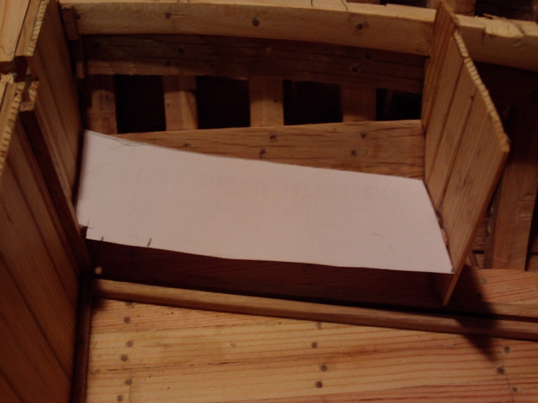
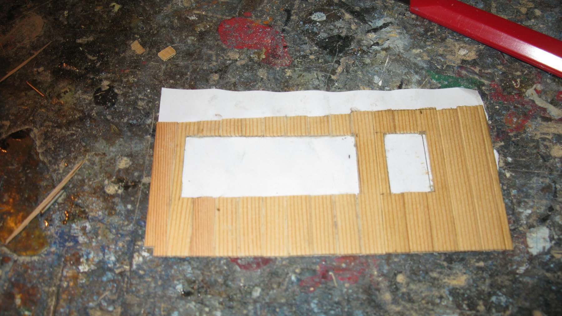
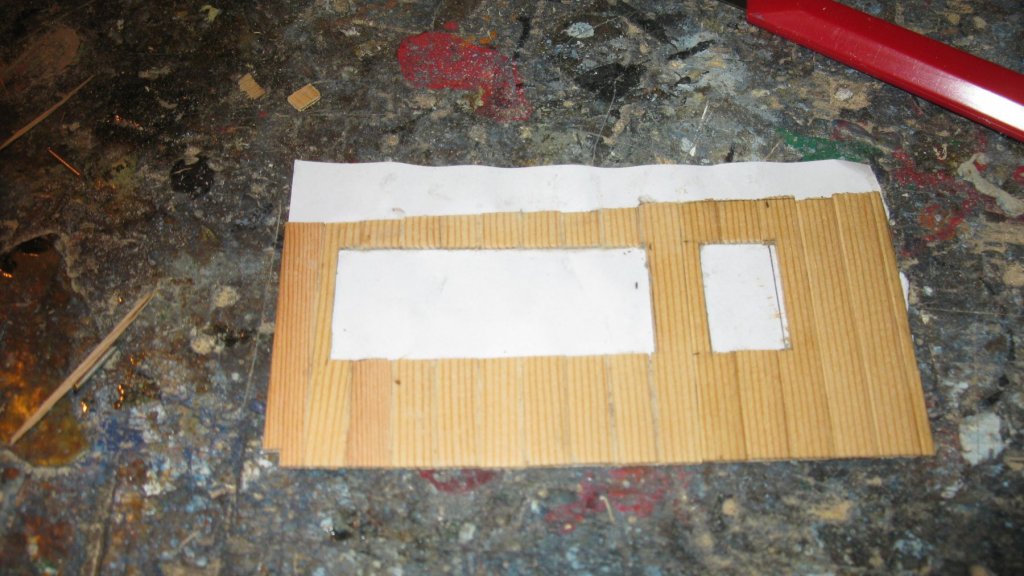
9.4 I make a paper template to determine de shape of the bunk bottom planks.


-
9.3 In the crew shelter were some bunks and a stove (see part 8 post 8.4). When I measure the space in the model, it is all very tiny, much more than the sketch in part 8/post 8.4 suggests. The headroom is only 120 cm. So there is no space for two bunks in line. I decide to make one bunk and a provisions locker.


-
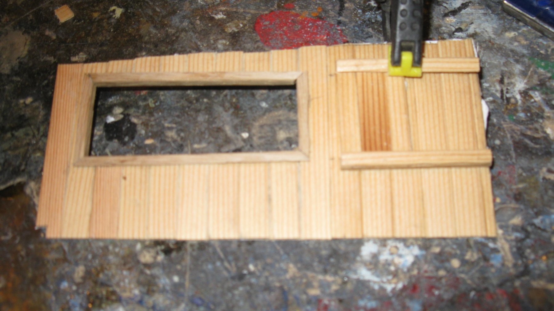
9.2 When all the planks are raised, I glue the support slats to the other side.

-
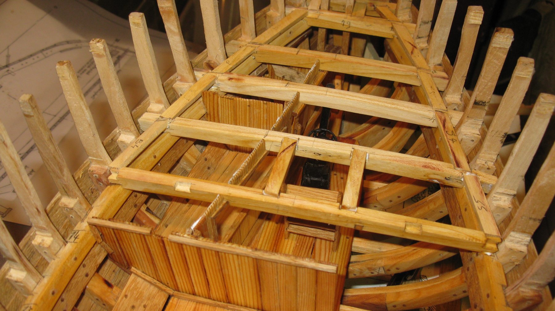
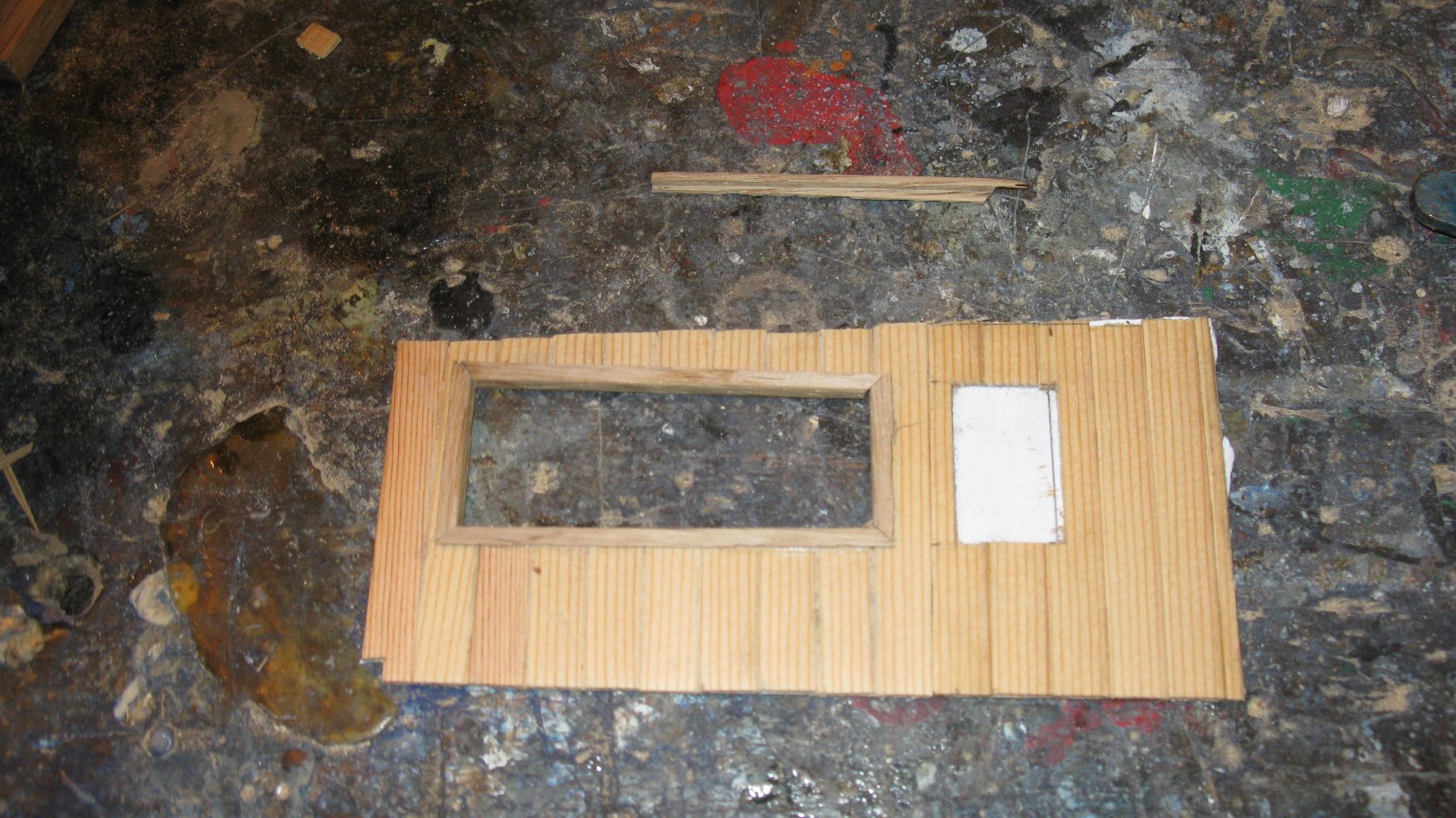
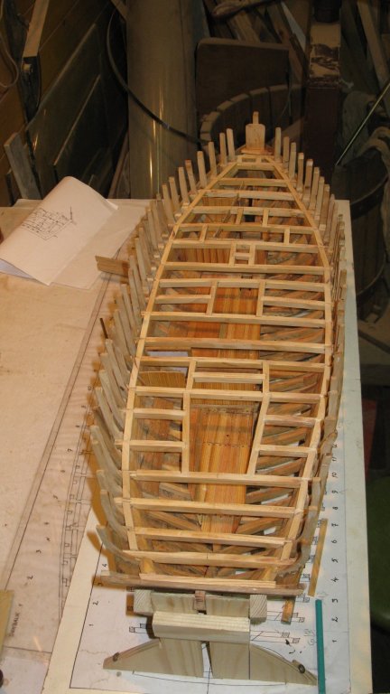
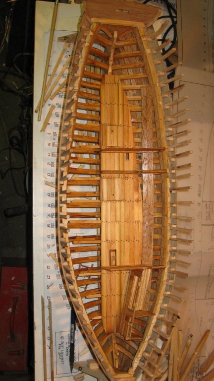
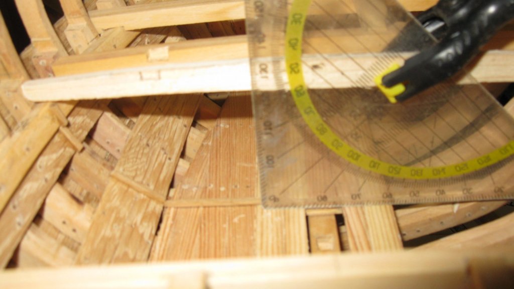
Part 9: Compartments below deck 9.1 Making the compartments: The hull is divided in three main compartments. A crew shelter in the front, in the middle a fish hold and sail/rope/net shed and aft a shrimp cooking store. The bulkheads between the compartments are made from pine planks and do not allways rest against a beam at the top. On the deck and the side face I glue small support slats. A wooden template with the deck beam curve on top indicates the height of the bulk head planks and props them while I glue them. The first plank is erected with the help of a triangle.
-
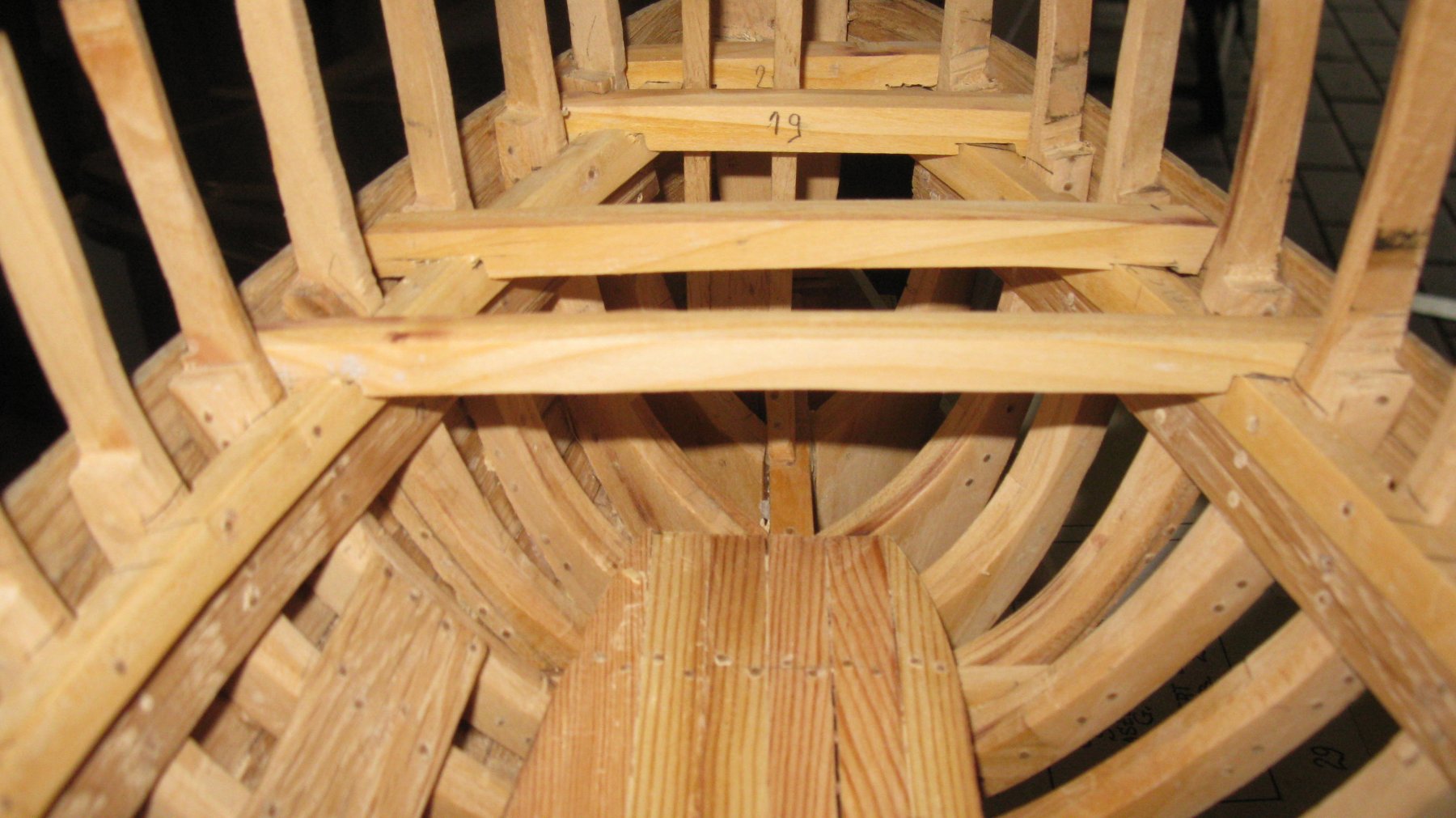
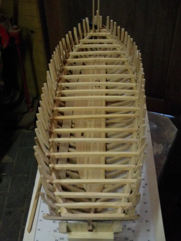
8.21 All the deck beams are made and laid in position. They are not glued yet because I want to divide the hull into compartments first and some of the beams must be shortened to make place for the hatch openings.
-
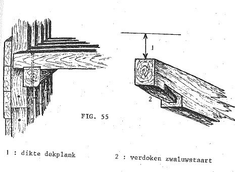
8.20 On the real ship the beams were fitted with hidden dove tales, but making those is beyond my skills. I will ignore them, they are hidden anyway so it will not be conspicuous.


-
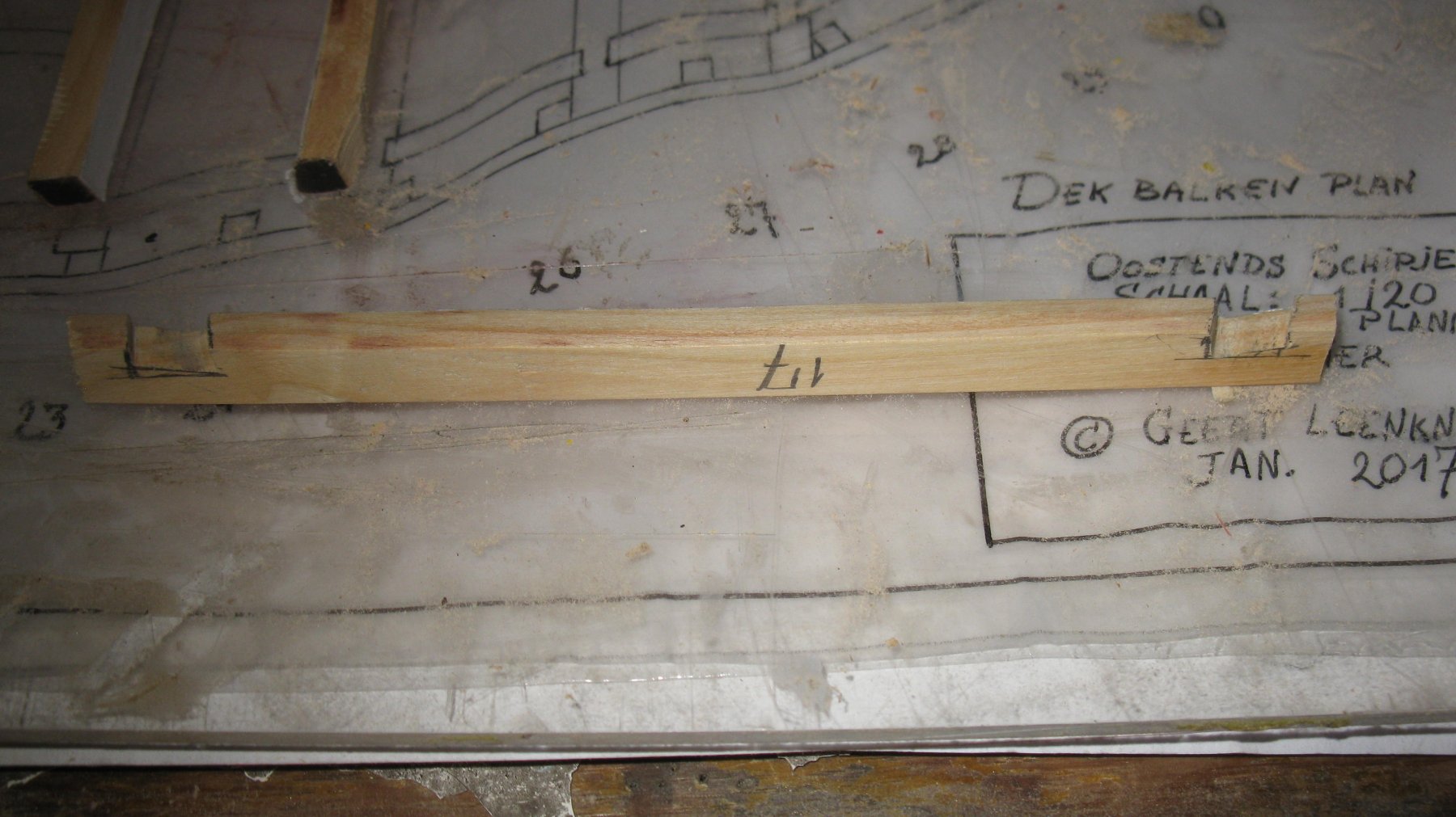
8.19 Once the deck beams will be fitted in the model, it is important that their upper side is at the correct height. In this case that means one deck plank width below the top of the wale. I check the height with a small plank of 3 mm thickness (thickness of the deck) and mark the size of the notches to be sawn in the deck beams.

-
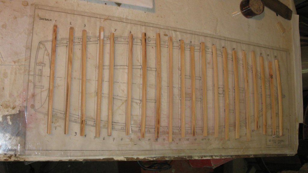
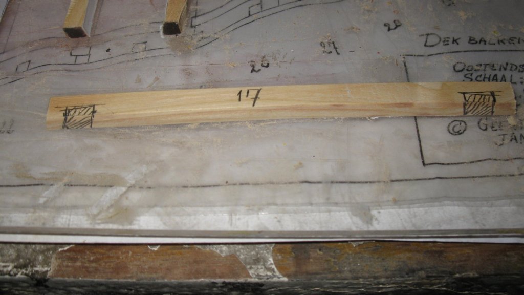
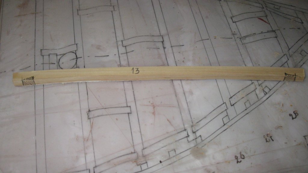
8.18 All the deck beams, lined up on the plan.