HOLIDAY DONATION DRIVE - SUPPORT MSW - DO YOUR PART TO KEEP THIS GREAT FORUM GOING! (Only 36 donations so far out of 49,000 members - C'mon guys!)
×

Kenchington
-
Posts
679 -
Joined
-
Last visited
Content Type
Profiles
Forums
Gallery
Events
Everything posted by Kenchington
-
 So true! Especially if you can pay someone else for the annual maintenance. I owned a wood lapstrake boat back in student days. Lovely. But spring preparations usually extended through to almost September. Diomedea is mostly GRP, aside from teak trim and fittings, jatoba gratings, plus the sailing and rowing gear (pine, Douglas fir, ash, some oak here and there). Less maintenance and more sailing time 😀
- 86 replies
-
- 2
-

-
- Model Shipways
- Norwegian Sailing Pram
- (and 3 more)
-
Does any kindly soul on MSW have access to Hendrick Busmann's 2002 book "Sovereign of the Seas, Die Skulpturen des britishen Königsshiffes von 1637" (Hamburg, Deutsches Schiffahrtsmuseum Bremerhaven und Covent Verlag), along with the ability to read the German text and a little time to fill me in on Busman's conclusions? Used copies of the book go for $200 and up, which is more than I am willing to pay for a book that I couldn't read! A bit of background: A couple of years back, I got interested in unravelling the many misunderstandings that have grown up around Sovereign of the Seas (the 1638 ship of that name). I have slowly been pulling information together into a sort of extended essay and I thought that the last published study I would need was Janice Valls-Russell's 2021 chapter on Heywood's contributions to the ship. I have finally got hold of that through interlibrary loan, only to find that she confined her study to Heywood's booklet (originally intended as a commemorative piece for the launching pageant that never happened). For the carvings on the ship, Valls-Russell refers readers to Busmann's work. I have access to all of the original evidence and I don't need yet another re-telling of the ship's story (and certainly not if it is as erroneous as most that have come before!). I have even managed to identify a lot of the imagery in the carvings: Zodiacal signs, trophies of arms, symbols of Charles' four kingdoms, the special feature of Charles as King Edgar (the supposed Sovereign of the Sea), gods of wind and wave, etc. etc. Valls-Russell's work on Heywood's booklet has let me recognize the half-hidden allusions to the myth of Jason and the Argonauts, beyond the two large figures on the tafferel (e.g. the sorceress Medea in her chariot, being drawn by dragons, along with Aphrodite in hers, drawn by swans). However, I suspect that Busmann's knowledge of 17th Century sculpture will have let him detect things in the Payne engraving or the "van de Velde" drawing (which wasn't by either of the van de Veldes) that are just a blur to me. Hence my interest in what he concluded. Very, very many thanks in advance, for anyone who can help me out! Trevor
-
What we had in the UK, when I was a kid, was a lot of vessels still in some sort of use -- so maintained for use, not preserved for posterity. Unicorn was one but there were many others, some since restored and preserved. I got to see Warrior while she was still an oil wharf in Pembroke Dock, then long after went all over her in restored condition in Portsmouth, for example. Great Britain came home later in my time. I didn't get to see her come up the Avon but I did visit her soon after her arrival, then many times after my parents moved to Bristol.
-
In my early years, it was the other way around. You had many preserved ships of many kinds, right up to battleships and Queen Mary. We had Victory, Cutty Sark and not much else. Peking could have stayed but went to New York instead. Now she has gone to a more appropriate home in Germany as the South Street collection withers. I suspect that it is a case of an initial surge of enthusiasm, then the bills pile up, volunteers dry up, maintenance falls off, the public gets complacent -- and before you know it, its time to start over with a whole new round of preservation. Trevor
-
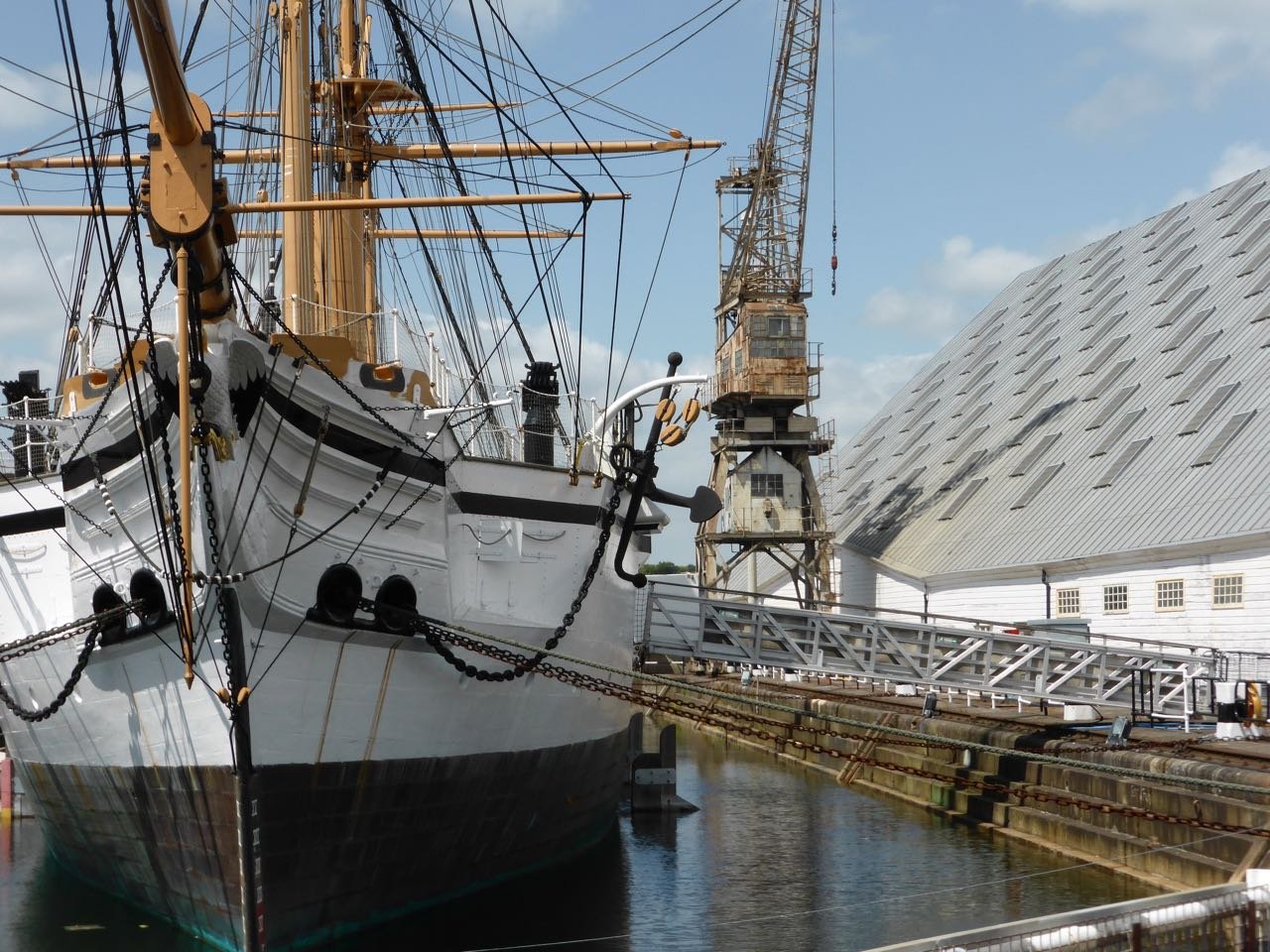
When navel hoods can be naval ... I was trying to tie down the origins of the painted ceiling in the Commissioner's House of Chatham Dockyard (don't ask!!) when I blundered into this image: That's HMS Gannet of 1878, now restored. The shipwrights who built her may have called the structure extending from hawse holes to figurehead the "cheeks of the head" or some such. Still, looking at that, it's not hard to see why McLean chose "navel hood" for McKay's reinforcing structure, if his early versions enwrapped the hawse holes of his clippers. Not identical structures, of course. Nor the same kind of ship, nor quite the same time period. But when a term was needed for something new and rather different ... Trevor
-
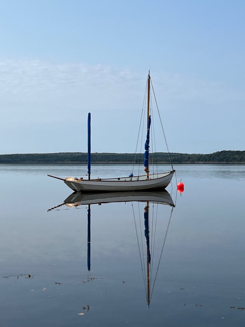
Mine's a Drascombe Longboat: That image is from last summer. Just got her back on her mooring this afternoon, with lots of work still to do to clean her up for the season, then get the sailing gear on board before she looks like that again! Trevor
- 86 replies
-
- 7
-
-

-
- Model Shipways
- Norwegian Sailing Pram
- (and 3 more)
-
Not even that far. I'm trying not to think about it until I have the tiller itself done. And that has to wait while I get my (full-size) boat into the water and onto her mooring! But thanks for your explanation: Gives me something to try. Trevor
- 86 replies
-
- 3
-
-
- Model Shipways
- Norwegian Sailing Pram
- (and 3 more)
-
I'm still working on my version of the pram's tiller. Good to see that you managed to make the kit-supplied one work! Too many others haven't. How did you get the brass through the tiller extension? I have no clue how that could be done! Trevor
- 86 replies
-
- 1
-
-
- Model Shipways
- Norwegian Sailing Pram
- (and 3 more)
-
Don't beat yourself up over it. If your fingers hadn't slipped, the spellchecker would have swapped the vowels on your behalf 🙂 One of the key documents on earlier English shipwrightry dates from the 1620s (though the surviving manuscripts are copies from a half-century later). It mentions "naval timbers" or maybe "navel timbers" as something like what McKay would have known as a futtock. As there was no concept of a "correct" way to spell English words at the time, nor for a century later, "naval" and "navel" were interchangeable, though quite different in their origins and allusions. So what were the timbers? Something associated with navies? Something in the centre of something else? I once wondered whether they might have been a development introduced by Basque shipwrights, who had formerly been subjects of the Kings of Navarre. There is no way to tell. We are simply left trying to understand the nautical technology of times past, while peering through a fog of confusion and presented with very scattered evidence. Research is a process, not an end-point. If we keep pushing forward, someone will get there in the end. Trevor
-
What a clever way to make a basket!
-
There was a tie when the Smithsonian sold larger copies of Chapelle's many ship and boat plans. I don't know whether they still do but worth checking out. For more background (though a rather later period than the centreboard sloops), courtesy of your federal government as it was in 1890: https://books.google.ca/books?hl=en&lr=&id=v98aAAAAYAAJ&oi=fnd&pg=PA235&dq=Maine+lobster+fishery+history+sloop+trap&ots=KQi-n948T4&sig=OFip4-NeAMJY7d3w689r3XwcPxo&redir_esc=y#v=onepage&q&f=false That link will take you to the Google Books version. You can likely find others on-line.
-
Chapelle's "American Small Sailing Craft", figure 99 -- though the book-published version is very small. At least, I assume that that is what all kit manufacturers have used for their Muscongus Bay centreboard sloops. How closely the Model Shipways kit follows Chapelle's version, I will not know until I catch up to your progress! Trevor
-
Really, really nice: Well done! And you're inspiring me to finish mine. In a loose pile at the helmsman's feet. There's no chance to keep it neatly coiled, as it is hauled in and veered out with every gust of wind. Then again, in a little boat like the pram, a tangle when you need to let the sheet out will set you swimming, so one of the skills a small-boat sailor must develop is keeping that loose pile free of tangles. It comes with experience, reinforced when necessary by a dunking in cold water or (far worse) a dunking in cold water that you share with your non-sailor wife. Been there. Done that. 🥲 Trevor
- 55 replies
-
- 5
-
-

-
- Norwegian Sailing Pram
- Model Shipways
- (and 2 more)
-
Sorry about that image! It was intended for a different post that I have abandoned. In fact, I'm going to bow out of this discussion now: I'm just too pressed for time to keep up. And I'm far from sure that my interventions have been helpful anyway. Best of luck to you all as you work to resolve the various interpretations! Trevor
-
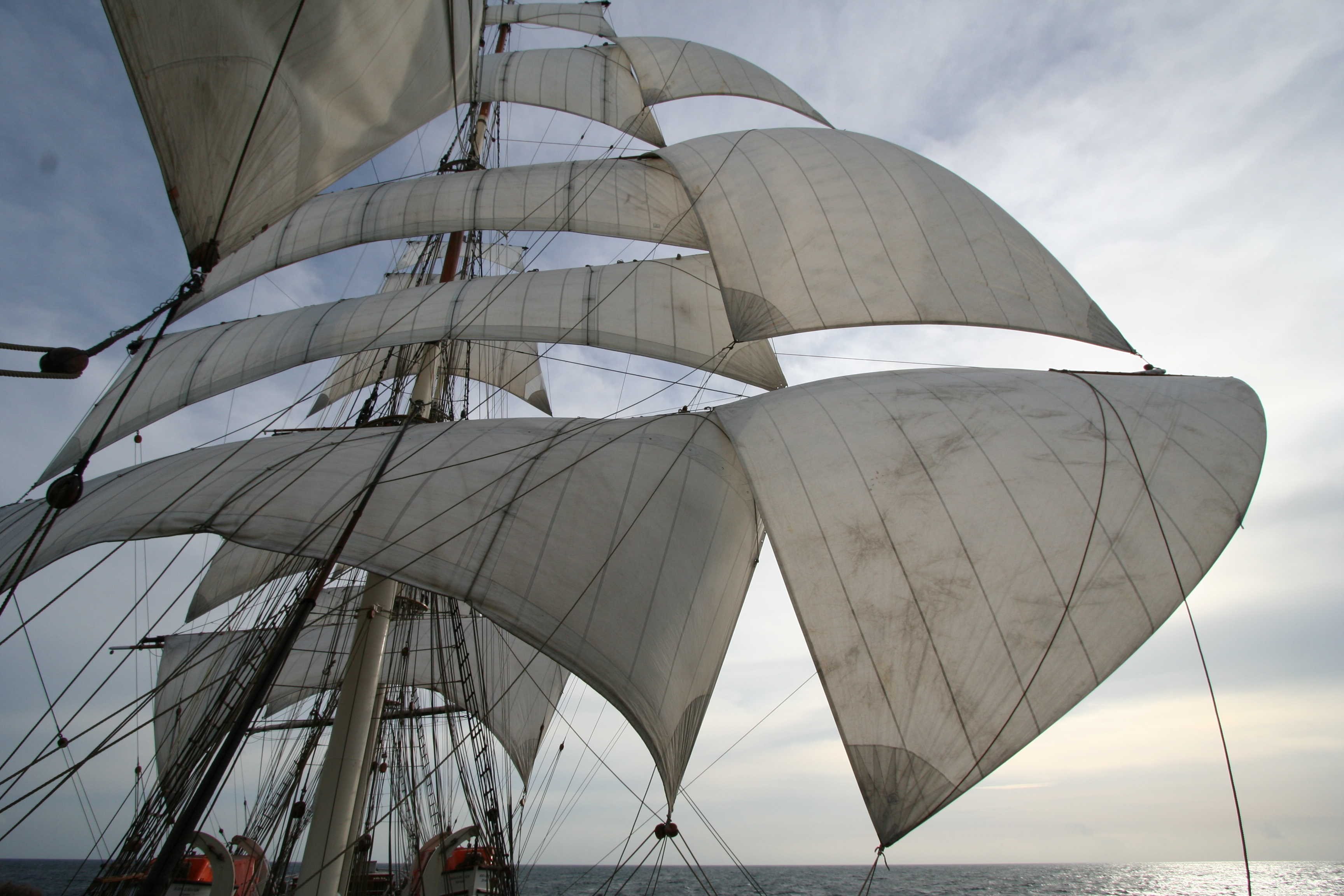
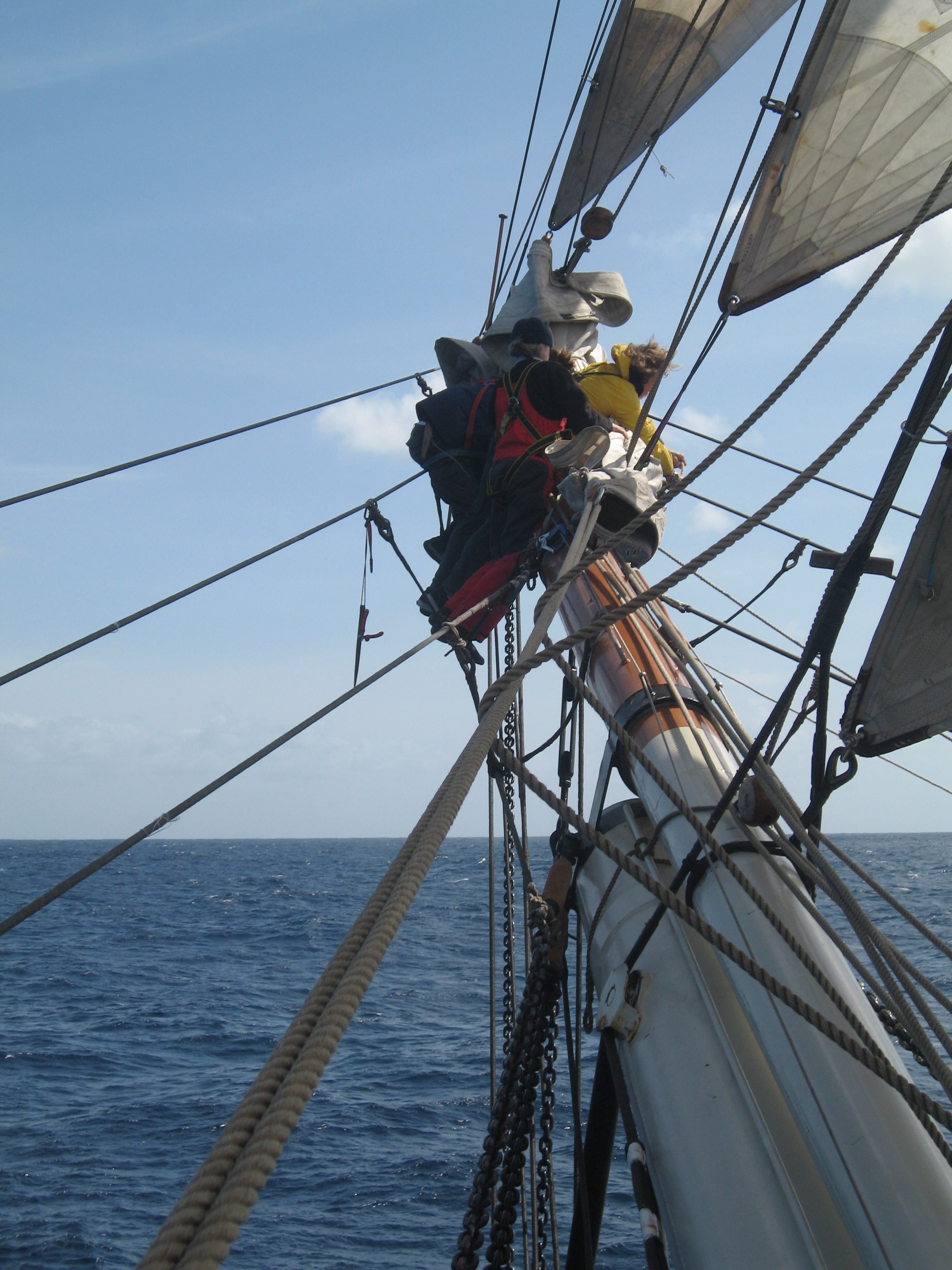
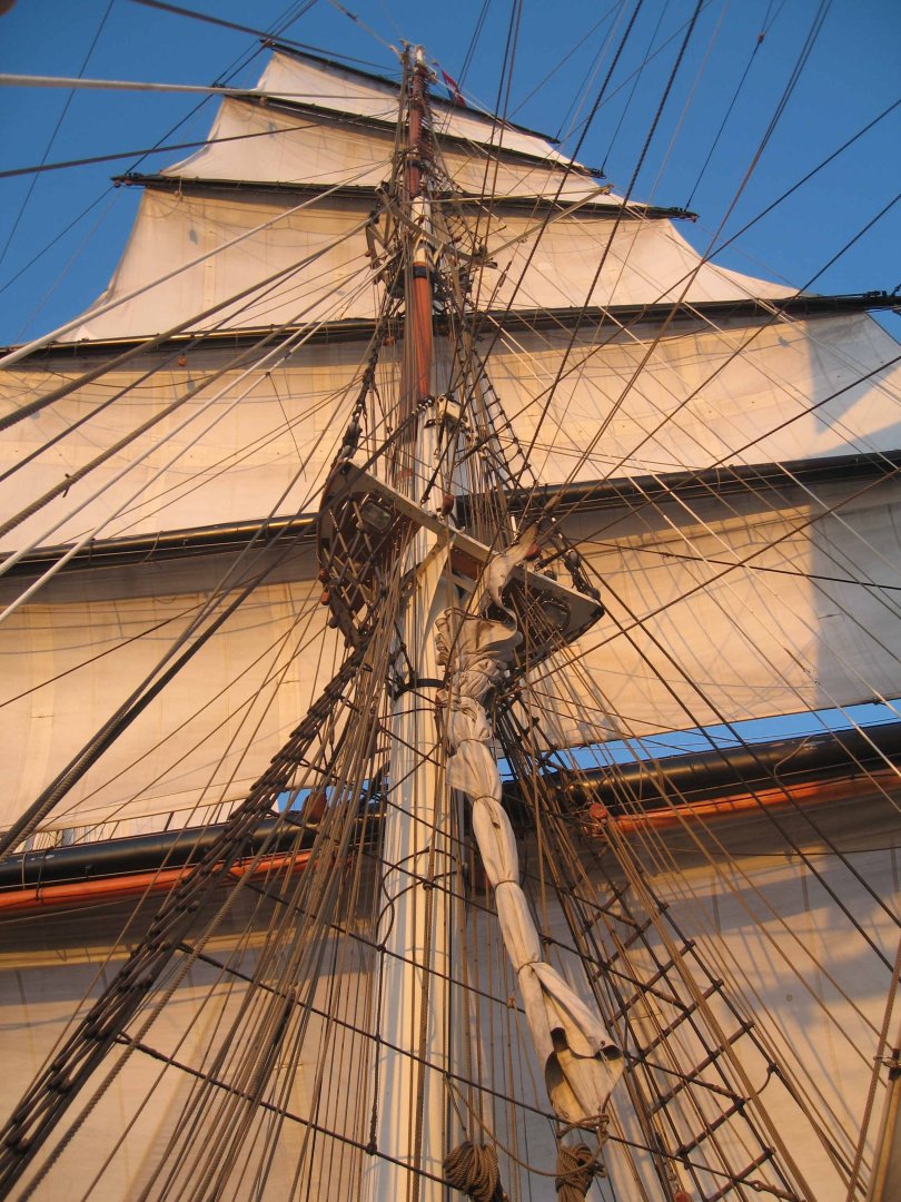
And you did a great job! Your fore topsail is a very nice, subtle approach towards the way that older sails set. Not many artists captured it but, in rather light weather, the weight of flax/hemp sailcloth made the sail hang down from the yard, then balloon forward near the foot, where the force of the wind overcame the lesser weight pulling down. You have captured that shape, though not so extreme, hence better suited to the cotton canvas of a clipper. But I don't see how a forecourse can be well modelled. There's no way to reproduce the way that the wind lifts the sail, against its own weight, when the only solid connection is along the yard. No criticism there. I just don't see how, mechanically, it can be done. Trevor
-
For realistic sails, there's nothing to equal the real thing 😀 That's Stad Amsterdam, with a sailplan close to a 7/8 copy of Cutty Sark's, so not a Yankee clipper but not so very different either. The image on the left was taken with a wide-angle lens, which has messed with the perspective. Trevor

-
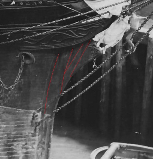
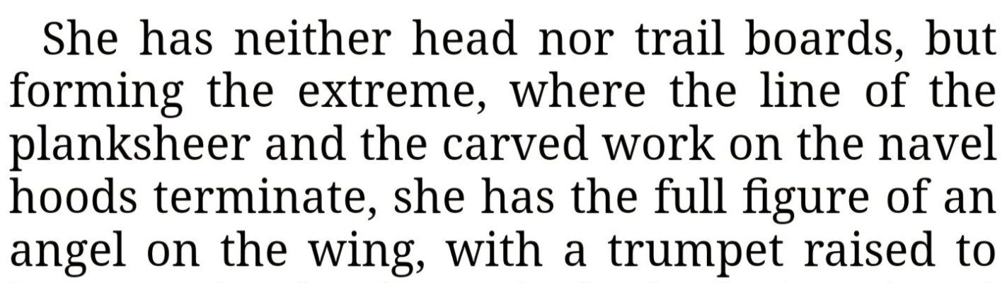
You gentlemen are generating posts far faster than I can hope to respond to them! But before attempting to catch up: Rob: It is all too easy to get lost in discussing the fine details of long-gone ships. None of that should distract us from your absolutely awesome model of Glory of the Seas. Every time I look at your images, I am stunned by the quality of your work! Please don't let any disagreements overshadow that achievement. Now ... I don't think that anyone has suggested that the 18th Century type of navel hood had a place on a clipper (as in "clipper ship", not so sure of the Baltimore clippers). At least one contemporary commentator used the term for a quite different structure on the bows of Flying Cloud and you have extended that into a term for a modified version of that same structure on Glory. But neither conforms to the older dictionary definition. I hope we can agree that understanding some long-ago document requires that we both follow its words and understand its context. From what I can see, McLean was extolling the virtues of a particular ship, for an audience who understood ships, but not providing instructions to shipwrights who might build a similar vessel. Hence, he did not have to be fully precise. He wrote that the angel was "where the line of the planksheer" terminates, not at the end of the planksheer itself. I take that to mean that extending the curve of the planksheer would lead to the location of the angel -- which makes complete sense and fits with such other evidence a you have presented. It is less certain what McLean meant by "navel hood" but the paintings of Flying Cloud (unlike the photographs of Glory of the Seas) suggest that the carved (and gilded) work on those "hoods" dropped down as it flowed aft from the feet of the angel. My guess (though there's plenty of room for disagreement) is that the lower, after end of McLean's "navel hood" surrounded the hawse hole (as the old, original type of navel hood had on other ships), while the upper forward end stretched out meet the forward reach of the stem structure, where the latter bore the angel. I'll also try to respond to: But not right away! Trevor
-
pin vise and drill bits
Kenchington replied to palmerit's topic in Modeling tools and Workshop Equipment
Lee Valley's catalogue can have that effect. There is no known antidote, except for enforced abstinence. But at least you are safely distant from the temptations that await anyone who enters one of their stores 😀 -
True enough. And he also says nothing of where the navel hoods terminate, only where the carved work on them terminates. Like Scott, I read where the carved work terminates to mean that there was no navel-hood carving beyond the aftermost part of the angel (i.e. the feet), though I don't deny that there is some ambiguity. But you are right that the structural timber of the navel hoods could have continued up to the angel's shoulders, as in Glory. Certainly, there was some sort of heavy timber there. As you say, the figure could not have been supported by its feet alone. (And I see to justification to suggest some sort of supporting ironwork, though that would have been technically possible.) Trevor
-
Steady on, Rob! As I have pointed out before, that is a reference to the hood ends of the planks and nothing whatever to do with the navel hoods, either in the original meaning of that term or the unique McKay structure. Yes. But that is the upper, forward end of the structure in question. My point concerned the lower, after end. From the quoted text, that seems to have surrounded the hawse holes in Flying Cloud but, as seen in photographs, it clearly did not in Glory. Because, I suspect, in Flying Cloud the structure was as McLean described it and stretched from hawse holes to the feet of the figure, whereas in Glory it reached from above and forward of the hawse holes out to the figure's shoulders. You have not (yet) offered evidence that McLean used the "navel hood" term for the McKay structure as it was in Glory, though it is a convenient one for modern discussion of the unique McKay structure. As so often with complex nautical technology, we can get confused between things and words. What "is" is the structure that McKay seems to have included in the bows of his clippers, apparently with evolution of its details from ship to ship. "Navel hood", in the generally understood meaning of the term, is something right around the hawse holes. Originally, it was there to take the wear and tear of the cables but hawse holes were not infrequently decorated and shipborne decorations often took the name of the structural piece that underlay them. I'm not surprised if some people took to using the "hood" term for the decorations around the holes. With no known term for the McKay structure and an example of it, in Flying Cloud, that stretched up from the hawse holes, McLean seems to have adopted the "navel hood" term for the whole thing, right up to the feet of the angel. Which (to mix my metaphors in a poor attempt at a pun) has left us arguing over how many of those angels could dance on the head of a pin! Trevor
-
I would agree with you, Scott, except for the wording that ClipperFan posted last night: So at least one contemporary saw the figurehead as placed where the carved work on the navel hood ended. Hence, the structure reaching out to the figure and underlying the carving was perceived as the navel hood -- albeit a very different structure from what that term was conventionally applied to. And that may well be a hint that McKay had come up with something different, something lacking its own term, that extended from the conventional navel hood into a substitute for archaic head rails. But that complicates things further with Glory of the Seas, as her version of the structure in question did not encircle the hawse holes at all. There seems to be agreement that we are looking at a signature feature of (maybe a feature unique to) McKay's ships. In Flying Cloud, it encompassed the hawse holes and was given the (not entirely appropriate) term "navel hood". In Glory, it ended above and forward of the hawse, so an evolving feature -- as you have said). Rob and ClipperFan have chosen to apply the "navel hood" term to all variants of the McKay speciality. Maybe there's something better that would more clearly identify the McKay structure, but I'm not going to be the one to suggest what that should be called! Trevor
-
You are very welcome! I doubt that is possible. Free-swinging means no glue. I used one nail and peened the end, forming a river-like arrangement. The kit-supplied rope (really a fine cord but rope at scale) is very slippery and does not hold knots well. You did well to pick Ashley's #290 as it is an angler's knot, chosen because it holds in the stiff, slippery lines typically used with road and reel. Half-hitch and glue should work but I got very annoyed trying to lash down the tack of the sail using the kit's material. For most else, I just pushed the kit-supplied cordage aside and used better material. From what I see on MSW, that's often the best solution with even high-quality kits. Skimping on cordage seems the first way to economize for many manufacturers. If the hole is little larger than the line passed through it, a single overhand knot is fine. For a rather larger hole, use a figure-of-eight (Ashley #520) for seamanlike neatness, though two overhand knots will do just as well, if the second is tied on top of the first (not two knots in line, each as thick a the other), so long a they are tucked out of sight -- such as under the stern quarter knees of the pram!). Ashley has many alternatives for still-larger stopper knots, though most would not be practical in a model. Trevor On the endless learning about ships, seamanship and seafaring ... The professionals would tell you that, even after a lifetime at sea, they never stop learning. The rest of us can only struggle along in their wakes. But a lesson for today: "Rope" is a material. Once some length of it is cut off, given whatever treatment it needs (ends spliced around thimbles, perhaps), at sea it is rarely "a rope" and more often "a line" (as well as having its own name, such as sheet, shroud, stay etc.). There are "ropes" on shipboard, foot ropes, manropes and the like, but generally "rope" is a material from which "lines" are made. But not everything that looks a bit like rope is properly called "rope". At the upper end, there are cables (made by twisting ropes together) which are arguably not "rope". At the lower end, there are sizes that cascade down through cords to twine and threads, which nobody would call "rope". That gets even more difficult with models, as a heavy cable at full size gets represented by a thin cord at scale. I tend to fall back on calling the whole lot "cordage", which does for everything from twine to cable at full size. (I doubt that anyone would call sewing thread "cordage", until it is used in modelling as a representation of cord.) Enough pontificating for one morning!
- 55 replies
-
- 3
-
-
- Norwegian Sailing Pram
- Model Shipways
- (and 2 more)
-
I hope you don't, Rob! Requests for clarity in your account of what you have found and for your evidence shouldn't be disheartening. Not half as much as your discovery will be to all of those people who have built models of McKay clippers and must now face the probability that those models are badly wrong 🥲 Sometime soon, I may finish an extended essay on Sovereign of the Seas (the 1638 one) which, among other things, will argue that just about every model yet made of that remarkable ship has very badly misrepresented the prototype. I'd say they are all "laughably wrong", except that I see no amusement in demolishing the achievements of others. How many thousands of people (many far more skilled than I will ever be) have spent how many millions of hours, and millions of dollars, on those models? Yet I can't find even one that I wouldn't dismiss at a glance. That's a lot of people who have reason to be disheartened. I think what you are saying is that the arrangement clearly seen on Glory of the Seas, which you (and I think you are saying that it was you, in the plural) have called a "navel hood", was a McKay signature feature, used on many (all?) of his clippers but not by other builders. I'm assuming that you have reviewed the available evidence, so I'll accept your conclusion. (I'm certainly not about to repeat your research!) The structure is clearly more than just decorative and provides enhanced lateral support for the uppermost part of the stem -- far more support than Great Admiral had, to cite only ClipperFan's recent example. Do you think it may also have given some extra lift when the ship plunged into a head sea -- as a step towards the flare that could more easily be built into a steel ship than a wooden one? Yet, as I have argued before, there was nothing secret about that navel hood. It was right there before the eyes of every sailor and shipwright in every port that a McKay clipper visited. So why wasn't it replicated by other builders? Did others not see the point? Or was it professional courtesy and professional pride, discouraging each builder from copying a fellow artist's signature? Maybe there is a comment in a letter or notebook somewhere that could provide answers but I rather doubt that we can ever know. Trevor
-
That I can answer. You "bend" a sail to a spar. That's true whether you use a continuous lacing, as in the pram, or separate lengths of twine or rope at each eyelet or cringle, which is normal for large sails. If the lengths are separate, they are called "robands", probably a shortening of "rope bands". Trevor
- 55 replies
-
- 4
-
-
-
- Norwegian Sailing Pram
- Model Shipways
- (and 2 more)