HOLIDAY DONATION DRIVE - SUPPORT MSW - DO YOUR PART TO KEEP THIS GREAT FORUM GOING! (Only 51 donations so far out of 49,000 members - C'mon guys!)
×

Kenchington
-
Posts
679 -
Joined
-
Last visited
Content Type
Profiles
Forums
Gallery
Events
Everything posted by Kenchington
-
 That was my guess before I started and I'm reinforcing the notion as I go forward. How much it matters depends on the kind of model, of course. At one extreme, a diorama with crew figures on board can go badly wrong if you don't know what the people on board the full-size prototype did -- and what they did under what circumstances. (A Dreadnought battleship at anchor might have officers strolling on the quarterdeck but they would not be there as she steamed towards Jutland. Nor would common seamen be lounging about in the exclusive preserve of the officers, even in harbour!) But I think that even a simple model of a simple boat, such as the pram, will benefit from the builder understanding what the people who own, maintain and sail the full-size version do. And not only what they do but how and why. Trevor
- 167 replies
-
- 3
-

-
- Norwegian Sailing Pram
- Model Shipways
- (and 1 more)
-
Fascinating to see a 3-dimensional interpretation of one of these ships! It's one thing to re-draw ancient vase images in 2D but quite another reproduce a miniature in (approximately) the original materials. Trevor
-
I am glad you found it useful, MBerg! I don't like to come over as lecturing to MSW members, so many of whom know far more than I do about ship modelling. But if anyone finds my postings helpful, it makes them worthwhile to me. Trevor
- 167 replies
-
- 4
-
-
- Norwegian Sailing Pram
- Model Shipways
- (and 1 more)
-
Thank you, Mark! But I still have to make the tiller that you already endorsed, sight unseen!
- 167 replies
-
- 1
-
-
- Norwegian Sailing Pram
- Model Shipways
- (and 1 more)
-
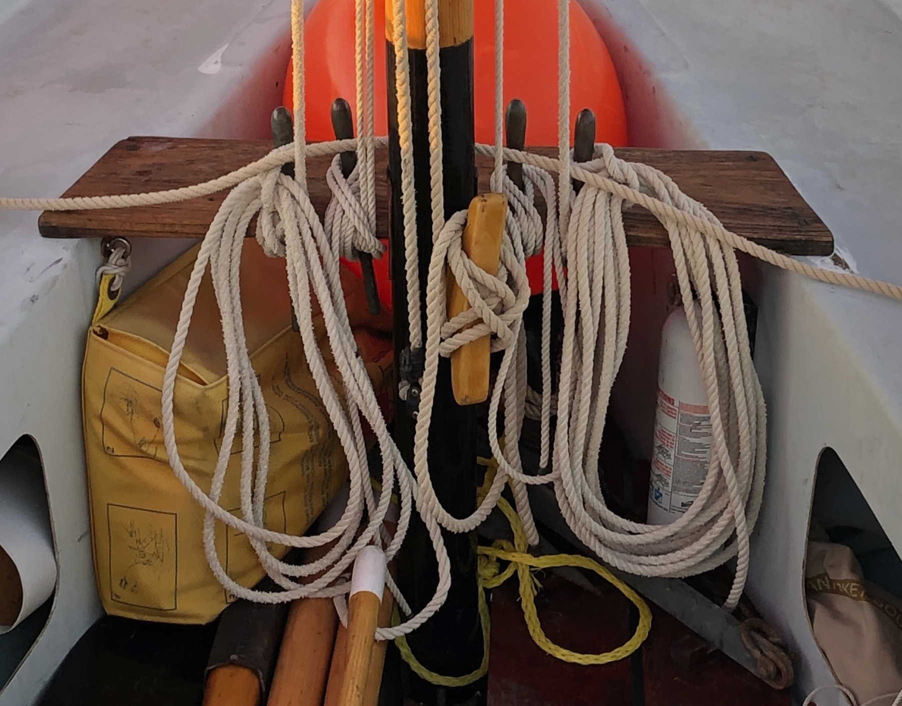
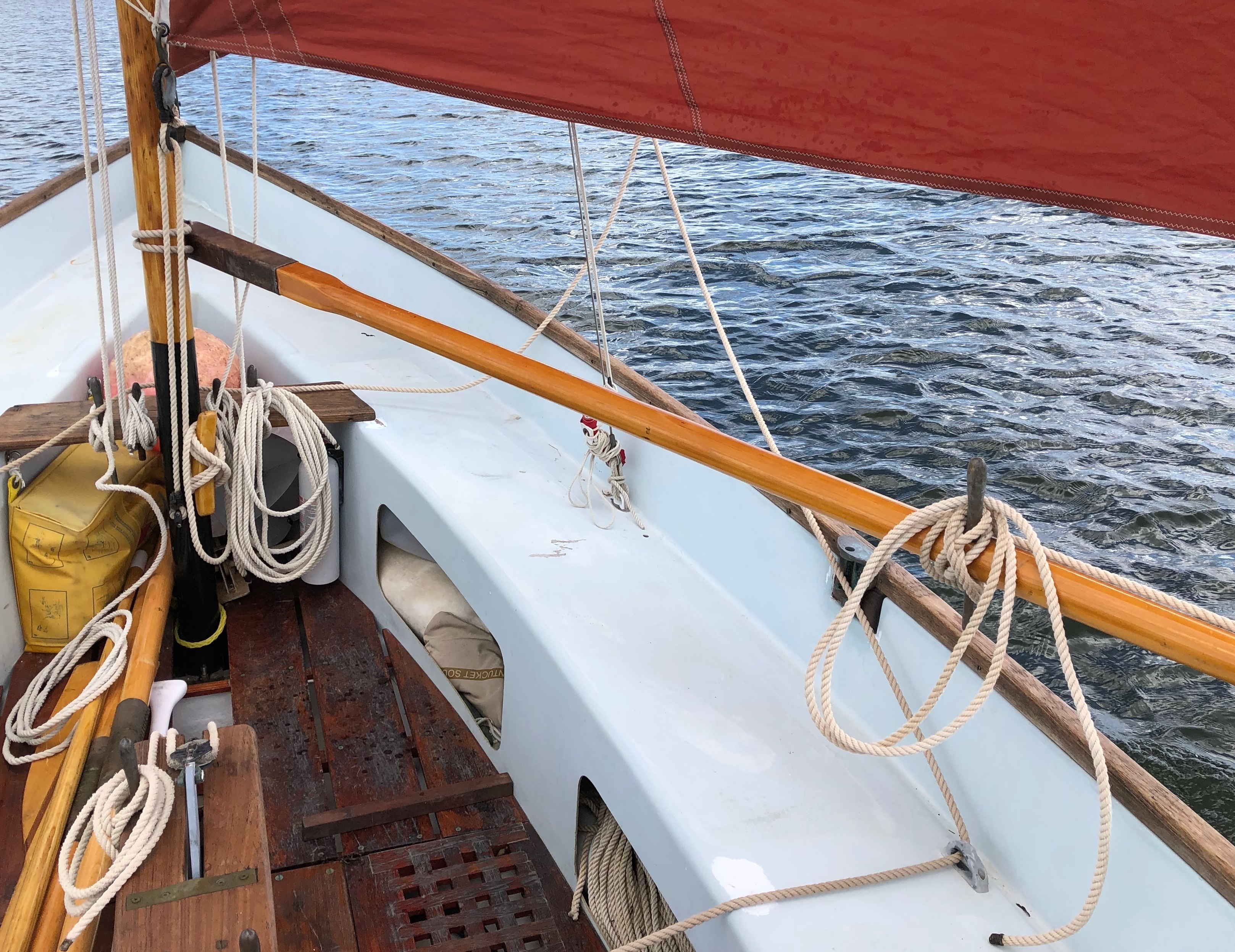
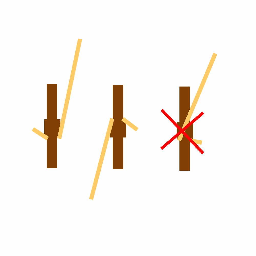
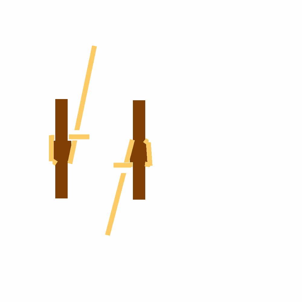
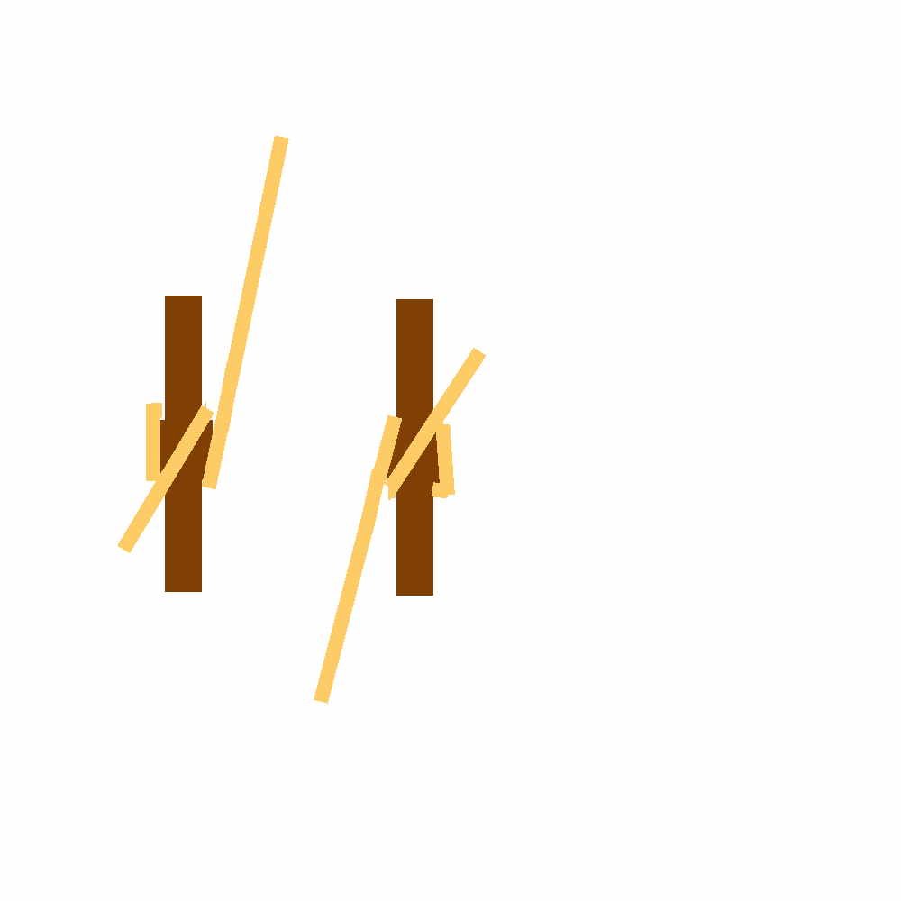
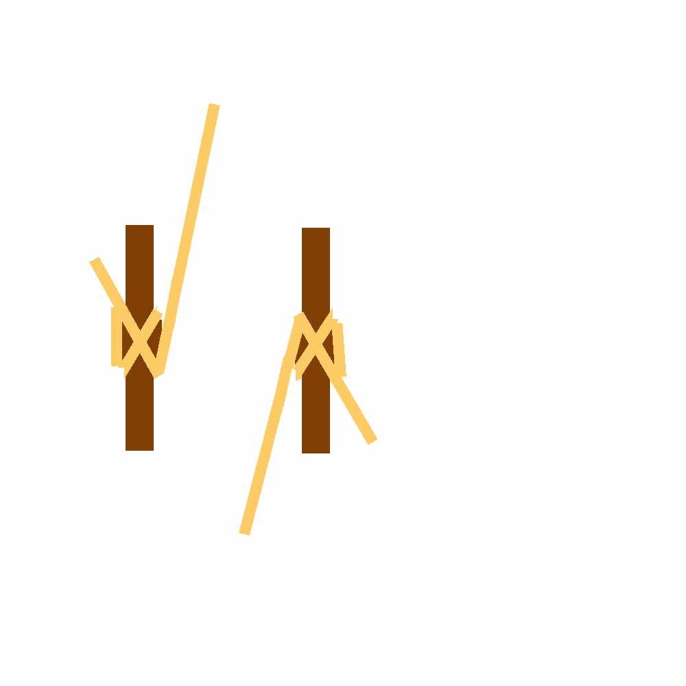
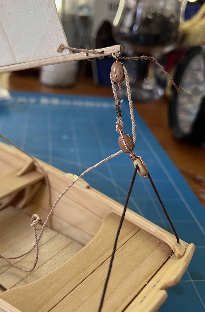
I am trying, in this build log, to provide a practical dinghy-sailor's perspective, to help those future builders of the pram who do not have direct experience of such boats. As my last post included all of the belaying of the pram's (very limited) running rigging, maybe this is a good time for me to add something about belaying lines to either (horned) cleats or pins. As with anything else, there are right and wrong ways to do it, hence right and wrong ways to show a belay in a model. There are other things that lines can be belayed to, such as timber heads or bitts, so the overall topic is large, but keeping things (relatively) simple, there are three "rules" for a belay to a pin or cleat. The first is absolute and should never be broken. It is that the line, on being brought to a pin, should pass cleanly to and around its top or bottom and never across the middle: That's not some fetish. Done right, quite a light grip on the line (the short end in that diagram) will hold a considerable load (at least with high-friction hemp or manilla, maybe not with slippery, modern Dyneema or Spectra), yet a gentle easing will veer some line if you have pulled too far, while you can readily catch and then hold some slack, if your shipmate is sweating up the line. Rule 2, to be followed any time that it won't force a violation of the Rule 1, is that the first pass of the line behind the top of the pin should be from left to right: OK, that is partly just a fetish but the idea is that, on a dark night, someone releasing the line gets a bit of a tactile warning that it is close to coming free, hence to be ready to take whatever load is on the line. Rule 3, to be followed when possible without violating Rules 1 & 2, is that the first turn around the pin should be a round turn, with no crosses (as shown above). If the rigger who set up the boat (or ship) did their job properly, all three rules should be followed, and should fall into place easily, in most cases. However, that cannot always be done, whatever the skill and care of the rigger. The clew outhaul on my pram, as I have it rigged, cannot be belayed according to Rule 3 if Rules 1 & 2 are obeyed. It could have been if the sailor was left-handed and the cleat on the port side of the boom. A right-handed sailor, pulling the clew towards the end of the boom, will naturally want the cleat on the starboard side. It has to be on the boom, of course, hence necessarily below the level of the clew -- and that orientation prevents all three rules being followed simultaneously. There is no such compulsion with the halliard or tack downhaul, which can be belayed following all three rules. Next, after getting to the point shown above, the line should be taken diagonally across the pin: then behind the pin and diagonally the other way: and repeat so that there are two diagonal passes in each direction. And that's it. No need to build on layer after layer of turns around the pin -- unless you're working with Dyneema (or, in a model, the lousy, slippery cordage that Model Shipways provide!). Though, if the tail of line is long enough to trail on the deck but not long enough to coil, you could take an extra couple of turns to use up the length neatly. The end result looks something like: Note that bringing lines down from the masthead to pins both port and starboard means that Rule 3 has to be ignored on the starboard side. Ditto for the tack downhaul, with its cleat displaced to the starboard side of the mast (and note also that that is placed at a slight angle, to make fulfilling Rules 1 & 2 more natural for the sailor's fingers). If you are working with the sizes of rope usually found on a sailing ship, even those on my 22 footer, there is literally nothing more to be done (aside from coiling -- which is a whole other topic). In a small boat like our pram, however, you can't rely on gravity to hold the loose end of the line in place. Besides, you may get a lot of water on board and that can wash a line off its cleat. So it can be a good idea to create a locking turn by passing the end of the line under the last diagonal turn -- as with the gantline on the pin next to the mast on its port side in that photo. (That has both ends of the gantline on the same pin, hence the double appearance.) At full-size, there's no need to tuck the long end of a halliard, say, under the diagonal. Rather, the last pass around the top of the pin is given a twist and dropped over the pin, leaving the locking turn. And that's all there is to it ... aside from working with forceps to pass miniature lines around model belaying pins, then repeating the process a hundred times for those who aspire to build full-rigged clippers 😀 Trevor

- 167 replies
-
- 7
-
-

-
- Norwegian Sailing Pram
- Model Shipways
- (and 1 more)
-
It will depend, amongst other things, on what effect you are aiming for. If I was going to build full-size Norwegian prams for sale and wanted a model that I could display at boat shows and the like, I think the Model Shipways approach would go well. The sail comes out as a flat, rigid board but that would still show off the advertised product. On the other hand, if I wanted a diorama of the Muscongus Bay sloop, with her owner/skipper hauling his lobster traps, I would want the sails either curved and full of wind or else shivering and shaking, as the sloop rounded up into the wind and shot alongside the buoy marking the next trap. Soaking cloth in diluted PVA wouldn't work for that. One day, I hope to build a Vanguard Erycina, with her trawl on the rail and her other fishing gear on deck. If that became a diorama, maybe I would have her at anchor, waiting on a wind, with sails furled. They would certainly need to be dyed, to simulate dressing of the canvas, but maybe that would be the only treatment required. As for Ranger (and with all respect for Chris Watton and his magnificent kits), I would question whether her sails should be dyed at all. Robert Hewitt (head of the company by the end of Ranger's career) wasn't just a fishing boat owner. He was a noted racing yachtsman, a one-time Commodore of the Prince of Wales' Yacht Club and later Rear-Commodore of the Royal Thames Yacht Club, while the Prince of Wales (the future King Edward VII) was Commodore. When (in 1864) Hewitt re-structured his company (what would now be almost a reverse-takeover), to raise enough capital to build steam cutters, he had sufficient connections in the right places to persuade Lord Alfred Paget to be Chairman of the new company. Besides being another member of the Royal Thames, Paget was a Member of Parliament, an officer in the Horse Guards and Queen Victoria’s Chief Equerry – as well as a son of the late Marquess of Anglesey, commander of the Allied cavalry at the Battle of Waterloo. Another of the Directors was Rear Admiral George Wellesley, soon to be appointed Admiral Superintendant of Portsmouth Dockyard and later First Naval Lord. Wellesley was a nephew of the late Duke of Wellington, the victor at Waterloo and briefly Prime Minister. When Hewitt's cutters proudly sailed up the River to Billingsgate Market, with fresh fish from his fleet out in the North Sea, all packed in ice (an innovation his father had brought in around 1850 -- then a first for European fisheries), those vessels were mobile advertisements for the family company and the men who led it -- led it to familiarity with the highest in the land. So I suspect, though I cannot prove, that the cutters sported "classy" white sails, distinguishing them from the spritsail barges and other such lesser craft that crowded the River, there being an unspoken but potent social hierarchy in such things. Indeed, as America had introduced English yachtsmen to the advantages of cotton canvas in back 1851, I'd not be surprised if, by the end of her time as a cutter working with the Short Blue fleet, Ranger's sails were bright white, rather than the creamy tone of conventional flax & hemp sailcloth. Trevor
-
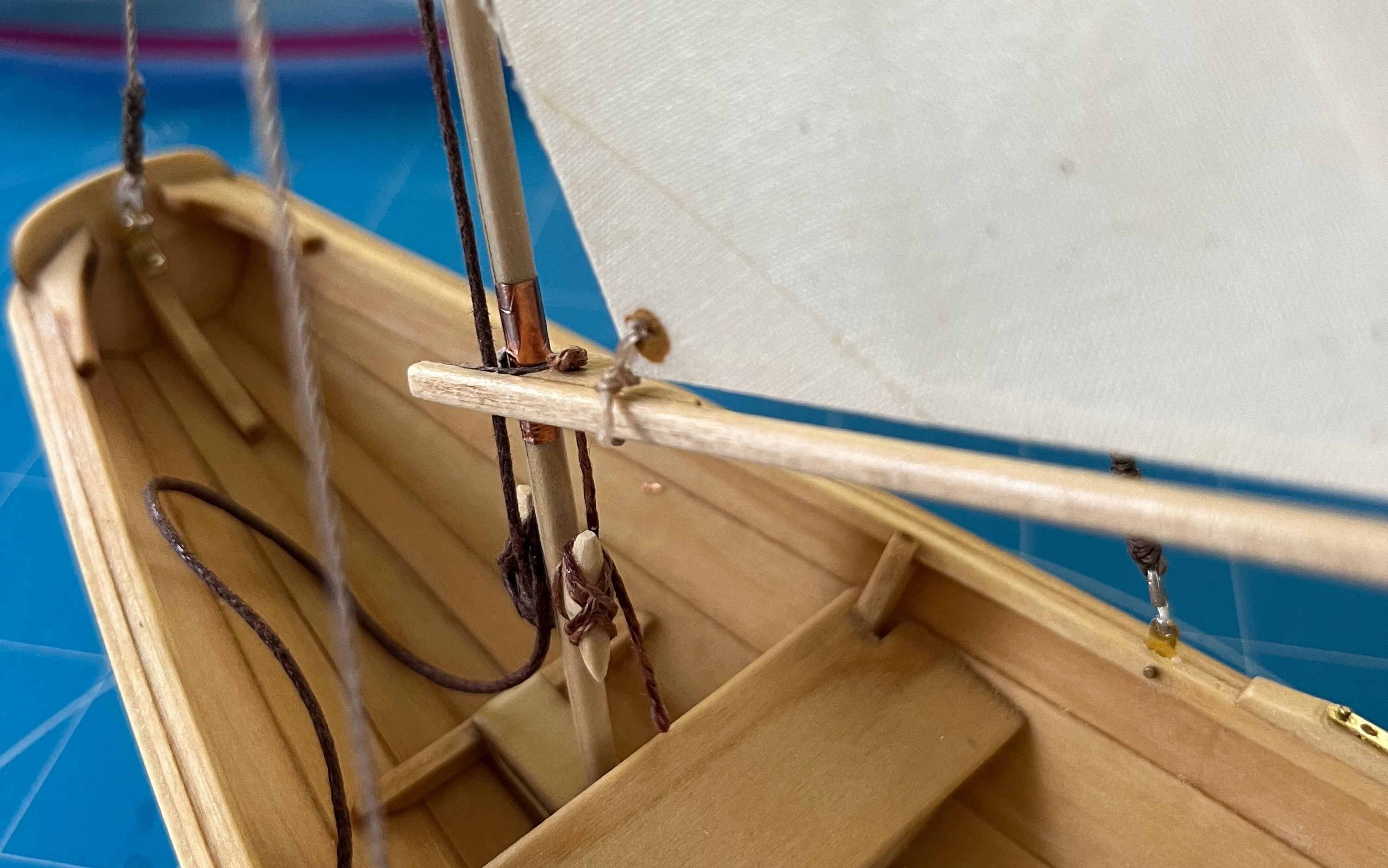
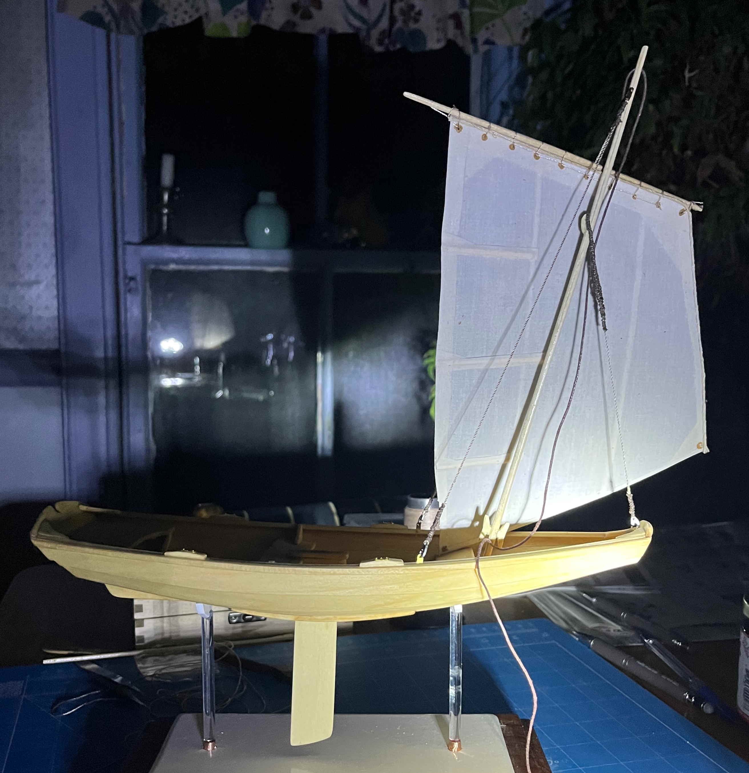
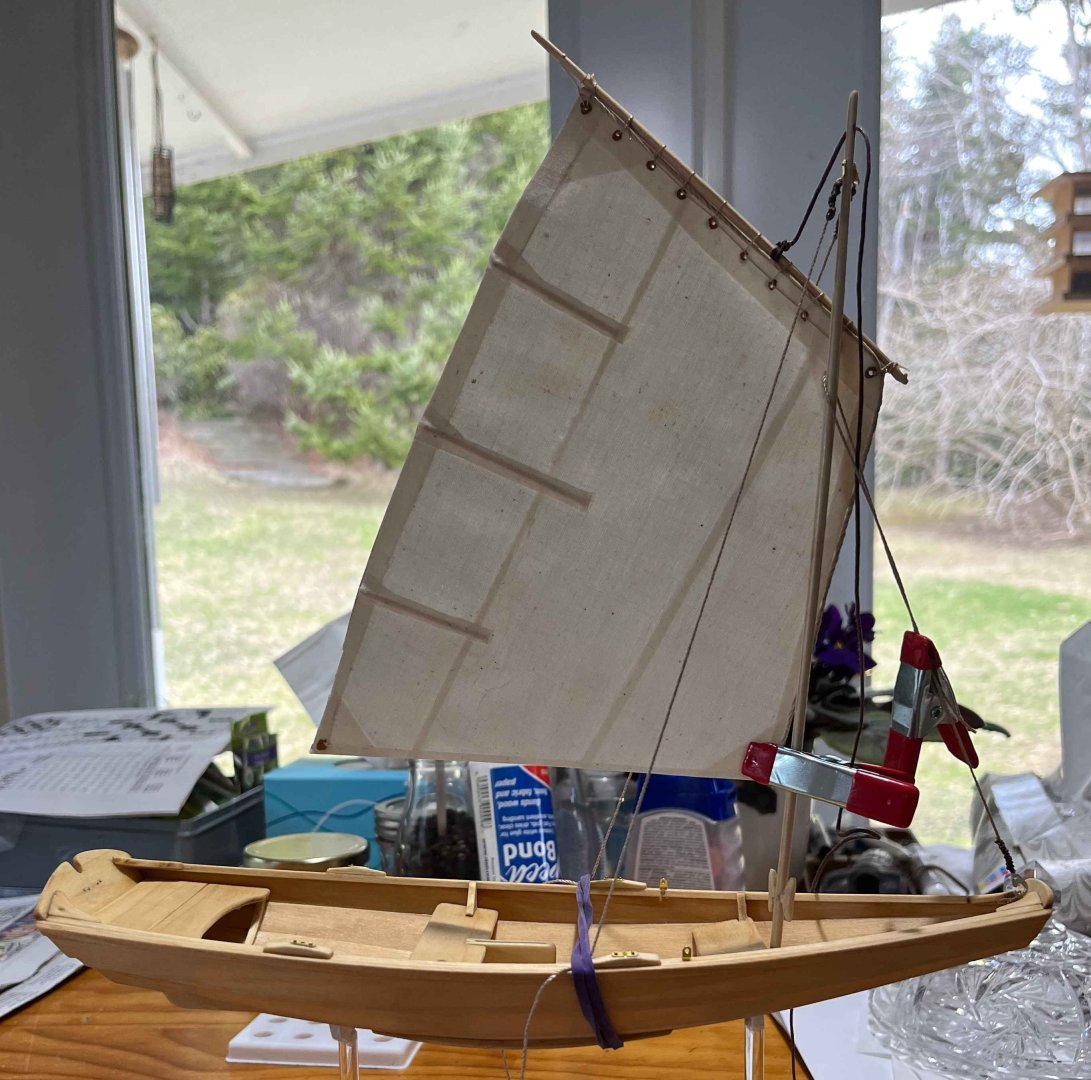
Thank you for the "wow", King Derelict! Not sure that is deserved but it's welcome all the same! Today: Setting the sail: There was one point in the kit instructions' suggestions for the mast that I had skipped over: There is to be some "copper" applied where the boom jaws bear against the mast. I hadn't forgotten that but other build logs have reported trouble when the "copper" was applied while building the mast and the boom later rested higher or lower. So I wanted the boom in place first. The instructions suggest representing the "copper" with painted paper. I know that some model builders have used real copper, beaten thin then glued on. I opted for the simpler alternative of using a tiny piece of adhesive-backed copper tape. In the end, it hardly matters as the piece can barely be seen around the mast jaws. With that done, I could set the sail properly. The instructions talk about belaying the tack downhaul first, then the halliard. That's a bit of a reversal, as the halliard has much more scope for adjustment, so you need to fix that first, thus setting the height of the sail up the mast, then do the tack downhaul. (At full size, hauling on the halliard is a fight against gravity and friction, so best not done when also fighting tension in the rig. In contrast, it is easy to throw your body weight onto the boom, get as much tension as you wish in the luff, then belay the downhaul.) There was really no difficulty with either in the model, except that even my larger mast cleats were too small for the material I had chosen for the halliard. I had to glue turns onto the cleat before adding more turns. Full-size, the downhaul needs no more length than needed to belay on the cleat, so that one can get clipped off short. The halliard has to be long enough to drop the sail and yard into the boat, of course, so there's a whole lot of extra length around. I will have the "fun" of coiling the excess later. In the meanwhile, all looks quite nice: I fastened one end of the sheet to the "becket" on its lower block by the same CA-glue and sail-twine whipping approach (masquerading as a served splice) that I had used on the standing rigging. This time, I worked with the sheet loose in my hand and put on a common whipping (rather than a westcountry) to see whether that would be less lumpy. Then I passed the rope horse through the traveller block and put the ends through the holes in the stern quarter knees (which had to be re-drilled first), tying figure-of-eight stopper knots in the hidden ends. I made the horse much longer than I had expected to as I wanted to be sure that it would always clear the tiller. Maybe I will shorten it later. That will be easy to do, if necessary. The sheet has to be long, as it must span twice from the horse to the boom end, when the boom is freed off against a shroud, with yet more length to bring its end to the hand of someone sitting amidships. All of that length had to be rove through the boom-end block, then through the one "shackled" to the horse and everything pulled gently taut: There's tidying up still to be done (with the end of the clew outhaul, in particular) but I'm happy with how it's going. And that crazy forward rake of the mast doesn't look so crazy now, with the limited space between boom and hull. Trevor


- 167 replies
-
- 6
-
-
- Norwegian Sailing Pram
- Model Shipways
- (and 1 more)
-
pin vise and drill bits
Kenchington replied to palmerit's topic in Modeling tools and Workshop Equipment
The pin vise that came with my Model Shipways combo was almost useless but I baulked at the price of the Starrett. I picked up a much cheaper one at my local hobby store and it has not let me down yet. I'm not certain but I think it is the Excel one -- $20 Canadian here and probably available for much less where you are. I can't offer any advice on drill bits, though I see that Otto Frei sell them in packs of six of the same size. They must expect their customers to break bits frequently! Trevor -
I don't think I have ever seen (full size) dory oars leathered. For one thing, there's not much need, when they are worked between (rather soft) thole pins, versus metal crutches. For another, in the days when dories were rowed in the ordinary course of a day's work, the oars were disposable items. (Even the dories did not have long working lives, when battered about on the decks of schooners.) Each to their own, of course, but I didn't leather the oars of my dory model. I will leather the ones I put into my pram. Trevor
- 71 replies
-
- 1
-
-
- grand banks dory
- midwest products
- (and 2 more)
-
Really nice paint job! Too many look rough when viewed close up but yours looks great. Trevor
- 86 replies
-
- 4
-
-
- Model Shipways
- Norwegian Sailing Pram
- (and 3 more)
-
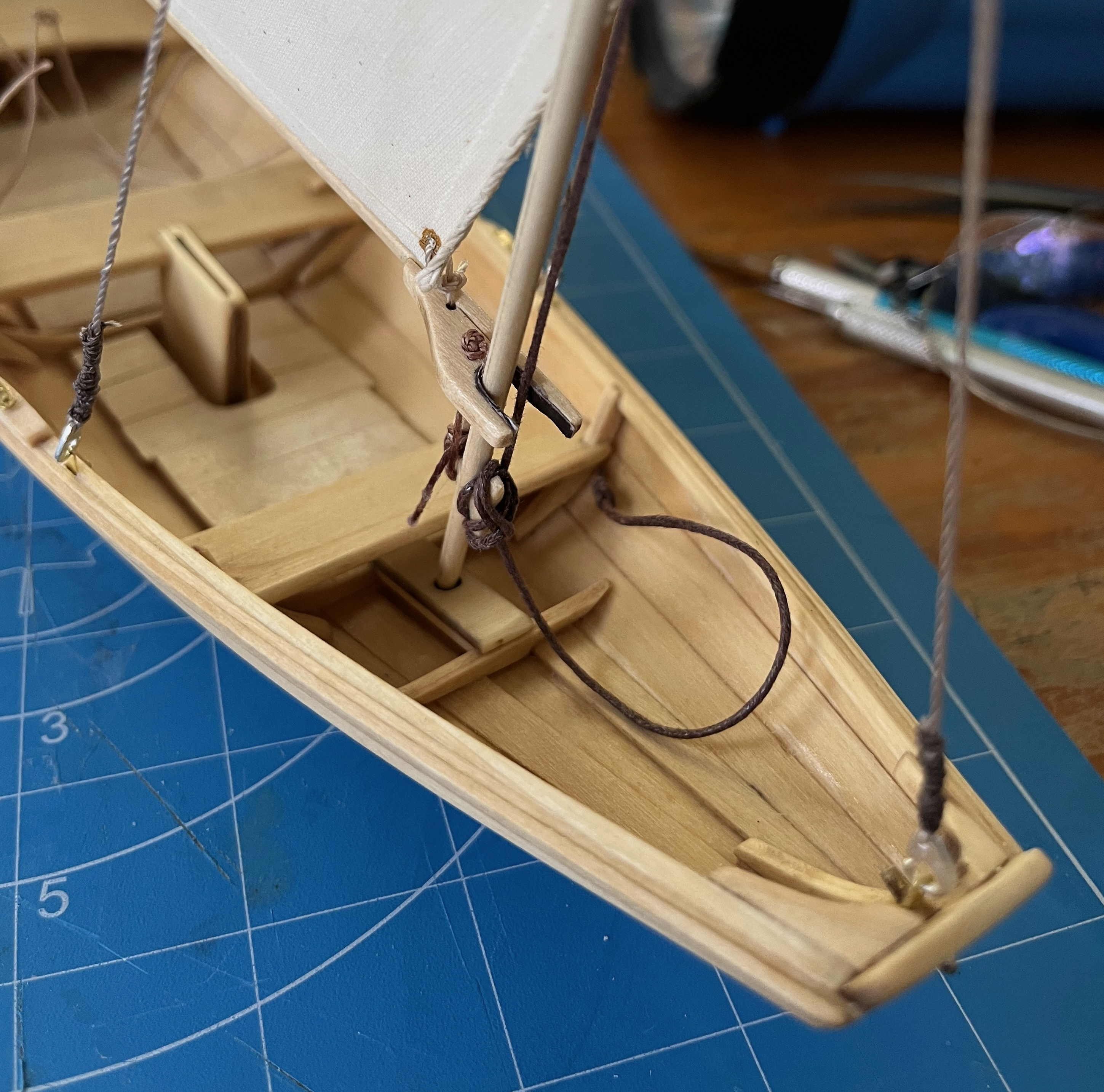
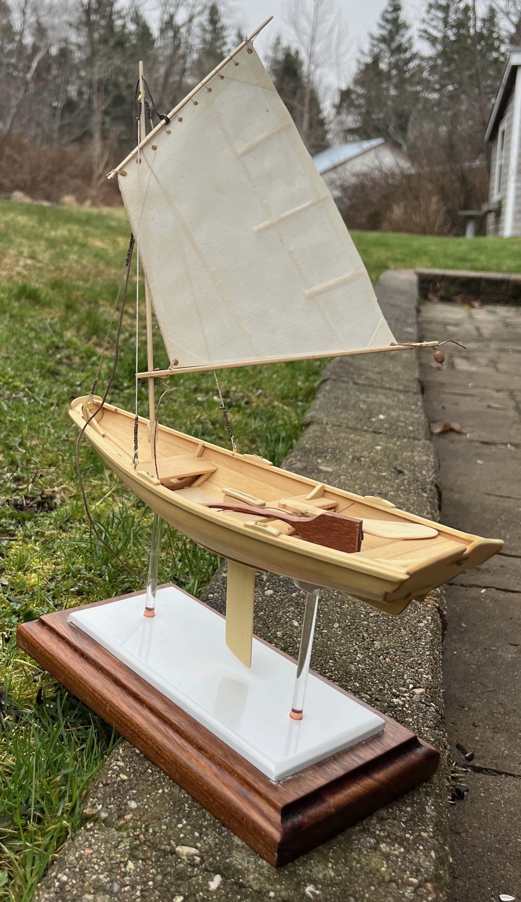
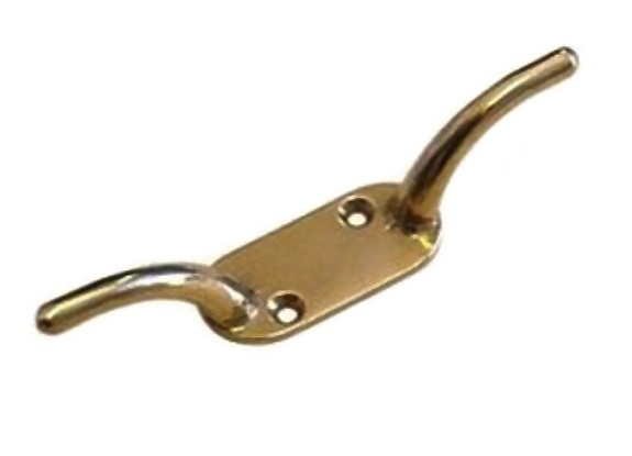
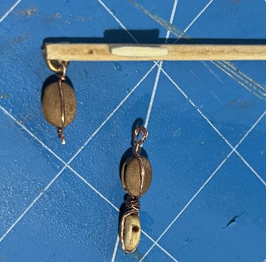
Boom, phase 3: Clew outhaul Last night, I was troubled over that split cleat. If I made another one the same size, it would suffer the same fate. If I made a bigger one, it would be ugly and clunky. Then, first thing this morning while still three-quarters asleep, it came to me. I needed a very different kind of cleat. I needed one of these: They are ugly too and really only fit for clotheslines and the like, though that image came from the website of a yacht chandlery, where the thing is presented as suitable for a flag halliard. Yet it is described as 5 inches long. (Mighty big flag to require a halliard that size!) So it would be well suited to the task at hand and easy to represent in miniature. Drilled two holes through the boom, placed two of the kit-supplied copper nails in the holes, with a touch of low-viscosity CA. Once that had set, bent each nail over the tip of needle-nose pliers and then snipped off its point. Voila! Cleat for clew outhaul: I had previously rigged a length of 0.5 mm hemp cord, with a figure-of-eight stopper knot, and passed it through the "eyelet" in the sail (as in the image), and I had passed a lashing to hold the tack of the sail to the forward end of the boom. (A very annoying task, with the hyper-slippery line supplied with the kit.) So all that was needed was to pull the outhaul taut and belay on the cleat. Even at 1:12, that was easy and gave me: I'm not yet ready to belay the halliard, nor the tack downhaul, but the pram looks about ready to sail away anyway: Maybe next time I'll carry her down to the shore and get a more maritime background 😀 Tiller still to be worked on, of course. Trevor

- 167 replies
-
- 3
-

-
-
- Norwegian Sailing Pram
- Model Shipways
- (and 1 more)
-
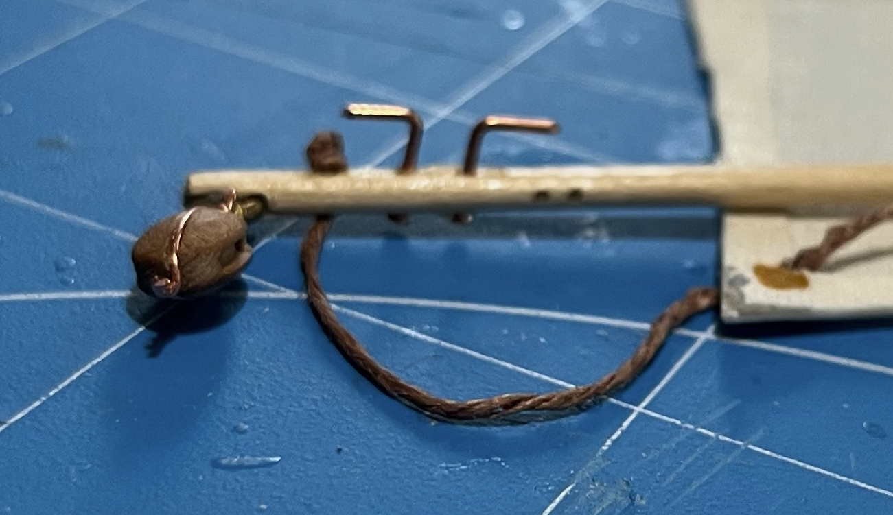
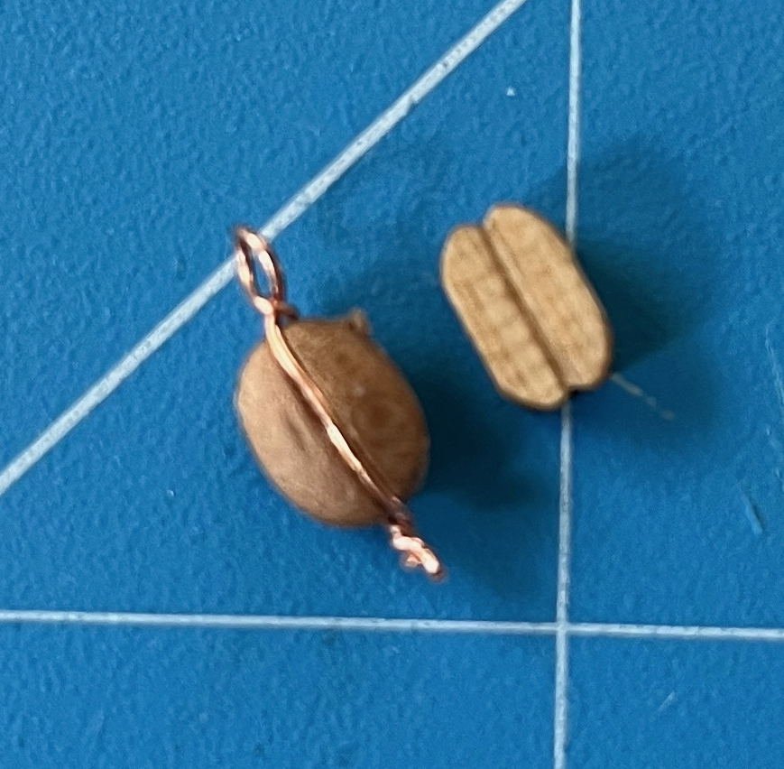
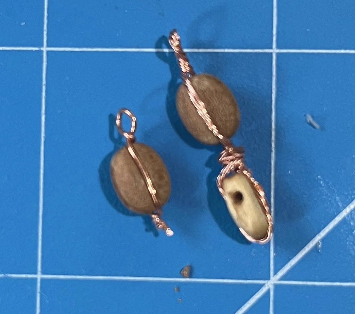
Boom, phase 2: Sheet blocks Two steps forward, one step back today. I got close to having the sail rigged but then the clew-outhaul cleat broke off the boom and, when I tried to drill it for a nail (to give a stronger attachment) , it split in two. Back up and start over tomorrow. But at least I can report on the sheet blocks. The mainsheet is the most complex bit of rigging on the pram -- the only thing likely to be adjusted during an afternoon sail and one that will be in constant use. The kit instructions call for one end of the sheet to be held in a curious slot in the end of the boom. From there, it is rove through a block on a rope horse (bizarrely called a "traveller", which should mean the thing that travels along the horse) at the stern, thence back to the end of the boom, then forward to above the midships thwart and down to the helmsman's hand. That's one way to rig a dinghy. Indeed, it's pretty much the same as the standard way that the original Laser dinghy is rigged (and that's still the most numerous design of sailing boat ever created, as far as I am aware). Having the end of the sheet amidships has some advantages in a racing boat, principally that the helmsman can face forward and see where the boat is going while tacking. But it's an annoyance in a purely recreational boat, with the sheet forever getting in the way, while any loose loop that may form under the boom is all too likely to strangle an incautious crew member! For the pram, I'd rather keep the sheet at the stern, aside from a length leading to the hand of course. Anyway, the implementation of that Laser-like sheet lead in the kit is dreadful. A Laser has two blocks under the boom and the sheet reaves through those. I'm guessing that the full-size pram has the same, with each block attached to the boom with a U-bolt. The kit, however, has dispensed with the blocks and kept only the two U shapes (made by bending brass wire). Worse, they are aligned along the boom, so not only does our miniature sailor have to deal with the friction of metal loops in place of blocks but also the extra friction of the sheet snaking through those loops -- while the sheet gets worn away by being dragged across small-diameter metal. Yuk! Worse still, the one block that is provided in the kit rides along the rope horse with nothing more than a metal loop (formed along with the stropping of the block) around the rope. That's a quick way to wear out the horse and have it part at just the wrong moment. Bad idea when on the water! So ... I decided to go with a sheet entirely at the stern, where I will have a traveller block riding on the horse. With such a small sail on the pram, the sheet only needs to have a two-part tackle. Some people would fasten the standing part to a becket on the traveller block, lead the sheet from there up to a single block on the end of the boom, then down to the helmsman's hand. I never liked that arrangement in my dinghy-sailing days: Lose hold of the sheet for even a moment and you will find its end dangling from the boom, somewhere far out over the lee side of the boat. Very, very annoying, when it isn't much worse still. What the pram needs, in my experience, is a single block with becket shackled to the traveller block, the sheet then rove from that becket, through the block on the boom end, back down to the lower block and thence forward to the helmsman. But that means three blocks, while the kit only provides one. In fact, it provides only a rather crude blank (though not as crude as the one illustrated in the instructions), while the model builder is encouraged but not required to "improve" its shape. Anticipating that problem, I had ordered some nice blocks of the right size. I could have used three of those but building the pram is supposed to be a learning experience, so I shaped up the kit's block and made it the traveller, while the two sheet blocks are store-bought. The kit includes some copper wire to bend into a strop for the one block provided. That proved to be a very easy process, once I picked up jewelry-making pliers (with round jaws) at Michael's. There was not enough wire to strop all three blocks but I have plenty of odd bits and pieces of discarded electrical gear, so I pirated some copper conductor, twisted up a bit of multi-stranded wire of the right diameter and stropped the traveller and lower sheet blocks together, with a twist of wire substituting for a shackle between two separate units. On the left is a store-bought block stropped as called for in the instructions (later to be the upper block, on the boom end), paired with the kit-supplied block as it came. To the right is the upper block again, paired with the combination of lower block and traveller block (the latter made from the kit-supplied one). I decided to attached the upper block to the boom using a U of brass wire, much like the ones that the instructions expect the sheet to be rove through. Annealing and bending the brass was easy. Enlarging the holes in the boom wasn't hard. But trying to dry fit the U into the hole split the end off the boom. Not a problem, as I intended to hold everything together with a dollop of CA anyway. The bigger challenge was keeping the loop on the block in the U, while the U went into the holes in the boom. In the end, I held all together with masking tape until the CA had set, then filed down the ends of U until flush with the top of the boom: and then: It looked quite nice at that point, before the cleat broke off! More tomorrow, when I have made and fitted a new outhaul cleat. Trevor

- 167 replies
-
- 5
-
-
- Norwegian Sailing Pram
- Model Shipways
- (and 1 more)
-
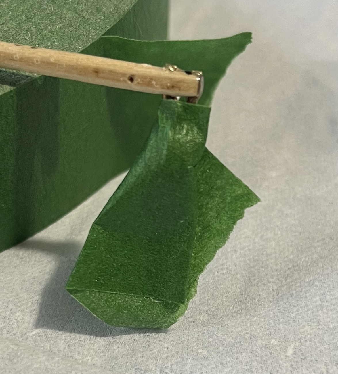
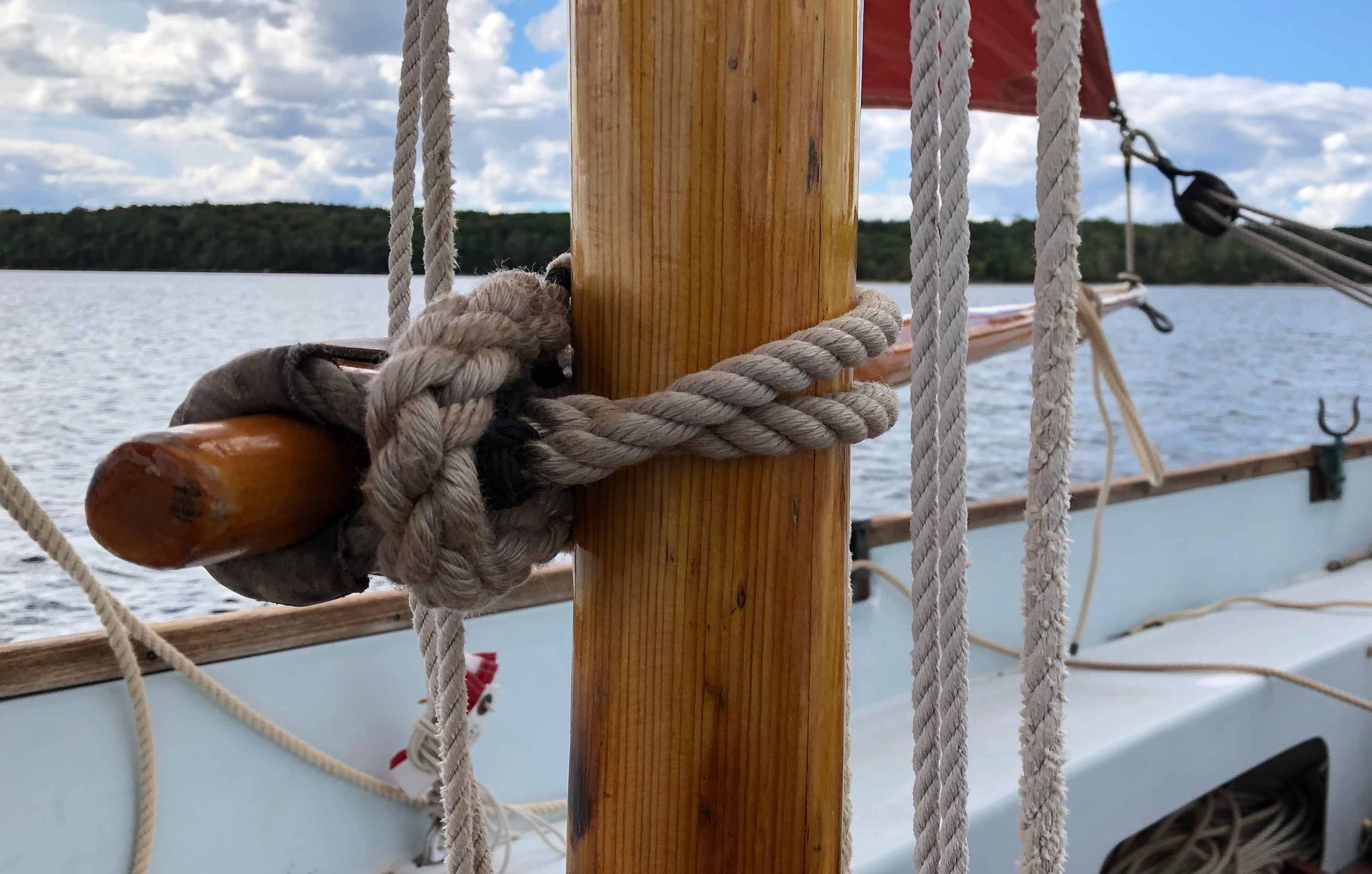
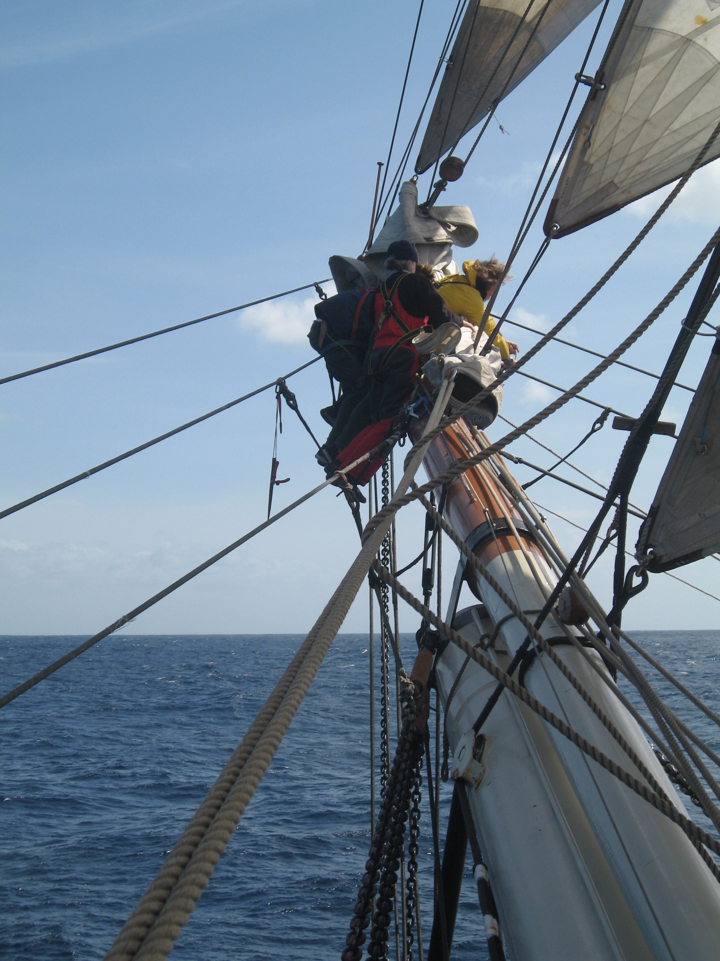
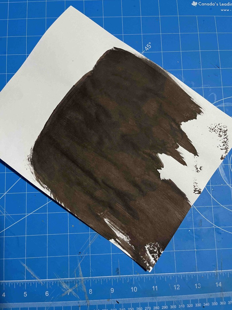
Boom, phase 1: Leathering the jaws I have been away from the pram for a couple of days -- got immersed in some "real" work, only it has been more fun than work. (I'm trying to document all trawl and dredge fishing by Canadians pre-1950, as a very minor contribution to a global effort to figure out how much of the seabed was impacted before modern data collection began. No modelling interest, unless anyone really wants to build a collection of steam and motor trawlers (1890s to 1940s), but it's interesting to trace the evolution of an industry as cold, wet reality smacks up against determined entrepreneurship!) Turning back to the model: It is past time for me to face up to the complexities of the boom. I built the woodwork many days ago, shaping the spar, adding the hook-like cleat to create jaws to fit against the mast and also a (horned) cleat for belaying the clew outhaul. The boom still needs a line for lashing down the tack of the sail, plus a separate one as tack downhaul (for stretching the luff), also the clew outhaul and the upper half of the mainsheet arrangements. But first, those jaws really need some sort of chafing gear, to protect them as the boom moves around while pressed against the mast. The kit leaves the jaws as bare wood, while calling for a piece of copper on the mast to protect that. I figure that both sides of the contact need something and the obvious alternative is copper on the mast and leather on the jaws. (Could just as well be the other way around but coppering a convex surface is a whole lot easier than doing a concave one. So "leather" it will be on the boom. The end effect should look something like: The leather in that image is the dark brown sleeve on the running boom, near the mast. (That's oar leather from Shaw & Tenney, of Maine, as they supply it. So the chocolate-brown colour is the real thing.) The difference with the pram is that an inside curve has to be leathered, rather than wrapping around the boom, so it can't be sewn. Full-size, I might cut the leather so that it had tabs that could be folded outside of the jaws and nailed in place, but that would be tricky at 1:12, so I'm going with gluing the leather in place (literally, on the model, and also as the full-size version that I am trying to represent). {In case anyone is wondering, that's a rarely used boom on a (usually) loose-footed rig and only needed on long down-wind legs under light conditions. So I skipped complexities and it is held to the mast, when needed at all, by a simple snotter: I should have made the snotter longer but then I would need a longer boom and it already takes the full of the length of the cockpit.} Turning back to the pram: I would love for the "leather" to truly be leather but that would be tough to work with at 1:12. (The leather chafing gear on my boat is about 1/8-inch thick, so around 0.25mm at scale. The oar leather might be half that.) Instead, I followed the kit instructions' intentions for leathering oars using paper, though that's on the thin side for the purpose. (My heavy printer paper is about 0.125mm thick. OK for representing oar leather.) The instructions call for the paper to be painted but I thought it would be fun (and just a touch more authentic) to use leather dye. That has the advantage of soaking through the paper, so that cut edges don't stand out white, and it may suffer less from the colour cracking off over time. Anyway, I got to pour dye all over everywhere, spreading it by sponge: After letting it dry, I cut a thin strip, as wide as the jaws, glued it in place with white glue and, once that set, trimmed it by knife. The first time didn't go neatly, so I gave it a second layer and got: I think that went well -- looks as messy as my full-size efforts at doing the same thing. And I still have lots of "leather" left over for the pram's oars. Next up: Sheet blocks Trevor


- 167 replies
-
- 4
-
-
- Norwegian Sailing Pram
- Model Shipways
- (and 1 more)
-
It is not only deckhouses. Hatchway coamings and head-ledges should be upward extensions of the deck's substructure, with the planking added around them later. Yet kits almost never present them that way, nor are model builders warned to make things look like the above-deck structures extend below (even if, in a model, they do not). It's always a bit of a sore point with me: So many beautiful models, made with great skill and endless, patient hours, yet the deckhouses, hatchways etc. look so very unrealistic. Still, I'm sure that Bill is right: Trevor P.S.: While I agree with Wefalck that deckhouses do not sit on the planking, some vessels have had houses of a sort perched on top. I think the big American multi-masted schooners had their galleys in "cabooses" arranged that way, though I may be muddling memories. In a sense, the galley became a sacrificial add-on. Of the vessel was swept by a wave, the structure could go overside, leaving a watertight deck behind. If a proper deckhouse was fitted, it had to be strong enough to never be torn away, lest its removal left a gaping hole. Maybe it also facilitated carrying deck-loads of lumber, as the "caboose" could be lifted up and strapped on top of the load.
-
So sorry to hear that, Mark 🥲 Do what I would never manage and rest your hand until it is fully healed: Resting includes not replying to every message of sympathy! Trevor
-
Thanks JacquesC! I'm learning something of the ways of CA. A tiny drip on the end of a cocktail stick can be transferred to just where it is needed. Then two pieces of (scale) rope can be pressed together between finger and thumb. Timing is critical though: Release fingers too soon and the rope will give way. Hang on too long and you may not get your fingers back! Still, there's something going on with capillary action amongst the fibres, so that two pieces of rope can stick together before either grabs human skin too firmly. (Or maybe I just have naturally greasy, glue-repelling fingers 🙂) With time away from the house today, I've been reconsidering your: I will rig the boom first, so that I can see how badly that is angled upwards. It may be that I have to have that weird forward rake of the mast to avoid the boom drooping. But, just possibly, I could (1) release the present forestay (easily done), (2) rig a temporary and adjustable one from the masthead to a rubber band around the bow, (3) rig an equally temporary shroud on one side, (4) cut away the opposite shroud where it is attached to the mast, (5) glue "splice" an extra length to the cut end, (6) pass that through the eye in the brass mast tang, (7) adjust to a satisfactory length, while fiddling with the temporary shroud and forestay, (8) glue "splice" the new loop through the mast tang, ensuring that I have an acceptable rake and no sideways tilt, while extending the tail of the new line to meet the cut end of the old shroud, (9) "serve" over the combined "splices", (10) repeat steps 4 to 9 with the other shroud, (11) create a new, longer forestay and (12) claim that the long servings on the shrouds are to protect them from wear by the yard 😀 I'm still afraid that I would mess up and make everything worse, but your words are encouraging me to try! Trevor
- 167 replies
-
- 3
-
-
- Norwegian Sailing Pram
- Model Shipways
- (and 1 more)
-
Thank you for your thoughts, gentlemen! At one point, probably after reading your build log, I thought I would get a set of those. Then I thought I was clever enough to manage without. I was wrong and you had a better way. It wasn't a model-driven delay (I had some work to get on with at my keyboard) but I ended up with a 24-hour gap between doing the shrouds and getting serious about the forestay. Plenty of time to decide how to respond to the mistake. It wasn't that I lacked either time or materials for fixing the problem. My concern was how to attach replacement shrouds to the two tiny brass fittings on the mast. Joining shroud to brass then brass to mast had been OK but that was enough experience to make me doubt that I could get new shrouds into place without making everything a whole lot worse. Once I decided to press on, accept the rake and complete the forestay, the model's fate was sealed. I can't raise the enthusiasm to re-do the entire standing rigging. Maybe. With the shrouds held under that rubber band, in lieu of the Quadhands? Thinking about it now, with the experience of completing the forestay while it was in place, on the model, I wonder whether I would not have done better to CA glue the three ends while I had the mast's rake where I wanted it, as in the top image in my previous posting. I have gone years hating and fearing hardware-store CA, which never once worked for me and always created a mess. I am beginning to appreciate the hobby-store high-viscosity version but I am still wary of having drips of it anywhere near the model. So I tried marking the first shroud for length, taking the mast off the model, then gluing the "splice". By the time that I got to the forestay, I was brave enough to take a single drip of CA to the stay where it was on the model, while holding that to the length I wanted. If I had done that with each of the shrouds, then removed the mast and "served" over the glue, maybe all would have gone well. Ah well! This was always intended to be a learning experience and I am learning ... sometimes the hard way 😀 Trevor
- 167 replies
-
- 3
-
-
- Norwegian Sailing Pram
- Model Shipways
- (and 1 more)
-
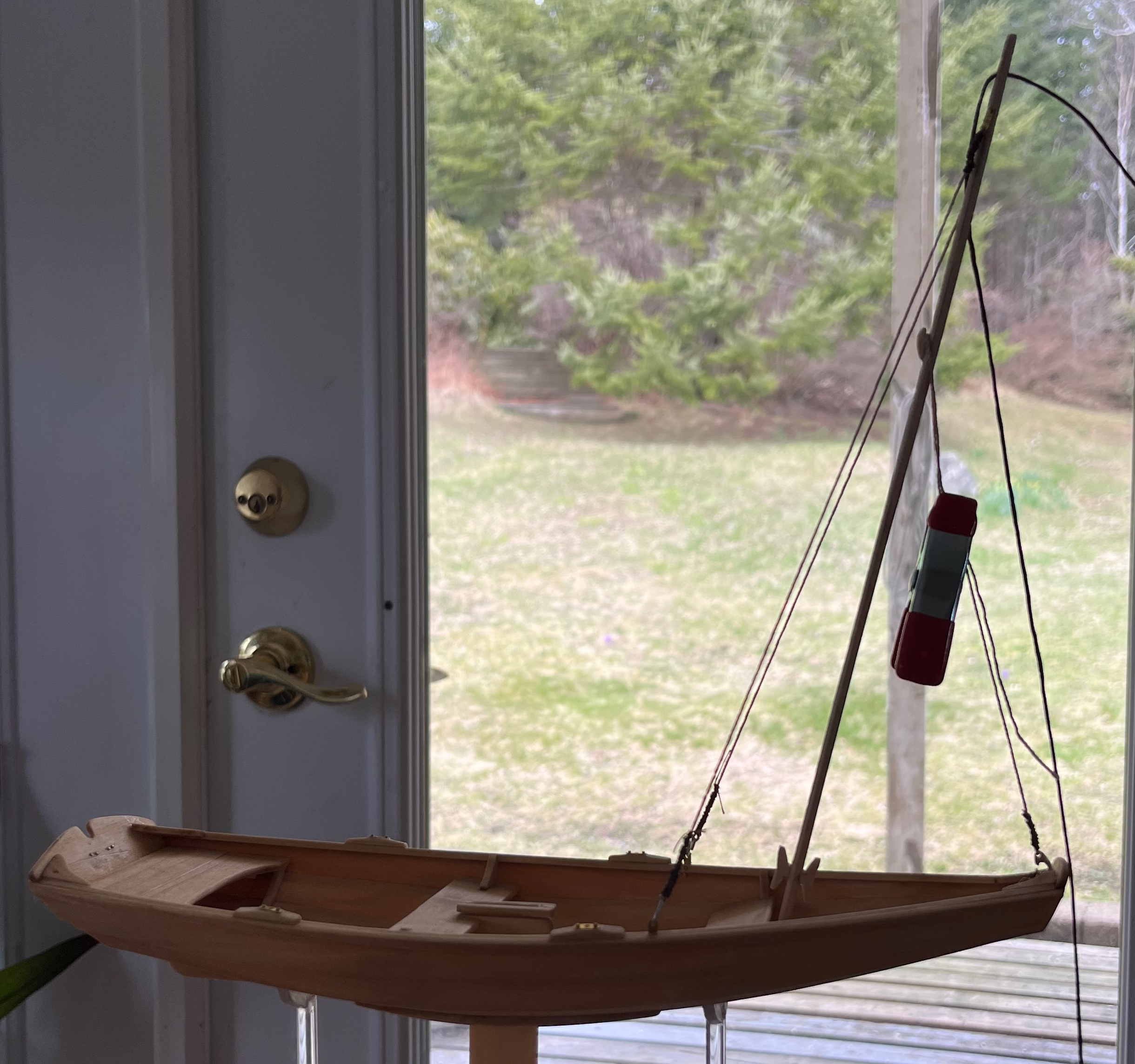
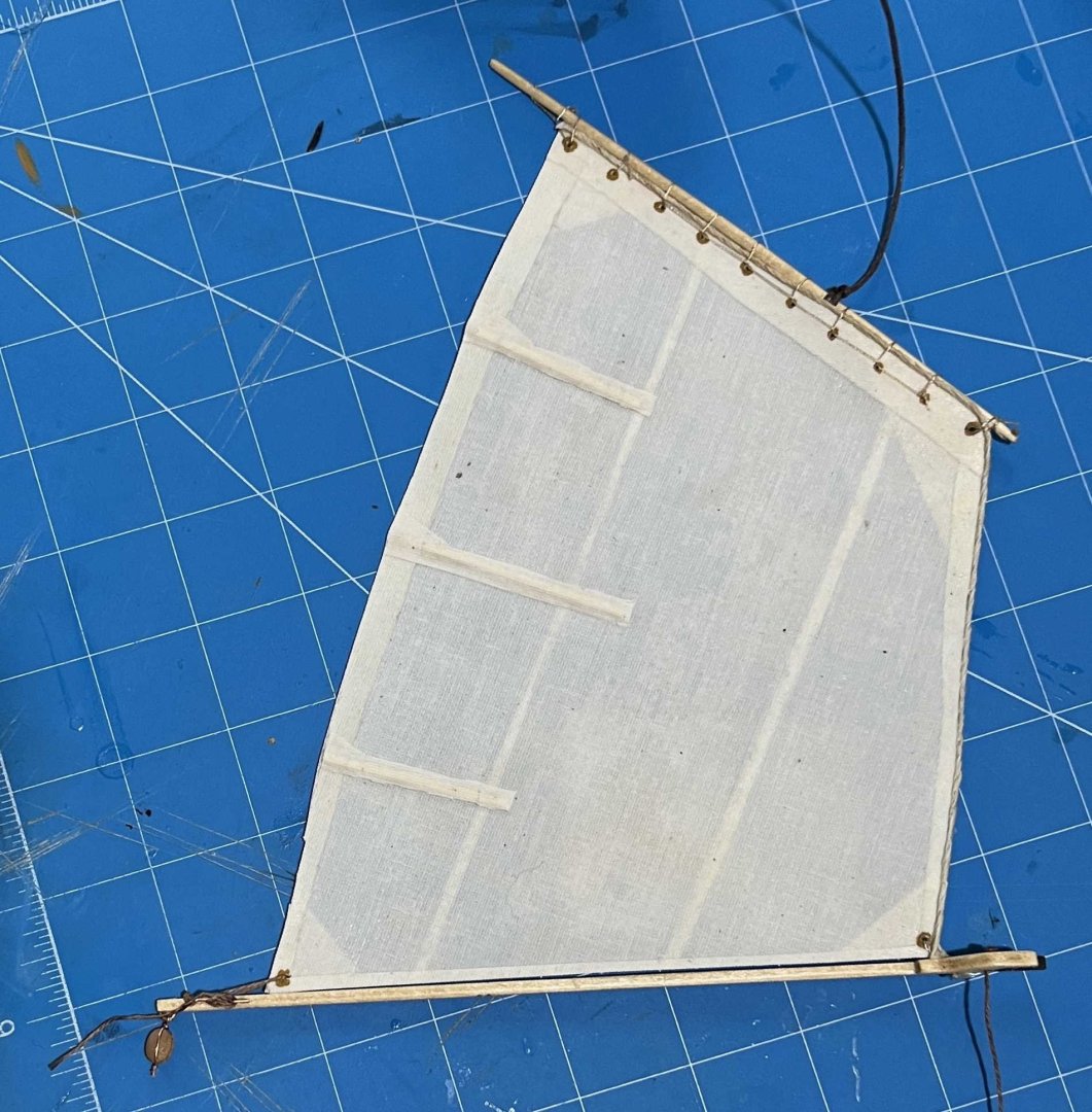
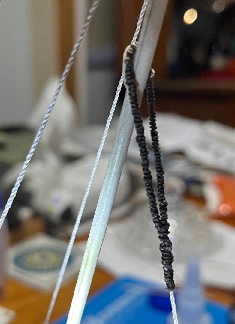
Standing rigging -- FAILURE !!! Since my last progress report, I have finished the pram's standing rigging but the result is far less than "satisfactory". I have got the detailing quite nice but the overall effect is way off. And that's a stupid mistake to make. I thought I had figured out a solution to the challenges but it hasn't worked, so I'll explain what I have done -- not so that others can follow my path but as a warning, in the hope that the next builder of the kit may succeed where I failed. With mast, sail and one end of each piece of standing rigging prepared, the first task was to get the mast temporarily stepped, so that I could measure the required lengths. Playing that game with a 20ft mast of solid pine (!), I attach the shrouds loosely, then get the mast up while maintaining tension on the forestay, finally adjusting and tensioning everything. I figured a similar approach would do. So I caught the ends of the shrouds under a rubber band, stepped the mast and clipped the forestay around the mast and over its cleat. Then clipped the sail more or less in place and adjusted everything until I was happy with the result: The forestay largely sets the rake of the mast (though pulling in opposition to the shrouds) but the shrouds alone determine any tilt to port or starboard. I figured (1) that I could live with more error in the rake than with any tilt, and (2) getting the shrouds both equal to one another and the right length to set tension in the rigging once the forestay was finalized was too much. So the sequence was one shroud to the right length for the desired rake, then the other to exactly match, and only then the forestay made to the length needed for reasonable tension. So I moved one shroud from its rubber band to its chainplate and marked there. So far so good, then the trouble started. The forestay had fed through the hole in its hook without trouble, so I figured the shroud would too. Wrong! In fighting with it, I pulled on the end when only two strands were through the hole, wrecking the line. Smoothed that down but the mark was lost. Got everything together and went back to the model to re-check lengths but with less care than in the above image. "Spliced" and "served" the end of the shroud. Then carefully matched the length of the second shroud and attached that to its hook too. So proudly returned the rig to the model ... only to see: Way too much forward rake! That will completely ruin the appearance of the finished model. Nothing to be done, however. Attempting to cut away that rigging and start over would only make things worse. I still don't know what went wrong. Maybe the shroud slipped slightly before I got it glued. Nor do I know how to avoid the same problem another time, if I did do it over (which I won't). So ... Put that down to a learning experience and persevere with the forestay. With that hooked in place at the bow transom knee and looped around the mast, passing over its cleat. I marked where I wanted the glue "splice" to fall. I went for a very large loop (1) because I could , (2) because I feared that I might have to slip the finished loop up the mast, passing over both (horned) cleats near the foot, but also (3) because I realized that the halliard needs to pass through the forestay loop. The instructions don't have that but it ought to be done on a full-size boat of the pram's design, so on a model too. Most dinghies have forestay and shrouds meeting the mast together, at the "hounds", often with a jib halliard just below. If the mainsail is Bermudan, it will rise higher but its halliard will likely run down inside a hollow mast. Or else the belaying point of the halliard may be offset to one side or the other. The pram has the halliard sheave very near the masthead and the halliard cleat on the centreline of the mast. The yard hangs below the shrouds (and far enough below that it can swing freely from side to side, when the sheet is eased) but the forestay is (oddly) set much lower still, presumably so that the forward end of the yard does not get caught between mast and forestay. Yet that leaves the forestay and the halliard cutting across one another (on the centreline of the mast), leading to friction, wear and failure. Simple solution: Lengthen the forestay loop and reave the halliard through it. With the marks made, I removed the forestay from the model and "served" the whole of the loop -- as I would in full-size to prevent wear of the stay against the mast. Then I re-assembled everything, glued the "splice" with the forestay in place, such that I could control the tension in the rig, and even "served" over that "splice" with the mast stepped and rigged: That much went well, even if the "serving" is too lumpy. However, even perfection in the forestay could not resolve the excess length of the shrouds: It won't look quite as bad once the boom is rigged and the tack of the sail brought abaft the mast. But a huge disappointment all the same 😭 Trevor


- 167 replies
-
- 3
-
-
- Norwegian Sailing Pram
- Model Shipways
- (and 1 more)
-
Coming together really nicely! Trevor
- 55 replies
-
- 1
-
-
- Norwegian Sailing Pram
- Model Shipways
- (and 2 more)
-
Whatever floats your boat! There's plenty of full-size dories on this coast that are not in the traditional colour scheme.
- 71 replies
-
- 1
-
-
- grand banks dory
- midwest products
- (and 2 more)
-
Dories and "dory buff" paint are still very much a living tradition in Nova Scotia. Human memories fade, of course (though not as quickly as the pigments in 1920s marine paints 😀), but I've never heard of anyone doubting that all Lunenburg schooner's dories were buff with green trim. That's just the way to was and still is. Trevor
- 71 replies
-
- 2
-
-
- grand banks dory
- midwest products
- (and 2 more)
-
I will have to go in search of examples!
- 167 replies
-
- 1
-
-
- Norwegian Sailing Pram
- Model Shipways
- (and 1 more)
-
Not as they are when full of wind and pulling. Or has someone been keeping their art hidden from me? 😀
- 167 replies
-
- 1
-
-
- Norwegian Sailing Pram
- Model Shipways
- (and 1 more)
-
Thank you, Mark! A very different technique to your lovely Endeavour sails, with a different final appearance. Now, if only we had a way to make model sails really look like:
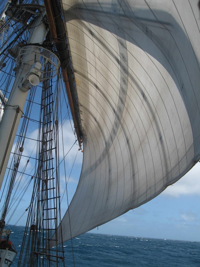
- 167 replies
-
- 2
-
-
- Norwegian Sailing Pram
- Model Shipways
- (and 1 more)