HOLIDAY DONATION DRIVE - SUPPORT MSW - DO YOUR PART TO KEEP THIS GREAT FORUM GOING! (Only 44 donations so far out of 49,000 members - C'mon guys!)
×

Kenchington
-
Posts
679 -
Joined
-
Last visited
Content Type
Profiles
Forums
Gallery
Events
Everything posted by Kenchington
-
 You have studied the primary evidence concerning McKay's ships and, from what I can discern here, you have studied the material closely. I'm interested in the conclusions you have reached but not interested enough to drop other research and delve into the evidence myself. So I can comment (hopefully helpfully!) on what you say but I'm limited and, in the end, can only defer to your judgement. As to why a draughtsman leaves something blank: There are probably too reasons. Either he thinks it very important and does not what to reveal his secrets (and I could point to examples of that) or else the thing left out had no interest for him, at least in the particular drawing (and lots of examples of that too!). The image you posted last evening, labelled "original plans", shows the lines plans. Maybe McKay simply didn't want to engage with purely decorative detail when drawing the lines of his creation. I do agree that any figurehead must be firmly fastened to the hull, or it would swiftly be lost. (Attached to the hull and not, I strongly suspect, to the bowsprit -- though if someone produces evidence to the contrary, I would not be shocked.) 2D imagery can fudge the details of the connection but 3D models should have some realistic structural link. If you find that past models lack that (maybe have only an angel's feet resting on solid timber), then they are clearly deficient. I applaud your efforts to do better! A thought: Some figures, once moved to museums and examined off their ships, prove to be sort of 3-sided, with a deep slot running where a human spine should be. If one of the various pieces that make up the upper stem (the stem itself, gammon knee, cutwater etc.) was extended forwards, it would be possible to insert that piece into the slot in the figure, bolt all together and have the figure well attached without a casual viewer noticing how the attachment was achieved.
 -
I've been bending sail to spars since I was a kid, but I can't answer your question! I don't know whether I would call the lashing "rigging", though I tend to think not. But I have no idea whether that could be considered "correct" or not (in so far as any terminology can really be "correct" or "incorrect"). I think you mean the luff (the leading edge of the sail). That won't be parallel to the mast at all. It is a lug sail, meaning that the yard projects forward of the mast. The upper part of the luff will necessarily be ahead of the mast and the lower part abaft it. Nothing parallel. Trevor
- 55 replies
-
- 2
-

-
- Norwegian Sailing Pram
- Model Shipways
- (and 2 more)
-
I'll offer a couple of wild guesses: Companionways strike me as the kind of thing that would be decorated in whatever way the current captain of a ship wished (and, in Nelson's day, was willing to pay for out of his own pocket). I also suspect that they were the sort of thing that got worn out and replaced by the ship's carpenter at intervals, besides being discarded overboard when going into action or else shattered by shot if kept in place. I'll go beyond guesses and say that it is near-certain that no 1805 companionway survived aboard Victory for modern study, so the examination of deeply-buried paint chips (which has informed understanding of her external colours) hasn't been possible. So ... there may be no good contemporary evidence and no standard to apply. Maybe I'm wrong and someone else can point to something more definite, but I'd say that it's up to the model builder to choose something that looks right. Maybe something that looks like oak that has been both well-oiled and well-rubbed (by seamen's feet!)? There are a lot of contemporary illustrations of life aboard warships of that era, some by professional artists, others by officers sketching for their journals. At least one shows a companionway, so there is some evidence of their shape and form, though the companionway from quarterdeck to wardroom was, very likely, far more elaborate than the ones between the lower and main decks! Trevor
-
There is an old adage to the effect of : "A ship is her own advertisement". Ships move around the seas, visiting the ports where there is trade for their particular kind. They are big, impossible to hide, and draw the eyes of seamen. Thus, there were (and are, for modern vessels) no secrets in the external appearance of a ship -- none that can be kept for long anyway. I have no doubt that McKay developed, then kept to himself, ways to draught the lines of a ship that produced a shape which was efficient as a fast cargo carrier. Many another shipwright has kept the secrets of his craft to himself: Pett famously valued his "models" (likely 2-dimensional ones) above the actual ships that the Dutch burned in the Medway in 1667, to give but one example. Also, long, narrow, wooden ships with sharp ends pose extreme structural challenges, made no easier when internal volume for stowing cargo was a key concern. The solutions to those challenges are not visible externally and McKay may well have kept quiet about the built-up keelsons, diagonal bracing, maybe even hogging trusses, that he used. Amongst other unique ideas, he may well have added additional bracing to the uppermost stem, then hidden that behind a decorated elaboration of the navel hoods. But he would not have had any reason to delete any of his ships' external appearance from illustrations, because all of his competitors were free to examine the real thing to their hearts' content, while standing on a wharf. So, I cannot agree with: Trevor
-
Getting a rudder to work in the broken water flow at a ship's stern was always a major challenge -- hence the fining away of the sections far aft, which then led to problems of hogging, with the weight of the after castle not supported by buoyancy directly below. The leading edge must certainly be as wide as the post, lest little eddies break off the sides of the post and coat the rudder (which would have the same effect as stalling an aircraft's wings). Curiously, there was some opinion in the 18th Century that the trailing edge of the rudder should be thicker than its leading edge -- the opposite of modern notions of hydrodynamic efficiency. They may not have been wrong: At the low speeds normal for sailing vessels, eddies shed off the trailing edge may have created some sort of suction effect, adding to the turning force. Boat rudders were a bit different, as the blade could be proportionate longer (leading to trailing edge). They could have escaped the problem entirely by projecting below the boat's keel, but that doesn't seem to have been normal until the yachting world got involved. Trevor
-
If you are trying to represent the treenails of full-size vessels, those are about an inch or inch-and-a-half in diameter, so a bit less than 1/32 at 1:50. That would be close enough to be going on with though. Trevor
-
Fantastic, JacquesC! I dream of one day finishing the half-hull much as you have. For me, it is only a dream but you have succeeded. Fabulous! Trevor
- 82 replies
-
- 2
-
-

-
- half hull planking project
- half hull
- (and 2 more)
-
I agree and not only for protection from seas: You don't want any of the ship's other gear bashing a boat's rudder, nor the obstruction of the rudder when moving other gear around. Come to that, when putting a boat overboard, using tackles from the mainstay and yard-arm, you don't want anything sticking out and making it even harder to avoid getting hung up on the shrouds, braces and all else. Rudders and tillers neatly shipped, while a boat is aboard, annoy me nearly as much as flags streaming aft while a ship is sailing with her yards squared. Of course, any model is a stylized, simplified representation of full-size reality. Hence any model builder is free to represent that reality as he (or she) pleases. But some things still grate me the wrong way 😖 Brady's "Kedge Anchor" ought to have some comment on how boats were stowed in USN practice, but I can't find much in my reprint. He does say that the bo's'un must inspect the boats on the booms every day after sunset. Also he recommended that, in the tropics, the boats should be uncovered after sunset "in order that they may benefit by the dew and air", the covers being "made up" and placed in the bow of the boat -- all of which strongly suggests that, under other circumstances, the boats were covered, as Dowmer suggested! Trevor
- 54 replies
-
- 2
-
-
- 18 ft cutter
- ships boat
- (and 1 more)
-
Too small for a man to stand up in: Tell him to sit down and stop acting like an idiot!
-
There is a danger to including painted figures in a finished model. Unpainted "ghosts" seem useful for giving a sense of scale, particularly during a build, but a finished, painted figure in the wrong clothes, the wrong posture or engaged in the wrong activity will stand out like a sore thumb -- something like putting a post-1803 white ensign on an 18th Century British warship, an ensign on the jackstaff or the union flag at the mainmast truck. Which means that the model builder doesn't just need to study period ships, their rigging, guns, boats, the handling of their sails etc. etc. but must also engage with costume studies and the social history of the kind of ship presented. To take Nelson's Victory in 1805 as an example: Commissioned officers did not wear boots but buckled shoes, silk stockings and knee breeches. Common seamen were invariably barefoot. Midshipmen and gunroom officers probably followed their betters but most petty officers went barefoot. The officers' uniforms were not very uniform, while the common herd had no uniform at all (aside from the crew of the Admiral's barge or the Captain's gig, who might be dressed up at the expense of the officer in question, if he so chose). And that's the easy stuff, for which historical evidence exists. How would you dress the crew of small trading or fishing vessels of the same era? Or the men aboard an Elizabethan galleon? For those willing to do the research, then develop the skills needed for modelling human figures, there's a huge open field for talent. But it's a big field 😀 Trevor
-
Different prototypes too. The Model Shipways dory is a model of a longer, hence proportionately narrower and shallower, boat. Trevor
- 71 replies
-
- 3
-
-
- grand banks dory
- midwest products
- (and 2 more)
-
I have been following your discussion with interest, though without enough detailed knowledge of McKay's creations to judge amongst the disagreements. However, there is one point at which I fear a misunderstanding has crept in. Maybe it's just terminological confusion but I think those are two entirely unrelated things. "Hood end" usually means the end of a plank that fits into the rabbet on stem or post (or else a similar end elsewhere in a ship's structure, such as on a wing transom). I have no idea of the etymological derivation of that. Maybe from something Dutch?) In contrast, "Navel hood" seems to have originally meant a "hood" (analogous to a head covering) around the hawse holes -- though I do not doubt you are right that McKay extended the decorative elements of the original into a covering for timbers bracing the upper stem -- timbers replacing the old "cheeks of the head", between which the original navel hoods filled a space to prevent the cables from chafing on the angles of the cheeks. "Navel", in that setting, probably meant simply "centre" (from which English separately derives the anatomical navel), as in "between the cheeks". Which brings me to: That is to say that, at the load waterline (hence far below the navel hoods) the horizontal angle of the outer planks, relative to the centreline of the ship, was so narrow that it continued the bevel of the cutwater. It's a bit of a meaningless, almost journalistic, superlative, as the cutwater could readily be given a 45-degree (or even wider) bevel. What is clear is that it has nothing whatever to do with the navel hoods. Likewise for: That describes the bolting of the ends of the planks -- each pair (one starboard, one port) through-bolted with the bolt passing through the stem. Nothing to do with navel hoods. Trevor Related (by marriage) to Nova Scotian McKays -- though from the opposite end of the Province from Donald's birthplace!
-
Yup. Especially if you wrap them around the bit of tube, as the instructions suggest. Trevor
- 55 replies
-
- 1
-
-
- Norwegian Sailing Pram
- Model Shipways
- (and 2 more)
-
It does look a bit lifeless, while the link between blade and shaft looks weak, for something that has to transfer the oarsman's pull. The vase images present some interesting blade shapes, probably stylized but maybe something to work with in developing a shape. Otherwise, oars always look better with the shaft, loom and handle suitably tapered. But that's a lot of work with so many to make! Trevor
-
You're getting ahead of me, Venti! I'm still trying to shape a piece into the tiller I want for my pram. I'm not sure that anyone else has either. I should be ready to try this weekend. If it works, I'll explain my solution in my log. If it doesn't, I'll keep the swearing private! You'll have seen how the kit instructions keep swerving between describing the model and describing the full-size prototype. I'm fairly sure that "bolts" is intended to mean the full-size equivalent of the kit-supplied nails ... except that most of the kits that have reached MSW members seem to have been supplied with a size of nail far too large for the task! Trevor
- 55 replies
-
- 1
-
-
- Norwegian Sailing Pram
- Model Shipways
- (and 2 more)
-
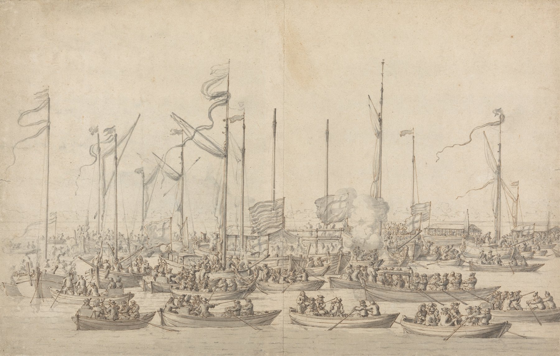
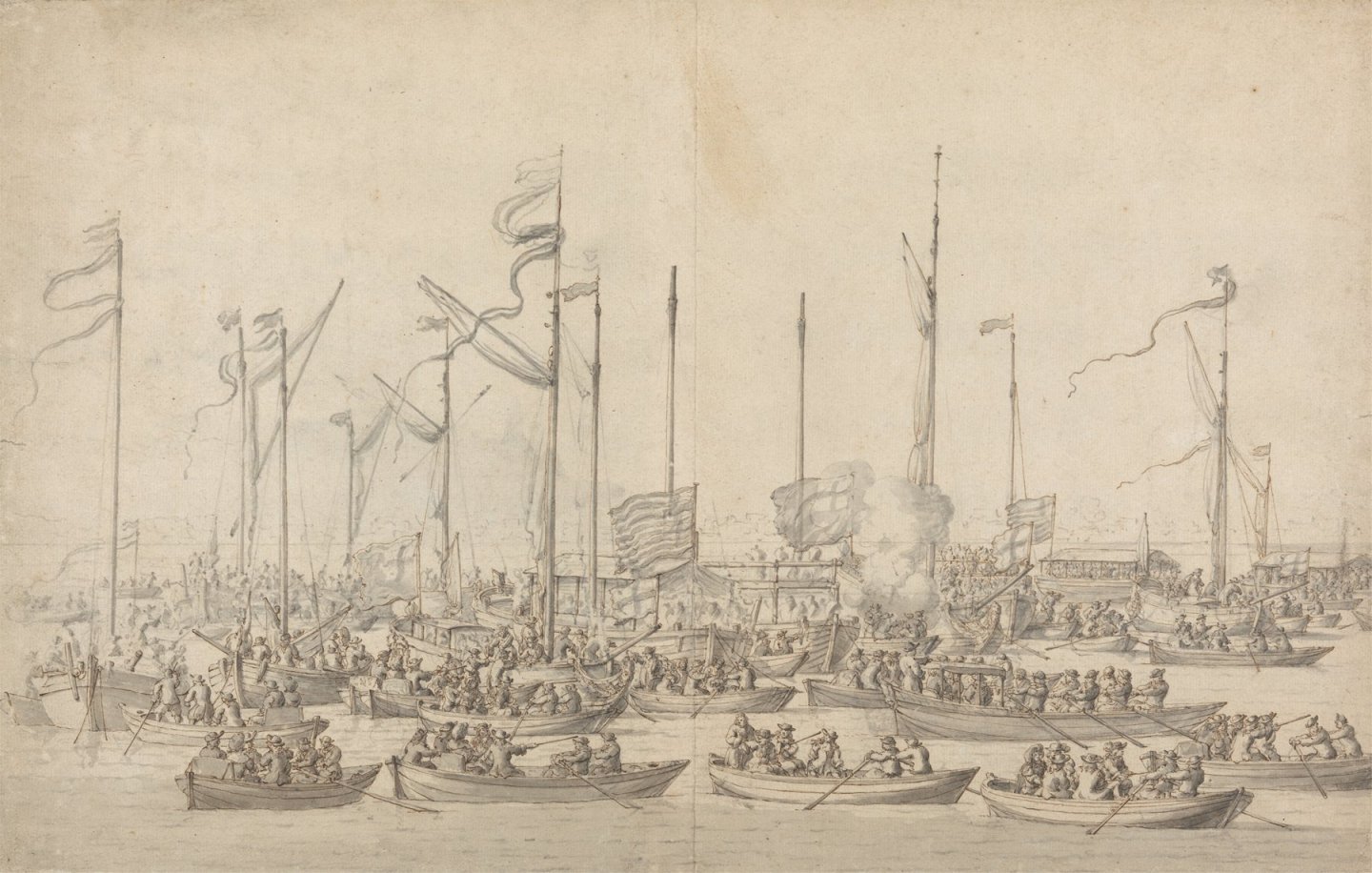
That is Ensor's reconstruction, rather than contemporary evidence. For the latter, you could look at the many drawings by one or other of the van de Veldes, many of which are now available on-line. One example: No notches in gunwales that I can see -- not even on the elite barge (towards the right foreground, with its awning over the passengers). Many of the tholes are, however, of the ornate type that Endsor chose for his reconstruction, rather than simple pins. Maybe that's enough to settle the question for the era of the 1670 Prince but Dan's stated interest is in the War of the Spanish Succession, near half a century later. Whether the notched-gunwale version was in use by then is a whole other question. While I'm writing: Is there evidence that English warships carried their boats on board in the later 17th Century? Earlier on, the boats had often been towed, leaving much more space on deck. Later, boats were certainly carried aboard but on skids or beams above head-height for men working on deck. I haven't gone looking for the practices followed in the 1670s. Trevor
-
Hi Allen, I would be very surprised if there is any contemporary written information on the deck planks of Elizabethan ships. (There was very, very little written about any English ship structures before 1700.) There may be good archaeological data, much of it from study of the Gresham Ship. I ought to get a copy of the report on that work but I don't have access to it so I can't confirm what they may have found. There may be more detail from the Mary Rose, though she was a generation earlier. (I do have 3 volumes of her report but not the one on ship structure! Back in the day, the publisher failed to fulfil my standing order.) For what it's worth, the contemporary Basque whaler excavated at Red Bay, Labrador (for which I have the full report) had deck planking of 25 to 35 cm width and 3 to 4 cm thickness. None survived in its recognizable position from the upper decks but dimensions could be deduced from fastening holes in the beams and the thickness of other pieces that the planking butted up against. At 1:60, 0.5mm thickness and 5mm width would be about right for the decks visible in a model. The outer planking of that ship was white oak, as were the structural parts, but wood fragments interpreted as remnants of planking from the upper decks included pine and larch. I don't think that the archaeologists' report drew the conclusion but I'll guess that the upper-deck planking had not survived because it was (less durable) softwood. If so, the colour should be about the same as in the holystoned pine deck of a 19th Century Yankee clipper. That being said, please take note of the variable plank widths on the whaler. Whatever else, she did not have evenly laid, parallel-sided deck planking. I'll add another guess based on other evidence from her time: Much of the visible "deck" probably wasn't planked at all but was one long opening, mostly covered by gratings, running down the centreline, with planking only on what we might call "side-decks". In short, reproducing the appearance of the real Golden Hind, as seen from above, would need a lot of study followed by some sweeping assumptions. If you're not looking at going that far, then there may not be much point in worrying excessively about plank widths and colours. Trevor
-
I love the way the thwarts and floorboards stand out against the red paint! I understand, but you did make a better job of those boards than I did. It is a much, much trickier step than it looks at first. Trevor
- 55 replies
-
- 1
-
-
- Norwegian Sailing Pram
- Model Shipways
- (and 2 more)
-
Why, than you, Alan! I am glad you are enjoying it! Trevor
- 167 replies
-
- 1
-
-
- Norwegian Sailing Pram
- Model Shipways
- (and 1 more)
-
Not necessarily "faux". English vessels of the size of Ranger but built a few decades later had stanchions separate from the top timbers of the frames -- in contrast to contemporary big-ship practice. I have never heard why. (There were cases of rails torn off by boarding seas, leaving a line of holes where the stanchions had been. Not a good thing to have happen.) Those kit pieces represent the stanchions and I'll guess that they are as accurate (in spacing and scantlings) as Chris W. could reconstruct from the available surviving information. Trevor
- 133 replies
-
- 4
-
-
- Ranger
- vanguard models
- (and 1 more)
-
Noooooo!!!!!!!!! Model Expo's Norwegian pram is quite enough, thanks 😀
-
And "xx" could mean more than one (entirely different) boat or ship type, at the same time and different places or different times at the same place. (Anyone wan to try a universal definition of "frigate"???) Meanwhile, type "AA" could be called "xx" at one time and place but "yy" somewhere (or somewhen) different or if the same hull was put to a different use, even if given a different rig. Ain't technical terminology fun? And no two ships were ever built exactly the same way, even when the same crew of shipwrights worked on both. I've sometimes wondered whether we couldn't identify both the yard which built a wrecked ship and the date of her building by examining details of surviving wreckage, and do so with at least as reliable results as the fine-art people get when determining which great master did a particular portrait, if only we had reference collections for each yard. Boats are more likely to be mass produced, as with banks dories from the larger builders. But they can vary too: These's an interesting paper in "Mariner's Mirror", from a good few years back now, describing how a boatbuilder in one English town (on the River Dart, IIRC) would get on his push-bike and cycle to a nearby fishing village, where he and his client would look at the boats on the beach. The client would say something to the effect of: "Like that one, but a foot longer, and with a wider stern, like the one over there". Then the boatbuilder would keep that in his head, cycle back to his home and, a few weeks later, a carter would deliver the completed boat, looking a lot like all the others on the beach but subtly different from each of them. Before Nova Scotian lobster boats were popped out of plastic moulds, you could see the effects of a similar process at work: Most boats in one harbour would have a lot in common, but subtle differences from one another, while those in the next harbour (where the fishermen patronized a different builder) would again have a lot in common with one another but more detail differences from the boats in the first harbour. Then again, there's a neat study of one community in Newfoundland (Winterton, on Trinity Bay), where the most skilled boatbuilder was himself a fisherman. Each winter, he would build himself a new boat, which he would sell to one of his neighbours the next year, as he worked step by step towards his own notion of a perfect boat for the local fishery. In all that, when we say something like "yawl" or "battleship", we impose a rigid terminology on the continuously varying products of technological evolution and it just doesn't work well. (Doesn't work as well a most people suppose when we do the same with the outputs of biological evolution either, but that's not a topic for MSW!) Trevor
- 54 replies
-
- 1
-
-
- 18 ft cutter
- ships boat
- (and 1 more)