
HOLIDAY DONATION DRIVE - SUPPORT MSW - DO YOUR PART TO KEEP THIS GREAT FORUM GOING! (Only 44 donations so far out of 49,000 members - C'mon guys!)
×

Kenchington
-
Posts
679 -
Joined
-
Last visited
Content Type
Profiles
Forums
Gallery
Events
Everything posted by Kenchington
-
 The first and most essential routine daily-maintenance task on a sailing ship was (and is) to polish the brass of the binnacle. If you want realism, it should shine like gold! An example on a Cutty Sark -lookalike: Trevor
-
Nice! A (very) distant cousin of mine (our last common paternal ancestor born around 1678) was a shipwright at the Hard in the years around 1800, before moving to Parsons new yard in Warsash by 1810. No record tells of who worked on which ship but William K. may have had some hand in building the frigate Euryalus and the 74 Swiftsure, as they were built at the Hard during the years that his children were baptized there. Sadly, I never got to visit the place before leaving England. Trevor
-
Jared, Very sorry to hear of your struggles! You seem to be facing them bravely and successfully. You asked: When in (or entering or leaving) port is when a clipper would be shown off with flags. When out at sea, there was no point in wearing out expensive bunting by having it flapping in the gales with nobody to see it, except for some kind of masthead pennant to indicate wind direction to those on board. The ensign and perhaps the ship's "number" would be shown when passing close enough to another ship for those flags to be recognized. If there was some special message to be sent, code flags could be shown. But that was about it. You also suggested: If you do that, you'll need to be sure that that the internal structure is either reasonably realistic or perhaps stylized (as the original Navy Board models were). I don't know the Model Shipways Essex kit but kits with that rise to those standards are few and far between. Trevor
- 431 replies
-
- 1
-

-
- Flying Fish
- Model Shipways
- (and 2 more)
-
Joking aside, she was throwing up a mighty bow wave in your photos. The wavelength varied a bit from image to image but roughly three wavelengths in the LOA, so a wavelength of about 165 ft at full size. I make that a wave speed (and hence the speed of the hull) of about 17 or 18 knots -- which is what Puncher and her sisters were designed to do. So the wave-making may have been quite realistic. Looks like they were very wet forward, if driven hard into a head sea! Wave speeds don't scale linearly, of course. If your model really was generating a bow wave of 165/144 =1.146 ft wavelength (as per my estimate), then she was moving at around 1.5 knots -- nice and slow. But at 1:144, that scales to 213 knots full-size equivalent! You hardly need an air wing on board if you can drive her that fast. One caution, though: I have used the formula for deep-water waves. That's probably right for your pond, as the waves were quite small (if measured without considering the model scale), but if the pond is really shallow the wavelength-to-speed relation would depend on water depth. Trevor
- 51 replies
-
- 2
-

-
- Puncher
- escort carrier
- (and 1 more)
-
Before all is done, I hope you are going to show us flight-ops, with aircraft taking off and landing on as she steams around the pond 😄 Trevor
- 51 replies
-
- 2
-

-
- Puncher
- escort carrier
- (and 1 more)
-
Top image is the Blue Peter at the foremast head -- traditional signal that a ship was ready to sail. (The same flag is now P, or "Papa" in the NATO phonetic alphabet, with much the same meaning.) The bottom image probably began as an attempt to show the ship's own identification "Number" (actually a group of four letters -- nowadays far more often used as radio call sign), plus her ensign. As it has fallen from the rigging, the group of flags has become inverted. The bottom (originally top) is the (British) Red Ensign, with most of its length broken away but the Union still visible in the upper canton. Next is code flag H. The blue saltire on a white field is not a flag of the modern International Code but that has changed a bit over the decades, so I'll not say it was wrong for the era represented. There were probably two other flags (now lost) to complete the "Number". The middle image is the owners House Flag. Someone may know whether any real-world owner used that design, though it could have been the model-builder's imagination (probably with L for "Line"). Alternatively, I wonder whether the builder "signed" his model by putting his initials there. He may have been A.L. Trevor
-
I'd say the intent was to model a ship from long after the HEIC lost its monopoly on shipping to the East: As Chris noted, the chainplates are inboard, so later 19th-Century. Then again, she is very bluff in the bow at deck level (though sharp below the waterline), which looks more like the pre-clipper generation of (relatively) fast ships -- "square as a brick, fore and aft" as was said of them at the time. Yet the model has some features reminiscent of Cutty Sark, so I'll guess that the builder was inspired by the last of the tea clippers but didn't get the proportions right. Curiously, while there have been ships called "Bombay Star" in the past half-century, Google doesn't find me any record of a sailing ship of that name. So the model is someone's attempt to represent a generic sailing ship of the (very roughly) 1860--1880 period. I did wonder whether it might have been a sailor-made model. Those tended towards very realistic details but poor overall proportions. However, your model misses too much of the realism (note the fore topsail sheet bits placed on the forecastle head, rather than at the foot of the mast, and the hood over the forecastle companionway that would obstruct use of the capstan ahead of it). So I would guess a model by an on-shore enthusiast. Could have been made at any time in the past 150 years. But perhaps you can make out something on the house flag (near the top of the mainmast)? I think I can see an A and an L but anything else is lost in your photos. Trevor
-
Welcome ... from the other end of Nova Scotia! Trevor
-
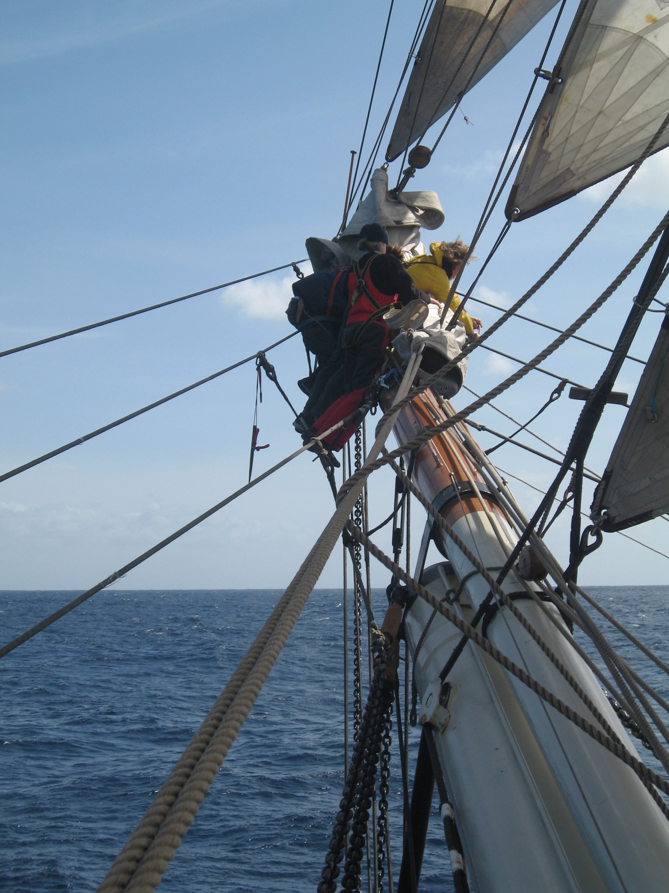
I think I'm with @Alvb on this. Sure, if a fit, young seaman can get from the topgallant yard to the deck by sliding down a backstay (and that was done, at least in the last decades of the big windjammers), then he can take a run at the forecastle and try to get up a sloping surface of planking (even though lapstrake could hardly be better designed to deny finger and toe holds!). But that just doesn't seem to be a practical route for everyday use. Also: You don't need any space for vertical access between decks. All you need is some steps, either cut into the corners of a vertical structural timber or else nailed onto its sides. Anything will do: The foremast itself, the knighthead for the foreyard tye or anything else, so long as it spans from one deck to the next above. And you need a scuttle in the deck above, of course, for a man to emerge through. That sort of crude ladder was normal for getting into and out of the holds of later sailing warships, even when (quicker and more convenient) stair-like companionways were fitted in high-traffic areas. Trevor
-
"Lifelines", yes (though that term also has other meanings). Their primary purpose is for men in the water to hang onto or (better) get between boat and line, with arms over the line so they could hang there securely. I'm not certain when they were introduced and not even sure whether any firm evidence exists. At least some rescue-lifeboats (the ones that put out from shore after an accident has occurred) had them by the mid-19th Century and some boats on passenger steamers by the early 20th -- both confirmed by photographic evidence. Not so sure that the boats carried by deep-water sailing cargo-carriers ever did, even in the 1930s. Trevor
-
A week ago, I would have agreed absolutely and firmly declared that there could be no other way. However, after having all four volumes taking up shelf space for more than 20 years, I am finally working through Jean Boudriot's remarkable "74-Gun Ship" (the English edition). In Volume 3, he presents French practice of circa 1780 as spreading the head of each stuns'l to blocks on the boom on the yard above, as its foot was spread to the boom below. Boudriot did not footnote every little detail and a few of his claims are surprising, so I'll not swear that he must have been right. Besides, what was done in France in 1780 may never have been done in the US during the War of 1812. (Why drag around the extra windage of stuns'l gear on the t'gans'l yard when the stuns'l is very rarely set and the alternative of hoisting a short yard for the head is being used successfully by your neighbours?) So if it was my model, I would follow @Dr PR . I just wouldn't be as dogmatic about it as I used to be! Trevor
-
Lovely gratings along the centreline of the deck! Too few models show those. Trevor
-
Not just "fairly convincing". For the scale of the kit, your work is incredible! Trevor
- 321 replies
-
- 4
-
-
-
- Sovereign of the Seas
- Airfix
- (and 1 more)
-
I would try middling the line (that is to become the block's strop) around something like a thick needle, then catch the two ends together with a series of half-hitches in fine thread (representing a seizing). Add a dab of glue if necessary, then slide out the needle. That leaves your becket. Place the block into the crotch between the two ends of the strop and either tie those with a half knot (half a reef knot) held with a dab of glue or else apply another "seizing". Then lead the free ends through the eye of the bolt and tie in place, trim the ends and hide them under more "seizing" if you choose. That way, all the fiddly stuff is done away from the rest of the model, while all the mess is hidden between block and eyebolt, where the full-size vessel will have had sister-hooks or shackles or some such -- all of it too complicated to replicate at 1:64 but giving every excuse to represent with an excess if thread. Trevor
- 133 replies
-
- 3
-
-
- Ranger
- vanguard models
- (and 1 more)
-
Yes. Maybe not always in a small boat but, in a vessel of Ranger's size, definitely yes. Trevor
- 133 replies
-
- 3
-
-
- Ranger
- vanguard models
- (and 1 more)
-
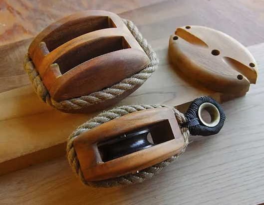
The "loop" is a "becket" and the block would be known as a "single block with becket". In the case of Ranger, the blocks are rope-stropped (rather than built around a metal structure), so the becket (by which the standing end of the tackle is attached) and the eye (by which the block is fastened to the bowsprit) are both made from a single loop of rope. In full-size, that should be a grommet, made by laying up a single strand to make a loop, but at scale you will, of course, tie it off as you would any other block. Full-size, both the becket and the eye would have thimbles in them to prevent chafe of the grommet. Whether you want to go that far at scale is up to you! Trevor
- 133 replies
-
- 3
-
-
- Ranger
- vanguard models
- (and 1 more)
-
Black because strops for blocks will often (not always) be served with tarred marline to protect from both weather and chafe. But use whatever thickness fills the score around the block without overfilling it. Bigger blocks will need thicker line and vice versa. One example of how it ought to look (though without serving on the strops): Trevor
- 133 replies
-
- 3
-
-
- Ranger
- vanguard models
- (and 1 more)
-
Diameter of shrouds Heller 1/100 HMS Victory
Kenchington replied to JEFFRAV's topic in Masting, rigging and sails
If it's any reassurance, my calculator says that 11-inch circumference (full scale) is just short of 0.89 mm diameter at 1:100. So, yes, 0.9 mm is right. Unless we are both making the same mistake 🙂 Trevor -
If it was me, I'd decline to get mixed up in the paperwork. Who can know, from day to day, what might be required at the border? For a small company, the hassles simply would not be worthwhile, when we in Canada only comprise a tenth of the North American market. (A tenth of the population. I don't know whether ship-modelling is more or less prevalent north of the border.) Sure it's limiting for us and, when (if?) some stability returns to trade arrangements, Model Expo will find that they have lost some market-share. But, in the interim, I'd not fault their decision. Maybe the medium-term answer would be for a Canadian company to import for re-sale, making each delivery large enough to justify the complications. But who, this side of the border, would be willing to take on the risk of purchasing multiple kits, when direct supply from Florida could re-start at any time? Trevor
-
There's another layer of complication here. Many people suppose that, if they own an original artwork, they also own the copyright. While laws vary from one jurisdiction to another, generally that is false and everything is copyright-free once beyond some set age (25, 50 or 75 years, perhaps) or if the creator of the original died more than some number of years ago. However, large organizations that hold original artworks, such as art galleries and museums, look to cover their expenses through fees for re-use of their images. They get around the problem by making images available for publication subject to limitations to specified uses and contractual terms that forbid other uses that have not been paid for. Thus, somebody might find a published reproduction of an 18th-Century painting (hence long out of copyright) but it would not necessarily be legal to scan that image and re-publish it, outside of the "fair use" limits. Then again, if the museum took its image-reproduction fee and failed to ensure that the licensed user included the appropriate wording in the published image caption, the image may have entered the pubic domain -- with the museum left to sue the licensed user for failure to follow its contractual obligations. Commercial publishers presumably employ lawyers who understand this stuff and keep them on the legal side of the limits. Then again, they make enough money from book sales to pay those lawyers. People posting things on Pinterest most likely ignore the rules, while the image-owners ignore the violations. MSW falls somewhere between the two and I can see why our moderators are concerned. Trevor
-
Photographs of Bluenose in her racing days show her cap rails as pale from bow to stern. The images were in black & white, of course, so I cannot say whether the rails were actually white, though that is very likely. In the same images, her bowsprit appears in a medium grey, so definitely not painted white. Most likely, it was finished as oiled wood -- hence a light brown stain in a model. Trevor
- 44 replies
-
- 4
-
-
- Scientific
- Billings Boats
- (and 1 more)
-
Only one-third as long as my pram has sat waiting to be finished! Hope to be back at that before too much longer.
-
Try Rodger's "The Wooden World" for an authoritative explanation. He is explicit that his book deals with the RN of the mid-18th Century, and the social structure of the navy had certainly changed by the time of the Revolutionary and Napoleonic wars, but the seniority of captains and admirals had not. Another complication, which may account for your cases of individuals "skipping colours", was that the number of admirals in each rank and colour increased over time. In the 17th Century, with three colours and three ranks (full, vice and rear), there were only nine admirals in all. By the mid-18th, there were 30: one Admiral of the Fleet, six Admirals (three each White and Blue), eight Vice (not sure why that wasn't nine!) and 15 Rear (five of each colour). By the end of the long wars, in 1815, there were, by one claim, 219! With everyone stepping up according to seniority, each expansion of the total number will have meant a lot of officers skipping steps in the hierarchy. I can't immediately find any source that says when the RN changed to merit-based promotion of Rear, Vice and full Admirals. The final advance to Admiral of the Fleet (which very few achieved, of course) was mostly by seniority as late as 1914, though there were individual cases of exceptions from the 1890s. Trevor
-
Not so in the Royal Navy through to Nelson's time and beyond. The last promotion any commissioned sea officer could have was to Post Captain. Thereafter, everyone moved up by strict seniority, based on the date of being Made Post. Hence, a Rear Admiral of the Red was always senior to a Rear Admiral of the Blue because the former had been Made Post earlier. Likewise, any Vice Admiral was senior to any Rear Admiral, by date of being Made Post, besides the difference in their ranks. Commodore was certainly a temporary appointment but it did not give the individual authority over more senior officers. Instead, Admiralty had to go to some trouble to ensure that all other officers in a fleet or squadron were junior (in the date of their having been Made Post) to the chosen commander. If the latter had already achieved his flag, he served as Admiral. If insufficient vacancies had emerged at the top, the Captain chosen to command was appointed Commodore. It was a cumbersome system, that only worked because pragmatic adjustments were made to get around a rigid tradition. But it did work, more often than not! Trevor
-
Some are models of Bluenose II and, though she was launched before the Maple Leaf became Canada's flag, most of her long career has been after the adoption of that one. As for those kits which place the Maple Leaf on a Bluenose with fishing gear aboard: I'd just blame the arrogance and ignorance of kit manufacturers who can't be bothered to get the details right. I wonder how many kits of USN sailing warships (aside from Constitution, when portrayed as a museum ship) come with 50-star jacks and ensigns? How many representations of 18th-Century RN ships have post-1803 jacks and ensigns? How many have white ensigns when on a station where the C-in-C was a Red or Blue Admiral or when in independent service? There's more than enough kits sold with instructions calling for a jack at the main truck or the ensign staff! Sad. Trevor
