HOLIDAY DONATION DRIVE - SUPPORT MSW - DO YOUR PART TO KEEP THIS GREAT FORUM GOING! (Only 36 donations so far out of 49,000 members - C'mon guys!)
×

Kenchington
-
Posts
679 -
Joined
-
Last visited
Content Type
Profiles
Forums
Gallery
Events
Everything posted by Kenchington
-
 When I first came to Nova Scotia, near a half-century ago, there was an old joke still getting passed around. It was said that, if a bluenose (a Nova Scotian) was ever to rig a bathtub, he'd make it a schooner. Mainers weren't (and aren't) so very different from us. Back in 1994, I got to watch the local boats return to a harbour in El Salvador, after a day of fishing. The smallest of them all, hardly more than a canoe, had her name in large letters down her side: "Bismarck". Some humour is timeless! Trevor
 -
One thing to understand is that, although the men in corporate boardrooms of ship-owning companies may only care about utility, those who work on the water are motivated by the same suite of urges that drive the yachting fraternity-- even though most would hate to admit it. Of course, it is essential on the commercial side to bring in more than the outgoings (whereas the reverse is true of the recreational side) but there's the same pride in the boat, the same wish to display the superiority of the boat to outside observers, the same desire for comfort in so far as that can be afforded and so on. Hence, I suspect that the prominent gammon knee that forms the "clipper" stem profile of a Friendship sloop was always primarily decorative. That aside, the forward rake of the Friendship's stem (in contrast to the plum stem of smaller boats on Muscongus Bay) went with a lot of flare well forward. That will have helped the bow rise to waves, hence suiting a sloop to winter lobstering, in worse weather and further from shore than the summer fishery. (There are boat types that have the flare without the rake but it's not an easy shape to plank.) However, there's fashion and appearance there too. A man who could only afford a sloop for lobstering still wanted a boat that looked like the great Gloucester schooners -- much as a man who drives a Ford would prefer one that looks like a BMW or a Jaguar. That's the way we human males are 😎 The choice between lapstrake and carvel is a whole lot murkier. All else being equal, lapstrake is probably lighter, so easier to haul ashore in places where that is advantageous. However, fitting watertight bulkheads is much easier in a carvel hull, while the strength of a lapstrake hull is more badly affected by cutting holes in the planks. So a desire to have a live well would encourage the choice of carvel. But my guess is that there were two alternatives, each complete to itself. They needed different types and sizes of lumber, with different costs, different skills in the boatyard, different labour demands (lots of hours needed to clench all the nails in a big lapstrake hull), different maintenance (no need for a man to re-caulk his lapstrake boat) and so on. The optimum balance amongst all those encouraged carvel for larger hulls, lapstrake for smaller, with the critical size decreasing through time -- partly as relative costs changed, partly as fashions and expectations shifted. The Muscongus Bay sloops of the later 19th Century seem to have lain near the break-point for their time and place, so that personal preference could push the choice one way or the other. If that's complicated, what do we make of the boat types that had part-lapstrake, part-carvel construction? The English even had some early steam tugs with that duality. Weird! Trevor
-
OK: I stand corrected! Not what I would have expected, but I clearly need to re-read Chapelle before posting. Was it he or one of the US Fish Commission authors who said something about the cuddy being heated in winter -- not for the comfort of the fishermen but to keep the lobsters from freezing? I'd not want to share my living space with the catch but if that was the only way to earn a living in the fishery, men had to do what they had to do. Trevor
-
I have been mulling over this point through recent days. The real world is variable, with layers upon layers of variations. But the human brain does love to group and classify. Indeed, academic disciplines need classifications to get order out of a chaos of data and find the underlying truths. So we have Linneaus' system for classifying plants and animals, Lyell's arrangements for sorting the ages of rocks and so forth. Historians of ships and boats have to do the same. Sometimes, there is real order -- as in a frigate built to the standard design for a certain class. Friendship sloops weren't as uniform as that but they could be recognized and, to some extent, distinguished from the other sloop designs used elsewhere along the New England coasts. However, other times, the chaos overwhelms the order and academics end up imposing a terminological order on a chaotic reality. It rather looks like the Muscongus Bay centreboarders were a case in point. Chapelle wasn't wrong to group them together and stick a label on them but they weren't uniform. There's lots of interesting questions here: Why do recognizable "types" of boats often arise? And why do they sometimes not? As technological evolution can be so rapid, how should we classify the products of an on-going evolutionary development? When does one "type" become another? (Palaeontologists have the same problem, if the fossil record is rich, and have to invoke "chronospecies", distinguished from one another by breaks at largely-arbitrary points in time.) Then there's what labels we apply to whatever groups we recognize. Nautical historians have tended to use contemporary terminology, which isn't always helpful. There have been many utterly different types of vessel, through some four centuries, all labelled "frigate" -- which doesn't aid clarity. "Battlecruiser" didn't get used for so long but was applied to multiple, very different types within a half-century or so. Then we could spend hours listing the various meanings of "sloop" and "smack". It ain't simple! Trevor
-
I would doubt that, on a New England fishing boat. "Stern sheets" is terminology for the kinds of boats used to transport officers or other up-market passengers. But I'd not call any of the seats "benches". That's landsman's terminology. For myself, I'd call them all "cockpit seats", though that may be just me carrying over a yachtsman's term. If there's a "cabinet" aboard, it would be in the cuddy. In the cockpit, you're talking "lockers" or specifically "cockpit lockers", with the locker lids serving as cockpit seats. On my own boat, the lockers right aft are the "lazarette" but, once again, that's not terminology I would expect to be understood on a New England fishing boat. I'd certainly expect that the frames would be visible. That is, I would not expect such a boat to have any ceiling. Doesn't Chapelle say something about the earlier Muscongus Bay boats being open, even though we choose to model later ones with cockpit soles rather than light floorboards? Trevor
-
Good to hear that, @SaltyScot! I'm in the same status as you: Alive, kicking but not building models. Amongst other tasks, I'm touching up the paint on the house. But when I went to scrape the living-room window, the paint came off and revealed ... nothing. Nothing but a big hole, where ants had eaten everything away. So now I have to get a new window installed, complete with rebuilding the house structure around it. What a joy! Trevor
-
Nothing bigger than a basket of fish to pass down or up through that hatchway but lots of water on deck to keep out of the fish hold! Trevor
-
Thank you for doing this translation and presentation, @Waldemar! You have taken on a major effort but it will be very, very valuable -- to me, at least. Trevor
-
I would say, in general, no. They were usually permanently fastened in place and anyway were thought to be essential to the function of the vessel. That seems odd to a modern mind but our notions of cause-and-effect date from the Enlightenment. It took a long while for practical seamen, shipwrights and so forth to see that light, so well into the 18th Century men supposed that the carvings were as vital to the power of a warship as her guns were. (Considering that scaring the other guy into submission was half the point, the idea wasn't entirely wrong anyway.) For Nonsuch, fighting wasn't the objective but the grandeur of the Company was. The carvings were a projection of that. Trevor
-
What If Lusitania Hit the Titanic’s Iceberg?
Kenchington replied to uss frolick's topic in Nautical/Naval History
Interesting that the Cunarders had less internal subdivision than the White Star ships. That would indeed have made them more vulnerable, though there is also a question of low-temperature brittleness of Titanic's plating, which may not have been true of Lusitania's. The big unknown will always be the human element: The liner companies were tied into free advertising, through media interest in the big ships, which sometimes focused on irrelevancies. (How many railway tracks could be laid, side-by-side, through each ship's funnels was an especially bizarre one.) Thus, Titanic's officers were under some extra pressure to set a fast time to New York on her maiden voyage, which the newspapers would cover. Lusitania could have afforded to slow down while passing the ice field. Whether she would have done, when Cunard competed on speed (versus White Star's luxury), is unknowable. -
Footropes, Flemish Horses and Stirrups
Kenchington replied to hof00's topic in Masting, rigging and sails
Just for fun, here's the gear in use: Note the reef tackle (beneath the feet of the men on the yard) hauled from the deck and easing the strain on those aloft. The stuns'l boom has been topped up to give some clearance but the skilled man, at the yardarm, has it under his arm. His feet are braced on the Flemish horse as he hauls (though the earring is not shown accurately). The other men are supposed to take hold of reef points and pull to windward to ease the load on the man passing the weather earring. Later, they will let the wind do the work of stretching the sail toward the lee earring, before gathering up the canvas and tying the reef points. I have only participated in this task the once and that only in a training exercise, not when a reef needed to be tucked in. (In the old insult of greenhorns, I was strictly a "bunt reefer and yardarm furler", the skilled work being needed in furling the bunt but passing the earring when reefing!) If anyone cares, that was on the topsail yard of Rose, during a sail from Halifax to Lunenburg before she went off to Hollywood to play at being Surprise. Trevor_RMG_PW3760.jpg.3ee39efa1e2e5a5a417c2007d1fc2769.jpg)
-
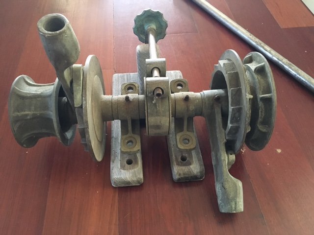
I went looking for images of windlasses similar to my previous guess and found a couple that had been sold in recent years but were still posted on he sale websites -- both once-lovely bronze yacht fittings, as those are the ones that have survived:
-
My best guess is that the two projections pointing aft (in profile: level with the axis of the windlass; in plan: aligned with toothed gears immediately inboard of the warping drums) ended in sockets into which the crew could insert wooden levers (modern versions of the old handspikes). Then it would be a matter of lifting the lever as pawls (built into those same projecting parts) rattled across the teeth of the gear, before pulling aft and down to turn the drums. With two men working the levers out of sync with each other, a fairly steady pull could have been maintained. That would suffice for a small vessel, particularly one not operated much in heavy weather and never needing to anchor in deep water. John Harland's 2015 paper on capstans and windlasses (in Mariner's Mirror vol. 101, pp. 38-62) has an illustration of something of the sort as its Fig 26, taken from a patent filed by Charles Perley of New York (date not stated but probably 1850s to mid-1860s, as that was when Perley filed other windlass patents). Trevor
-
My trouble is that the type of windlass isn't obvious from the drawing -- probably because (as the recorder noted) "Windlass removed by present owner". Before removal, it's just possible that the windlass was an old-style handspike one and equally possible that it was driven by belt or chain from some sort of engine or motor. More likely, it was one of the many patent designs but whether of pump-brake type or something else isn't obvious. As drawn, it had only the two warping drums (one each end) and perhaps that was enough for a skipjack. But maybe there was something more substantial to take the anchor warp. Trevor
-
True of the period after the Seven Years War, for certain, but I'm not so sure of the 1730s -- not so much of whether the French had little need to "keep the seas" as to whether the English did need to then. There may have been both push (French forests getting depleted of knee timber, especially as much of their soil and climate was unsuitable for high-quality oak) and pull (a strategic emphasis on speed rather than endurance), plus a greater influence of innovative savants, versus English reliance on practical shipwrights. Whatever the historical factors, Chris is right to model French-built warships of the 18th Century without lodging knees -- unless they are presented as following a major repair in an English dockyard. Trevor
-
Footropes, Flemish Horses and Stirrups
Kenchington replied to hof00's topic in Masting, rigging and sails
That makes sense: Flemish horses would likely be useful when reefing, as the man hauling out the weather earring would have something to push his feet against. Most times on squareriggers, topsails were the only ones routinely reefed -- and that ended when split-topsails came into use instead (though I suspect that was after Flying Cloud). Trevor -
Footropes, Flemish Horses and Stirrups
Kenchington replied to hof00's topic in Masting, rigging and sails
3 feet below the yard would suit a tall man but be too low for me. You need to put your belly on top of the yard, while your feet are securely braced against the footrope and your arms reaching down to work with the sail. And if the shipmate working beside you is a big, heavy guy, his weight will pull any slack towards you, lowering the rope. Then again, I have worked aloft on a vessel that seemed to have been rigged for teenagers. If I stood up straight, the yard was at mid-thigh, which did not encourage a sensation of stability! Trevor -
Ollivier's 1737 espionage report (David Roberts' translation published 1992, p. 51) is explicit that the French dockyards of his day only put hanging knees at the ends of the deck beams. He wrote that the substitute for lodging knees at that time was heavy waterways (rather than clamps or the later solution: beam shelves) that were scored to fit down over the ends of the beams. He saw the French method as cheaper (not needing the many knees), better resisting hogging (with the continuous, longitudinal timbers) and providing for better caulking, where the English had a difficult seam between waterway and spirketing. He did not mention weight, though he did refer to the amount of timber, which comes to the same thing. I rather wonder whether the French approach, for all its benefits, did not leave their ships more vulnerable to wracking stresses, which were destructive of all wooden hulls until Seppings brought in his diagonal reinforcements around 1810. That would be one of the multiple reasons why the English found that French prizes tended to not last as long as their own ships. Ollivier did mention that the English arrangement, with lodging knees, had been used by the French 50 years before, though he did not date the change in practice. Trevor
-
Hi @Martes, You have just dragged down my previous respect for Frank Fox's judgement by a whole big step! 1: There is not and never has been any reason to link the Morgan drawing with either van de Velde -- as Laird Clowes pointed out in the pages of Mariner's Mirror way back in 1931. Yet that fallacious connection goes on getting repeated again and again. If it were possible to date the paper on which it is drawn to post-1660, that date might support a van de Velde origin. The unsupported assumption that either father or son drew the Morgan can never provide us with a date for it. So scratch that suggestion. 2: The little bridge at Gillingham did not extend from ship to shore but from the shore to a boat landing, so that visitors could get into a boat without walking through riverside mud. (Read the original text. Its wording is very clear.) The boat would then take them out to the ship which was, of course, laid up at a mooring, not alongside a wharf. Nobody would have laid the ship up against anything solid that she could have beaten herself against in a gale. So scratch that one too. 3: A glance at the two images confirms that the shape of the topsides of Sovereign shown in the Morgan is that of the ship shown by Payne, and quite different to that of the 1660 Royal Sovereign. If the Morgan was actually prepared after 1660, the decorations were drawn over a draught of the ship launched in 1637, not of the one afloat when the van de Veldes might have seen her. So scratch that also. Sweep all of those myths aside and we can ask ourselves how come two so similar images of the same ship came to be. Did some artist take a copy of the Payne, fix its obvious mistakes (the third anchor, the absence of an entry port etc.), delete most of the human figures but keep three of them, drop the rig, then produce the lovely, lively Morgan drawing? Or did someone take the Morgan, combine it with information on the rig, delete the unique boarding ramp, add a whole lot more people plus some dramatic extras (third anchor about to be catted, the whale off the larboard bow etc.) and then rush to publication of an engraving (matched to the timing of the 2nd edition of Heywood's book, both being driven by the rising political crisis), without pausing to fix the obvious technical errors? I know which seems more plausible to me. As to the second thread that you present: The 1660 ship was entirely new (aside, perhaps, from some timber re-used from the pile of scrap remaining from the broken-up Sovereign). It wasn't just a matter of sinking the hull deeper into the water while raising the sides and decks. (That would have played havoc with her stability, as the height of greatest breadth became deeply immersed.) On another thread, @Waldemar has produced a contemporary drawing of the midship bend of the Royal Sovereign that burned in the 1690s and we know (from the writings of the master shipwright who built that one) that she had the same lines as the 1660 ship. They both had much fuller sections than Sovereign of the Seas, hence more buoyancy -- which could have been inferred from their above-water appearance anyway, though nice to have confirmation. Trevor
- 321 replies
-
- 2
-

-
- Sovereign of the Seas
- Airfix
- (and 1 more)
-
@Martes: Sadly, Frank Fox is no longer with us, to explain his conclusions. However, I see absolutely no prospect that the Morgan drawing represents the post-1660 Royal Sovereign. That was a very different ship with a very different shape above (and we now know also below) the waterline, as well as quite different decorations. Perhaps he meant the 1651-52 refit, though the Morgan is so similar to the Payne engraving (which we know was published in 1638), that I doubt he could have sustained an argument that the drawing represented the ship as she was any later than her one commission in her original form -- whatever the year in which some fingers applied charcoal to paper. It is true that the Morgan is silhouetted (i.e. cut close around the drawing and mounted on backing paper). It is also true that the details are drawn on top of an orthogonal draught of the ship. (All of the athwartship lines are drawn parallel.) Most likely, some shipwright prepared a three-quarter view from the ship's draught and then either he or another artist added the details. Indeed, a comment in the 1638 edition of Heywood's book implies (but does not prove) that the fingers holding the charcoal were Peter Pett's own. But none of that negates the probability that the drawing represents the ship as she lay off Gravesend, ready to receive King Charles, immediately before her departure for her one cruise in her original form. Trevor
- 321 replies
-
- 1
-
-
- Sovereign of the Seas
- Airfix
- (and 1 more)
-
@72Nova, I too would look first to Lees book for the rigging of English warships. If it was a ship of a later period, with abundant information on practices of the era, I would be cautious in stepping away from his conclusions. For the 1630s, in contrast, there is very little data and still less that could be considered reliable. Most (maybe all) that exists can now be found on-line, so we can reasonably examine the evidence for ourselves and question what others have concluded. Moreover, with the limited firm knowledge, I think we sometimes need to bridge gaps by asking what seems to make sense. Besides, unless I am missing it somewhere, Lees made no mention of the lines that we are considering. I might guess that he discretely steered clear of the topic, but that would only be a guess. You are right, of course, that later ships had bobstays to supplement the effect of the gammonings. But bobstays pull much further forward, hence with much more leverage (albeit pulling at a much less advantageous angle). I don't see the limited pull of deadeyes and lanyards doing much to supplement the gammonings, when placed so close -- as both versions of Sovereign's portrait show them. True also that men had to work in her beakhead, as the idea of leading the running rigging to the forecastle seems to have come later. But there shouldn't have been a need to be near its forward end while at sea. When Sovereign was modified for war service, in 1651-52, one of the changes was that her exaggerated head was “to bee made shorter and soe fitted for the sea”. It would be easy to concoct explanations for that recommendation but the obvious one is that experience during her 1638 cruise had revealed a tendency for her to dip King Edgar into the face of oncoming waves. He was bolted in place but woe betide a live human anywhere nearby! Can you say where that came from? If contemporary, it would certainly contain much of interest! Trevor
- 321 replies
-
- 2
-
-
- Sovereign of the Seas
- Airfix
- (and 1 more)
-
Perhaps. But say rather that your good lady was right all along! And ro Rob: So it was said at the time. But they also changed her rig. Unless the model shows her configured as the Portuguese had her, my choice wold be a bright, polished binnacle (and the bell too). Still, it's always the builder's choice to present his subject as he wishes her to be seen. Trevor
- 100 replies
-
- 1
-
-
- Cutty Sark
- Sergal
- (and 1 more)
-
Before you go too far ahead with that, I'm going to offer a thought on an associated detail. We have two contemporary images of the rigging around the inboard end of Sovereign's bowsprit, one in the drawing that was long in the Pierpont Morgan collection (too often ascribed to one of the van de Veldes, though almost certainly prepared in 1638 -- just possibly by Peter Pett himself) and the other in the Payne engraving. Those two images are very obviously closely related, the one copied from the other. I won't repeat my reasons here but I am confident that the Morgan drawing was one of the sources from which the engraving was prepared, rather than the other way about. The beakhead shown in the Morgan is: Note the mainstay collar, the gammonings and the pairs of deadeyes tensioning six lines that lead upwards and forwards immediately abaft the tail of King Edgar's horse -- their extent cut off as the drawing does not show the rig beyond stumps of masts and bowsprit. Note also that those six lines (whatever they were) have no ratlines shown. And finally I will point out that, as was universal at the time, the bowsprit is set to starboard of the stemhead (identifiable by the cupid astride a lion set atop the stem). That offset meant that the six lines could be on the ship's centreline and yet pass clear of the bowsprit, without chafing against it. As for Payne's representation of the same thing: The mainstay collar has been reduced to a loose loop that looks more like handrails for men descending the steps into the beakhead. The gammonings are still there if less realistically shown. So are the six lines abaft the horse, though they have been reduced to five and each doubled (as though there are two ends, one to starboard and the other to larboard). They are shown reaching to the underside of the bowsprit and no further, while there is just a hint of ratlines on them. Most (maybe all) modern reconstructions, whether in 2D or as 3-dimensional models, interpret those lines much as Payne showed them, though each passes over the top of the bowsprit, while the ratlines provide a sort of ladder for men to climb from the beakhead to the bowsprit. Yet that makes no sense. The bowsprit was held down by the gammonings (and the rigging of the spritsail yard) and did not need extra shrouds. Men going out to the spritsail or spritsail topsail yards will have climbed along the bowsprit (as Payne showed one man doing), not walked out along the narrow, wet and dangerous beakhead before climbing a "ladder". I suggest that the engraving misrepresents what was on the ship and that what the Morgan drawing portrayed was the lower ends of six stays that held the forestay down and back against the forward pull of the sprit topmast backstays. I further suggest that, when someone (I'm inclined to blame Heywood, designer of Soveregn's decorations) combined the details of the drawing with a different source that showed the rig, in preparation for Payne to engrave his image, he didn't know what to do with those six lines and so ended them at the bowsprit. Seeing no obvious purpose for them there, they were given ratlines. The outcome was just one of the multiple technical errors in the engraving. There's no basis for any definite conclusions but Payne's version, as so often realized in model form, just doesn't seem sensible. I think that alternative arrangements merit some thought and, if not stays to take the pull of the sprit topmast backstays, some other hypothesis should be considered! Trevor
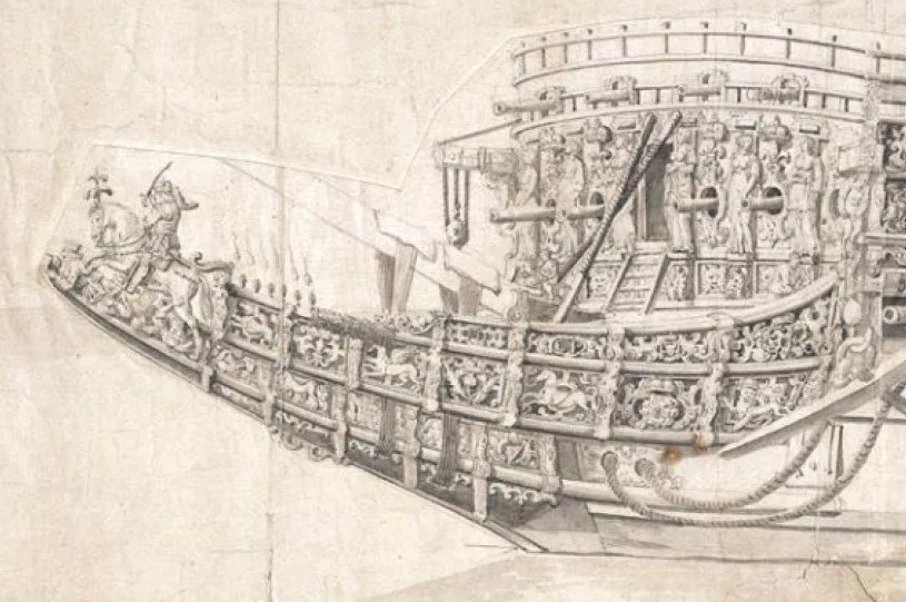

- 321 replies
-
- 2
-
-
- Sovereign of the Seas
- Airfix
- (and 1 more)
-
Wow! That's the nearest I have yet seen, on any model, to an accurate interpretation of her stern decorations. Well done! Trevor
-
I agree: I probably won't matter. But a sail that has to stand up to the wind needs its free edges (i.e. ones not supported by a spar or stay) aligned to either warp or weft. (Otherwise the bias stretch would ruin the shape.) As you have them printed on paper, the two jibs are "mitre cut", with the warp aligned to both foot and leech. (Or should be, though the one labelled just "jib" has one part with cloths aligned to the luff: Bad mistake by the kit manufacturer!) Each jib has a mitre seam from clew to luff, where the two directions of the cloths meet. You might want to try replicating that by making each jib of two triangles of cloth, then joining them along the mitre seam. Or not. As you say, it probably won't matter. Trevor