

Seventynet
-
Posts
735 -
Joined
-
Last visited
Reputation Activity
-

 Seventynet reacted to thibaultron in 3D Printing Cannons in Resin
Armstrong Cannon Graphics - Part 1.
18 Pounder 96
18 Pounder 108
24 Pounder 108
24 Pounder 114
32 Pounder 114
32 Pounder 120
42 Pounder 114
42 Pounder 120
-
Seventynet reacted to thibaultron in 3D Printing Cannons in Resin
Armstrong Cannon Graphics - Part 1.
I added the barrel lengths to the graphics, and converted them the black and white, so the dimensions showed better.
3 Pounder 54
4 Pounder 60
4 Pounder 72
6 Pounder 72
6 Pounder 78
6 Pounder 84
6 Pounder 90
6 Pounder 96
6 Pounder 102
9 Pounder 84
9 Pounder 90
9 Pounder 102
9 Pounder 108
12 Pounder 90
12 Pounder 102
12 Pounder 108
-
Seventynet reacted to Chuck in Sloop Speedwell 1752 by Chuck - Ketch Rigged Sloop - POF - prototype build
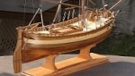
The figure is off scale for the model but looks really good just with the fire hearth. So I made a mini diorama of sorts to display on my desk. I used the old second hand aged stove, LOL. Its one of Chris' figures as you would recognize.
-
Seventynet reacted to Chuck in Sloop Speedwell 1752 by Chuck - Ketch Rigged Sloop - POF - prototype build
Step by Step...
1. Laser cut cedar brickwork. Lightly sand the char. But not so much that you remove the etched mortar lines. Just a little. Especially on the edges of the pieces. Many have bricks etched on both sides.
apply wipe on poly when finished...this is important to seal the wood a bit.
2. Yes its bright!! But this is just the initial steps. I used a red promarker, you can see which color to add the base coat of red to all faces of the brickwork. Also note the two pieces that make up the sides have been glued together. Make sure you have the holes and pieces facing the correct direction.
3. Glue the sides to the back wall. Keep nice right angles. Also add the front piece. This is left a bit long and you will have to trim it to fit. DO NOT glue to the base. This will be done much later in the project. Much, much later.
4. Using weathering powder add some red/brown colors and dark browns to suit. It depends on how weathered you want to go with the fire hearth. You will see this at the end. Spray all the pieces lightly with some matte spray fixative when you are done.
5. This is where the magic happens. You could use white weathering powder but that would also pigment the bricks. You dont really want that. So instead use regular white flour. Brush it on and push it into the mortar lines which are made pretty deep for you. Dont go for a perfect even coverage here. Experiment a little. Push it in the cracks with your finger....pack it in there. Then brush it off the brick faces with a light touch. Experiment for the look you really want...use some additional weathering powders if you want to add soot and ash. Make it a used hearth or a relatively new one!!! Also note the frame on the base was painted black. Dont spray with fixative. The normal humidity in the air will fix the flour in position on its own. It may take a day or so depending on the weather.
6. 1/32" brass wire/rod (not included) were blackened and added as shown above.
7. The hood...laser cut from 1/64" thick boxwood. Glue the shorter back piece on the base first. It should be a at a perfect right angle vertically and centered.
8. Add the two sides. You will need to bevel the bottom to sit flush on the base.
9. Add the front piece...which is taller than the back piece. Note how the front hangs over the the front of the base just a bit. That is done on purpose. It is correct.
10. Finally add the top and front pieces. apply filler to all the cracks and sand smooth for painting. Also build the stack the same way and prepare for painting.
11. Hinges are laser board. Construct them in the sequence shown above...left to right. First add the bottom half of all the hinges. Then the hinge pins are glued along the top edge. Use 24 gauge black wire for that. To finish that up, set the top half of the hinges above the wire. An eyebolt is also added in the center. You can see that in the photos below of the finished fire hearth. There are two of them shown...
A beat up used and weathered fire hearth....and a shiny almost new hearth. Have fun with it and weather to your preferred tastes. LOL
NOTE....the hearth is NOT glued to the base yet. And the stack is NOT glued to the hood yet. It is best to keep them separate for now.
-
Seventynet reacted to Stuntflyer in Sloop Speedwell 1752 by Stuntflyer (Mike) - Ketch Rigged Sloop - POF
Hull planking (prep)
One of the things I've been wanting to do was to see whether or not I could get away without having to spile the hull planks from 3/64" sheet. I was hoping that I could just edge bend boxwood planks to match a spiled shape. With that in mind I ran a test to see if indeed it could be done.
The sequence is a little off since I thought of taking the photos after some of the steps were completed. I retraced the steps as best I could. For better viewing I have focused in on a smaller area of the hull.
The first thing I did was to attach the hull template to my hull. I ran some 1/4" striping tape along the lower edge of the template and then back masked the upper edge of the tape. After that the original layer of tape was removed. You can see a bit of the back masking at the stem. I could have just drawn a line along the bottom of the template instead of using tape. Being a test of only one plank, I didn't want to do that. Hey, that's just me complicating things.
Here is the back masking (original taping removed) where the lower edge will line up with the upper edge of the plank.
I traced the lower edge of the tape (the shape for the upper edge of the plank). This gives me the shape needed for spiling or hopefully just some edge bending. You should be able to see the pencil marks across each frame.
The resulting shape resembles a gentle "S" curve. Something like this.
I was able to edge bend the boxwood to match the spiled shape without any difficulty. Clamping the test plank to the hull was done without having to do any twisting or bending. Mission accomplished!
Mike
-
 Seventynet reacted to Chuck in Sloop Speedwell 1752 by Chuck - Ketch Rigged Sloop - POF - prototype build
Finishing up the platforms with the ringbolts for the scuttle lids. I also made a quick mock-up today of the fire hearth. Unlike the Seawatch books I am deviating from the traditional stove. I have built a lot of traditional iron stoves in my time. Based on the original drafts and on the draft for the similar sloop Fly I am going with a brick fire hearth. The contemporary draft is shown in the photos below. You can clearly see the bricked up hearth. I think it is a much more interesting fixture and its something I have never modelled before. You guys can go either way...its up to you. But I will only be making a mini kit for the fire hearth for the model. This was actually very typical for sloops of this time period and I found a great deal of source info for these.
All of the brickwork is lasercut cedar. The hood parts are thin boxwood sheet with laserboard hinges. I will of course have to make another because I didnt take step by step photos. I used a really easy and neat technique to weather those bricks. I will detail that when the time comes.
The fire hearth isnt permanently added yet. I will however glue the base onto the platform at this time.
-
Seventynet reacted to Chuck in Sloop Speedwell 1752 by Chuck - Ketch Rigged Sloop - POF - prototype build
I wish I had a foolproof method. I faced the same issues. Multiple scrap pieces and do-overs. The only advice I can give is to not settle and make a new deck beam when one doesnt fit. The plans are pretty accurate but everyone will fair the inside of the hull differently so they are always going to be custom fit.
Honestly I just eye-balled the length making them slightly longer to start and then slowly sanded the ends until they fit. Each pass I made slight adjustments to the angles on each end. If I over did it…then I tossed it and started again. Thats what ship modeling is all about…at least for me.
You guys didnt see my many do-overs, LOL.
If there is any silver lining…I will be completely planking these lower platforms. So the beams wont be seen anyway.
-
Seventynet reacted to Chuck in Sloop Speedwell 1752 by Chuck - Ketch Rigged Sloop - POF - prototype build
Before I can begin placing the beams for the lower platforms, I must make a height gauge first. There are many ways to do this and a system will be very important to have moving forward on this project. Greg describes one method in his books on Speedwell. I have decided to go another way. I prefer to make a depth gauge of sorts.
Here is a photo...you folks can of course select any method you prefer. I am fond of this one and such a gauge can be made with readily available scrap strips...Note how the pointer is a separate it to be slipped onto the lower shaft. It is basically a very large T-square. I used 3/32" thick strips but they are fairly wide so they wont bend or flex. The center of the "T" is thinner at about 1/16" thick.
The pointer is meant to be slid onto the center shaft of the "T". Everything is squared up and at perfect right angles. Nice and neat.
Basically take the measurements from the plans to find the depth of any beams etc. Like the forward platform beams. The underside of the "T" is set flush with the sheer on the plan. Then I mark the top of the platform beam on the center shaft...without the pointer on it. Just a pencil tick mark.
Then the pionter is added to the shaft and lined up with the tick mark. The pointer must fit nice and snug so it doesnt shift around. Its a very tight fit on purpose. Then the depth gauge can be brought to the model as shown. Repeat on both sides for each beam end. I am marking the height for the tops of the beams. Find where that beam should be and mark its height on the model. Repeat this process for every lower platform beam end. Then connect the marks to find the proper height for the platform. Basically repeat this on both sides. Hope that makes sense.
I am basically trusting that my sheer on the model is correct and even on both sides. I am confident...
But if your sheer is off you have bigger problems anyway. No matter what method you choose there will be issues. This is just one method that can be used. I did this for all the lower platform beams which are 3/16" x 3/16" cedar. That is except for the most forward platform which has 1/4" x 3/16 beams just under the stove. Check you plans carefully. The beams have no roundup and are just cut from strip stock. They are carefully measured and shaped to fit snug. Placement is important here.
In fact the placement of the first 1/4" x 3/16 beam of the forward-most platform is very important. It is exactly 5/16" away from the beam aft of it on the lowest platform. So a small jig was laser cut to help find its location. This will be provided. It sits on the lower platform beams which went in first. It has laser etched marks to help you place that first beam in position correctly at the right height and the right distance from the lower platform beam.
Once all seven of the forward platform beams were in place I tested my placement with the a cutout of the plans. Everything is level and the plans fits pretty darned good.
Next up is to add the a bulkhead and some additional framing on these platforms before I plank them.
Hope this makes sense...
Chuck
-
Seventynet reacted to Martes in Age of Sail 2 - 3d ship models for PC wargame
Some stills from running a rather silly gunnery run - just shooting up some boats - with the Hyperion. Hopefully they might convey the ship's dynamic:
-
Seventynet reacted to Chuck in Sloop Speedwell 1752 by Chuck - Ketch Rigged Sloop - POF - prototype build
The next step was to create the bulkhead on the lower platform. This was laser cut. All I had to do was cut some 1/8" x 1/8" strips to simulate the vertical beams. I just cut them to length and glued them on. Now this piece may not actually fit your model perfectly. There are just too many variables. It all depends on where you placed that first platform beam. It also depends on how you faired the interior of the hull. But I sure it could be tweaked in most instances. If you had to, you could use this as a starting point template to make another. It isnt very difficult to do.
This is a picture of the bulkhead glued in position. It is glued on the forward side of that first platform beam. The templates are there to help me during the next step. I will be adding the carlings and ledges. They can be taken right from these templates which are on the plans.
Here is a photo of the ledges and carlings completed. These will support the scuttle lids once planking is finished. I plan on planking the entire platforms. I think it will make creating the various cabins a lot easier.
Planking is underway with 5/16" x 3/64" cedar strips. I am not too concerned about getting up close to the sides of the hull. Depending on how fairing went, this could sometimes lead to a weird shape along the edge of the platform. So I concentrated on making a nice shape with the outer edge of the platform deck planking since the sides of the hull inboard will not be planked. I am getting close to the side though and creating a consistent shape port and starboard. It will be impossible to see the sides of this planking when done. Once I get this done I will add the metal work (eyebolts with rings) for those scuttle lids. Then its onto the two aft platforms which are done in a very similar way. Also note the two cut-outs for the legs of the riding bitts. The planks were cut so I could slip the riding bits down into those slots...hopefully!!!
Somebody asked to see a wider shot of the hull with the depth gauge in position. So here is a picture of the hull all dusty after finishing the planking on those forward platforms. Dont hesitate to ask me any questions.
-
Seventynet reacted to thibaultron in 3D Printing Cannons in Resin
Here is a chart of the Fredrick Cannons that will be available: The Orange blocks are cannons listed in the 1760 list, the Blue are those added in 1764, The Red are cannons that were shown in the drawing I used. This chart is from the Web Site I found. I will make a similar chart for the Armstrongs listed in an earlier posting in this thread. The Armstrongs will be the same cannon designs, but with a touch hole, rather than a flash pan.
-
Seventynet reacted to Chuck in Sloop Speedwell 1752 by Chuck - Ketch Rigged Sloop - POF - prototype build
Work has started on the interior. Not much in this initial step but it was good to get started again.
First up was to add the limber strakes. In the photo below you can see the completed limber strake below the keel. This was made up up three lengths. Above the keel you can see the 3 lengths not yet glued into position. They are laser cut for you and are 3/32" thick. There is a laser etched rabbet which runs along the inside edge. Each of the three lengths were first sanded free of laser char. This included carefully sanding the rabbet more or less. But it doesnt have to be completely clean. This will be completely covered up in some areas with the lower platforms anyway. But do your best. You might also notice the little ….long, triangular pieces called Limber Fillers for lack of a better term. They were glued to each limber strake ahead of time. They are at the extreme ends fore and aft. Dry fit all three lengths in position first. This is important. Make sure they are lined up with the correct frames. You can take their positions on each end from the plans.
The center limber strake was added first. The ends are 5/32" away from the keelson. So it was just a matter of taking a scrap piece of wood 5/32" thick to use as a spacer when gluing it in position. This is shown below. Once again...make sure you position it in the correct spot and use the plans to find which hull frames this should line up with. Its good practice because so many items moving forward need to placed in the correct spot...the hull frames are a great reference to start with. Once the center segment was glued in place the two end sections followed. Make them the same port and starboard of course. But you may also wish to pre-bend these before you glue them in position. Especially at the bow and stern sections. There is a little bit of twist to these and it is always better to not force them. It is so much easier to pre bend and twist so no forcing of the limber strakes will be needed to get them to sit flush against the frames.
With the limber strakes completed, the mast steps can be assembled and installed. I would also note that I didn't bother treenailing the limber strakes because it will just not be seen. But you can do that if you feel compelled.
The mast steps are laser cut in three layers to make life easier. Glue up the three layers first and remove the laser char. Once they are nice and clean, check their fir over the keelson. You should get a nice tight fit and the sides should fit snug down on top of the limber strakes. Note how the outside edges of the mast steps follow the shape of the limber strakes. You should sand them as shown in the photos and plans. The main mast step is shown below. You can clearly see the three layers. Dont worry about the char in the mortice for the mast. Leave that as is. The main mast step also has little wedges fore and aft as you can see. These are laser cut for you. They were glued into the correct position on top of the keelson. This is important!!! place the mast step in the correct place or your masts placement will certainly become problematic.
A small length of 3/64 brass rod was used as the pin to "lock in" the little wedges after I glued them all in position.
A look at the mizzen mast step...no issues here other than the fact that the sides of the mast step have more shaping here. They also follow the outside edge of the limber strakes. I have not applied any finish inboard at all up to this point. I actually might not apply any finish. I will wait to see how things develop first.
An overall view of the mast steps and limber strakes. I will not be adding the limber boards, choosing instead to follow Greg's construction and to simplify the building process. "Less is more" when you leave the framing visible below the wales. You wont want to see much stuff between the frames when you looking at the outside of the hull. It could start to look sloppy with too much interior details and glue showing between the frames. So I will follow the style as outlined in the Seawatch books for the most part.
Next up the forward lower platforms!!!
-
Seventynet reacted to thibaultron in 3D Printing Cannons in Resin
Here is a graphic of the drawing I was given for the Armstrong Pattern Cannons, with barrel and overall lengths. They closely match the data I have for the Fredrick Pattern Cannons, which were basically the Armstrongs with flash pans added. This is the best resolution I can post with the 1600X1200 pixel standard of the forum.
If you have good drawings for other sizes of Armstong, I will consider drawing them. The drawing I have for the Fredricks is similar, with a few changes in the number of each size cannons. The data I have for the Fredricks, is just that data, the drawings are too pixelated to use. I will have to generate new drawings from the Fredrick Standards, and that will take time. If all the Armstrong and Fredrick cannons were produced in the same sizes, and you have data to show this, I can eventually produce all those sizes. It has not been a trivial task to CAD the Brown, Armstrong, Fredrick, Blomefield, and 1718 Spanish cannons, please cut me some slack.
-
Seventynet reacted to thibaultron in 3D Printing Cannons in Resin
Finished redrawing the Armstrong Pattern 1725 to 1759 cannons. As I received the 3D drawings, they had a lest detailed barrel. The drawings were made up of cylinders of 24 facets for a full circle. This made obvious flats on the print, when printed at the larger scales. In the graphic below, you can see the cruder faceted barrel on the right, with 24 facets per circle, and the better breach area with 48 facets. Even 24 facets, gets slightly noticeable at 1/24th scale. For later cannons I drew them at 72 facets per circle, but for these I had some limitations with reusing parts of the original drawings.
I will be posting the STL files in the next post. You are free to use them for your private use. For commercial use, please contact me. I don't plan on asking much, if anything, for commercial use.
I can also print cannons for you in scales from 1/24th to 1/100th with my resin printer. I do not think lower scales will print well on my printer.
Hopefully all my cannon files will be available in a database in the near future.
Here are the drawings of the Armstrong Cannons, for the sizes I have info for.
6 Pounders:
9 Pounders
12 Pounders
18 Pounders:
24 Pounders:
32 Pounders:
-
Seventynet reacted to Stuntflyer in Sloop Speedwell 1752 by Stuntflyer (Mike) - Ketch Rigged Sloop - POF
Square tuck
I wanted to give this a try at least once before making use of the laser cut versions. #1. I copied the angle from the laser cut piece onto the joined strips. #2. The frame was made and set parallel with the angled line. #3. The curves were done with the spindle sander and disc sander along with a bit of hand work. #4. Almost ready to place on the ship. I Still needed to taper the frame.
The most difficult part was trying to get symmetry between the two sides. It's not perfect, but certainly close enough. I was kicking myself when I noticed that the top of the port side square tuck is 1/64" lower at the stern post compared to the other one. Of course this won't be seen once the moulding is on. I left the outer area of the frames without any tapering. There is a tiny filler plank that goes between the tuck and the first strake. I will wait until that's on the ship, so I can sand that area all at the same time.
Anyway only one shot at it for this result.
Mike
-
Seventynet reacted to Stuntflyer in Sloop Speedwell 1752 by Stuntflyer (Mike) - Ketch Rigged Sloop - POF
As you know, Chuck faired the hull with the top jigs in place. After supporting the hull with some planking, he was able to remove the jigs and add the fairing caps for both shape and support. Through hands on experience he knows that this approach will work out nicely. I wasn't so sure that it would work out the same for me. I was concerned that after removing the top timber jigs, I would find myself having to fair the hull a lot more. This would be quite difficult with the planking already on the hull. With that in mind, I decided to take a different approach.
I added a chock between each frame where they would be covered by planking. Adding the chocks meant that I could pull the laser cut top timber jigs (before doing any planking) while maintaining support for the frames. After adding the fairing caps, I could fair the hull more accurately at the shear. Generally this turned out to be true at least for me. There were some areas at the shear that needed more work, but an inch or so below the shear the fairing work was good. Yes, a few hours of extra work that turned out well in the end.
Notice that there is still enough room for the .025" cap rail to sit just below the top of the transom.
There was an enormous amount of work needed to fair these aft cants. It took me the better part of three days. Remember this is boxwood, not AYC. Anyway that's done now.😁
Mike
-
Seventynet reacted to Stuntflyer in Sloop Speedwell 1752 by Stuntflyer (Mike) - Ketch Rigged Sloop - POF
Window sills
I will admit that these were quite tricky to make. Different angles everywhere and some trial and error was needed in order to get them just right. I probably had 3 or 4 throwaways before getting the ones you see here.
Stern frames
In order to make these, I sandwiched two roughly cut frames together with some Elmer's School Glue and then adhered the plan drawing for final shaping. This was easy enough to do with the help of the spindle sander, disk sander and scroll saw.
Transom
On top of the shear there will be a 5/32" fairing cap and a 1/4" cap rail that sits on top of that. The two pieces will add a total of about 3/32" more height to the top of the shear. I wouldn't want the cap rail to protrude above the top edge of the transom. With that in mind, I decided to fair the quarter deck shear before adding the transom. This way I could check the clearance before adding the transom. It was really just a matter of getting that small triangular piece taken down to the right height while fairing the shear.
I added the 5/32" fairing cap for the quarter deck and faired the outer hull using the cap as a guide.
Mike
-
Seventynet reacted to Stuntflyer in Sloop Speedwell 1752 by Stuntflyer (Mike) - Ketch Rigged Sloop - POF
Framing (final pieces)
I have finally finished all of the framing. About nine months to do them all including about 160 milled scarph joints. It certainly feels like a milestone. Though mostly done, I still need to do some minor cleanup fairing, especially where the cants transition into the deadwood.
FYI: Here is the fit that I was shooting for when adding the last frame, #29.
Mike
-
Seventynet reacted to thibaultron in 3D Printing Cannons in Resin
Part 7
Having finished correcting the supports, I moved onto saving the work. Select the “Export” button at the top of the screen. New windows will pop-up on the right.
The first thing to do is save the supported model! This allows you to make new print files without having to start from scratch, as well as place multiple models on the build plate, for printing multiple cannons at the same time. A 3D resin printer takes X amount of time to print a model Ymm high, it does not take any more time to print several models placed on the build plate, than it takes to print one of whichever the tallest one is. So restarting Lychee and placing several of the supported STLs on the plate, will give you many models in the same time. I’ll show this later. For a big model like this it might be better to print just one to start, to verify that the supports are correct. Then print multiple ones, after it checks out, just to save on resin. If you have several different size or type cannons to test, print a group of one of each, to save time.
Select the “Export to 3D File button, and save the file as you normally would.
If you have the free version, the program will display a short advertisement then illuminate a button to continue. I have the paid version, and I forget just what the button says.
Now we need to discuss Layer Height. By default most 3D resin printer set the layer height to 50um, to decrease printing time. We want the best detail though. As I wrote earlier we set the angle to 45 degrees. For my printer, the layer height should be set to 35um. When you first setup your printer, it will ask you to also setup the resin type files. I will not go into that here, as you should already have done this to test your printer, and dial in the correct exposure settings for that resin at the default 50um. All this is explained in the 3D printing thread I mention earlier. As you decrease layer height, you also need to decrease the UV light exposure time, as the thinner layer hardens quicker than thicker ones. Look through that thread. Use the spreadsheet, in that thread to find the correct exposure time for your new layer height, and save it under a new name like the one shown in the “Export Slices” window above and below, that I made for the 35um layer height. The blue ".pwma button may have a different label, as the print file type may be different for your printer.
Select the “Export the slices to file” button, enter the file name, and select the “Save” button. Lychee will create a slice for each layer section of the model (in this case one for every 35um layer), then create a print file containing all the slices that will work for your printer.
The program will display each slice as it works its way through the model. You can watch this and see if everything looks OK. This takes several minutes so sit back and relax! This model will take 2785 slices as shown at the top of the window. The present slice being shown is also displayed.
This graphic shows one of the slices for this model. I tried to take several screen shots from this first run of the process, but Lychee and a scheduled virus scan were using 100% of my CPU, so I was unable to go back and forth between Lychee and my photo program, to save multiple ones. The picture shows a level a little above the top floor of the raft. The outline is that layer of the angled raft wall, and a cross section of the supports.
The next few graphics are from the second and third Lychee runs that I used to replace some of the messed up screen shots from the first version.
Luckily the run did not take as much CPU percentage as the first, and I was able to get a few screen shots from it. Note the lack of the Heavy supports shown in these pictures. These were actually from my third attempt at getting screen shots.
This slice is from the breach end of the cannon.
This one is just above the breach.
This picture is a layer at the level of the trunnions.
This picture is a layer of the barrel near the muzzle.
This one shows a layer through the fancy fluting at the muzzle. Note the dot inside the bore. This is a section of one of the internal supports.
When the slicing is finished, this window will be displayed. Take the estimated time to print, with a grain of salt. I’ll explain below.
I just exit out of this window, opening the file folder, is something I do through Windows Explorer before I exit Lychee, just to make sure everything is where I expect it to be.
Lychee will now display the following window showing data about the print at the bottom left of the window.
The text is shown blown up below.
The important things to see here are to check that:
1. The correct printer is shown, this is doubly important if you have more than one printer!
2. The correct resin and layer height were used.
3. The time estimate is probably wrong, I’ll talk more about this later. Generally, at present, my printer takes about twice as long as the number shown.
4. If you select the “Estimate resin volume”, the program will calculate this for you. I don’t know why this is a separate calculation, rather than just doing it automatically, but it does take a little bit of time, and the program was originally written for commercial users. Maybe they don’t want to take the extra time in the commercial world to wait for this when a large complex model is being run.
If you do select the volume calculation, you will get a break down of total volume of resin needed, as well as a breakdown of the model and support volumes. It also gives you a cost based on the price of resin you entered while doing the resin type setup.
Here is a picture showing a close up of the internal supports.
If you are going to be printing more than one model in a single print it is best to arrange them so that the pulling forces are balanced as the build plate retracts. This helps to insure a good print. As an example here is a good layout for printing two of these cannons in one setting. This setup is one of the things I was talking about when I said to save the STL (or OBJ) of the supported model. I imported the second model from a previous session.
As a note: Even though I imported the second model from a saved Lychee session, it was flagged as having problems. I simply ran the Lychee correction script, and it fixed the model. This has been a frequent problem I have encountered with Lychee, but there was only one time it was unable to fix the imported supported file. Later in this thread, I will be discussing AutoCAD’s Netfabb program, in regards to both fixing STL and OBJ problems and for scaling either.
Now, about the incorrect printing time. Lychee is supposed to take your printer data from a database they have, which includes print speeds. For my printer, which was just released when I setup Lychee, they got it wrong! Additionally they have a “History” database in the program itself. However, after you create a print file, the next time you open Lychee, they will ask you about the print that you made from that previous file, including the actual print time. If you didn’t record that time, or have not yet run the file, it retains the calculated time in that database, as valid. I have constantly forgotten the record the time, in my hurry to clean, cure, and gaze lovingly, if it worked, at my creation. I often also create several print files, between print sessions, so that history database has a mishmash of corrected and calculate times in it. Hence the print time problem. If that database was correct, Lychee would be able to give a better estimate. Knowing I have to double the time, is good enough for me. 3D printing takes time, and I am doing hobby stuff, not paid commissions. This printer allows me to make models I would have a lot of trouble doing myself, especially if large quantities are needed!
-
Seventynet reacted to thibaultron in 3D Printing Cannons in Resin
Part 1
So, you want to 3D print some cannons, you have the files, but don’t know where to start. I hope this will help you get started.
You found a drawing of the cannons you need for your ship or diorama.
Unfortunately, you do not know how to make these into a 3D drawing. However, you have found someone who has already done this, and you are able to get copies of the STL or OBJ files (files that are formatted for 3D display or printing) from them). Where do you go next?.
Below is an example of this cannon’s 3D drawing using the SketchUp program. Note that in the drawing above the dimension shown is from the end of the muzzle to the breach (bottom of the bore), while the dimension shown below is the overall length of the cannon.
Here is a picture of the STL file for this cannon.
This is a screen shot of a different cannon, after a OBJ file has been generated from the original drawing in Fusion 360. Both OBJ and STL files have a similar format.
You can see that the cannons have been changed to a series of triangular surfaces. All the information on the size, orientation, location, etc., is what the STL/OBJ file contains. Programs can then convert this information into printer files.
Part 2
Let’s start with the simplest method. You have either a STL or OBJ file in the correct scale, and are sending it out to a commercial printer. It is best, but not required, if you know the correct length for the prototype cannon(s), so you can double check the final scaled dimensions. 3D printers almost always use the metric system, so you need to change that length to millimeters, if it is in feet/inches.
You and the printer can double check that you are getting the proper size cannons. The printer generally has a process for downloading the files to them. Follow those instructions, and let them do the rest. If your file is not in the correct scale, they generally allow you to change the dimensions before you hit the buy button. This is where knowing the correct length comes in really handy. Just putting in a ratio from one scale to the next, is not as accurate as entering a fixed length, due to the fact that they generally limit you to two decimal places in either case. For instance the file is full size, and you want them printed in 1/64th scale. For this example, your cannon is 100” long. So convert it to mm = 2540mm. If you divide by 64, you get 39.6875mm. Rounded to two decimal places, this is 39.69mm. Using the ratio method 1/64 = 0.015625, or a ratio of 0.02 when rounded to 2 decimal places. So 2540 X .0.02 = 50.8mm, not even close. Even if they allow three decimal places of accuracy in a scale ratio, you end up with a model cannon 39.624mm long, close but it still might be noticeable if you are trying to replace some damaged or missing cannons you already have, from say, a kit.
If you have someone who is willing to print them for you, and is willing to do all the setup, you just need to give them the file and the correct length, if you have it.
Part 3
Now we will take the route of either you are just starting out with 3D printing at home, or you have a friend that will print them for you, but does not have the time to do all the processing for you. Note, that it may take two or three trials to get the supports right, so allow for this.
For scale models with good detail, you need to use a resin 3D printer, the filament printers have much too course a “Line Size” for fine detail. The nozzle on a standard filament printer is 0.400mm, with a typical layer height of 0.200mm. A 3D resin printer, typically has a line width of 0.050 to 0.035mm, or less, with a layer height that can be set between 0.050mm and 0.010mm! So 10 times the resolution of a filament printer. The difference is like using thick cardboard layers and a wide felt tip pen, as opposed to layers of thin paper drawn with a sharp pencil. 3D resin printers need supports to print a model, as will be explained later, and these will leave tiny pock marks when removed, similar to injection molded parts, so you will have to paint the cannons, even if they are printed in black resin. You want to do this anyway, as UV light will degraded the resin, or any plastic for that matter, over time.
Both types of 3D printers need processing of the files, before they can print it. Basically the model has to be cut into many slices, as both printers build the model one layer at a time. The filament type printers build up the model by putting down layers of melted plastic, one on top of the other, going upwards from the base of the printer. While thin, these layers are, relative to a small model, quite thick, with visible stair step surfaces. These are great for large models, and for small assembly type parts, such as a new motor mount for re-motoring a model railroad engine, toys, servo mounts, etc. The plastics are more durable to shock loads than resin, which can be brittle.
Any 3D resin print will need supports, as will be explained later. Some 3D filament parts may also need supports, for complex shapes. For our cannons though, resin is the way to go, and I will only cover that method.
First you need to determine if the file is already scaled properly, or do you have to rescale it, because it either represents a full size drawing (1:1), or is the wrong scale (ie. The file is 1/48th scale and you need 1/64th).
You can rescale both STL and OBJ files in Lychee Slicer (one of the more popular (and free!) 3D printer slicers), but there are some checks I run in other programs that I will detail in later sections for these type files. Right now, we will just look at scaling in Lychee.
STL and OBJ files are the standard printable files that are most commonly available. The STL type is the printable file associated with SketchUp. SketchUp’s native file (the file it uses for saving its standard drawings is SKP, like AutoCAD’s DWG, or MS Word’s DOC or DOCX files). When the SketchUp file is finished, you output it to an STL file for 3D printing. Fusion 360 is similar, but its 3D print file is the OBJ file type.
Let’s assume that your file is in the incorrect scale, and you just want to rescale it. I will show you the simple way using Lychee Slicer. Lychee Slicer has a free version that can be down loaded
from https://mango3d.io/downloads/
Open Lychee to import your file.
1. When you first start Lychee, you will get one of two screens.
a. If you have no prior projects started, or it is the first time you have run Lychee, you will get this screen. Simply select the Add File button and select your file.
b. If you had a prior project running when you exited Lychee, you will get this screen, and probably can skip the rest of this section because you are familiar with it. Select “Decline”, and open your file either from the "Add Files" button, the "File" menu, or the "Import" button.
For this example I will be rescaling a 1/24th scale file to 1/64th scale. In the picture below, I’ve opened the file for a 6 Pounder British cannon from the early 1600s, that in full size is 98.8 inches or 2509.57 mm long, or 104.56mm long in 1/24th scale.
Notice that the cannon is gray, if it comes in light or dark red, there is a problem with the file. Generally it means there is a hole somewhere in the object. This can generally be corrected in Lychee.
If it is gray click on the cannon, and the “Object Repair” window should say everything is Ok, continue. If not see directly below.
The window displayed if there are no errors with the model.
The file below has a problem, that must be corrected before you can continue.
In this case click on the object.
You will see the Object Repair pop-up at the right. Select “Repair 3D model”, and let the program fix it. In this case the problem could not be fixed. Go to the Netfabb Section, to see how to repair the problem. Otherwise Lychee will fix the problem, and tell you it did. You can now go to the scaling function.
This is the window that will be displayed, if the repair fails.
This is the window displayed if the model could be fixed. Yes, if you look closely this is from a different model. I know someone out there will notice it.
If there were no problems, the object will be blue. On the left, select the Scale button.
The Scale Window will open.
First, make sure that the “Uniform Scaling" button is selected to “ON”. With this on, any change you make to the dimension of one axis, with be automatically re-scaled for the other two. With the button “OFF” you would have to scale X, Y, and Z separately.
So, the scaling window shows that the 1/24thth scale model is 104.57mm long. The full size length of the real cannon was 2509.57mm, which is a better number to scale from, if you have it. For example, 2509.57/24 = 104.5654, which rounds up to 104.57mm, but if you re-scale from 1/24th to 1/64th, you may be off by a little due to the rounding.
Anyway, for this write up I will use the full length value for determining the correct length for 1/64th scale 2509.57/64 = 39.212mm, or 39.21mm after rounding.
In the “Scaling Window” enter this value into the “X” box, and then select one of the other (Y or Z) boxes. Lychee will now re-scale the whole cannon to 1/64th scale. You will see that the model is now shown smaller on the screen.
Select the “Export” button at the top of the screen. A set of windows will open in the right hand side of the window. Select the “Export to 3D File” button, and follow the prompts, to save the file. Saving the file is covered in more detail towards the end of Part 5.
-
 Seventynet got a reaction from billocrates in HMS PEGASUS by giampieroricci - Scale 1:36 - Swan-Class Sloop from plans by David Antscherl & Greg Herbert
Stunning, beautiful work! Thanks for sharing your incredible skills.
Ian
-
Seventynet reacted to Erik W in HM Cutter Cheerful 1806 by Erik W - 1:48 scale
I thought drawing in the tick marks and drawing the placement of the hook scarph joints wouldn't take too long. Well, after about 12 hours over the last week, I'm finally happy with the way everything looks on the deck, and I'm ready to proceed with the deck planking. Getting the drawn-in planking to look and flow the way I wanted it took so many adjustments and needed to be redone so many times I actually had to go out and buy more erasers! The last redo was actually after these photos were taken. I moved the rear of the aft scarph joints back a bit after viewing the photos, in order to have the taper of the outer 4 planks better match the inner 6 planks aft of the skylight. I also tweaked a couple of other areas after viewing these photos. Since I've never planked a deck before, my goal was to spend as much time as necessary to get the planking drawn in on the deck. Sort of the planking version of adding training wheels to a kids bike, or having bumpers in the gutters when kids bowl at a bowling alley. I'm trying to minimize my chances of screwing the deck planking up since it will be a very visible part of the build. The saying, proper planning prevents poor performance, comes to mind. One note when looking at the photos - since the plank lines were drawn in straight lines between the tick marks, it doesn't flow as smoothly visually as the actual curved planks will.
Erik
-
Seventynet reacted to Erik W in HM Cutter Cheerful 1806 by Erik W - 1:48 scale
Here's my latest progress. I have the five center deck planks installed. These were straight forward since they're not edge bent or tapered, but they took time none the less. As always, the process is going slow and test fitting, then sanding a bit, then test fitting, then sanding a bit, and repeating over and over again until a tight fit is achieved. I'm looking forward to planking the rest of the deck . . . but I'm also looking forward to having all the planking finished and behind me! I did a first sanding after getting these planks down. So if they look rough, that's why. I'll do the final sanding when the planking is finished.
Erik
-
Seventynet reacted to Erik W in HM Cutter Cheerful 1806 by Erik W - 1:48 scale
Thanks for all the 'likes" folks. I spent the last week building the companionway, so I'm now finished with the deck fittings that will be placed along the center line before planking the deck. For the companionway I used pencil to darken the board seams. I also slightly beveled the edges of where the companionway lid and doors are hinged. I applied several layers of much thinned red paint that allowed the board seams to show through. After painting was complete, I used a pin wash made of black oil paint thinned with Turpenoid that I applied to the hinged joints in the lid and doors, as well as around the bottom and side edges of the doors. Annnnnnd . . . . you can't really see any of all that effort in the photos. Super frustrating! I must've taken 30 photos of the finished companionway, with different background colors, and lighting and lighting angles, trying to show the board seams showing through the semi-opaque red paint. What you see is the best I could come up with. The funny thing is the board seams are so pronounced when viewing in person that I had seriously considered painting one more coat of red over the whole thing, particularly on the lid (which you don't see any seams at all in these photos). And I was worried the black wash was too pronounced. None of which you can see in the photos. Can you tell I'm still annoyed? Haha.
At any rate, the next step is gluing all these deck fitting on to the deck. Some other Cheerful build logs have good advice on getting these aligned correctly. After that, it's on to deck planking.
Erik
-
 Seventynet got a reaction from Kenneth Powell in HMS PEGASUS by giampieroricci - Scale 1:36 - Swan-Class Sloop from plans by David Antscherl & Greg Herbert
Stunning, beautiful work! Thanks for sharing your incredible skills.
Ian