HOLIDAY DONATION DRIVE - SUPPORT MSW - DO YOUR PART TO KEEP THIS GREAT FORUM GOING! (Only 24 donations so far out of 49,000 members - C'mon guys!)
×


aydingocer
-
Posts
916 -
Joined
-
Last visited
Content Type
Profiles
Forums
Gallery
Events
Everything posted by aydingocer
-
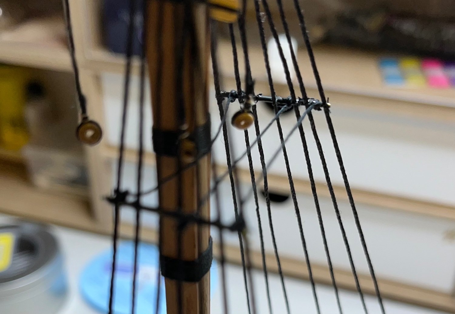
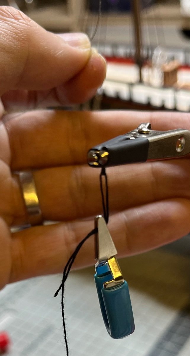
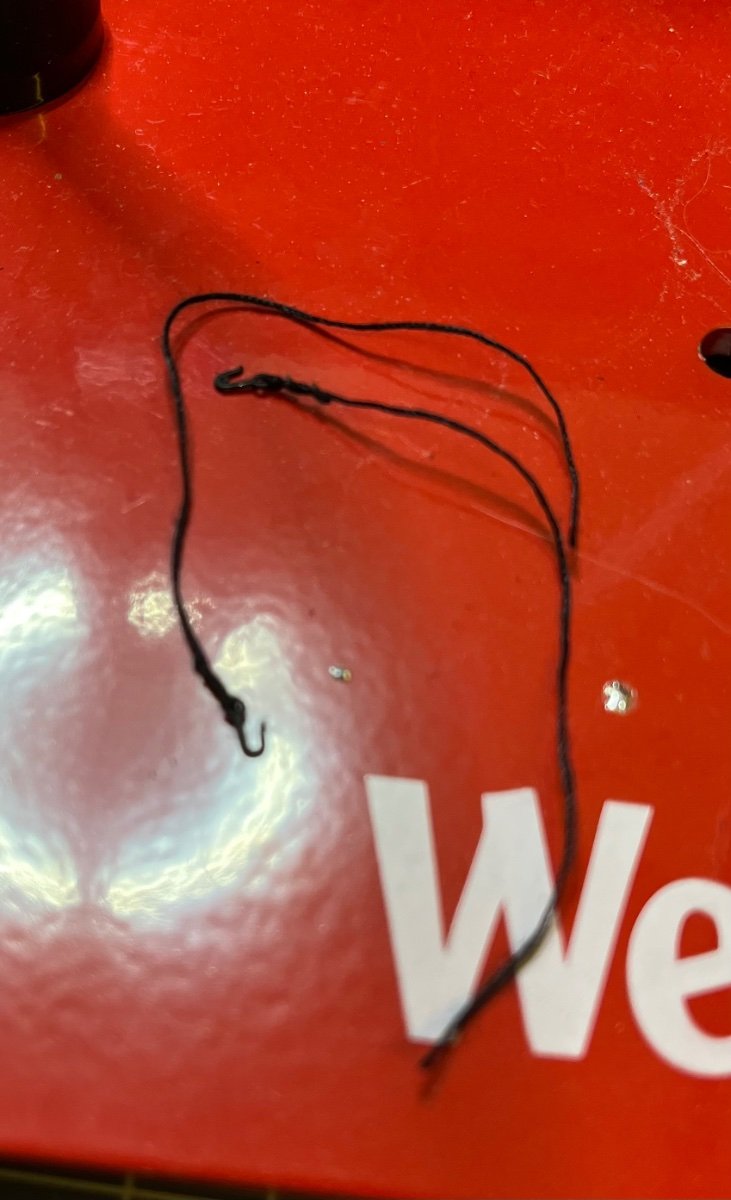
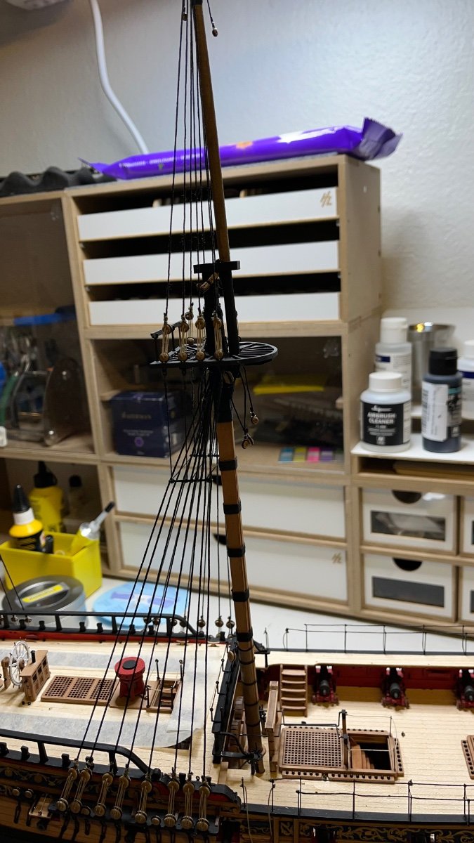
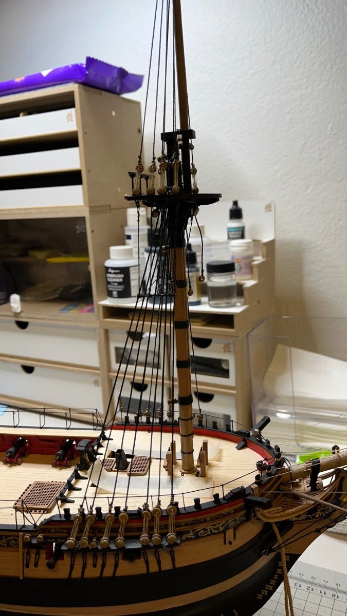
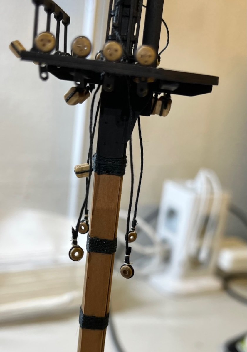
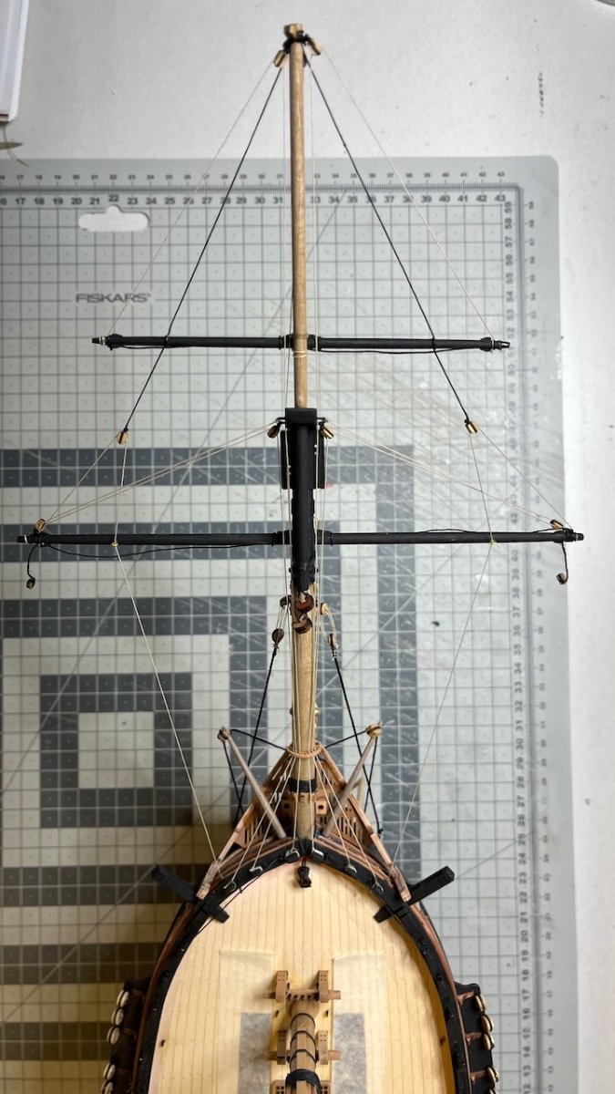
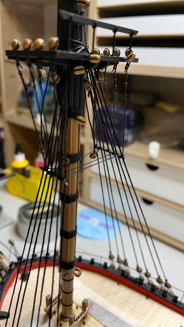
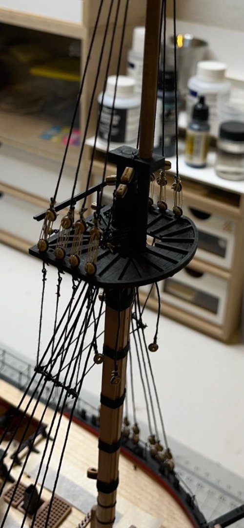
 Build day 133-138: 11hrs / Total 296,5 hours Photos 784-792: More progress after 11 hours of work in 6 build days. With this work I have completed - Catharpins and futtock shrouds, - Upper shrouds. I used mini clamps and crocodile teeth to help align the threads while I am knotting.
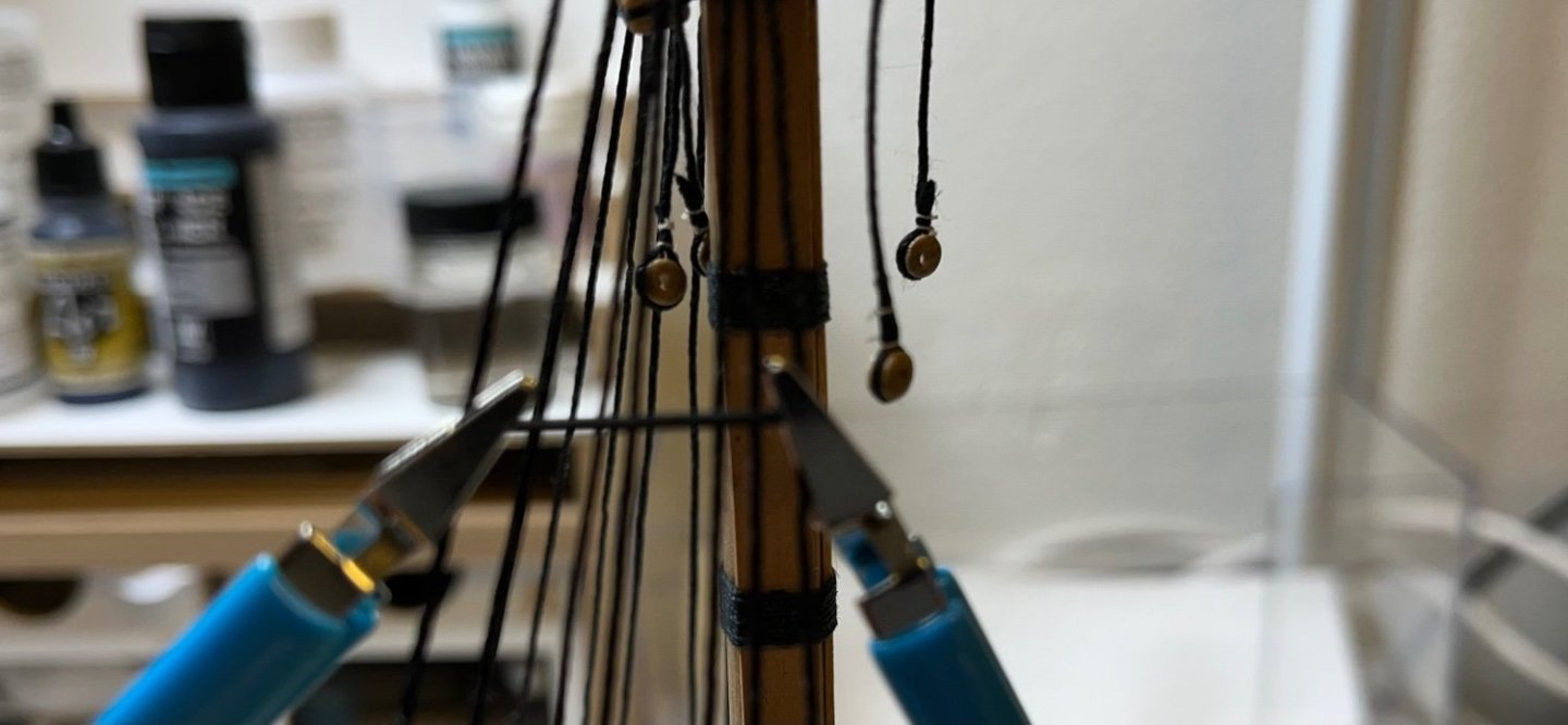


- 426 replies
-
- 9
-

-

-
- Vanguard Models
- Sphinx
- (and 1 more)
-
Build day 129-132: 9hrs hr / Total 285,5 hours Photo 783: It's been a while since my last post. Continuing with rigging. Lower shrouds complete after 9 hours of work spread into 4 build days.
- 426 replies
-
- 11
-
-
- Vanguard Models
- Sphinx
- (and 1 more)
-
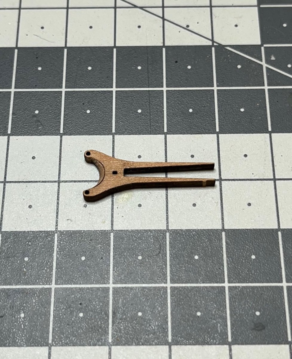
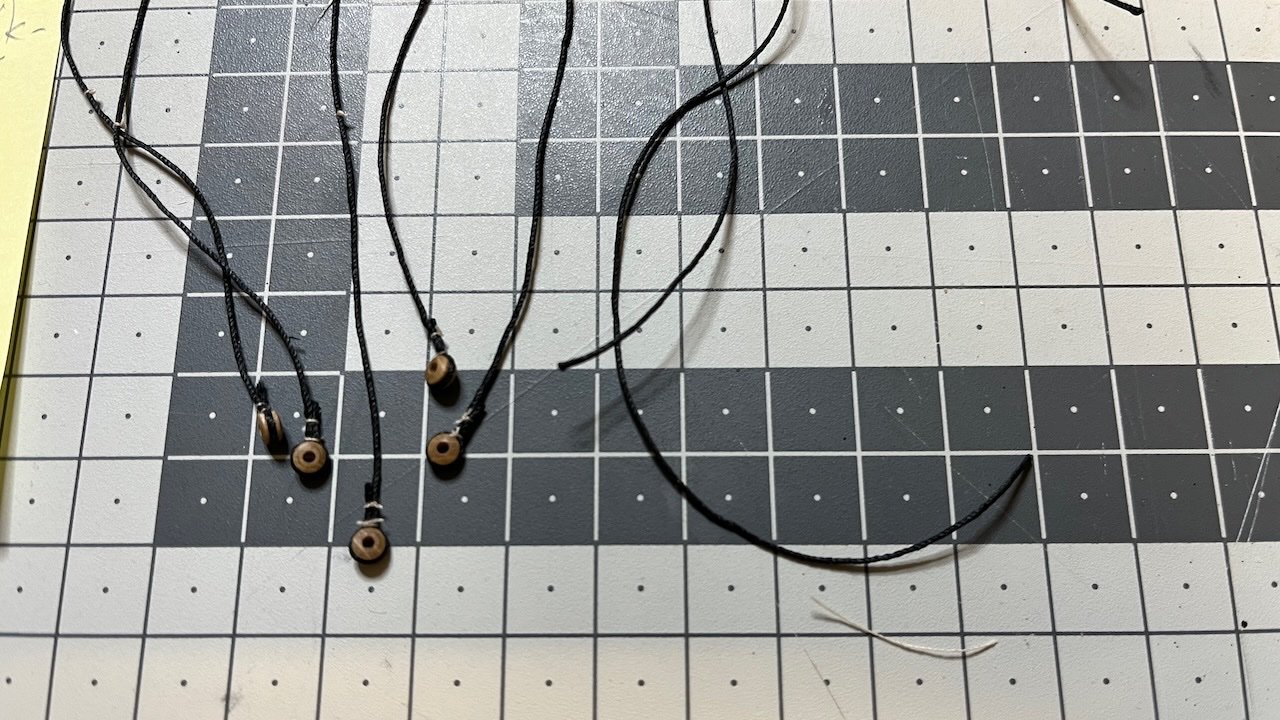
Build days 126-128: 4,5 hrs / Total 276,5 hours Photos 781-782: Pendants complete, before starting the shrouds. Spent a total of 4,5 hours spread into three days. Some photos showing their preparation and in place.

- 426 replies
-
- 11
-
-
- Vanguard Models
- Sphinx
- (and 1 more)
-
Build day 125: 3 hrs / Total 272 hours Photos 779-780: Bowsprit rigging complete (from Rigging Plan Sheet #3) before starting with the ratlines.

- 426 replies
-
- 7
-
-
- Vanguard Models
- Sphinx
- (and 1 more)
-
Thanks a lot once again Glenn. So if I see correct you have tied them directly on the bowsprit itself, not to the blocks.
- 426 replies
-
- 1
-
-
- Vanguard Models
- Sphinx
- (and 1 more)
-
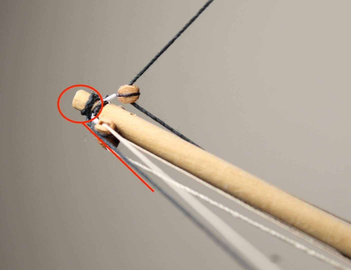
Thanks a lot Glenn, that answers my first question, i.e. it is a 0.25mm natural thread . In sheet 18 it says 650mm but now I see I had read it 65mm and installed too short thread, which confused me. How about my 2nd question about tying the "G" to the block on the tip of the bowsprit? According to the bowsprit plan I did not make any loop to the edge of the block for tying any thread. I wonder if I should just loop the "G" thread around the block. See pictures 1, 3 and 4 above.
- 426 replies
-
- 1
-
-
- Vanguard Models
- Sphinx
- (and 1 more)
-
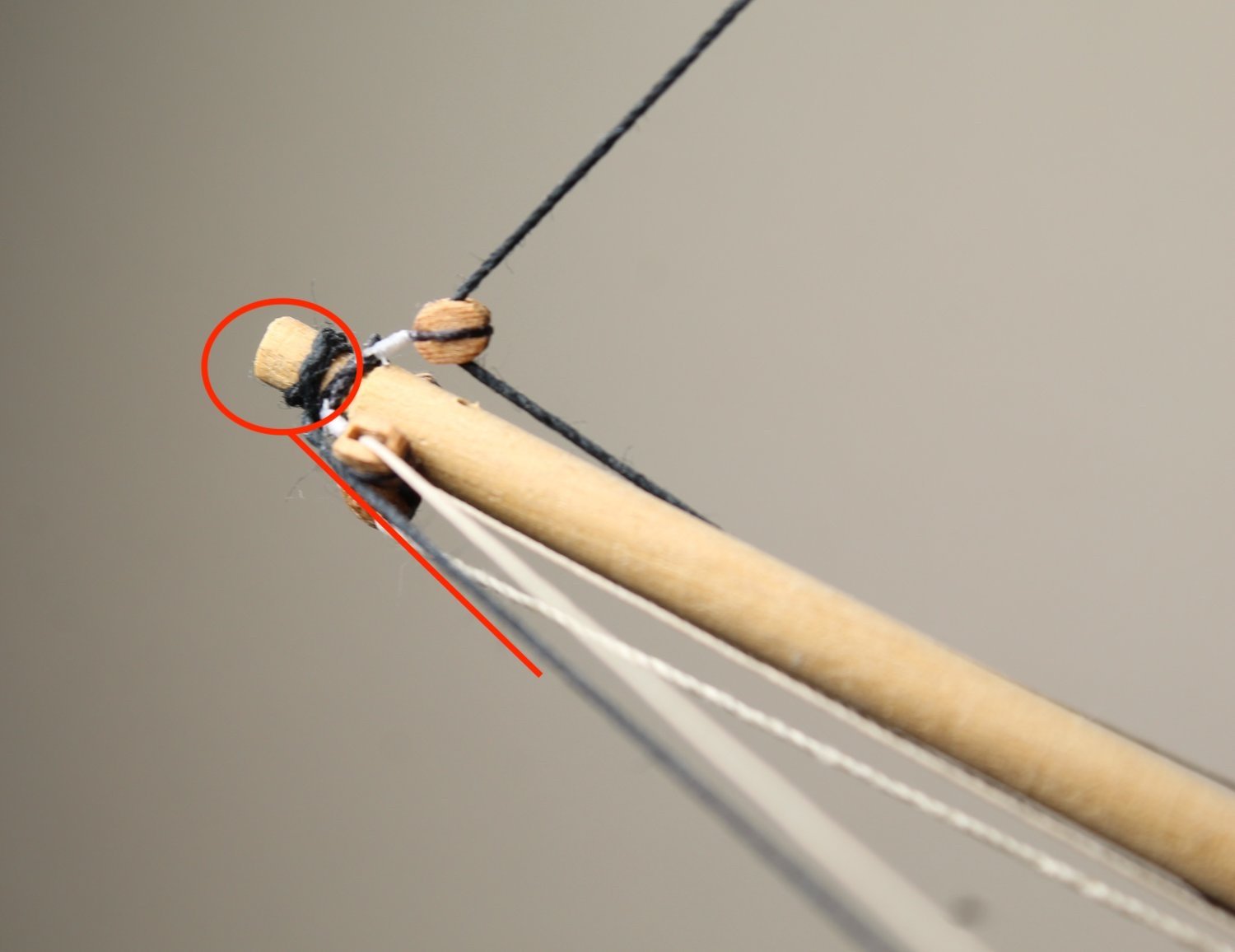
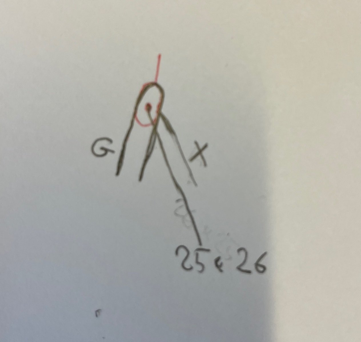
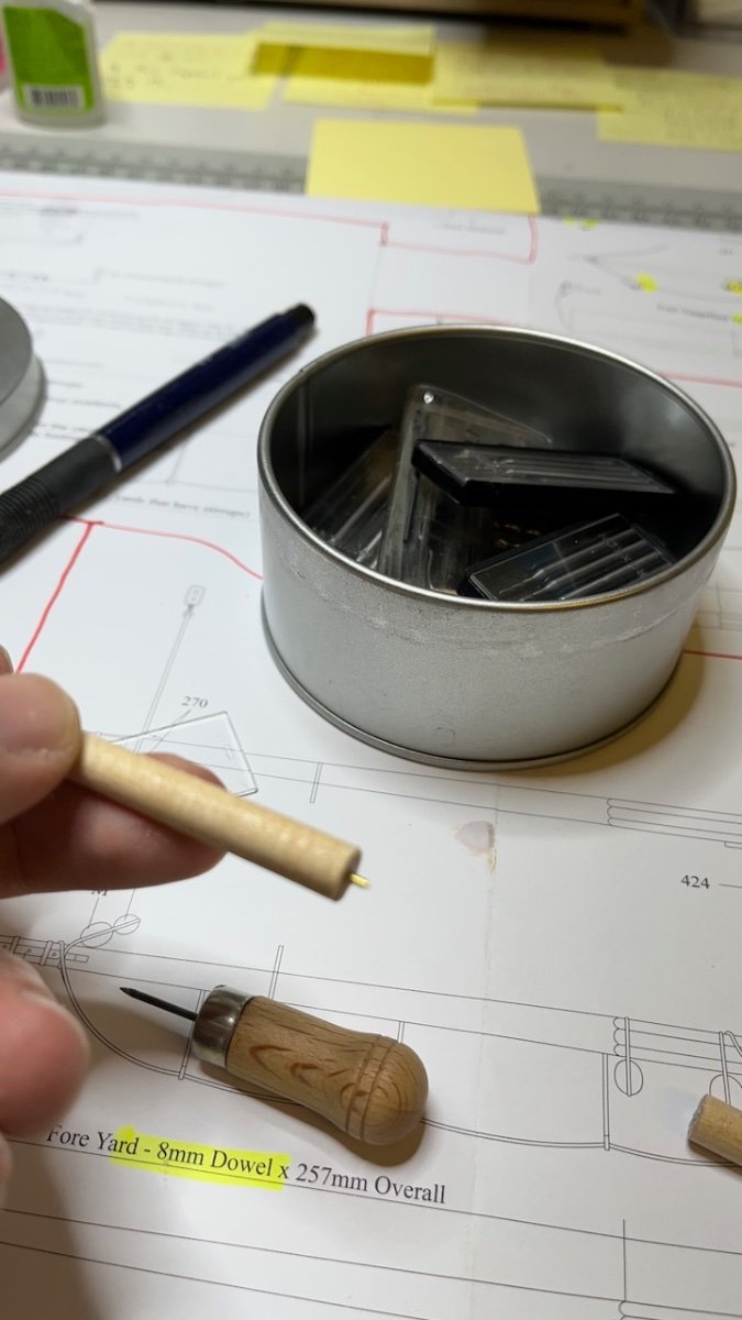
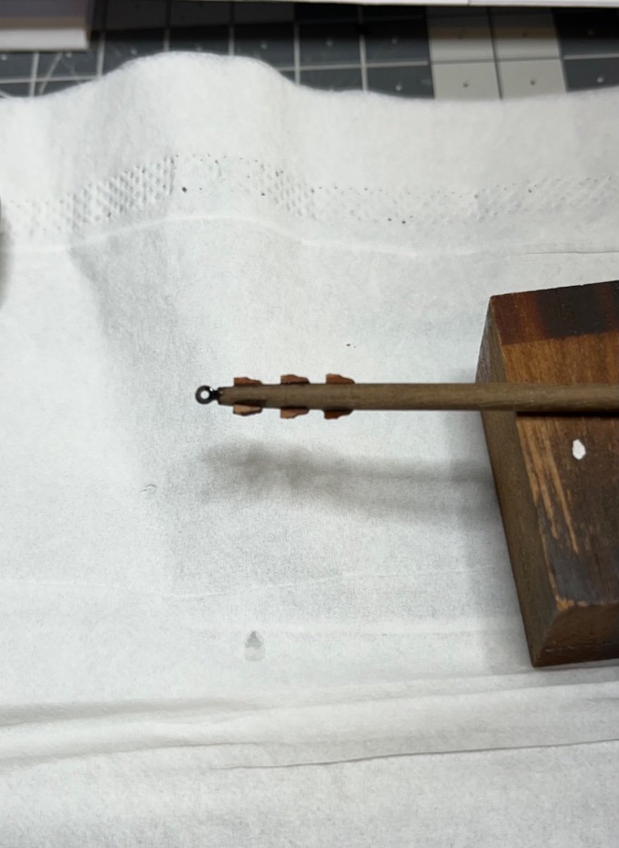
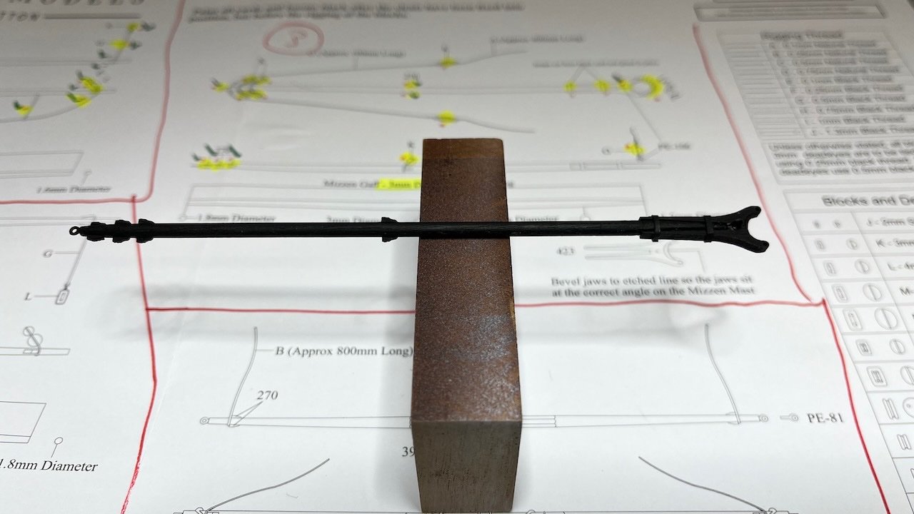
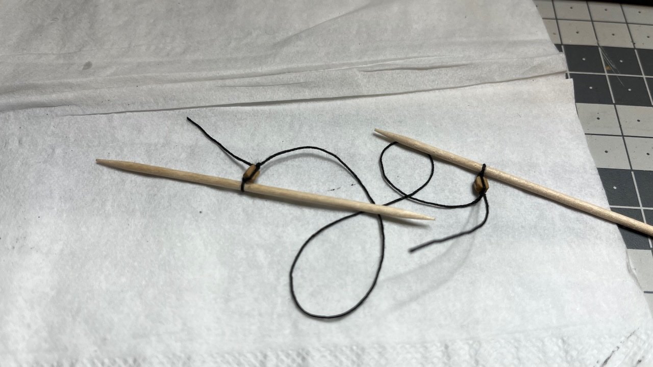
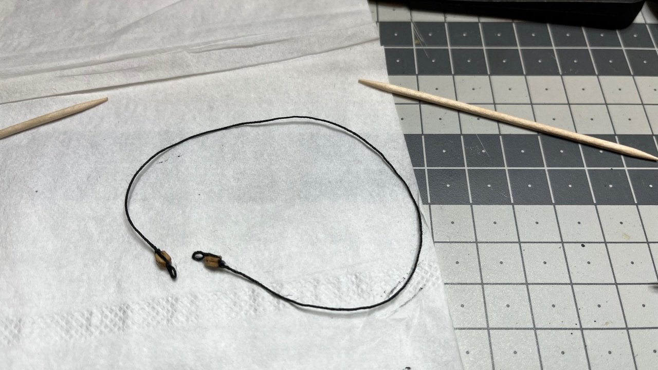
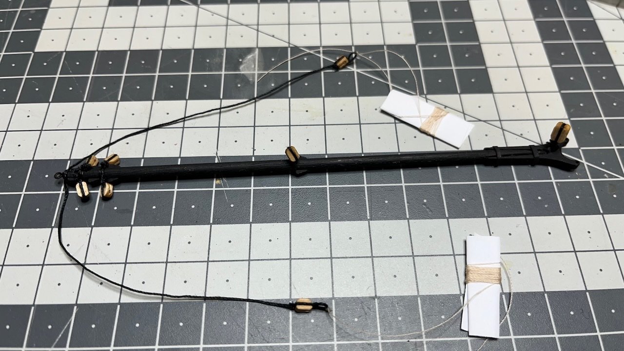
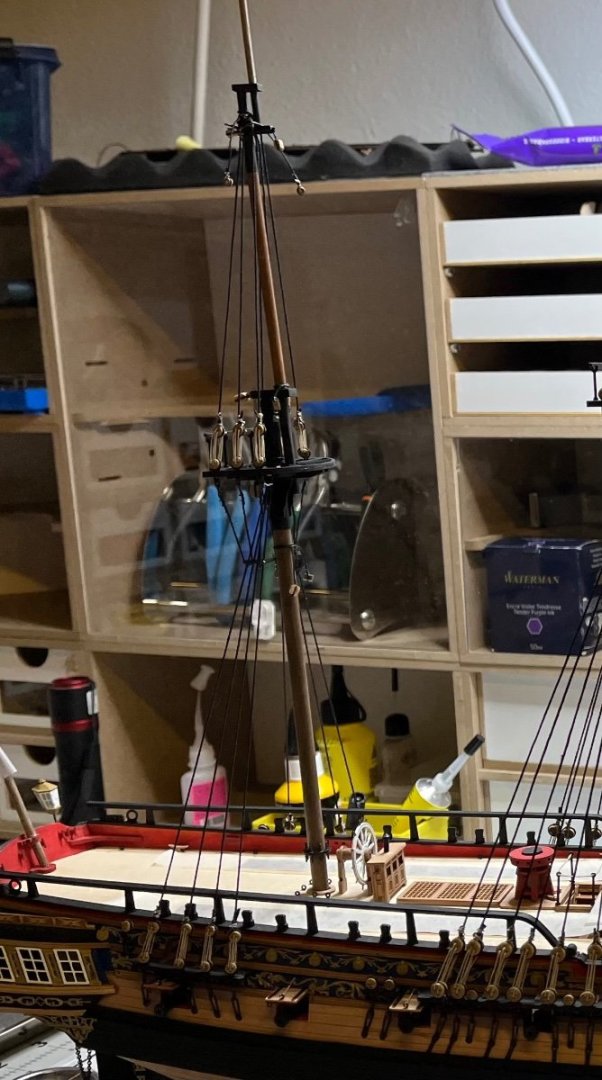
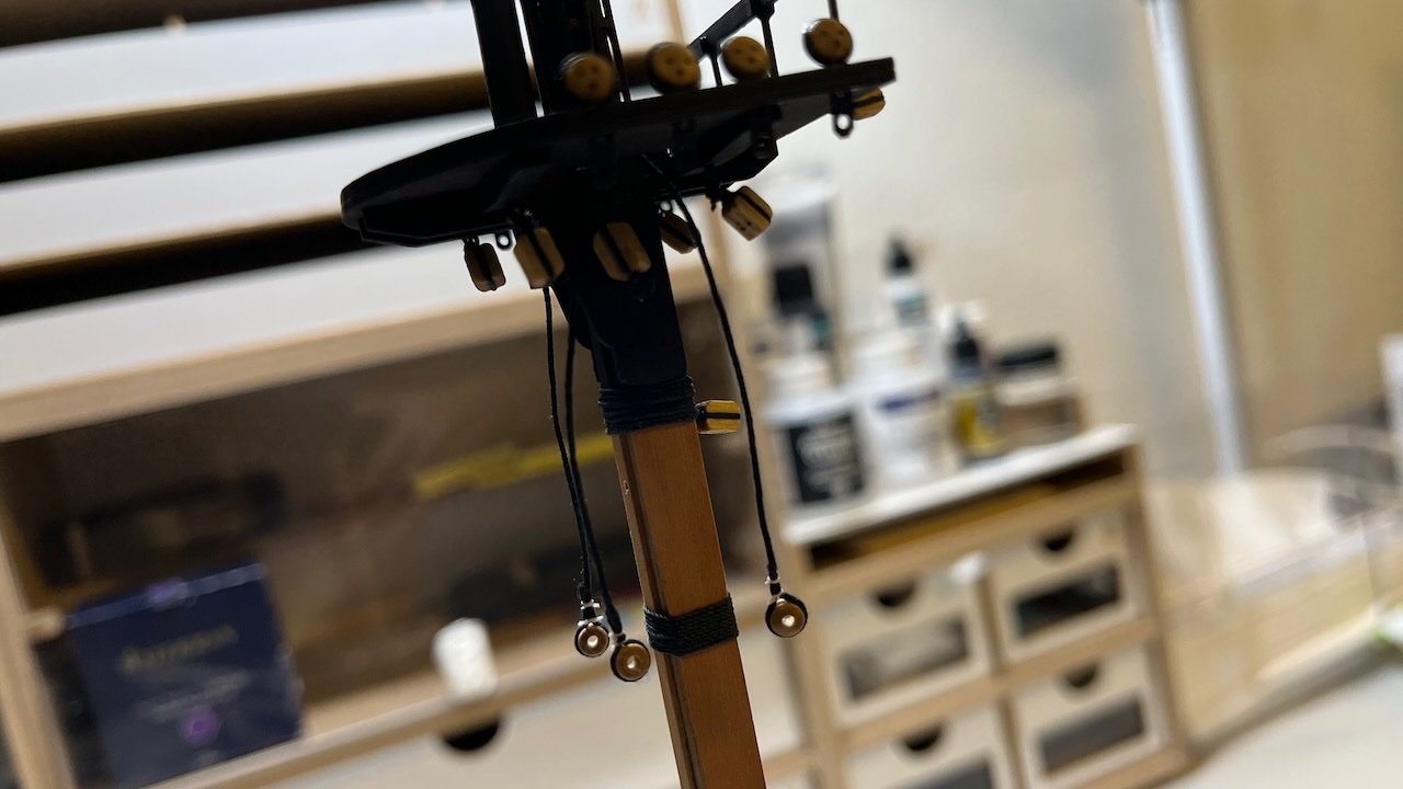
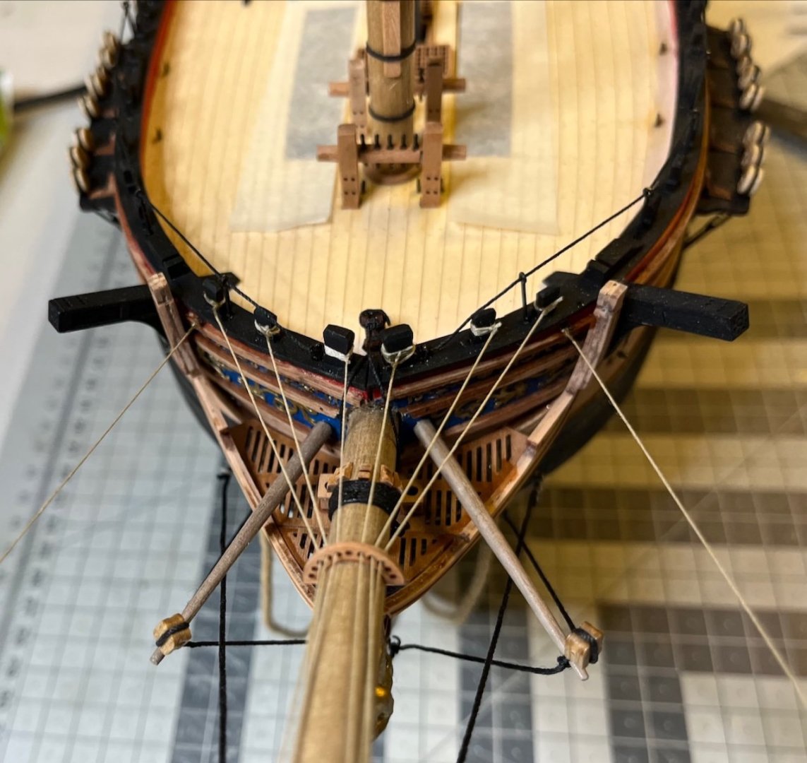
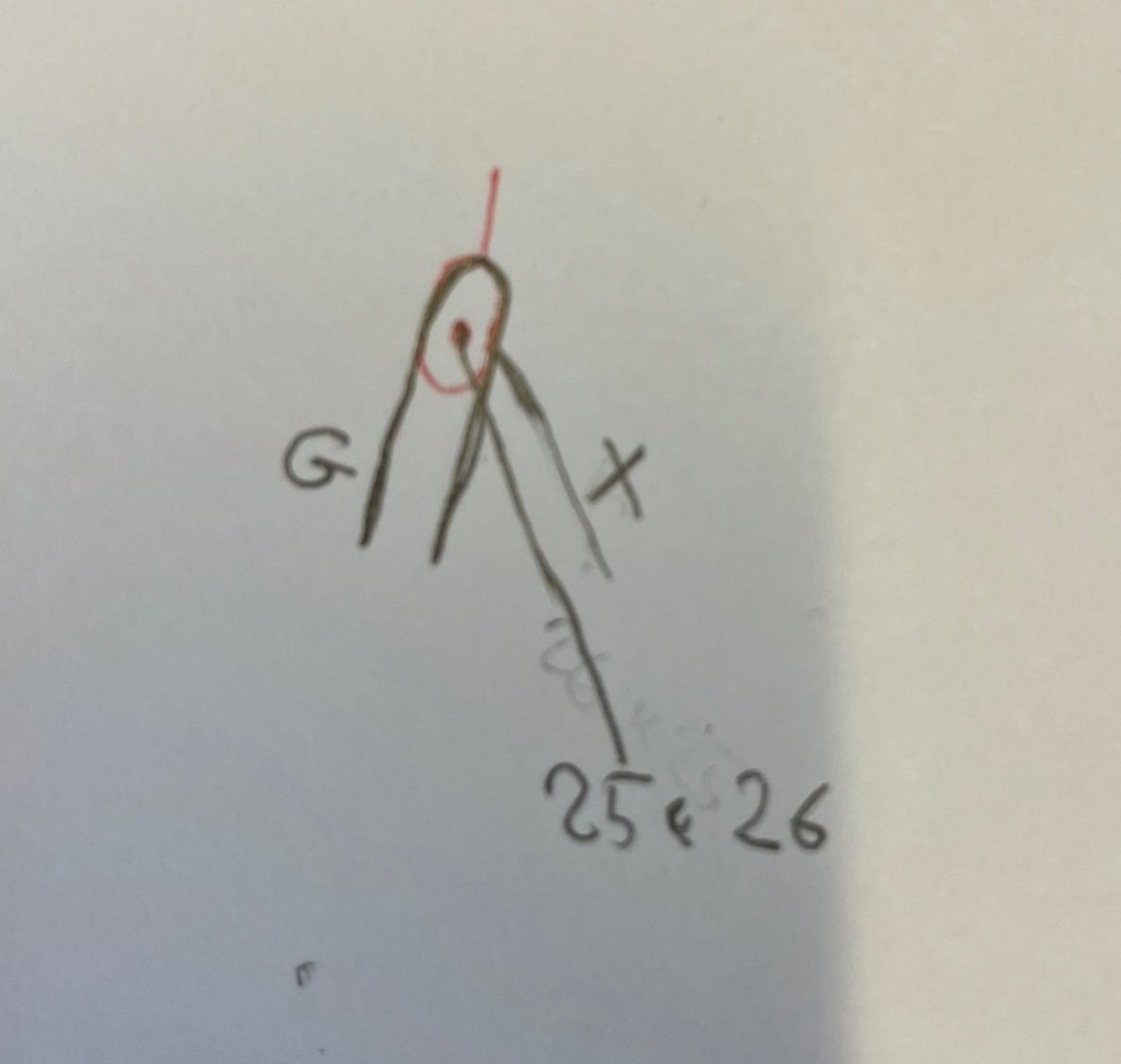
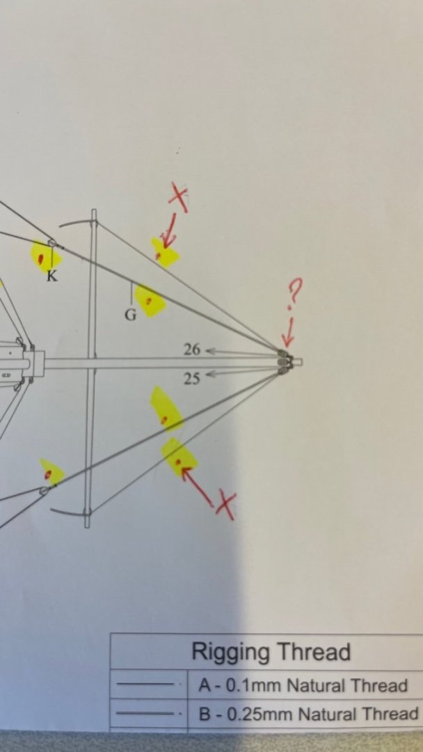
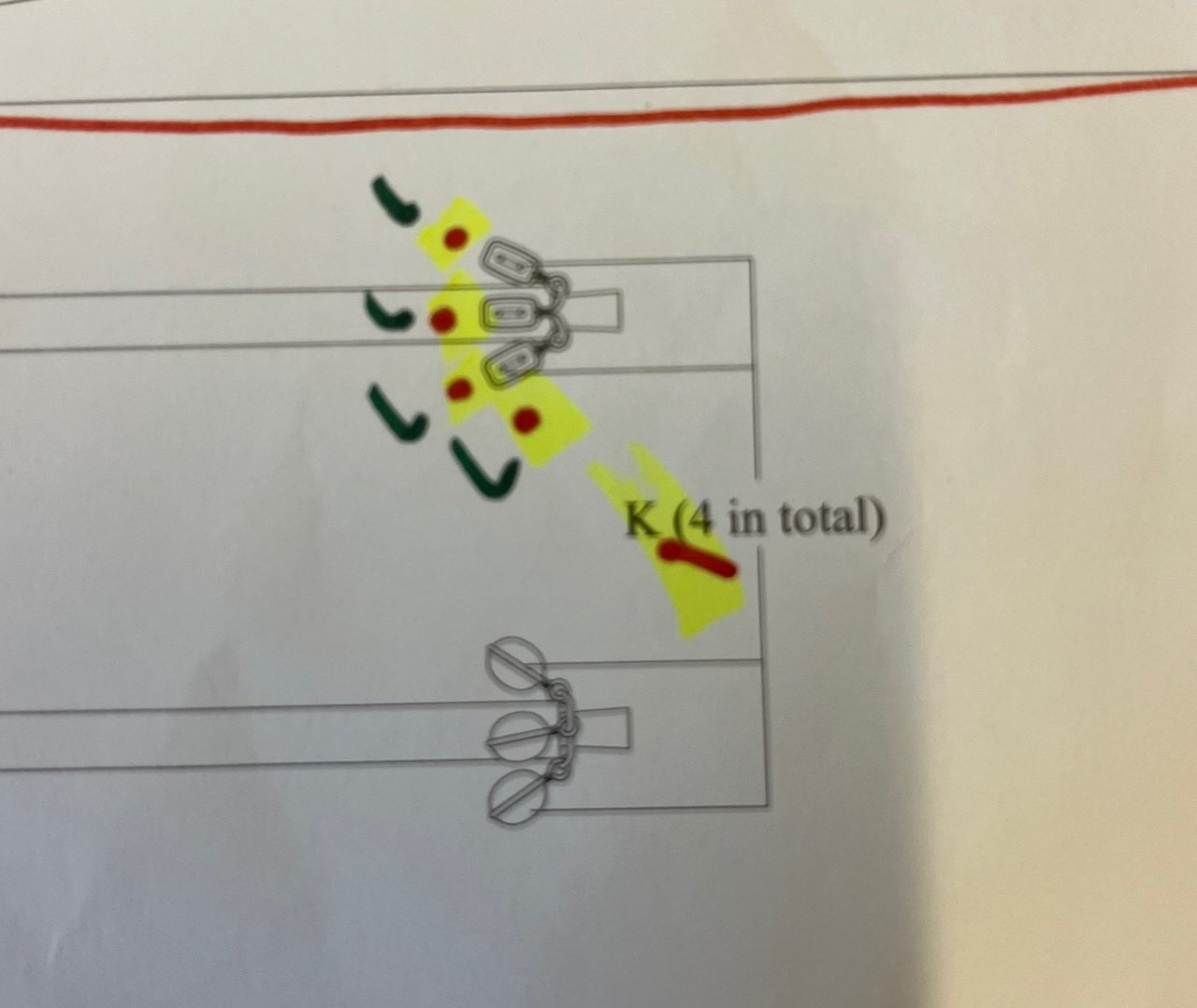
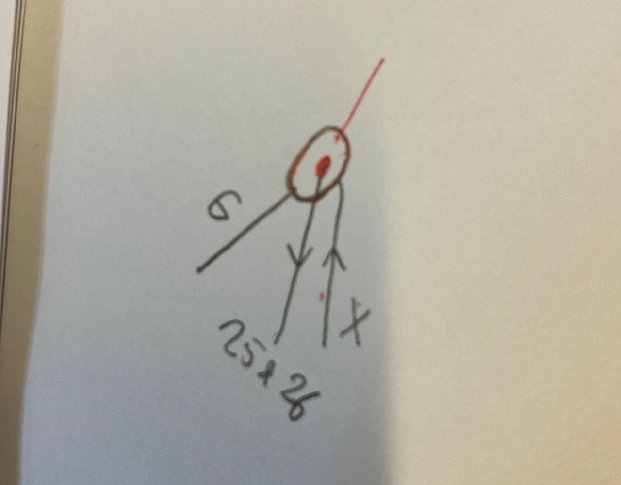
One question about the bowsprit rigging. See the bowsprit rigging plan below. What thread should I use for where I marked with "X"? I didn't find a clue. Second. Also check the second picture for the tip of the bowsprit where I marked a "?" in the first picture. That's how I assume, i.e. the "X" thread goes through the hole and the "G" around the block. Did I get it right? I am a bit confused because the G looks like a single thread that starts from the block. Post EDIT: Forget what I asked about the 2nd picture and check the new 3rd and 4th pictures. Is that the correct way? But if "G" is supposed to be tied to the block, in the bowsprit plan (last picture) there is no hook or loop on the blocks to tie it to. POST EDIT PICTURES:
- 426 replies
-
- 1
-
-
- Vanguard Models
- Sphinx
- (and 1 more)
-
Just following the instructions. It is supposed to be white
- 426 replies
-
- 1
-
-
- Vanguard Models
- Sphinx
- (and 1 more)
-
Build day 124: 1 hr / Total 269 hours Photo 778: Alright. The masts are carefully in place now. Apologies for the noisy background.
- 426 replies
-
- 5
-
-
- Vanguard Models
- Sphinx
- (and 1 more)
-
Thanks Glenn, I've also figured out that it seems to be the way to glue them: where the mast rests on the bottom surface.
- 426 replies
-
- 2
-
-
- Vanguard Models
- Sphinx
- (and 1 more)
-
Another question: How deep should I insert each mast through their slots? Or better way to ask; how high should they rise from their decks? I didn't find much clue in the plans. Using my caliper, I measured the following depts for their slots. Shall I insert them all the way? Fore Mast: 66 mm Main Mast: 39 mm Mizzen mast: 66 mm. Thanks in advance for the answers. /Aydin
- 426 replies
-
- 1
-
-
- Vanguard Models
- Sphinx
- (and 1 more)
-
Gathering from the manual and plans, this is roughly the order I am planning to follow. How does it look? Any advice, warning, suggestions appreciated. Fit the masts Rig lower shrouds Rig upper shrouds Fit the yards (not rigging them yet) Fit the crossjack sling to the crossjack yard (at this point for accesibility) Rig the mast stays (Omit Main Stay Tackle and Fore Hatch Tackle at this stage) Add the Crowsfeet to the mast tops Rig the back stays Rig the yards Fit Sheets and Tacks Fit the Main Stay Tackle (but do not lash done yet) Rig the Yard Braces Fit the ship's boats Lash down the Main Stay Tackle and Fore Hatch Tackle Regards, Aydin
- 426 replies
-
- 2
-
-
- Vanguard Models
- Sphinx
- (and 1 more)
-
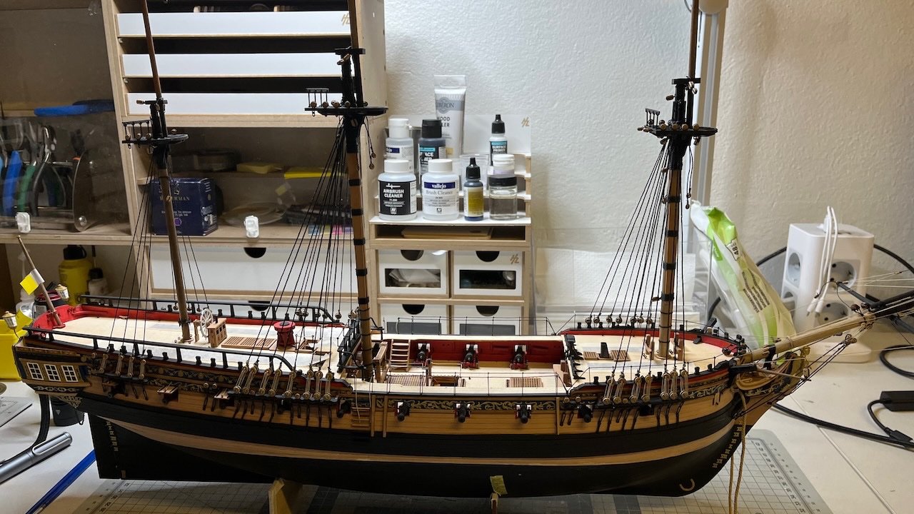
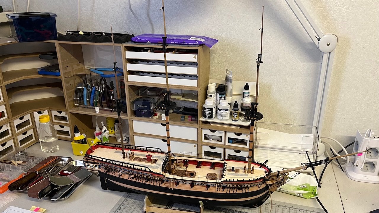
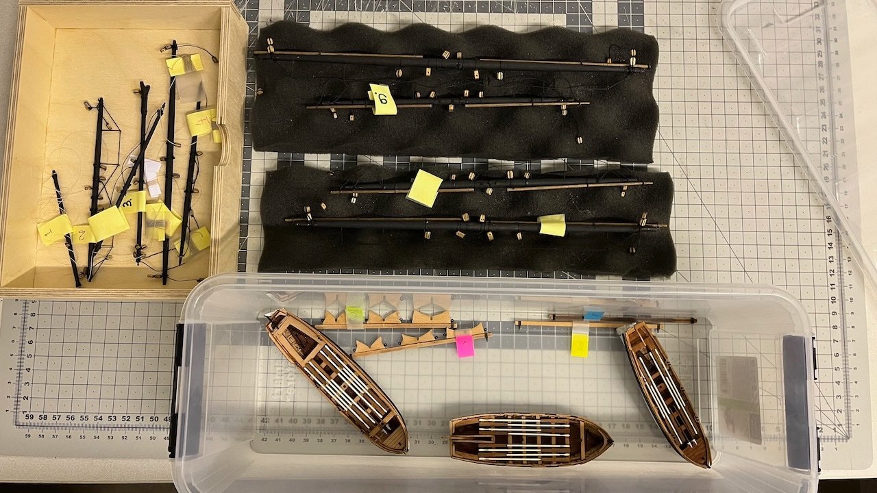
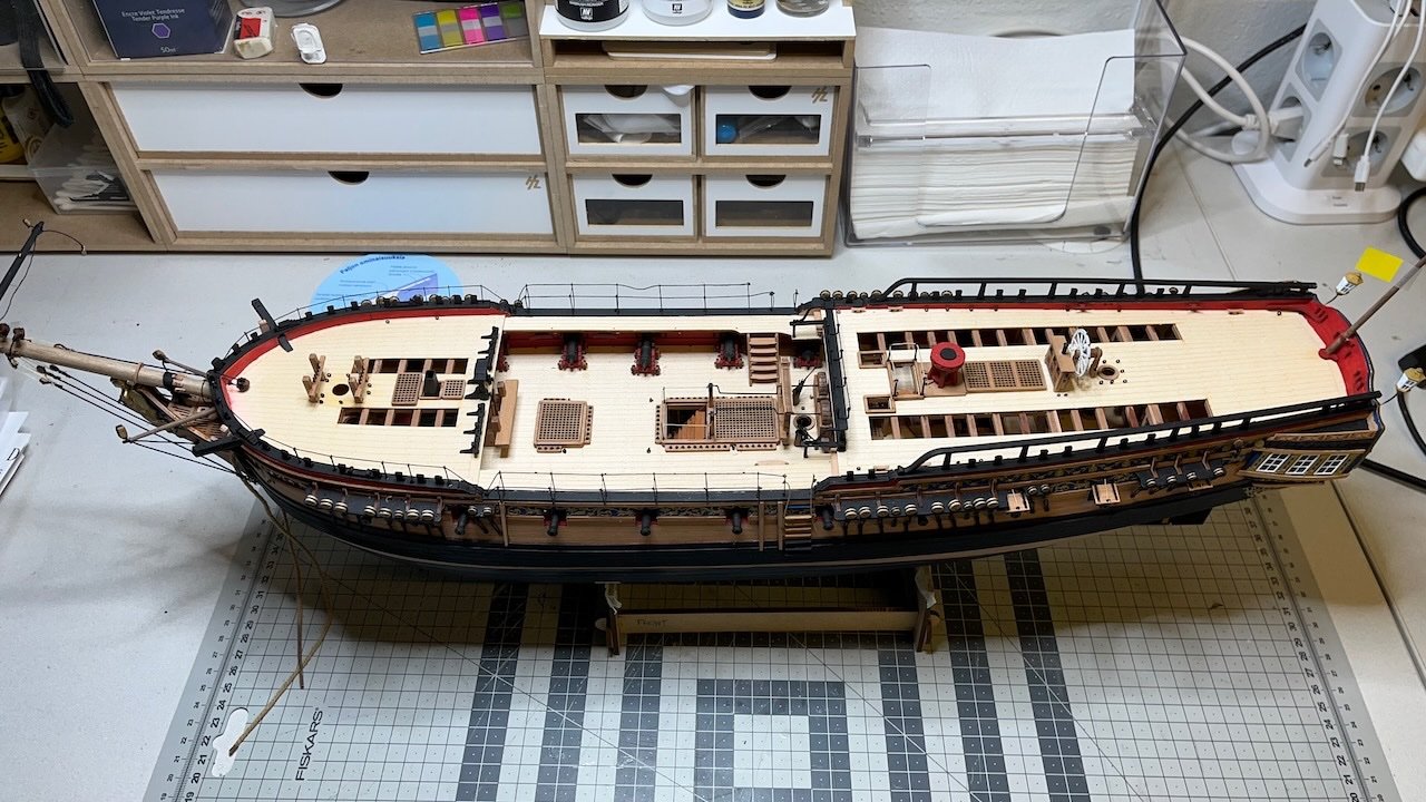
After a short break for some other projects occupying my workbench, my Sphinx is back on the dock. Now all the masts, yards and boats ready, it is time to put them together and start rigging. Photos 775-777
- 426 replies
-
- 4
-
-
- Vanguard Models
- Sphinx
- (and 1 more)
-
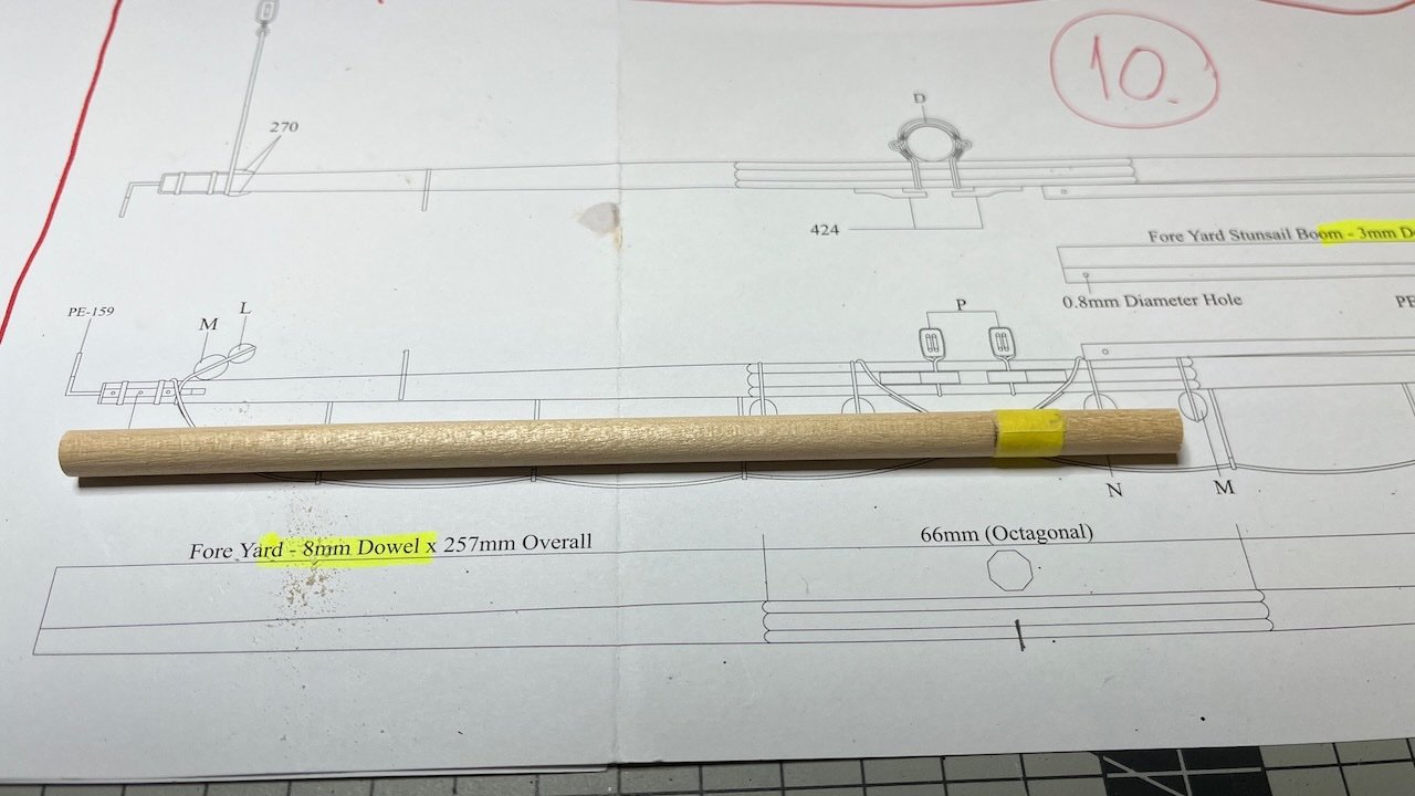
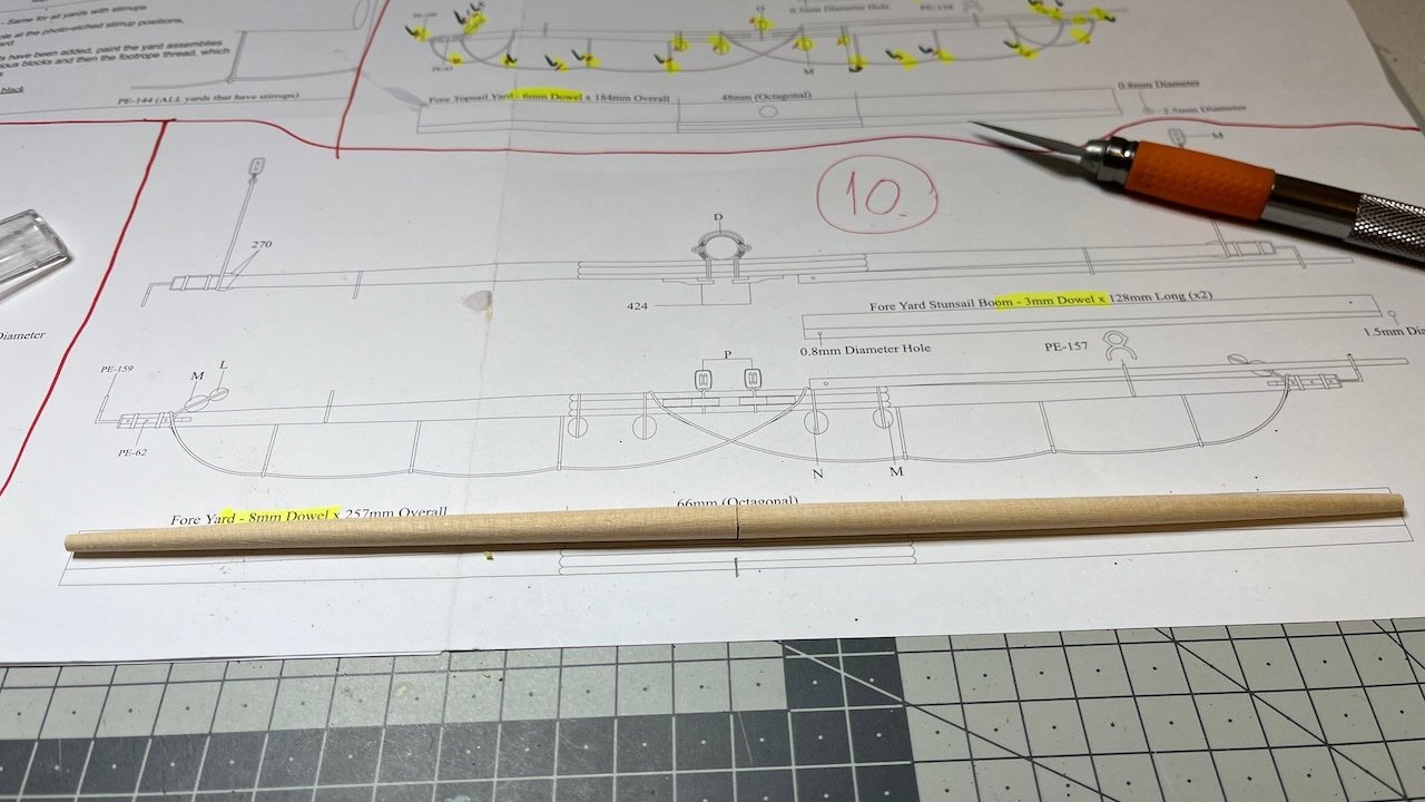
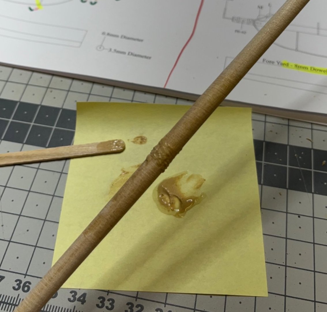
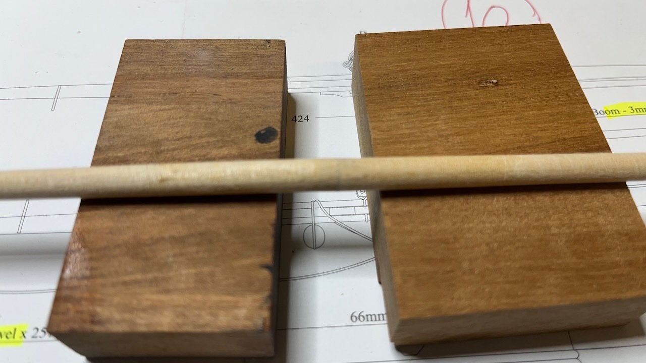
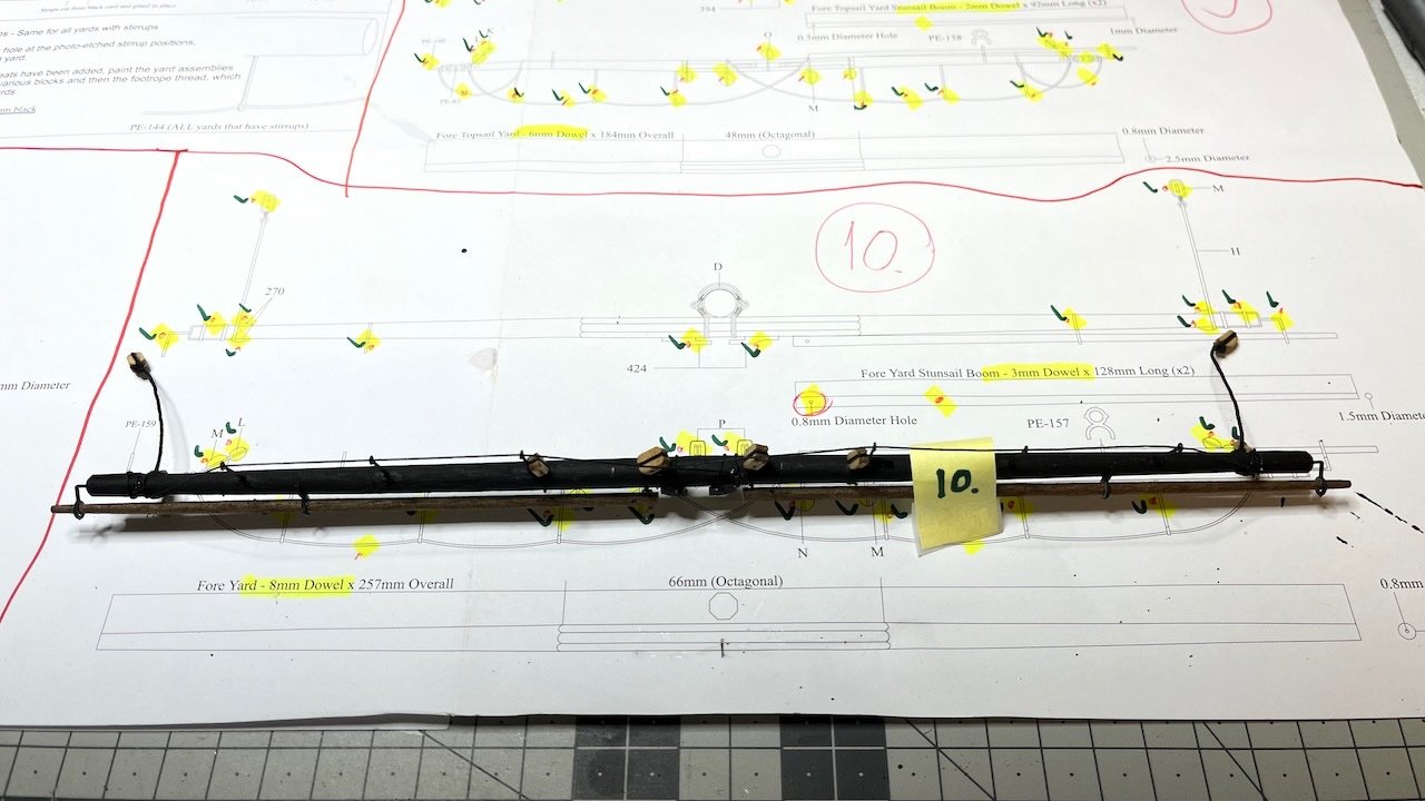
Build day 123: 4,5 hr / Total 268 hours Fore Yard, the last one of my yard construction. For tapering I followed a different approach at this one. I used two halves tapered on one side, the joint glued together using pin enforcement and wood fill. Partly out of curiosity, partly thinking it would be easier to make symmetrical tapers at both ends (you can put side by side and compare). Also the joint would not be visible since I paint the yard to black. Overall it seems to work. Photos 768-774: Here as usual the dents on the thicker edges are from the drill chuck: Complete.

- 426 replies
-
- 6
-
-
- Vanguard Models
- Sphinx
- (and 1 more)
-
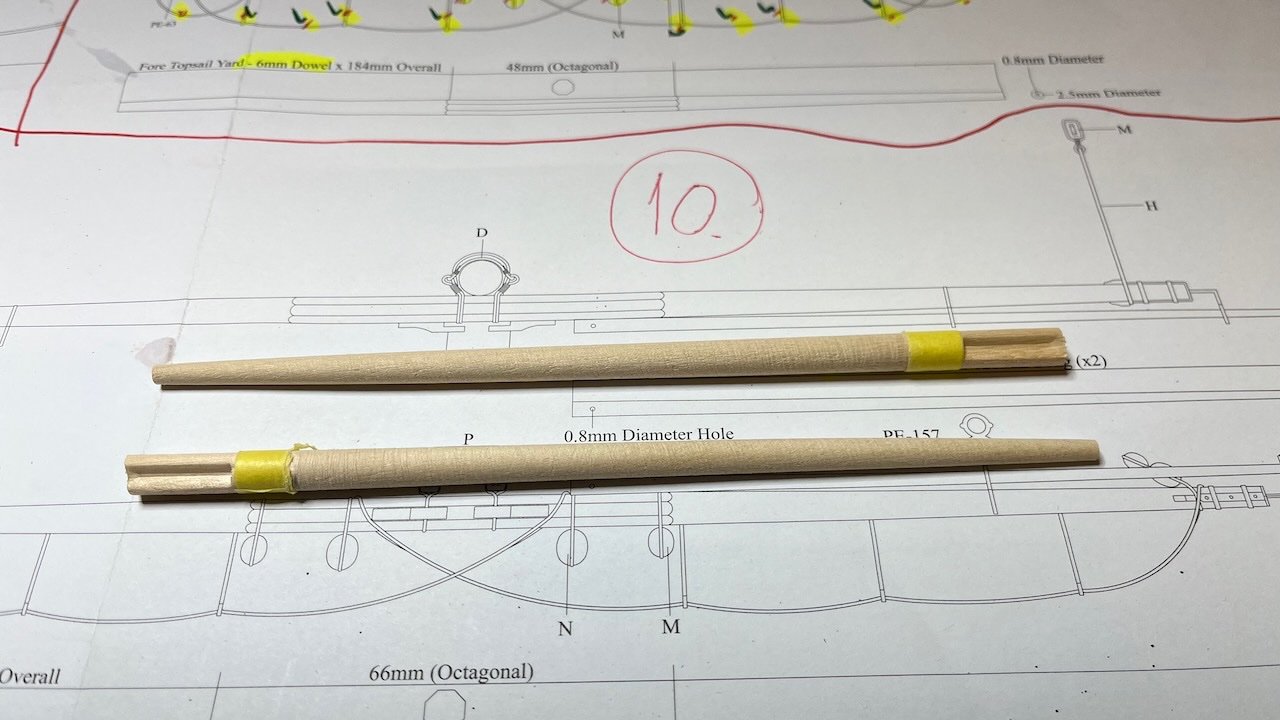
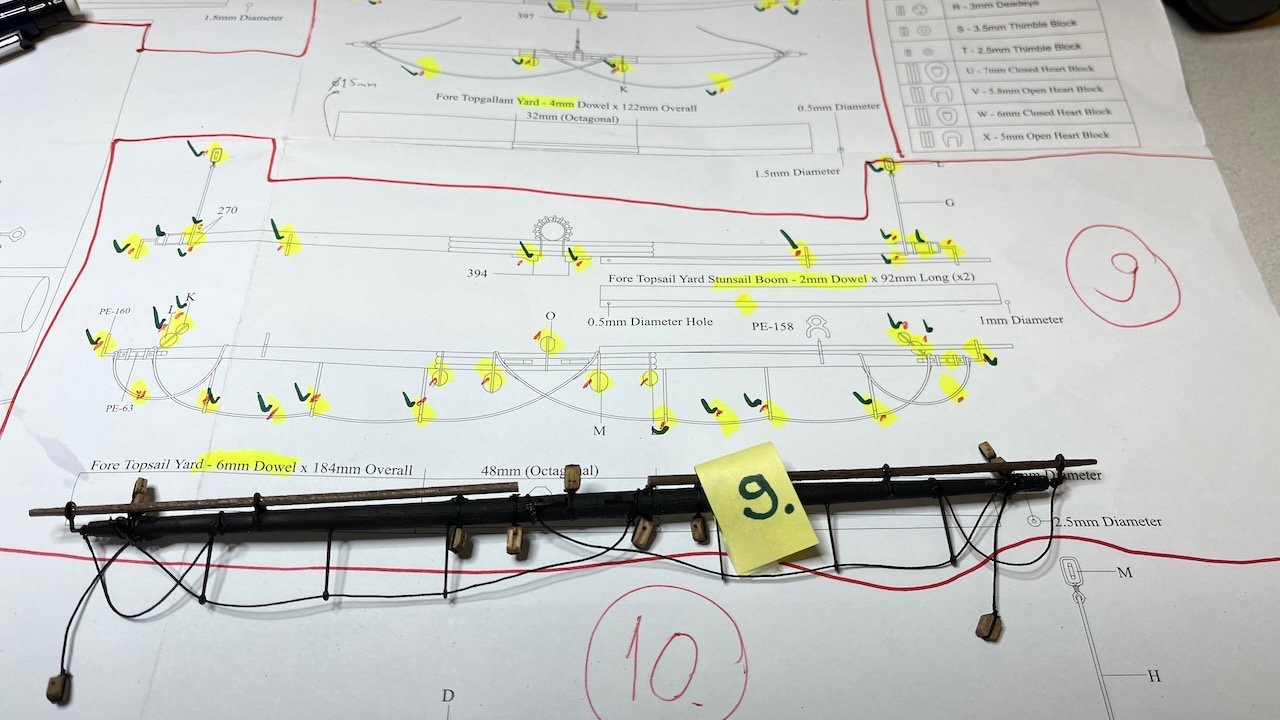
Build days 121-122: 2,5 hr / Total 263,5 hours Fore Topsail Yard. Similar process here with nothing too special to mention. Photo 767:
- 426 replies
-
- 5
-
-
- Vanguard Models
- Sphinx
- (and 1 more)
-
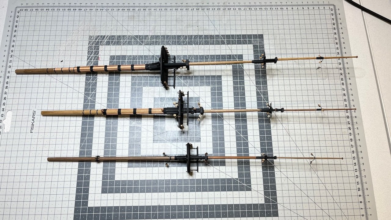
Build day 120: 5 hr / Total 261 hours Crossjack Yard, Fore Topgallant Yard and Main Topsail Yards ready. Below Fore Topgallant- and Main Topsail Yards. Photos 765-766:
- 426 replies
-
- 3
-
-
- Vanguard Models
- Sphinx
- (and 1 more)
-
Good point, Allan. Actually until now I never paid attention to the orientation of the holes. I even found it is easier to rig if the hole is actually further away from the mast or yard, making it easier to reach during rigging. Hmm. I am not sure if I modify those I have already done but definitely will check their position going forward. 👍 /Aydin
- 426 replies
-
- 3
-
-
- Vanguard Models
- Sphinx
- (and 1 more)
-
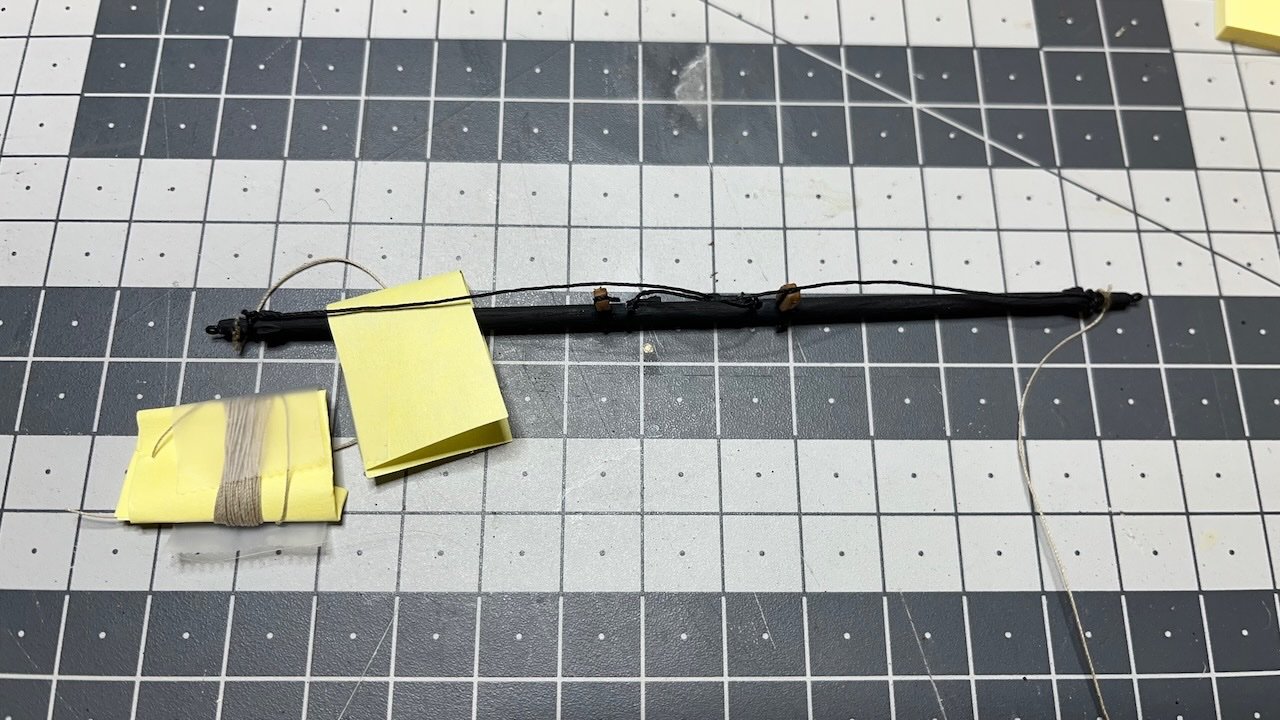
Build day 119 continued: 1 hr / Total 256 hours Photo 764: Main Topgallant Yard complete. 70cm long natural thread is attached on both ends. I wrapped them around a piece of paper and secured with a tape in order to keep them safe moving around.
- 426 replies
-
- 5
-
-
- Vanguard Models
- Sphinx
- (and 1 more)
-
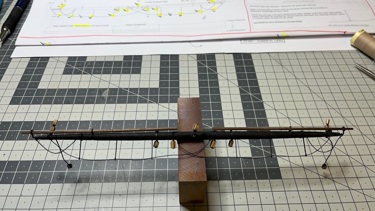
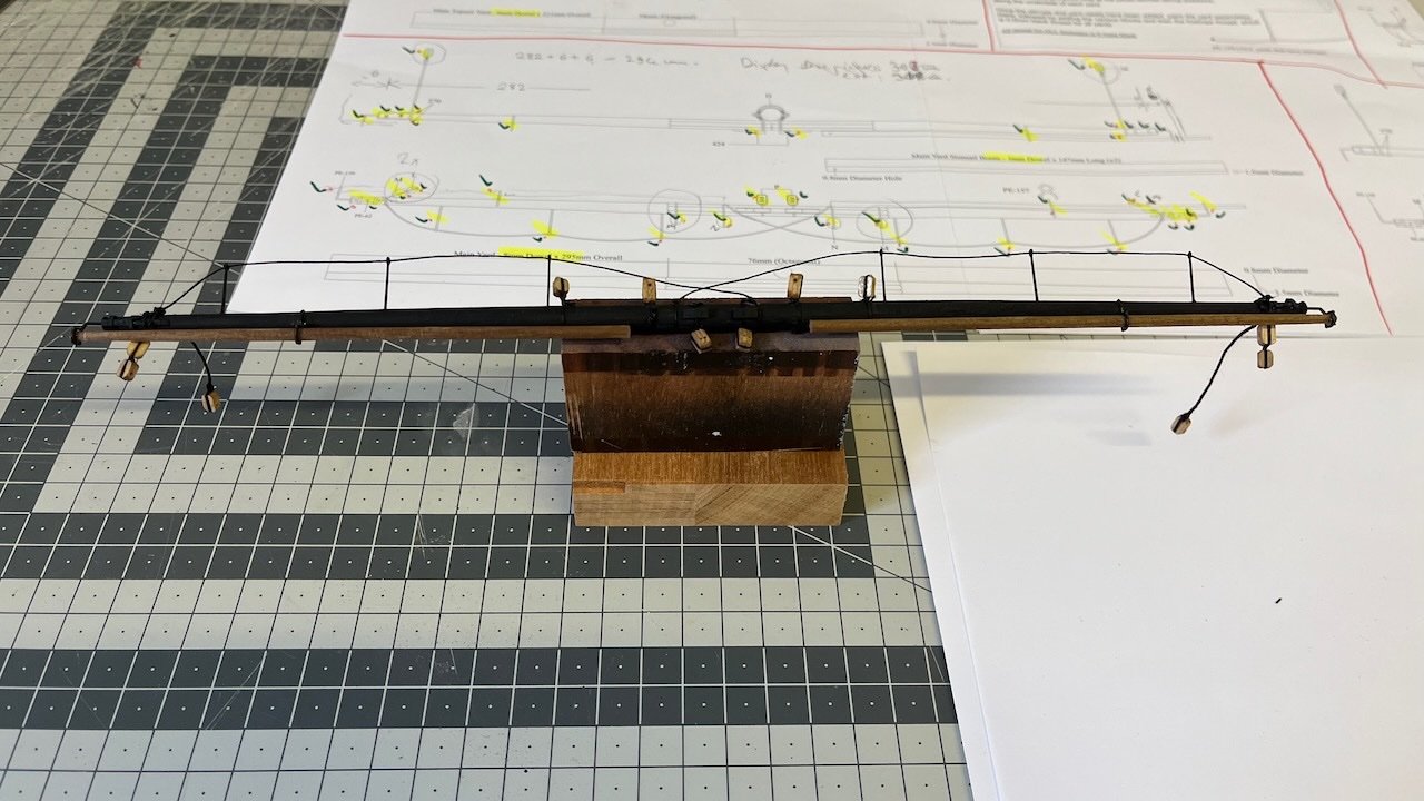
Build day 119: 2 hr / Total 255 hours Photo 763: Main Yard complete. It took altogether about 3 hours.
- 426 replies
-
- 4
-
-
- Vanguard Models
- Sphinx
- (and 1 more)
-
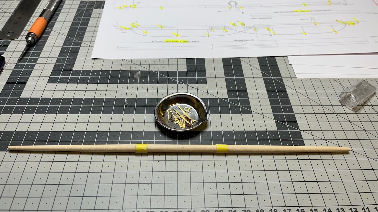
Build day 118: 1 hr / Total 253 hours Main yard. It normally uses 8 mm dowel to be tapered to 6mm in the middle and 3.5mm at the ends. I found a 6 mm dowel in my stock that saved me from most of the heavy work. It will be painted in black therefore the color does not matter I have to regretfully confess that the total length of my Main Yard will be 6 mm shorter than in the plan from both ends. The reason is that my display shelf is just damn 10 mm too narrow to fit the Sphinx. The Main Yard determines the width of the ship. Photo 762: Dowel tapered. All the metal and wooden fittings (except for the blocks) are in the metal cup.
- 426 replies
-
- 7
-
-
- Vanguard Models
- Sphinx
- (and 1 more)
-
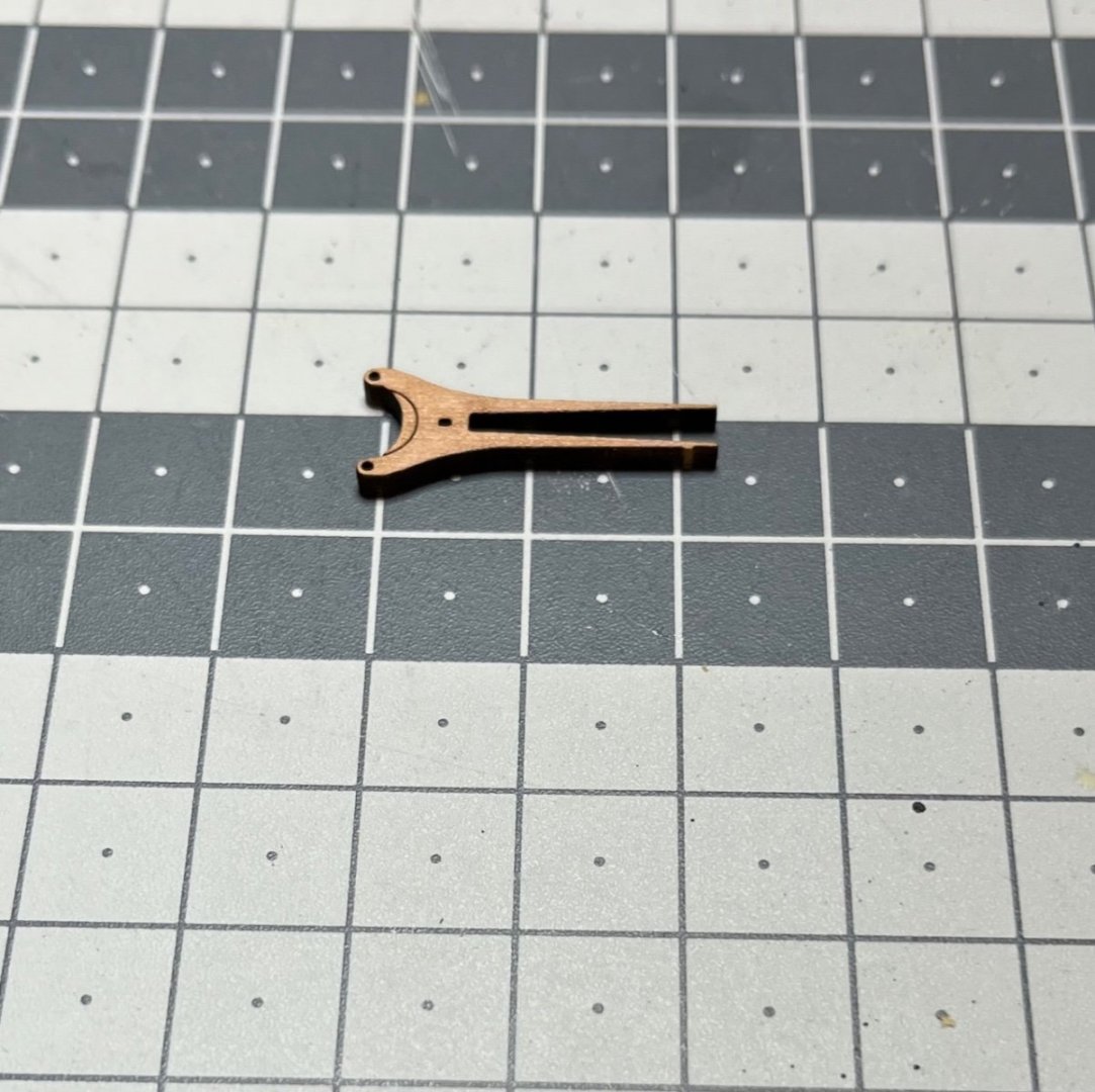
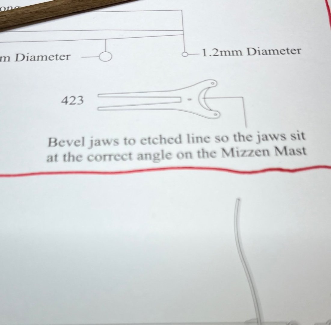
Build day 117: 1,5 hrs / Total 252 hours Mizzen Gaff. I don't know why I painted this one to black, too, like the yards, but anyway it is black now. Photos 759-761: Jaws needs to be bewelled to fit the Mizzen mast's angle. The guide line is provided. Nice detail.

- 426 replies
-
- 2
-
-
- Vanguard Models
- Sphinx
- (and 1 more)
-
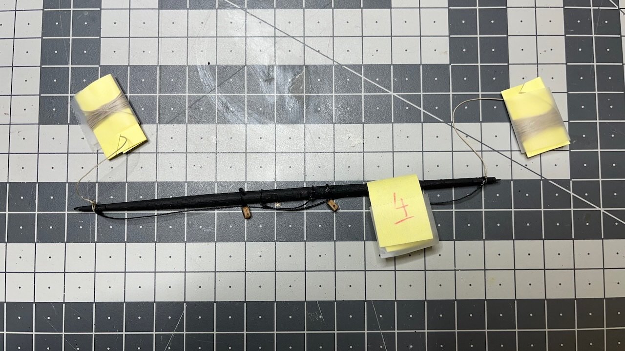
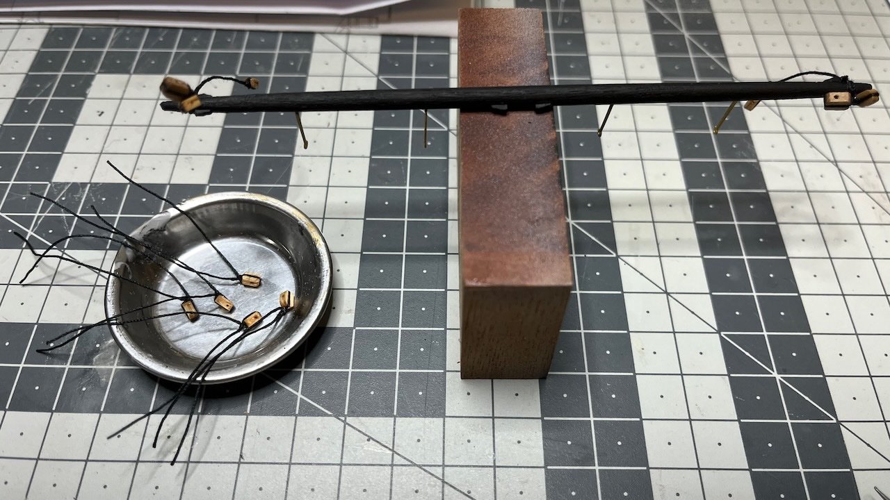
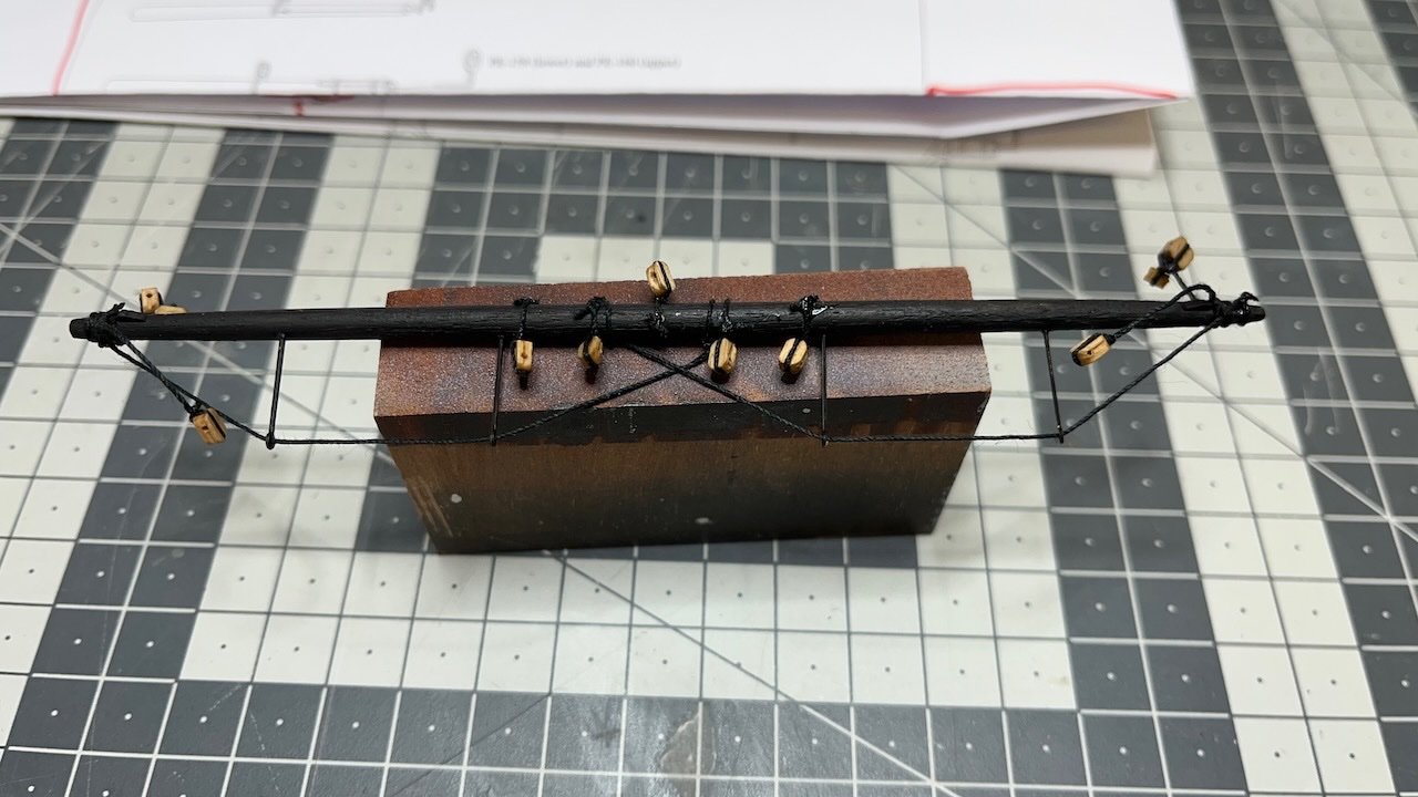
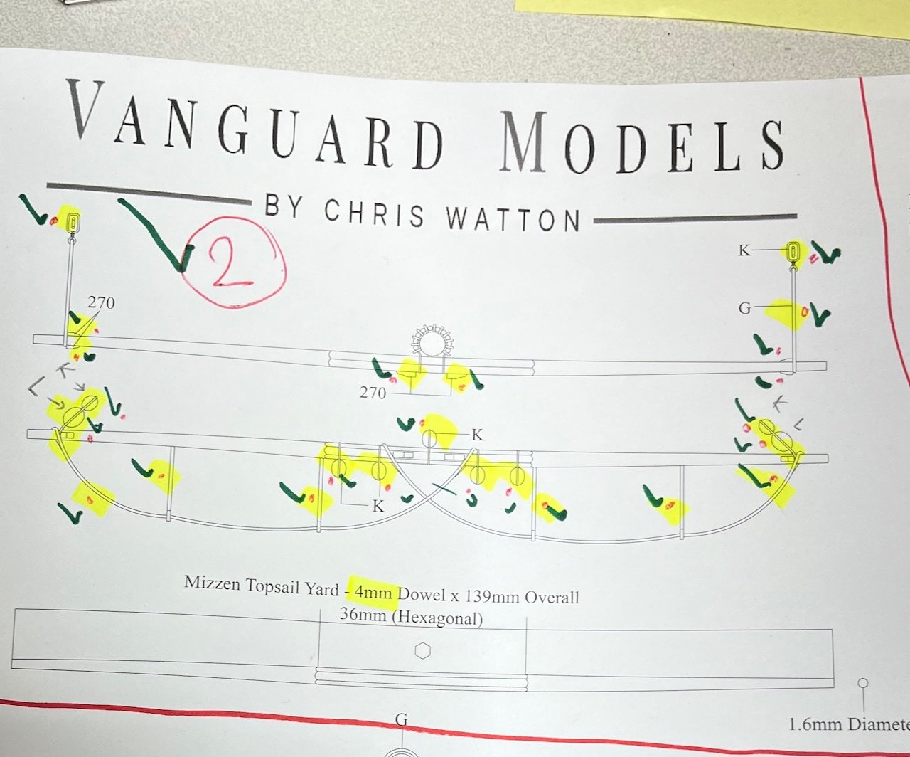
Build days 115-116: 3 hrs / Total 250,5 hours Mizzen Topsail Yard Photos 756-758. Here I mark on the plan the parts I have done with a green check so that I don't miss anything.
- 426 replies
-
- 3
-
-
- Vanguard Models
- Sphinx
- (and 1 more)