HOLIDAY DONATION DRIVE - SUPPORT MSW - DO YOUR PART TO KEEP THIS GREAT FORUM GOING! (83 donations so far out of 49,000 members - C'mon guys!)
×


aydingocer
-
Posts
916 -
Joined
-
Last visited
Content Type
Profiles
Forums
Gallery
Events
Everything posted by aydingocer
-
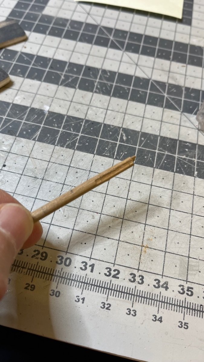
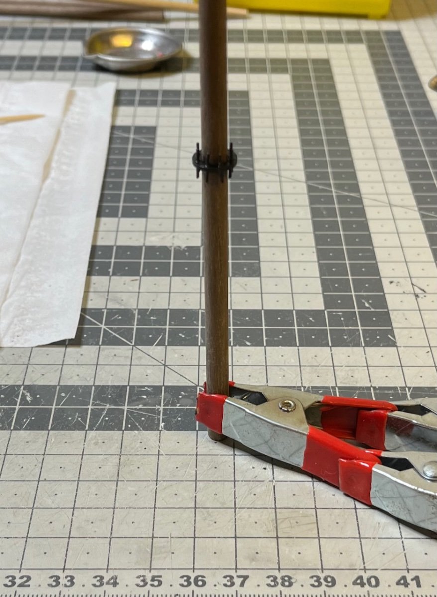
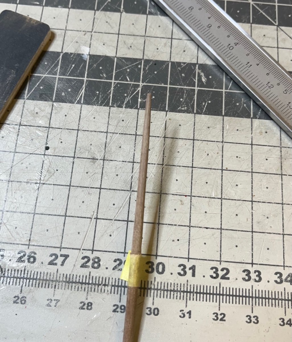
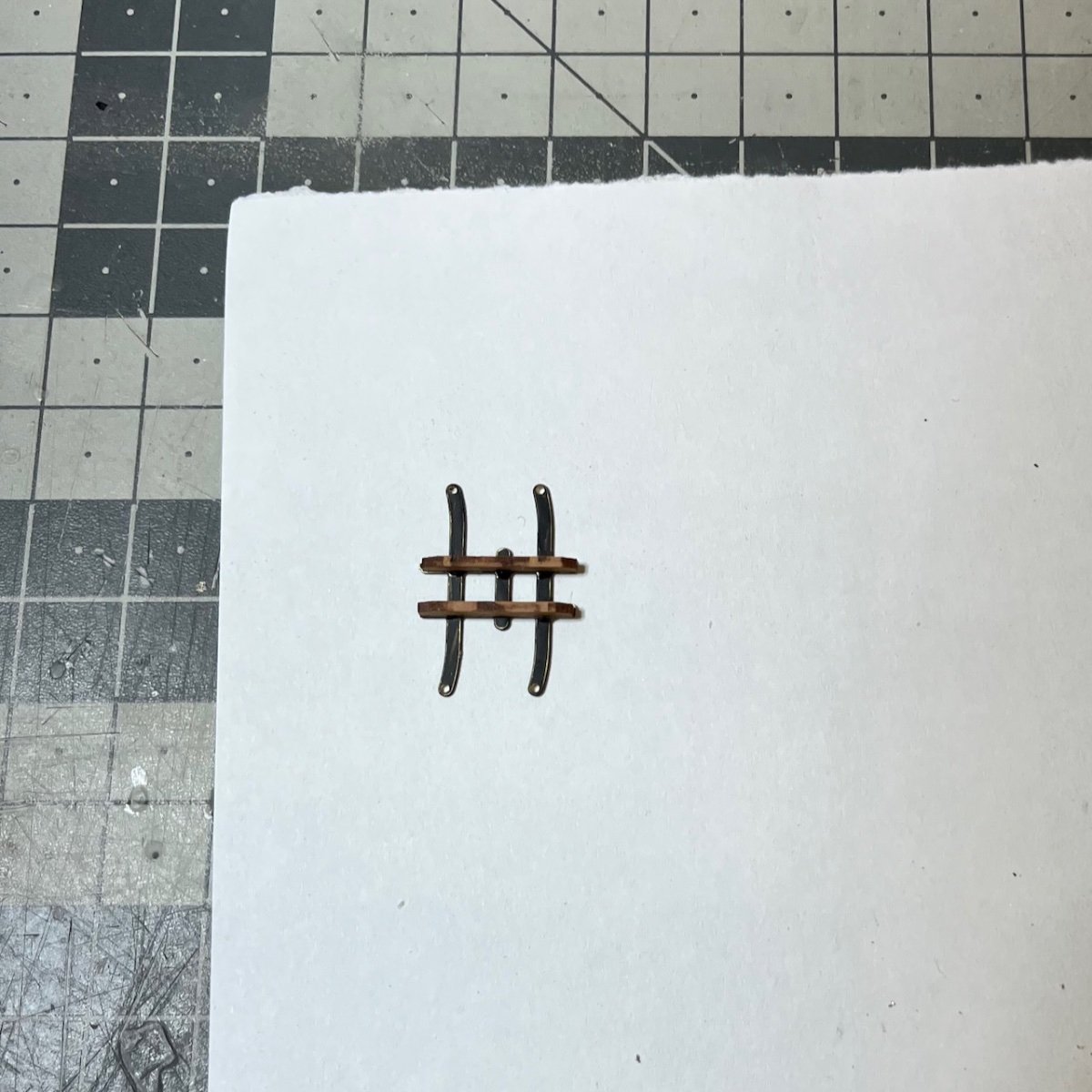
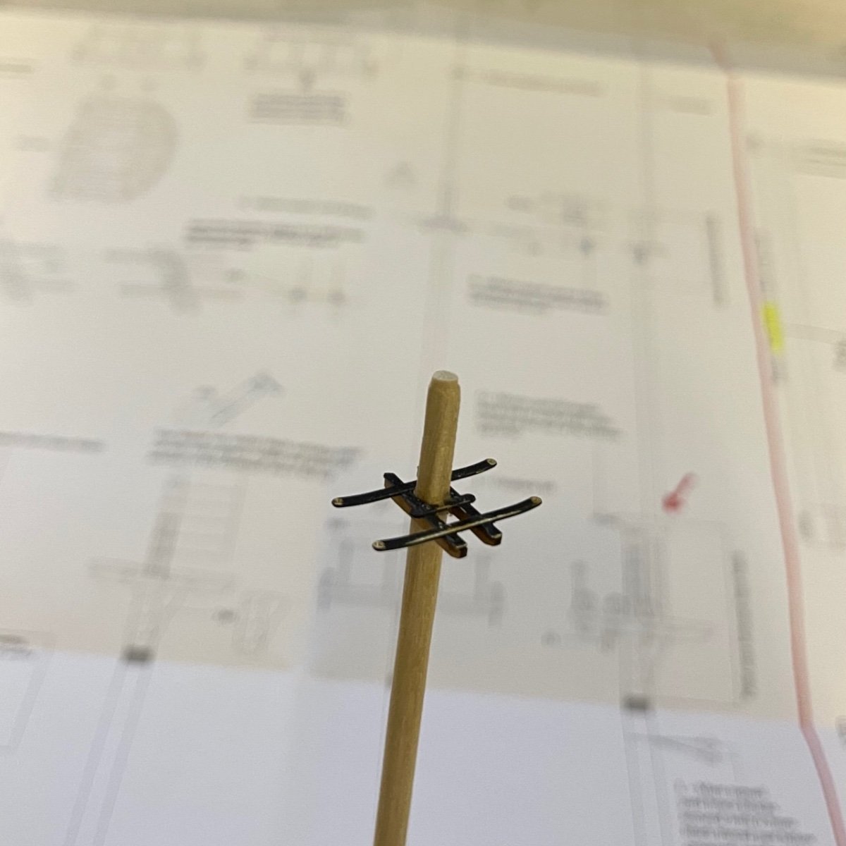
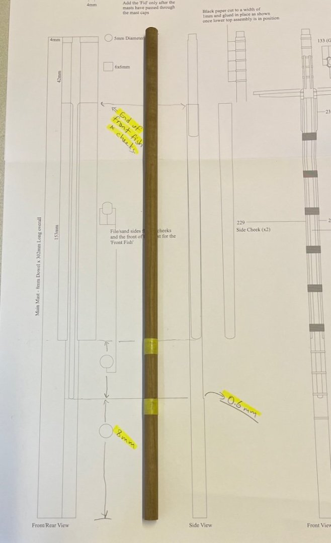
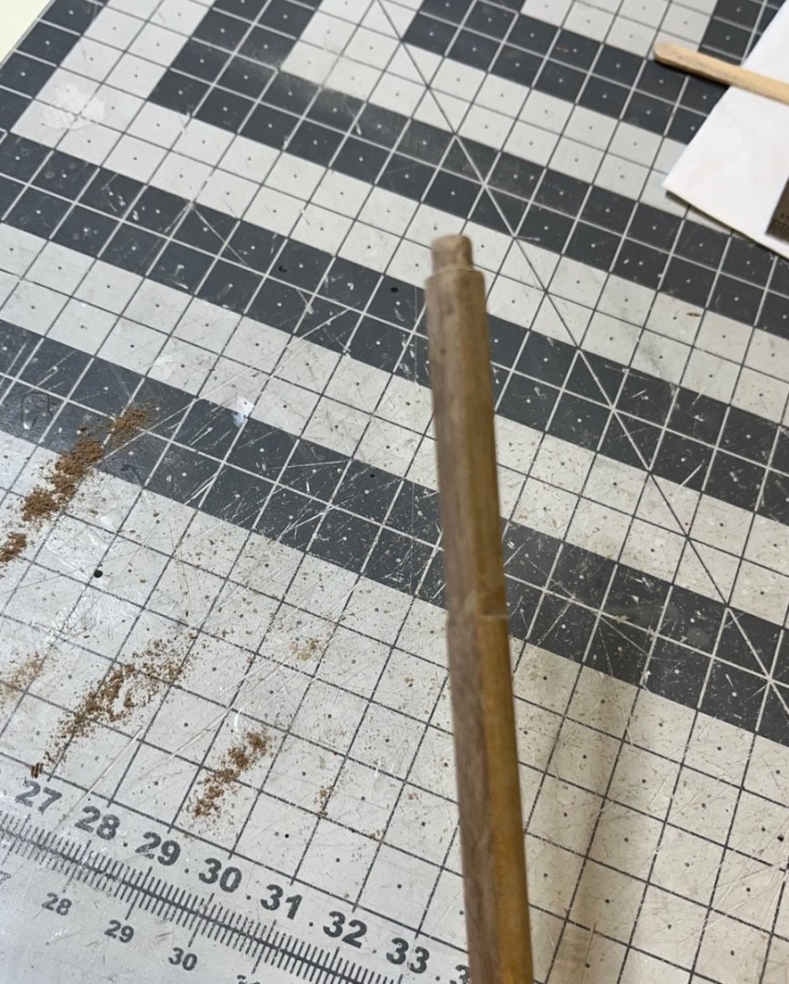
 Build days 99-101: 5 hrs / Total 219.5 hours Foremast Part 1, took altogether 5 hours in 3 separate days. Some photos showing the progress. Also with this post I am leaving 100 build days behind! With 220 hours of work, it is around an average of 2hrs per build day. Photos 706-711

- 426 replies
-
- 3
-

-
- Vanguard Models
- Sphinx
- (and 1 more)
-
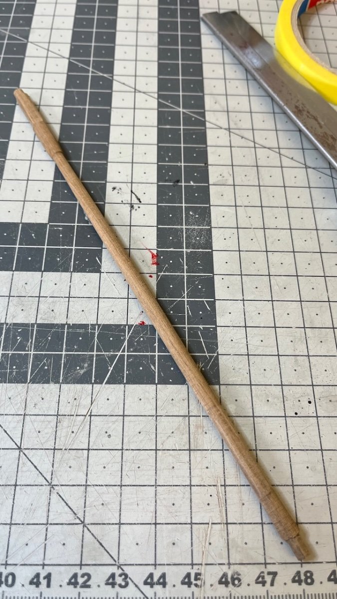
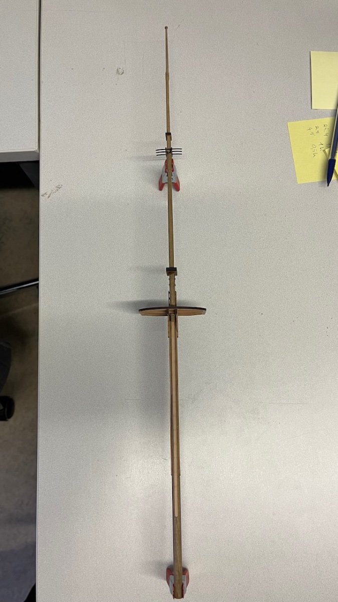
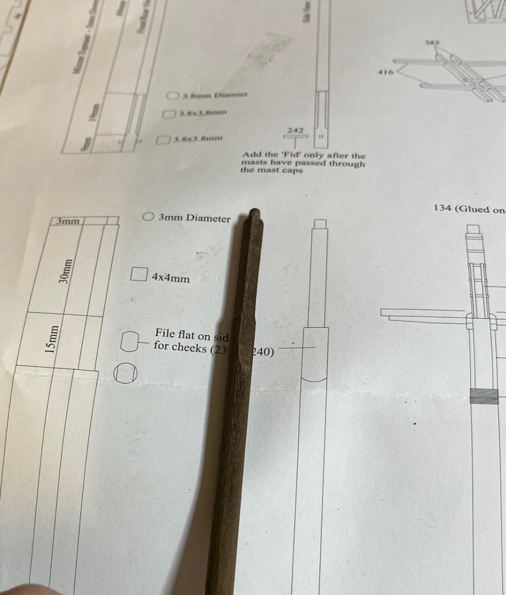
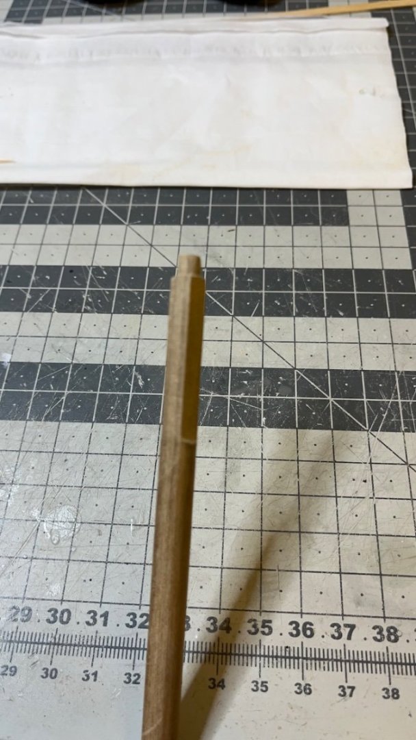
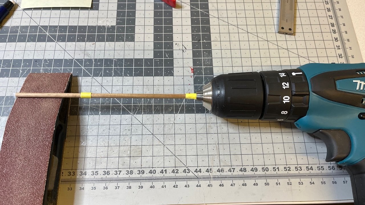
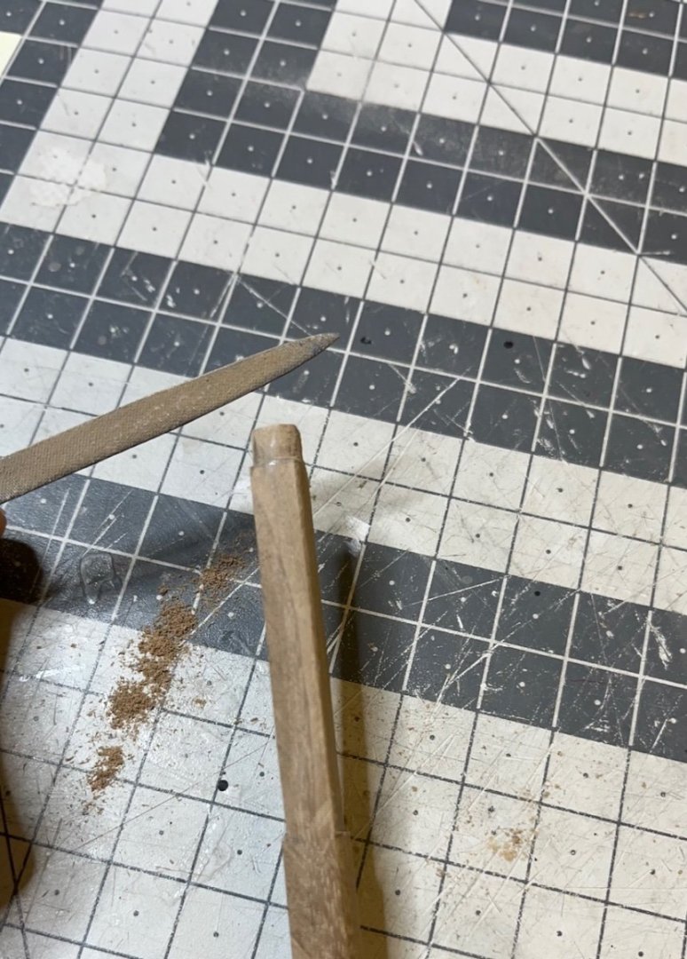
Build days 94-98: 8.5 hrs / Total 214.5 hours After a total of 8.5 hours of work spread to 5 days, main mast Part 1 is ready. As I indicated before, by "Part 1" I mean leaving the details (eyelets, blocks, cord wraps etc) for later to do together with all three masts, in accordance with the instructions. I have already posted some of the work in the post above. Here are some of the remaining photos: Photos 700-705 This is how the drill chuck squeezes the dowel. Needless to say, you cut the dowel in excess enough length to accommodate for inserting the drill machine chuck: That's all for now. Thanks for watching!


- 426 replies
-
- 4
-
-
- Vanguard Models
- Sphinx
- (and 1 more)
-
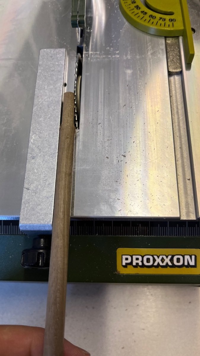
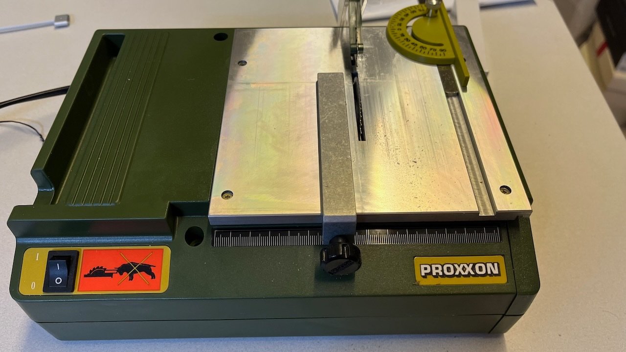
Yes this Proxxon is quite precise compared to its bulky look.
- 426 replies
-
- 2
-
-
- Vanguard Models
- Sphinx
- (and 1 more)
-
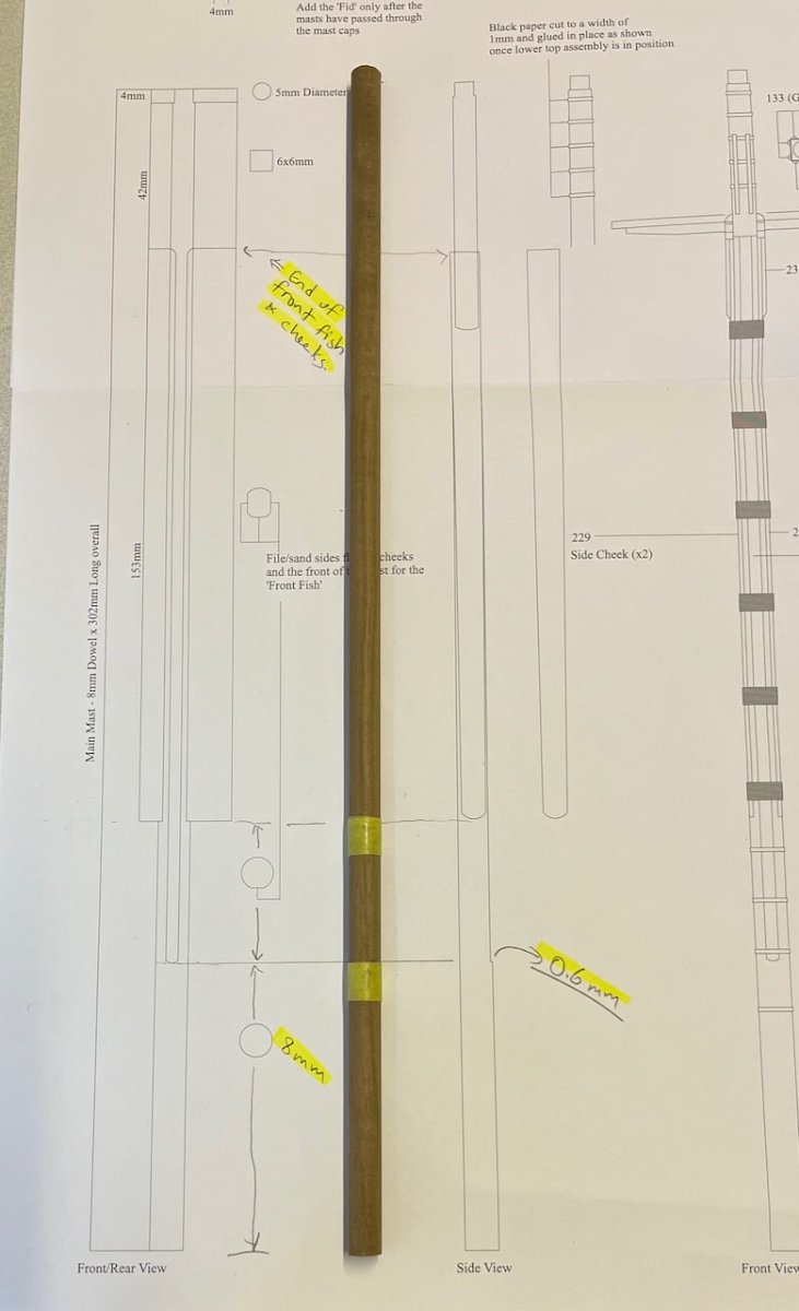
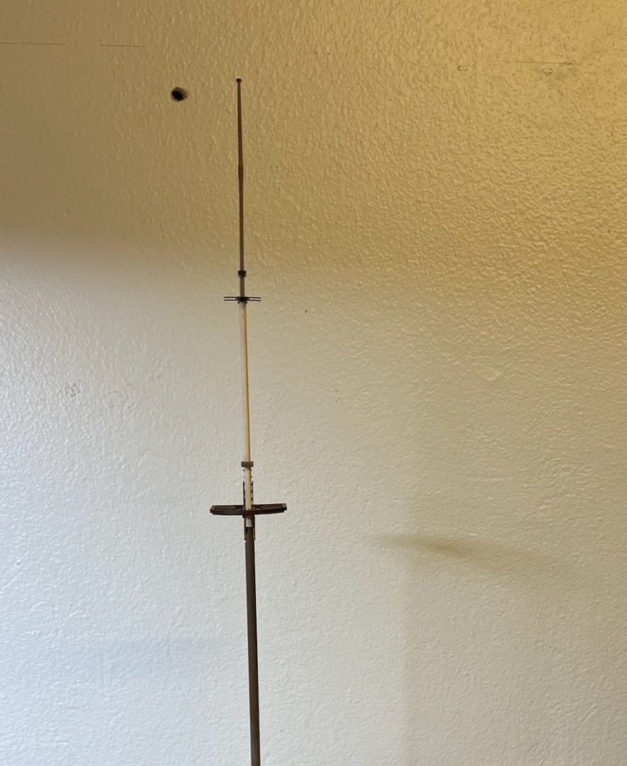
Quick update: I am now continuing with Main Mast. Main mast goes several shapes from bottom up, as you see in the plan. I realized I could try my Proxxon Bench Circular Saw (Model KS 230), which has been sitting on the shelf for a long time I even forgot I have it. It worked well. Here I wanted to post some photos showing how it worked. Photos 693-699:


- 426 replies
-
- 9
-
-
- Vanguard Models
- Sphinx
- (and 1 more)
-
Photo 692: Mizzen mast Part 1 ready. That's all for now. Thanks for watching!
- 426 replies
-
- 3
-
-
- Vanguard Models
- Sphinx
- (and 1 more)
-
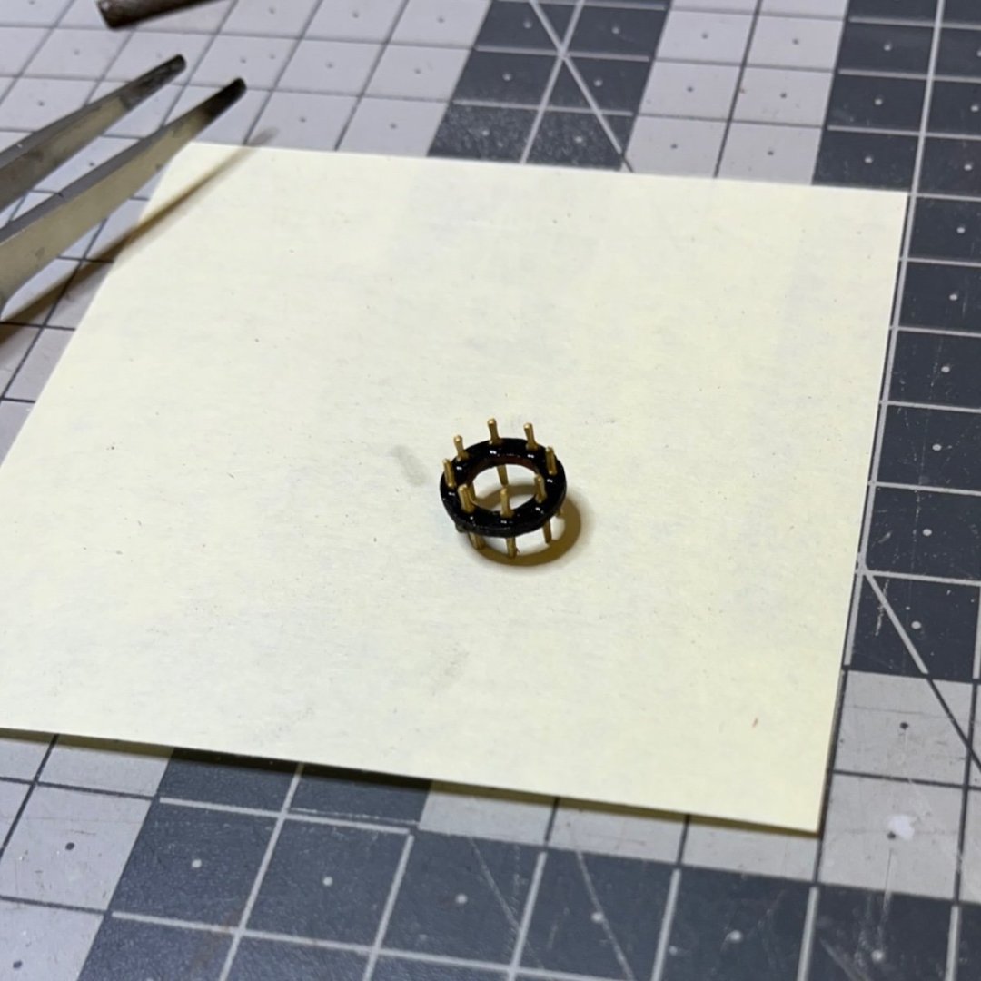
Photos 690-691: Mizzen Belaying Pin Ring and belaying pins. I painted them first and then glued in position on the mast.
- 426 replies
-
- 2
-
-
- Vanguard Models
- Sphinx
- (and 1 more)
-
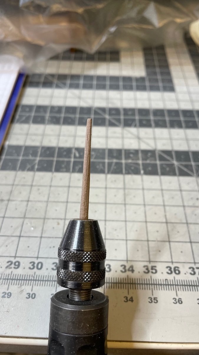
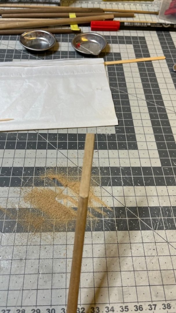
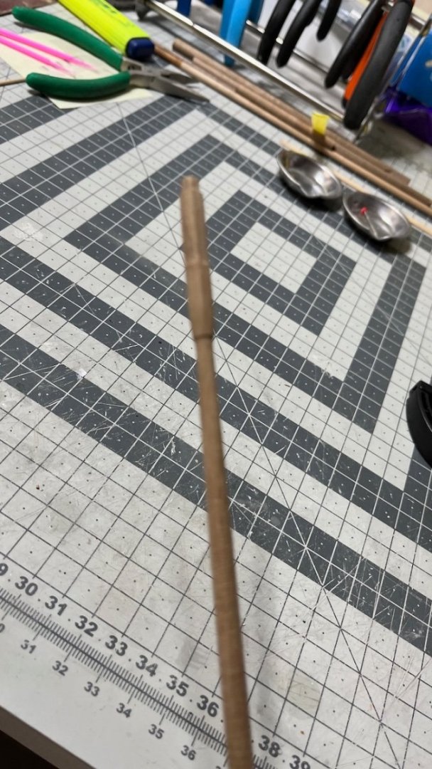
Photo 689: A picture showing the Mizzen Topgallant Mast progress. Also here I used my Proxxon handheld rotary tool for turning it to taper it with sandpaper.

- 426 replies
-
- 2
-
-
- Vanguard Models
- Sphinx
- (and 1 more)
-
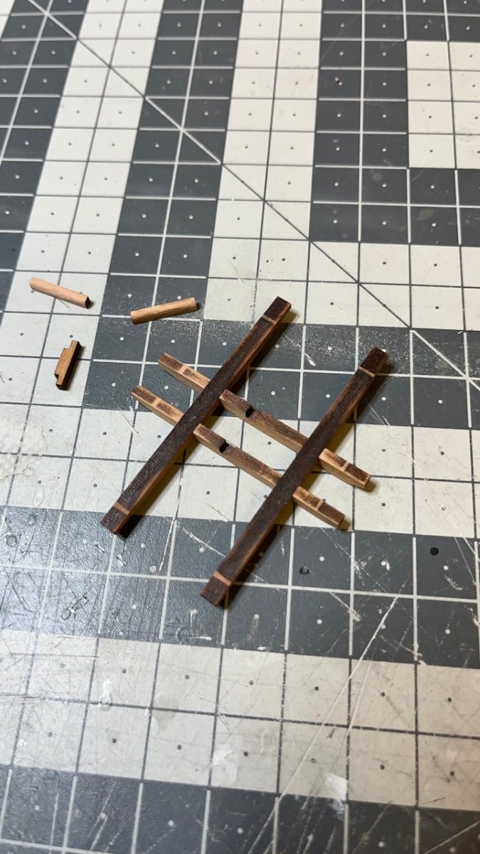
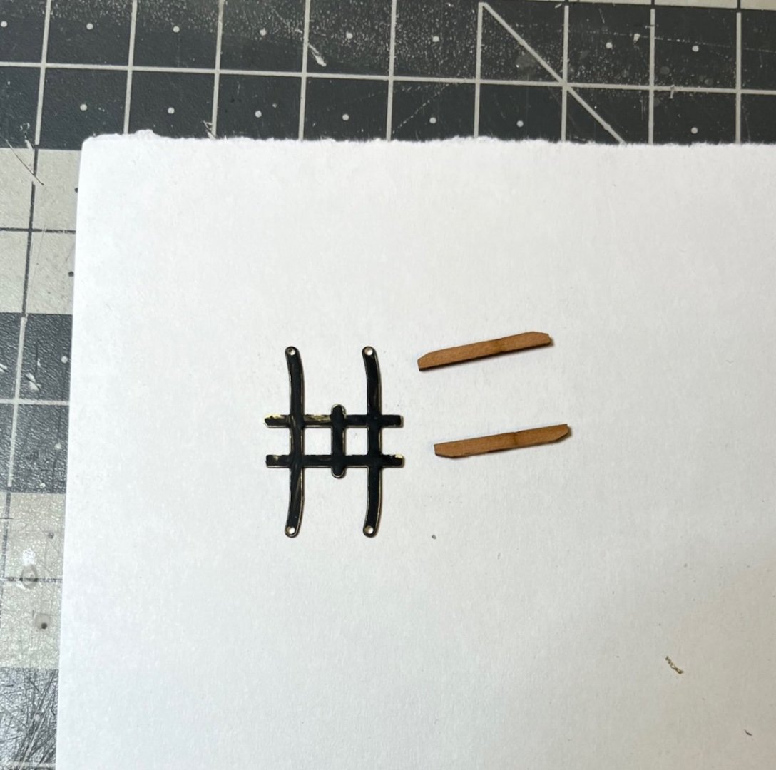
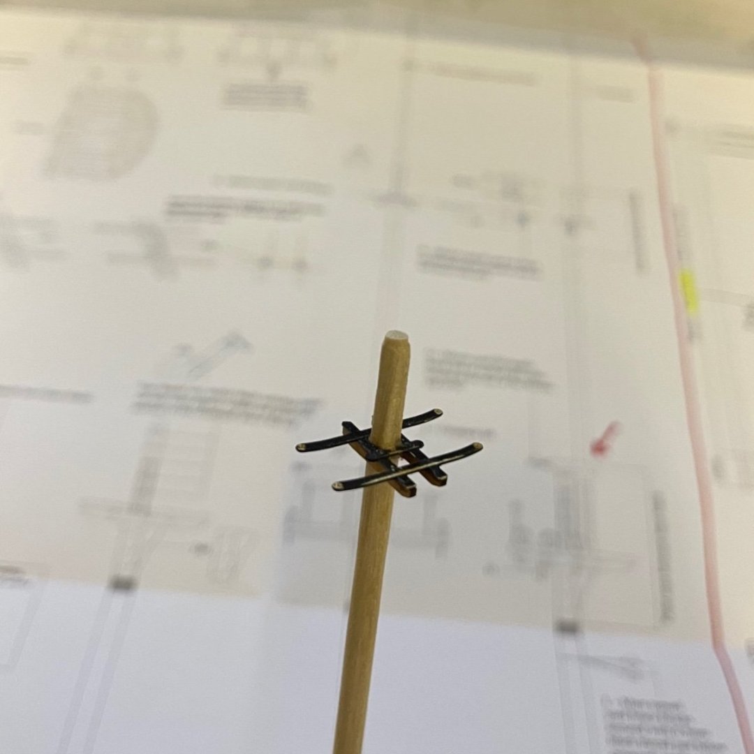
Build days 90-93: 4,5 hrs / Total 206 hours Continued with the Mizzen mast with 4,5 hours of work spread into 4 days, concluding what I call "Part 1". This means leaving the details (eyelets, blocks, cord wraps etc) for later to do together with all three masts, in accordance with the instructions. Photos 686-688: Mizzen topmast cross tree construction. Black part in the picture is from the photo etched sheet.

- 426 replies
-
- 2
-
-
- Vanguard Models
- Sphinx
- (and 1 more)
-
Thanks for very useful tips. I have actually managed this section now but I will definitely refer to these tips in the coming steps. There are still several similar tasks ahead with the masts.
- 426 replies
-
- 3
-
-
- Vanguard Models
- Sphinx
- (and 1 more)
-
No, it simply would risk more visible harm than using a slightly thinner diameter, though not impossible. Anyway I am proceeding already with the option.
- 426 replies
-
- 2
-
-
- Vanguard Models
- Sphinx
- (and 1 more)
-
The platform below blocks it to some extent, you'd still need to sand the mast. Also towards the top of the mast there is a thickness of 4.5mm which is thicker than the hole (4mm). Therefore I guess right now the best move is to sand the lower part of the mast until it slides through the cap hole.
- 426 replies
-
- 1
-
-
- Vanguard Models
- Sphinx
- (and 1 more)
-
Thanks for the advice. I think in this case I will sand the lower part to thinner than 3.8x3.8 mm, maybe 3.2 x3.2 or something and slightly enlarge the mast cap hole also if I need to.
- 426 replies
-
- 2
-
-

-
- Vanguard Models
- Sphinx
- (and 1 more)
-
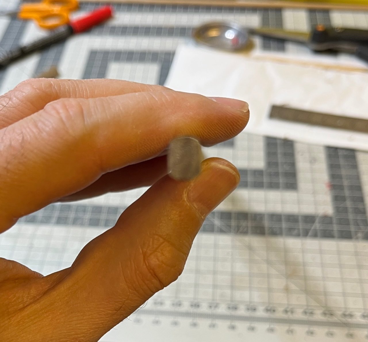
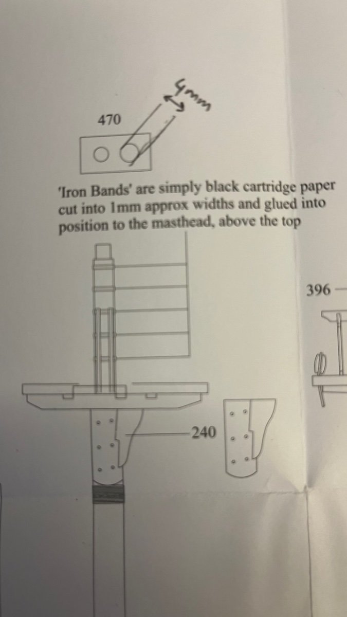
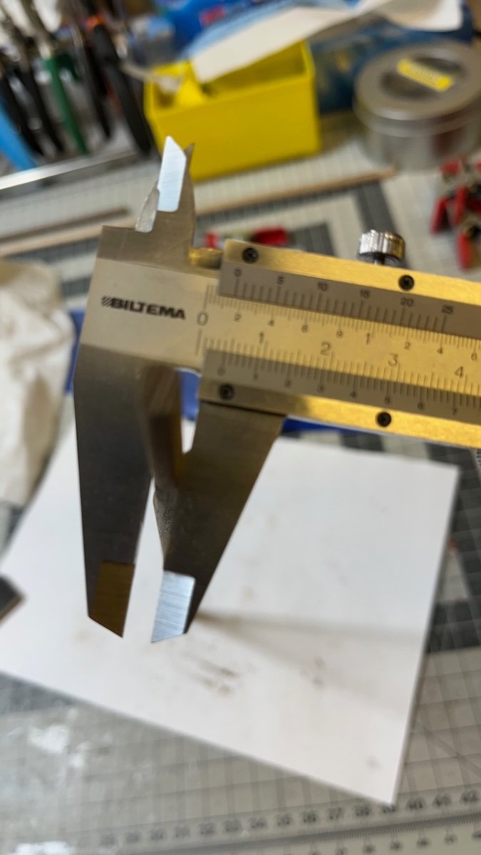
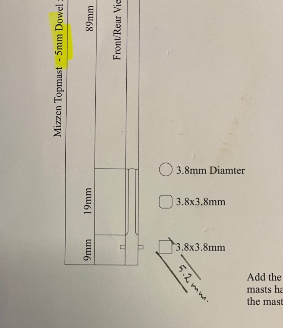
Hi Chris, The hole in the mast cap is too small to push the topmast and that's my issue. Mast cap hole is 4mm diameter while the topmast I need to push it through has a 5,2mm diagonal thickness, when I sand it to a 3.8m x 3.8mm square.
- 426 replies
-
- 1
-
-
- Vanguard Models
- Sphinx
- (and 1 more)
-
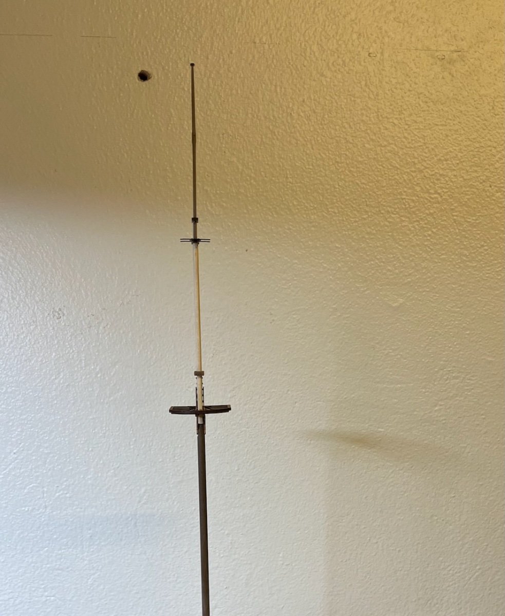
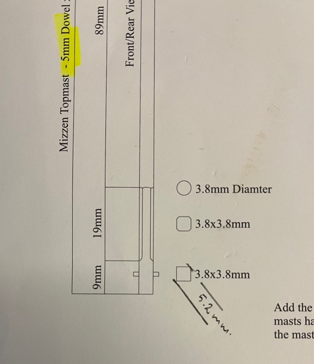
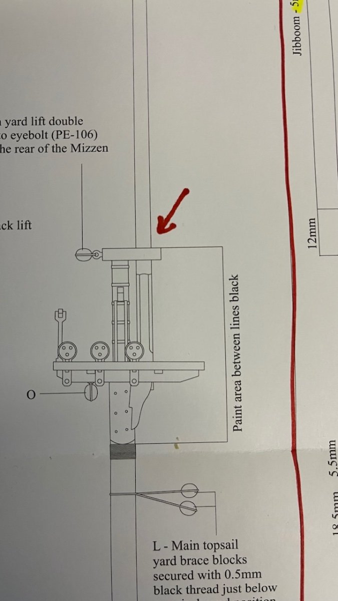
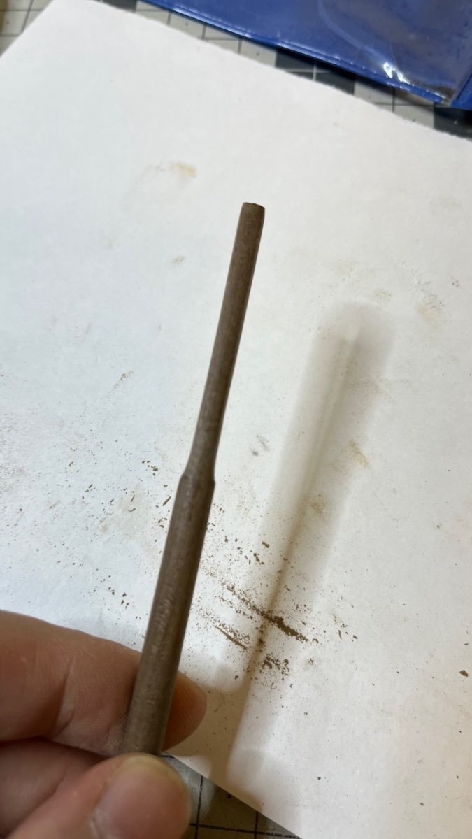
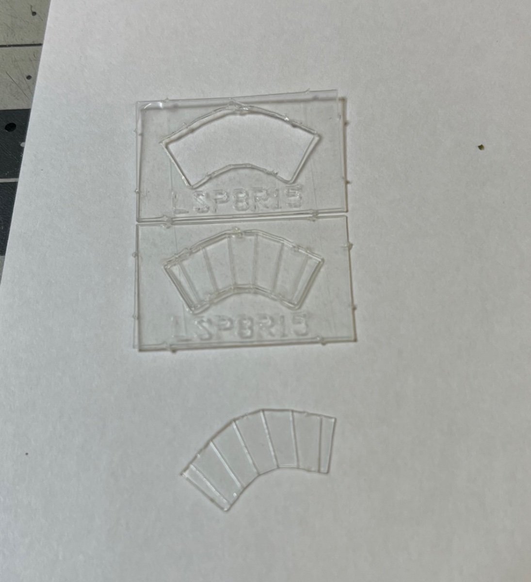
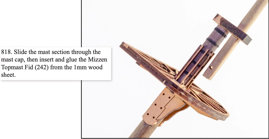
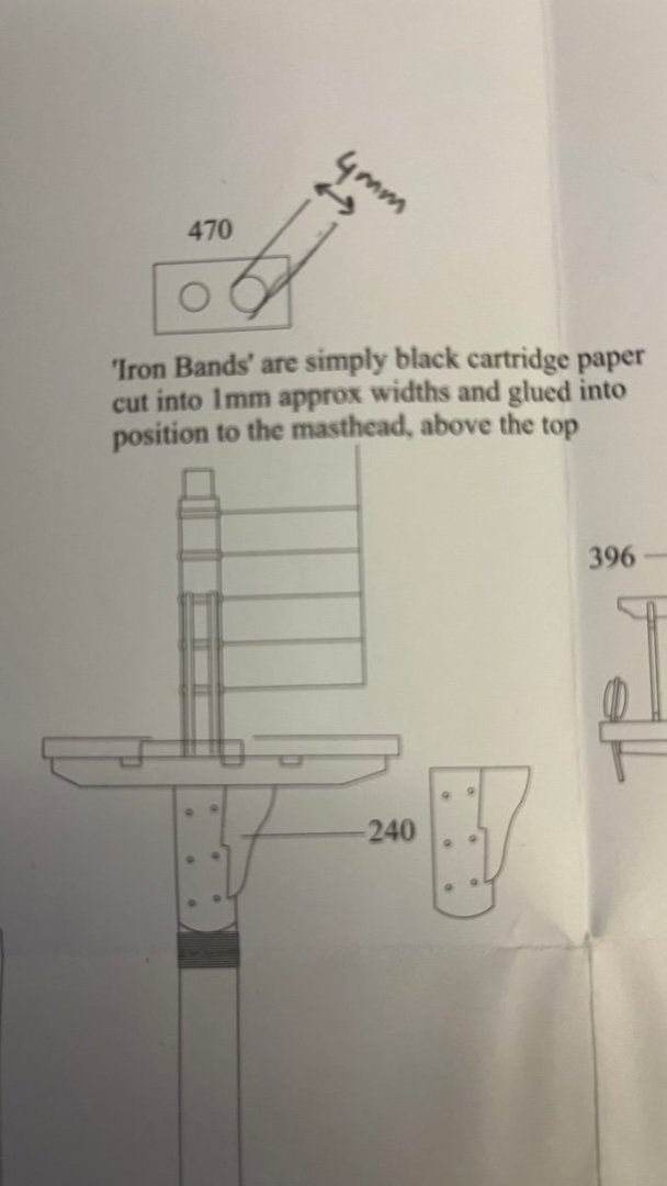
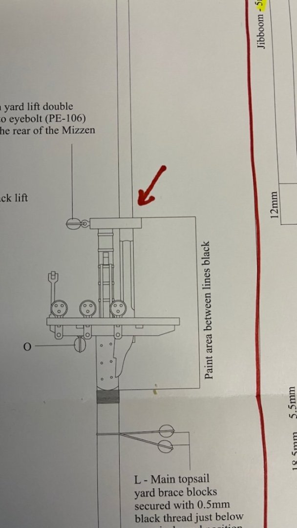
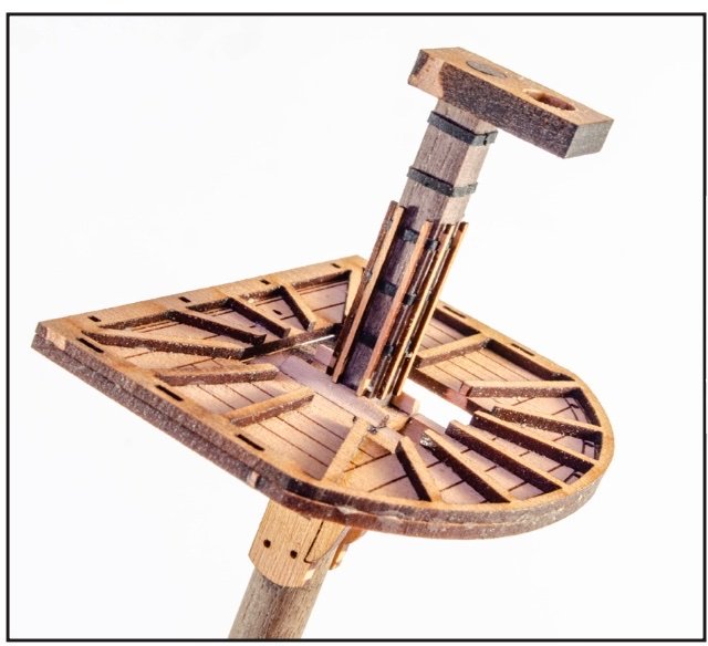
Now I have a problem. I appreciate any assistance: I am building the Mizzen mast and at this stage I am supposed to slide the Mizzen Topmast through the Mizzen Mast Cap as in this instruction. Photo 681: I already glued the cap in the previous step and it looks like this now (photo from the instruction manual): Photo 682: Photos 683-684: However it doesn't seem possible to slide it, as the lowest part of the topmast has a diagonal width of 5,2mm (or even 5,4mm if you calculate it mathematically), while the cap (part 470) is only 4mm in diameter. Photo 685: This is how it is supposed to look like afterwards: What am I supposed to do? If I enlarge the cap hole diameter to 5.2mm then I worry that it will look ugly since it will be only a 3,8mm diameter rod passing through it. The options I see are: - Cut the mast from where it will be inside the cap and install it in two pieces, or - Make the lower part also a round 3,8mm diameter and slide it in like that, in this case it will be a deviation from the original All advices welcome.
- 426 replies
-
- 1
-
-
- Vanguard Models
- Sphinx
- (and 1 more)
-
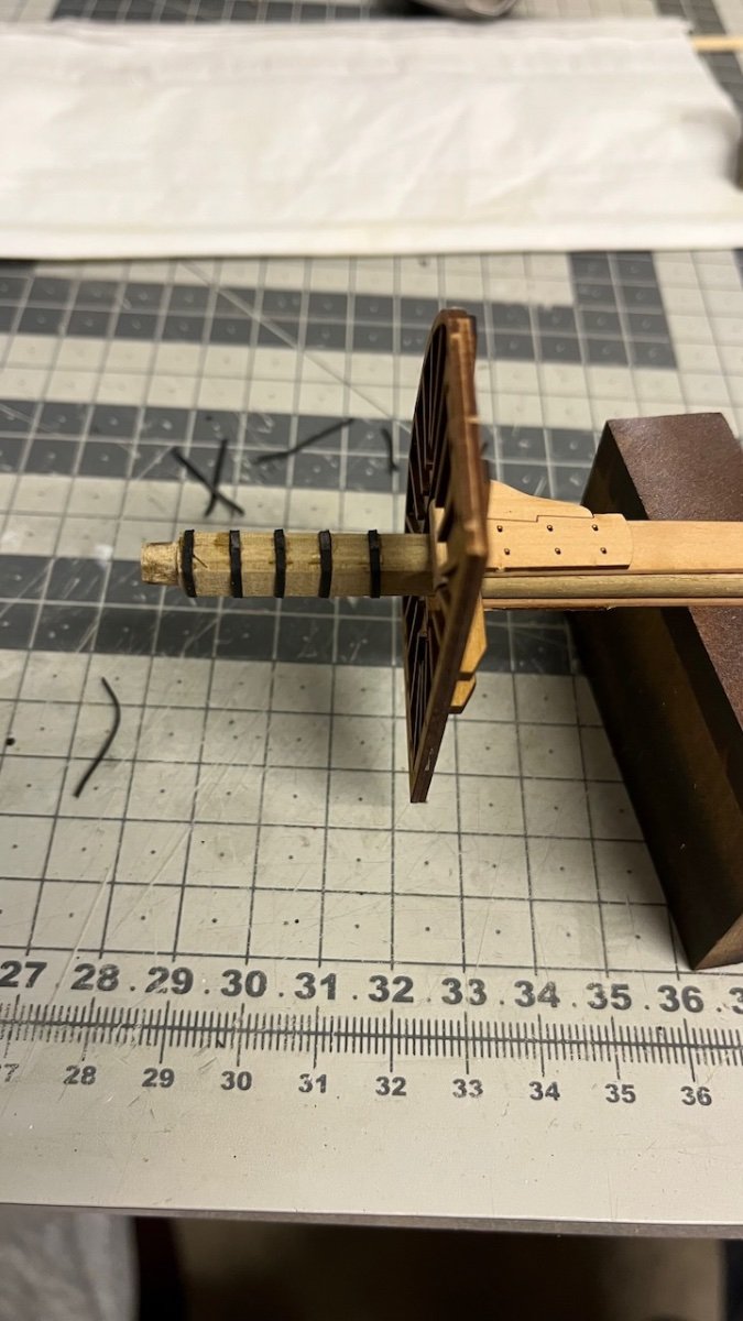
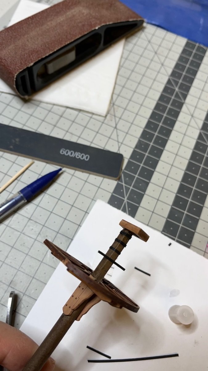
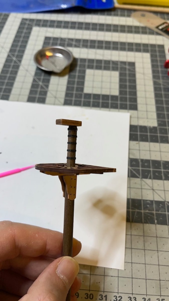
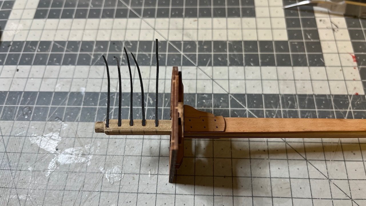
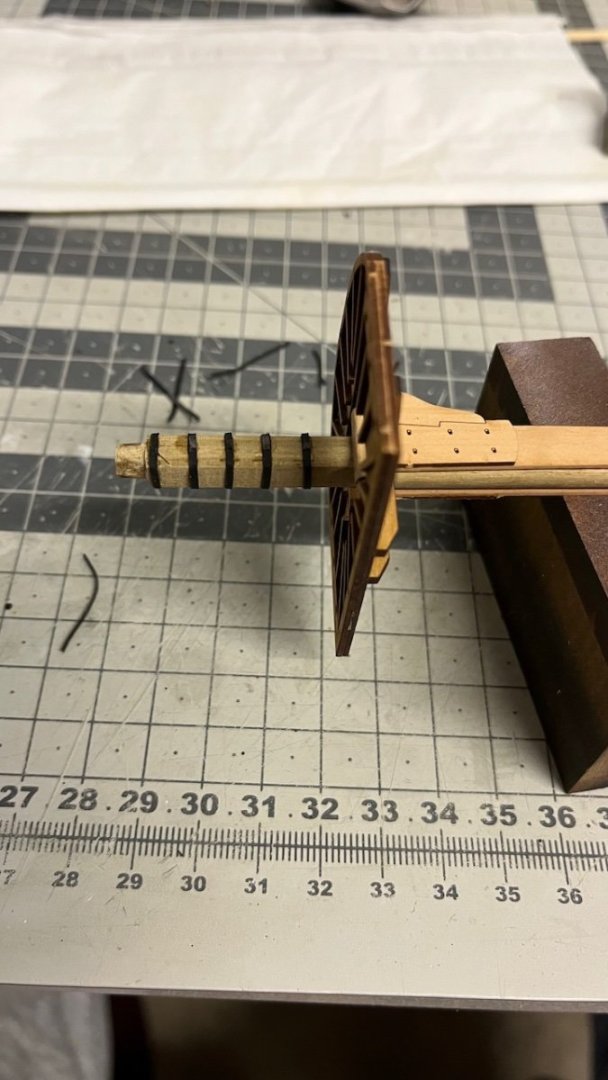
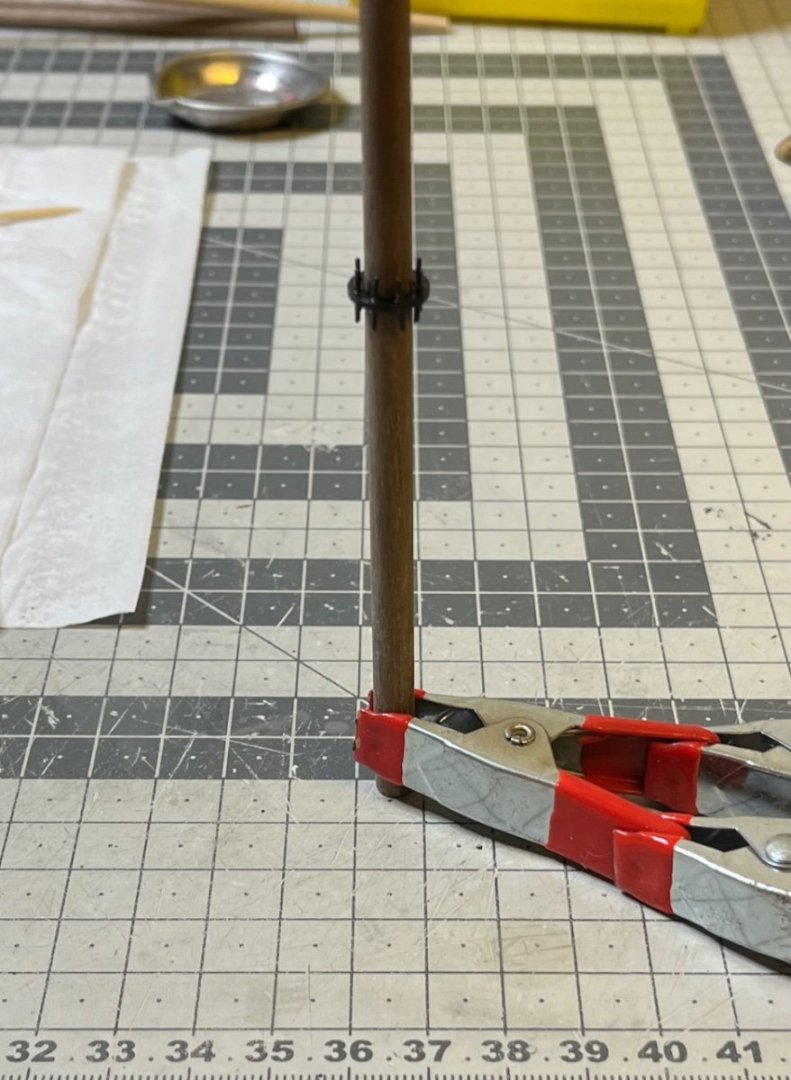
Photos 676-680: Iron bands (made of black paper sliced in 1 mm width) and mizzen mast battens. For correct positioning I carried the measure from the plan using an invisible tape. I used CA to glue them on the mast. At this point I am not worried about any discoloration caused by the glue nor about the laser char around the edges as this section will be eventually painted in black. That's all for now. Thanks for watching!


- 426 replies
-
- 13
-
-
- Vanguard Models
- Sphinx
- (and 1 more)
-
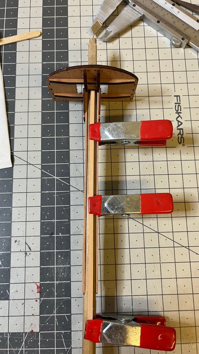
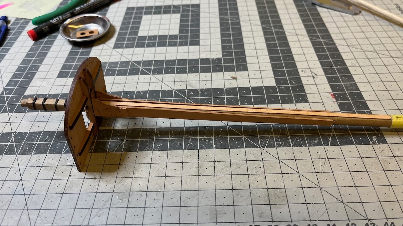
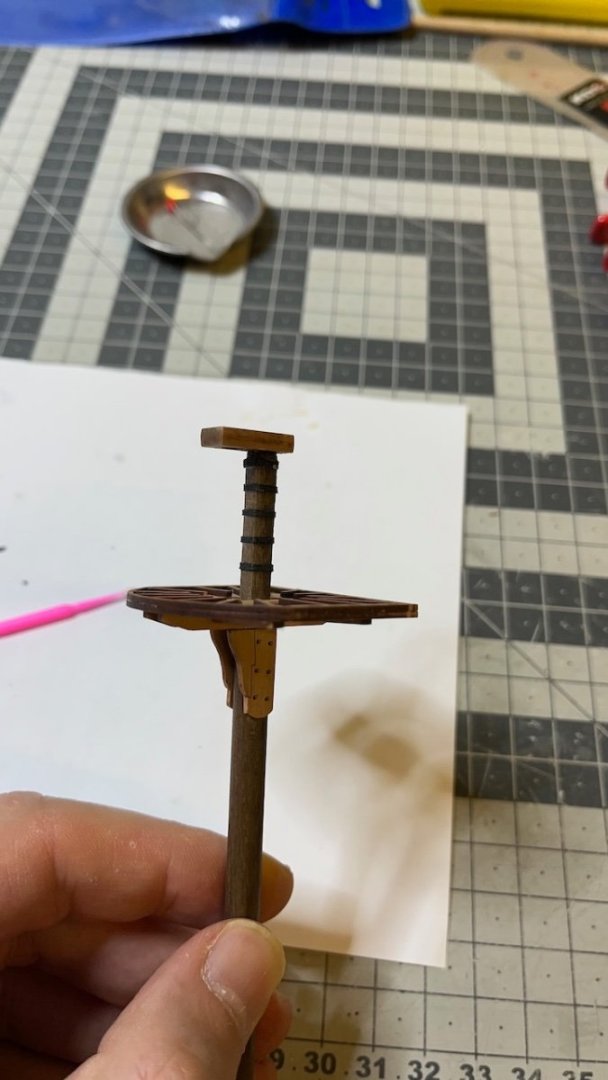
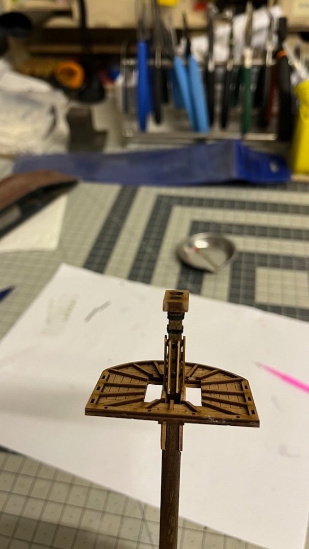
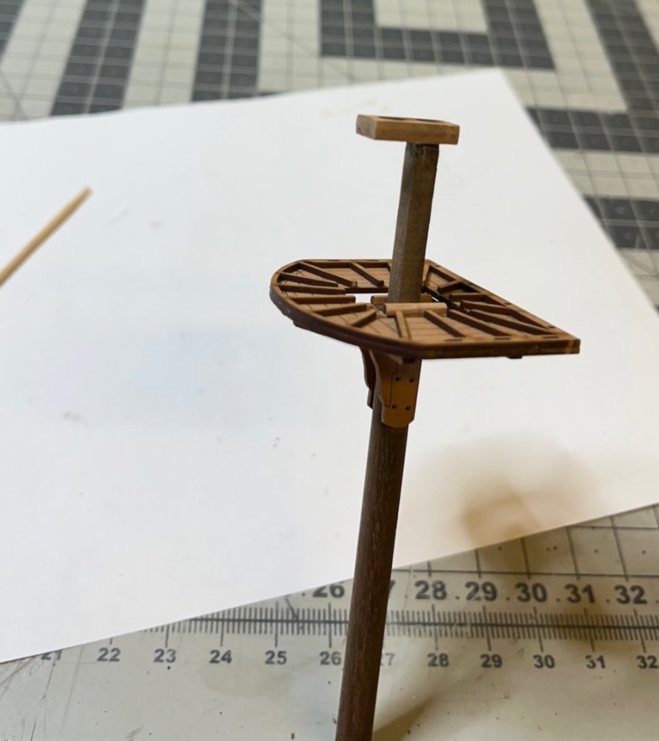
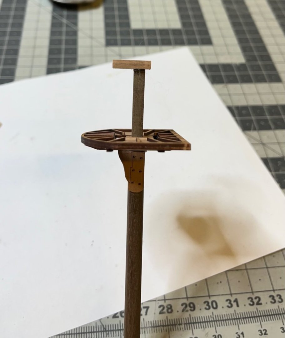
Photos 673-675: Fitting the platform to the mast along with a few other parts. The platform sits slightly inclined towards front to counter the rake of the mast.
- 426 replies
-
- 5
-
-
- Vanguard Models
- Sphinx
- (and 1 more)
-
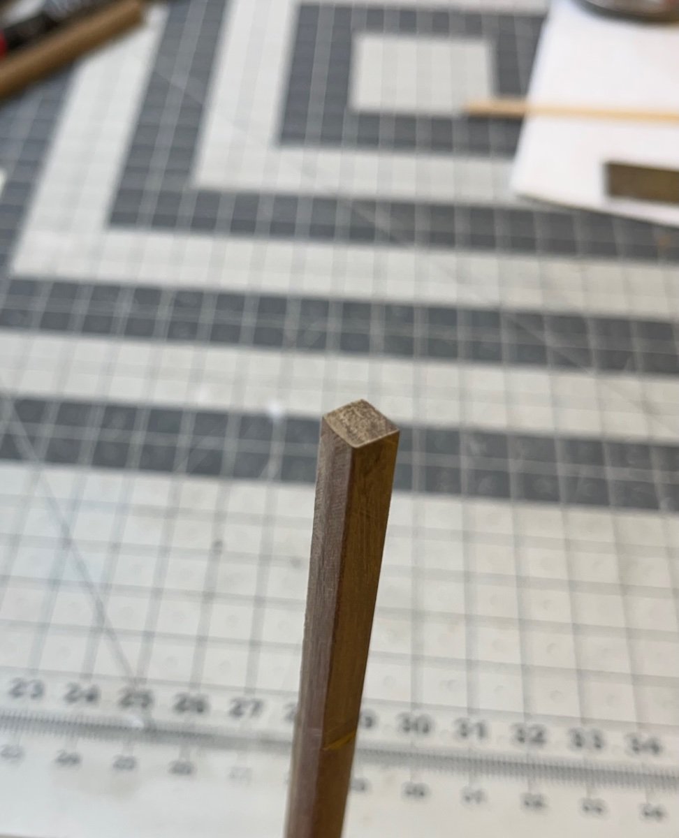
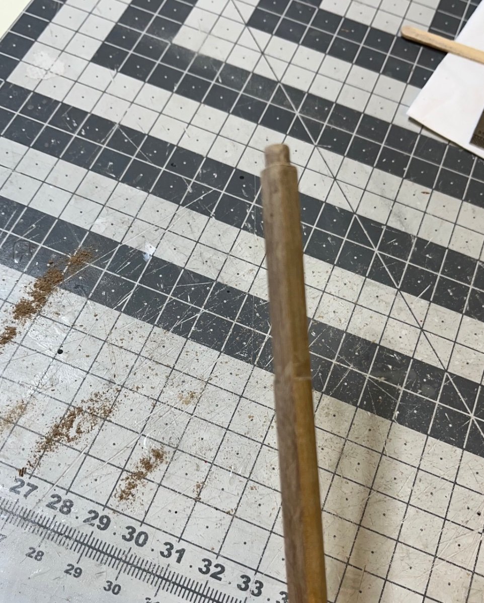
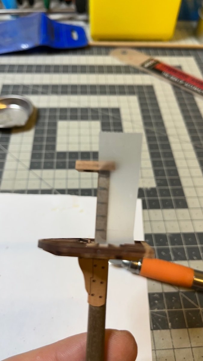
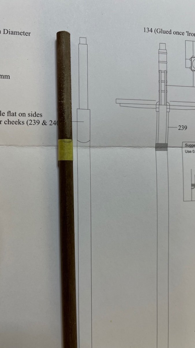
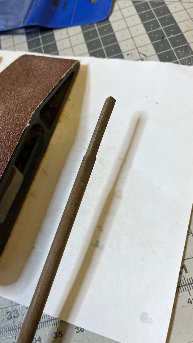
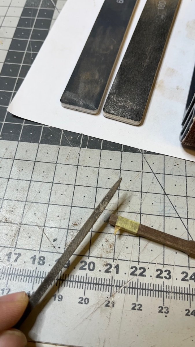
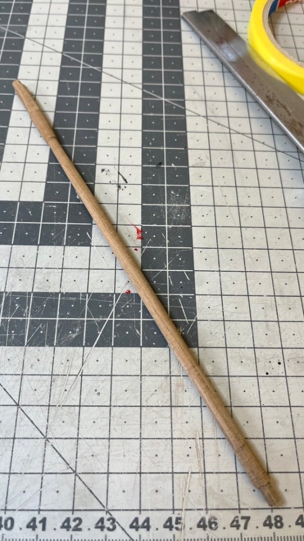
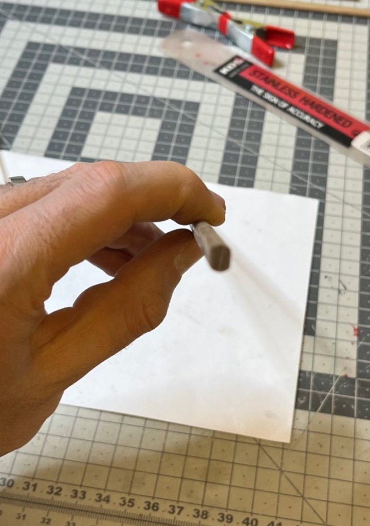
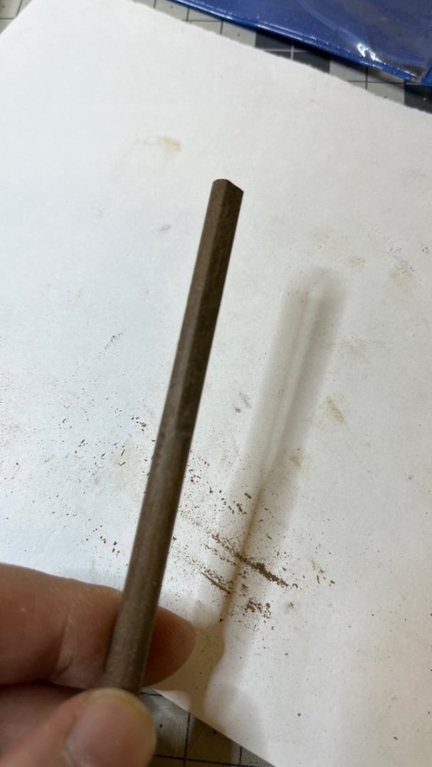
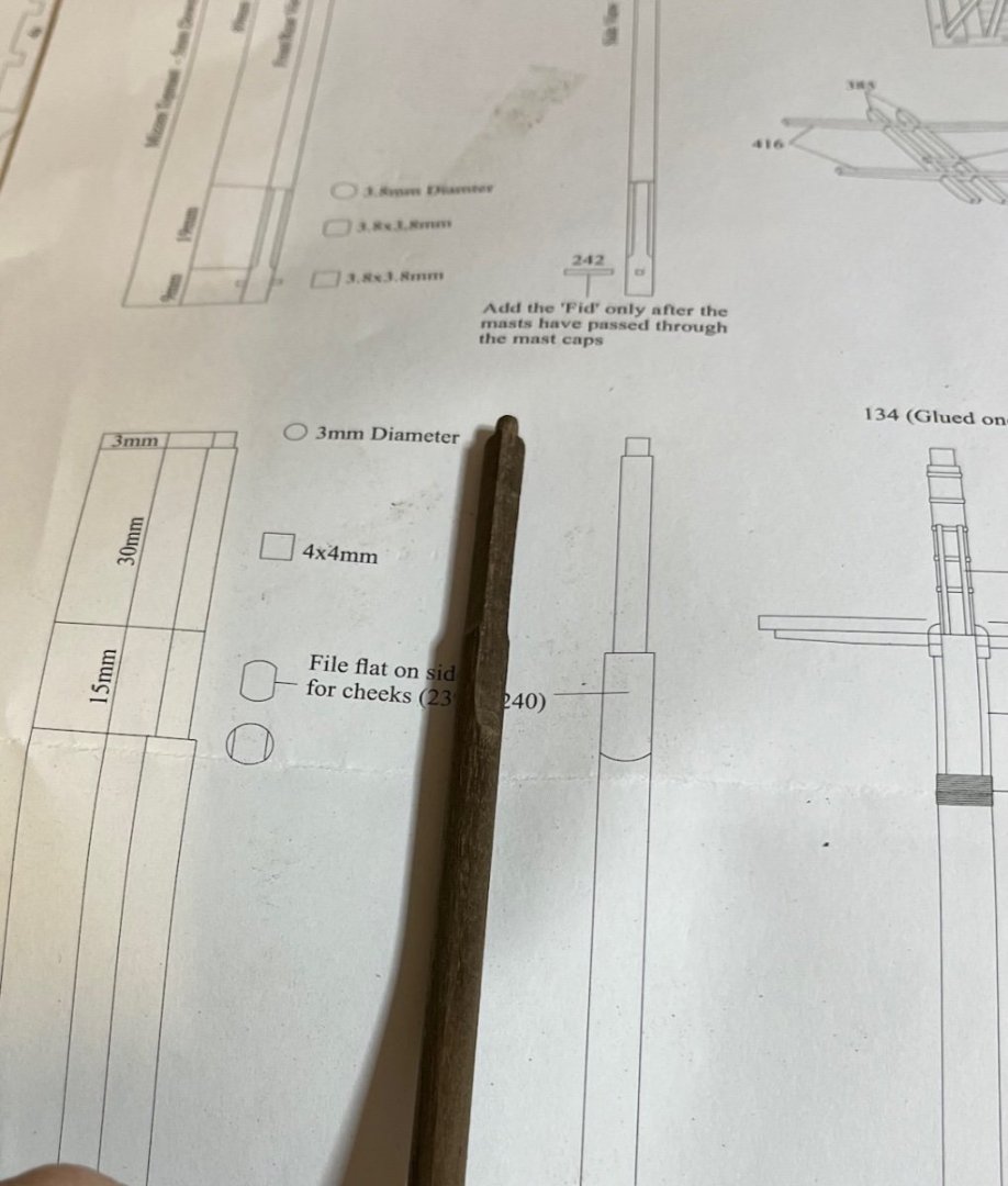
Photos 665-672: Mizzen mast lower section. Though it doesn't have tapering all along, the top part of this section has several change of shapes. Below is a sequence of photos showing the progress. I used rough sanding block, fine sanding sticks, file, masking tape and caliper as you'll see in the photos.


- 426 replies
-
- 4
-
-
- Vanguard Models
- Sphinx
- (and 1 more)
-
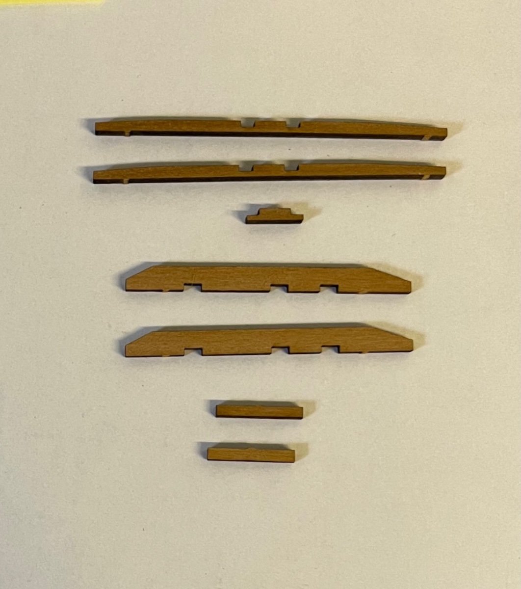
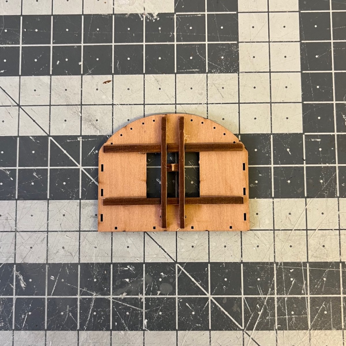
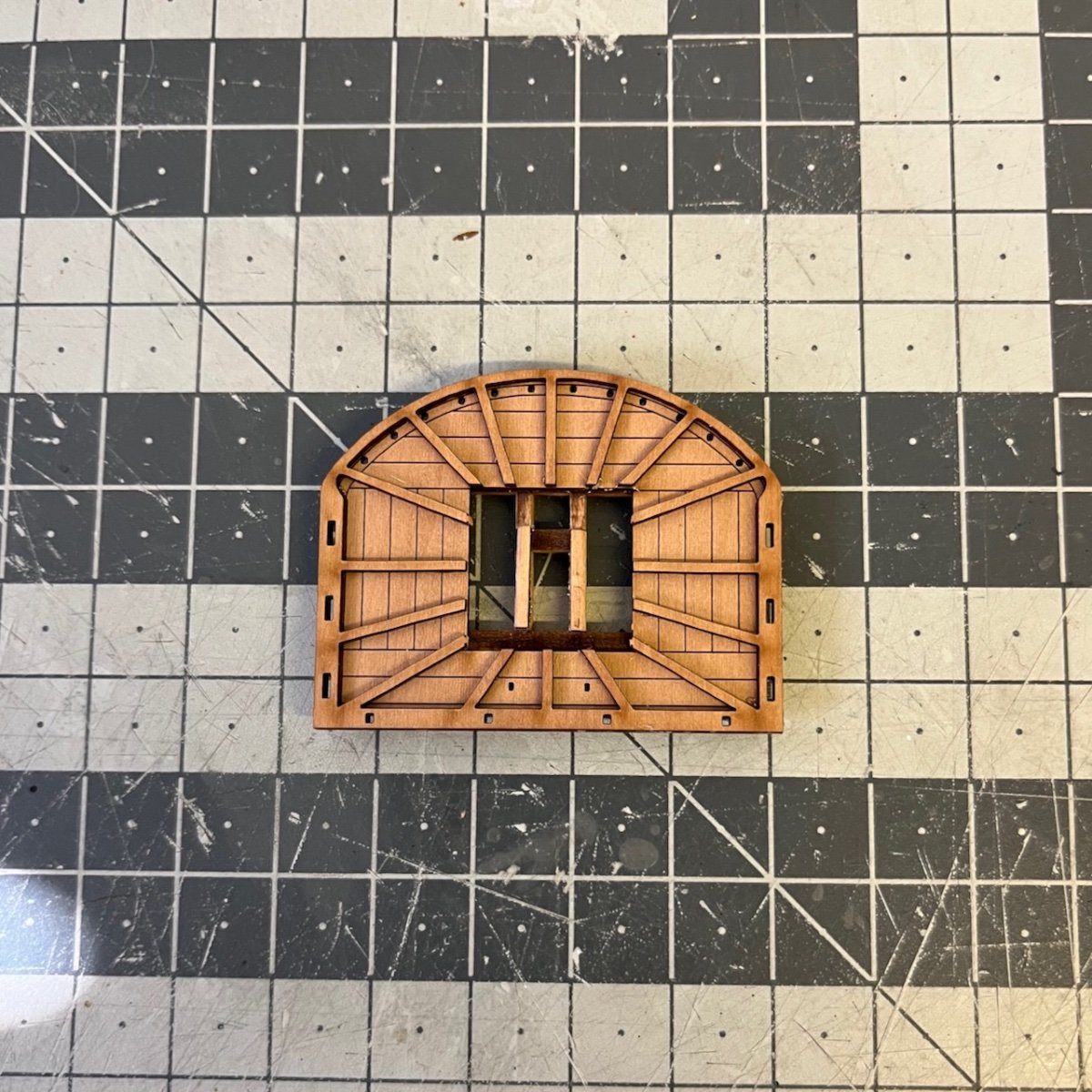
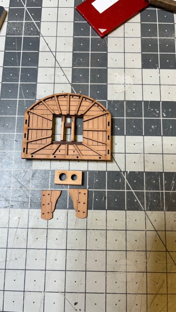
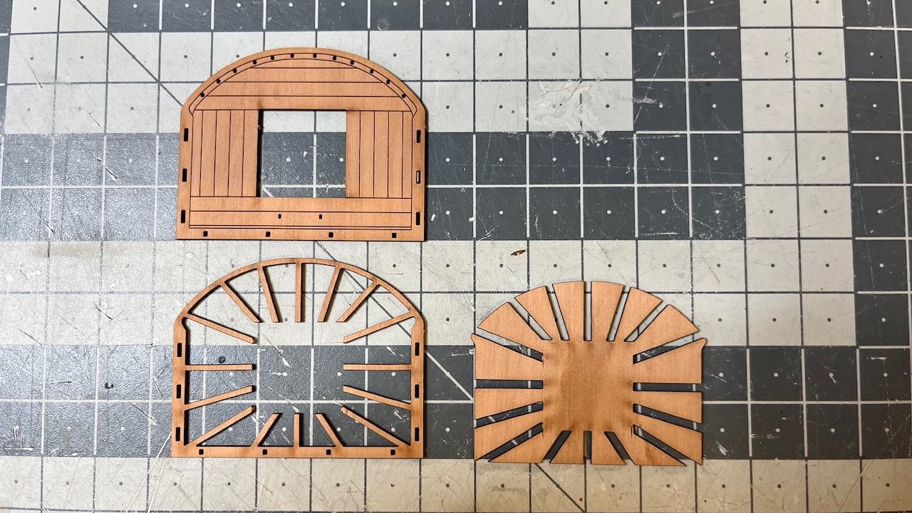
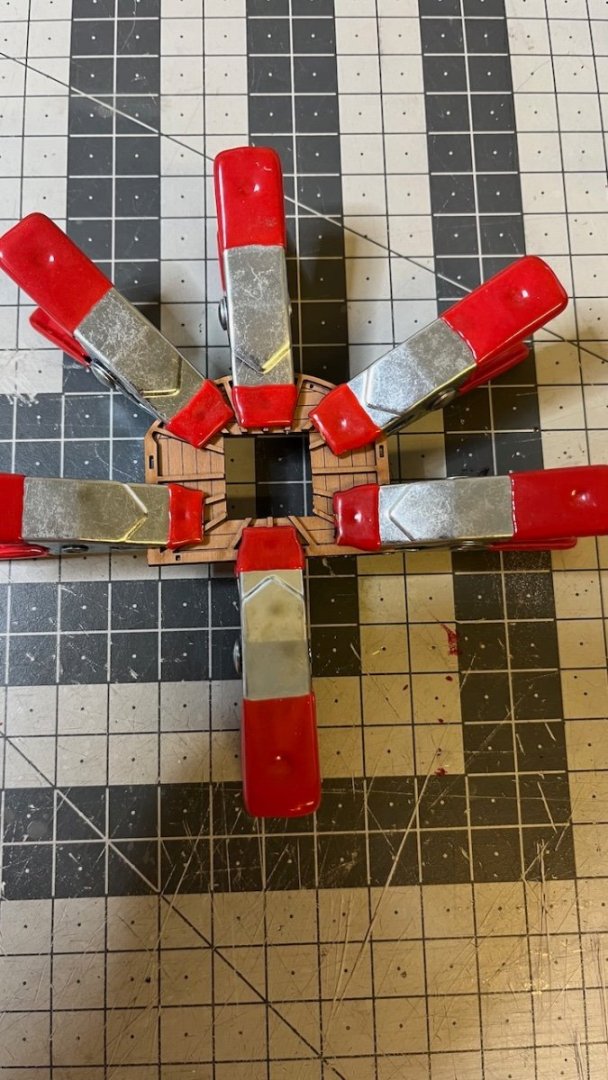
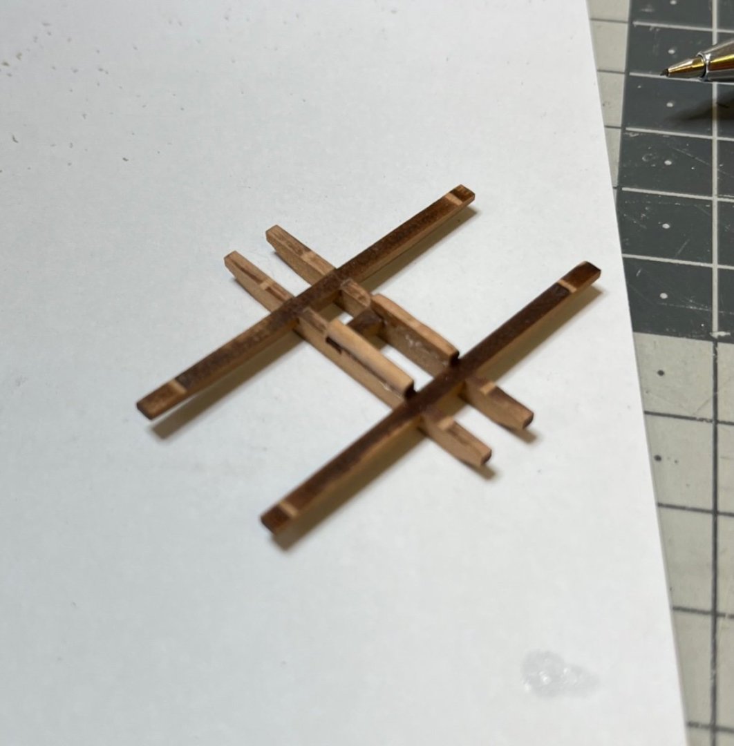
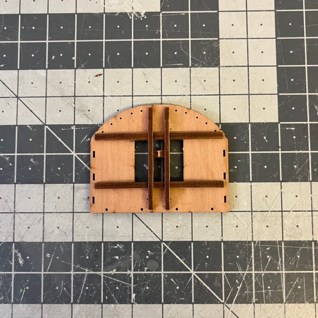
Build days 88-89: 3 hrs / Total 201.5 hours Hitting the 200 hour milestone, now the Mizzen mast construction commences. Every single step in these constructions use the plan as a reference. It is essential for correct alignment of the parts. You need to check everything from all axes (side, front, back) before gluing anything. Photo 659: Starting with the platform. The part looking like an imperial sun on the lower right is actually a scrap of the one on its left Photo 660: I tried to use minimal amount of glue for assembling the two parts, in order to avoid any stains. Micro drops on the tip of the ribs and a few drops around the edge. Photos 661-662: Mizzen cross-tree assembly. After dry fitting, it was aligned so well, I didn't want to remove them for applying glue, so instead I brushed diluted glue on the joints. Photos 663-664: Complete platform assembly


- 426 replies
-
- 5
-
-
- Vanguard Models
- Sphinx
- (and 1 more)
-
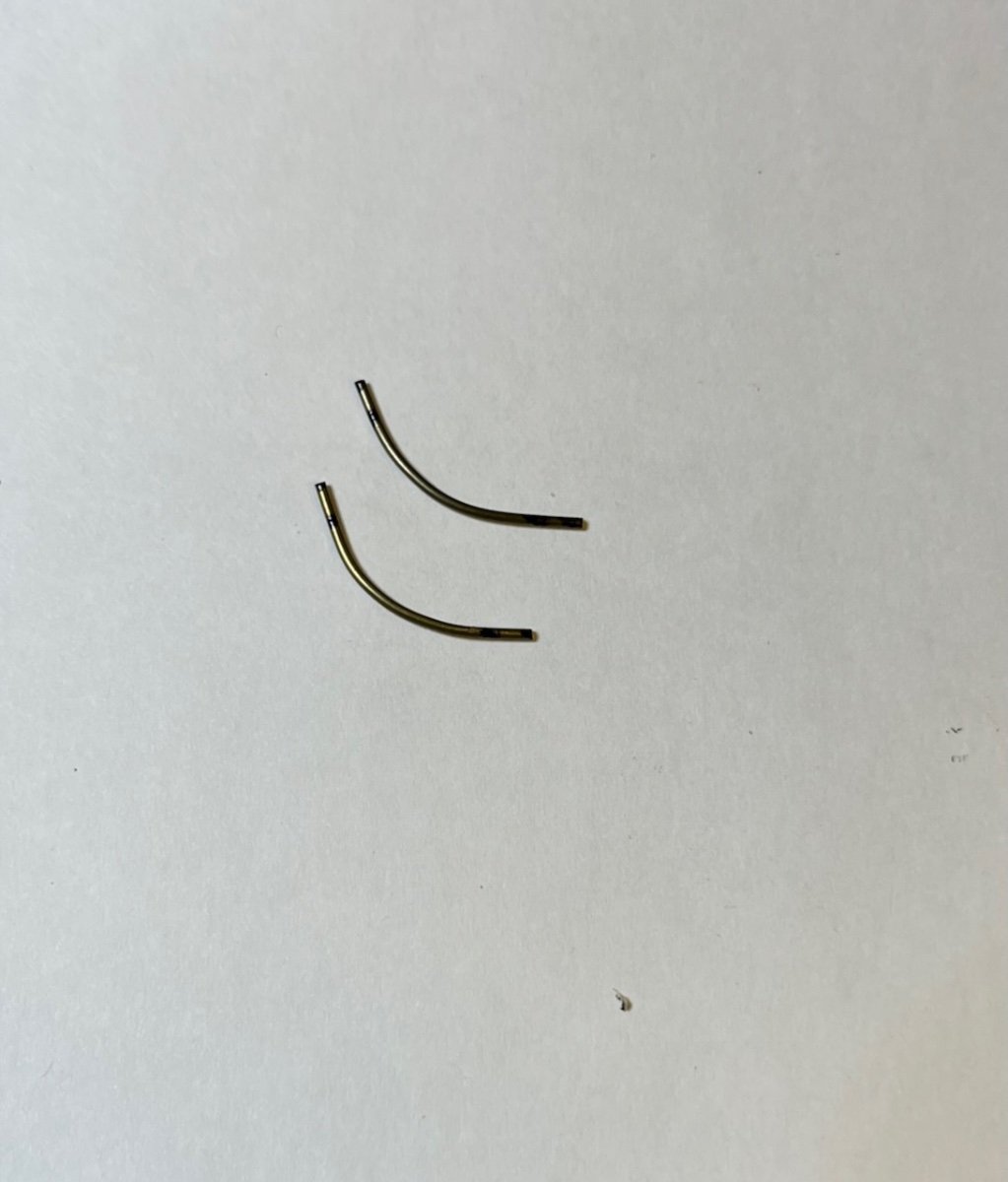
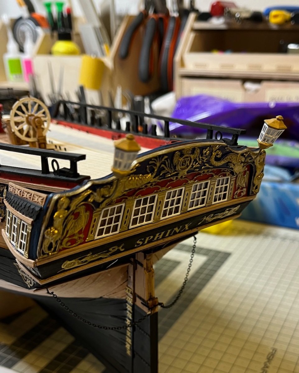
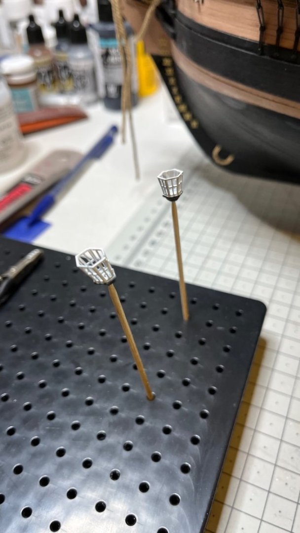
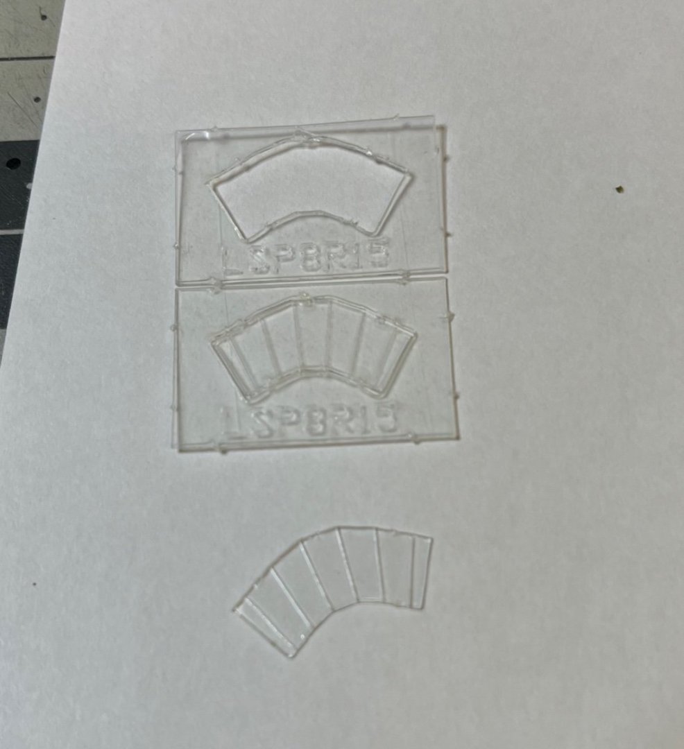
Build day 87: 2 hr / Total 198,5 hours Photos 655-657: Lantern construction. Refer to plans for preparing the rods and final positioning of the lanterns on the stern. Photo 658: Lanterns in place. That's all for now. Thanks for watching!


- 426 replies
-
- 13
-
-

-
- Vanguard Models
- Sphinx
- (and 1 more)
-
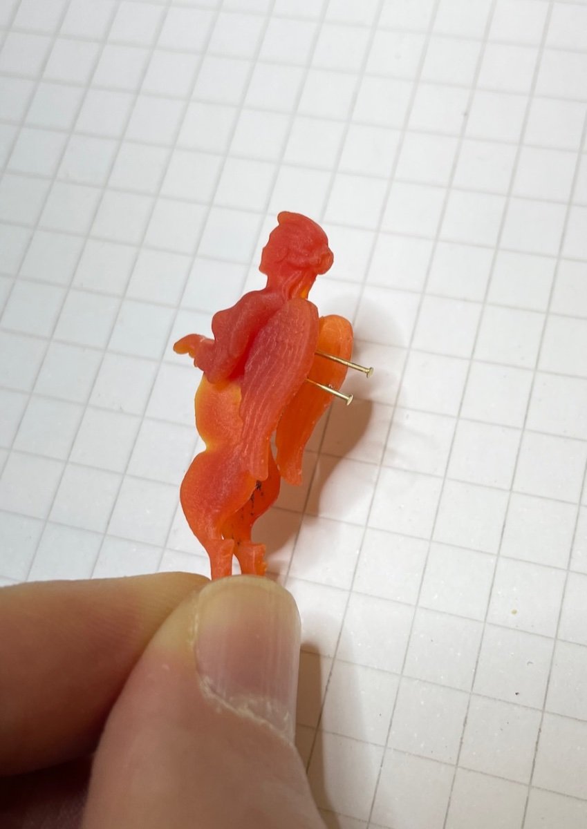
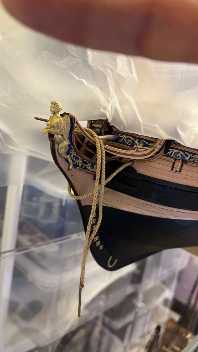
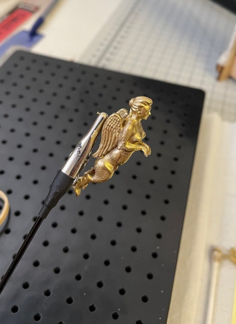
Photo 652: Figurehead, nicely detailed. I inserted two nails at the back to help grab while painting. Photo 653: Painted in gold (I used Vallejo Liquid Rich Gold available in my paint box) after priming with white primer. Photo 654: Figurehead in place.


- 426 replies
-
- 9
-
-
- Vanguard Models
- Sphinx
- (and 1 more)
-
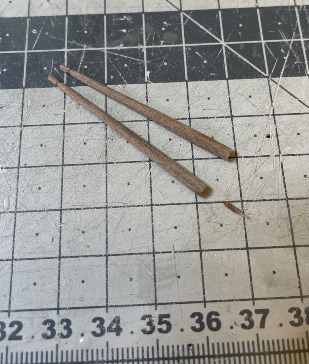
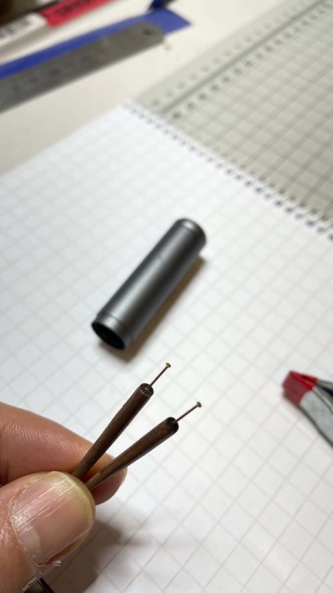
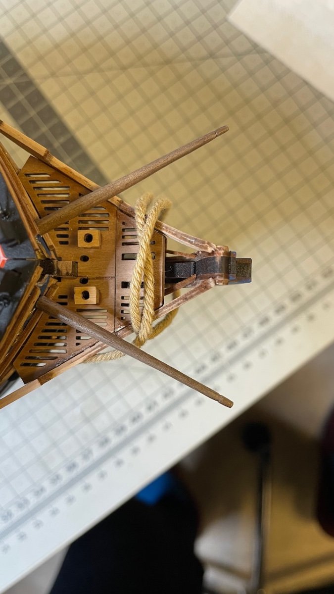
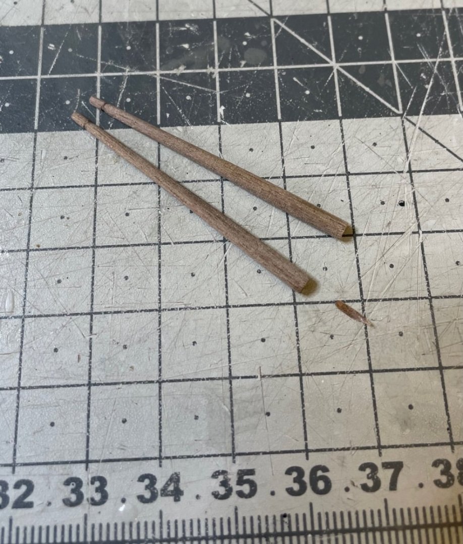
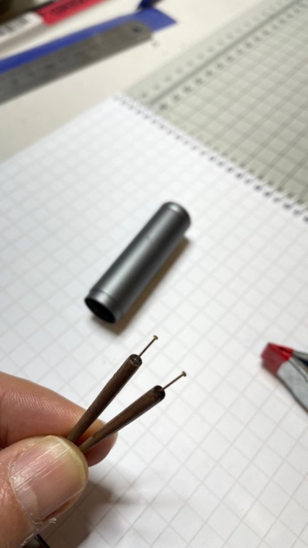
Build day 86: 1 hr / Total 198,5 hours After the boats, the hull is back on the table for completing three details left before starting masts and yards: Boomkins, the figurehead and the lanterns. Photo 648 : boomkins are made of 46mm long 3mm diameter walnut dowel, tapered to 1mm thickness at the other end, as per the plan. Photo 649: I used my handheld Proxxon and a sheet of sand paper for tapering. Photo 650: Nails for fixing them to bow (nail tips clipped before doing so) Photo 651: Boomkins in place taking care of the alignments from the plan.


- 426 replies
-
- 6
-
-
- Vanguard Models
- Sphinx
- (and 1 more)
-
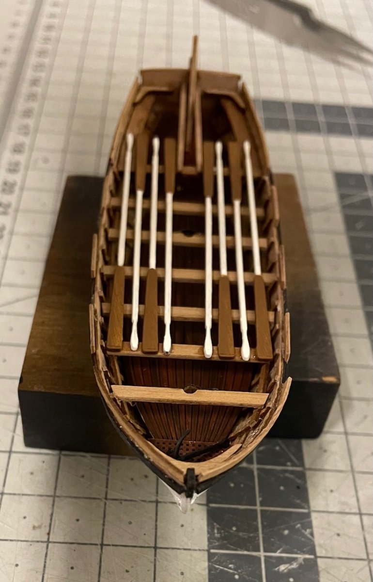
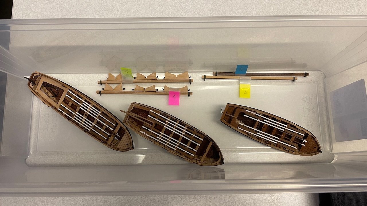
Build Days 82-85: 7 hours / Total 197,5 hours Photos 643 - 646: 22-foot Yawl construction, spread to 4 build days from April 13th to April 16th, altogether 7 hours. Build sequence goes similar to former two boats hence not many details worth sharing here either. Photo 647: All boats safely in a box, waiting to be mounted permanently, which will take place after some progress with rigging, as per the instructions. That's all for today. Thanks for watching!
- 426 replies
-
- 8
-
-
- Vanguard Models
- Sphinx
- (and 1 more)
-
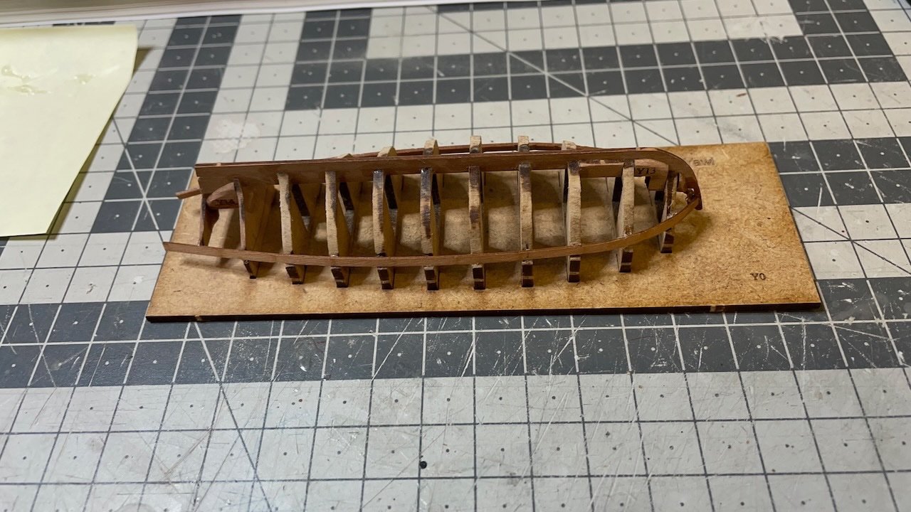
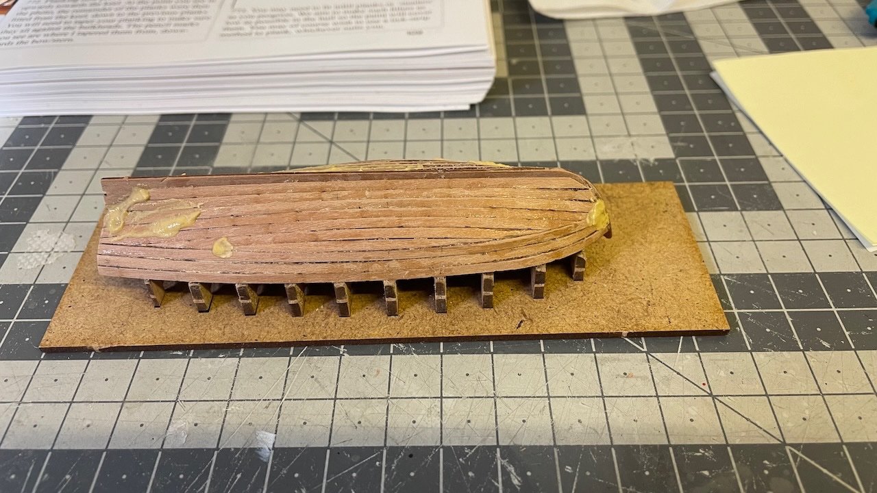
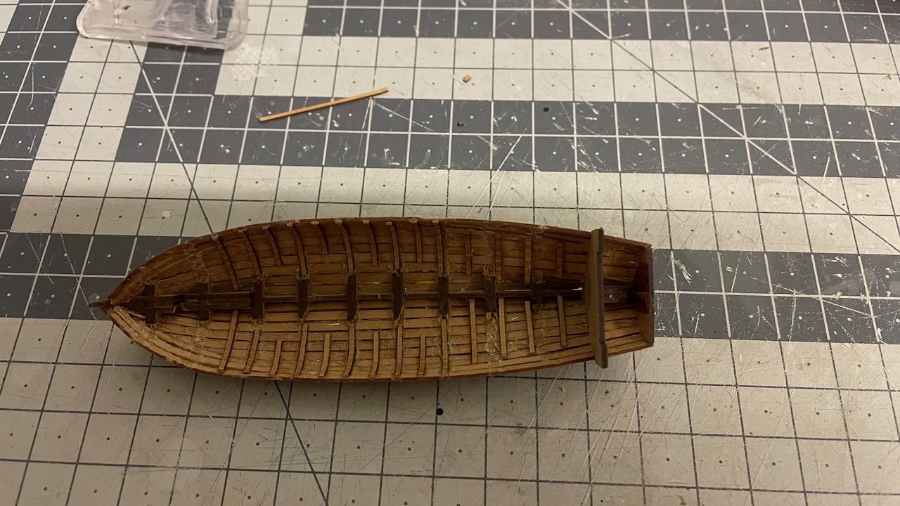
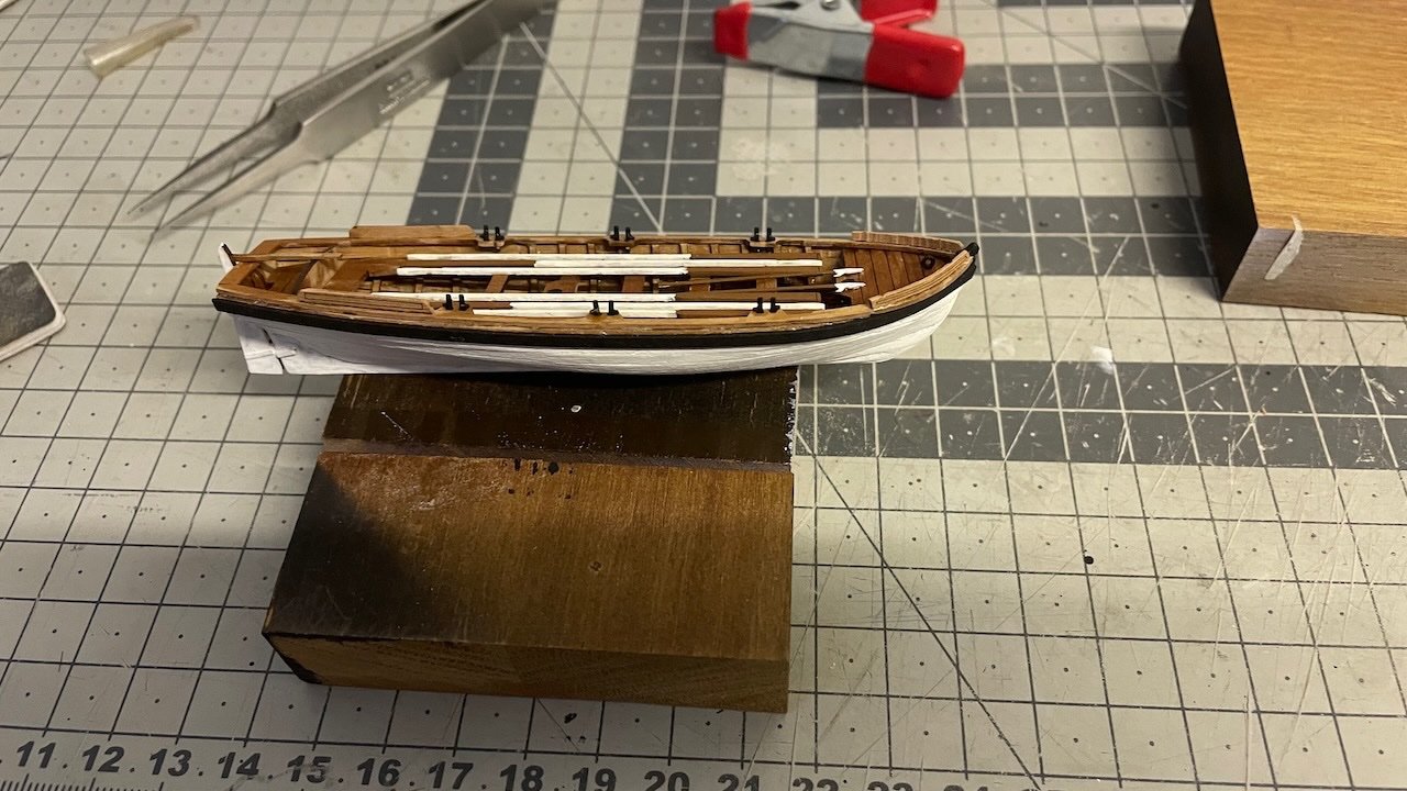
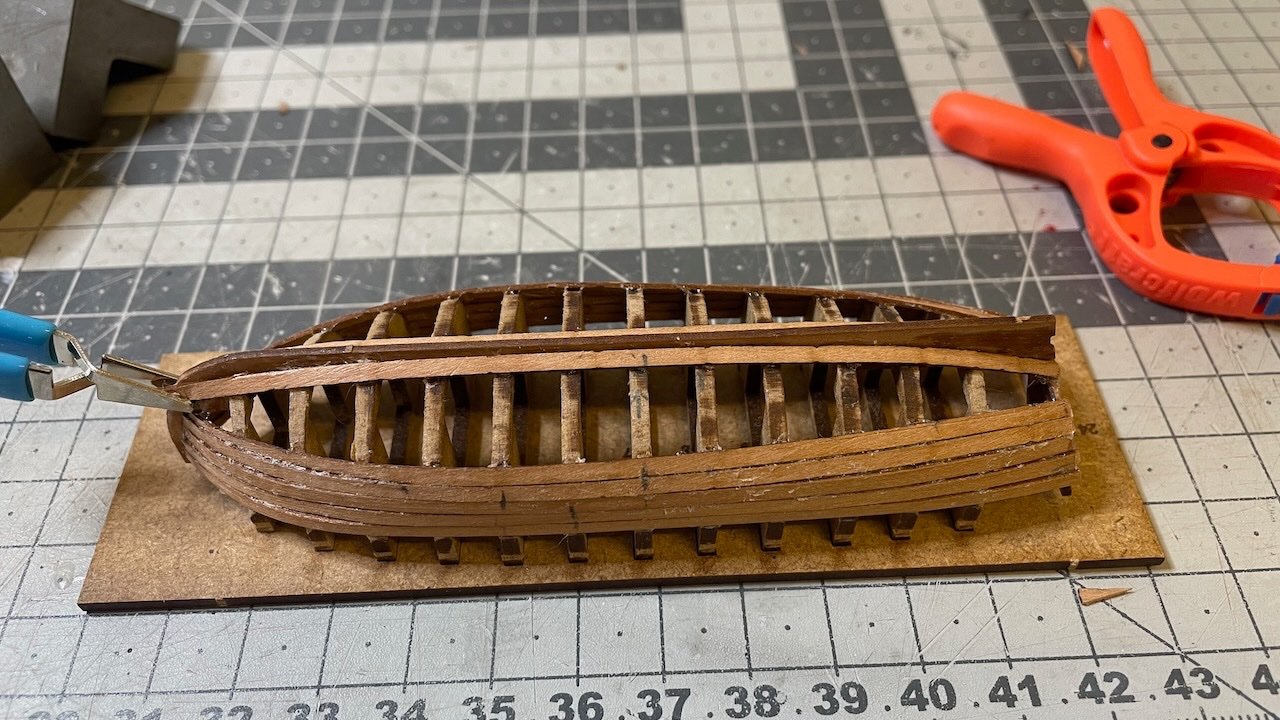
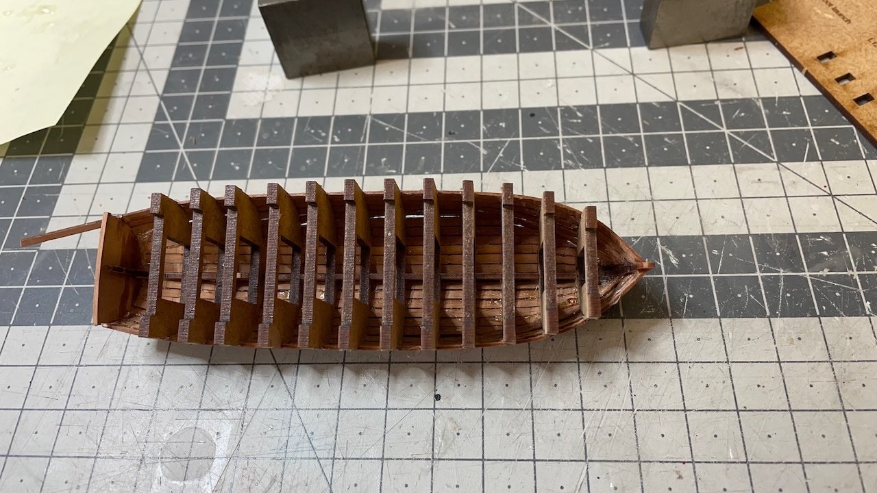
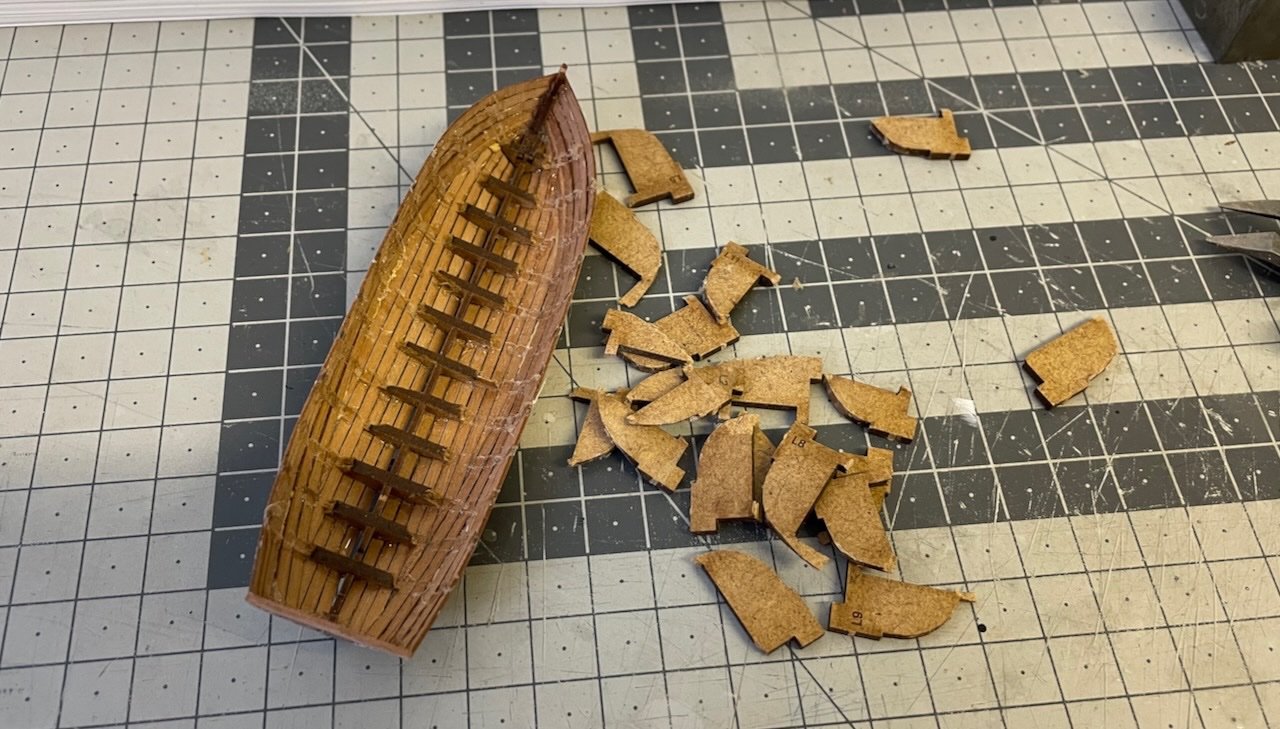
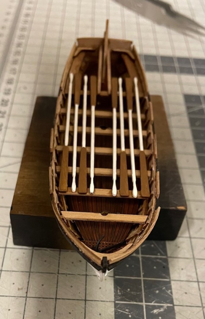
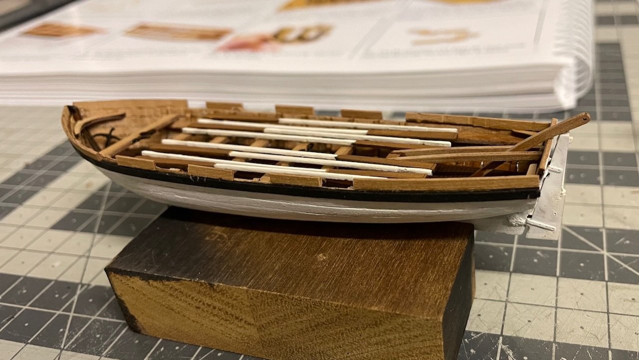
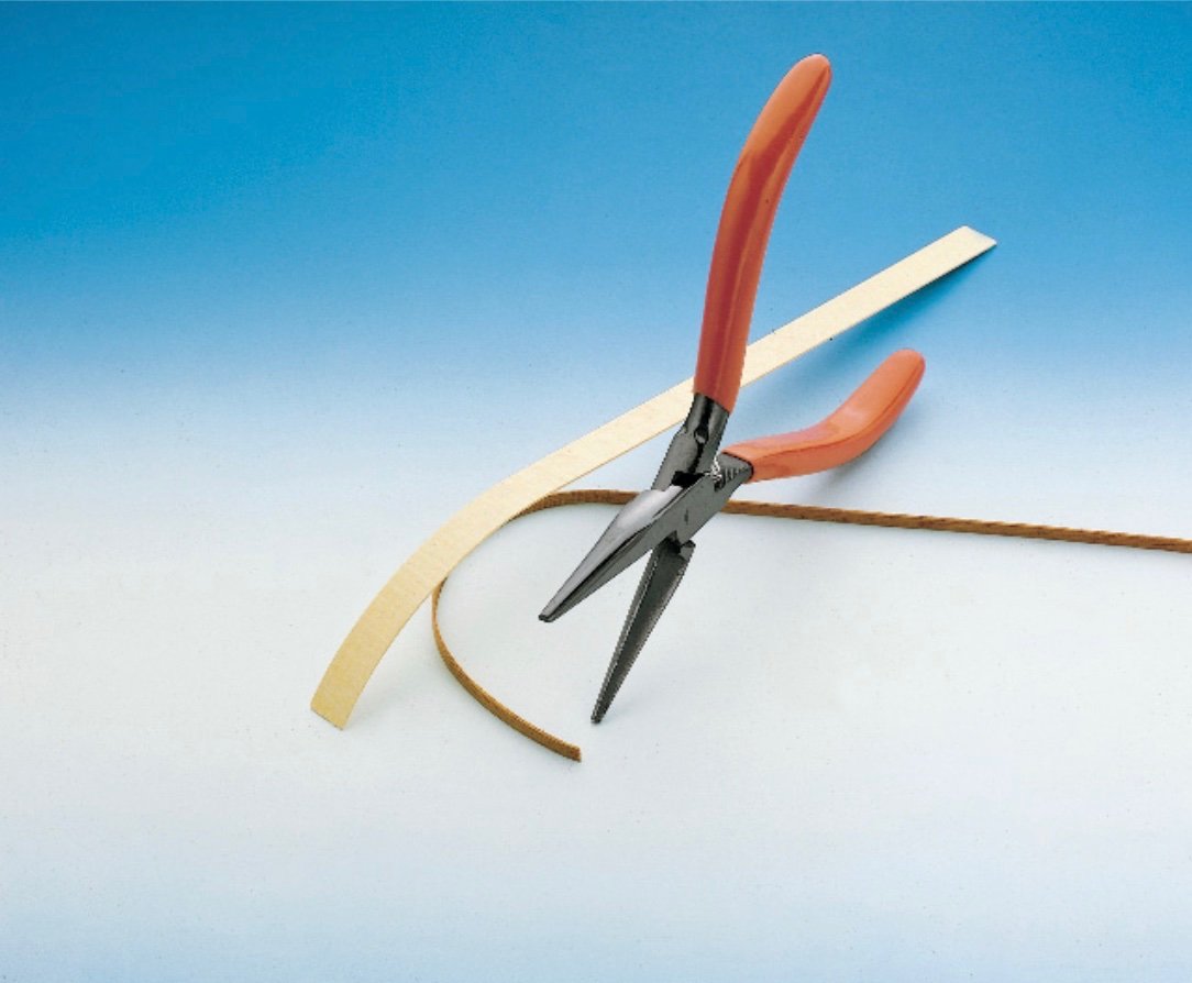
Build Days 76-81: 12,5 hours / Total 190,5 hours 24 Foot Launch construction, spread to six build days from March 23rd to April 10th, altogether 12,5 hours. Build sequence goes similar to the 28 foot pinnace hence not many details worth sharing here. Photo 637: I use this plank bender throughout (bought from Mikromark), which leaves dents on the inner surface, which is partly visible. Using an electric heat bender would give a smoother result but it would take much longer time and anyway this looks acceptable to me. The number of seat benches in my boat is one less than in the plan. It was due to spacing them maybe 1-2 millimeters wider than normal. Fitting the last bench would look too tight so I just left one out. I also made four openings for oarlocks, one for each of the 4 pairs of oars. Photos 638-642: Here is the progress. That's all for today. Thanks for watching!
- 426 replies
-
- 8
-
-
- Vanguard Models
- Sphinx
- (and 1 more)