tedrobinson2000
-
Posts
153 -
Joined
-
Last visited
Content Type
Profiles
Forums
Gallery
Events
Everything posted by tedrobinson2000
-
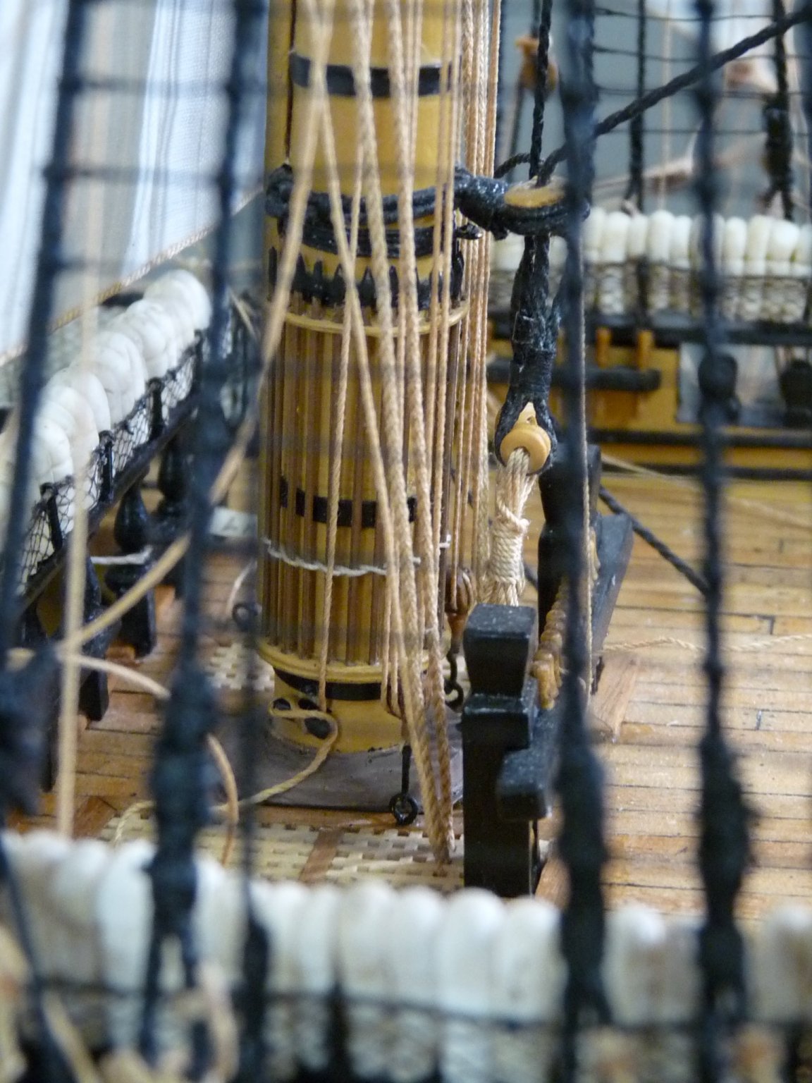
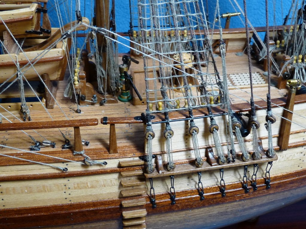
This is a shot of some of the belays at the foot of the main mast. Here the port truss pendant tackle fall is being attached. Belay of main course sheet at starboard staghorn.

-
I have a related question- seems silly. I would like to post a picture, then add some commentary about what's shown, then add another photo and continue, posting several pictures in a single upload, with comments interspersed. Seems after a photo is uploaded, I can't get the cursor to go to a spot where I can add some text before I upload the next picture. All photos seem to appear serially after any text. Any solutions?
-
Jeers bowsed up. Note that the running ends were pre-attached to the bitts on the upper gun deck, abaft of the main mast. This was done ages ago, before the quarter deck was installed, which would have made access impossible. Same goes for several other lines, such as the fore yard shhets, main yard tacks, main top yard sheets, etc.
-
Reeving jeers.\; sling routed but not snugged up yet, Trusses attached to yard, but not yet routed correctly.
-
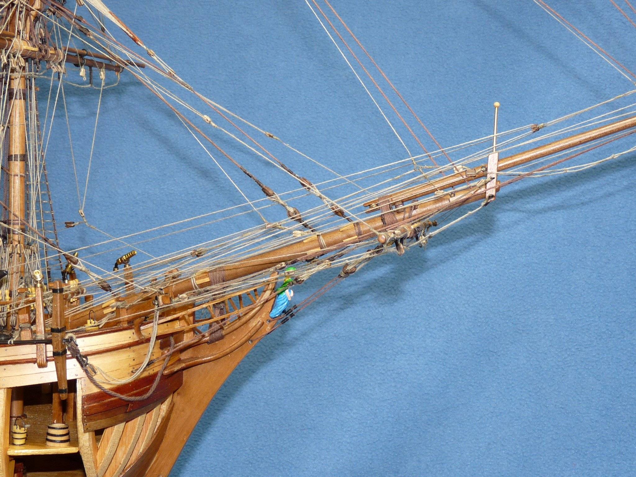
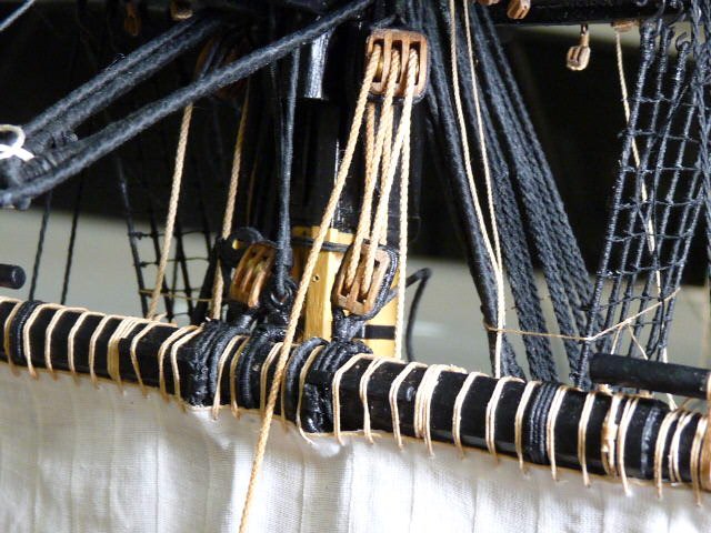
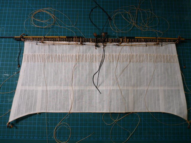
I haven't posted here for the last 5 weeks or so, but here are some updates. Again, I apologize for the cockamamie way that I am posting; a mix of historical pix from the early stages of the build, and some current ones. I finally got to shipping the main yard/course a few weeks ago. The yard/sail assembly with most lines pre-attached:
-
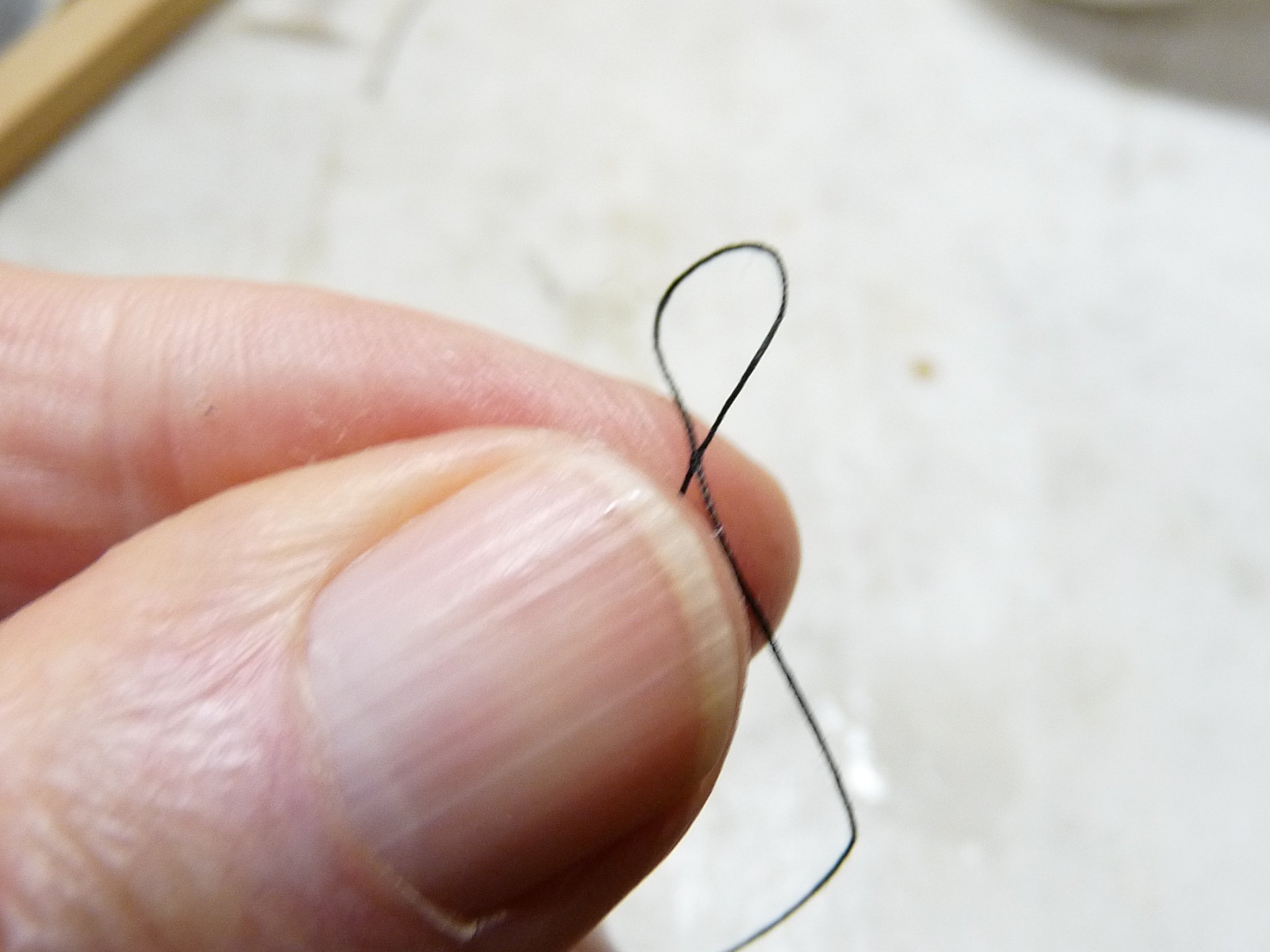
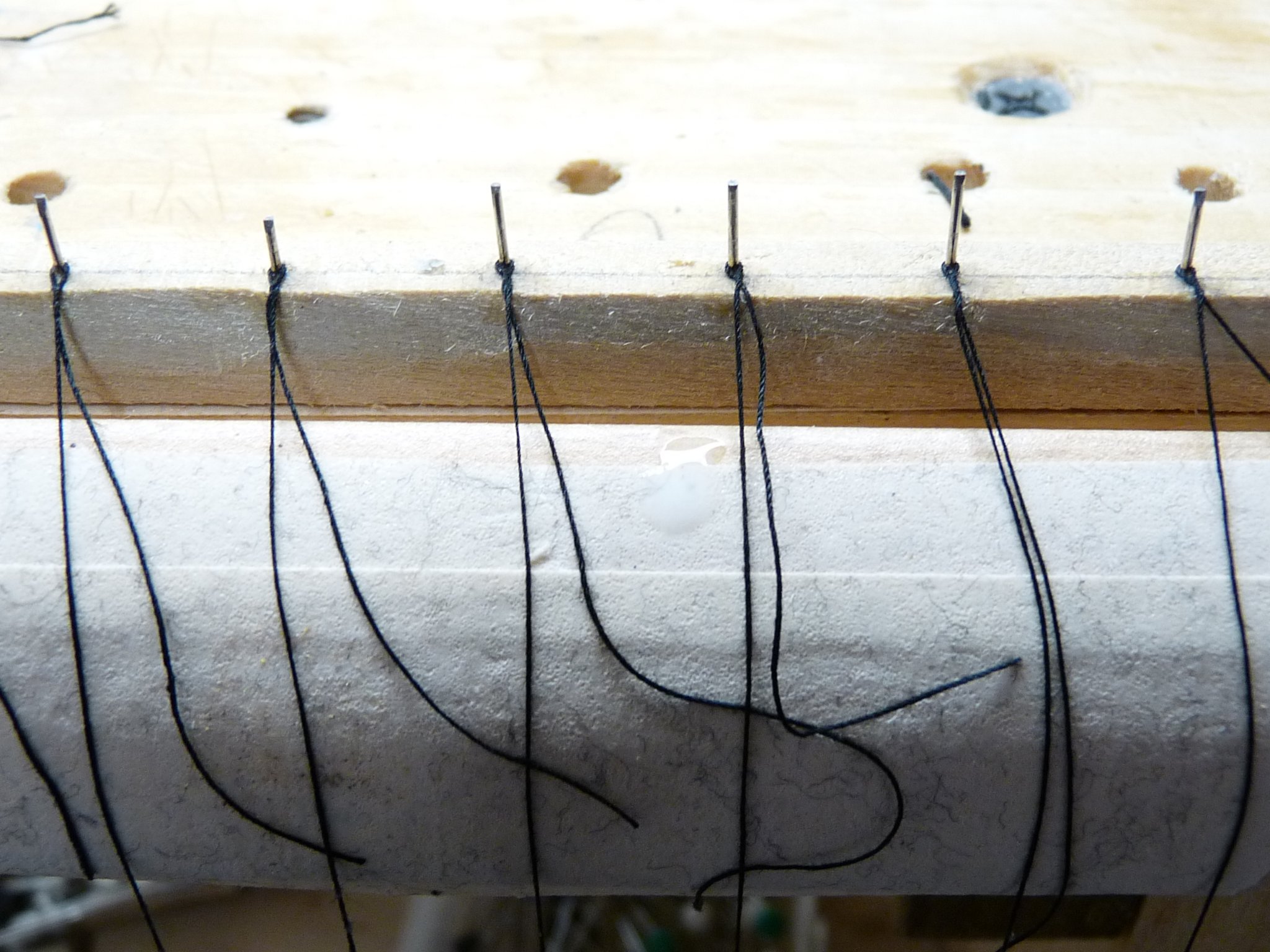
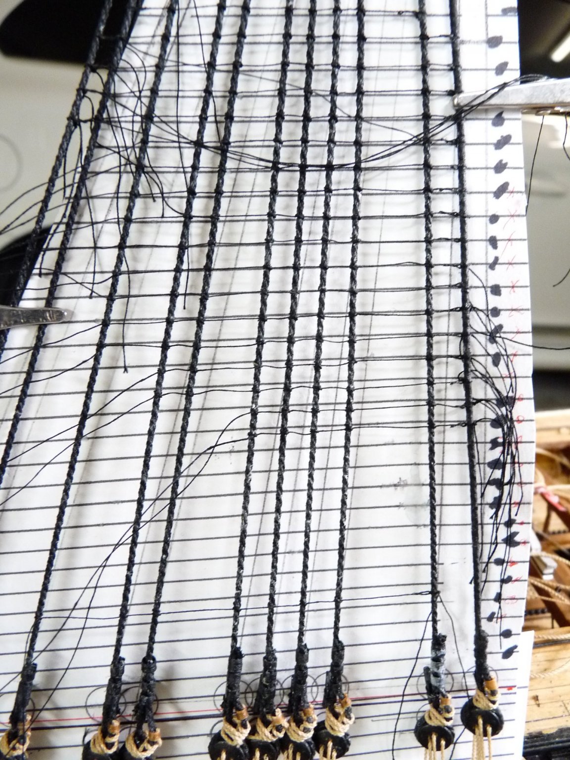
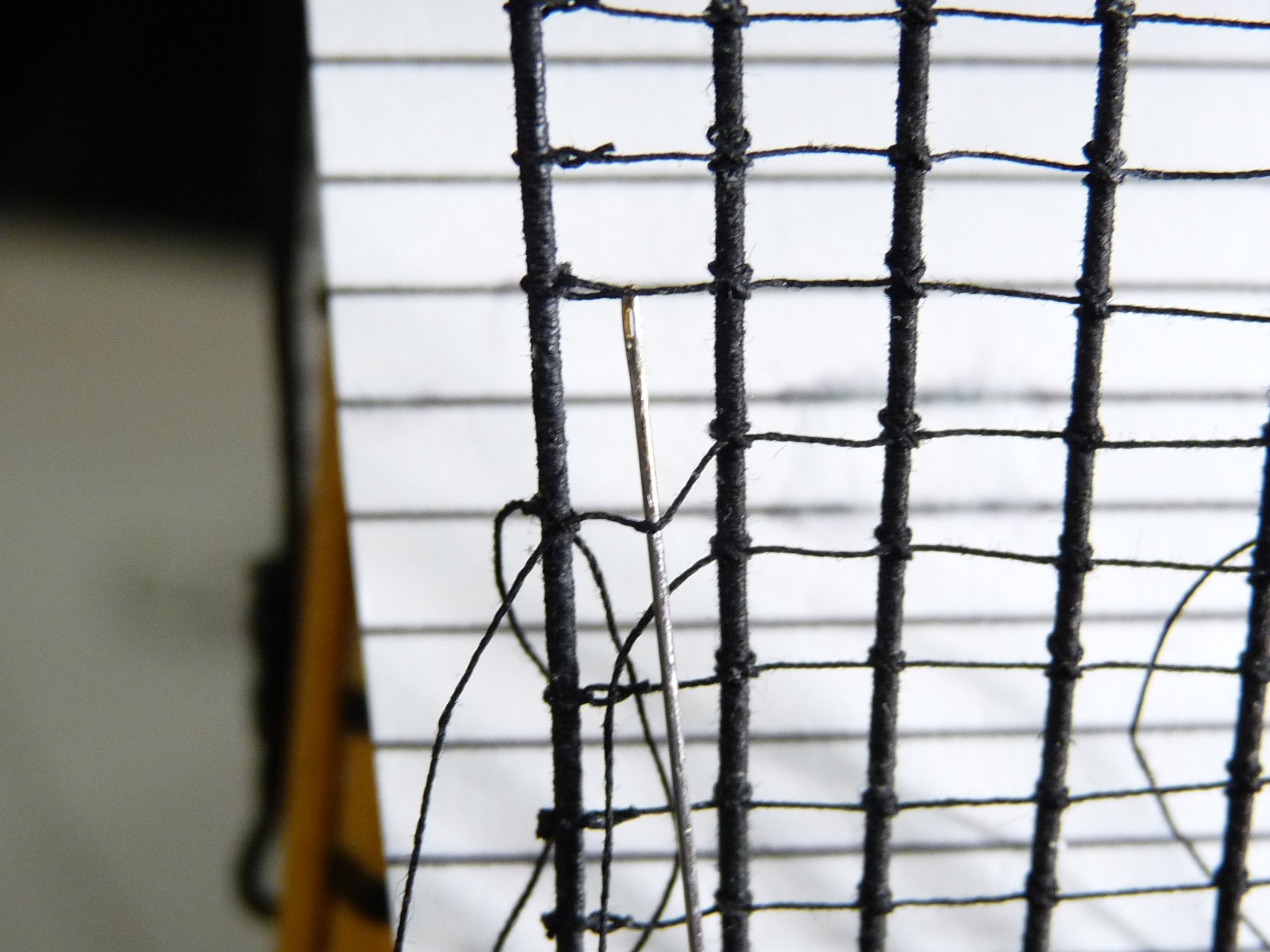
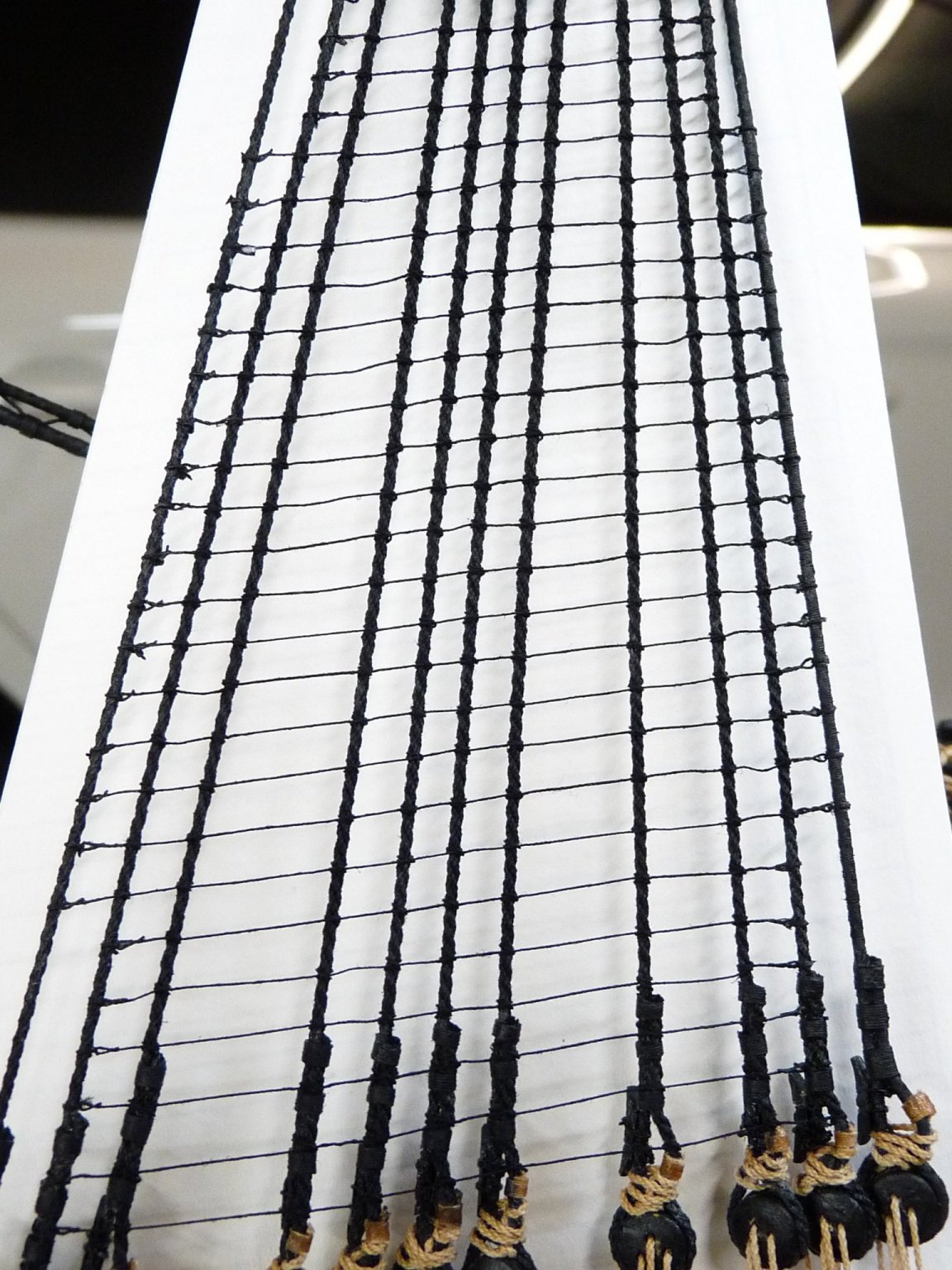
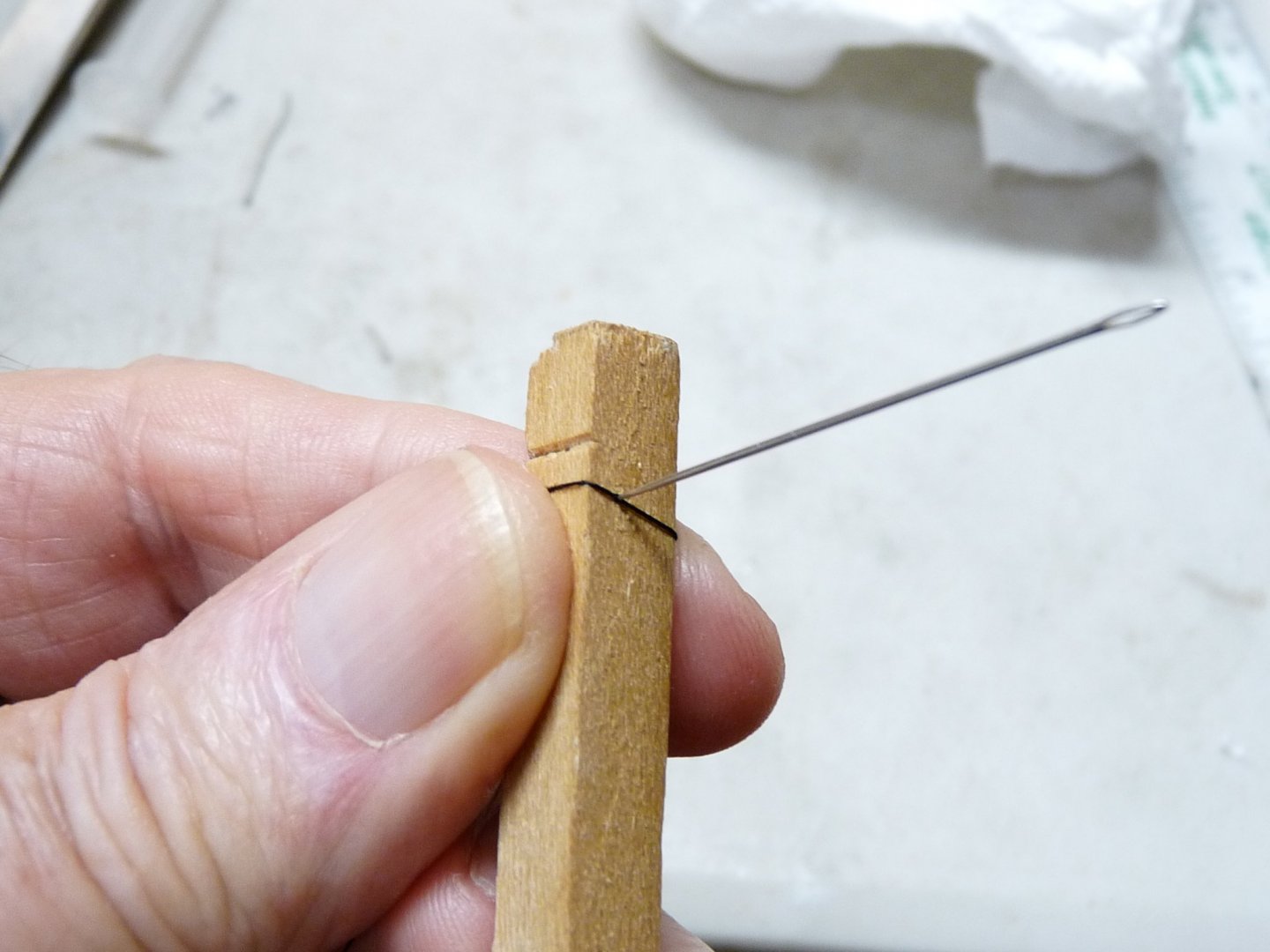
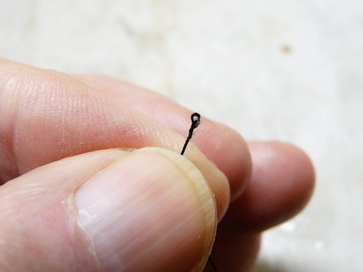
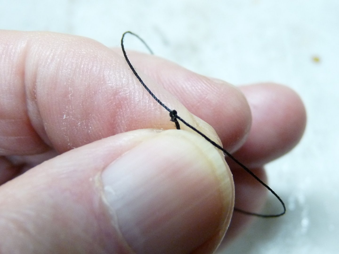
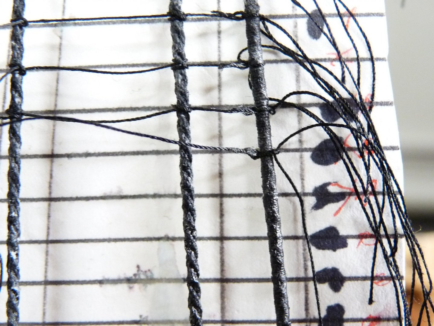
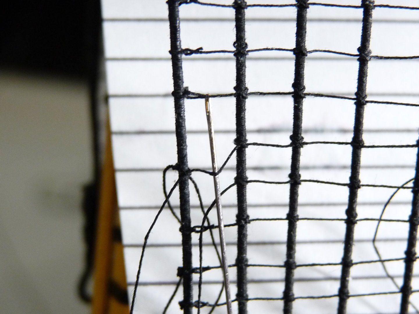
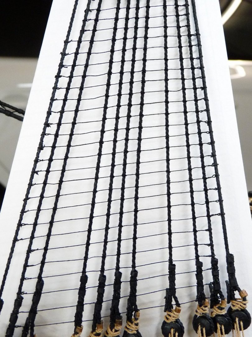
Hi Dave, I am in the midst of my Caldercraft 1:72 Victory, and had the same questions as I approached the ratlines. I wasn't happy with the rope supplied with the kit, so I made my own using Coats Quilt+ 100% cotton thread and Chuck's Syren Rope Rocket. The thread mics up at about 0.010", and has little or no fuzz. The smallest diameter rope I could make with the thread is two turns, which makes a rope about 0.013" dia. I tried that as ratlines, but it looked too big ( at scale of 1:72 it would have been almost an inch in diameter). So, I opted to use a single thread of the Coats for the ratlines. I developed a method (not saying it's right, but it worked for me). I wanted to have each ratline terminate at the 1st and last shrouds with a spliced eye, and clove hitches on the intermediate shrouds. I made the eyes by piercing the thread at one end, making a loop to form the eye. I then wetted the line with 50/50 Elmer's School Glue and stretched it taut. Elmer's SG has the property that it dries hard and clear, but will soften again when dampened. To begin, I started on the right-hand shroud (only because I am right-handed) and lashed the eye in place. Note that having a pattern in the background is a must, as is placing temporary spreaders at points up and down the shroud set to prevent pulling them out of alignment. Lightly dampen the line with wet fingers to soften it as you work. Place the clove hitches on the shrouds as you work your way towards the left. When you get to the last shroud, lash the line in place, then pierce the thread again to make the final eye in place. Put a dab of Elmer's at either end at the eye splices to hold them in vertical position according to your background pattern. Don't worry too much about the vertical position of the intermediate knots; they will slide up and down the shrouds slightly later on when you do the final alignment. After all is done, a final 50/50 wash with the Elmer's darkened with a little black paint locks everything in place. I know this sound involved, but I'll add a few pix to show what I mean. If it interests you, let me know and I'll post some more details on the methods used to make and install the ratlines. Regards, Ted


-
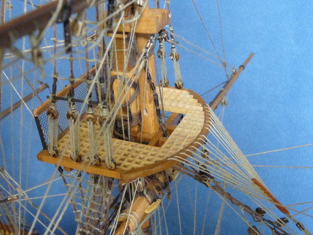
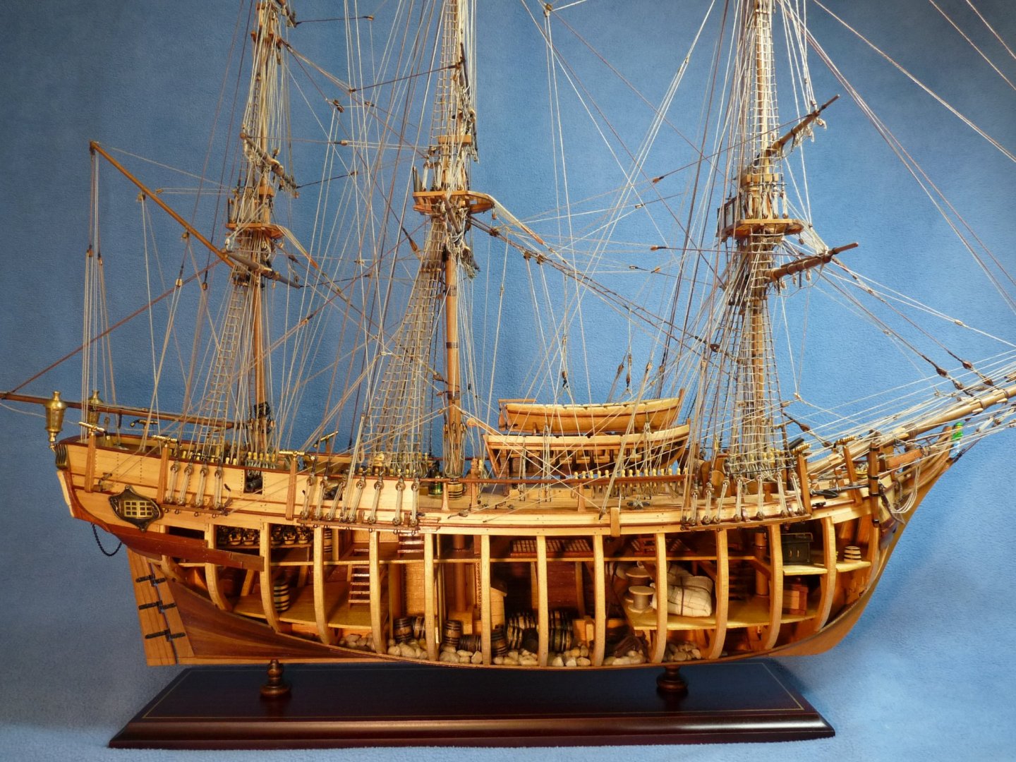
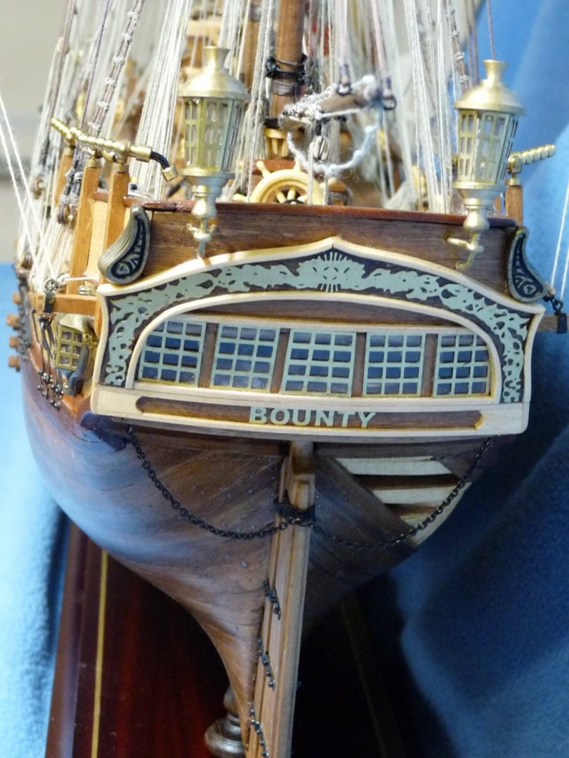
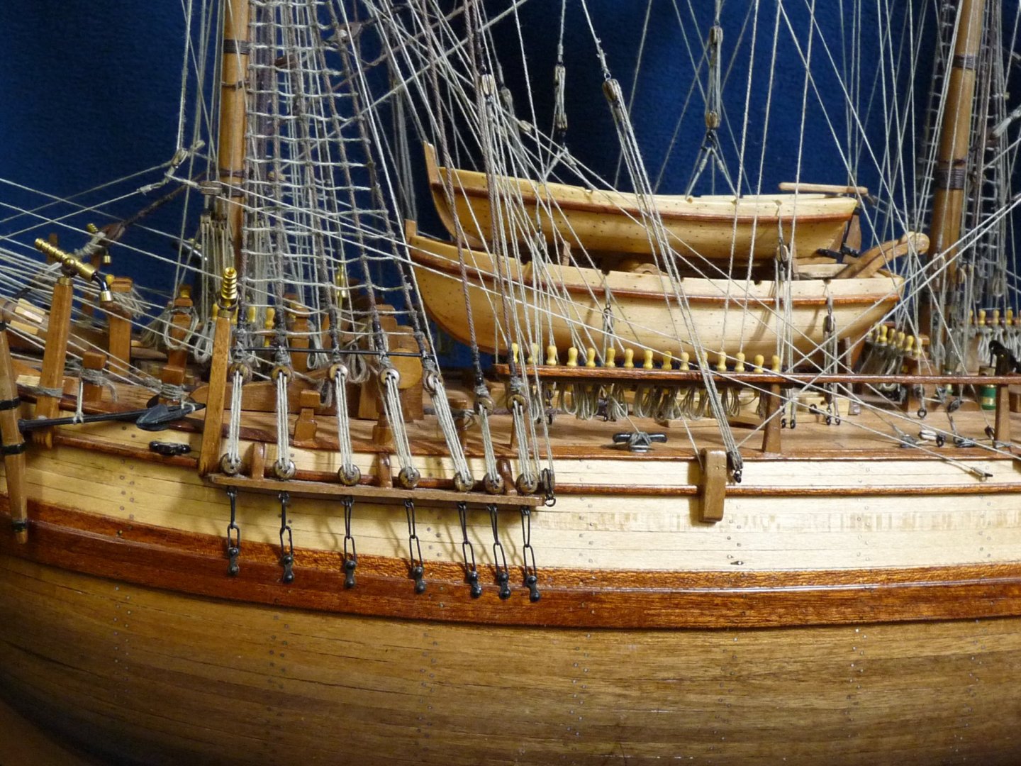
HMS Bounty - Artesania Latina model
tedrobinson2000 replied to Drew Mackay's topic in Masting, rigging and sails
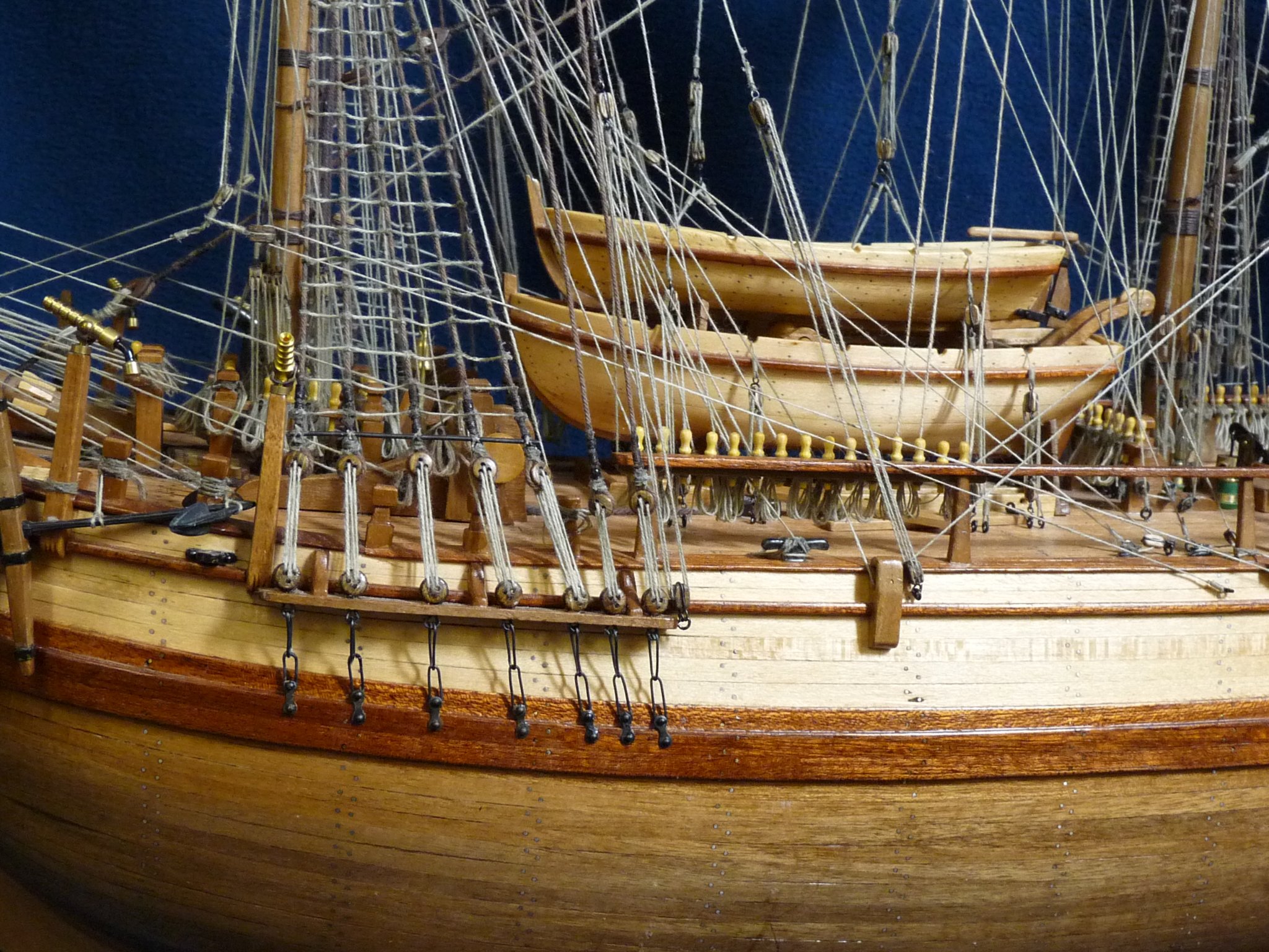
Hi Drew, I did the AL Bounty, finishing it about 12 years ago. I never posted a build log here on MSW, and didn't keep the plans. I'm more than a little rusty, but am absolutely willing to help wherever I can. I'll just throw up a few pix of the completed model here for you to look at. Let me know what is puzzling you and we'll see if we can straighten it out. Ted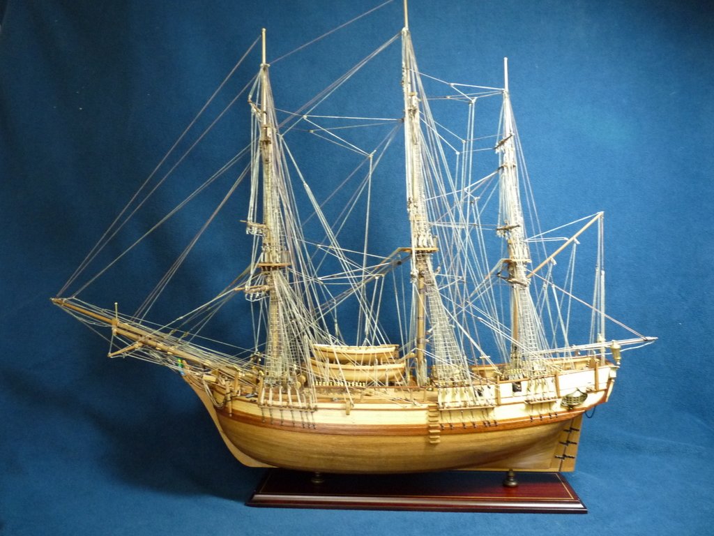

-
Correction: The button reads "Enable Content"
-
Dave, Look at the ribbon in yellow just above the "Edit Program" button. It essentially says that you can't edit the spreadsheet (yet). Hit the Enable Editing button to the right of the message, and you will be able to then use the spreadsheet. Regards, Ted
-
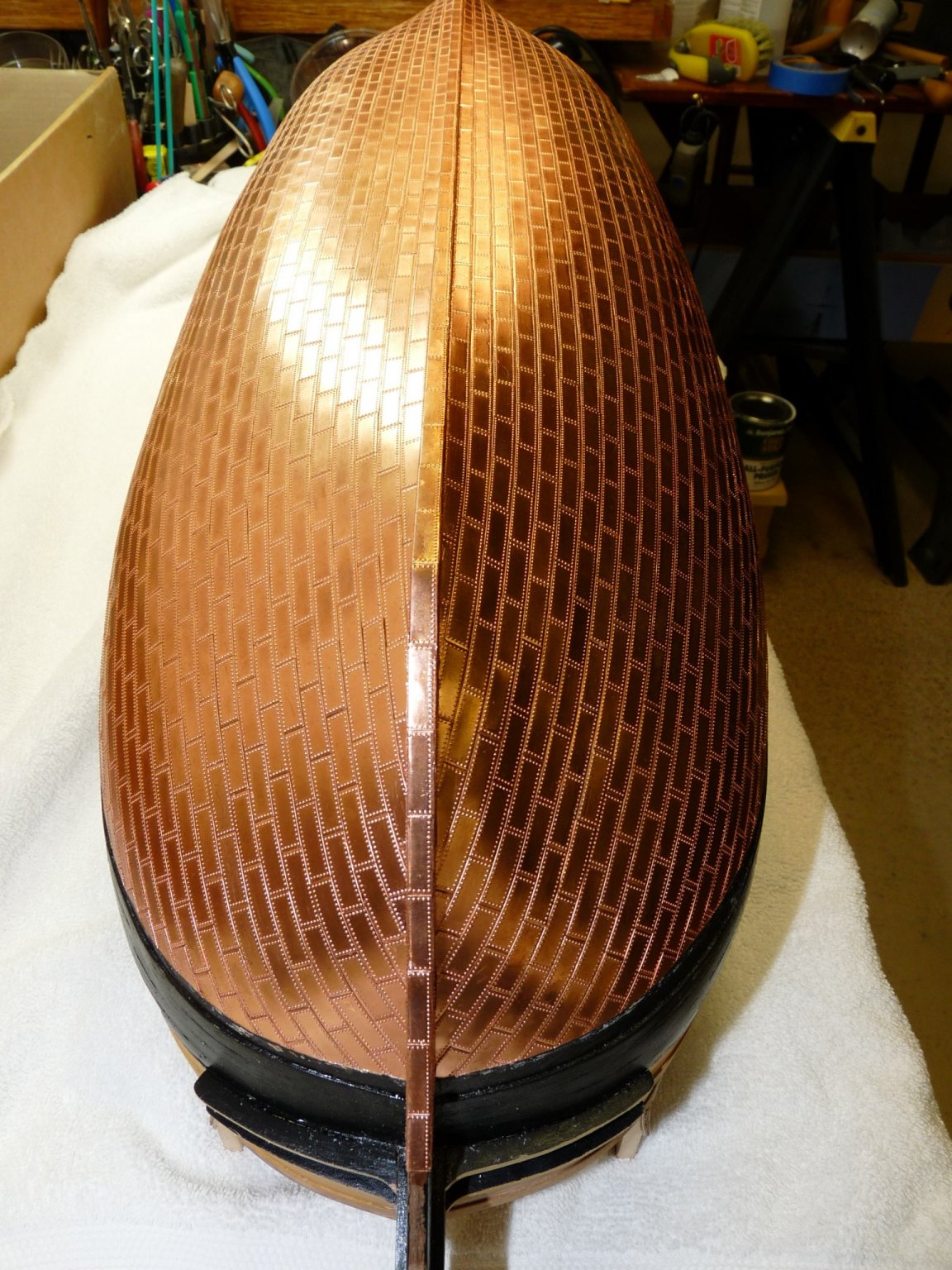
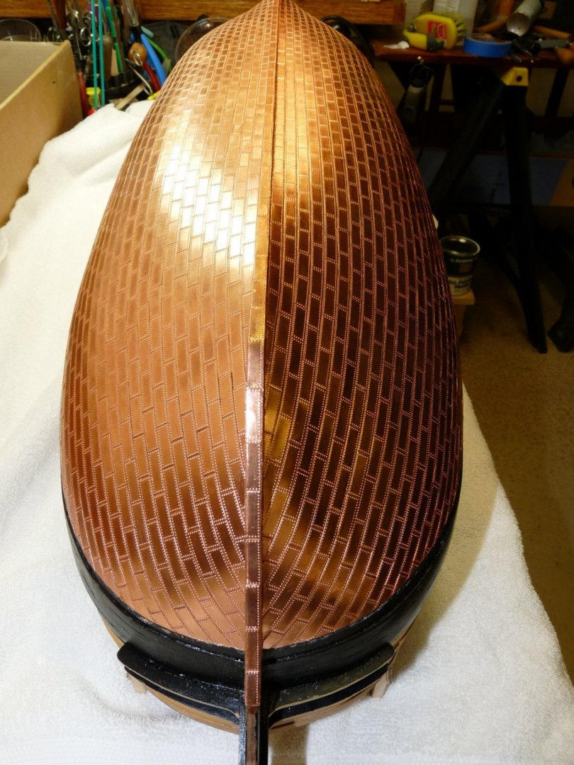
Here are a couple of before and after pictures of the plated hull. The first was when I added the plates in October 2010, the second shot id how it looks today with natural aged patina.

-
Hi Will, I did no aging or patina on my hull plates, they will just age nicely by themselves if you leave them alone. I glued mine on with (gasp!!) CA gel, using 3 or 4 small dabs/plate using a toothpick. I'm in the process of uploading a bunch of old photos of my Vic, I'll add some of the plating sometime soon.... take an occasional look at my log and you can look at the results and judge for yourself. One trick that I learned is to carefully mark the waterline before starting. Begin at the keel, working your way up to the WL. When you get to the waterline, overlap it with the plates - then run a piece of tape along the waterline and trim the copper with a sharp Exacto knife. It will leave a nice clean line, the objection being that the trimmed plates will no longer have the nail marks along their top edge. I agree with others that you should test the application on a test piece, but you should be OK.. just make sure that the hull surface is clean and dry, and don't use up many plates in the testing process; I only had a few dozen left over after the plating job. Remember that the rudder needs plating as well. Ted.
-
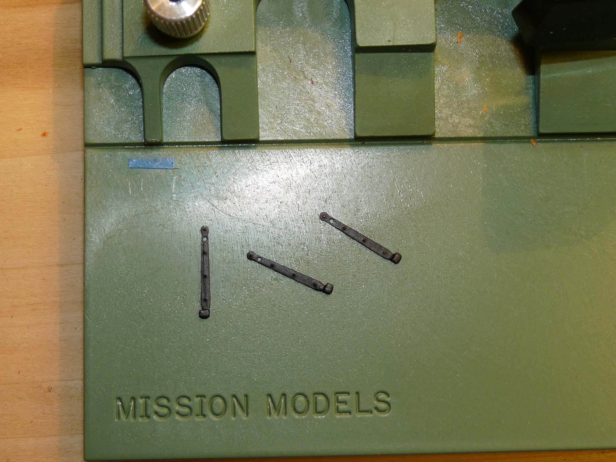
The hinges were just painted. They get dinged up with handling and installing, so small touch-up with black Jotika paint after will make them look fine.
-
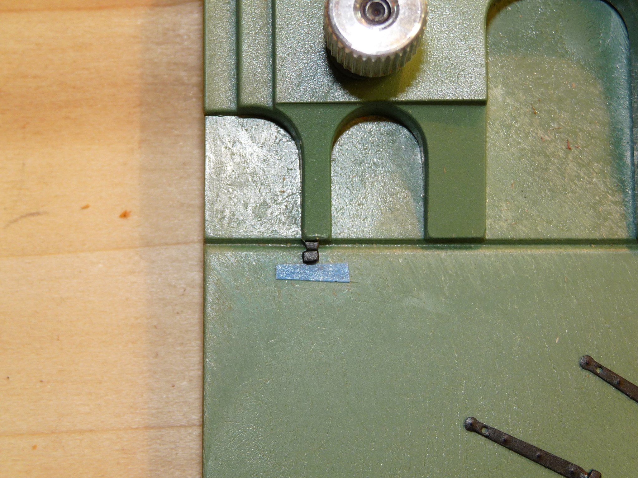
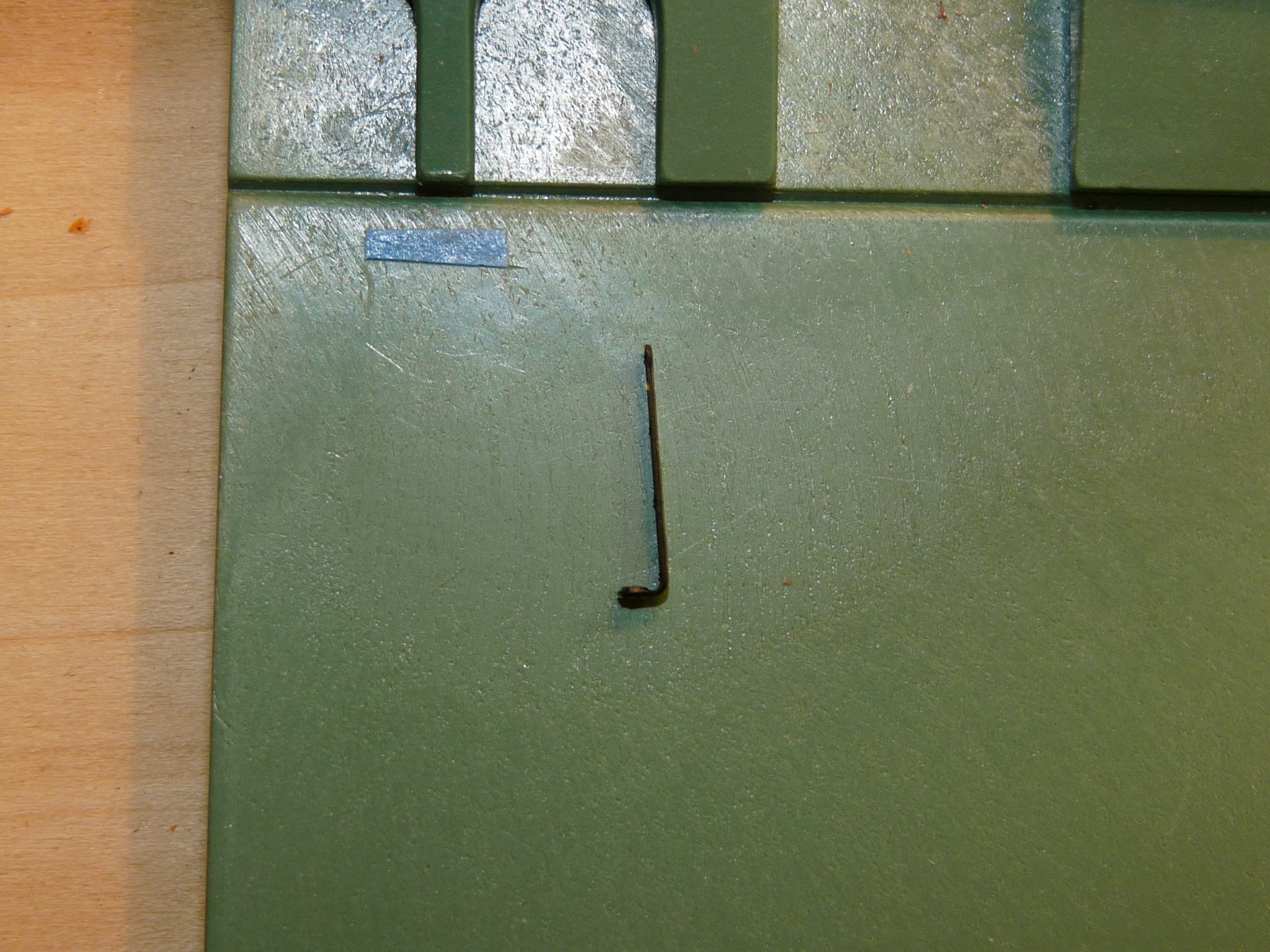
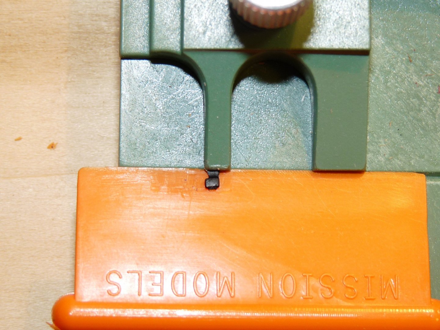
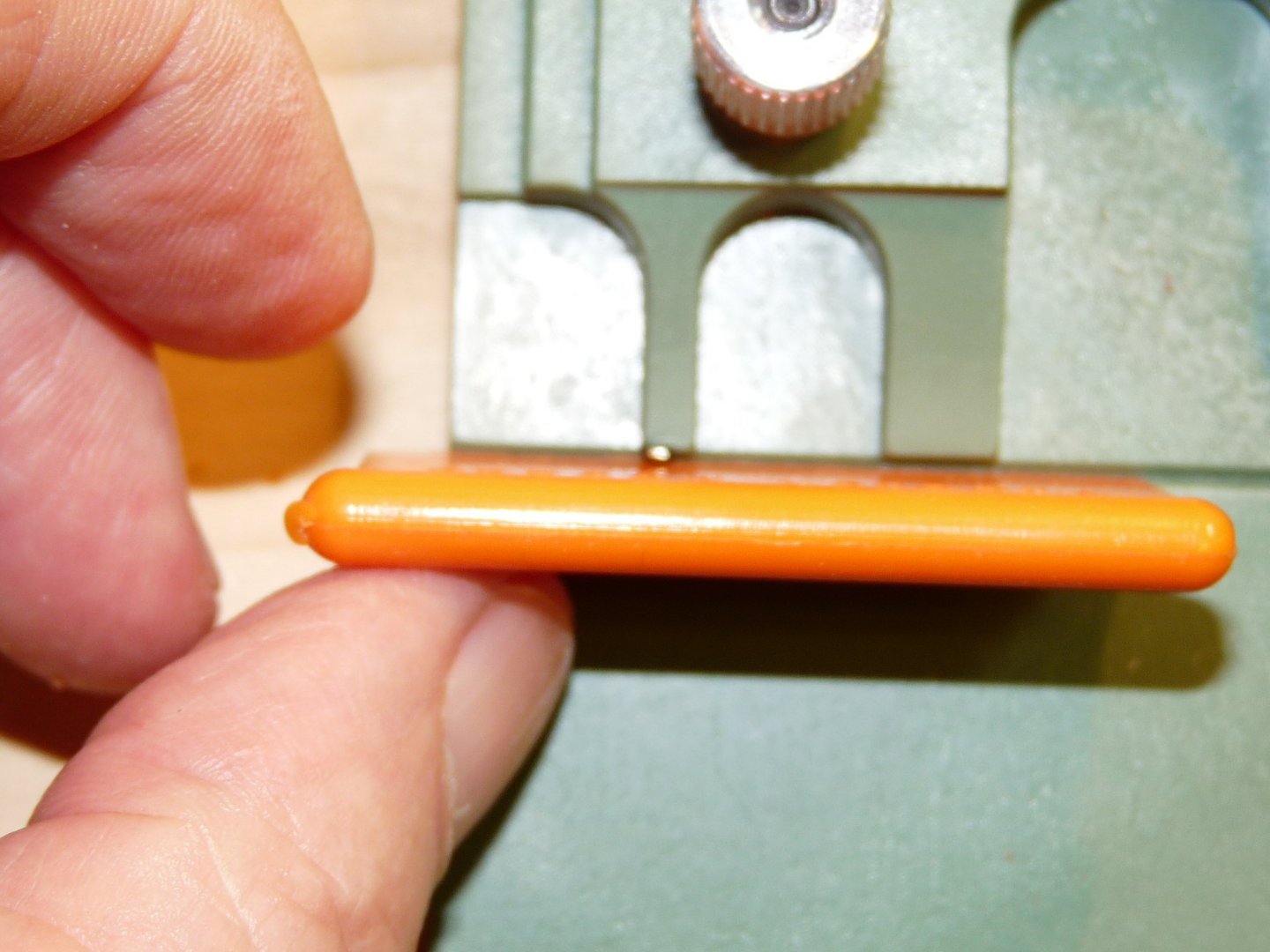
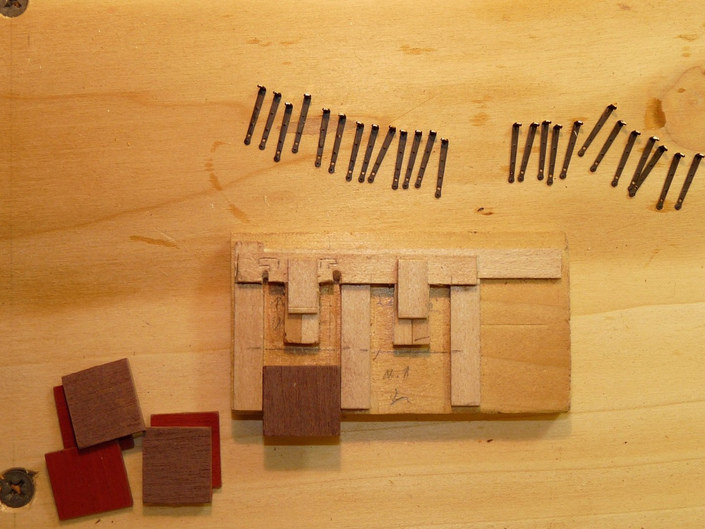
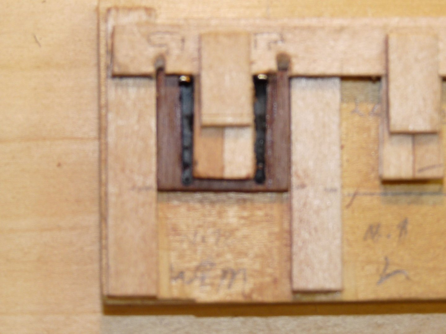
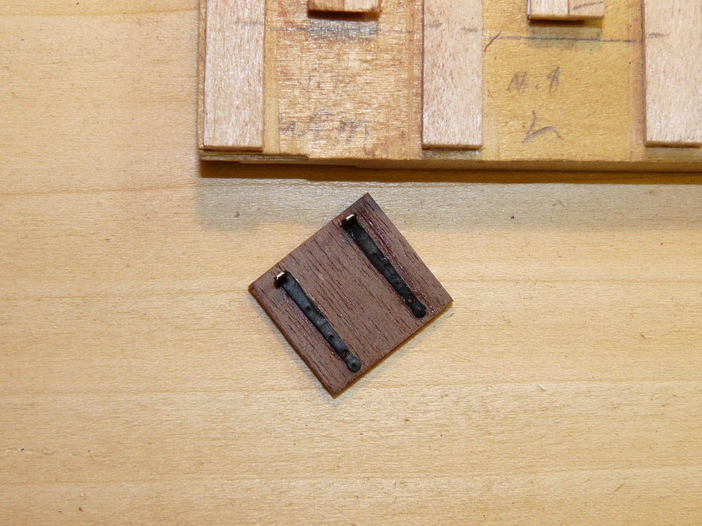
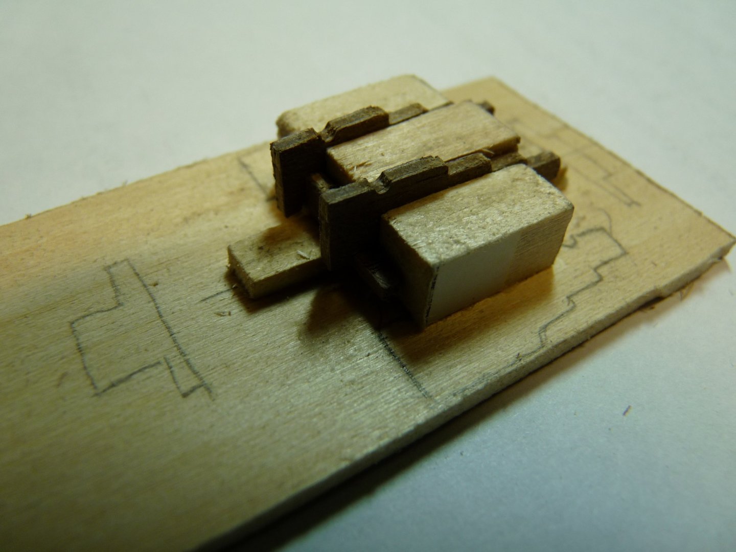
Somewhere along the line one has to tackle the assembly and installation of the gunport lids. After they are painted, the hinges have to be added. For those ports shown in the open position, the hinges have to be bent to about 90 degrees. This can be tricky on these tiny photoetched parts. In my bag of tricks I had a Mission Models Etchmate 3C, a tool designed expressly for bending small photoetched brass parts. It is a little pricey at $60, but if you do a lot of this work it is worthwhile. I bought mine a decade or more ago, and a quick look online indicates that they are no longer available; perhaps Mission Models no longer makes this item, but it seems that one can find them on eBay for about $30. Here are some photos of the 3C bending hinges, and some simple jigs to locate them.


-
Hi Dave, I am running Windows 10, and the downloaded spreadsheet shows up as an Excel file. When it is opened, it comes up as a protected file which can't be edited to input your particular data. At the top of the page is a button to Enable editing. Click on that, then hit the salmon "New Build" button to clear the spreadsheet of previous data, if any. Then enter your scale factor in the pink box at lower left, and then the green "enter Data" button to get started.
-
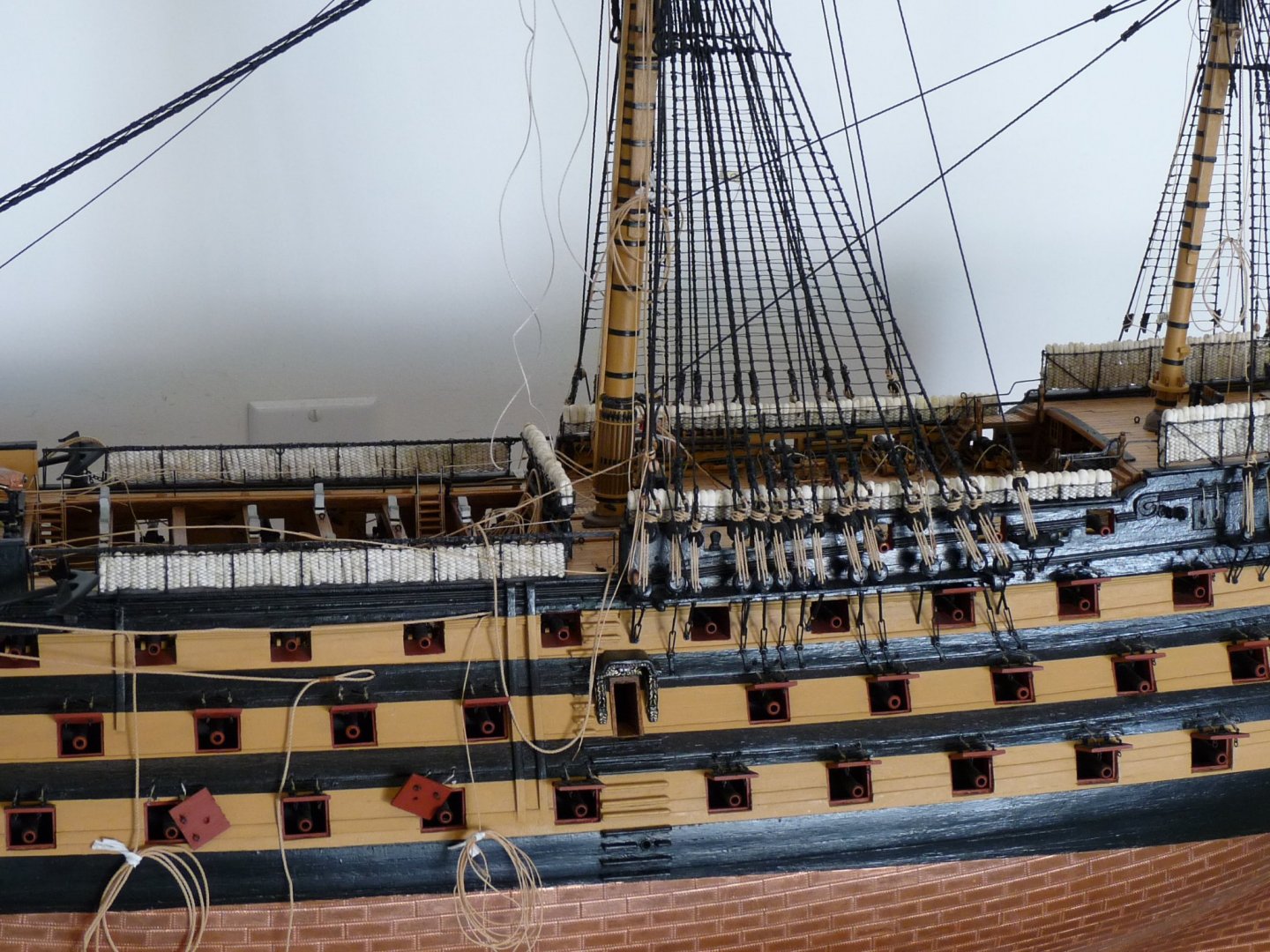
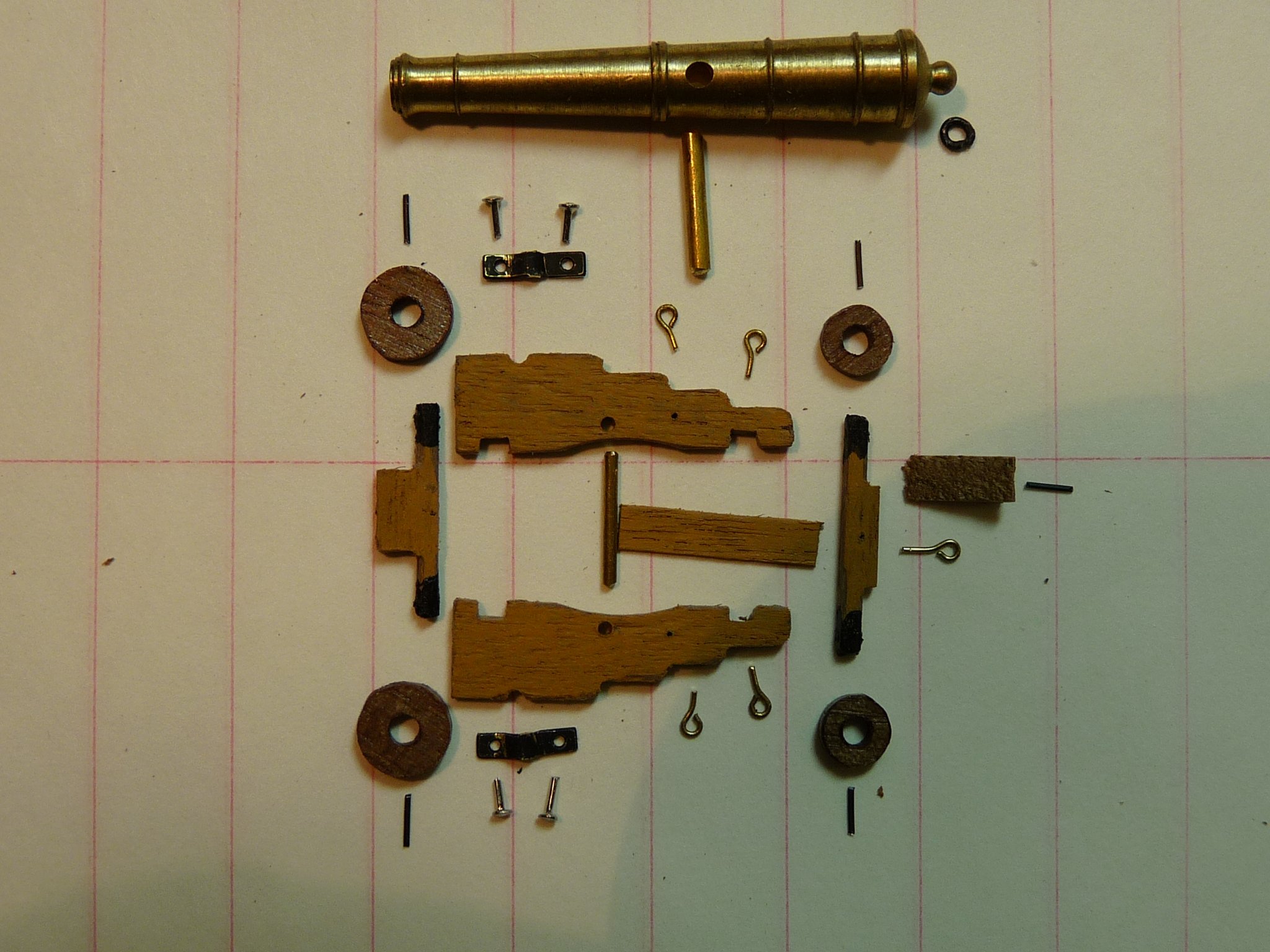
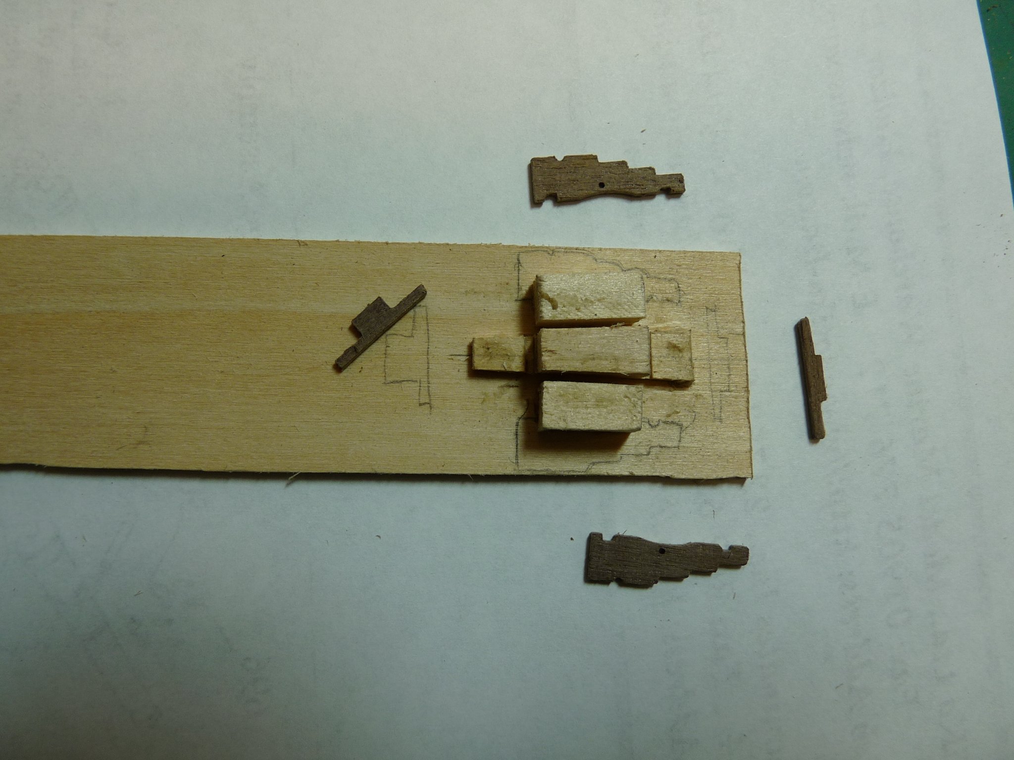
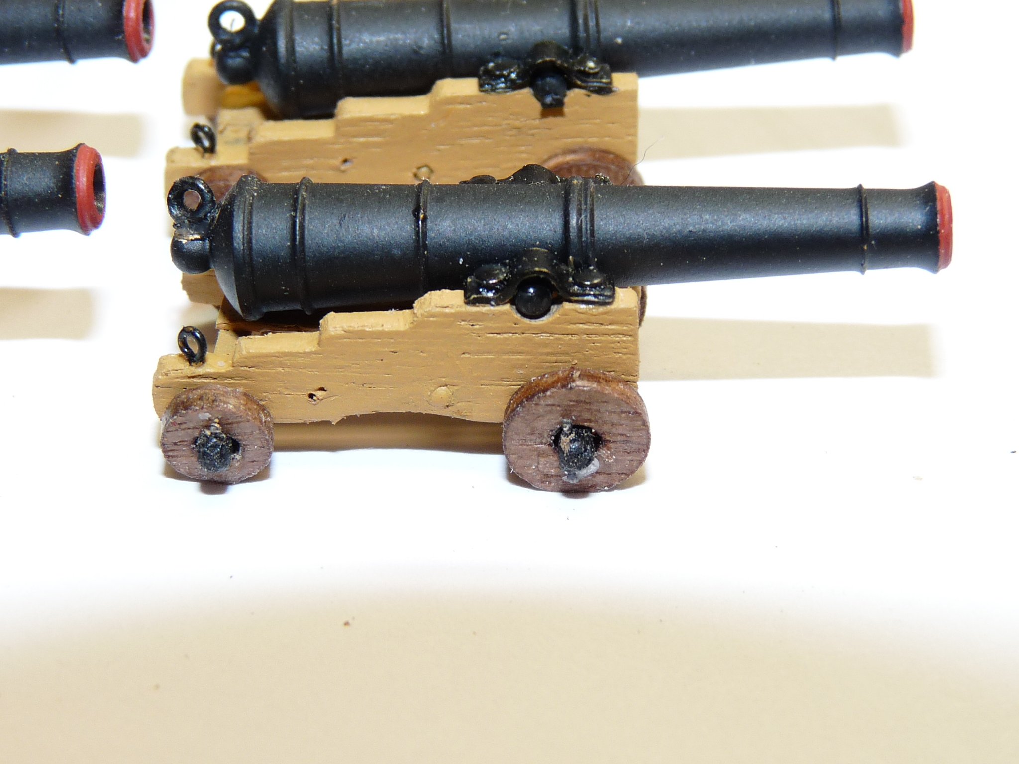
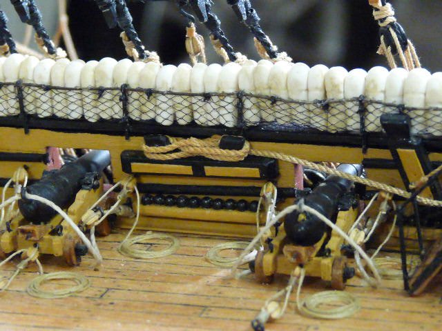
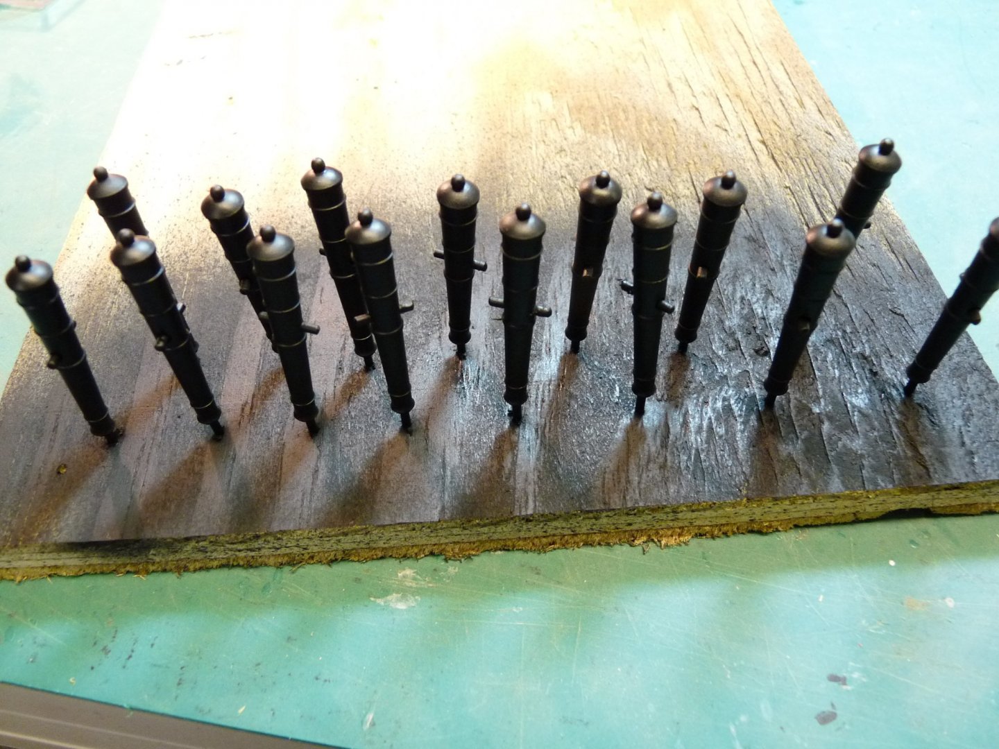
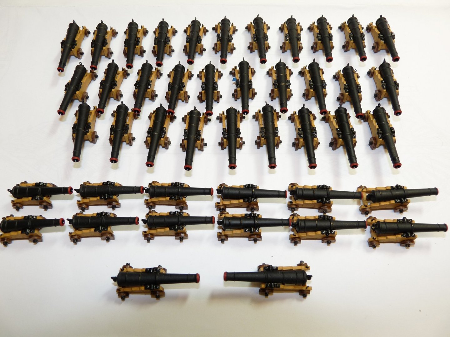
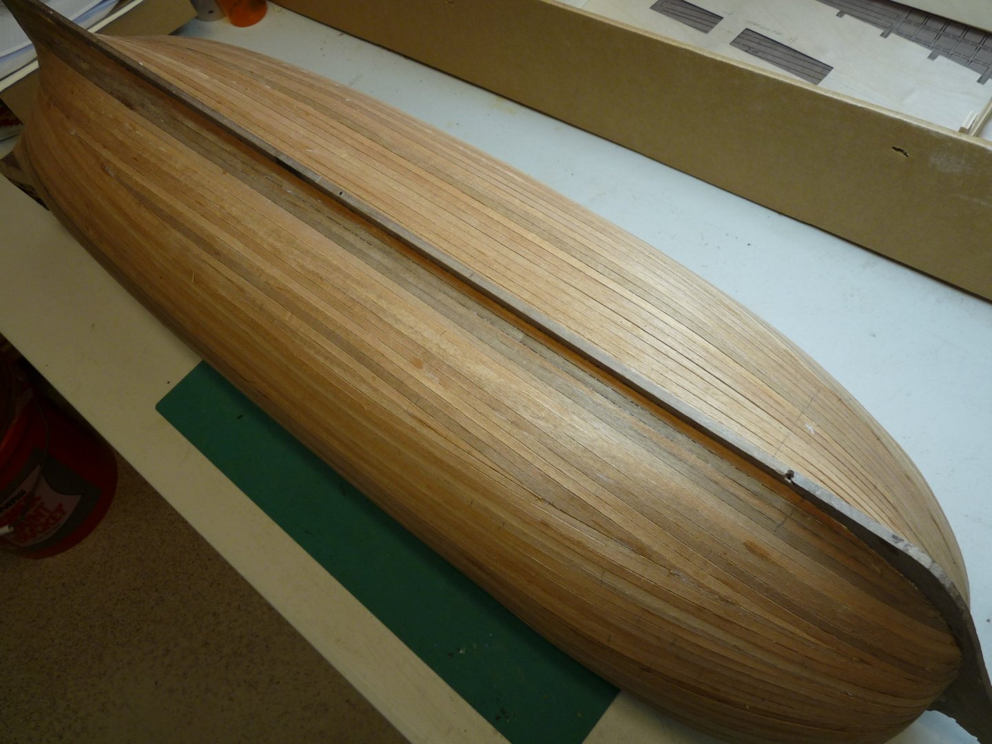
Hi Will, I posted a reply on your build log explaining exactly how I did my planks. Hope it was clear; if not get back to me with any questions. Cannon barrels were simply well cleaned and spray painted with flat black Krylon. I probably overdid it in making the carriages with axel pins and quoin handles, since only a few of the finished guns will be visible in the final analysis. These closeup photos show all the flaws - dust, open wood grain etc. Could have done a better job! I'll be posting more pix on my build here in the next few days. As I said yesterday, these shots were taken over 10 years ago during the early stages of my build. I am now in the throes of completion, adding sails and running rigging as I go along. Would love to be of any help that I can be with your build. BTW, have you checked out Gil Middleton's Victory model of a few years ago?. It's somewhere here on MSW. His Vic was an inspiration for me, and as far as I am concerned is the gold standard!
-
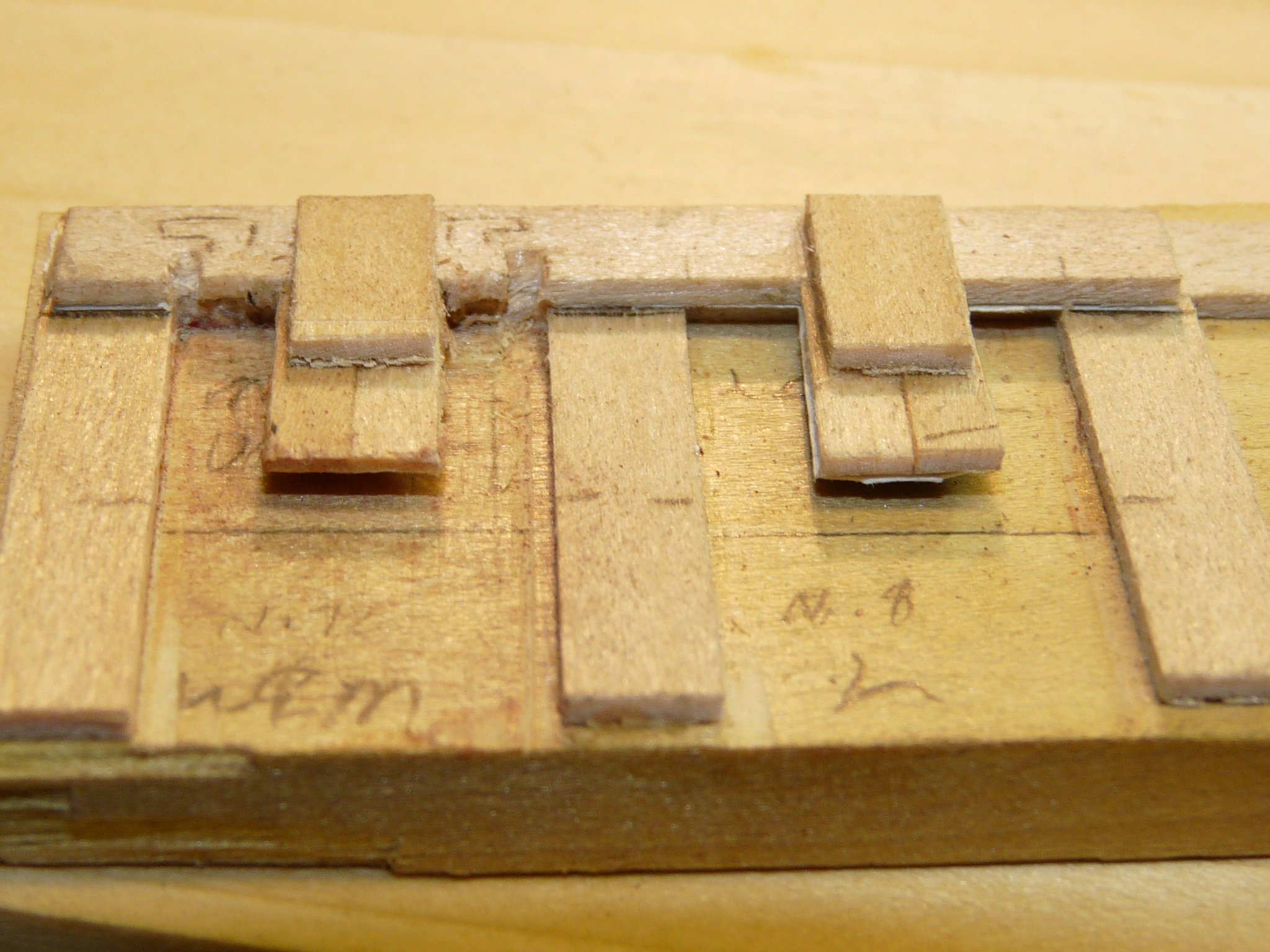
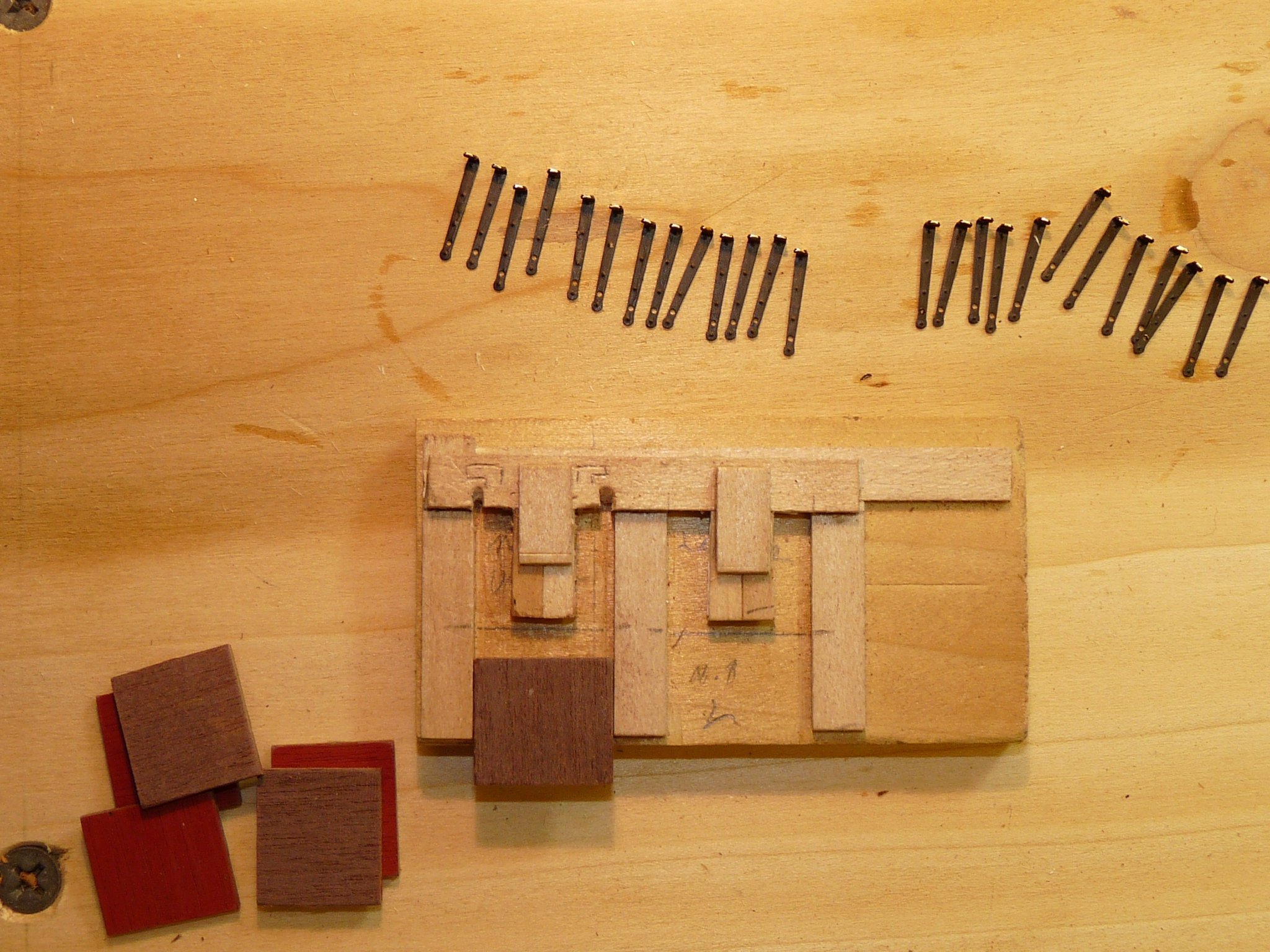
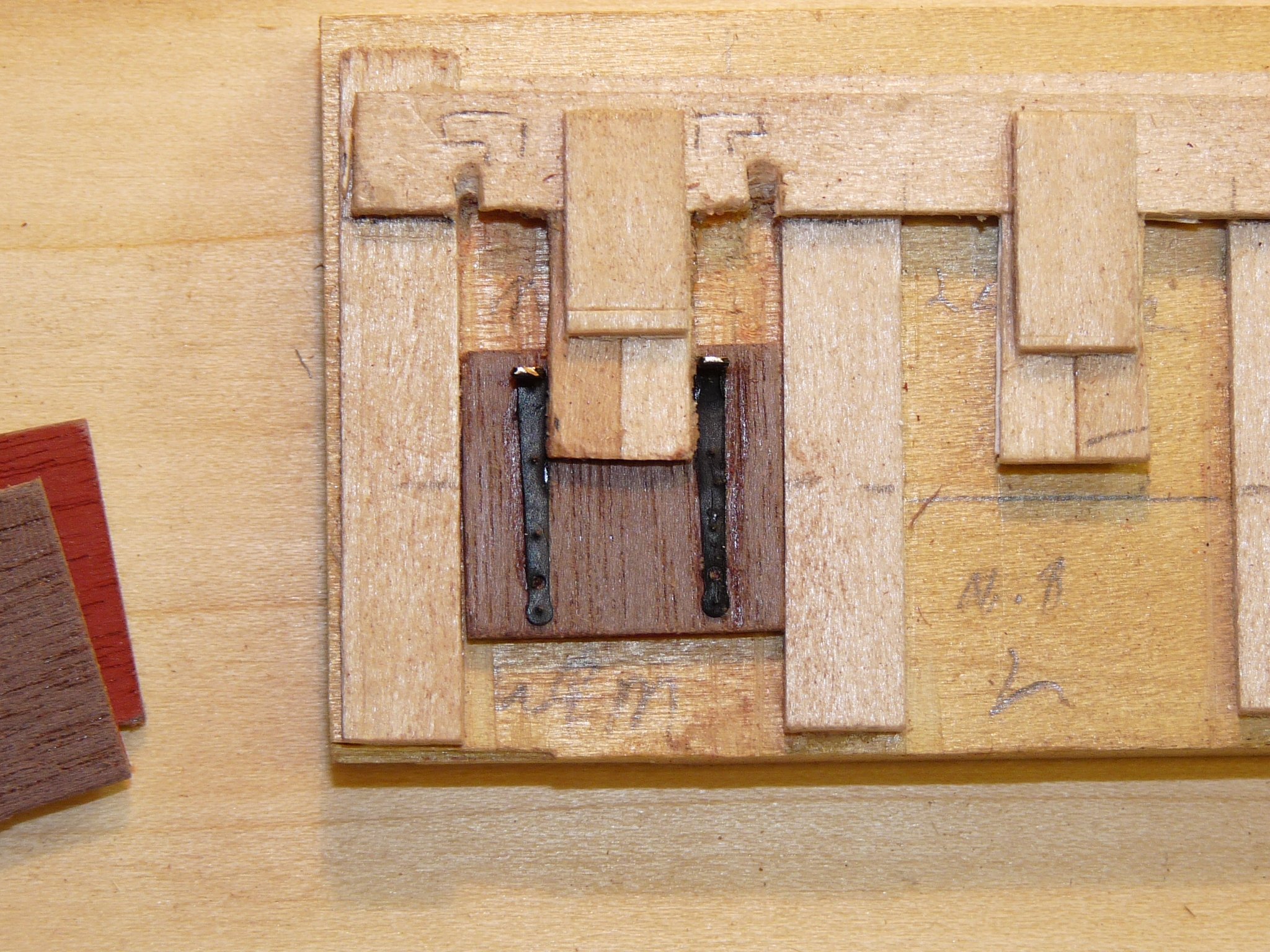
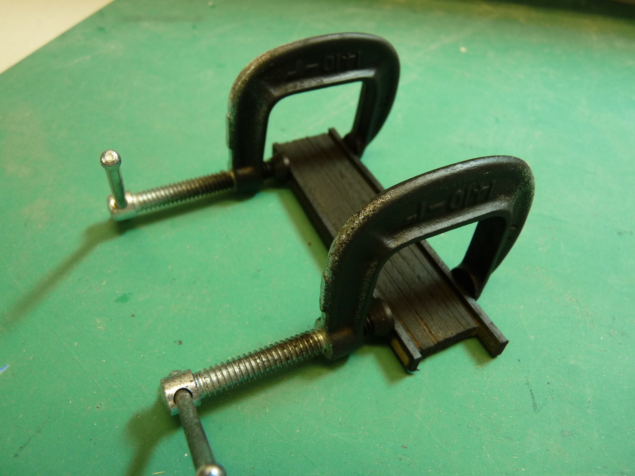
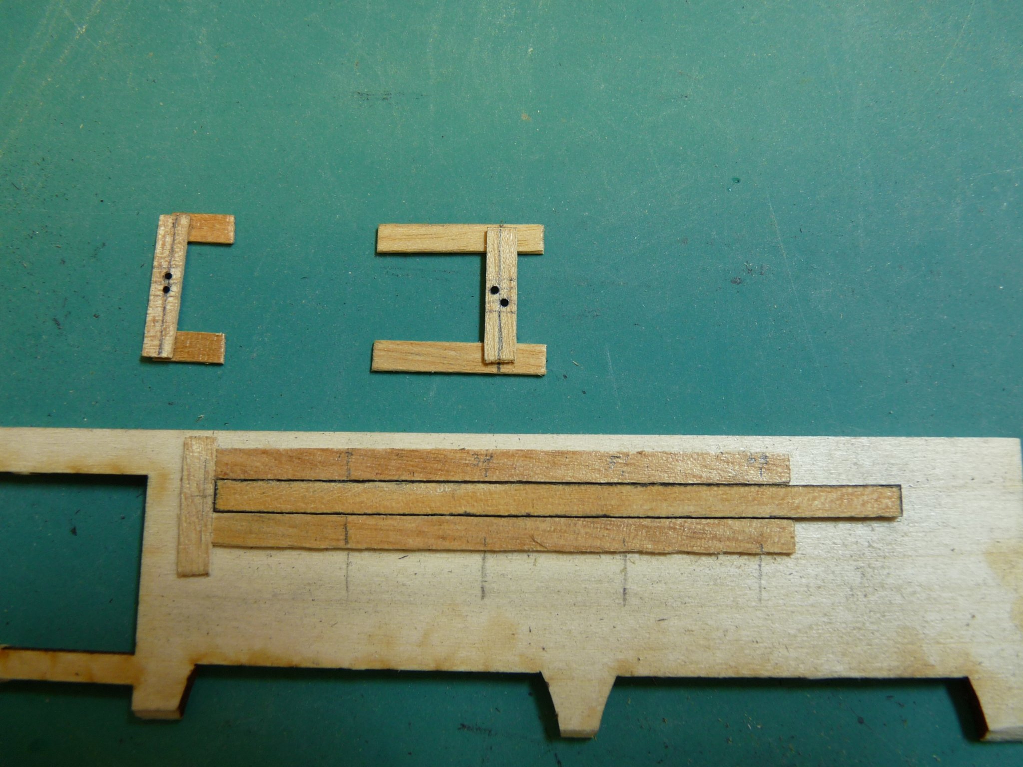
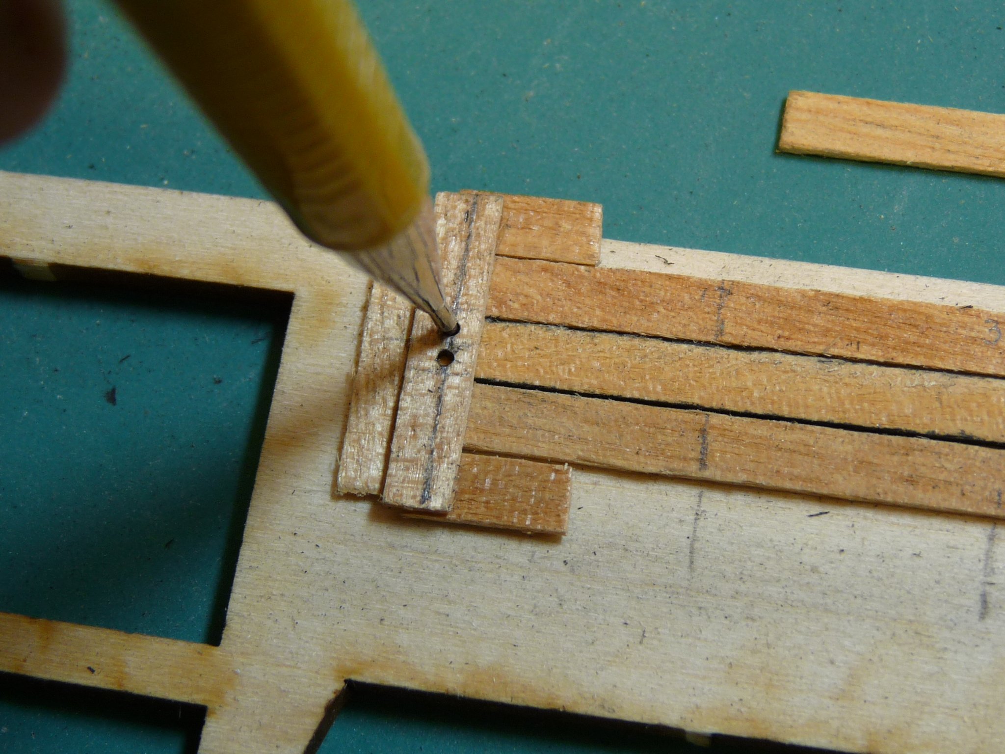
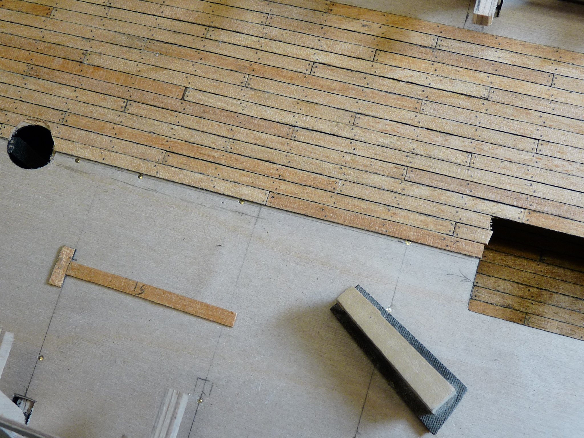
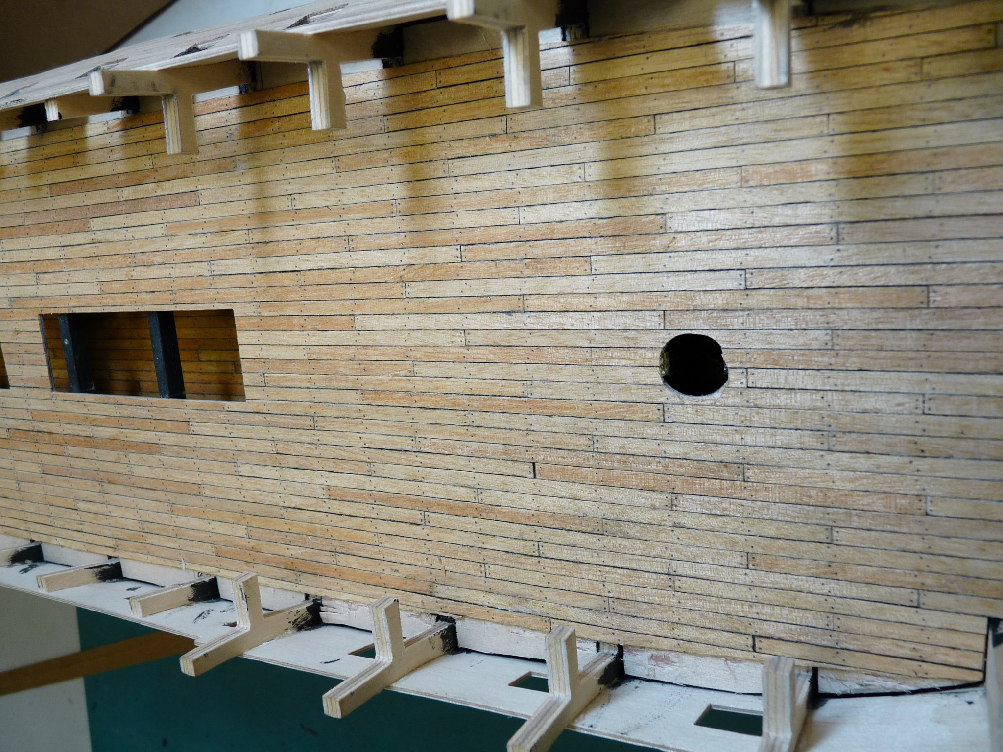
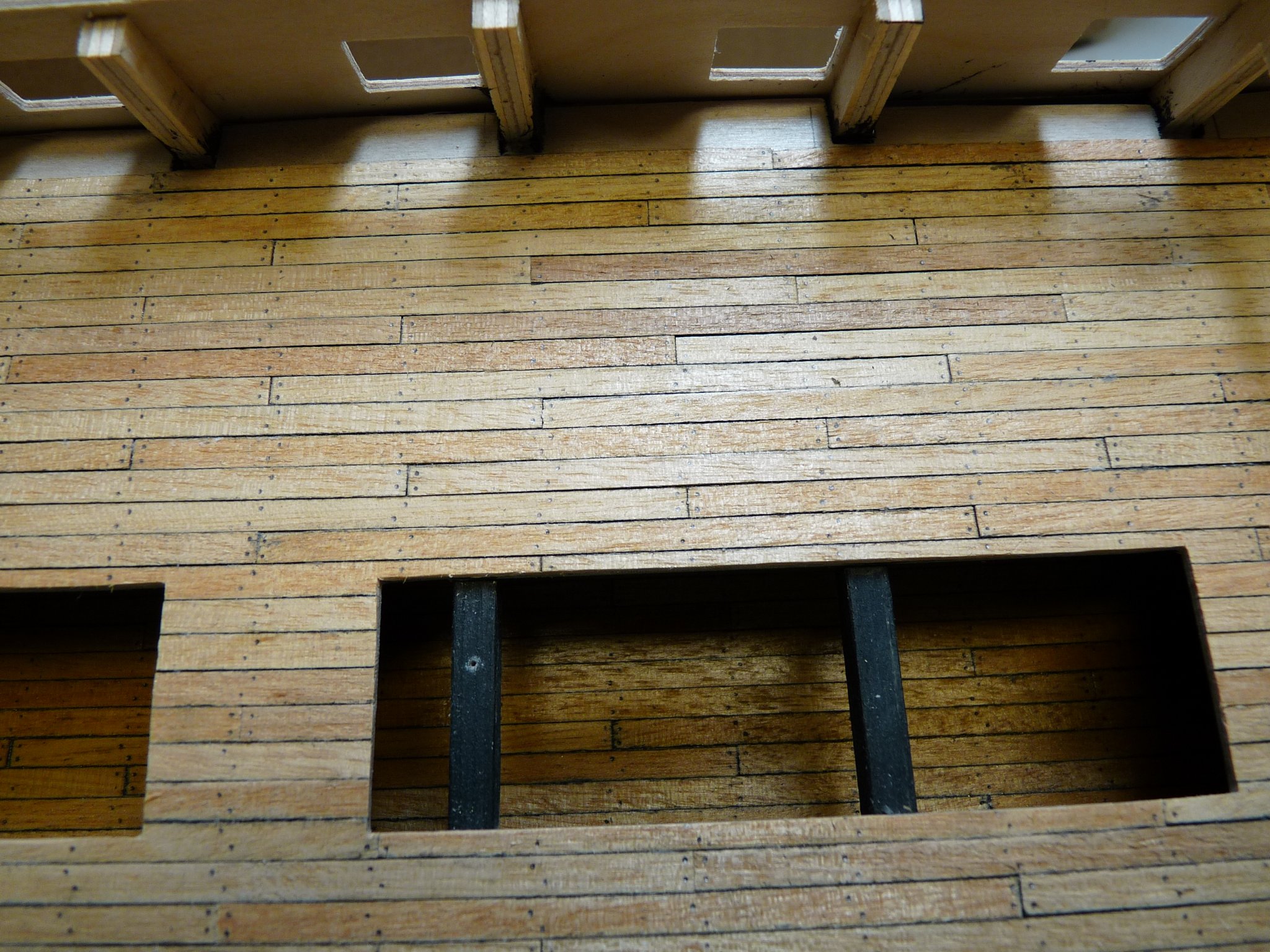
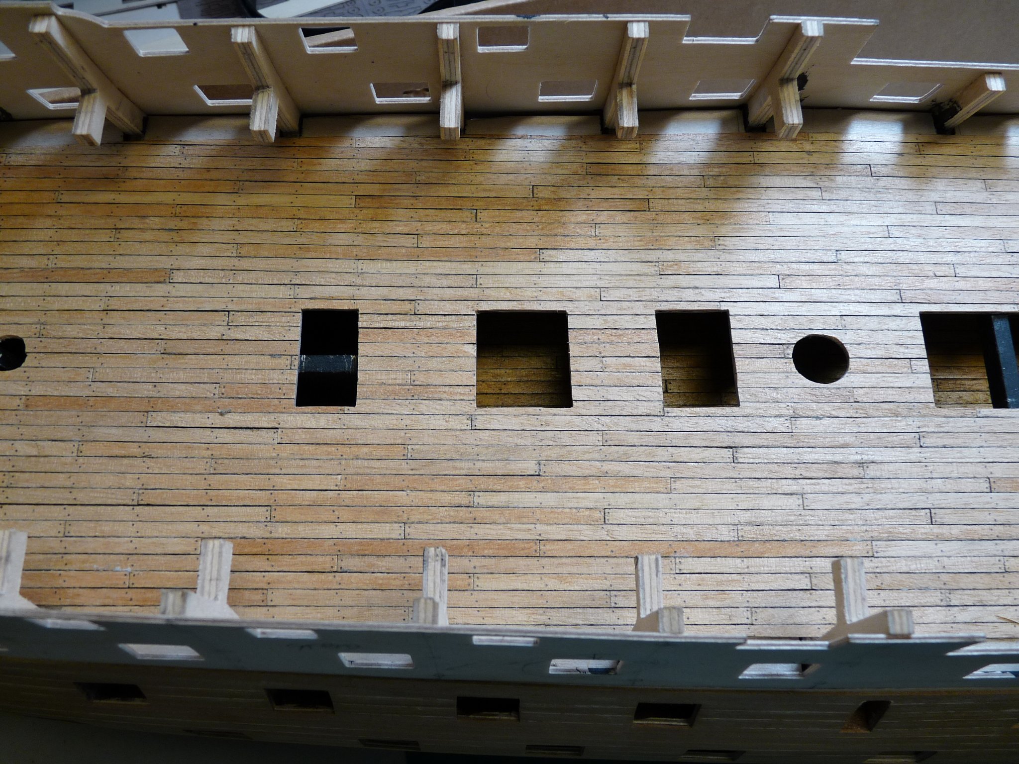
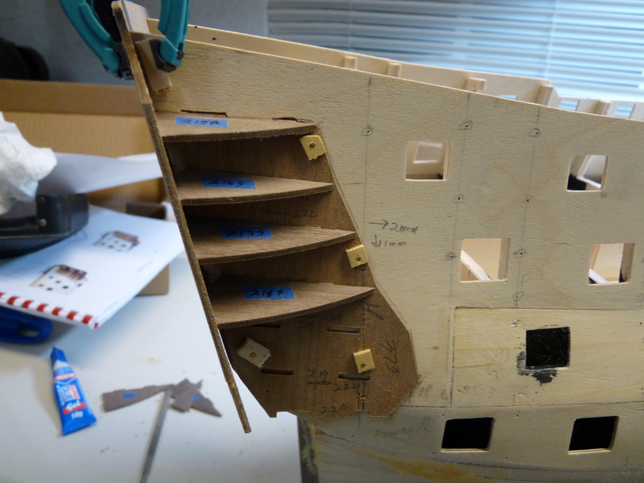
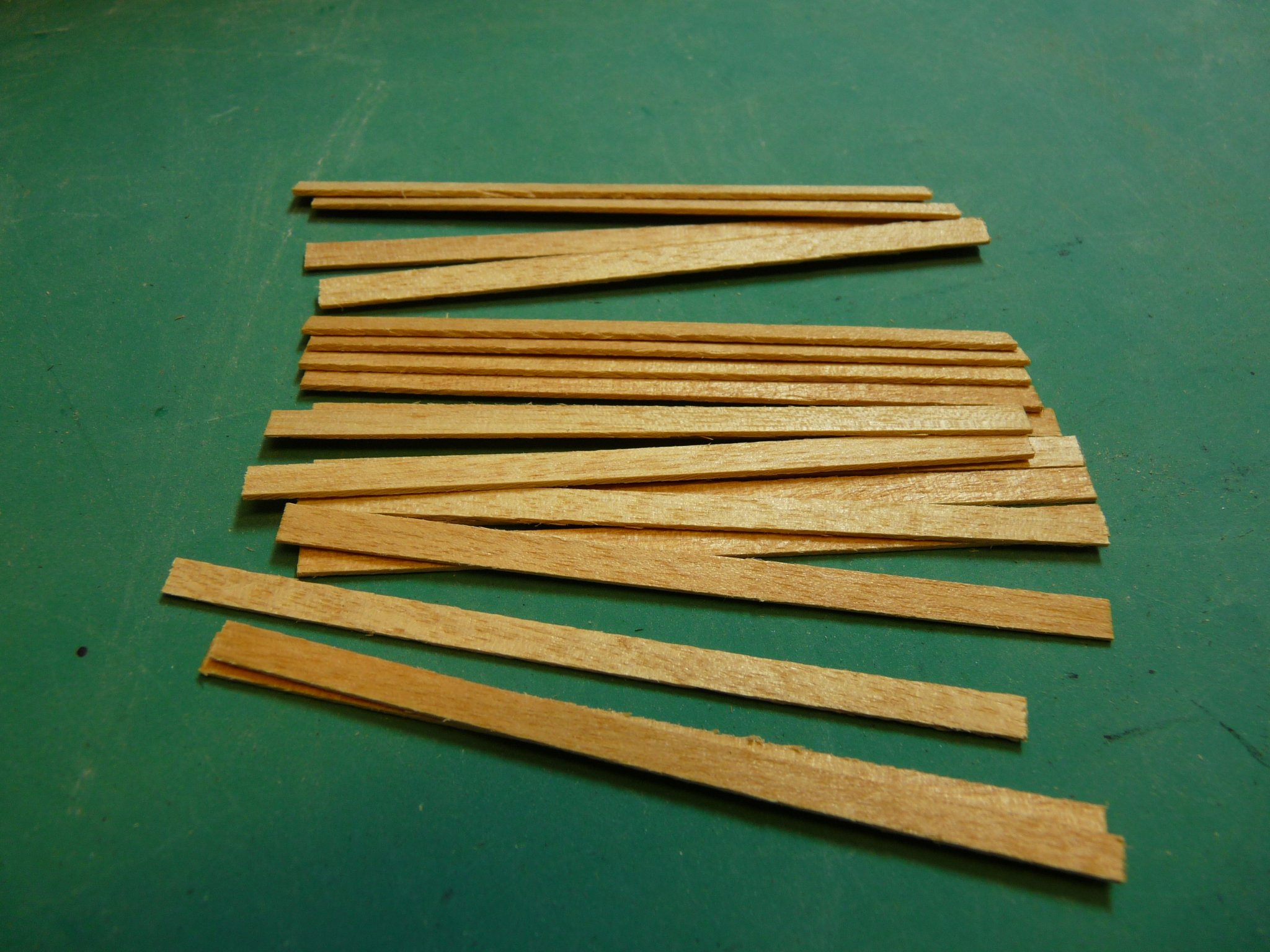
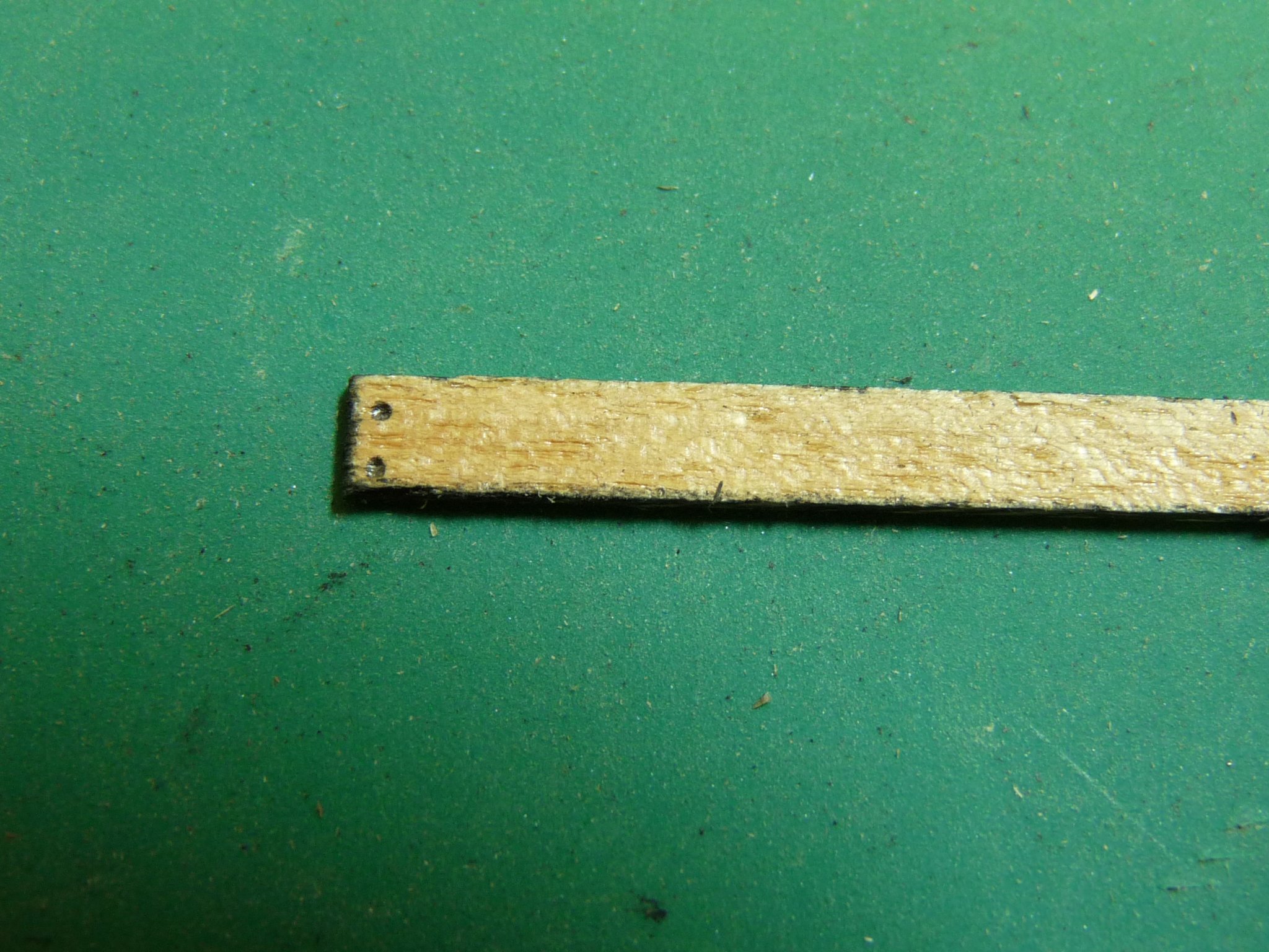
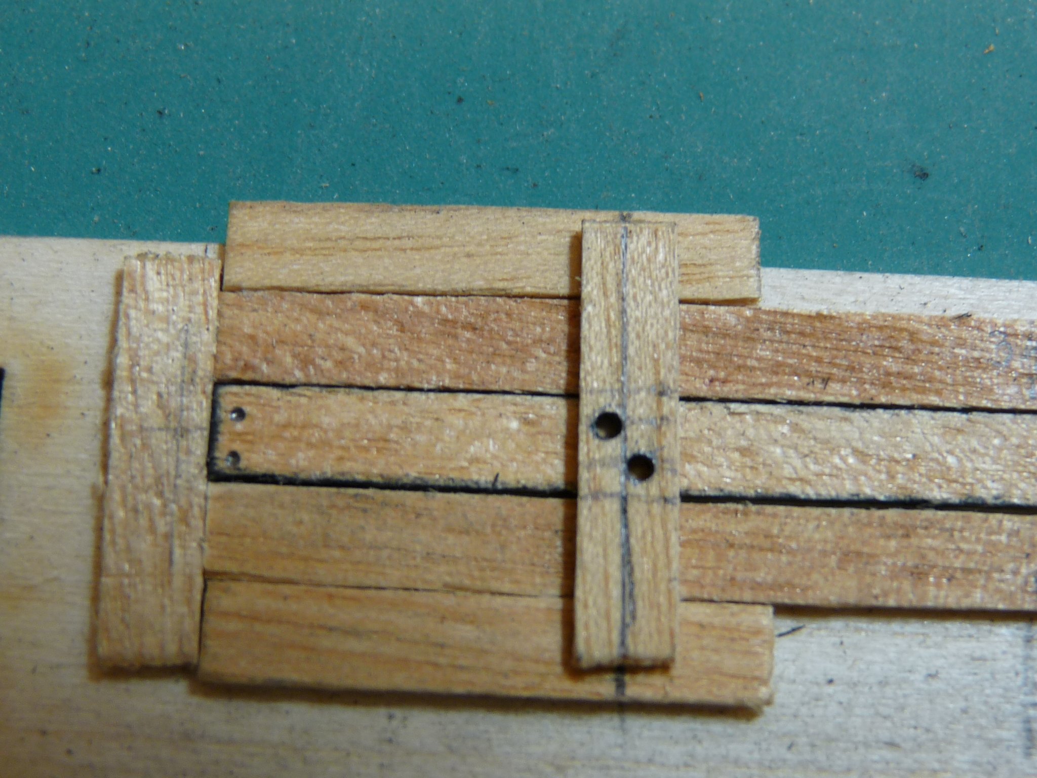
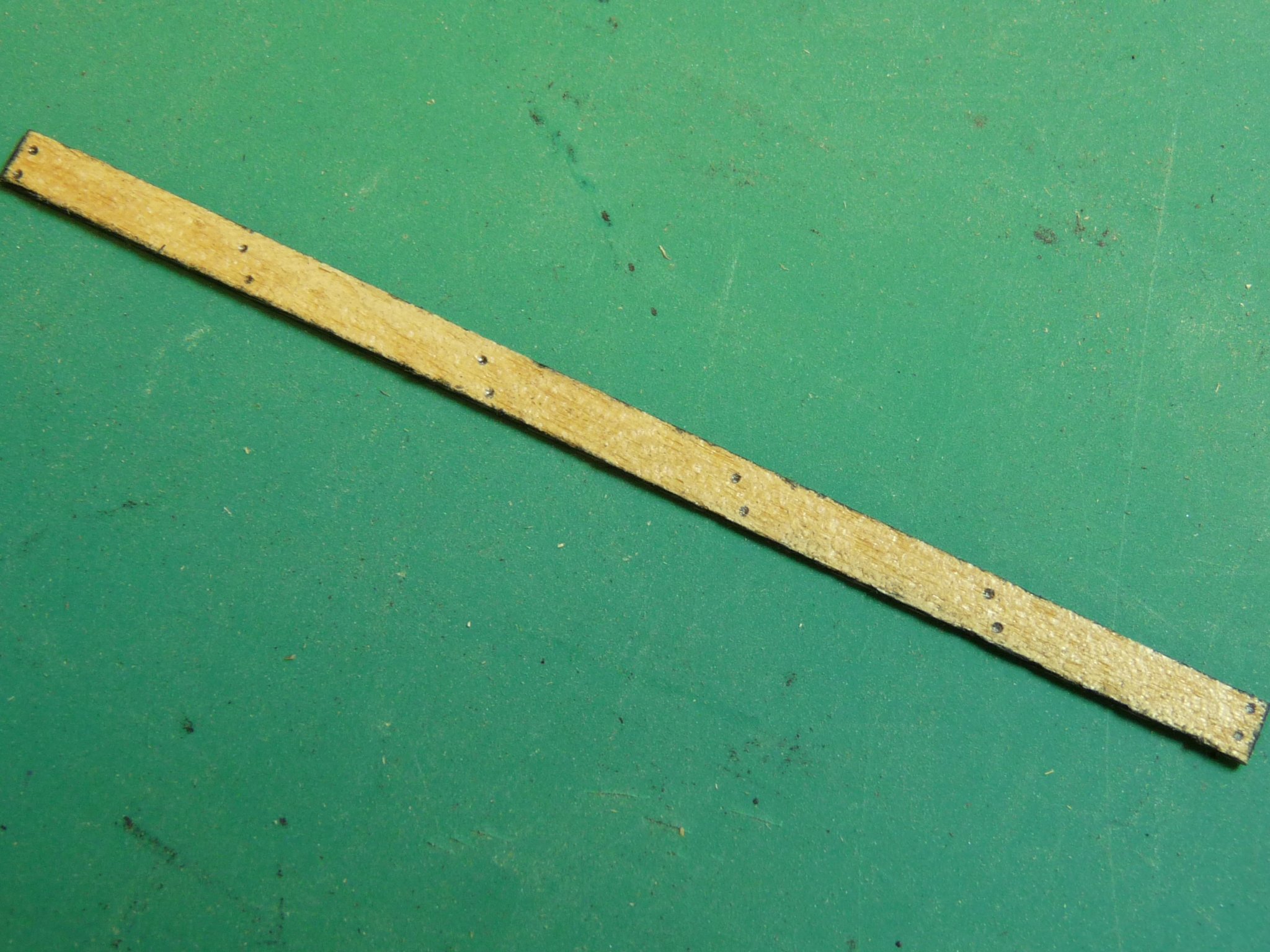
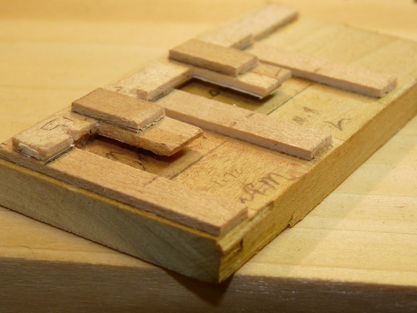
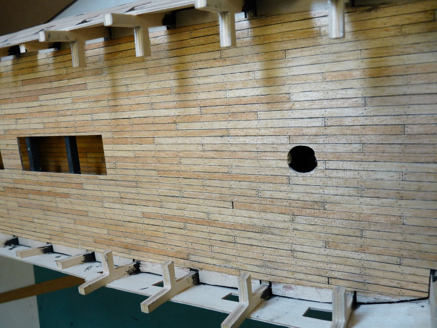
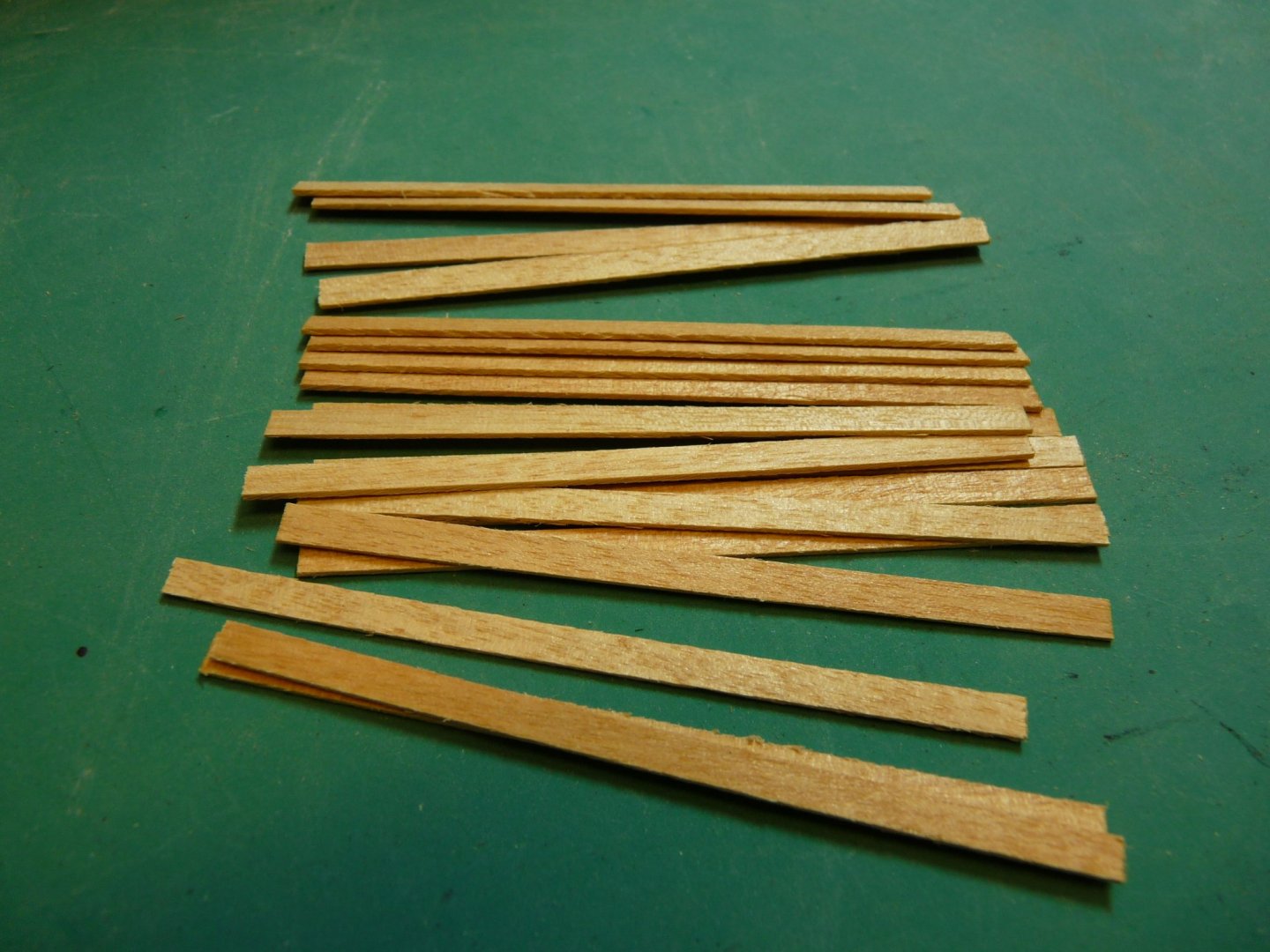
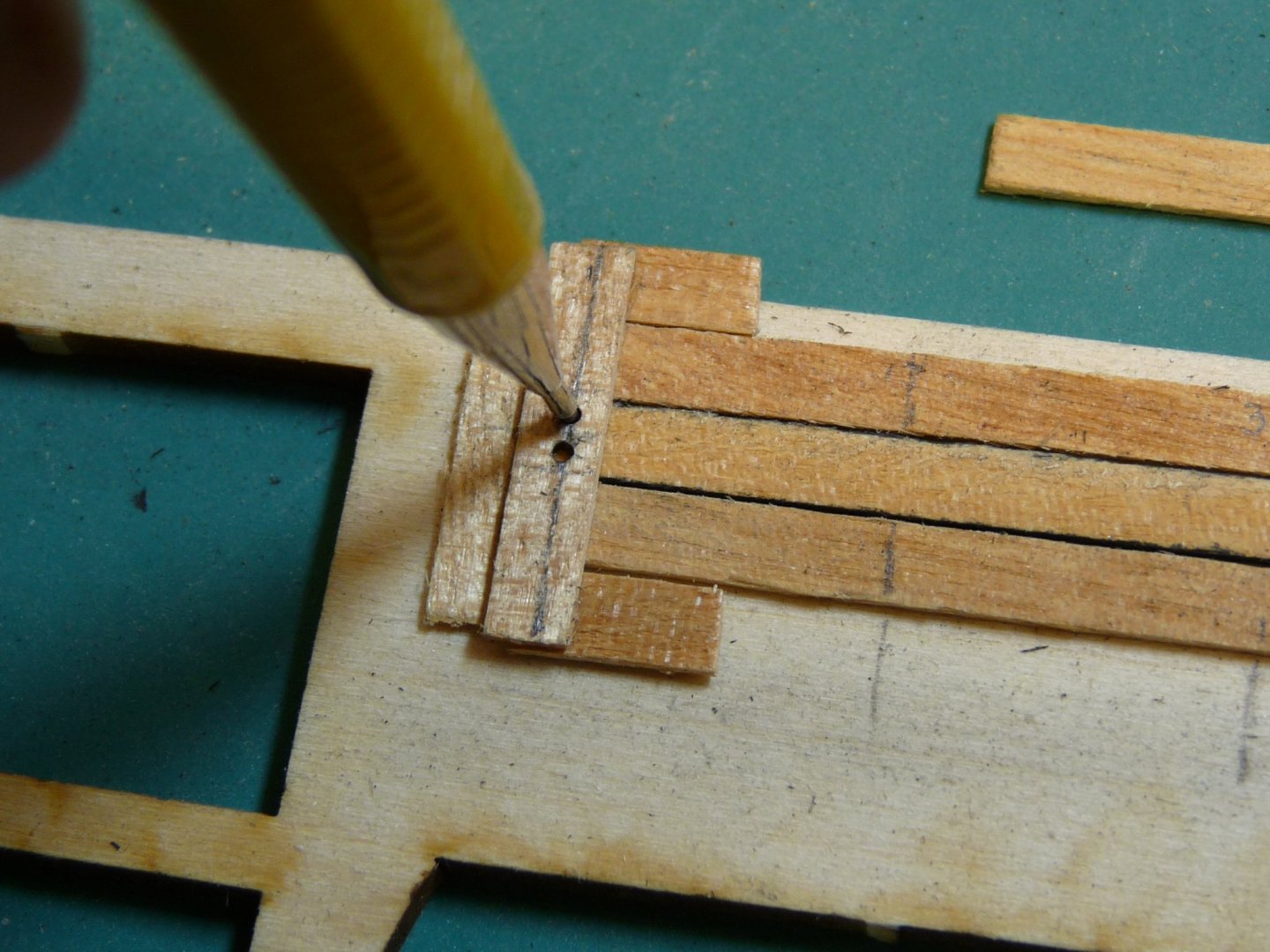
Hi Will, Here's how I did it for my Victory: Cut planks to length, sandwich about 20 of them together between stiffening pieces and clamp together. Lightly spray paint edges and ends with flat black. Remove from stack and lightly sand edges and faces to remove overspray and to lighten the dark paint. I made a jig that holds the individual planks, and two sliding templates (one for the end pattern, and another for the middle pattern of trunnels). Use a small pencil to simulate the trunnels (I didn't want them too dark). After gluing in place, sometimes the planks are uneven in height. I broke off the last couple of inches of an old mill bastard file and epoxied a small handle to it (see last photo). This is used as a small plane to even out the tops of the planks after installation. Some trunnels may need to be redone after planing. Regards, Ted


-
Gun carriage assembly jig.


-
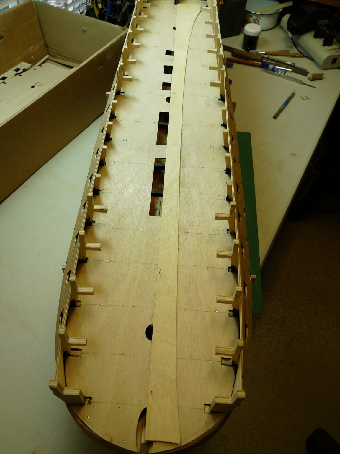
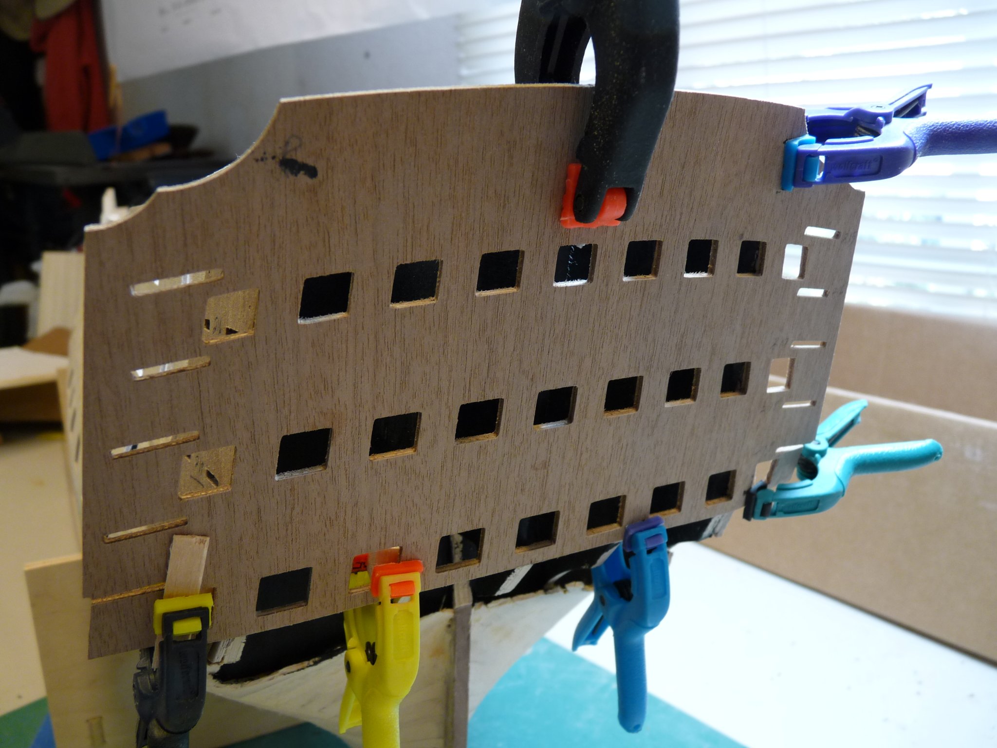
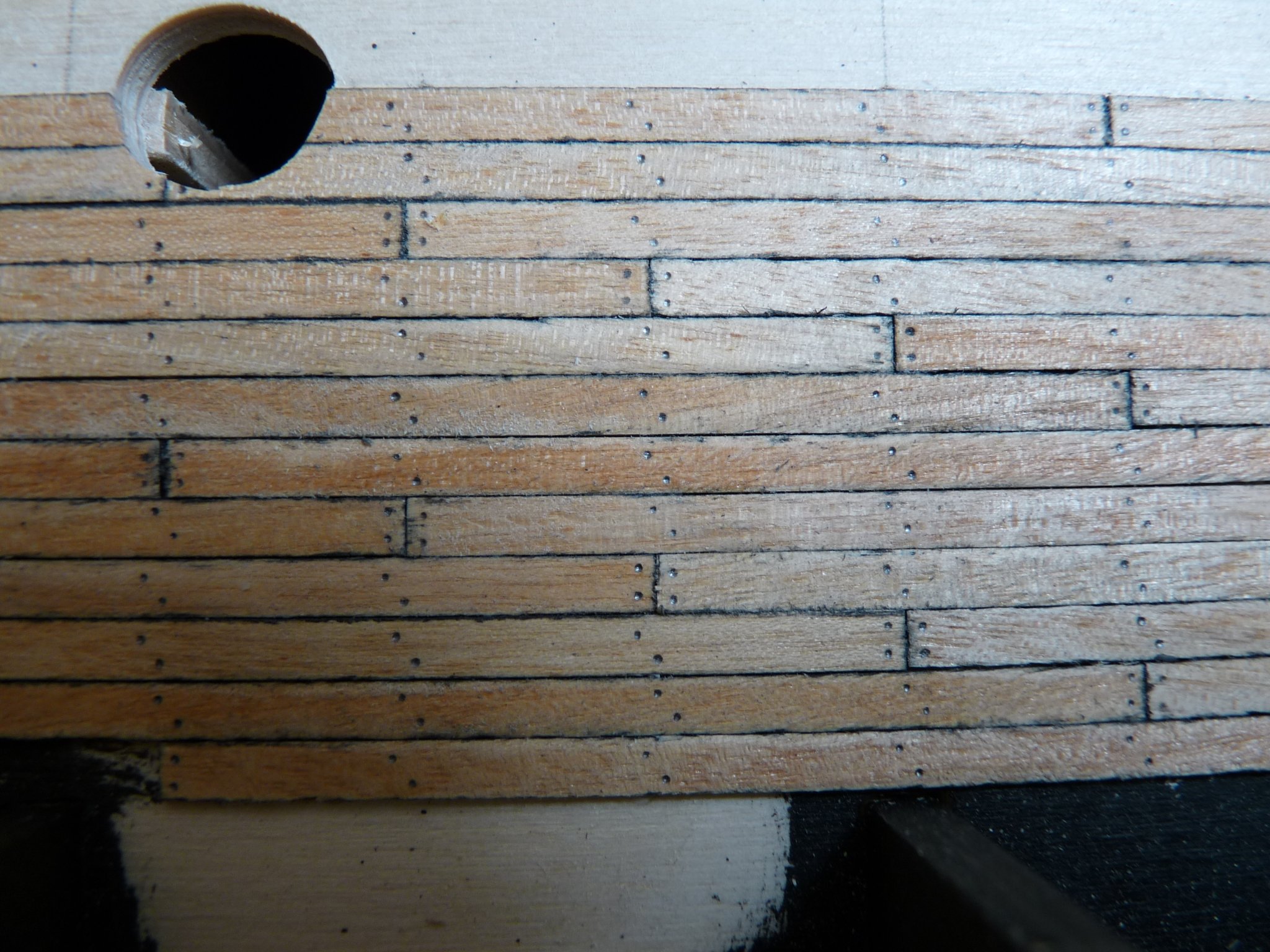
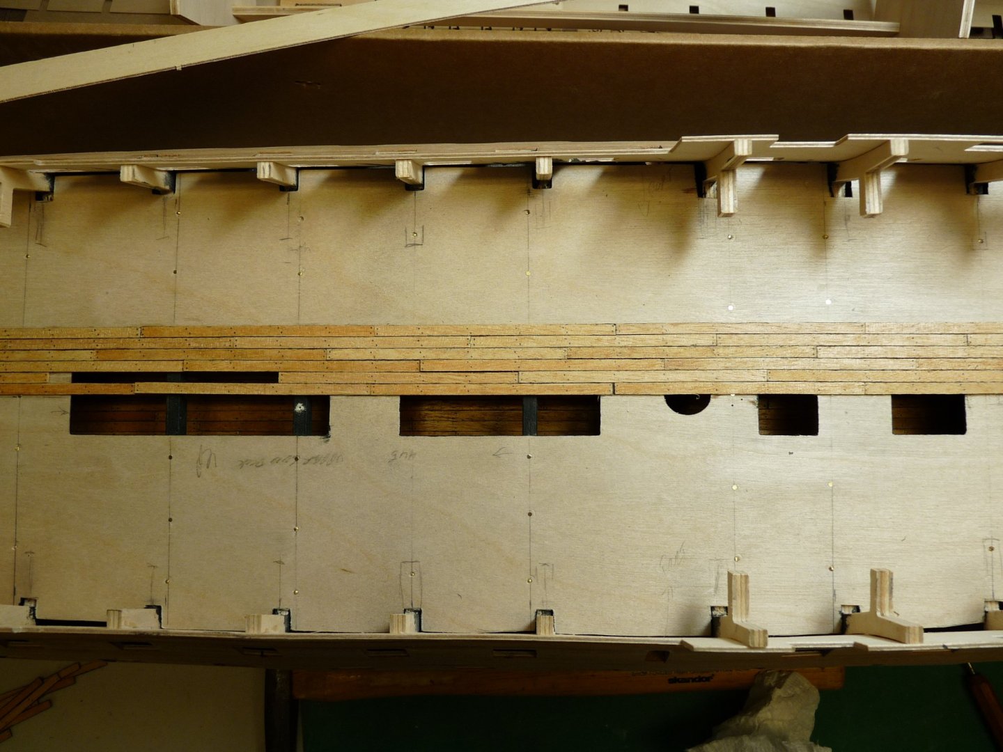
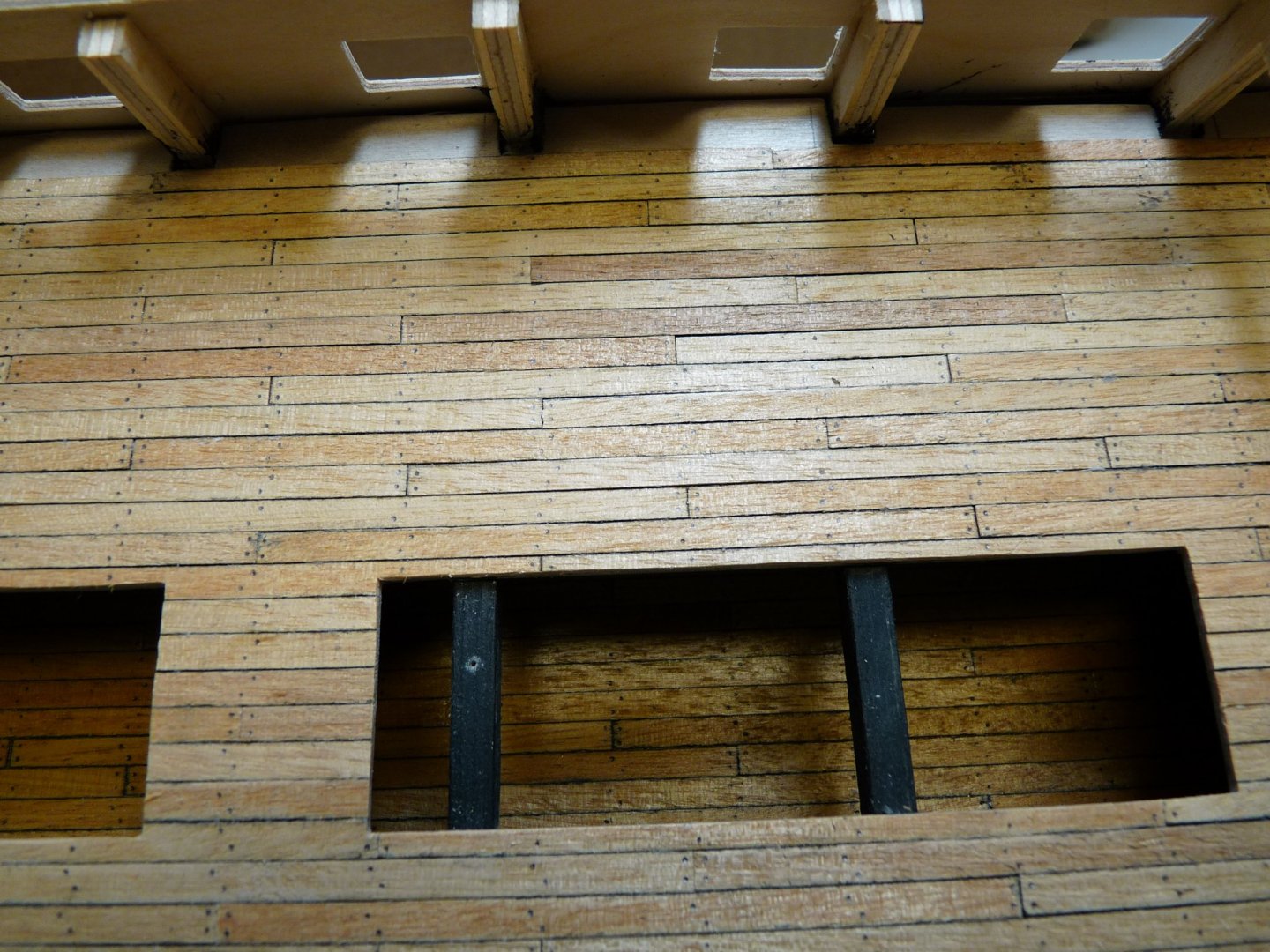
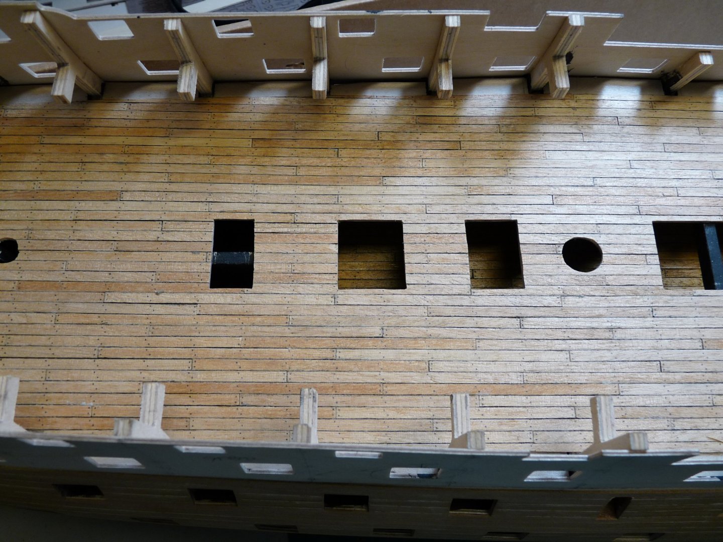
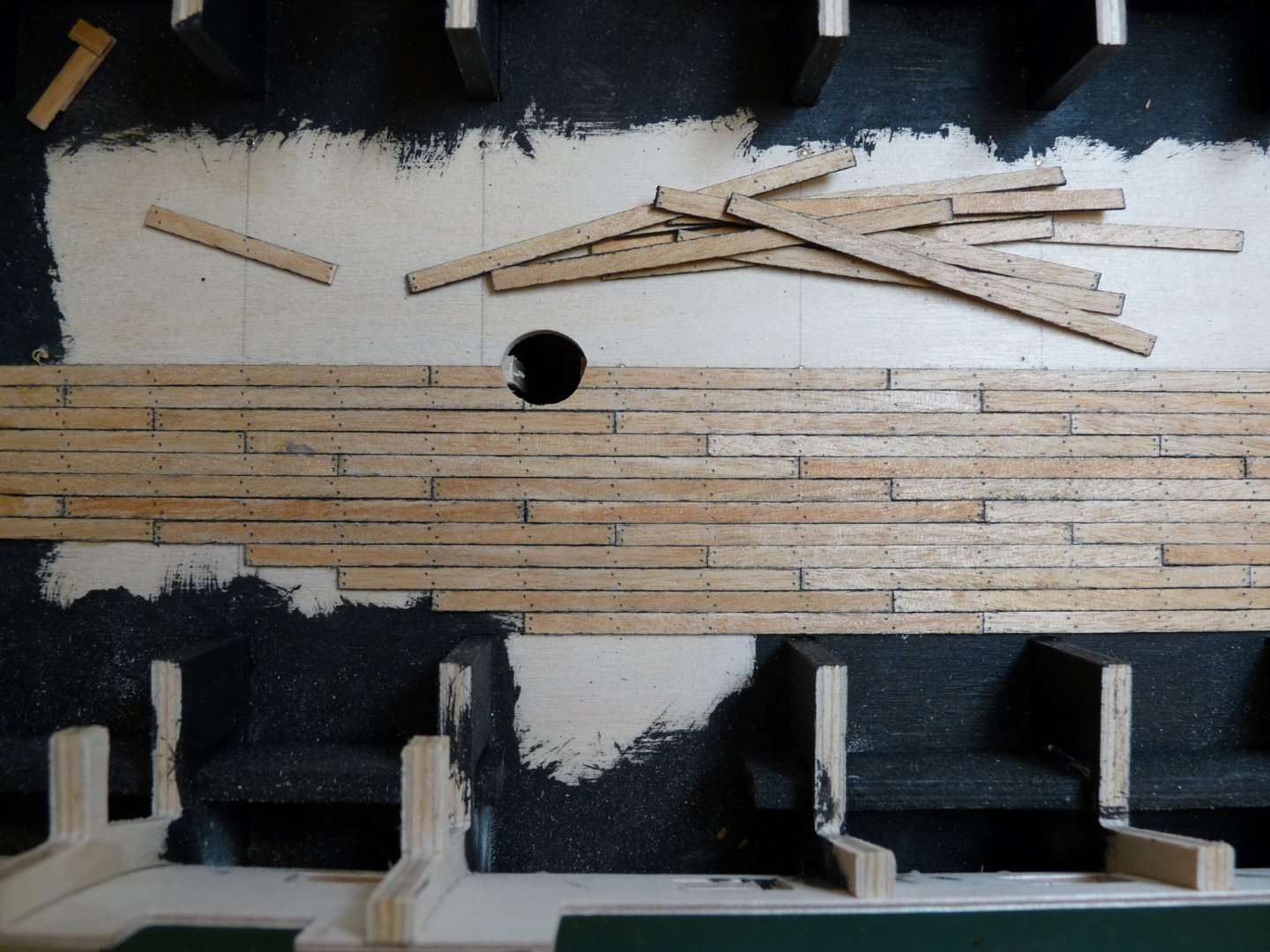
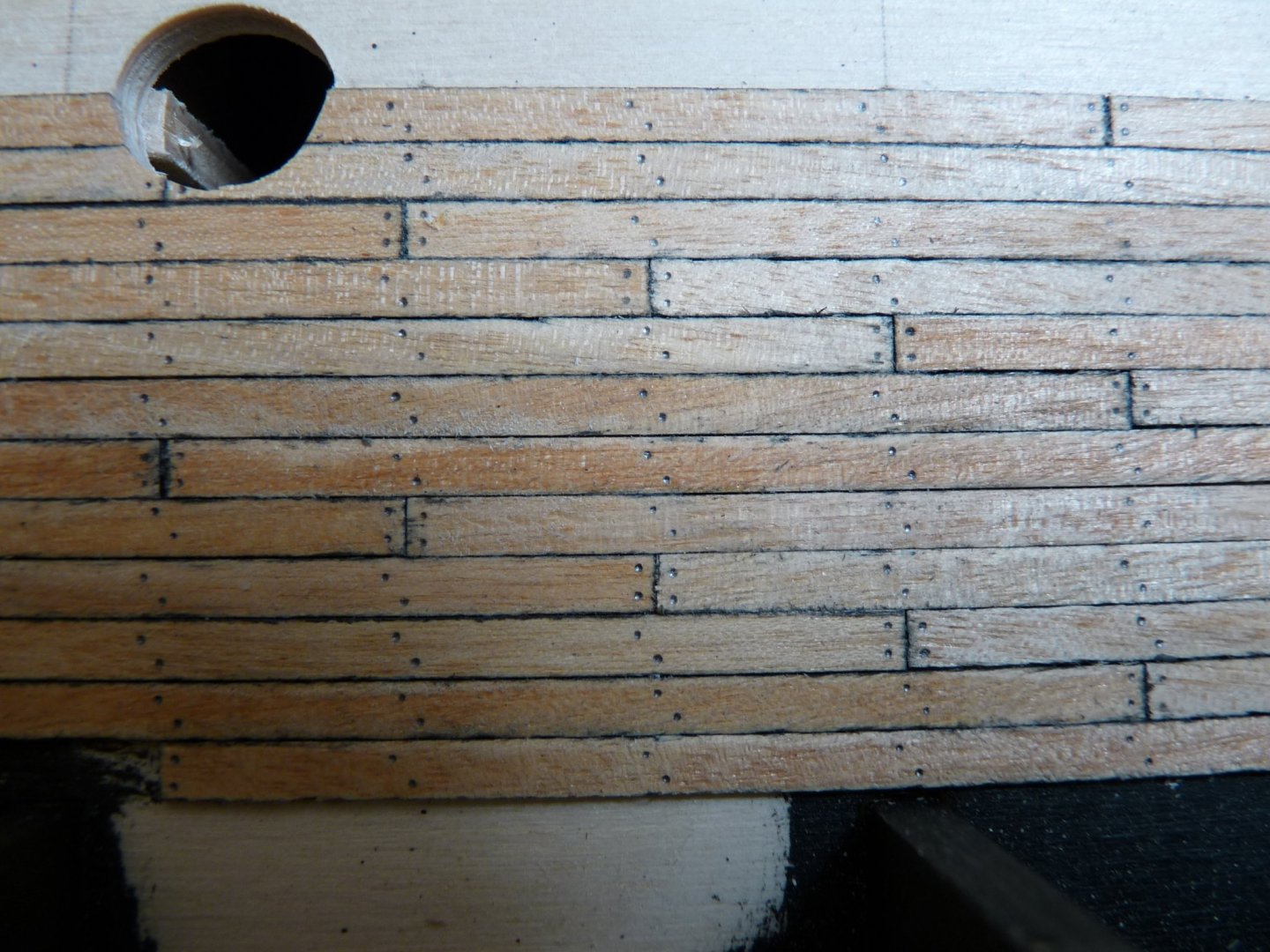
Laying out upper gundeck kingplank, and then planking the UGD. All this will be hidden after the quarterdeck goes on.

-
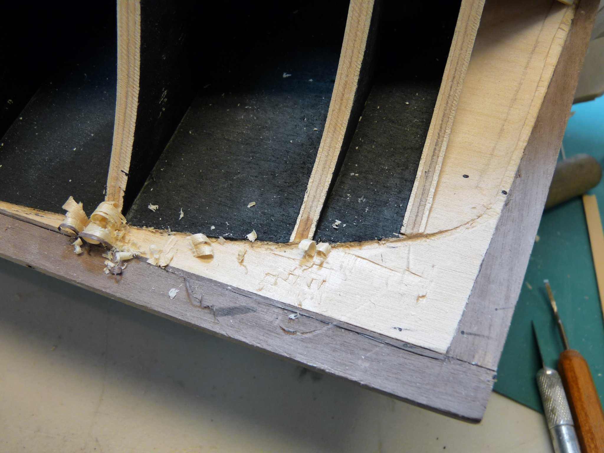
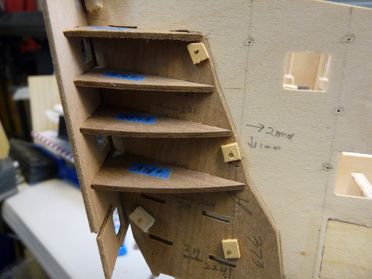
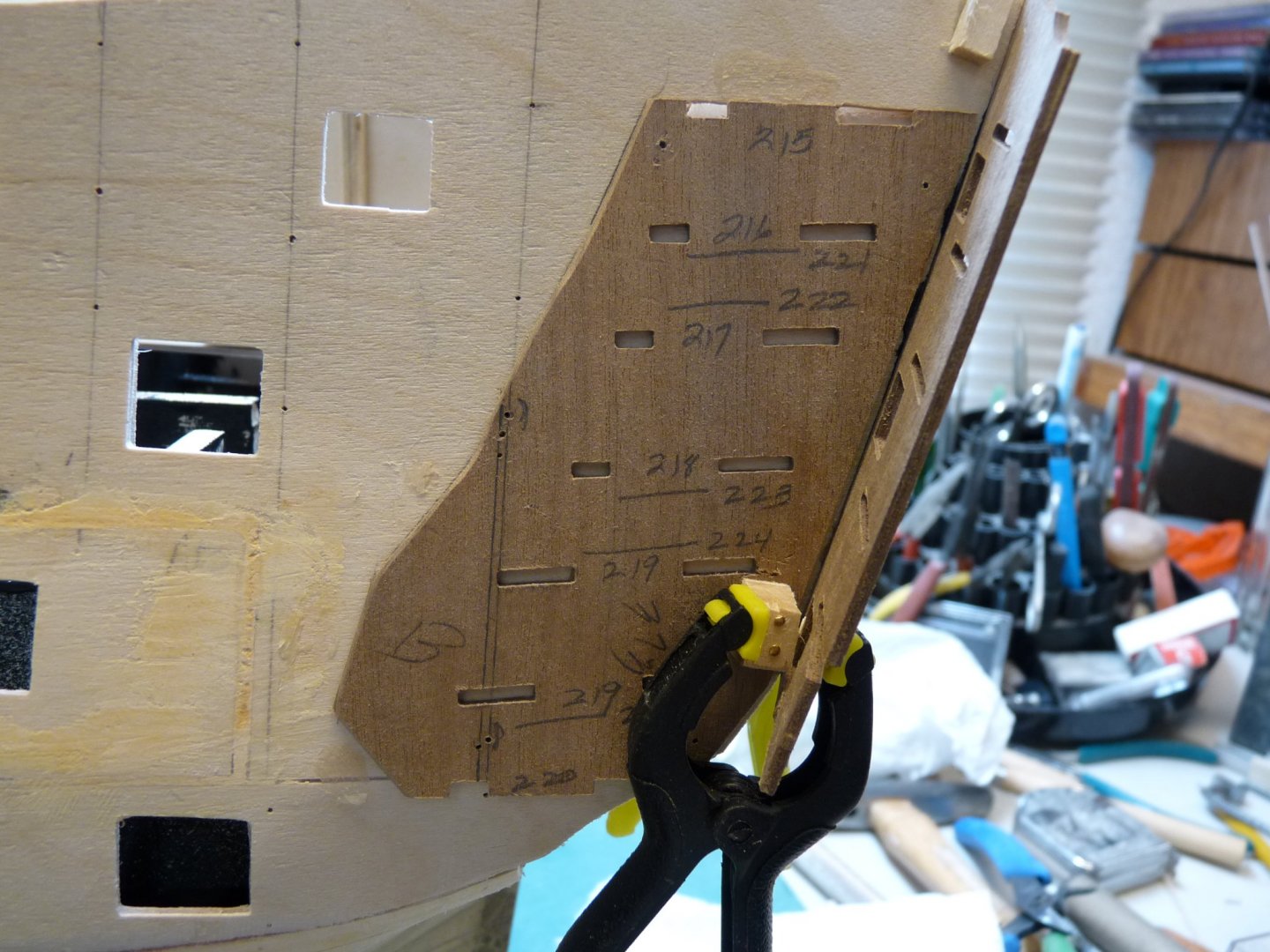
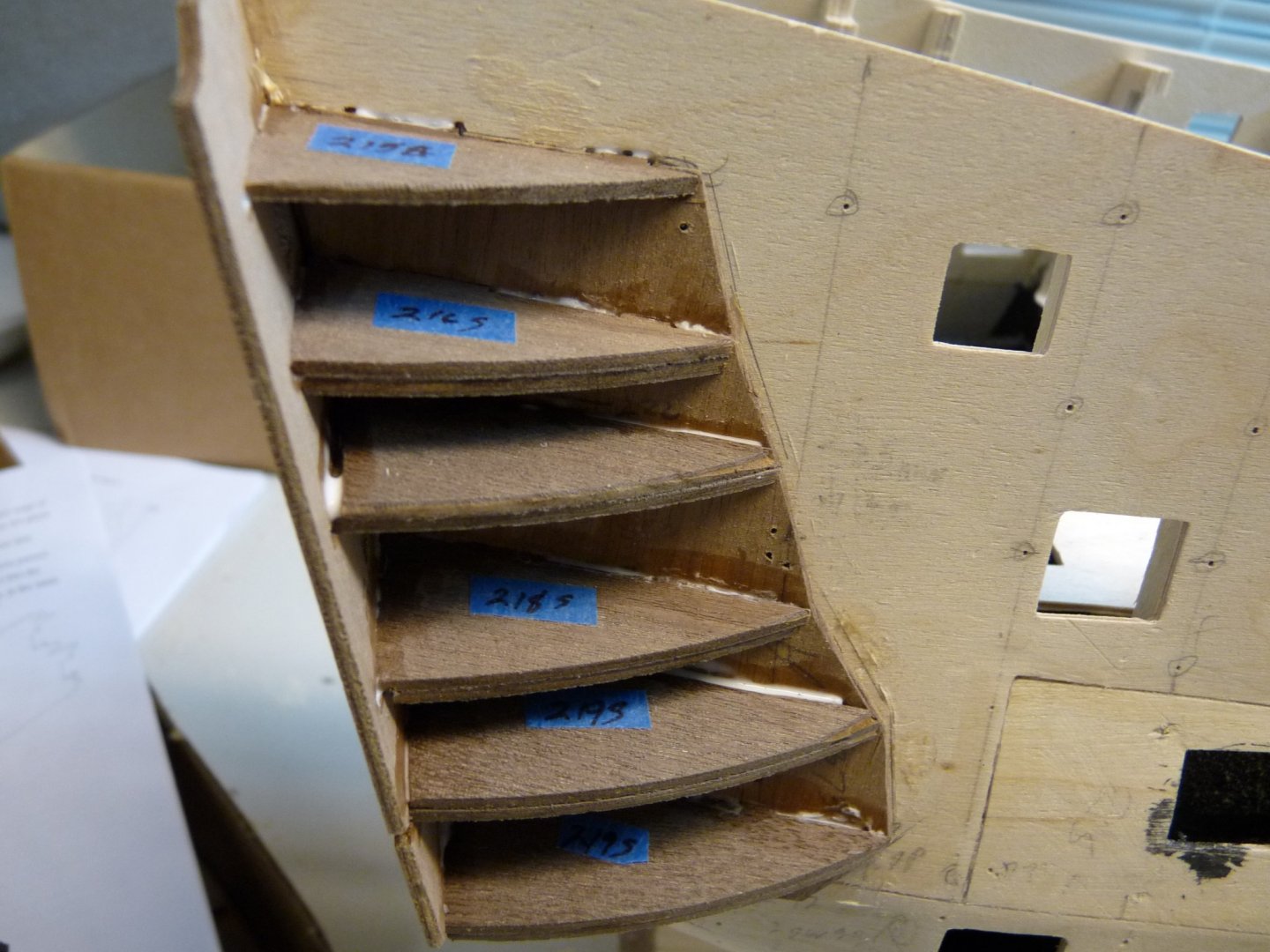
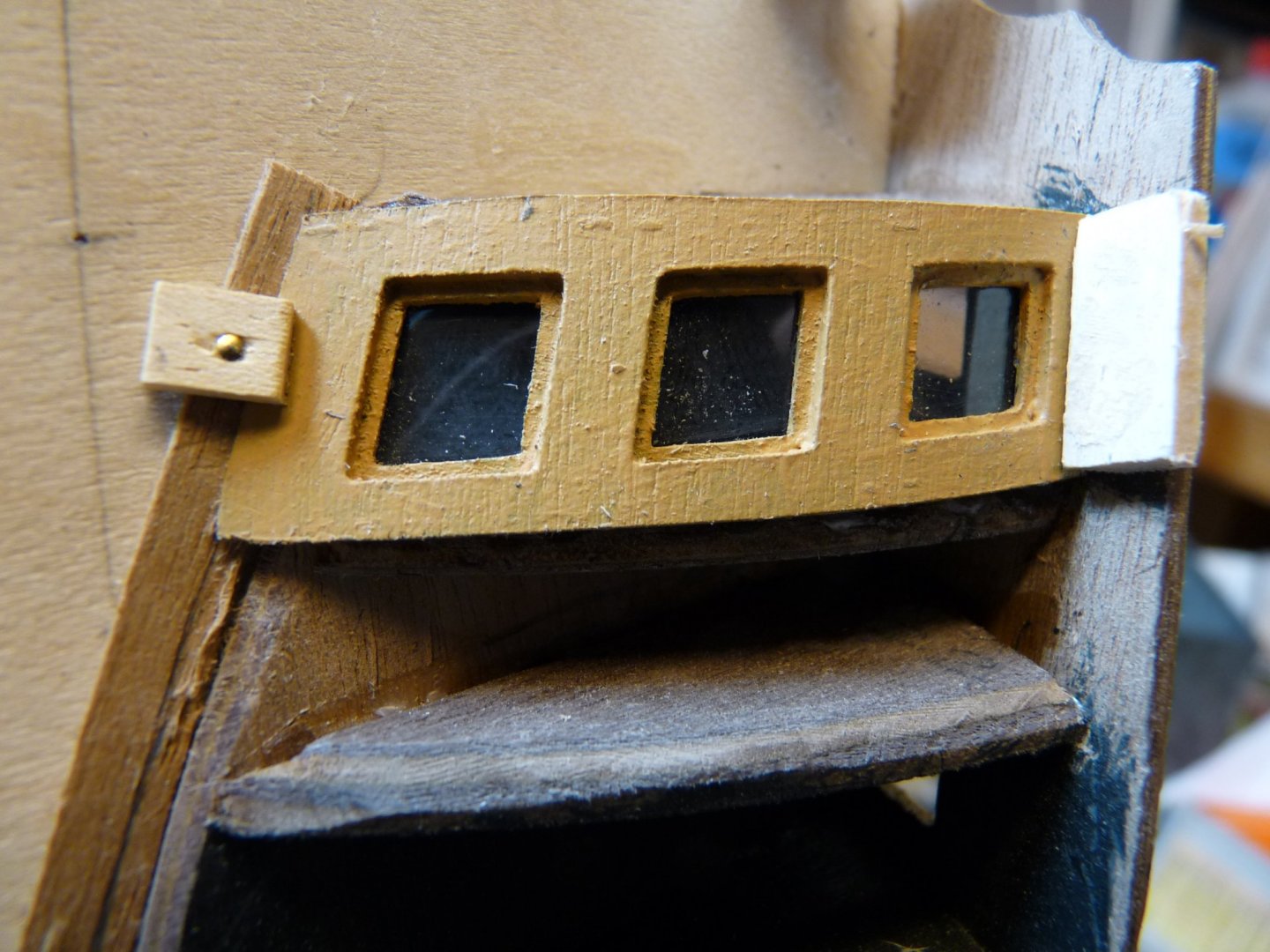
Working on stern fascia and quarter galleries, Feb 2011.


-
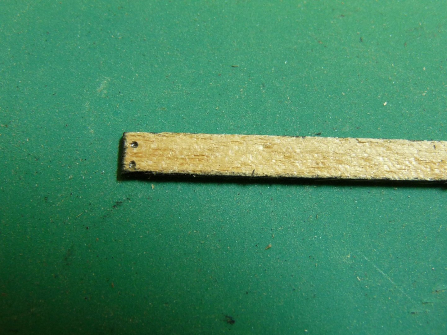
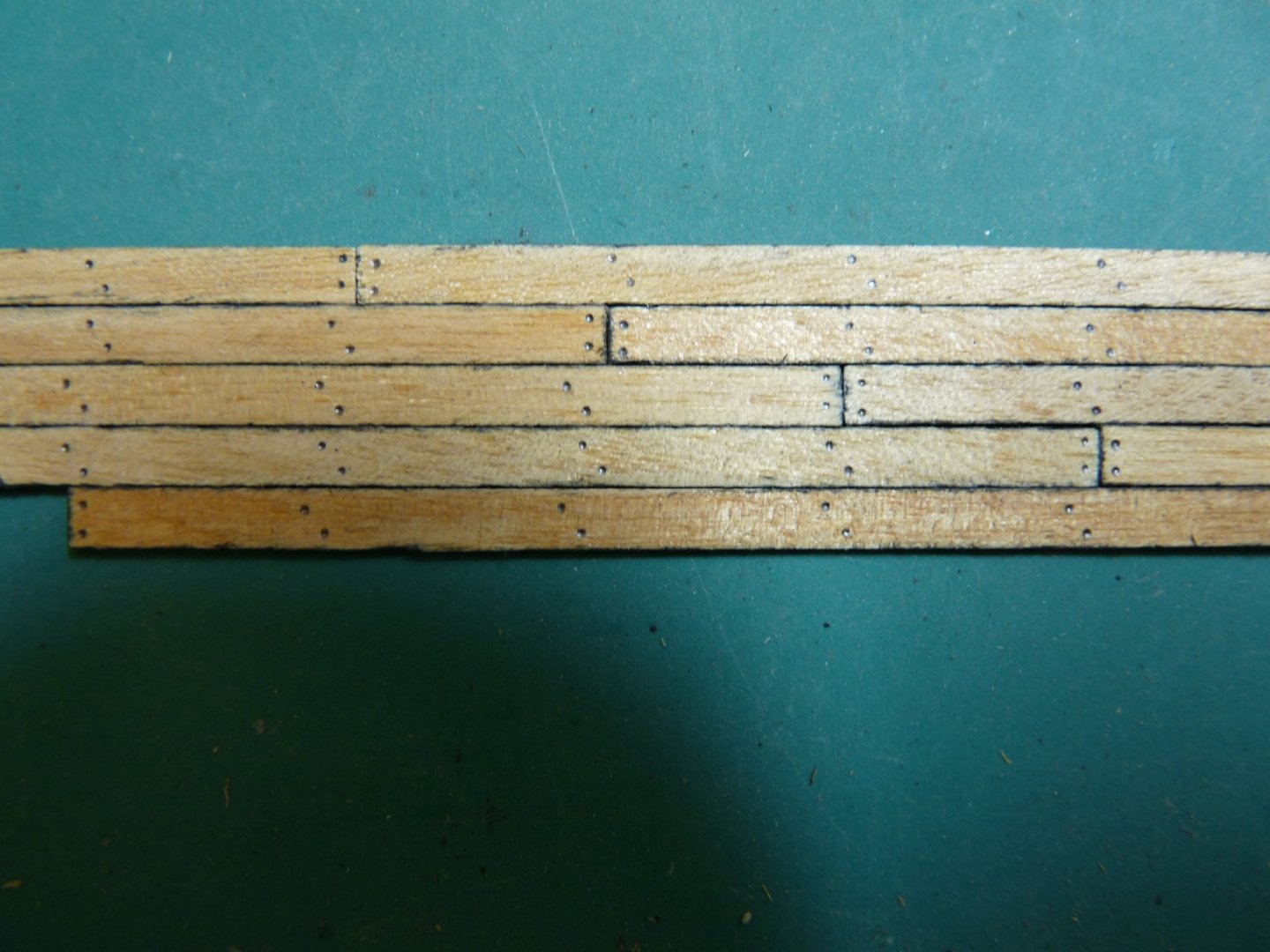
Doing some deck planking. Cut boards to length, sandwich about 20 of them between stiffeners and spray paint board edges & ends. LIght sanding afterwards cleans up any overspray and tones down the darkness. Jig to mark trunnels on boards; one for end pattern and another for those in the middle of the planks. Use a sharp pencil to make marks. then layout a 4 butt pattern.


-
Thanks for looking, Kev. I've seen some of your work here on MSW and it's outstanding!. Your Victory is beautiful. My Vic looks a little worse for wear - unbelayed lines, loose gunport lids etc., but that is the reality of taking pix during the build! She almost looks post-Trafalgar! Will fix the gunport lids later, no use in knocking them off again after they're fixed. Maybe I'll post a series of photos showing how I made the sails - don't know exactly how or where to post. Guess I'll learn my way around the forum eventually.
-
Here are a few more pics from early on in the build. These are from 2011.
-
Hi Paul, Beautiful build! My guess for the lack of a rubbing paunch is that the mizzen is gaff-rigged. The crojack was not hoisted very often, and also the driver lashing on the lower mizzen mast may have been interfered with by a rubbing paunch. Best regards, Ted
-
Hi. I just found the MSW rigging spreadsheet, and was delighted as I spent a lot of time developing a similar one for my 1;72 Victory. I just wanted to point out that there seem to be some errors in the calculations, so beware - check the math. I entered the data for Victory, and noticed that the ratline diameters given in the table are consistently wrong - they are often 30% larger in diameter that that mast's stay! Same goes for snaking. I tried it for several input parameters (scale, date of launch and rate), and it is consistently wrong. It seems to be a problem with original ropes of 1.5" circumference, but there may be other computational errors as well. The table is really helpful, but if the given scale rope diameter seems too large, check the math manually!
-
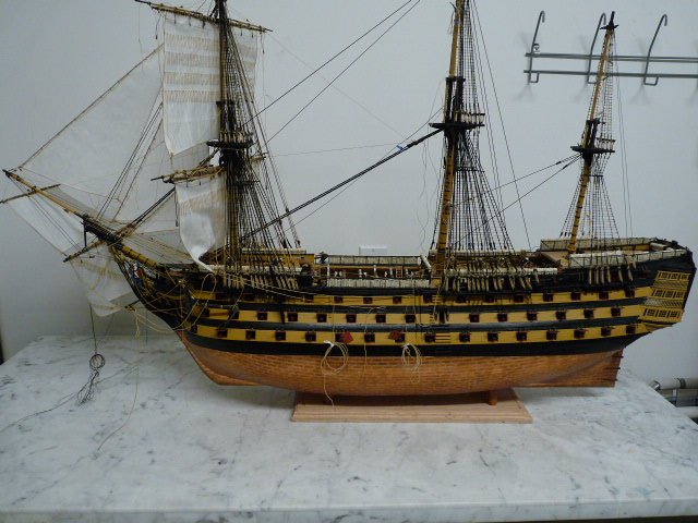
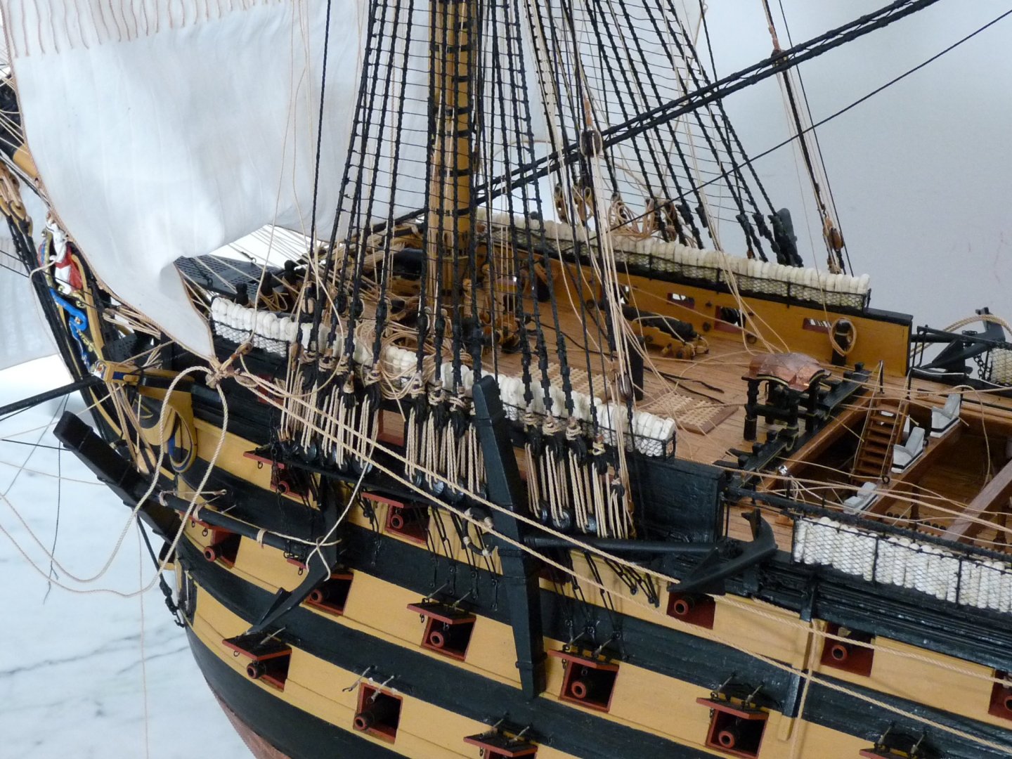
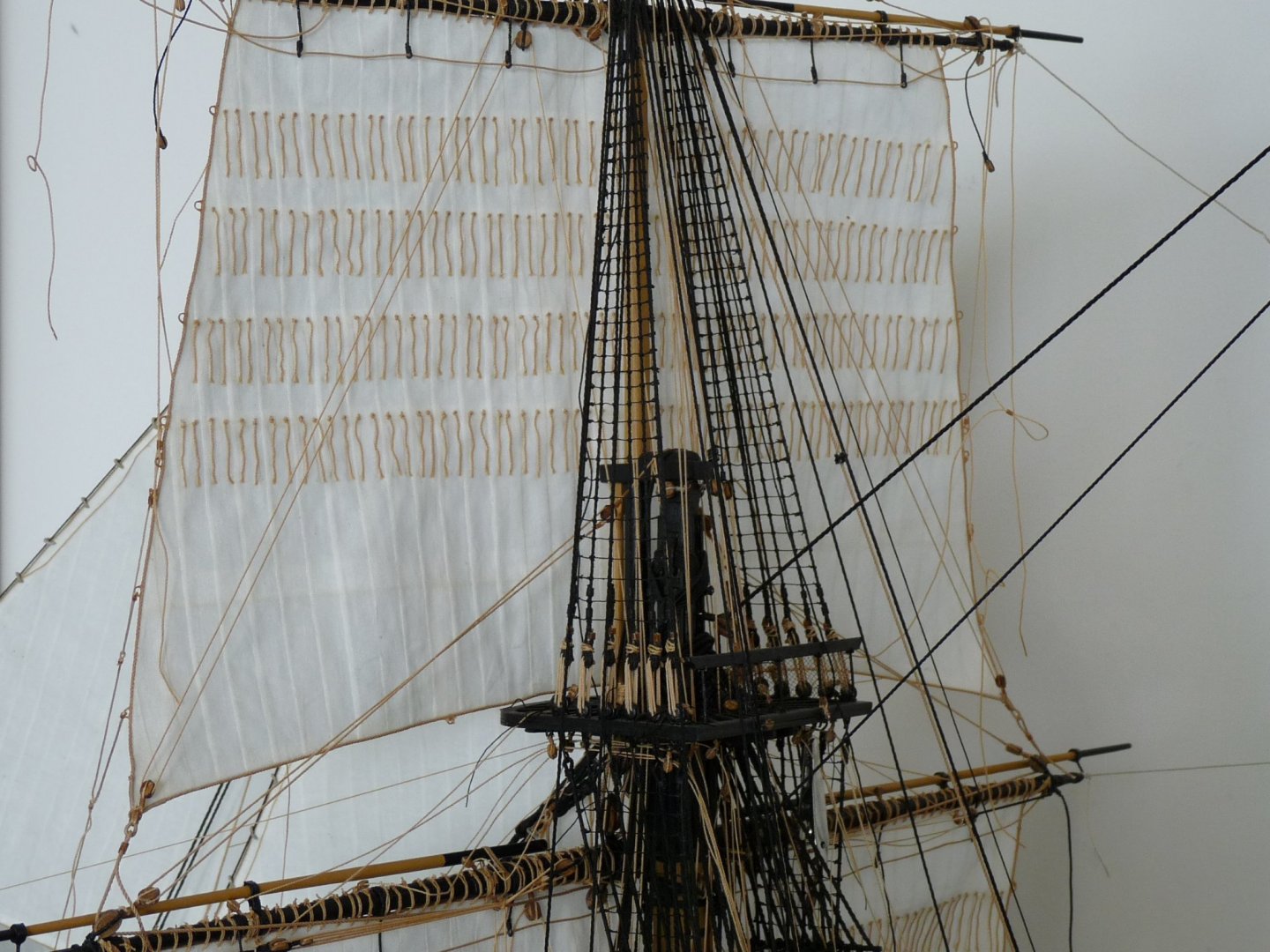
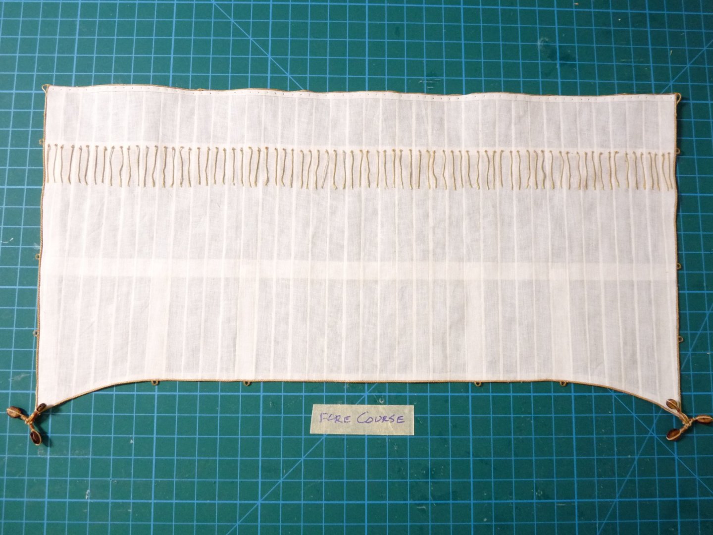
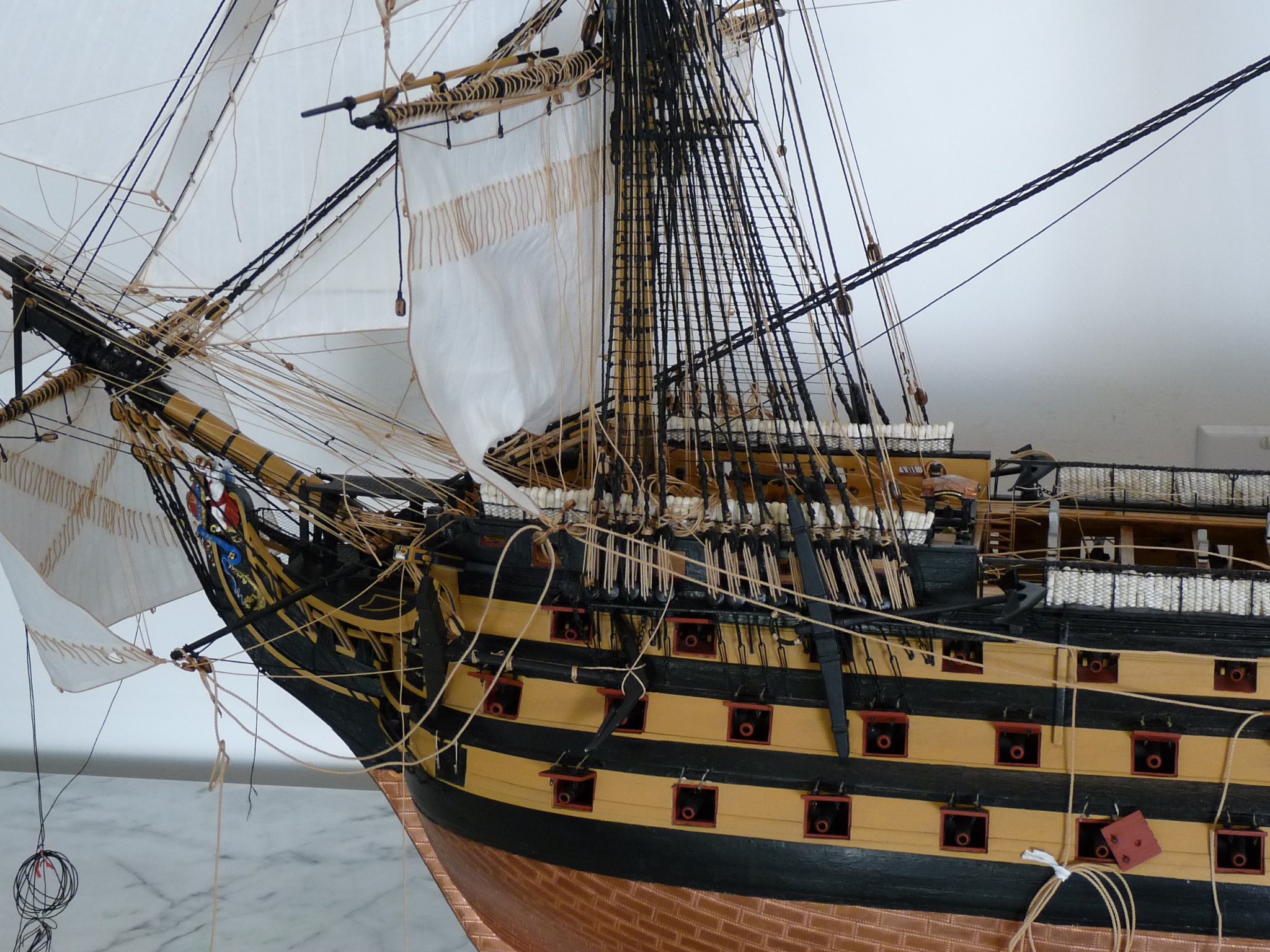
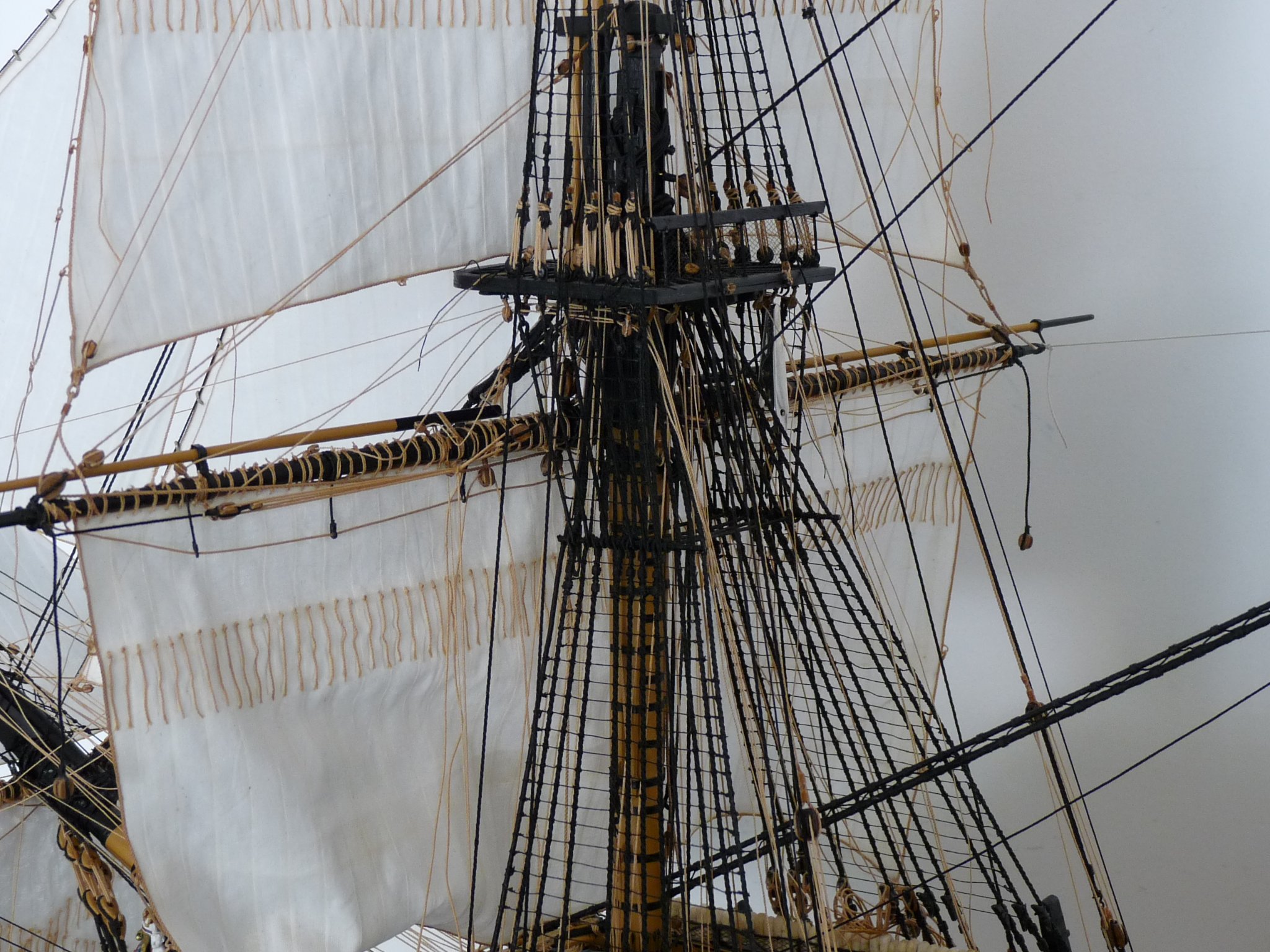
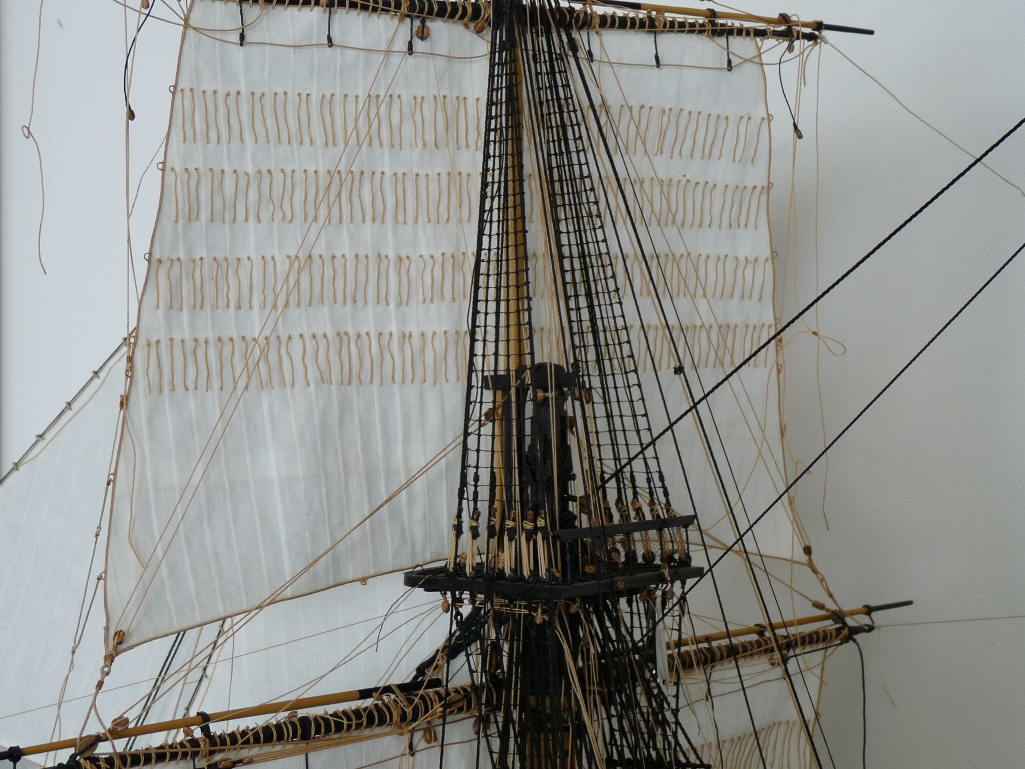
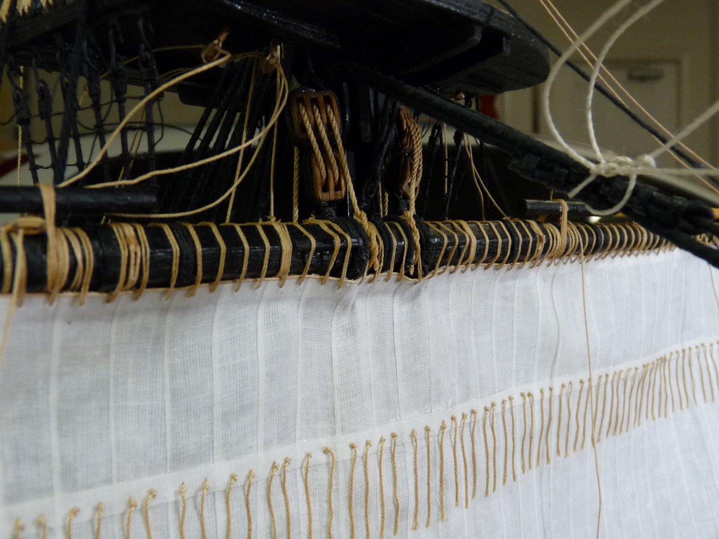
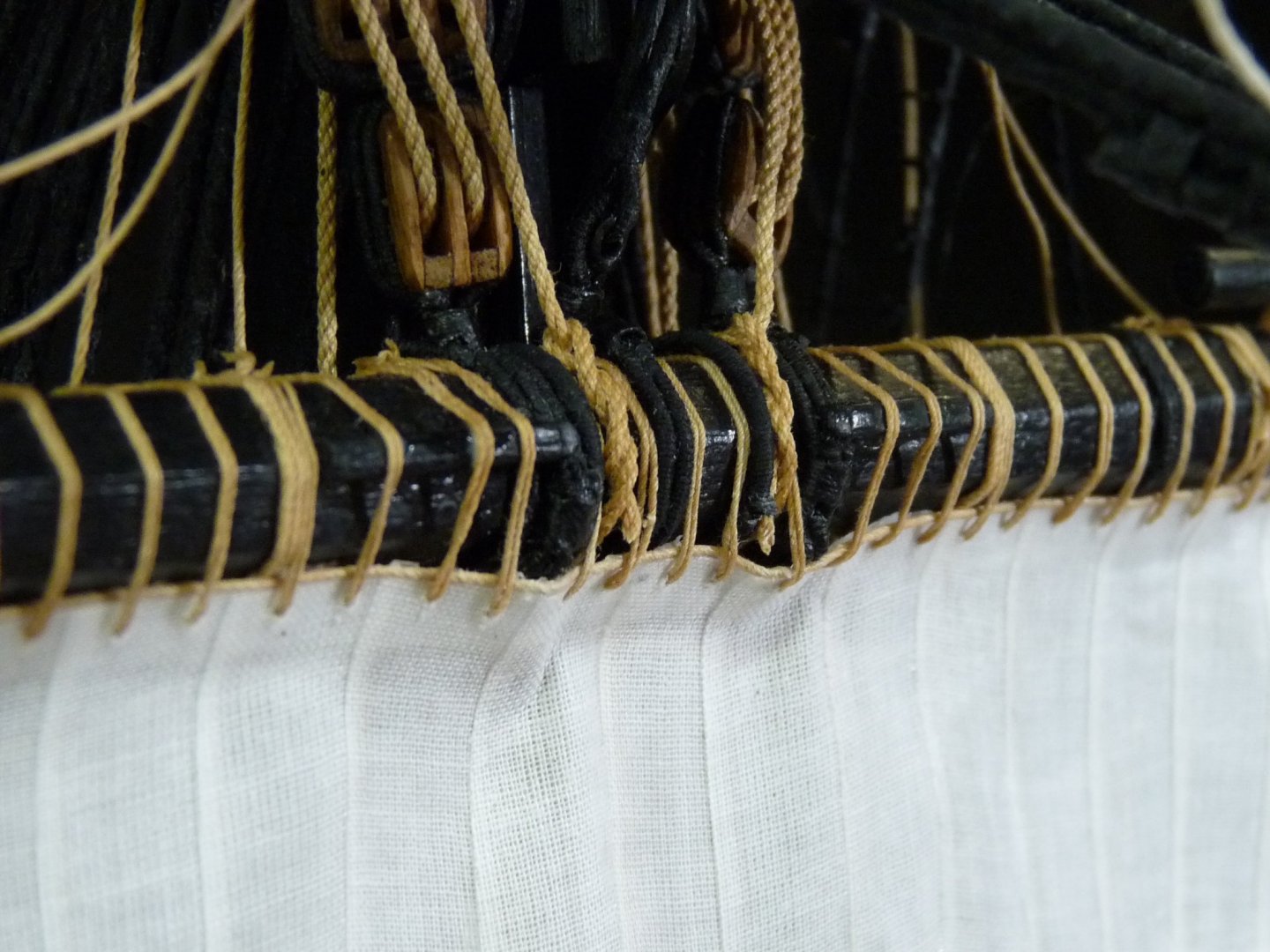
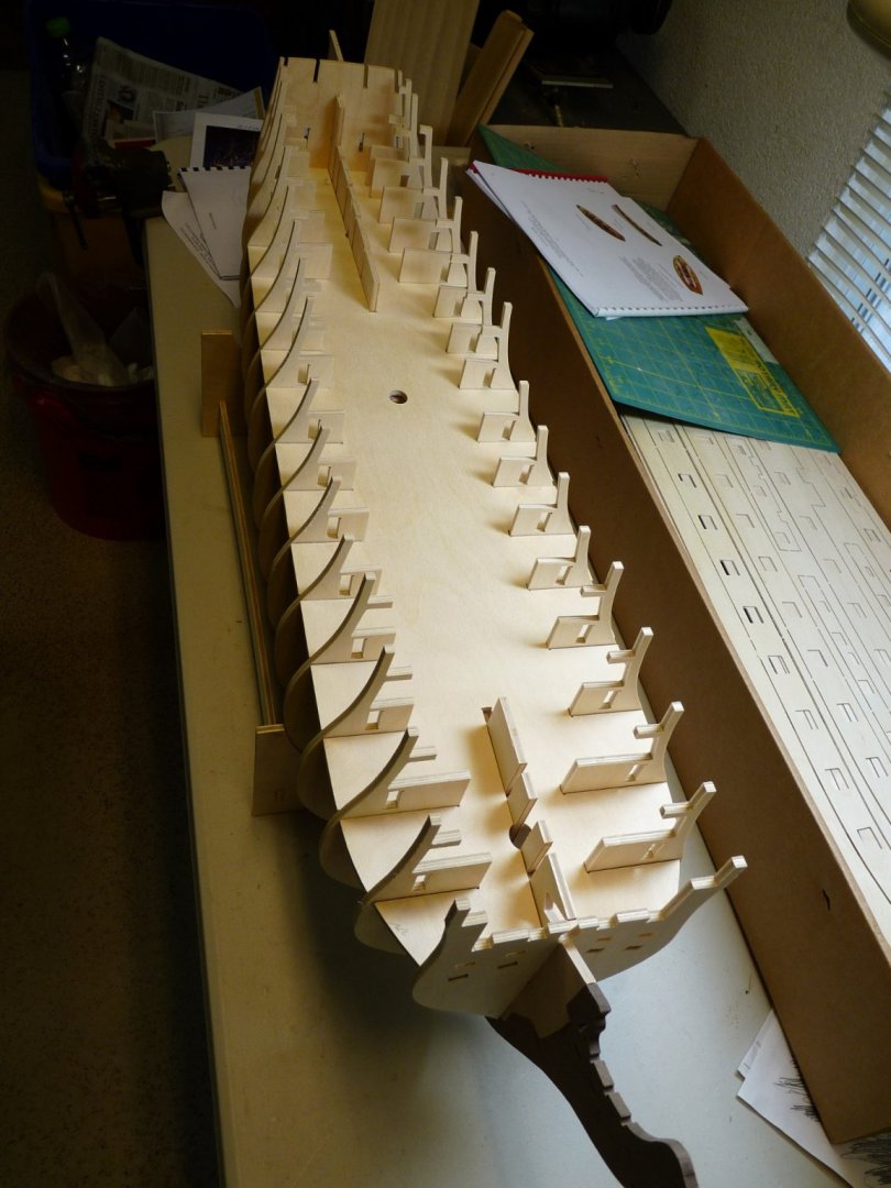
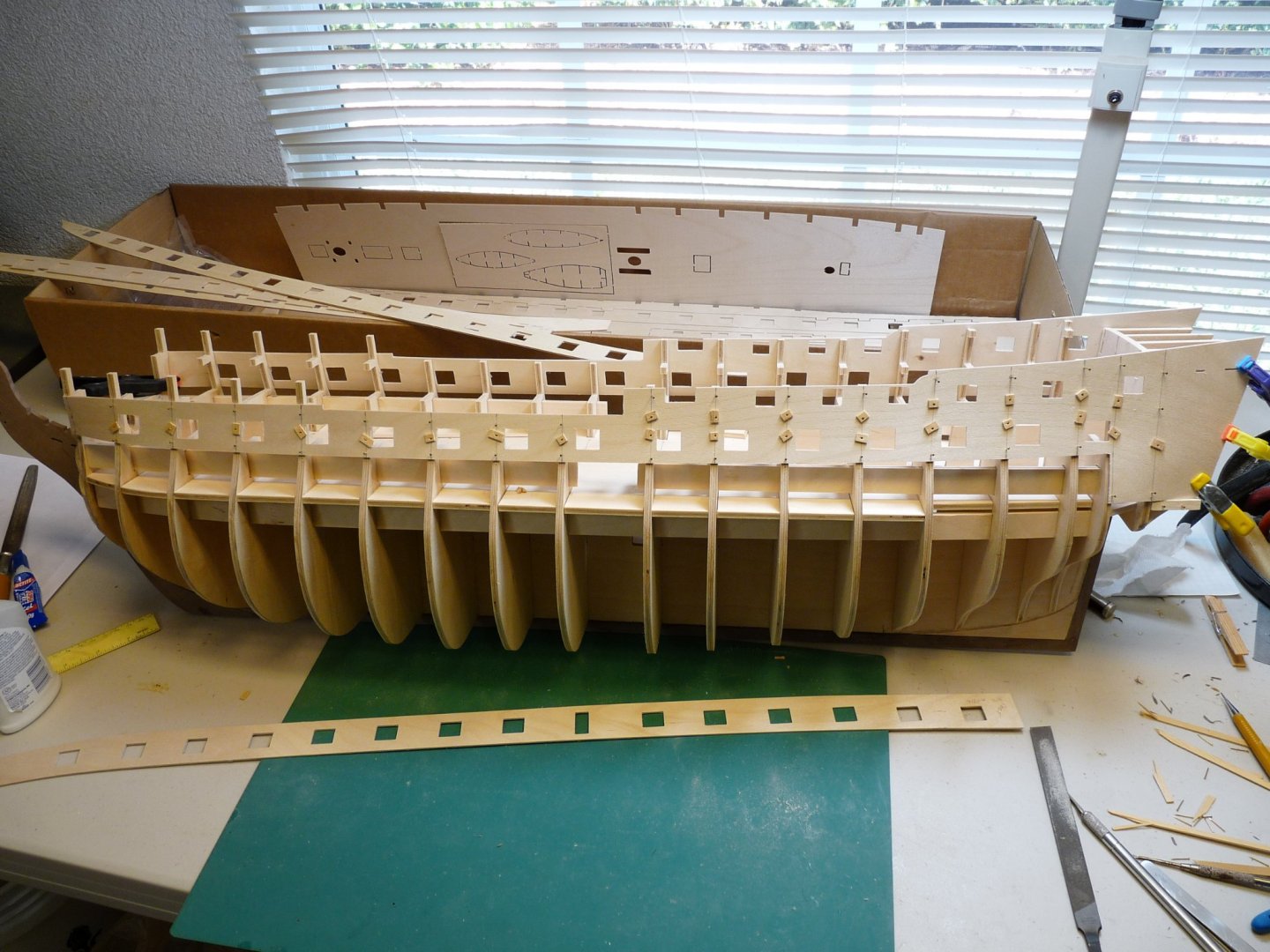
Hello all. I've been a member of this forum for many years, but have never posted a build log before. I'm a little late to the party here, as I started this build over 11 years ago. I actually took a few years off in the middle, and am now in the final laps of this journey. I had made two previous models, and this time I wanted one that had a lot of detail, and was authentic, so I decided on Caldercraft's Victory. It was, in retrospect, a good choice, because there are tons of sites and photos of the actual ship available on the net for research. At this point I have put in a little over 4300 hours in the build, not to mention the hundreds of hours spent in research, making spreadsheets etc. I'm posting here a few pix of the current state of the build, perhaps later I can add some earlier shots as well. I apologize for the quality of some of the photos, as the light in the workshop is pretty poor, and I don't spend a lot of time trying to make them look pretty - they are more for documentation's sake. My build process is a little unorthodox, I guess, at least for the rigging part of it. From prior experience I have learned that fragile pieces sticking out are disasters waiting to happen. Therefore my masting/rigging process went something like this. (Note that all masts and spars have been previously built and have the blocks, etc attached). Install all three lower masts with tops in place and the bowsprit, then add lower shrouds and bobstays. Rattle down all lower shrouds, then add futtock shrouds. Next step is to add all topmasts and the jibboom, then install the topmast shrouds and rattle them down. So, these pix show that the topgallant masts and the flying jibboom are still uninstalled. At some point in the build I had to decide whether or not I wanted to add sails. I was generally disappointed in other sails that I have seen in that the stitching that is supposed to represent the sail seams was way out of scale and was way too apparent and obvious. I spent a fair amount of time developing a procedure for making what I think are more realistic sails, I am happy with them, so I am going for a full suit of sails for her. I also had to make a decision on how to display the model, and after much thought decided to depict Victory as she made her turn to port in her run to break the Combined Fleet's line. Her courses would have been clued up to avoid catching fire from the weather deck's muzzle blasts, and she would have been sailing in a light wind on a port tack. Getting the sails right to suggest this scenario is my current challenge, and I am wrestling with getting the fore course to look right. Presently 3 of the 4 head sails, along with the spritsail and sprit topsail, as well as the fore topsail are in place. After I get the fore course to look right, I will go on to the main course and topsail, followed by the main staysails. Then on to the mizzen - driver and topsail, then the mizzen staysails. The final step will be shipping the topgallant masts and flying jibboom and their sails. Enough for now; I'll add some more pix later on. Thanks for looking