tedrobinson2000
-
Posts
153 -
Joined
-
Last visited
Content Type
Profiles
Forums
Gallery
Events
Everything posted by tedrobinson2000
-
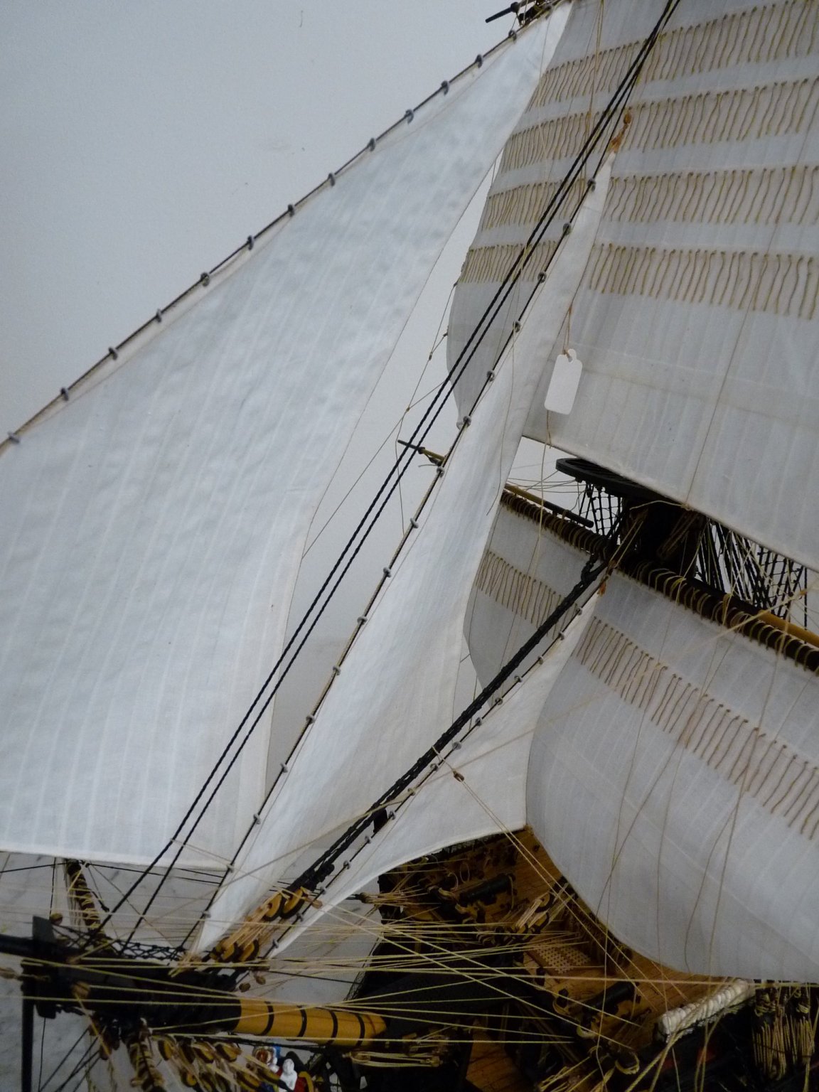
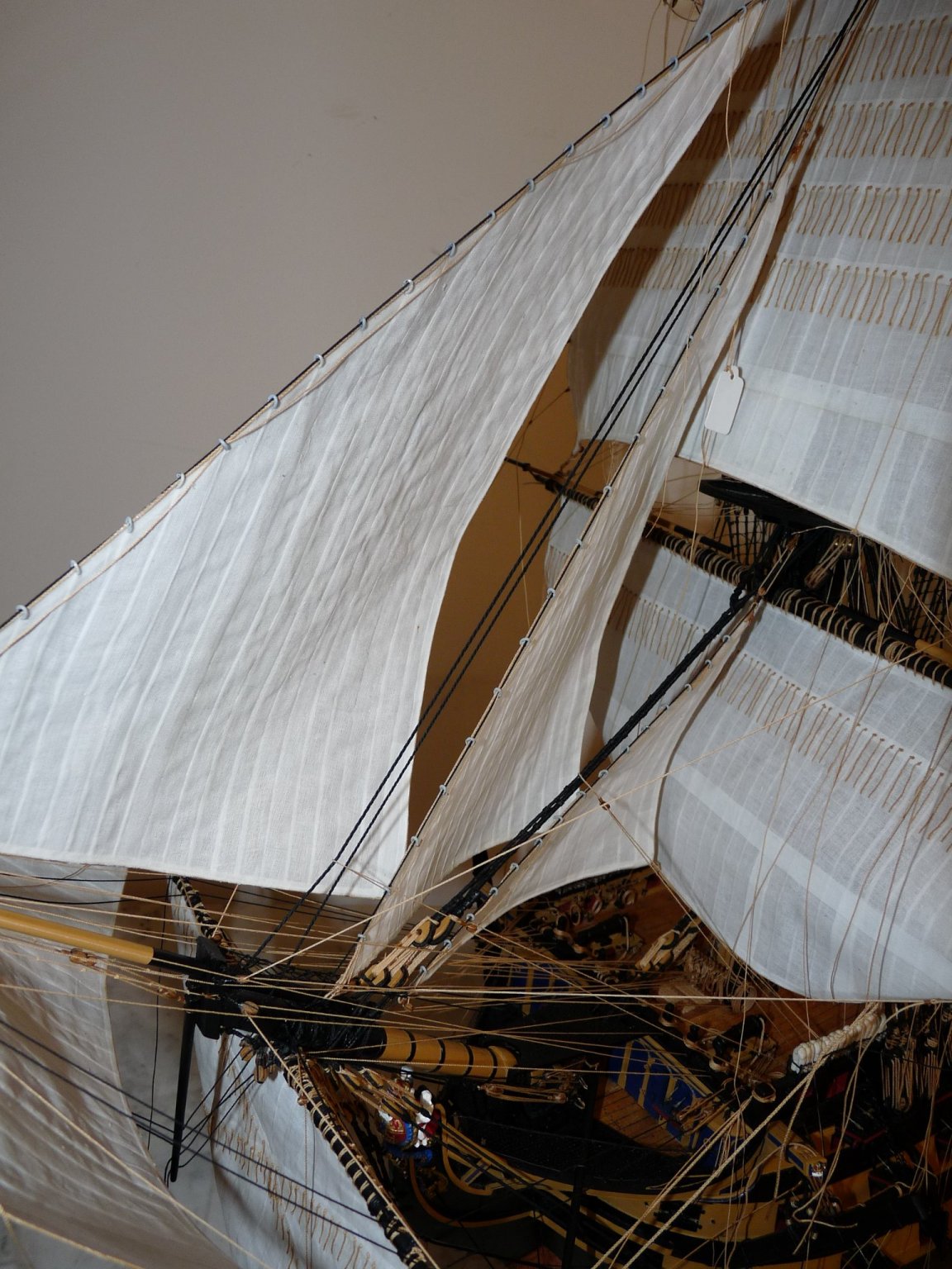
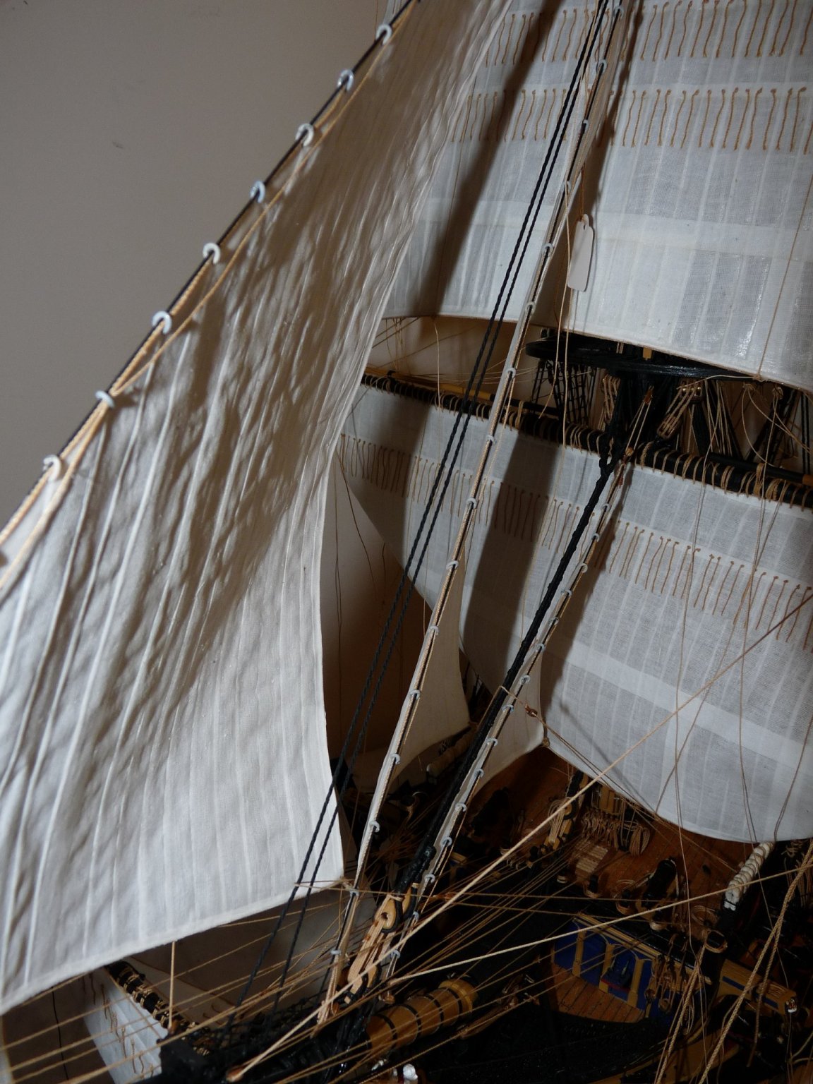
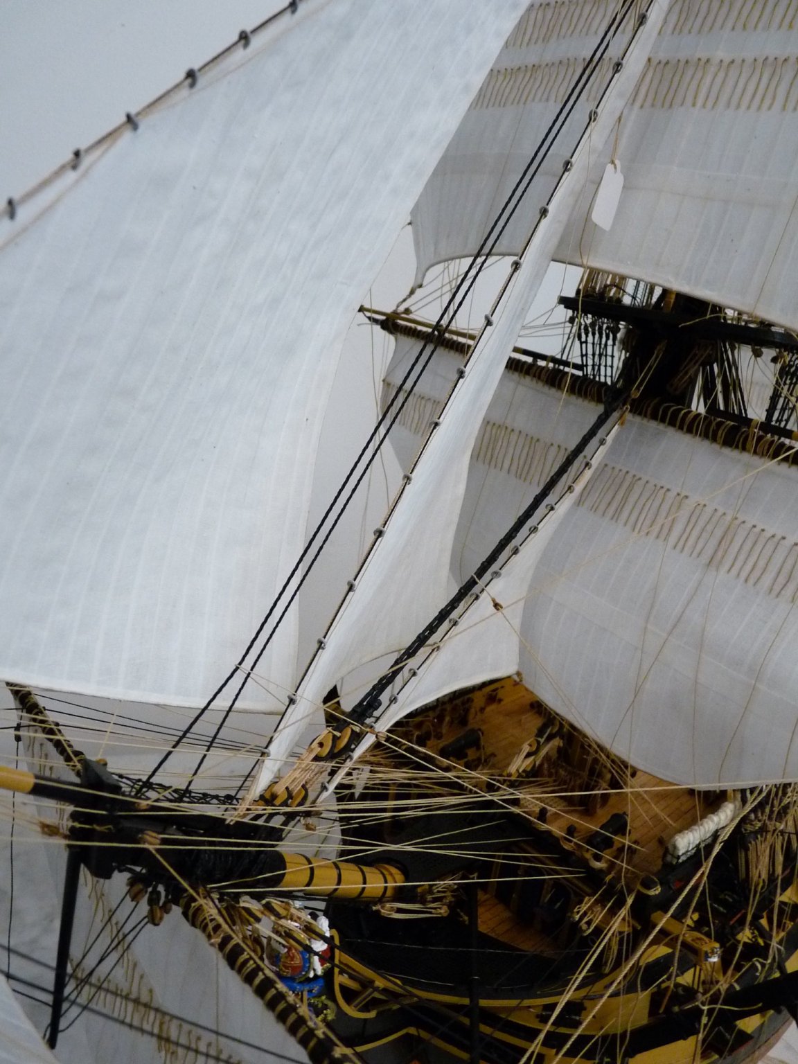
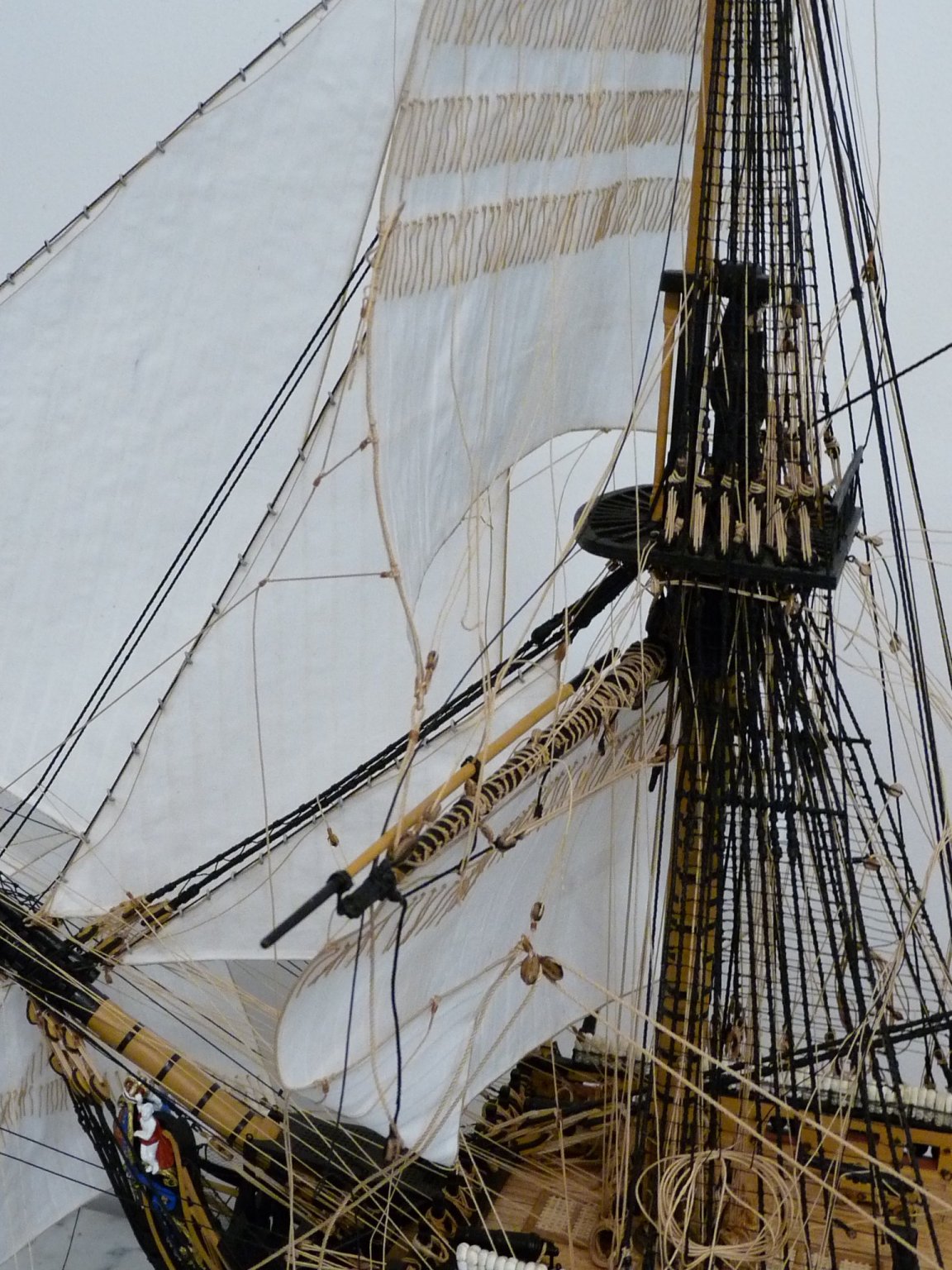
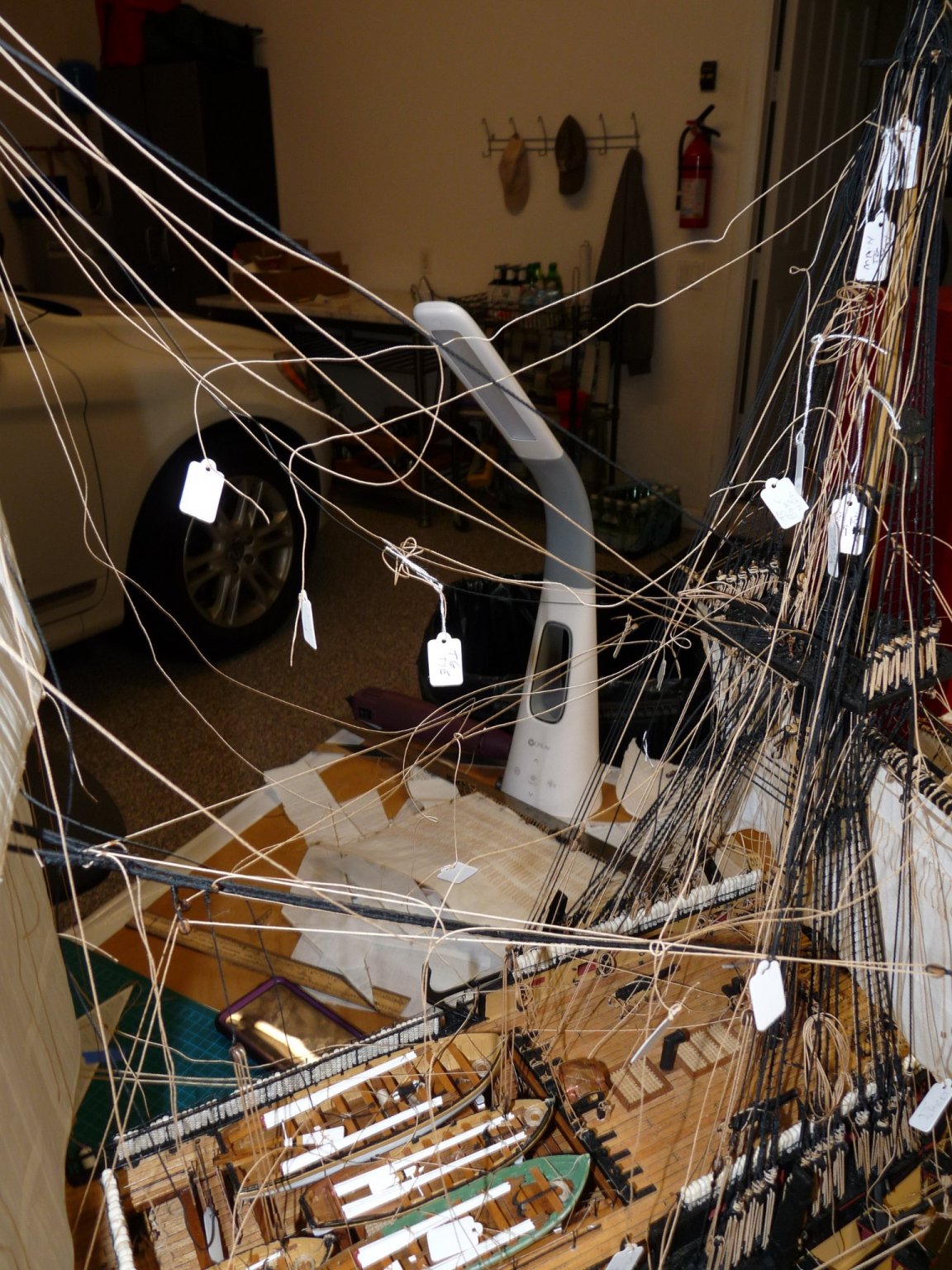
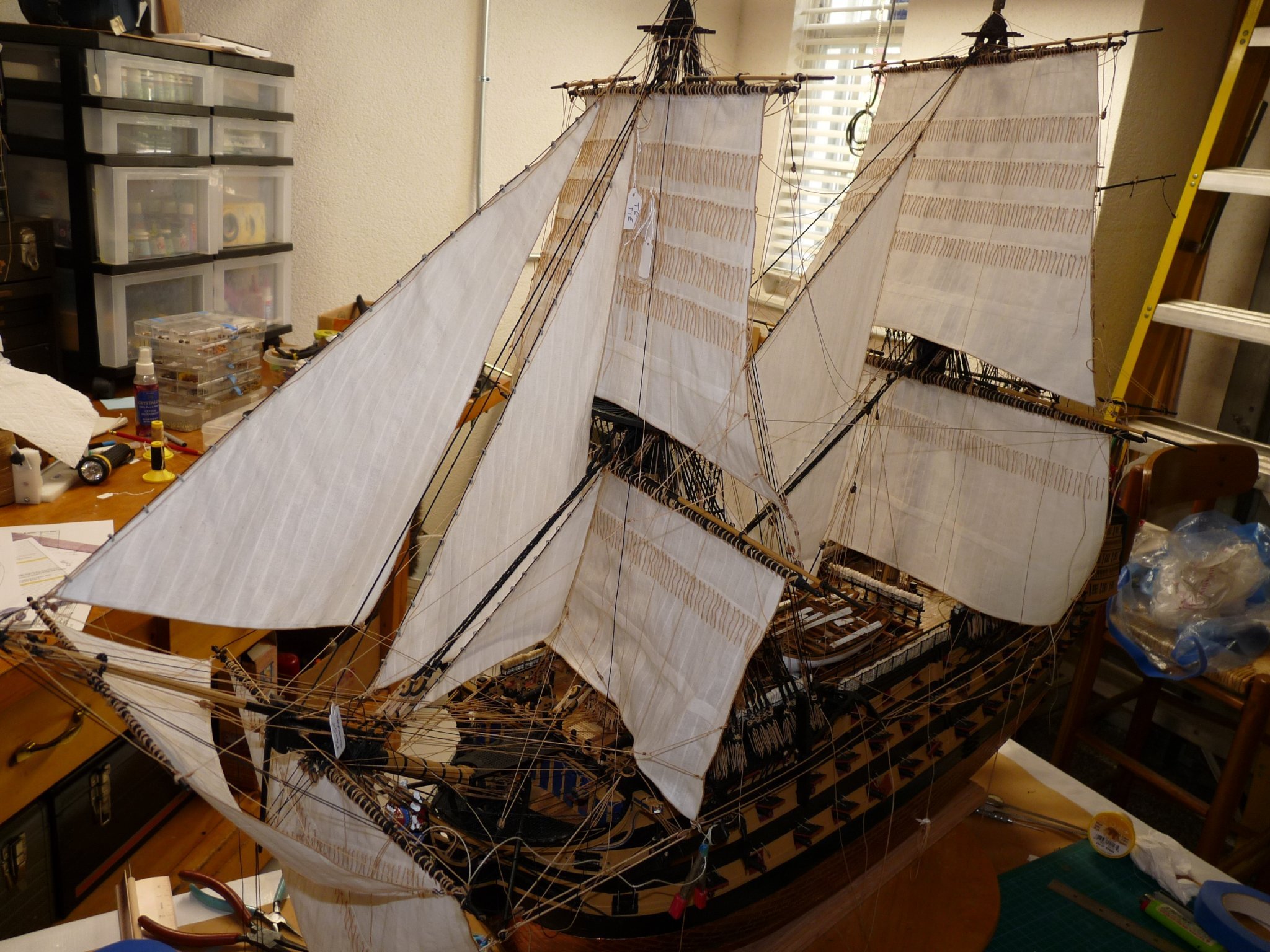
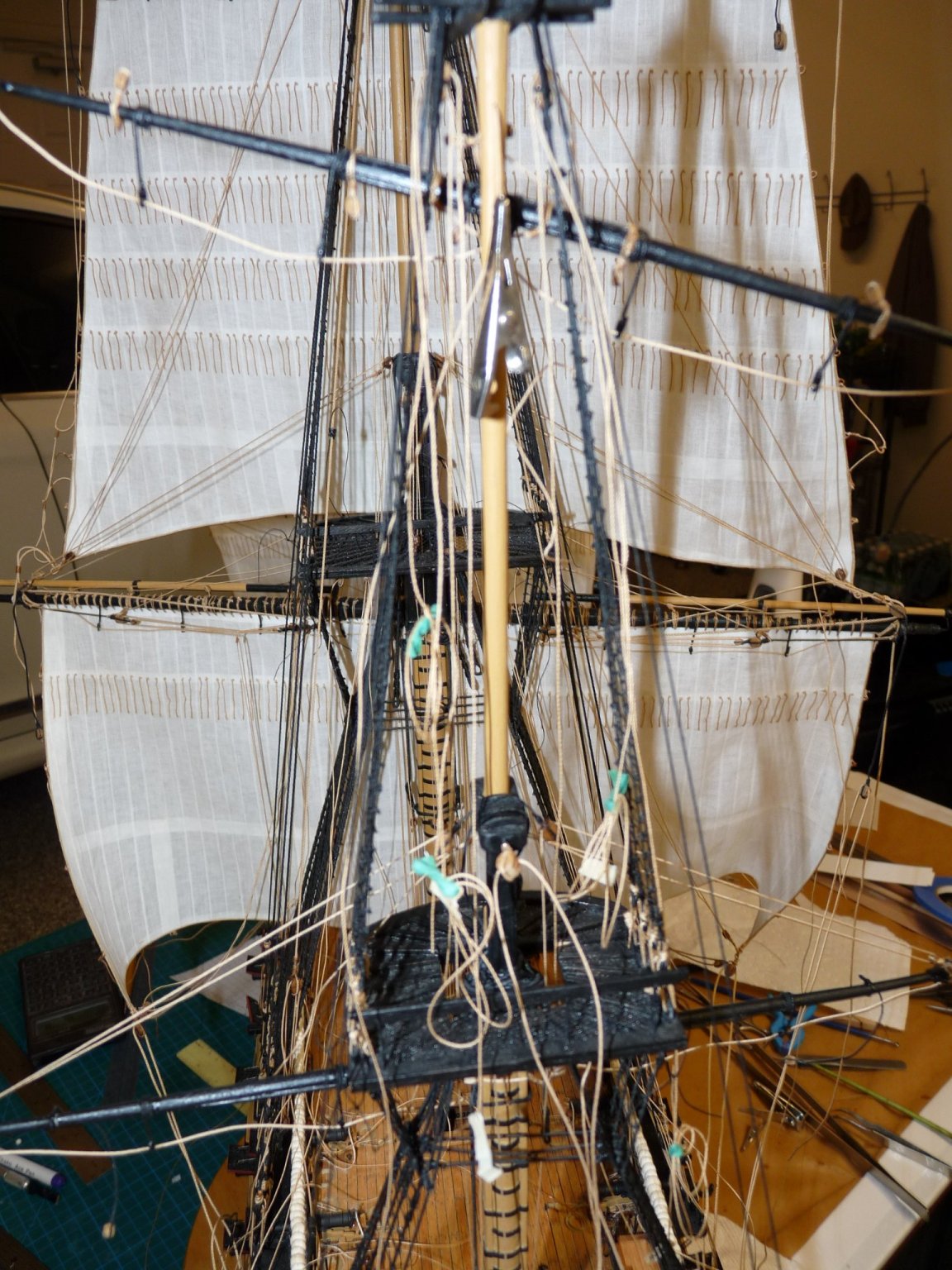
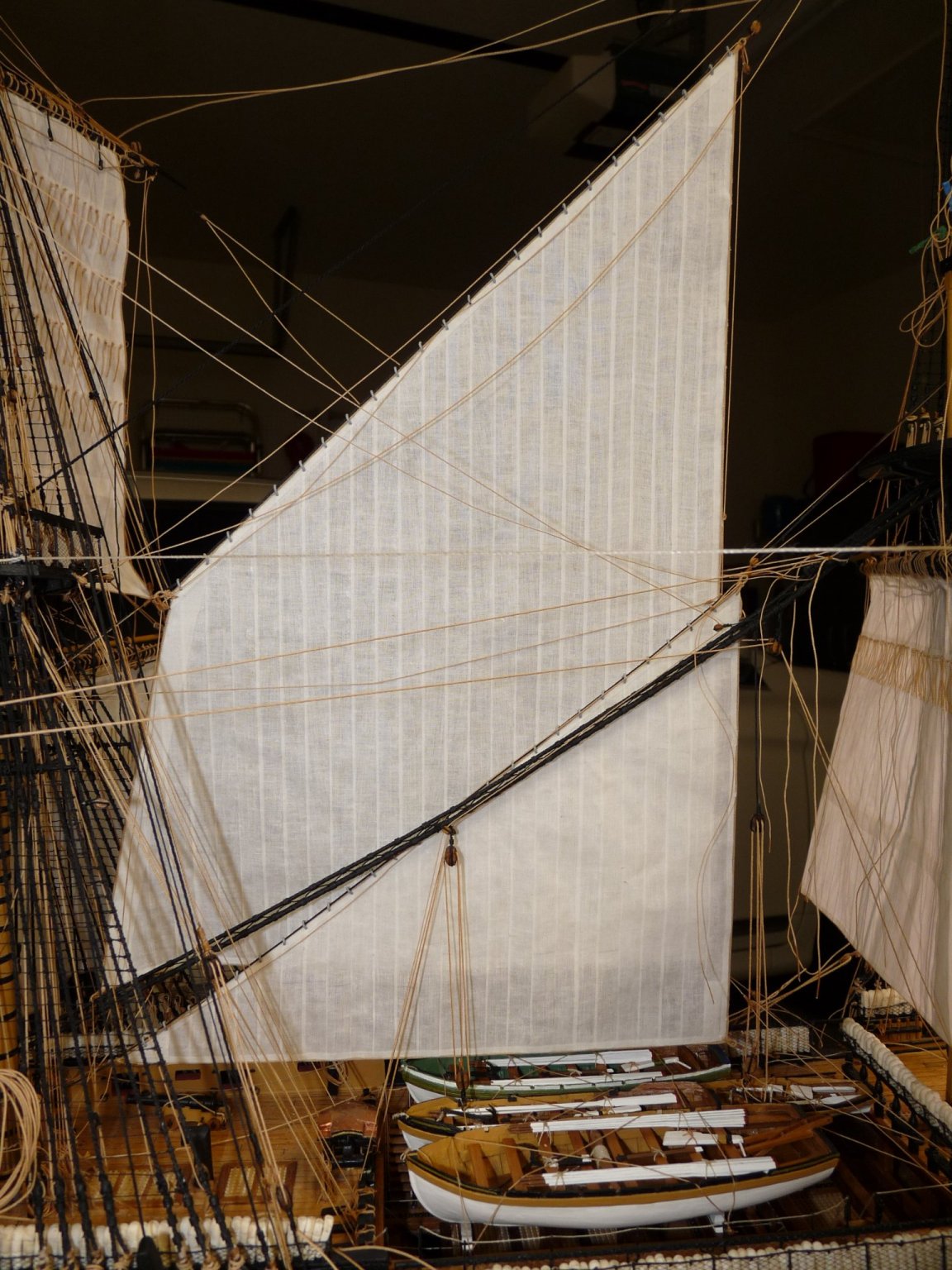
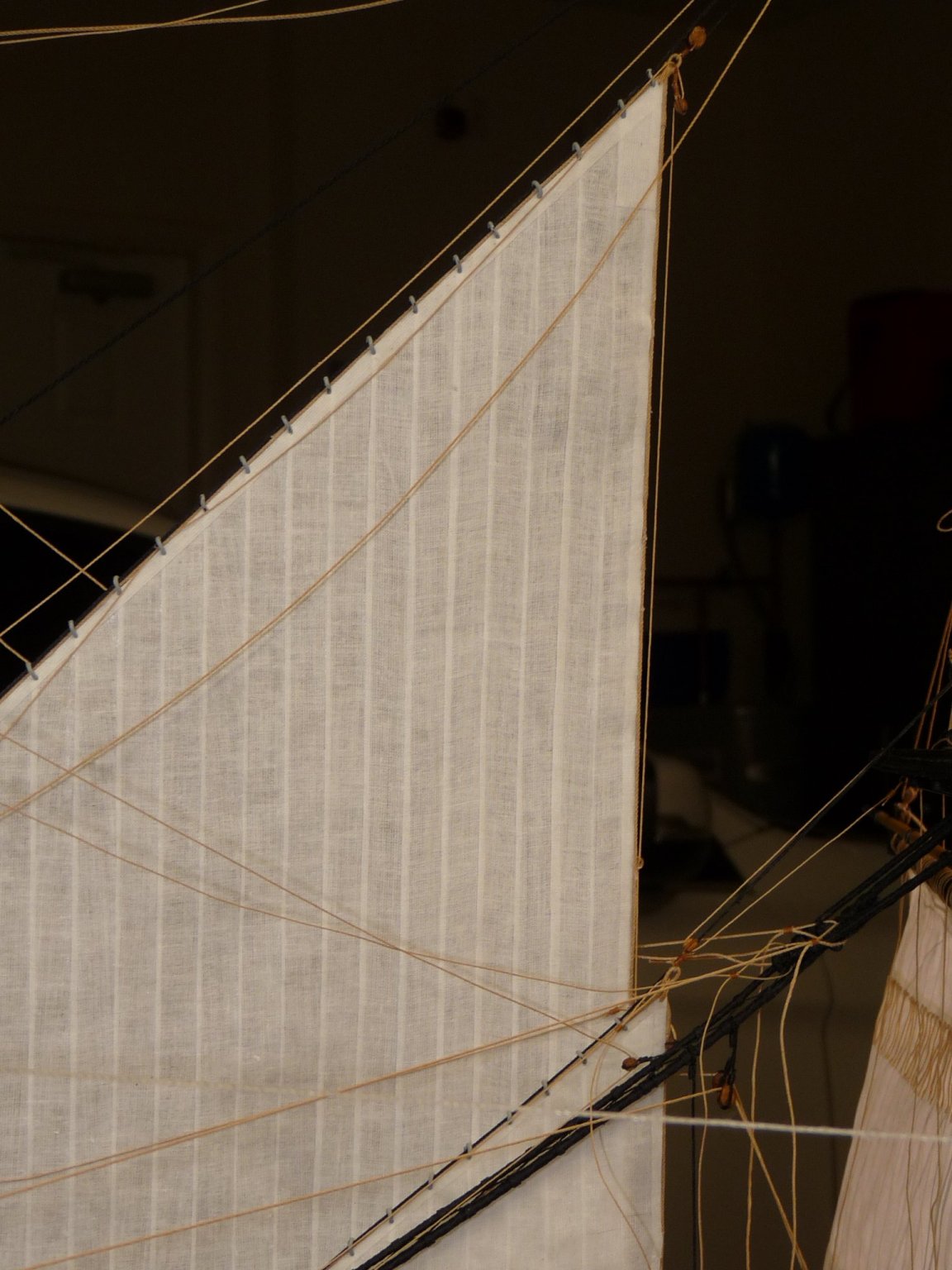
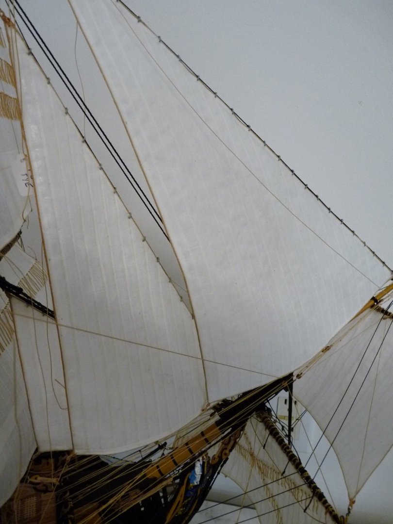
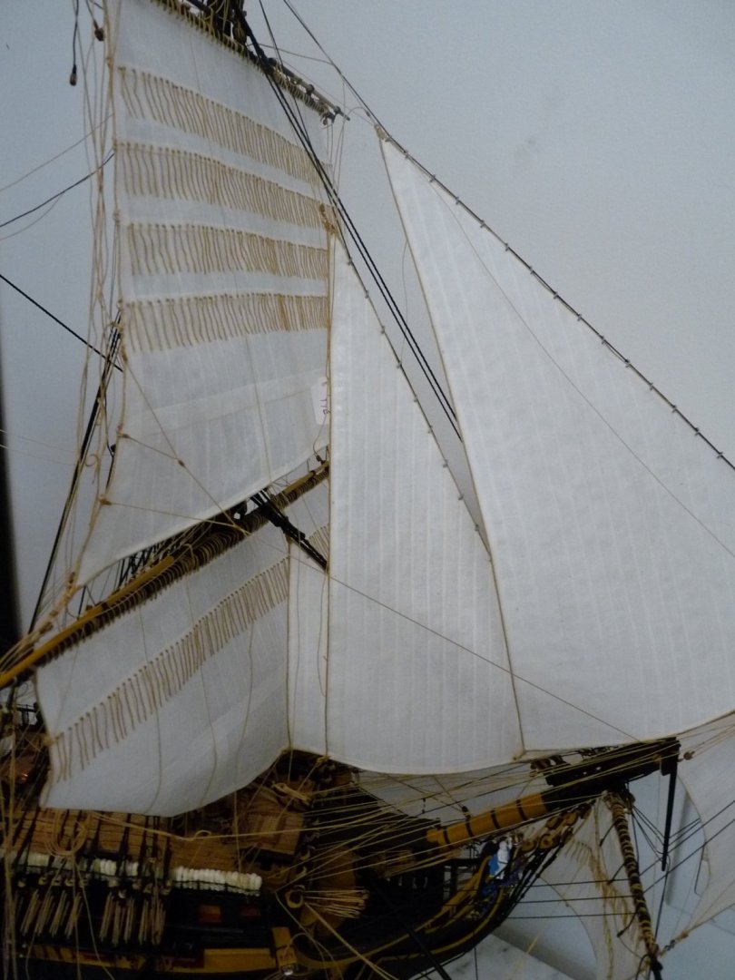
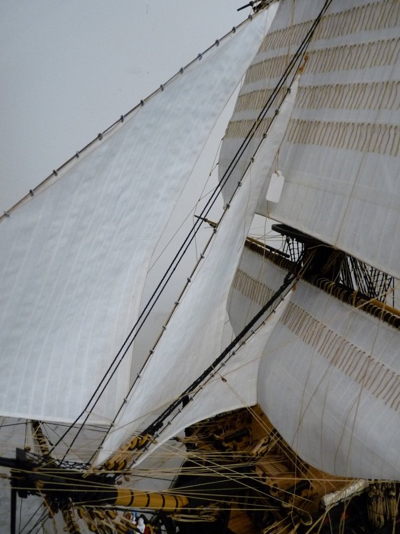
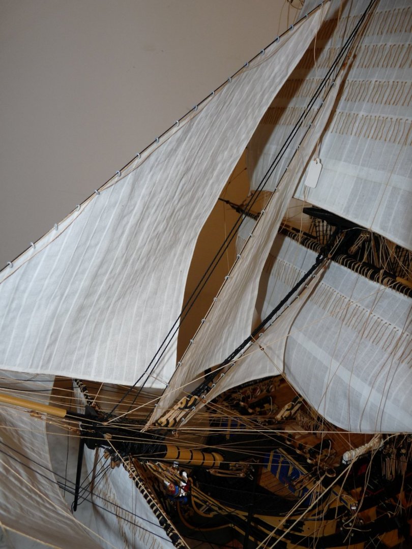
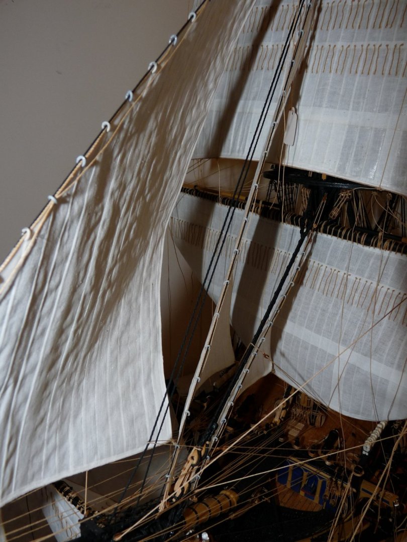
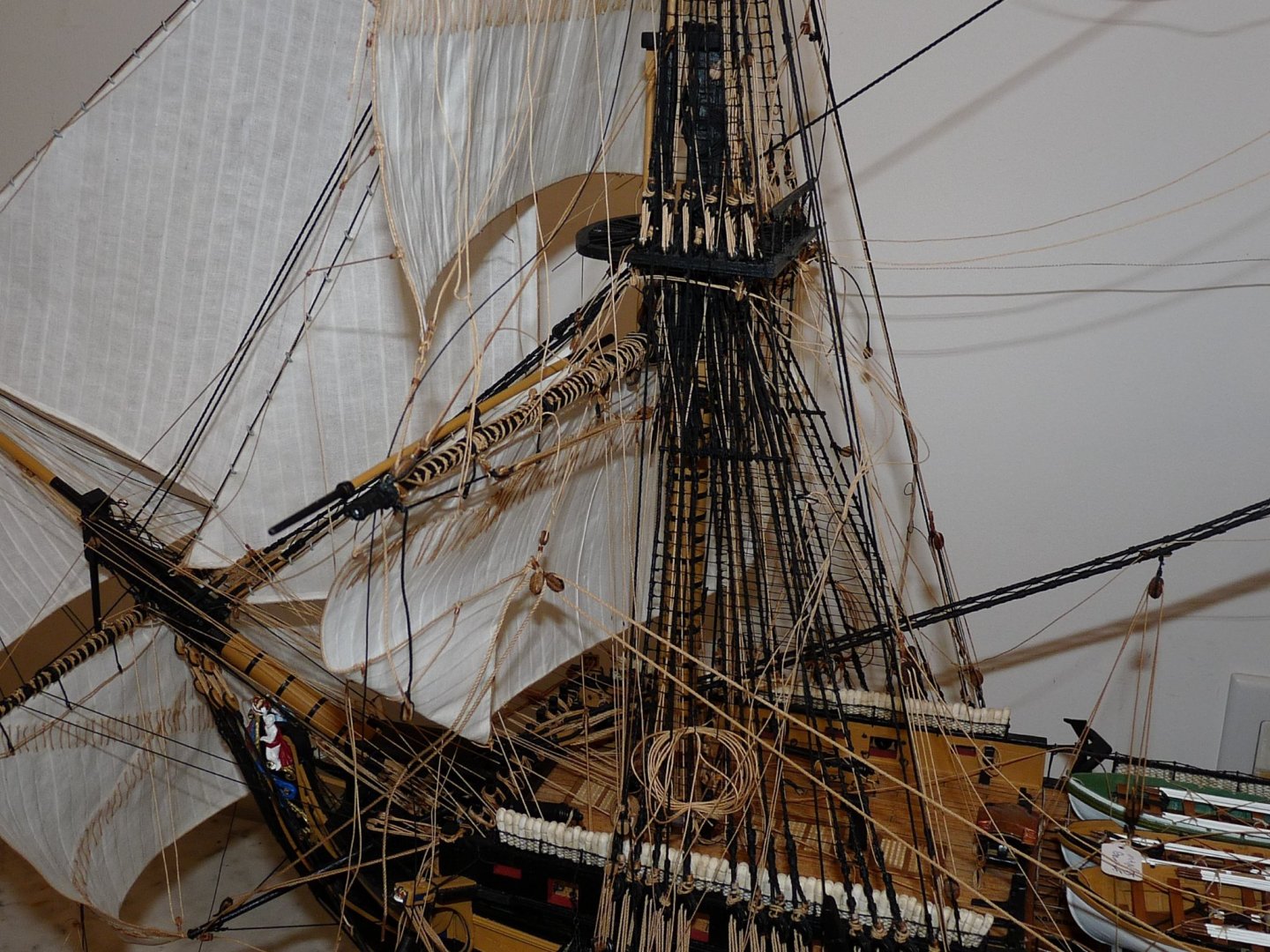
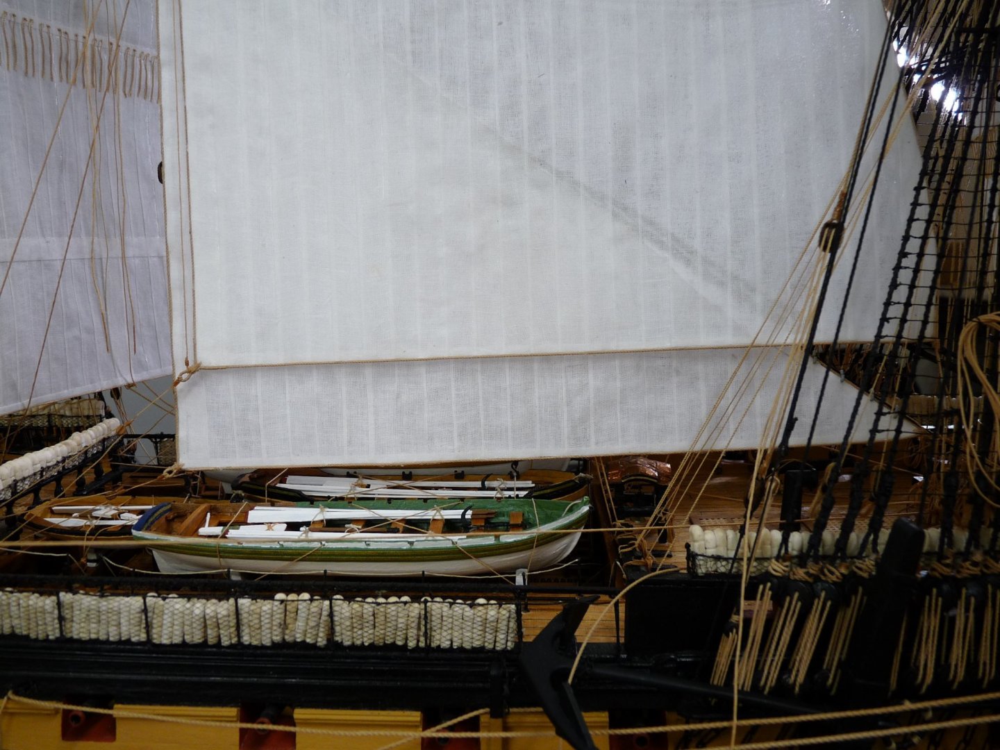
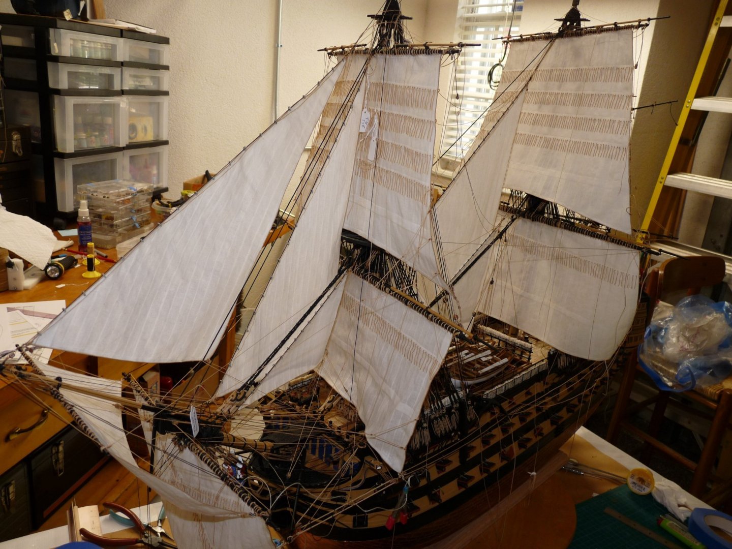
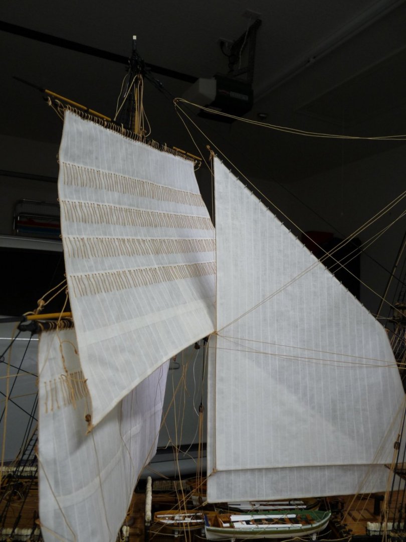
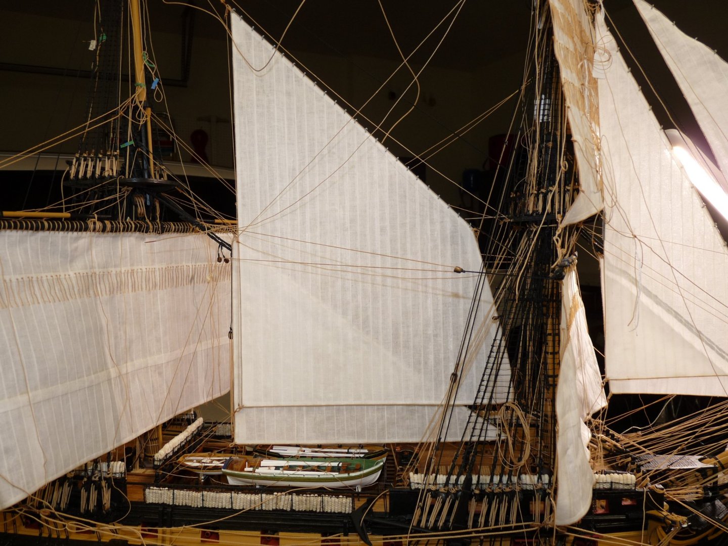
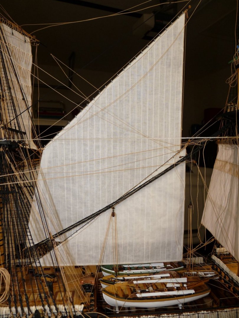
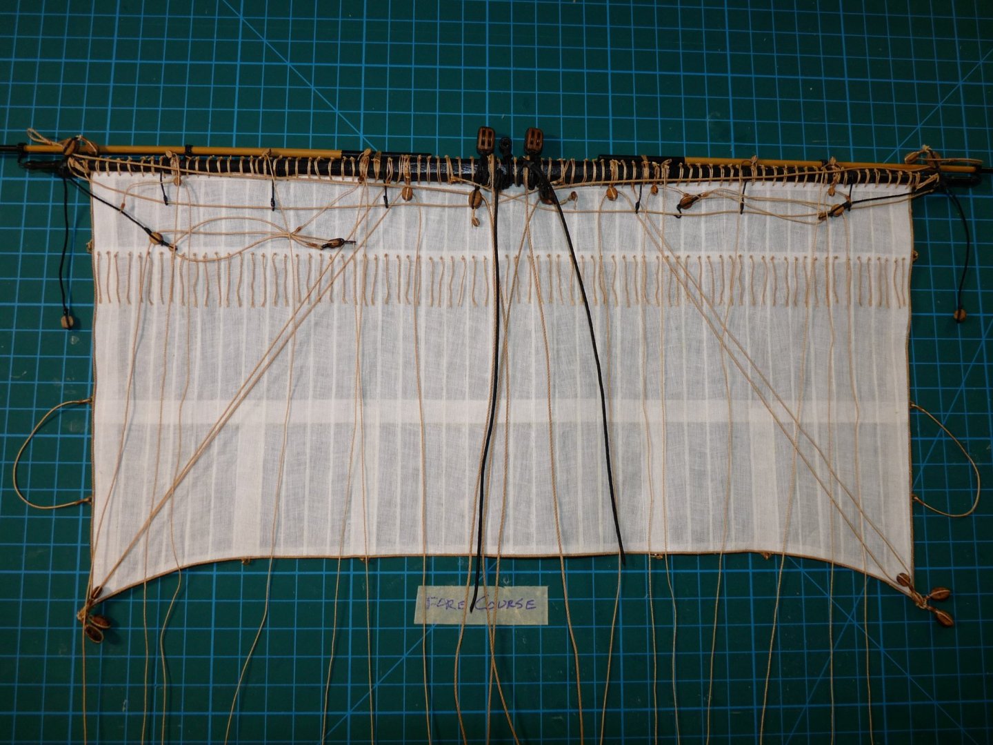
Update on Victory's re-rigging of sails following the inclusion of stiffening wires. I have now refitted and replaced all of the headsails (less the flying jib, which will be added later after the installation of the flying jibboom), the fore course and fore topsail. As I said last time, as many lines as possible have been pre-belayed at their pins or cleats, and the standing ends are tied off as the sails/yards are installed. This results in lots of loose, tagged lines hanging about, but I believe that this has saved me a lot of aggravation in trying to reach the pins on the bitts with the sails in place. I was hoping that the sails would look more like they are drawing with the wind, and think that the result of adding the wires is a great improvement. I still have to remove/refit the main course and main topsail, then replace them and the refitted main staysail and main topmast staysail to be back where I was in July when I decided to rip things apart. The spritsail and sprit topsail were salvageable as they were, so I didn't have to rework them. Still a few unsecured lines hanging about, mostly for the fore topgallant hamper, which is yet to be put in place.


-
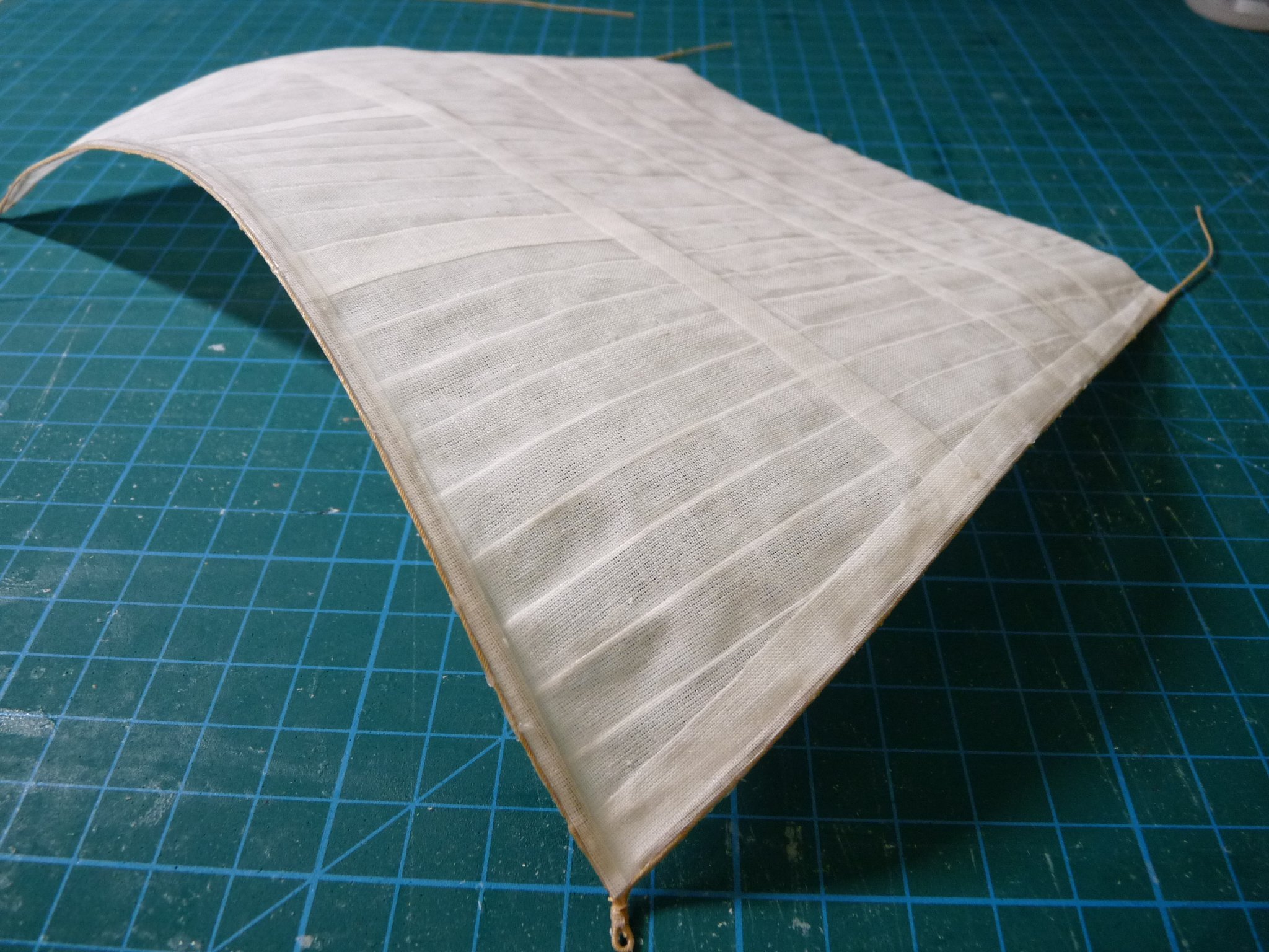
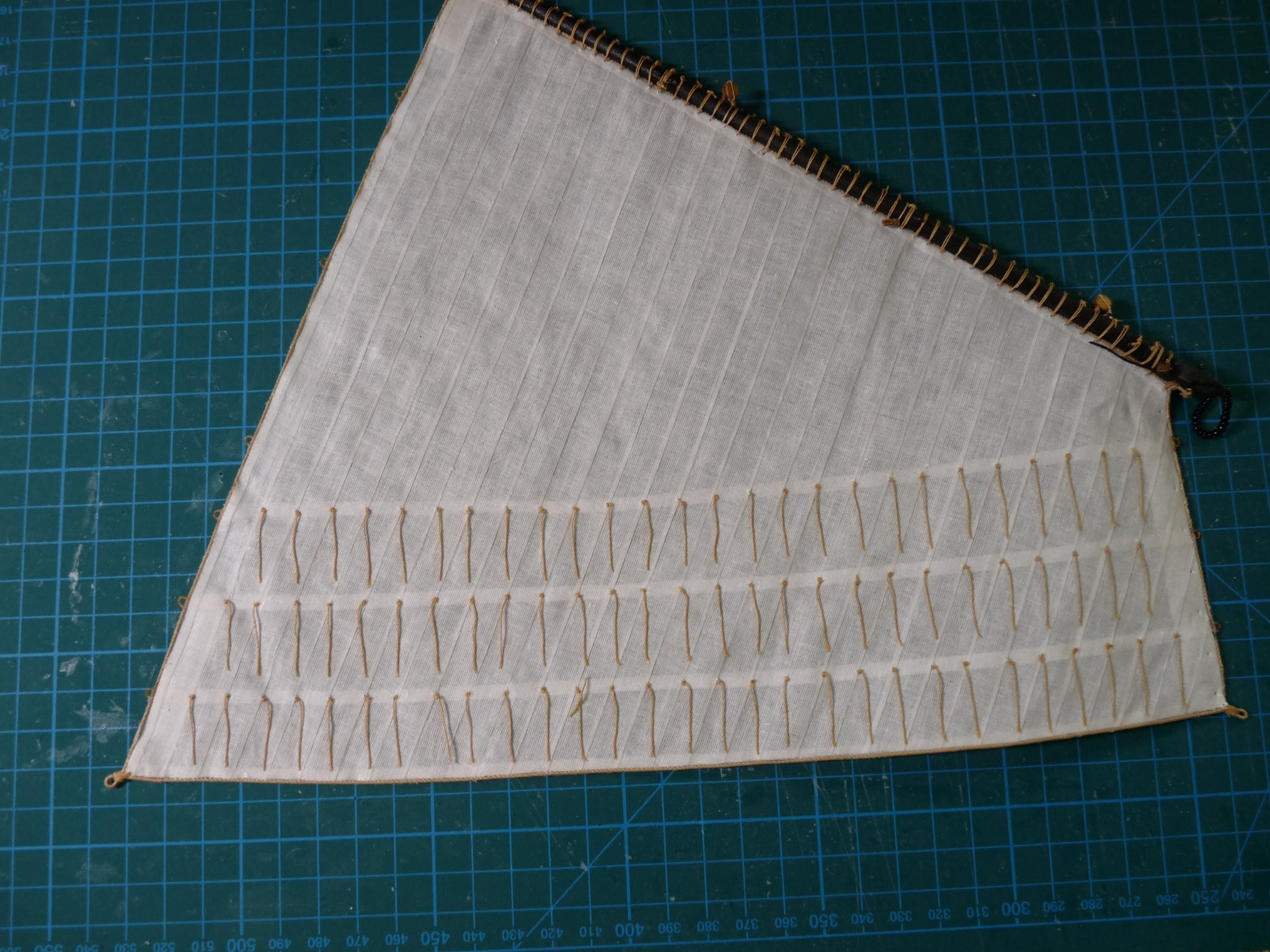
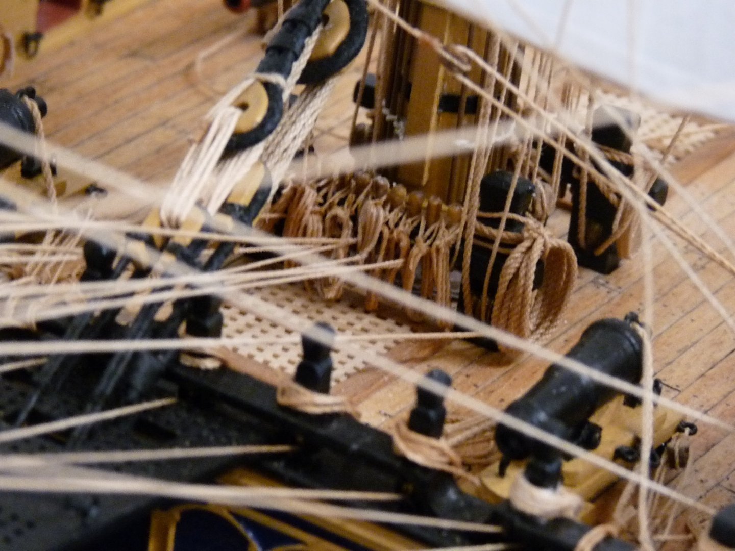
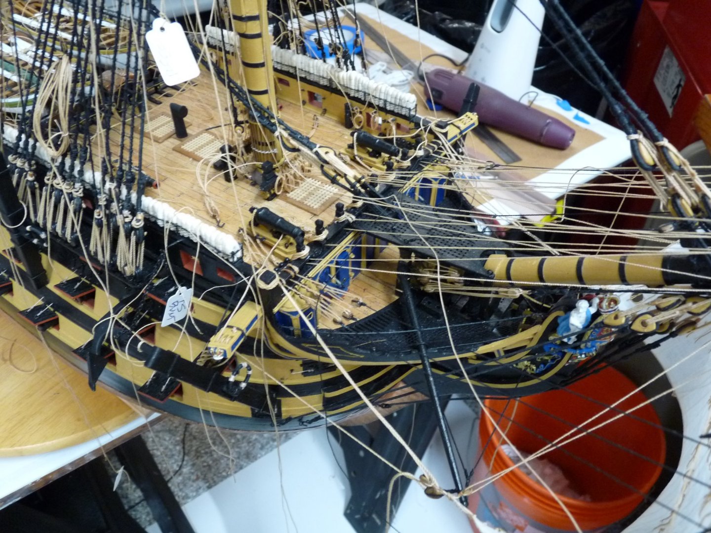
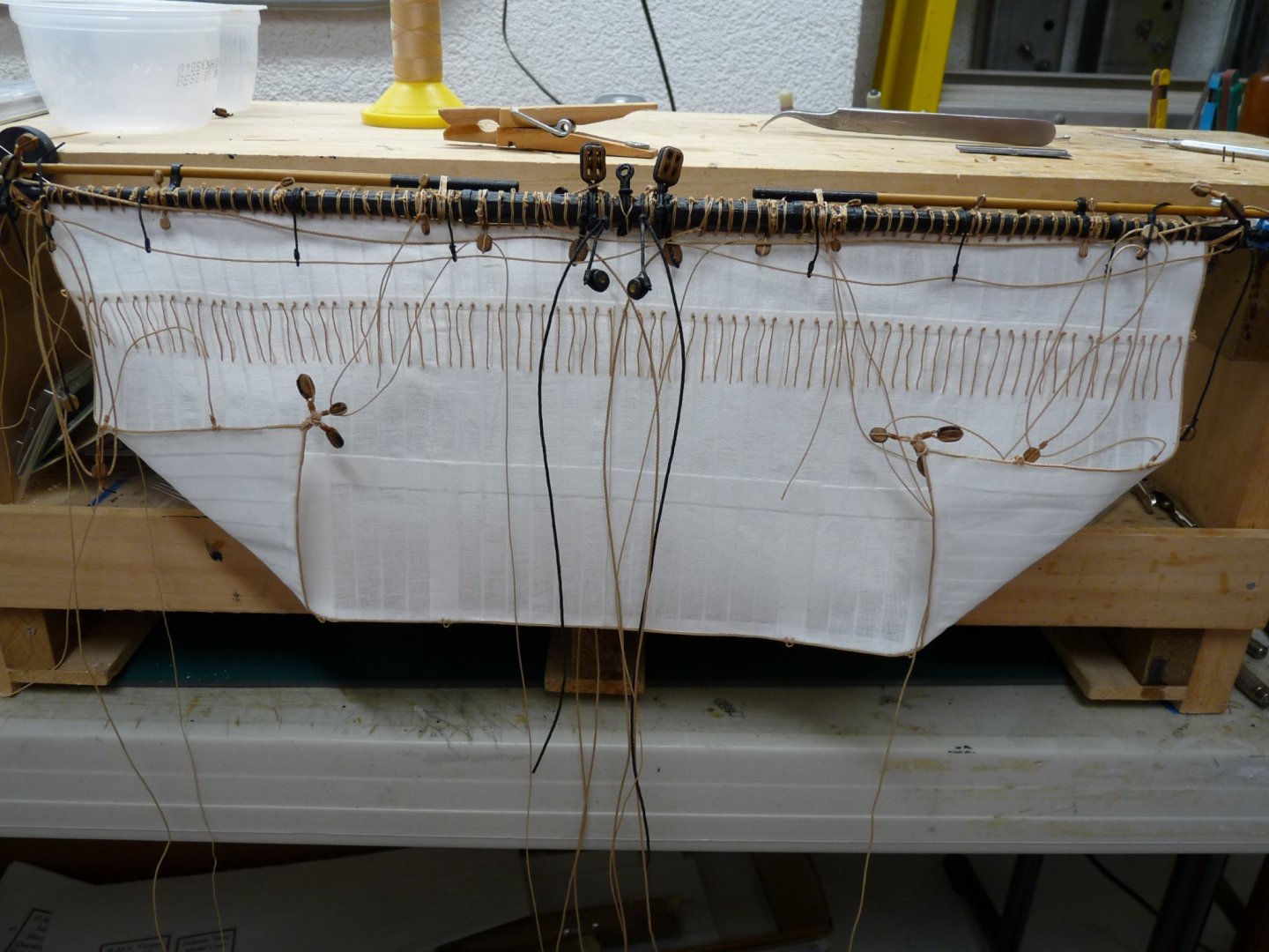
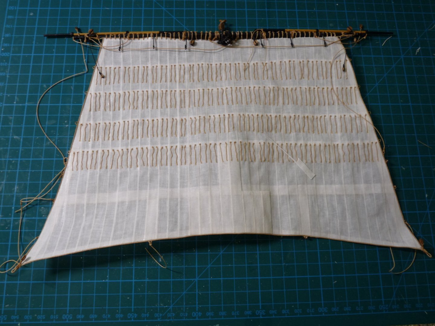
Update on Vic sail replacement: This was a couple of weeks ago, after I had removed the most of the old sails to rework or replace them with ones that have had the stiffening wires added. Some of the old running rigging was salvageable, but most will need to be replaced because the lines are now too short to reuse. I found that, when originally working around the foot of the fore mast with the fore course in place, the access to the belaying points was severely limited, using up about a month’s worth of cuss words. This time, I’m trying something different – I’m going to do the belays first, and take up the slack at the standing ends as I add the sails and spars. This results in dozens (about 80 or so) untethered lines hanging around and tangling up with each other, but I believe that in the long run it will be better – we’ll see! Here's a shot of the replacement fore course (after side), with the stiffening wires installed along the foot and leeches. The clews are raised up a bit here, they will be shaped better after the lines have been run and made taut. Reeving the jeers, loosely. A little more snug. Will update again in a few days as some of the rigging lines have been routed.


-
HMS Victory belaying anomalies
tedrobinson2000 replied to tedrobinson2000's topic in Masting, rigging and sails
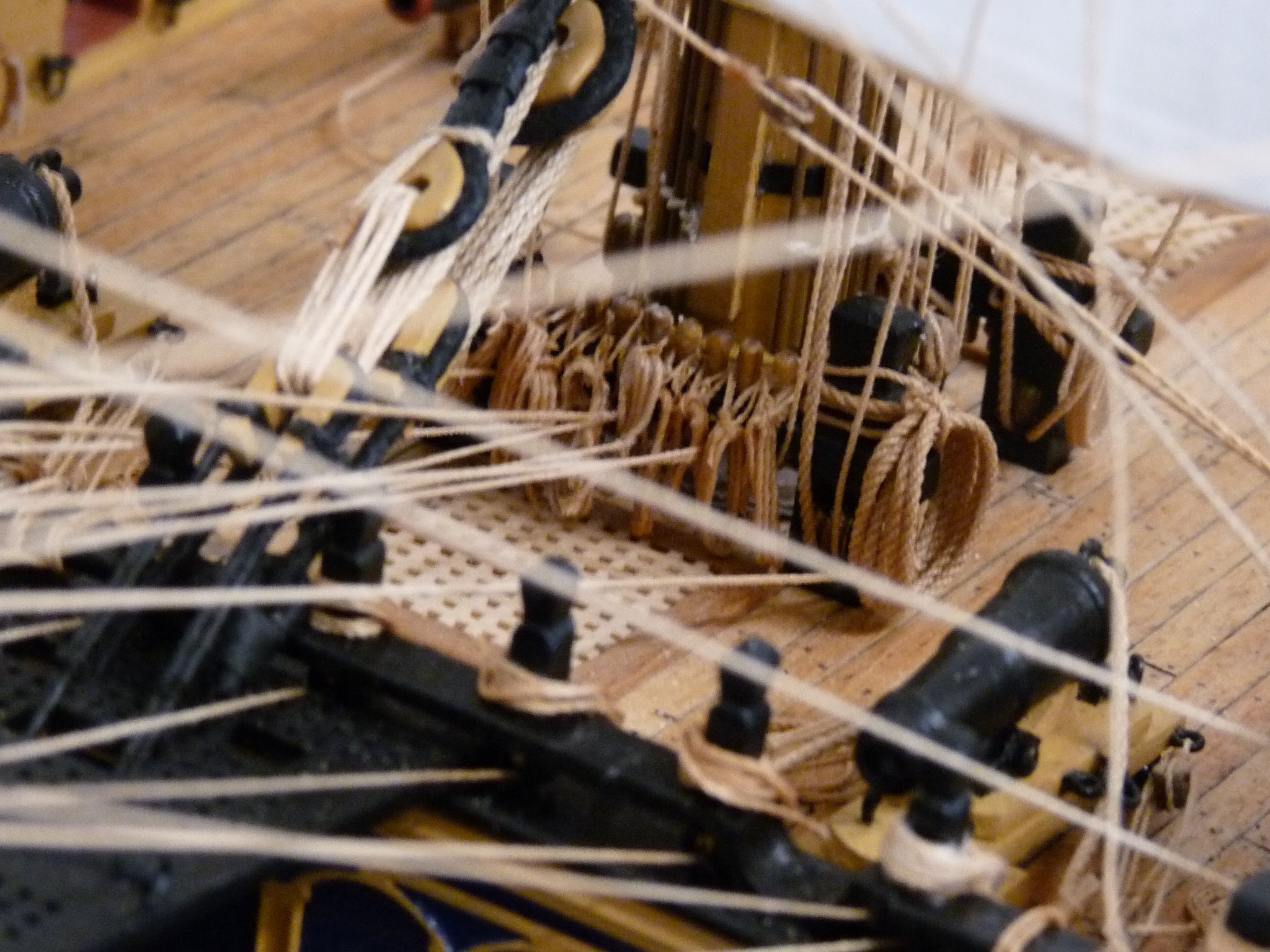
Allan, Thanx for the picture; it's quite helpful. Especially the jeer falls. The port fall is coiled over the bitt pin, while the starboard fall is frapped and lying on the deck. It looks like both methods may have been used in the day. This model has no gratings just abaft the main topsail sheet bitts, unlike Victory, It would seem that a bundle lying on the deck would have been a trip hazard, especially at night. I'm just going to send the running ends of the jeers down through the gratings to the deck below for stowage. The photo also shows the focs'l breast beam assembly and its belayings quite clearly. Like this model, Vic also has 4 timberheads either side of the belfry. I added sheaves to each of the timberhead knees, but unfortunately I already have 10 lines that belay to the 8 timberheads, so I need to find additional belaying points. I have already doubled up on the fore course buntlines at the breast beam, but need to secure several more lines in the vicinity. That's why I'm trying to determine how the seamen made lines fast to a rail without having timberheads or belaying pins available. I'll probably just use clove hitches at the rail, and let it go at that. -
HMS Victory belaying anomalies
tedrobinson2000 replied to tedrobinson2000's topic in Masting, rigging and sails
Allan, Thanks for the tip from Lees. I actually have a copy of Lees, but missed that section on belaying the topsail braces. I did end up belaying them on the breast beam rail, but (as per my original question) was not sure how the actual belay was made in the absence of belaying pins there. Still not sure how this was done back in the day! Ted -
HMS Victory belaying anomalies
tedrobinson2000 replied to tedrobinson2000's topic in Masting, rigging and sails
I agree, Ian. on the model I'll just belay them to the focs'l breast beam rails, or to the belfry, or some other logical place. I enjoy trying to understand how 18th century sailors did things in their everyday lives. I've come to the conclusion that their lives were not as romantic as it seems from a viewpoint 250 years in the future, but full of danger and deprivation. Just little things, like how they handled belaying lines, interests me. These things are easy to do on a model; not so much in real life, I believe. I try to picture a sailor, many days at sea from being a lubber, attempting a topman's duties for the first time on the footropes of a main yard 4 or 5 stories above the deck (twice that to the sea) on a dark and stormy night. A fall would almost certainly result in death or crippling injuries, or drowning. Life must have been fairly cheap if you were a hand. Even more certain if he was working a top or topgallant yard! -
HMS Victory belaying anomalies
tedrobinson2000 replied to tedrobinson2000's topic in Masting, rigging and sails
Popeye and Ian, I think that unreeving the cat falls would have been very inefficient. I guess that if the ship was to be on a long ocean voyage (away from shallow coastal waters) it would be possible, but just begs the question since the falls (both bower anchors?) would need to have been re-rove when the need for them was again anticipated. Normally, they would be left catted, and removing the falls would have been a pretty big job, and all just for relieving the need for stowage? My guess is that they just coiled the falls up and hung them on a shroud or other convenient out-of-the way spot, even though the focs’l was a rather congested area. That being said, I have never seen a model that displayed the cat falls stowed this way, so it’s just conjecture on my part! How about another anomaly? Both Caldercraft and in McKay’s AOS, the fore top yard braces are shown to be belayed in the waist on the second skid beam of the boat tier, in between the boats. This seems not to be very efficient in that a sailor would have had to climb over and between the stowed boats to even reach this point, and then would have had no room to haul on the line, much less having room for the other dozen or so hands needed to haul. Seems like the top yard braces would have been in constant need of adjustment, especially when tacking. There must have been a better way to belay these lines. Any ideas? Regards, Ted -
HMS Victory belaying anomalies
tedrobinson2000 replied to tedrobinson2000's topic in Masting, rigging and sails
Allan and Popeye, thanks for the replies. Allan, I re-ran my calcs for the fore yard weight, and using dimensions found in McKay, I get about the same results as I posted before. I used 89’ for the overall length, with a 22’ long central (assume cylindrical) section of 1’-9” dia (without adding the batten thicknesses). This leaves the two end sections each 33’-6” long; major dia = 1’-9”, minor dia = 9”. I get 53.5 cu ft for the center section, and 44 cu ft for each of the outer sections, for a total of about 140 cu ft. I used the density given for fir of 53 lb/cu ft., which yields a little over 4600 lbs. Then add the lower double jeer blocks (which were massive, probably several hundred pounds each), and miscellaneous fittings such as stuns’l irons, bunt, clue and sheet blocks, etc. and it would not surprise me if the total weight that needed to be raised by the fore jeers was way over 5,000 pounds! Not to quibble, but the darn thing was pretty heavy!! As to the stowage of the jeer falls, I again note that each would have been about 250’ long with the yard raised, and were 7-1/2” lines. Popeye, as to making hanks and hanging the excess on the falls, it may do for smaller ships, but 250’ of 7-1/2” line seems way too much line to have been done this way on a first rate. It seems easier to send the unused line below, through the gratings, to the upper gun deck for stowage. I believe, that once the lower yards were hauled up, probably at the shipyard at first, they were not lowered again very often, if ever. The upper yards were frequently raised and lowered to shorten the top and topgallant sails, but I doubt if the course yards were moved very often. Thanks to both of you for ideas regarding tying off to a rail. The photo that you sent Allan, is a little fuzzy, but it looks like they are using a simple clove hitch, as Popeye suggests, or a similar knot. This is how I handled these lines originally, before I ripped them off to re-make my sails and redo all the fore rigging, but it doesn’t seem very practical. If one had a slack length of say 50’ on a line, a clove hitch would require the bitter end to be sent around the rail 3 times, each time running the whole 50’ of slack around the rail. A lot of work, and especially hard to deal with if the line needed to be freed up on a dark and rainy night. My guess is that if they took a say 15’ bight over the rail, it could then have been made up into a clove hitch to secure it, but I haven’t been able to find an example of this anywhere. Curious! Here’s another, similar question. What was done with the excess cat fall lines? The cat blocks on a first rate were triple, thus for every foot gained in raising the anchor as it was hooked on near the hawse holes, 6’ of line was gained on the cat fall. From the waterline to the upper position where the anchor was catted, is about 40’ or so, so the excess line would have been over 250’, including the excess needed for the hands to get a purchase on it to haul. Jotika says that the excess was coiled and hung on the cleat mounted on the outer, after side of the cat. This, again, seems curious to me. That would require a sailor to go out on the cat itself to hang the coil, and it doesn’t seem as if it would be very secure hanging there, and subject to being washed away in heavy seas. Any suggested solutions are appreciated. Regards, Ted -
HMS Victory belaying anomalies
tedrobinson2000 replied to tedrobinson2000's topic in Masting, rigging and sails
Hi Allen, Nice to hear from you. Thanks for the lead to Longridge, I've just ordered a used copy, even tho I already have about 6 books specific to Victory. I would be very interested in seeing an example of a line being tied off to a rail, and what knots/bends are used. Can you lead me to a photo or drawing of one? Here's another question. How did they raise the lower fore spar into position? It's easy to visualize raising the main yard, as the jeers (2 each) run down through openings in the quarterdeck to the upper gun deck, through sheaves in the fore brace bitt pins, then can be led to the main capstan where dozens of men working the bars can raise the spar to its desired height to be lashed to the slings. These fall lines are quite large; 7-1/2" (circumference) or so. I've done a quick calculation for the weight of the fore yard, using dimensions from McKay and the nominal density of fir @ 500 kg/cu meter (spruce is about the same- don't know what wood was actually used in making up spars) and I get about 4,500 pounds without cleats, blocks etc. This would make the total fore yard weight, without the sail bent on, at about 5,000 lbs. The main yard would have been even heavier, but had the advantage of being nearby to the capstans. I note that with the triple jeer blocks, the mechanical advantage is 6 times, so the weight raised is about 415 lbs per jeer fall, which I guess i doable with 8 to10 men per fall. The x6 advantage in the triple sheave system comes at the expense of having to pull 6x the length of rope to raise a certain distance. The fore yard lies about 40 feet above the deck level, so each jeer fall will have to have 6 x 40 = 240 feet of line, plus the slack used by the men to haul on. So, the question, after all that, is: where is all this line stowed? There's no room on the focs'l deck for this much slack line, I have just sent the ends down to the upper gun deck through the gratings that are near the bitts. Any idea what they actually did with the extra line?? -
I’m in the throes of rigging my Caldercraft 1:72 Victory, and have run up against some oddities. I am adding a suit of sails to the model, which was not intended to be the case by Caldercraft. One of the first stumbling blocks is the lack of belaying points for the 4 tri-sails forward – the fore staysail, fore topmast staysail, jib and flying jib. They each have 2 sheets (port + starboard), a downhauler, a tack and a halliard as a minimum. Additionally, the tacks of the jib and flying jib are mounted to sliding travelers that require outhaulers to position them along the jib boom and flying jib boom. Each of these lines need belaying points. The double sheets on all but the flying jib are rigged with tackles, thus requiring 2 attachment points each – the standing parts of these 6 tackles presumably attach to eyes and the running ends to cleats. None of these points are called out or shown by Caldercraft. I note that shown in almost all old photos, as well as drawings by McKay and also by McGowan in his book “HMS Victory”, and also by contemporary videos of walk-throughs on the current Victory, there are 11 or so timberheads on each of the focs’l rails that presumably would have been used as belaying points for some of the lines. My presumption is that for some reason, Caldercraft omitted these timberheads from their model, even though it is touted as being the most accurate one on the market. If those timberheads, which I presume are extensions of the frames and are not easily removed or replaced in actuality, were included on the model, the focs’l hammock nettings would have to move outboard to accommodate them, and the channels would also have to be wider for the fore shrouds to clear. Very curious!! Does anyone have any suggestions as to why this is the case?? This raises another question, in that several of these lines have to be somehow tied off to the beakhead bulkhead fife rail, as well as to the focs’l breast beam rails. There are not enough sheaves nor timberheads to accommodate all of these lines, so I presume that they were just tied off to the rail, but I have not seen a way to do this neatly. One way would be to run the bitter end of the line around the rail several times then hitch it off to itself, but that would not be very practical for long lines, nor shipshape. Perhaps a bight was formed, passed around the rail and then hitched off. I wonder if anyone has run across these problems, and what the solutions are. I have some more questions regarding the fore jeers, as well as the cat falls, but will save them for another post. Thanks, Ted
-
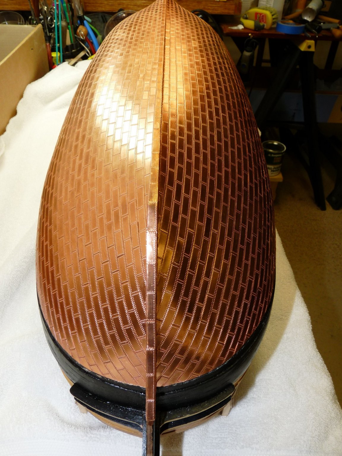
Very nice job, Will. The hull looks great; I like the patina. I also did the rudder when I plated the hull, but still haven't shipped it - was afraid of damage while handling the hull. I'll add it as one of the very last jobs as I complete the model. Don't forget the pintels while you still have the hull upside-down - they will be harder to do later on!
-
Thanks, Mort. I know that what they would probably have done is to bend a new line to the old one using a sheet bend, but I'd like to avoid that if I can because it will show. As long as I'm going to all this trouble, I'll probably just rig new ones where they are needed.
-
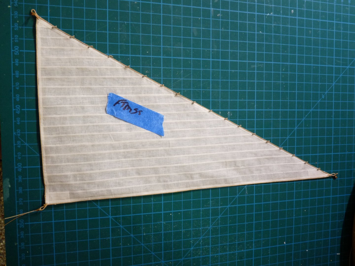
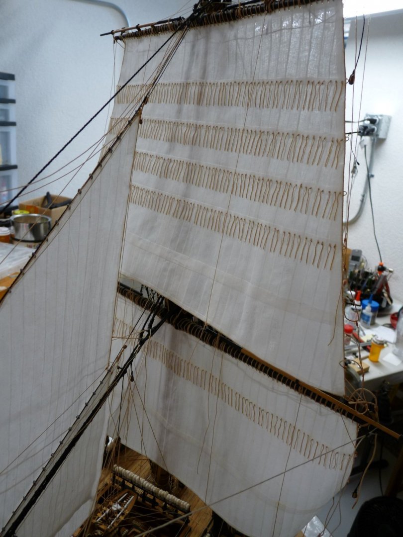
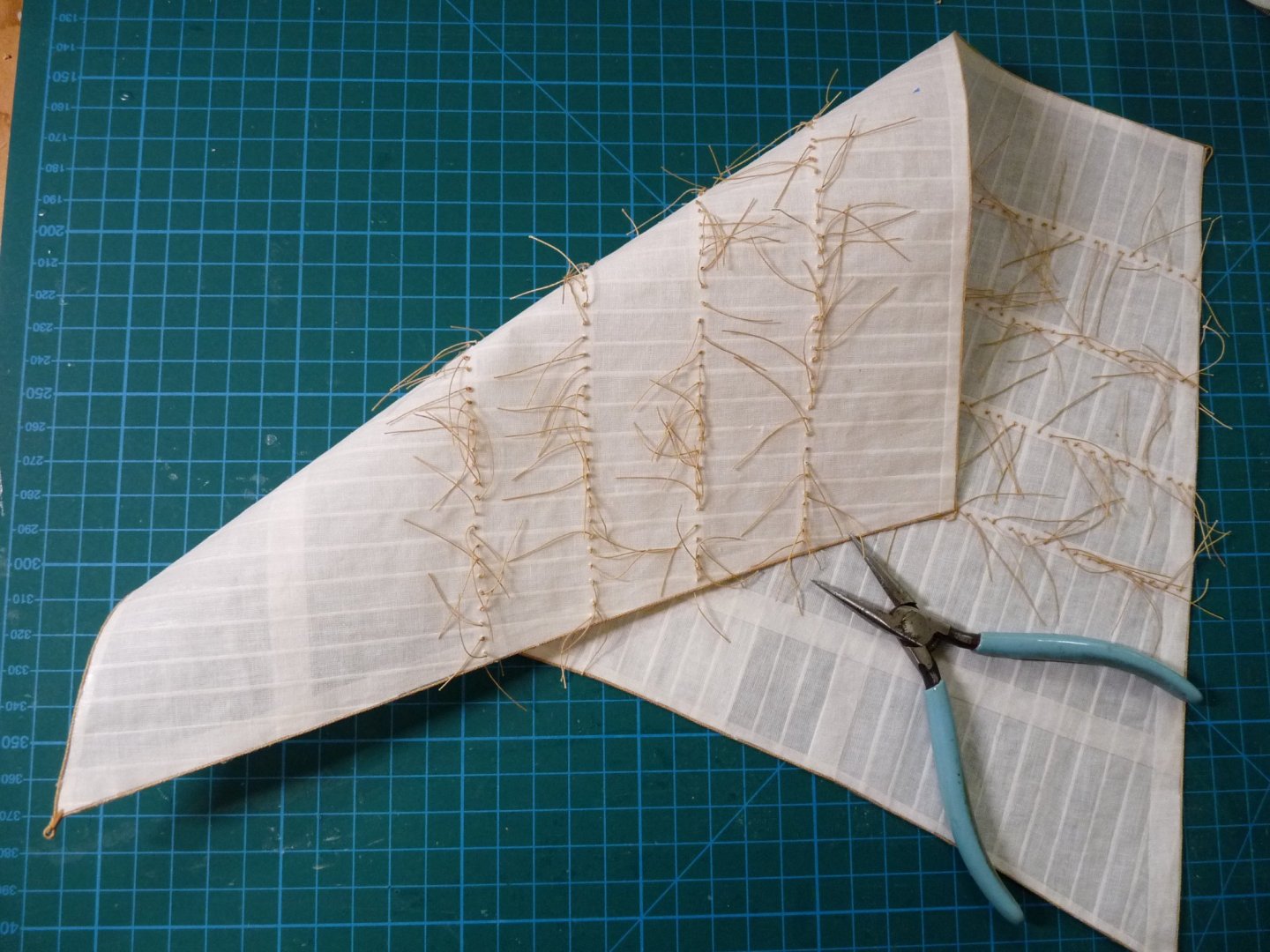
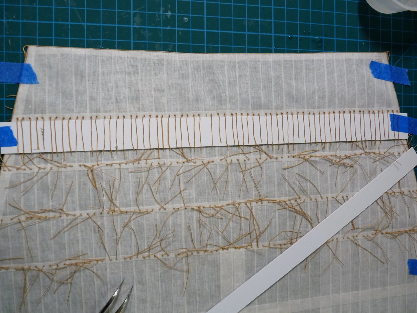
Thanks for the kind words, OC - and thanks to all who have looked and "reacted" favorably. I have now removed all the fore-and-aft sails (4 stay sails + the jib), plus the fore topsail that I had previously mounted. Still have the fore course, main course and main topsail to remove. I will add stiffening wires to the leeches and feet of these sails as I remove them, and then rehang them - a not trivial task!! I'll probably have to remake a lot of rigging line, because the ones that had been installed and belayed will now be too short. I think I can get away with replacing most of the rigging lines, but am still unsure how to handle the main yard jeers, as they were previously belayed below decks - now that the quarterdeck in is place, the belay points are inaccessible and the existing jeers are too short. The loose rigging lines now look like a rat's nest!! The rework means removing the boltropes and linings, adding the wires and then replacing the linings on top of the wires, then remaking and replacing the boltropes and cringles I have been experimenting with different types of wire for the stiffeners, trying copper, stainless and coated wire in different gauges from 28 to 20. the wires are glued to the foreside edges of the leeches and feet, and then covered by the leech and foot linings. My conclusions are that the copper and stainless are too dark, and show through the lining cloths. The best results were attained with white, covered copper wire used in jewelry-making. 28 gauge is a little too light for the larger sails, so I use 22 gauge for them and 28 gauge for the smaller sails. It's virtually not detectible to the casual eye, yet holds a curve well. Before removing the old sails, my prototype for using the wires was the mizzen topsail. Here are a couple of shots of that prototype. I have now repaired the fore topmast staysail, here are some before/after shots. Without wires- and with them. The big test will be how the courses come out; I want to show them clewed up, but couldn't keep the billow in them without the wires. Here is the fore topsail as originally made; we'll see how it handles with wires.


-
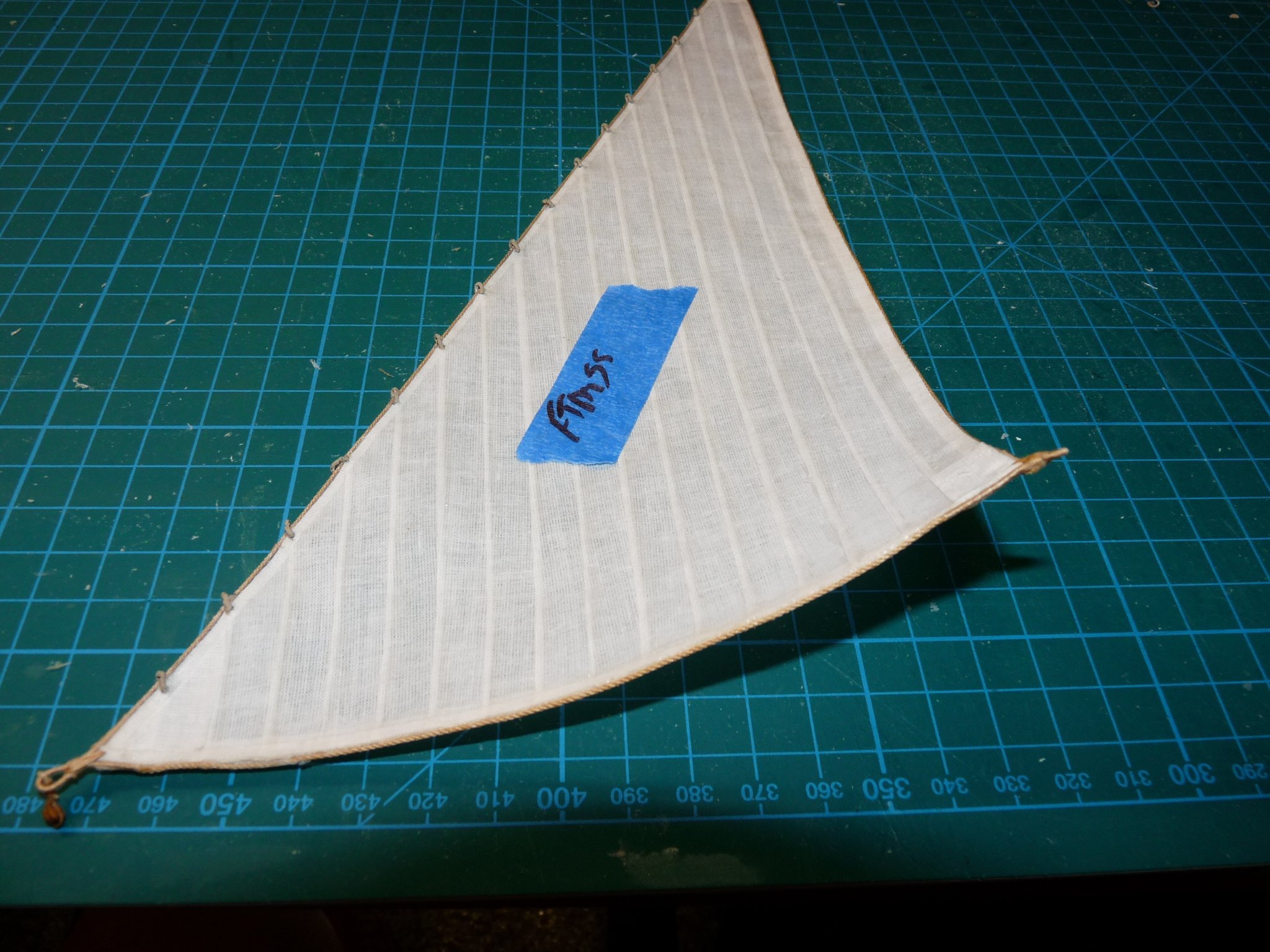
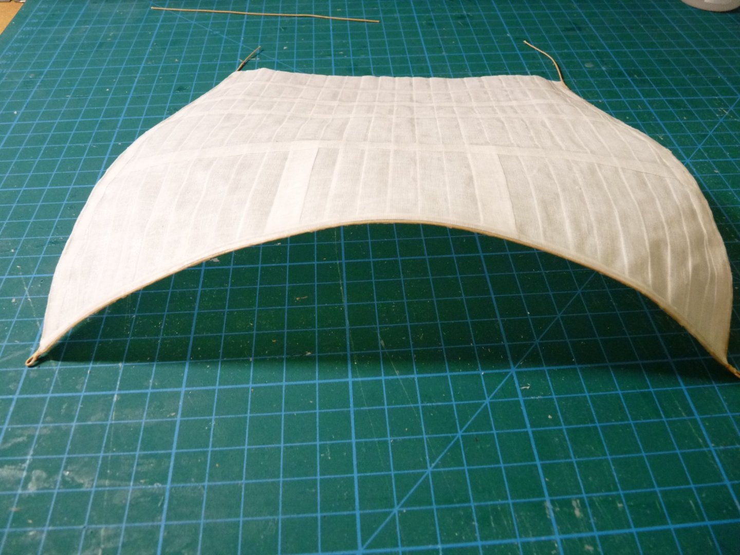
It's been a while since I have posted here. I had been making some progress in adding the mizzen sails, but decided to take small break to write up a practicum on how I made my sails, as I have gotten several inquiries about them. As I was doing so, it became apparent to me that I had made some advances since I started the sail-making process, and that I was not completely happy with my earlier efforts. In particular, I had wanted to be able to shape the leeches and feet of the sails to make them appear that they were full of wind, but the sail edges of my fore, main and trysails were not as compliant as I had hoped they would be. Also, several of them had edges that were wavy, or scalloped and didn't look quite right. I agonized over the decision to swap them out, but ultimately decided to do so. AARGH!! This means that most of the work that I have done over the last 10 months went by the board. I will also have to remake several hundred feet of rope to replace the lines I had already installed and would now be too short. Victory has 22 sails in her set, not including stunsails, which I wasn't including. I already had 11 of the sails made (the more difficult ones!), and having to remove and rework or replace them is daunting. I have learned a better way to add the boltropes that avoids the waving/scalloping effect (which was due to the rope shrinking in length as it was wetted by the PVA glue), and found a way to invisibly include thin wires to the leeches and feet to hold the curves. I hope that the result of reworking them will be worth the effort. Cutting off that first sail was nerve wracking, but now the die is cast, and here we go! Will post occasionally to show my progress.
-
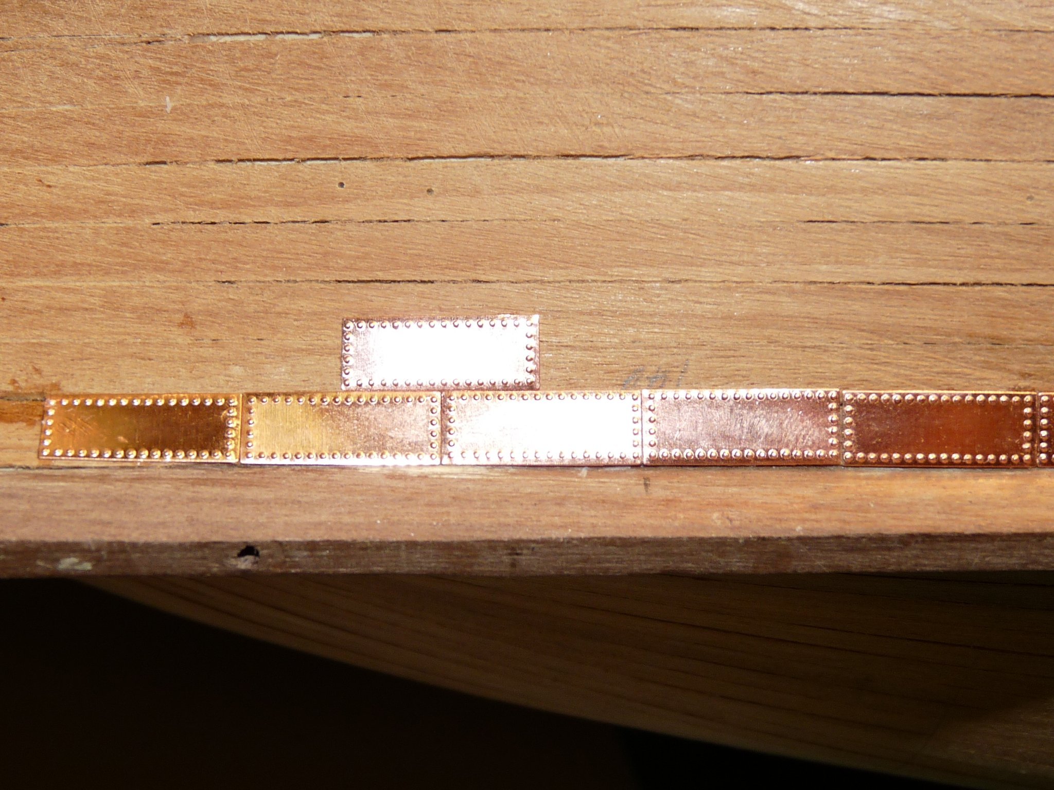
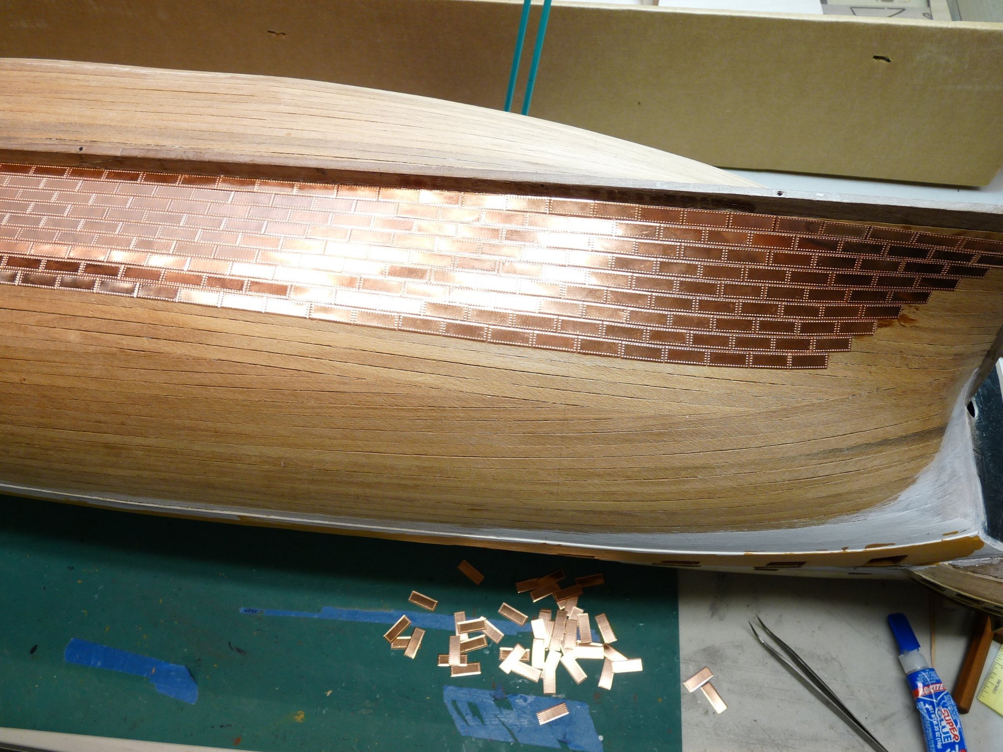
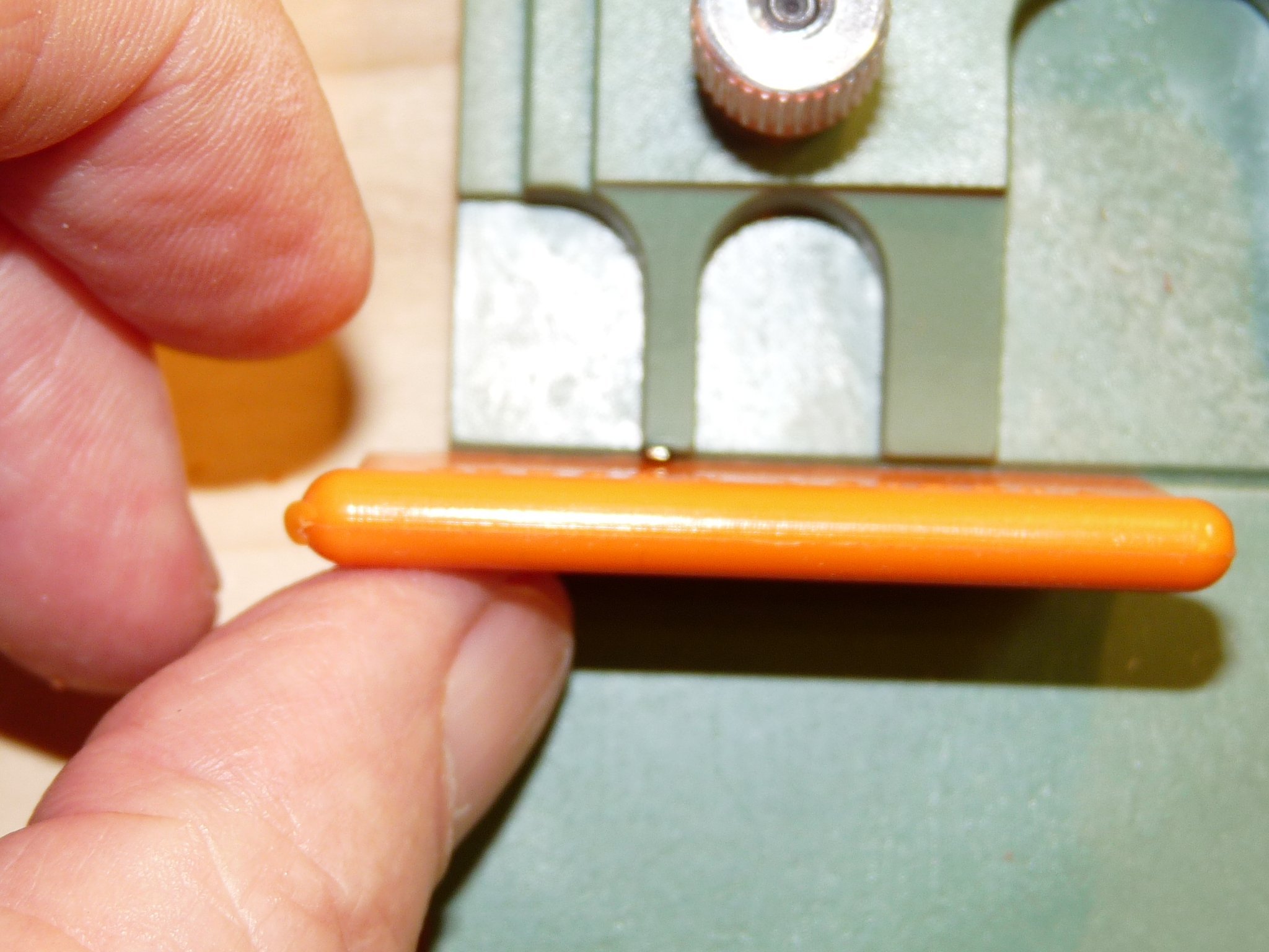
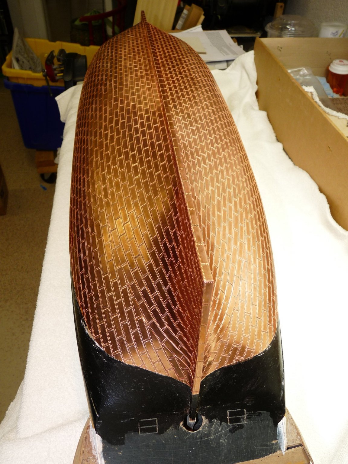
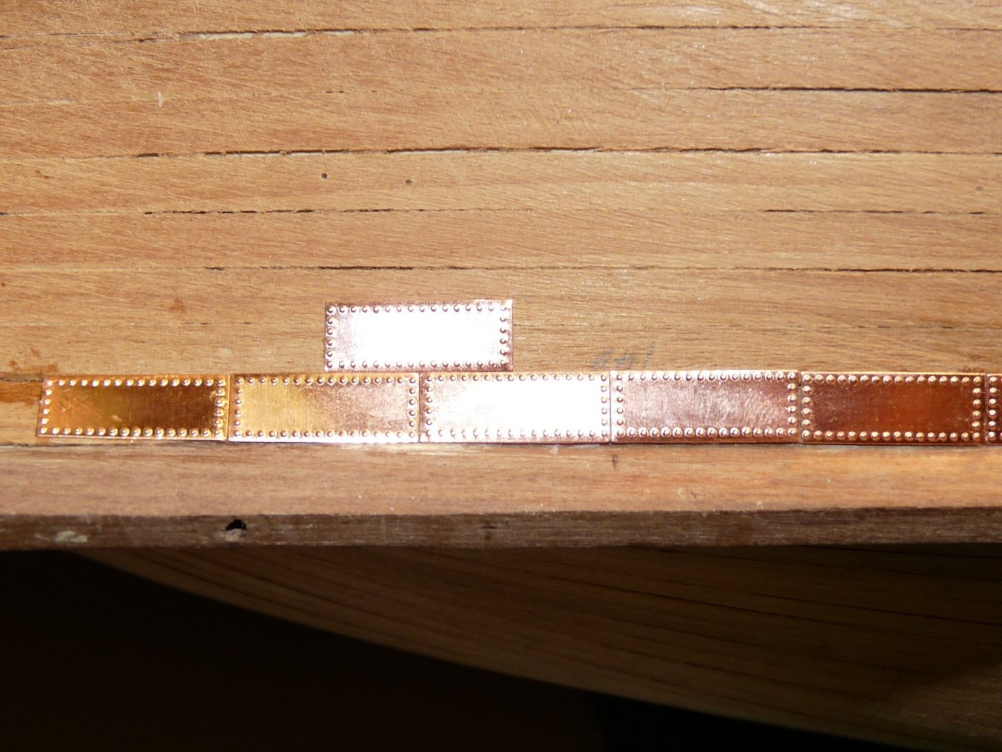
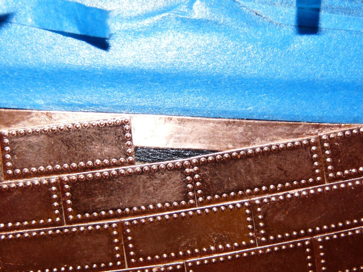
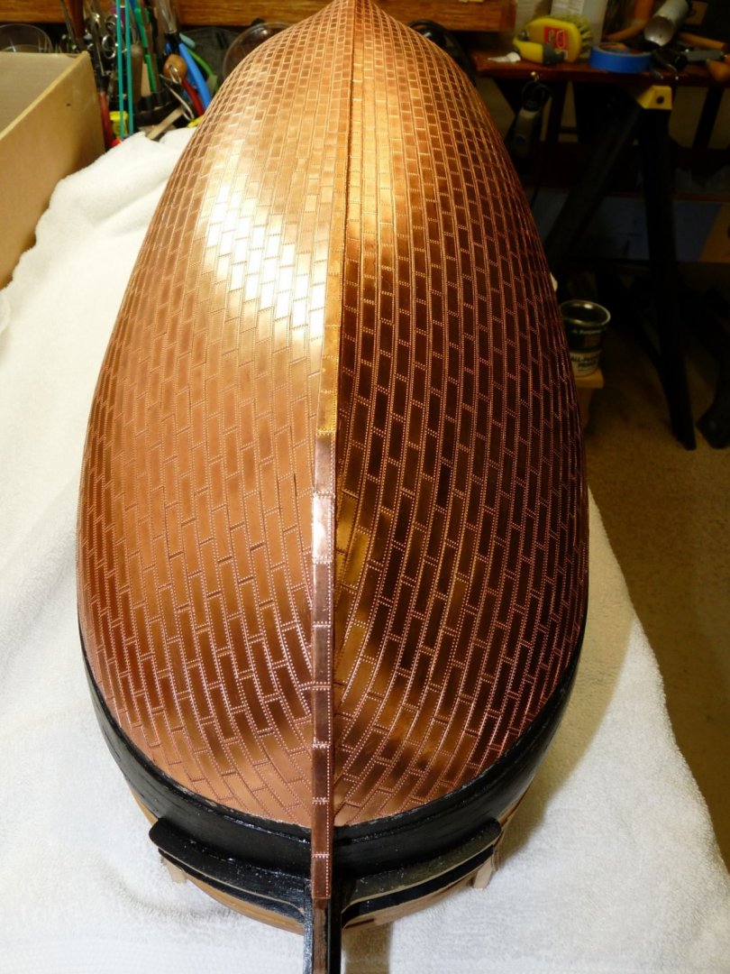
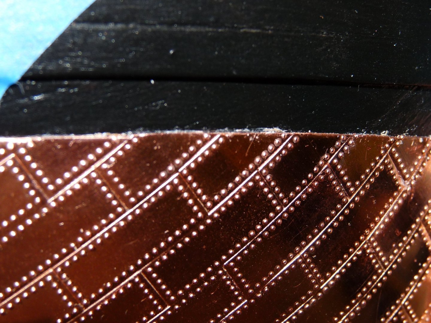
Hi Will, Nice to see your progress, your Vic is looking super. I wrestled with the tiling also, and here are a few tips. I used CA Gel, which gives about 20 sec of time to locate the tiles exactly before it grabs. Just used 5 small drops/tile - 1 at each corner and one in the middle; glue placed on the hull not on the tile. Careful not to use too much so that it oozes onto the surface. Started on the garboard plank, adjacent to the keel as it had a nice straight line to follow. Just apply them in a staggered pattern like laying bricks. To do the keel, I used a Mission Models bending jig to get the 90 deg bends straight. The plates are the right size to cover the bottom of the keel, plus one face. The other face of the keel can be done with trimmed plates. Work up to the waterline. When nearing it, I added a strip of copper tape used for stained glass work, letting it overlap the waterline. This will hide any small missing corners of tiles if they appear. After adding the tiles to cover the waterline, apply a piece of tape and mark the finished waterline on it, then, using a very sharp Xacto knife, trim the tiles to the marked waterline. Although I didn't do this, you can try to represent the rivets on the exposed edges of the trimmed plates. Keep up the good work!!


-
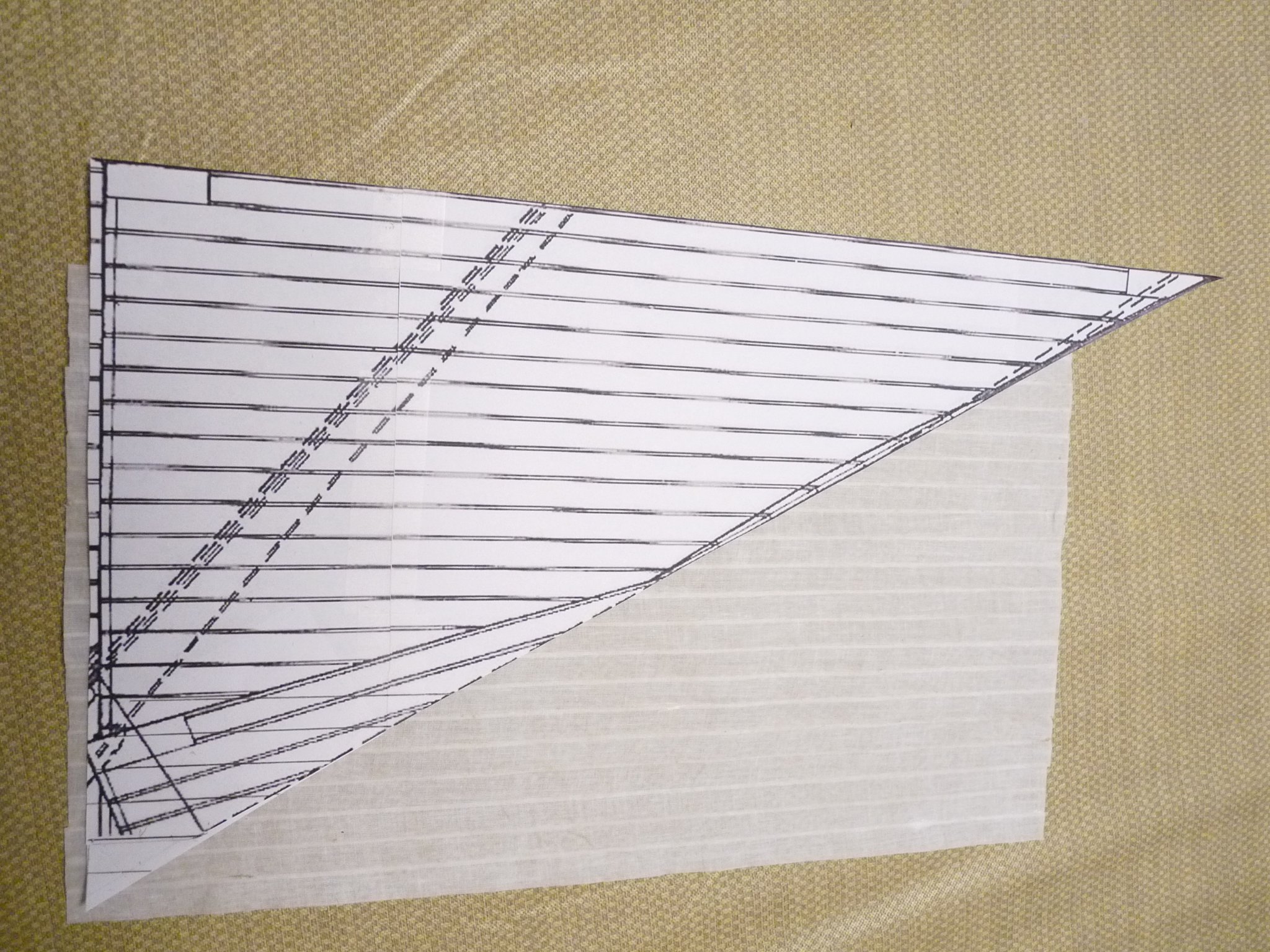
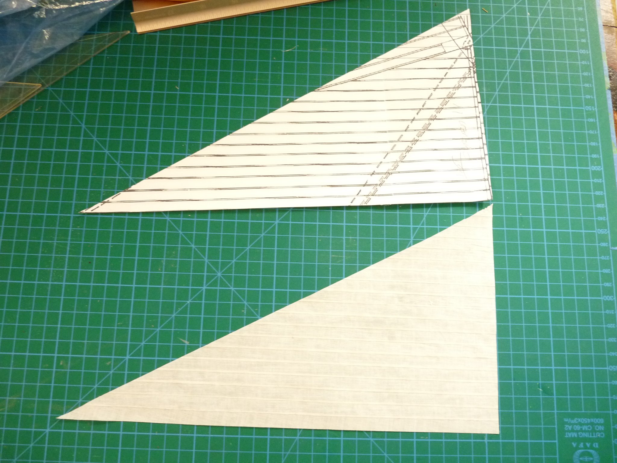
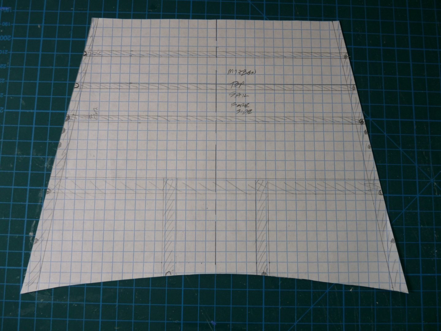
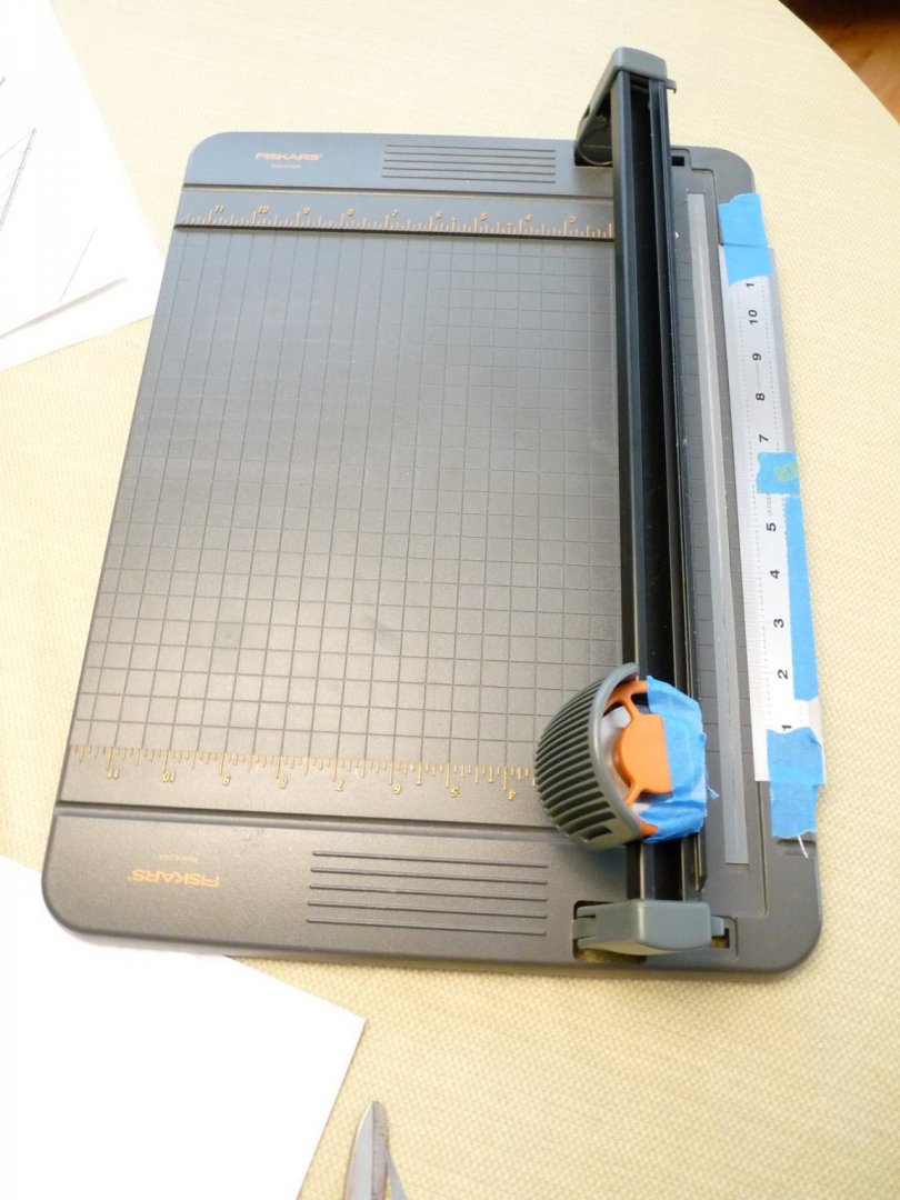
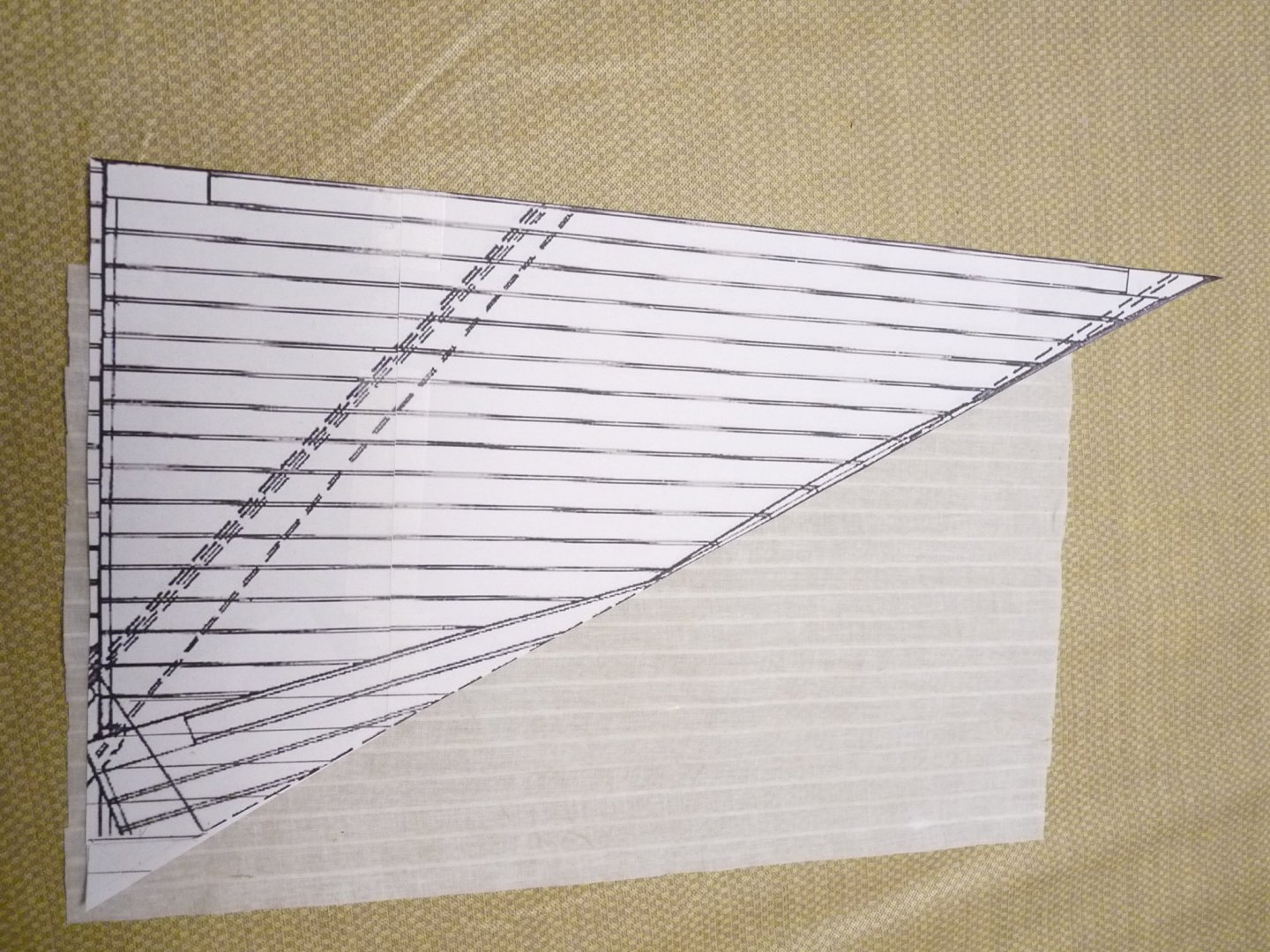
Just a brief update on my progress. I have fitted the gaff and boom to the mizen mast to try the fit of the driver sail. Then the sail was made up using my paneling method, the bolt rope, linings, cringles, reef points etc. were added. Then the sail was bent to the gaff using two robands per sail panel. The brails will be added at a later time, before hanging the gaff/boom/sail assembly. Still more to do before then, though. I mounted the crojack spar, adding the sling, truss and lifts, Then temporarily set the mizen top yard, which allowed me to get the critical dimension of the mizen topsail height. That number, along with the cleat-to-cleat dimensions of the crojack and top yard, allowed me to make a paper template for the top sail. This will be used in the next step, which will be the assembly of the topsail from the sail panels and then cutting the sail to the template. Here are a few shots of the current state of the build. Excuse the messy background, that is my garage workshop space!


-
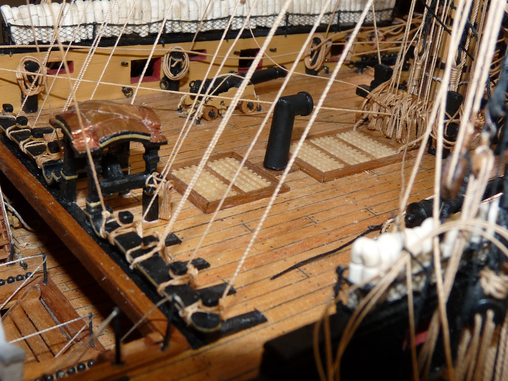
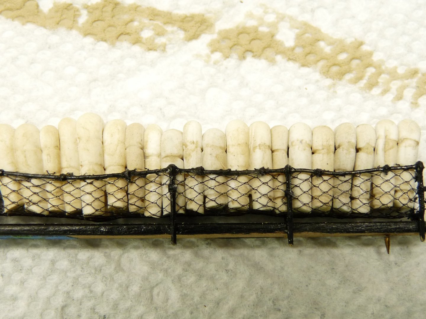
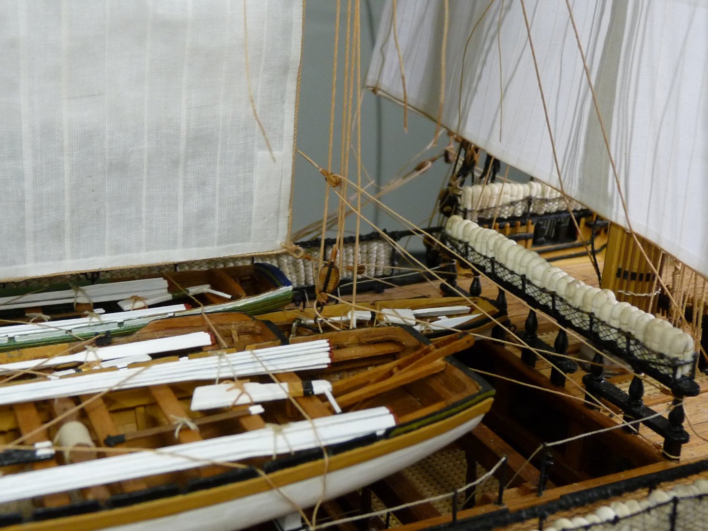
That's a hammock crane. full of rolled-up sailors' hammocks. They give protection against flying splinters and musket balls during an engagement with the enemy.
-
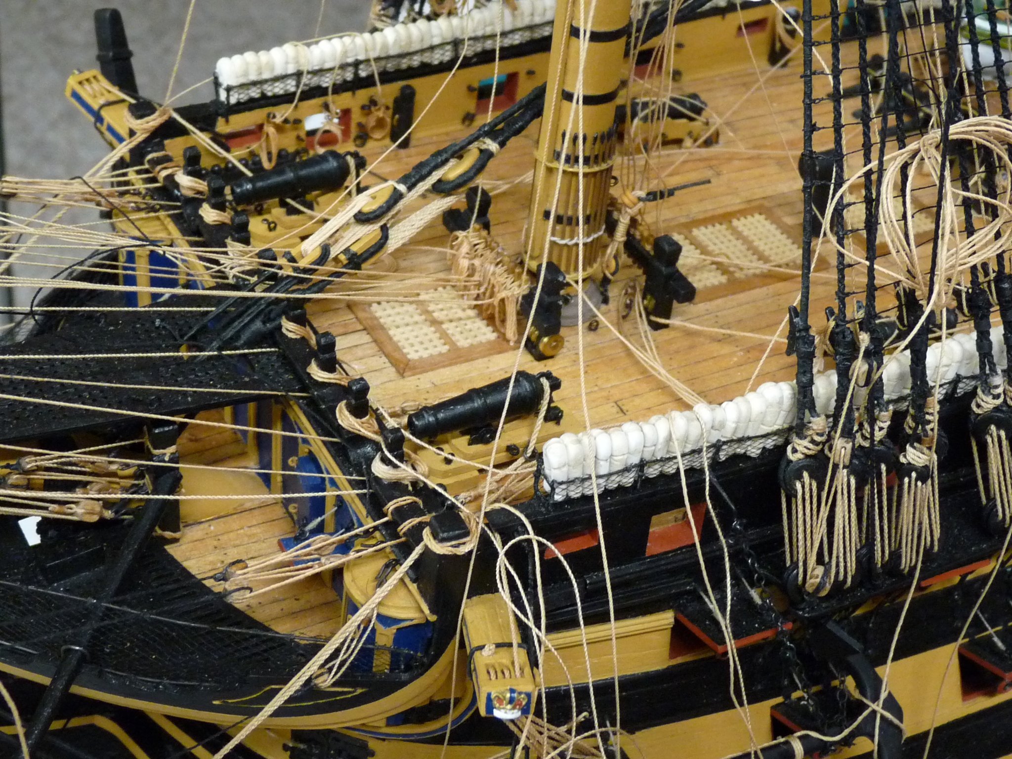
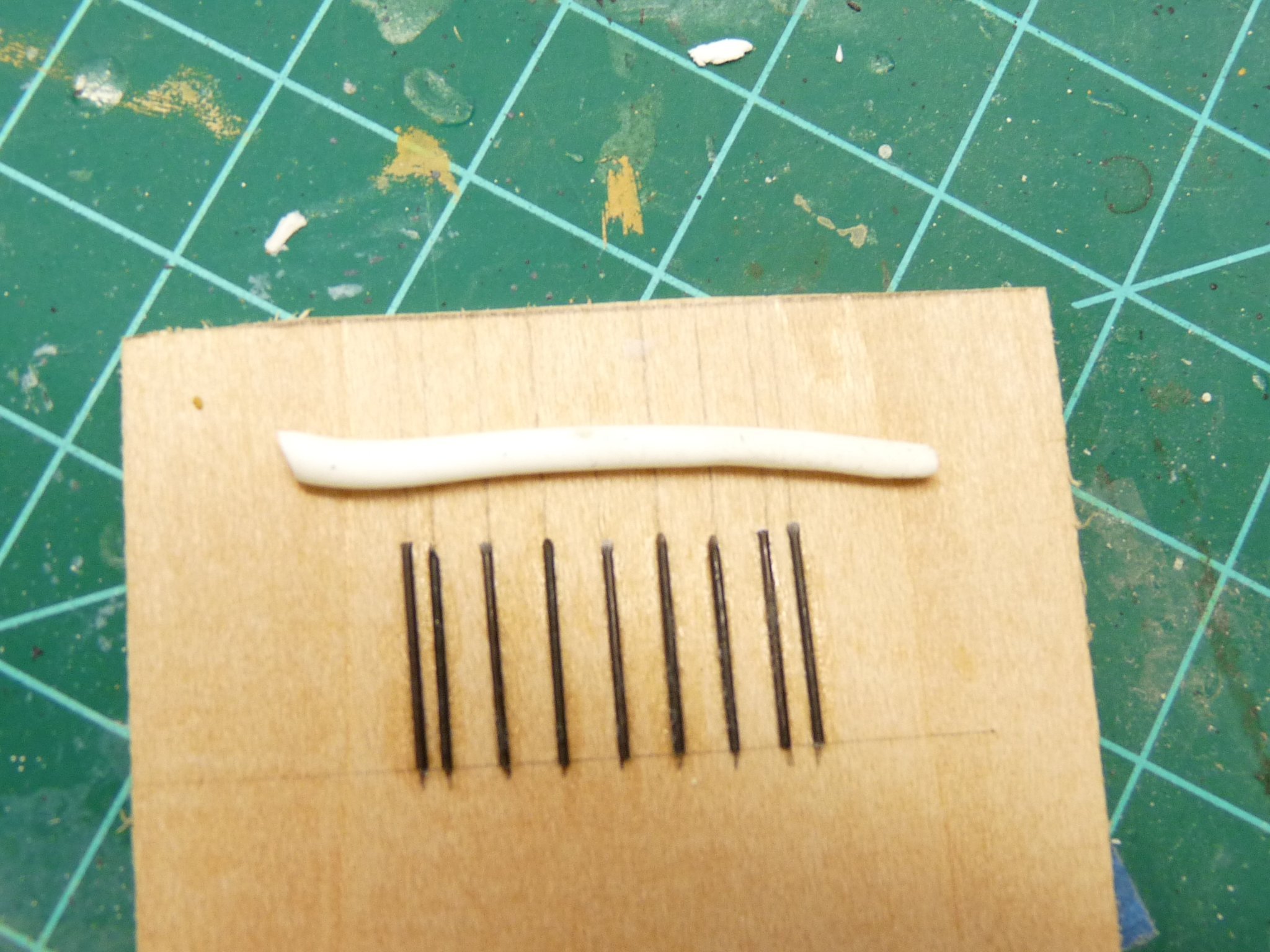
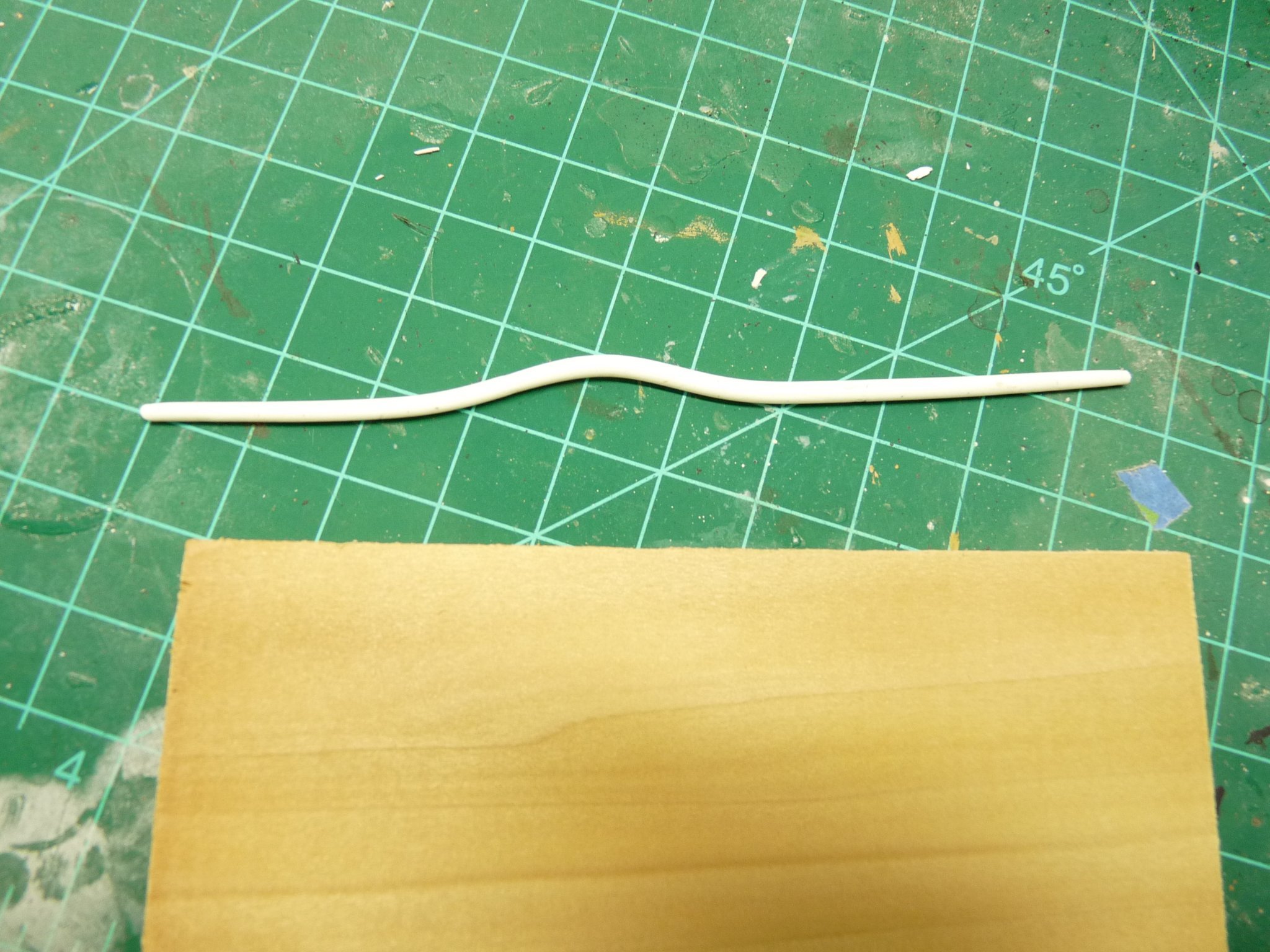
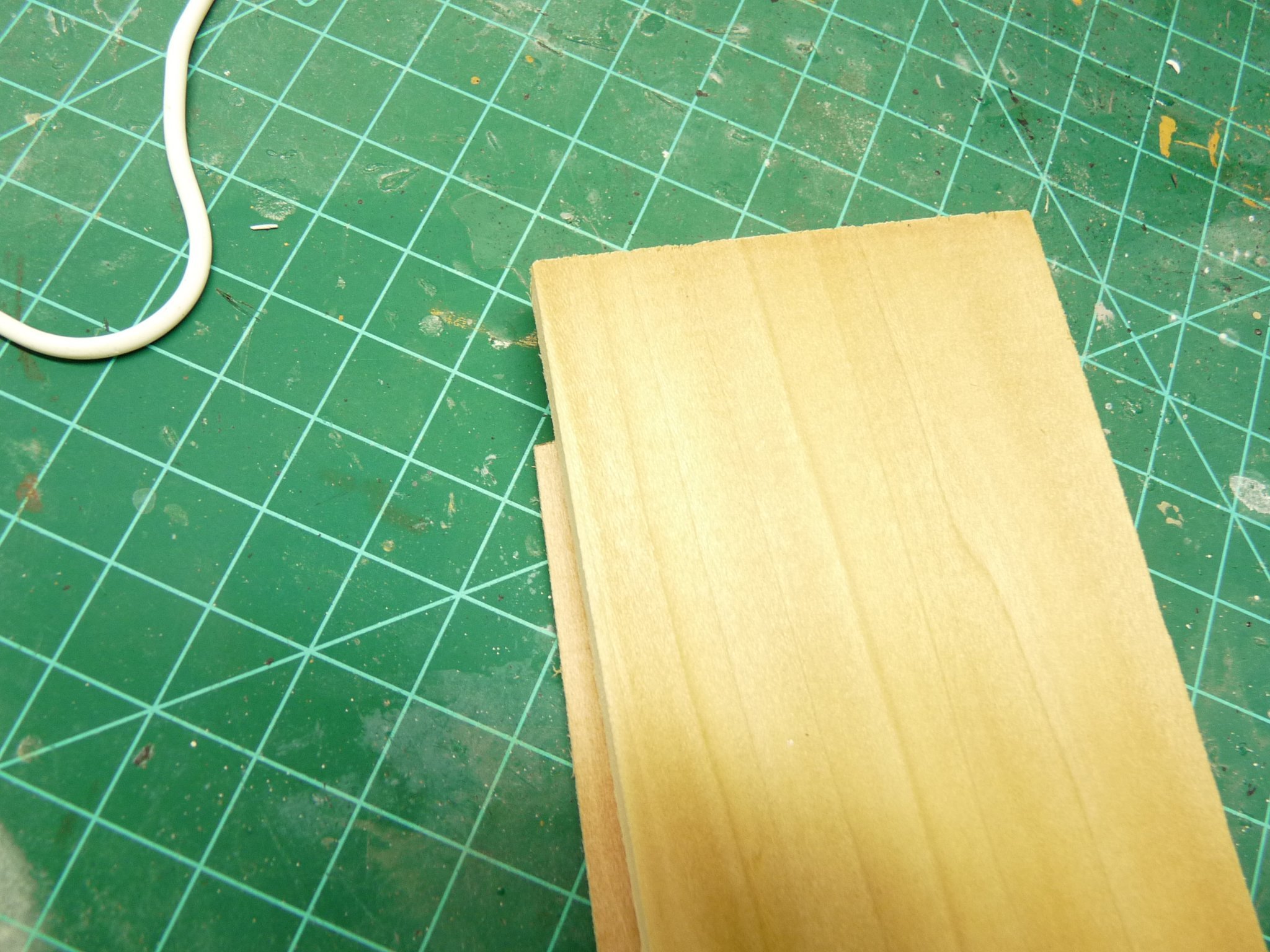
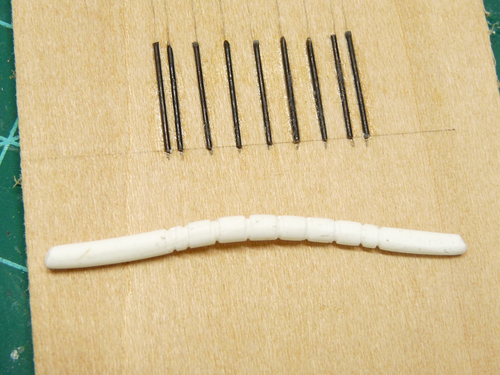
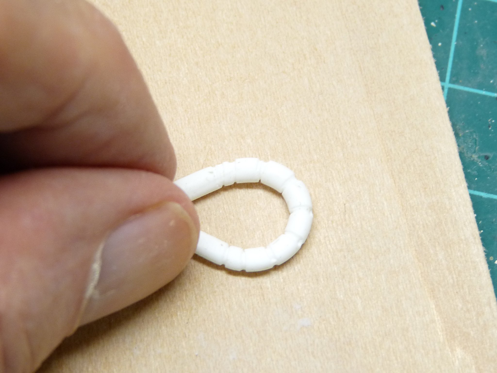
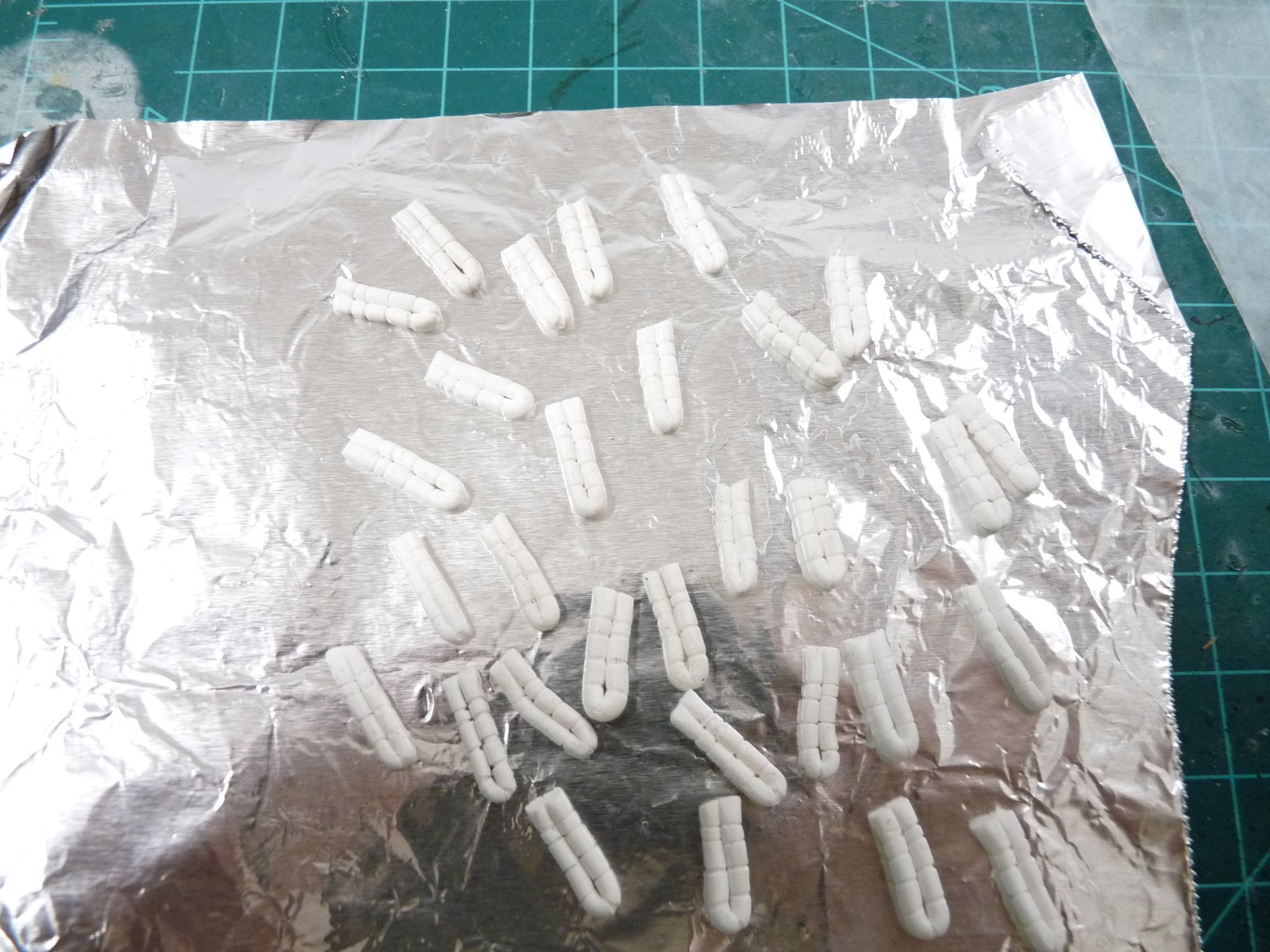
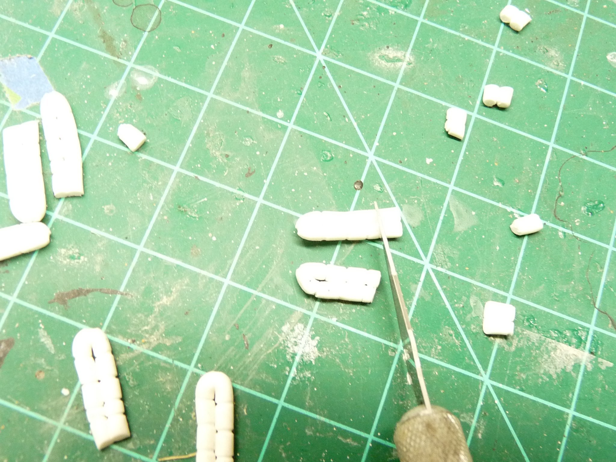
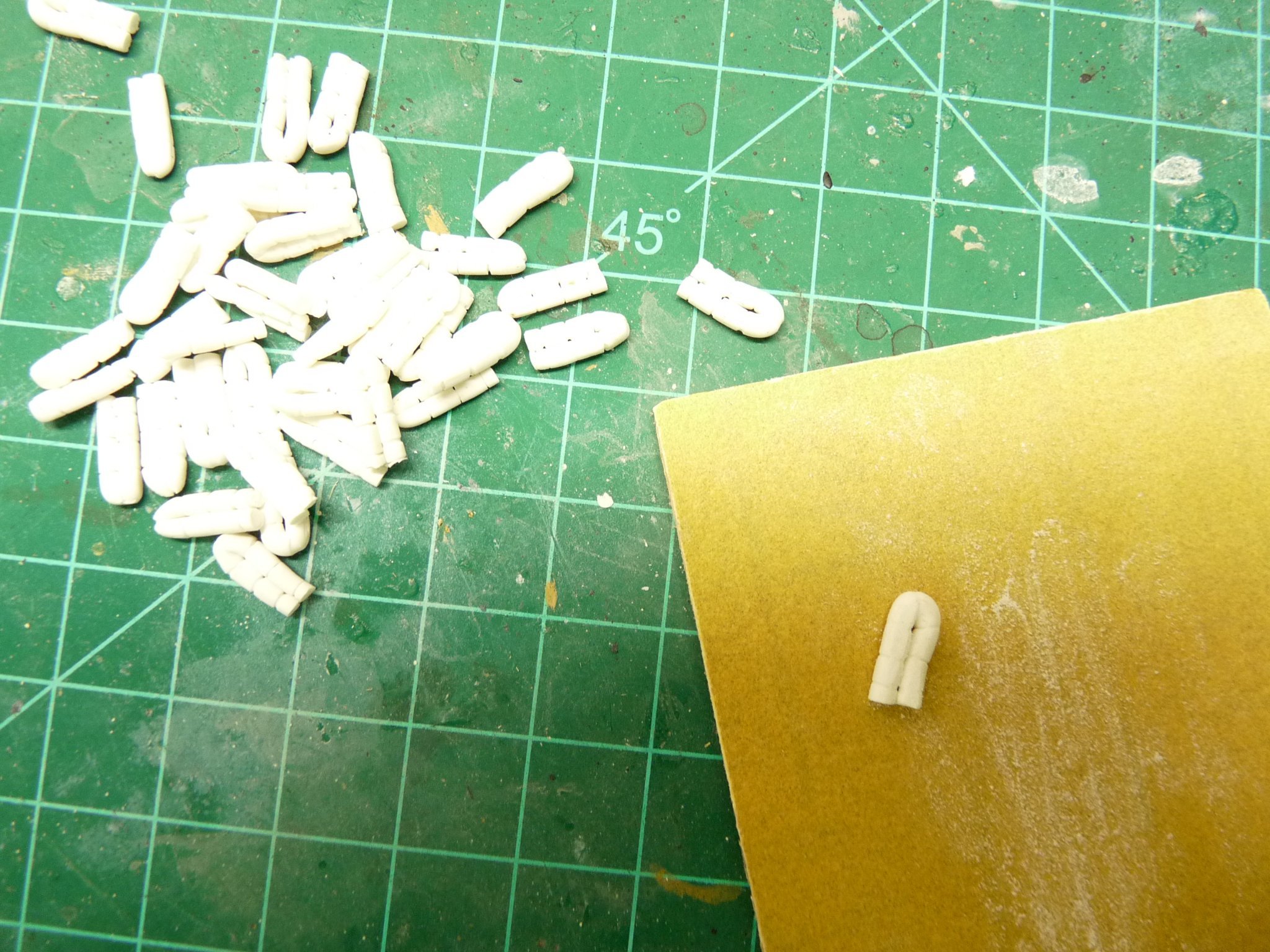
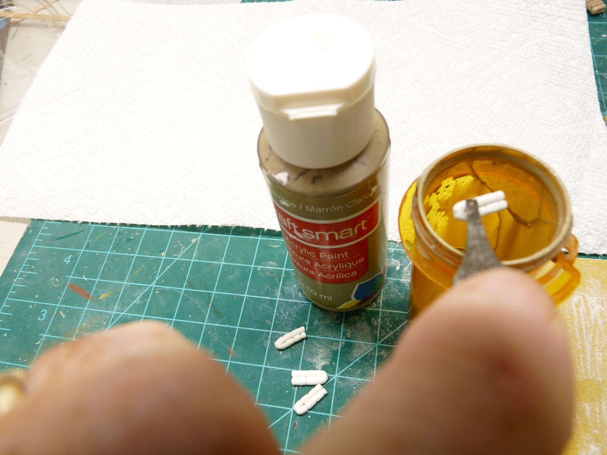
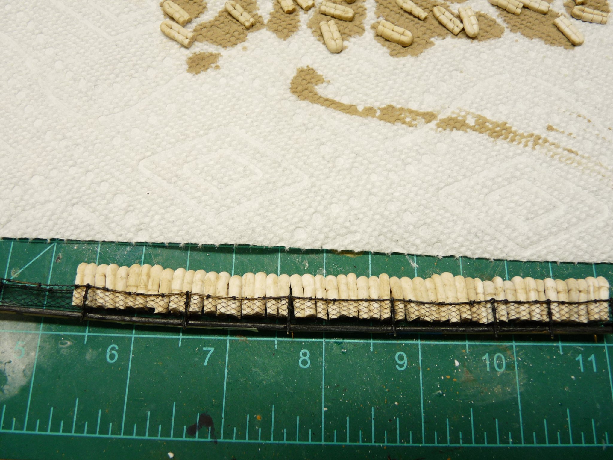
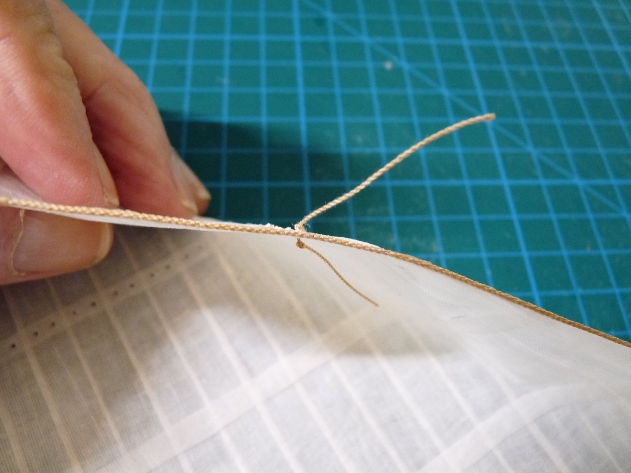
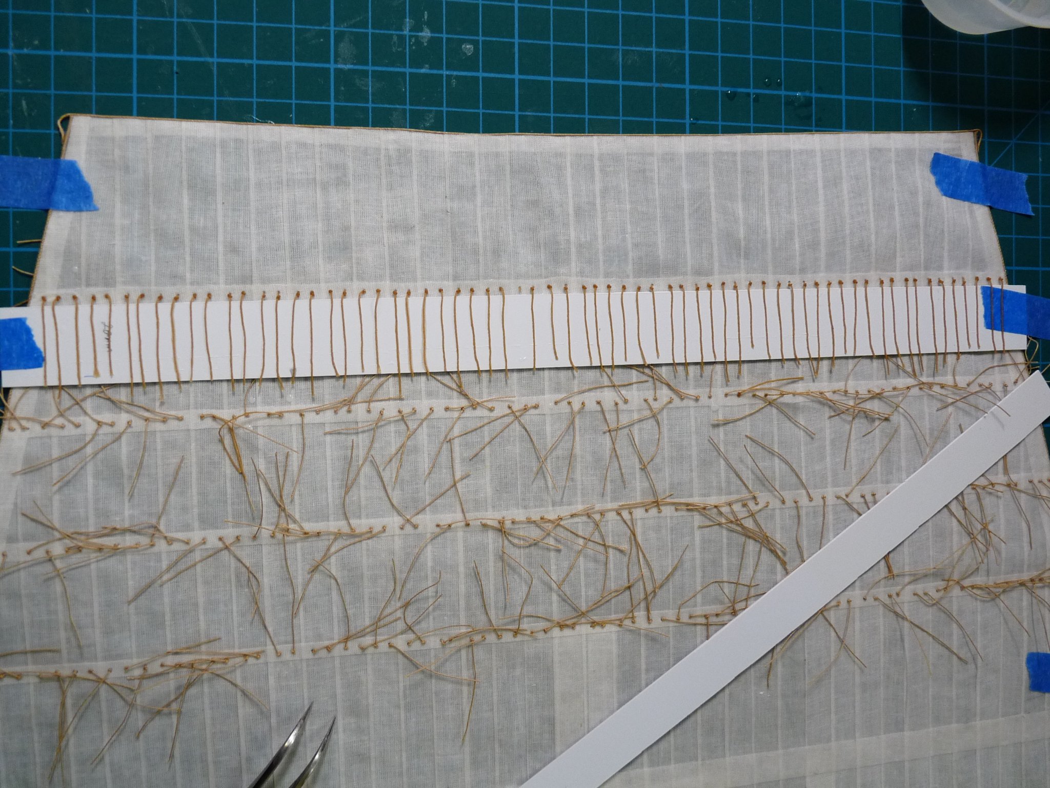
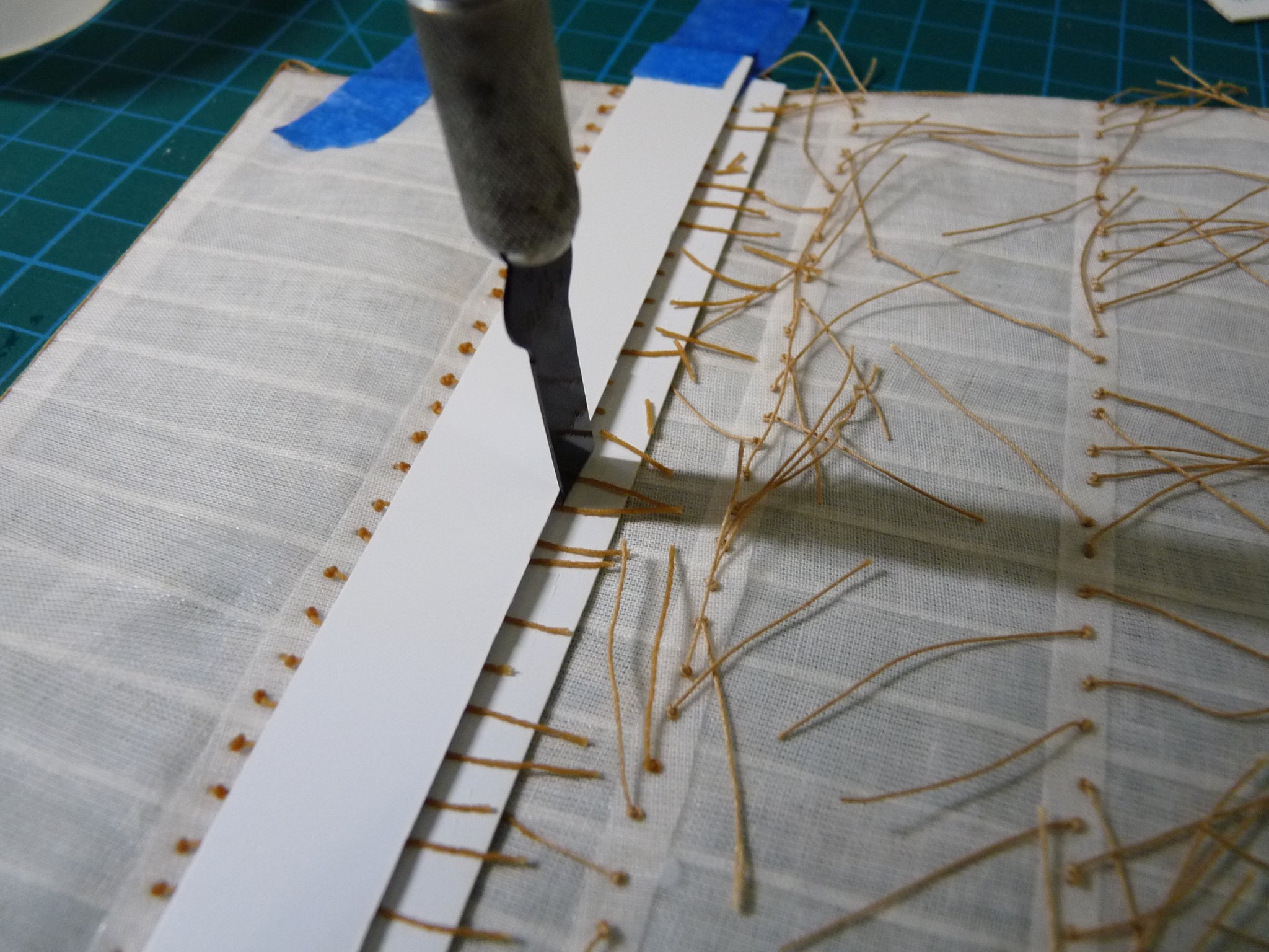
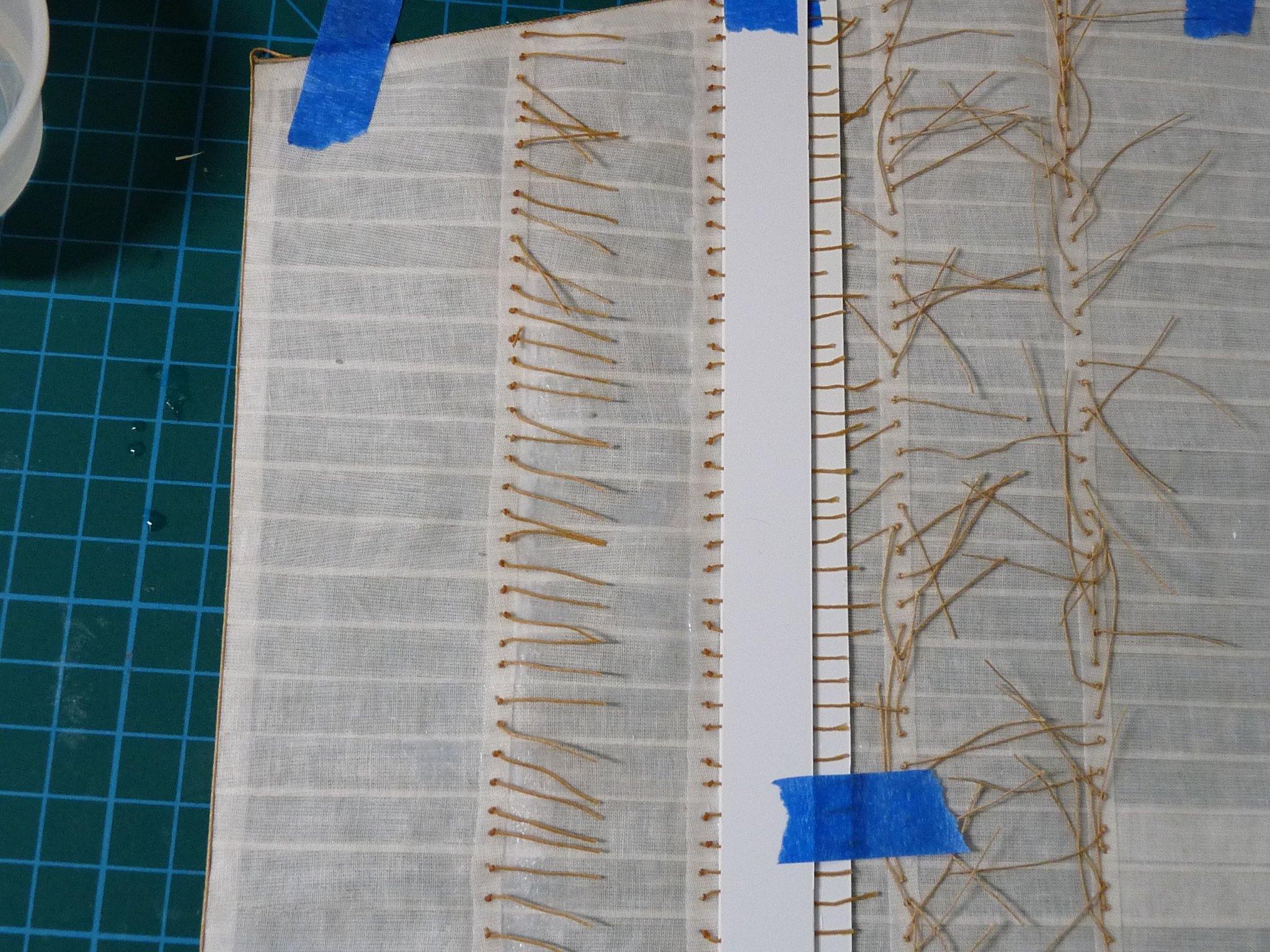
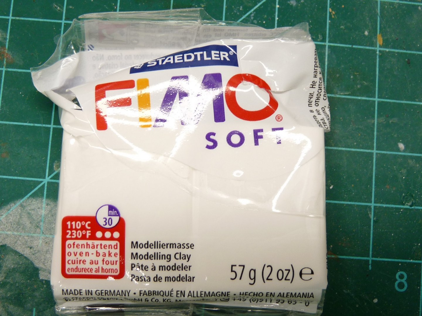
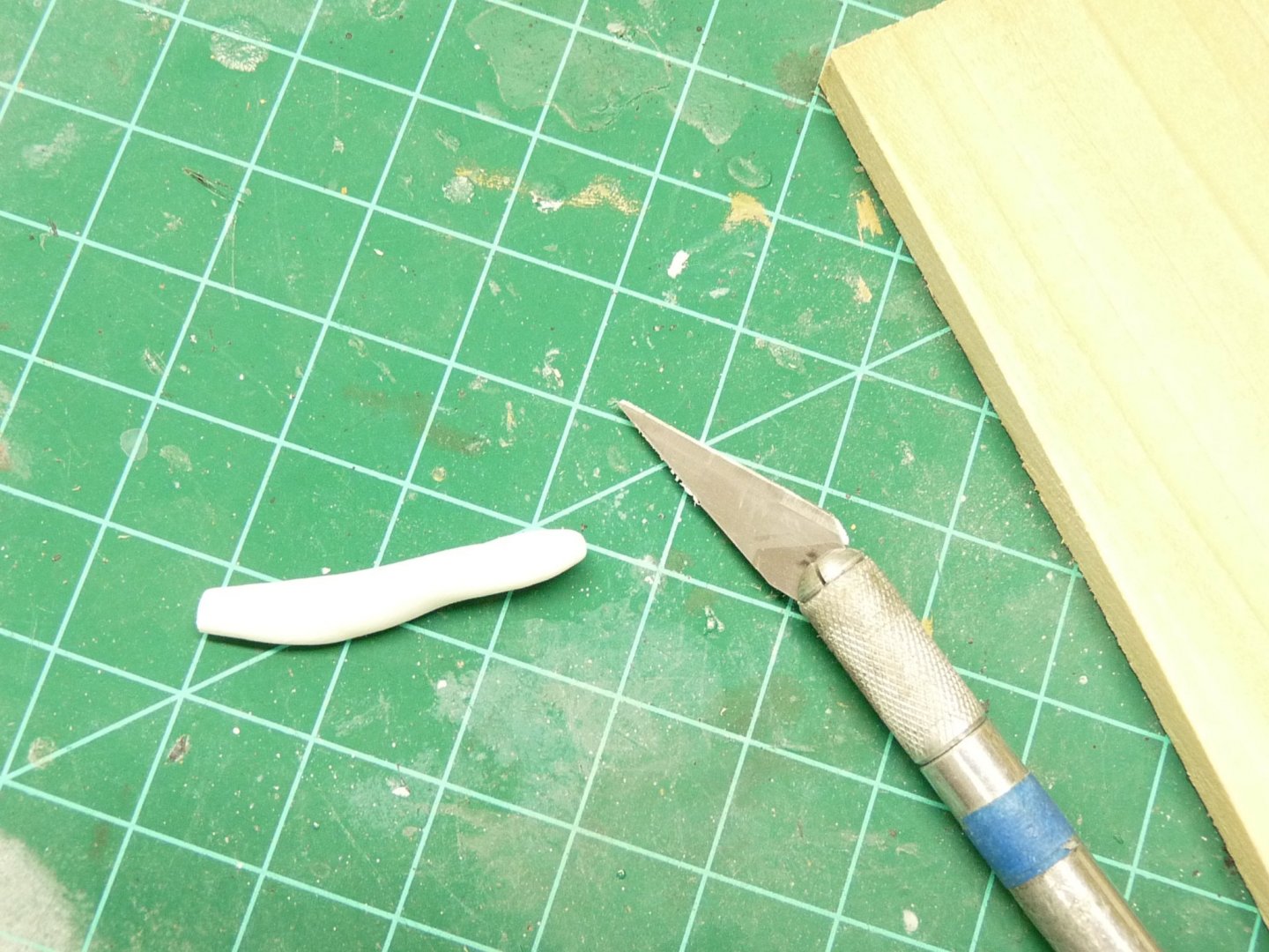
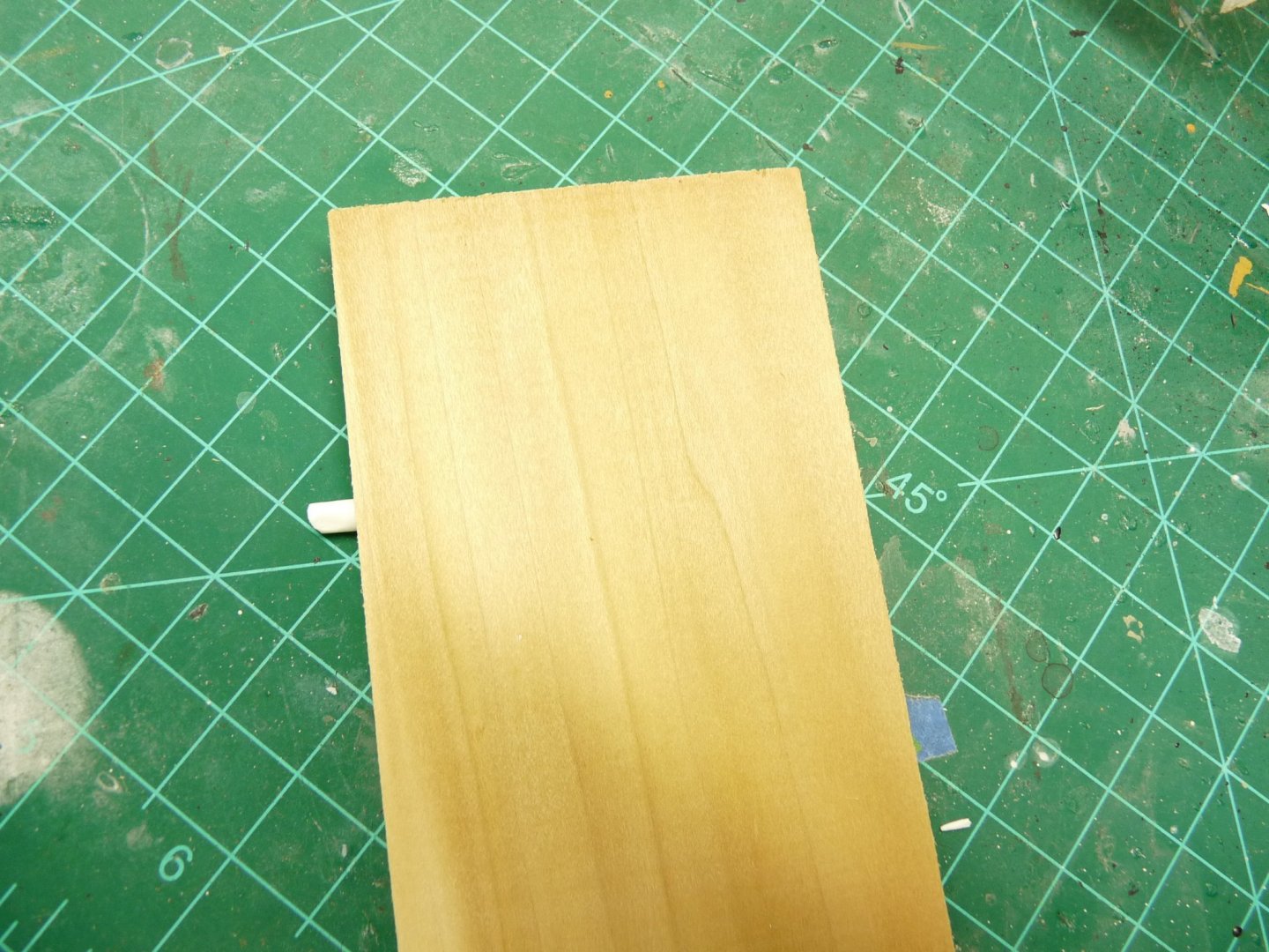
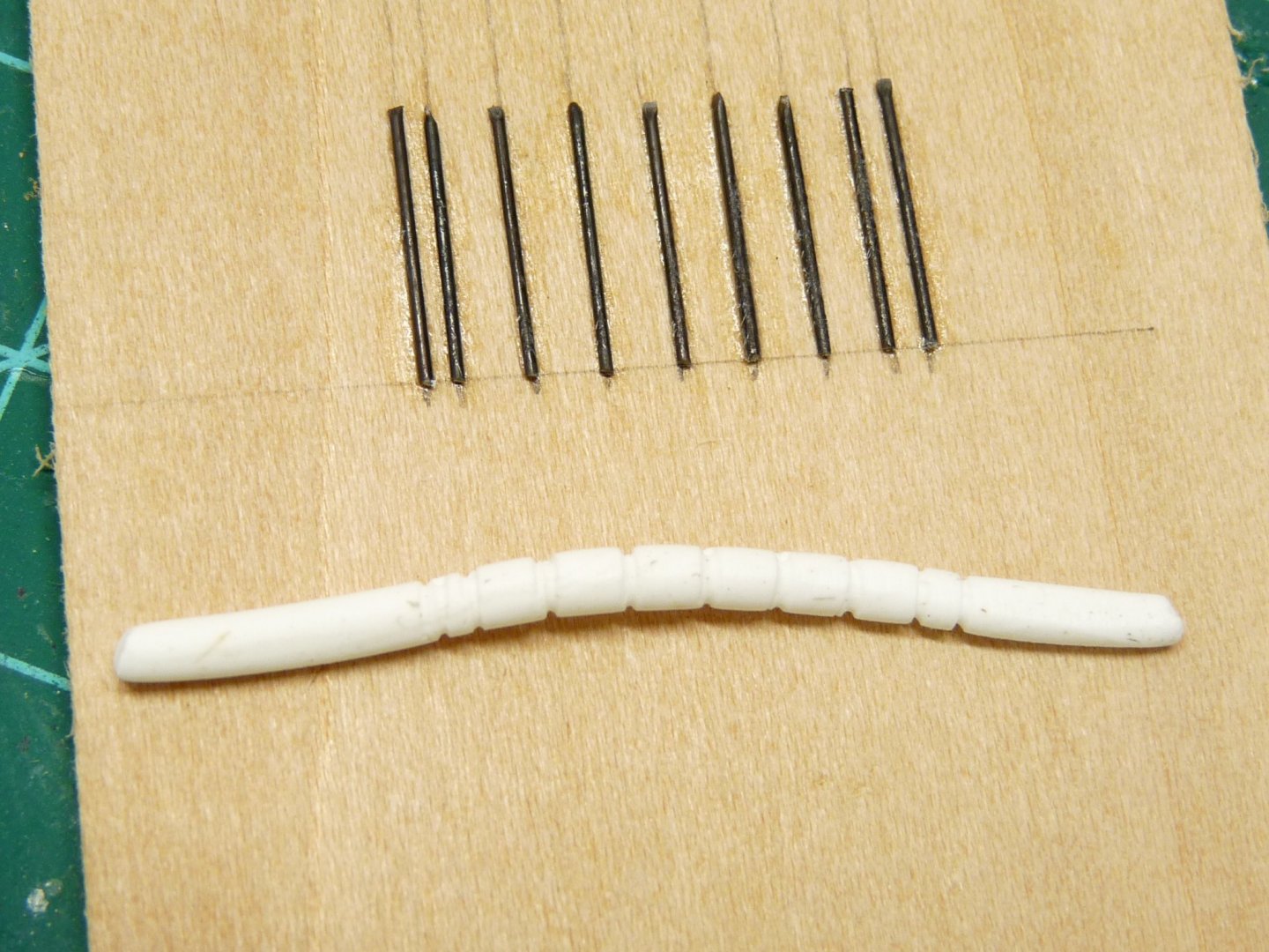
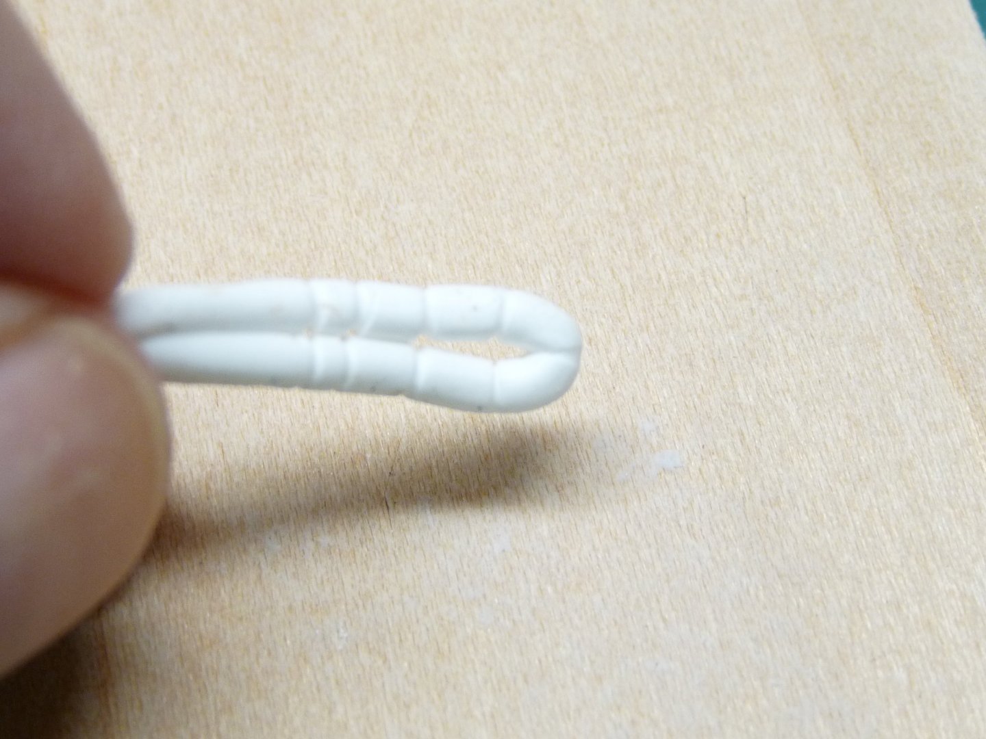
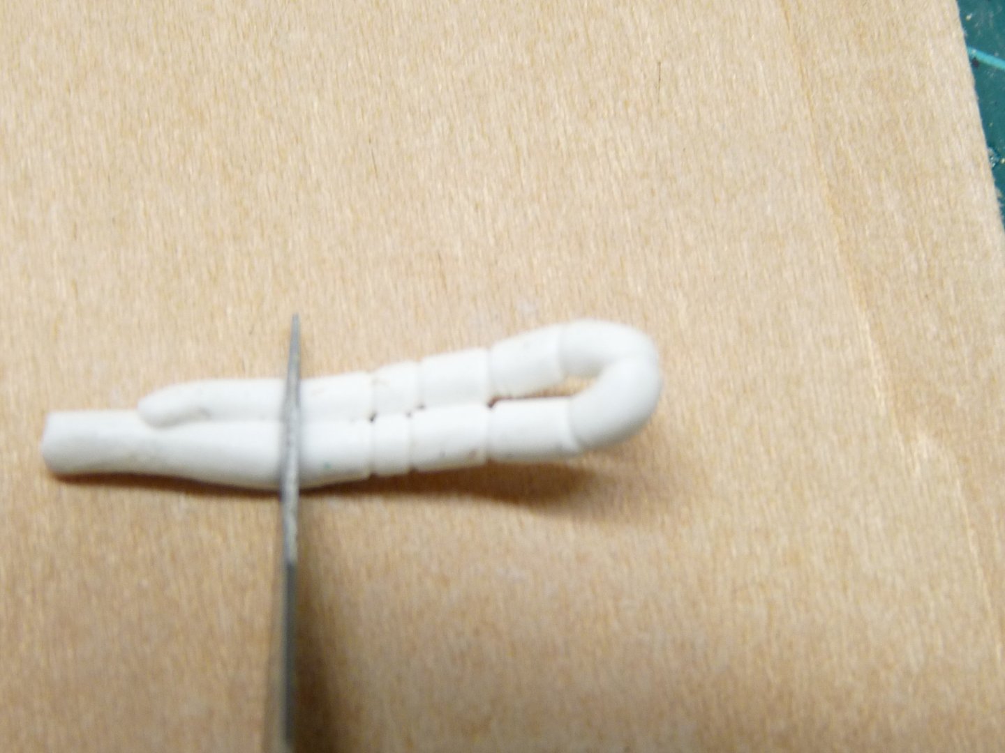
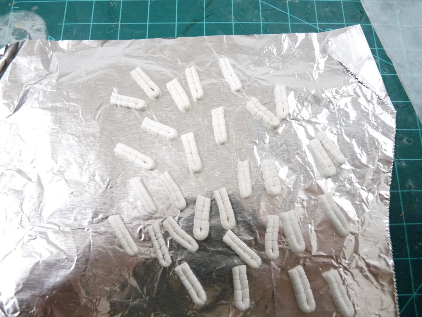
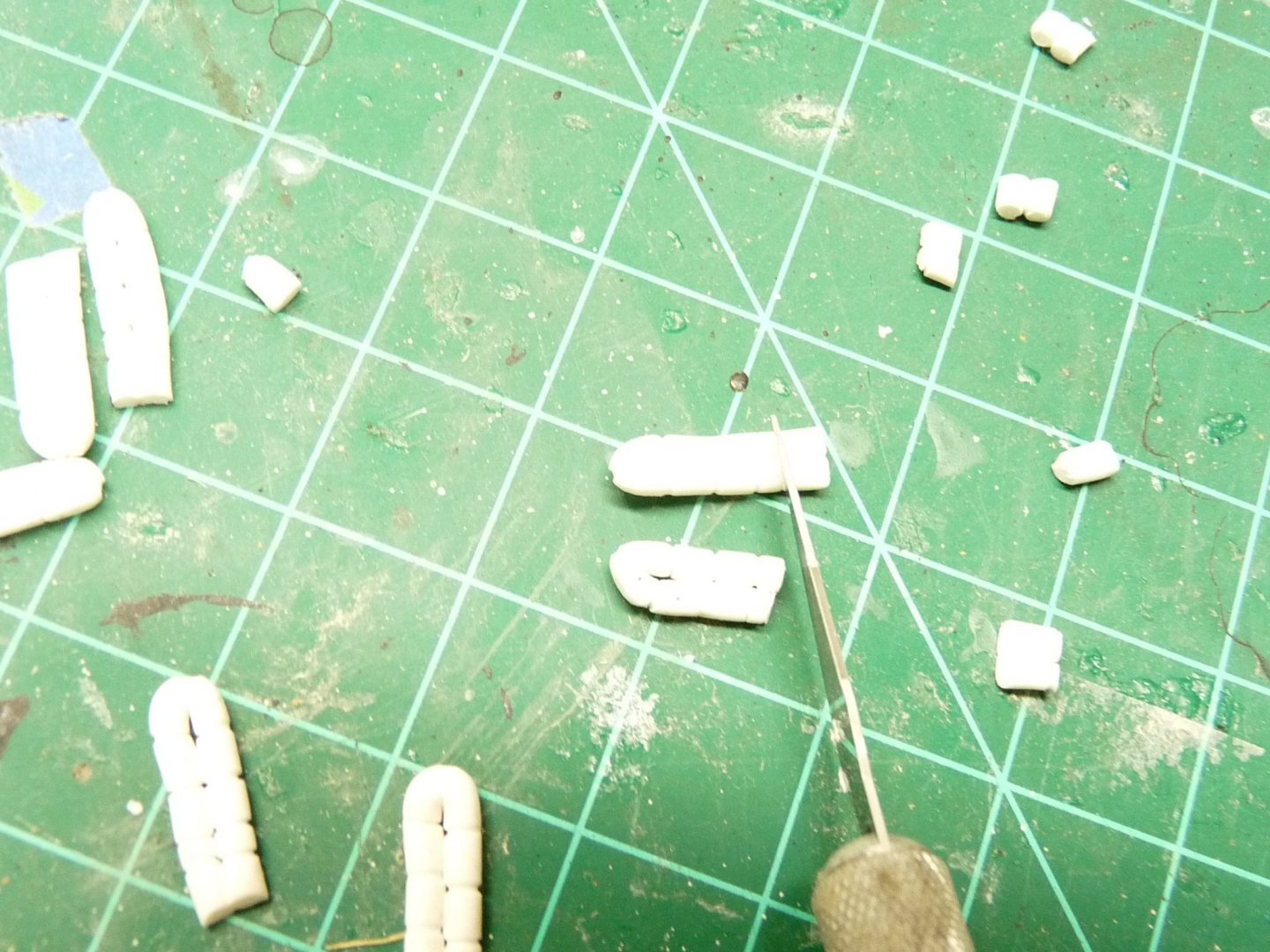
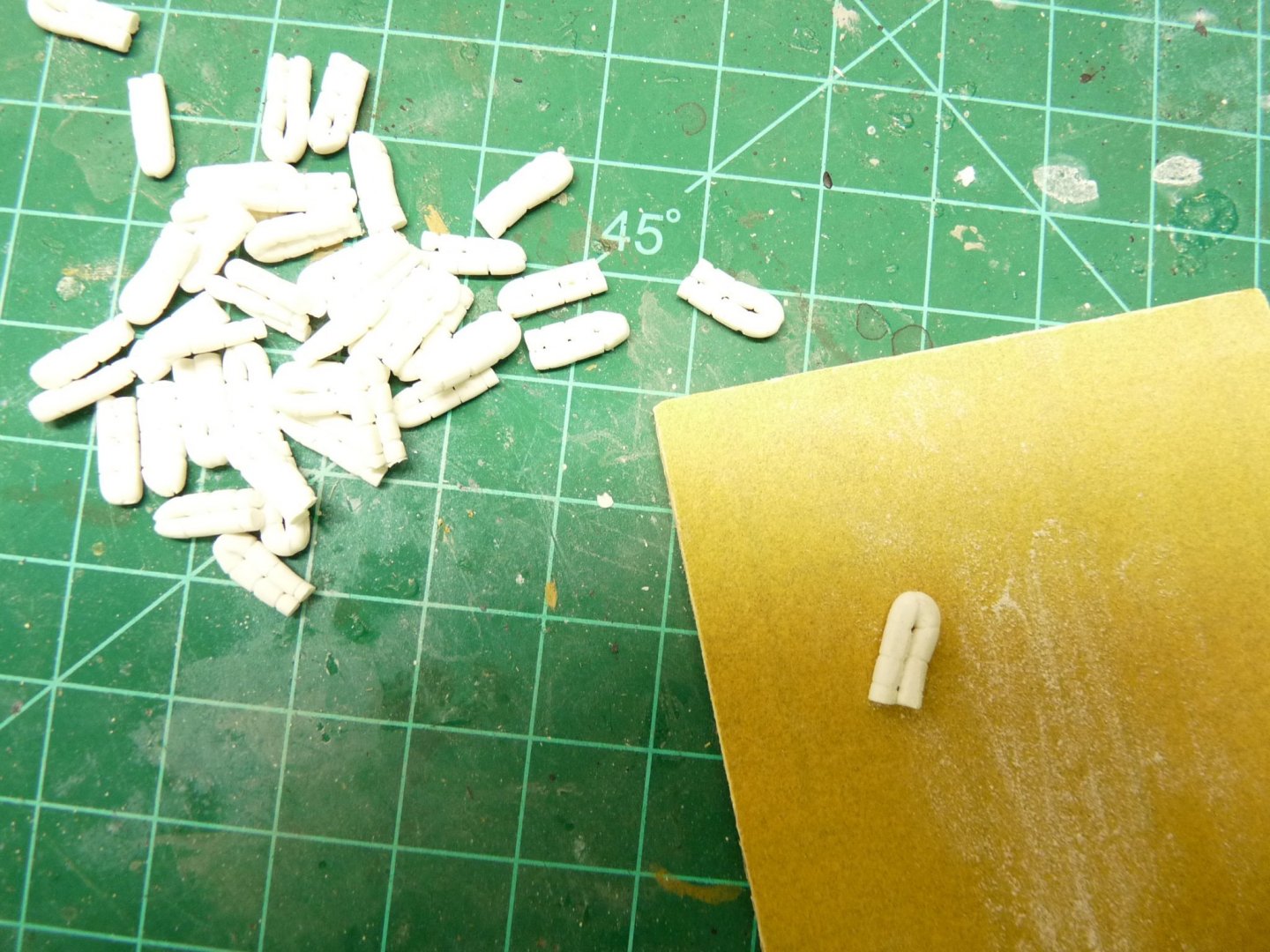
As I went along with my Victory build, I decided that I wanted to display her as she went into battle, including with her hammock cranes full. It was common practice, especially in times of war, for His Majesty’s ships to wake all hands an hour before dawn to prepare for a battle with any enemy ship that may appear nearby at dawn’s break. Hammocks were broken down, rolled and triced up, with the sailors’ bedding and other belongings inside the roll. The hammock tricing, as per the bosun, was with the regulated 7 circumferential turns of small stuff. The roll was then folded in half and stowed in a hammock crane at the sailor’s assigned position under the watchful eyes of one of the bosun’s mates. The reason for doing this was twofold; one to get them out of the way as there was little storage space below decks for personal belongings, and secondly to act as some degree of protection from the wood splinters that were the result of an incoming cannonball’s impact, and also from musket shot from the enemy’s Marines stationed in their fighting tops. The filled hammock cranes were also an impediment to boarding parties coming over the side. The weather deck of a line-of-battle ship during an engagement was not a nice place to be! The filled cranes were usually covered with tarps to protect them from the weather, but I decided to display them without covers so the individual hammocks could be visible. Hammocks were also lashed to the aft net barriers on the fighting tops to afford the Marines positioned there some protection from enemy musket fire. Victory had a complement of about 850 men, so making individual hammocks of this volume was going to be a challenge. My Vic is the Caldercraft 1:72 version, so the slightly over 6 foot long hammocks are about 1-1/4” in finished length. My aim was to make them showing the tricing lines, with the fabric a slightly off-white from the natural canvas color, as they would often get a little grimy and gray with use even though they were scrubbed regularly. I didn’t want the tricing to appear too stark, as that would detract from the random look that would have appeared as the hammocks were placed in the cranes. This meant no pure white canvas material, and no dark contrasting lines to simulate the tricing lashings. I tried several types of material, including cloth and paper of all sorts, but none seemed to look right to me or were just too difficult to make in large numbers. I then tried some polymer modelling clay called Fimo, which showed some promise. Fimo can be manipulated like regular modelling clay, but after taking the desired shape can be oven-baked for several minutes to produce a hard, stable object. As I experimented with the Fimo, I developed a procedure and a simple jig that produced acceptable (to me) hammocks – generally the same, but different enough from each other to present some degree of randomness in their rolling and placement. Fimo comes in a couple of different consistencies, and a limited palette of colors – none of which was exactly what I wanted for the hammocks. I thought about combining two or more colors of the Fimo into a composite color that approached what I wanted for the finished hammocks, but was afraid that I wouldn’t be able to duplicate it over and over as I needed more material. In the end I decided on the “soft” version of the Fimo in White – I would color them later to the desired hue. To simulate the tricing grooves, I glued seven .020” soft iron wires about an inch long at equal distances apart over 1” on a scrap piece of 2” wide, ¼” thick scrap of basswood. 2 more wires were added about 1/8” outside of the first and last tricing lines – these would serve as the guidepoints to trim the finished hammocks to their proper lengths. First a chunk of Fimo was torn off the block, about the size of a grape. It was softened slightly by rolling and warming in the fingers into a rough cylinder. This was then rolled between two wooden planks about 3” wide to get a long cylinder about .100” in diameter and 4” or 5” long. The length is not important, and you will soon be able to “eyeball” the proper diameter close enough - some diameter variation is to be desired to simulate randomness. Cut off a chunk of the roll about 1-1/2” to 2” long, place it near the wire strips, and using another flat board press down and roll the Fimo between the boards once to leave the tricing line impressions from the wires on the hammock. Rolling more than once will blur the lines. If it’s not right, just wad it up again and repeat. I would usually make them up in batches of about 50 to ease the tedium. Once the tricing lines have been impressed, carefully fold the hammocks in half, bringing the two outer impressions (the cut-off lines) together. This will leave a shape like a Greek Omega, with a bulge at the top. Don’t try to fix this with your fingers, but squeeze the roll together gently between two small chunks of flat wood to make the sides parallel, or they won’t fit right in the hammock cranes. At this point I trimmed them a little longer than the cut-off lines, prior to baking them. I probably could have trimmed them to the exact length here, but this became my routine. Now they get placed on a piece of aluminum foil and baked in the oven at 230° F for 30 minutes to harden them. After they have cooled, trim to the proper length. Now rub the sides on a piece of medium sandpaper, which will make them flat so that they lie properly next to each other in the netting. Keep a couple of them rounded on one side to use at the ends of the arrays in the netting. I wanted the finished hammocks to appear a slight grey-tan, so I made up a diluted (abut 60-40 water to paint) batch of acrylic paint in the desired shade in a pill bottle, and soaked the baked batch of hammocks for a few minutes. Then they were placed on a piece of paper towel and blotted to get most of the paint off the surface, which left the paint darker in the tricing line grooves. The hammocks were then glued side-by-side in their nettings. I did this in batches of about 5-8 pieces at a time, letting the glue set before adding more hammocks to avoid getting them out of alignment. Foe ease of manipulation, this was all done prior to mounting the hammock crane/cap rail assembly in place on the hull.


-
Thanks to Kevin, Ian and Mort for the nice comments. Sorry it's taken so long to respond, but I was busy with company over the Father's Day weekend, and this is the first opportunity I've had to get to the computer. I've had some questions and comments about the sails and hammocks; I think maybe I'll post a couple of practicums on how I made them - not that they are the best examples, but that my procedures may be new to some folks who can probably improve on them. This may not be the best place to post them, as they may not be seen by many of our members, but at least the info will be out there.
-
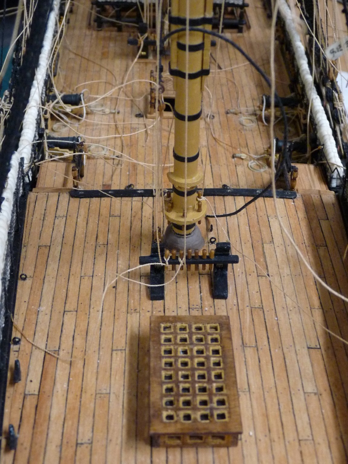
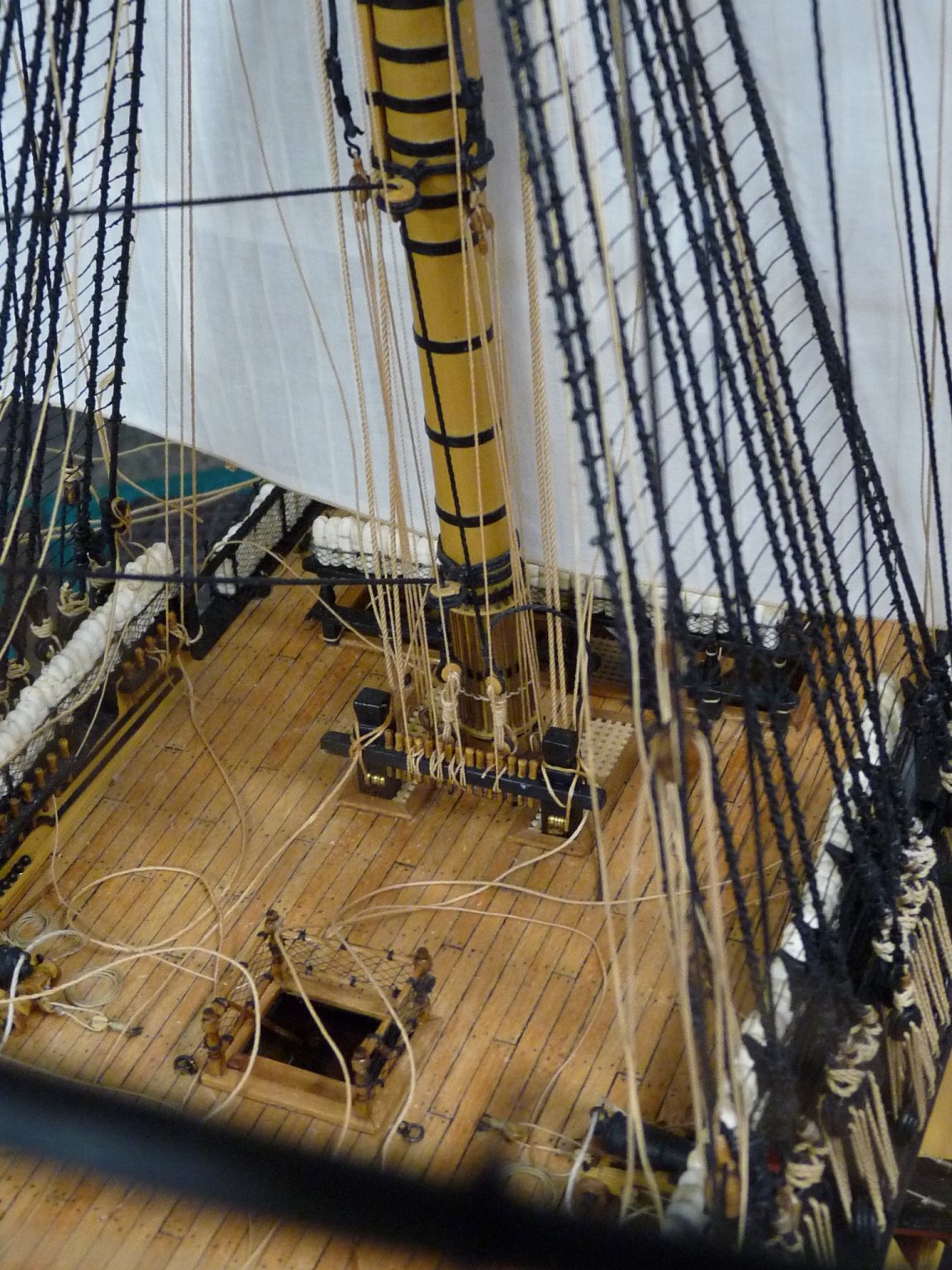
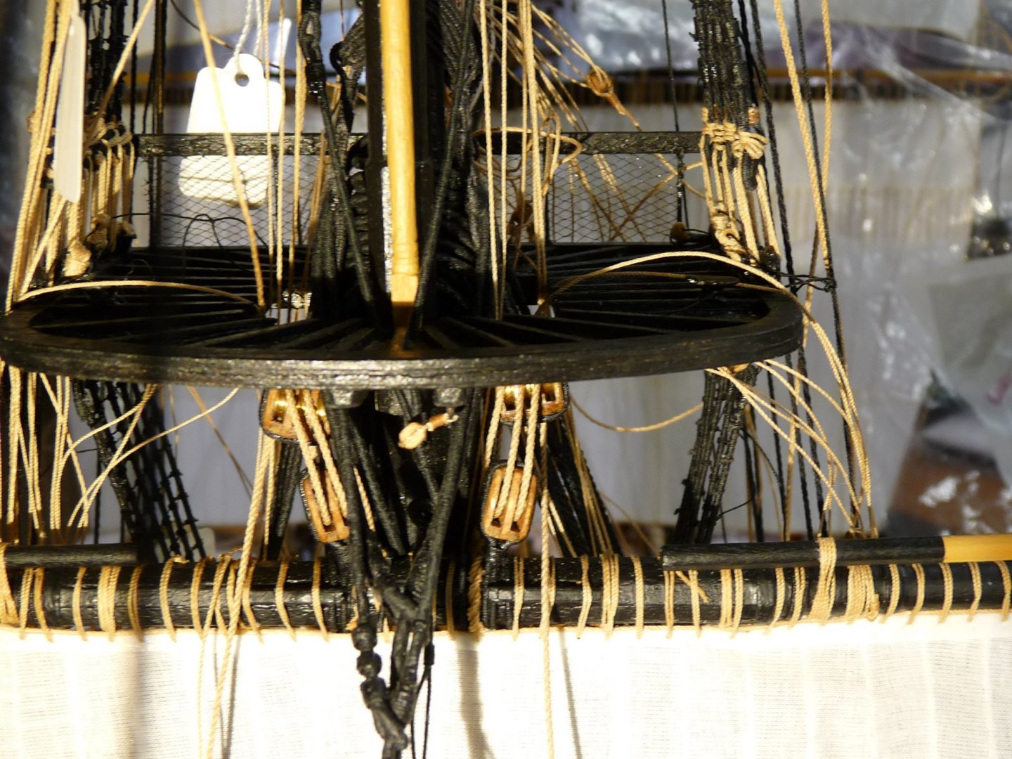
Adding the main topyard/sail. Tyes being rigged.
-
I have now shipped and rigged the two lower main stay sails (the main stay sail- the lower one, and the main topmast stay sail- the upper of the two). There will ultimately be two more above these - the middle stay sail and the main topgallant stay sail. These will have to wait until later, when I install the topgallant masts and their respective stays. Next up will be the main top yard/sail assembly. already made and awaiting placement.


-
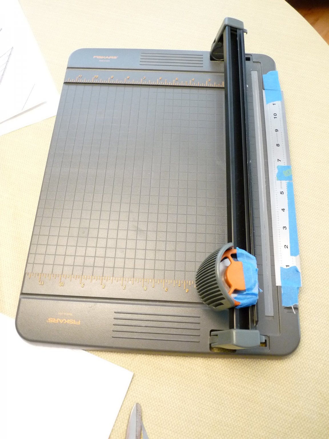
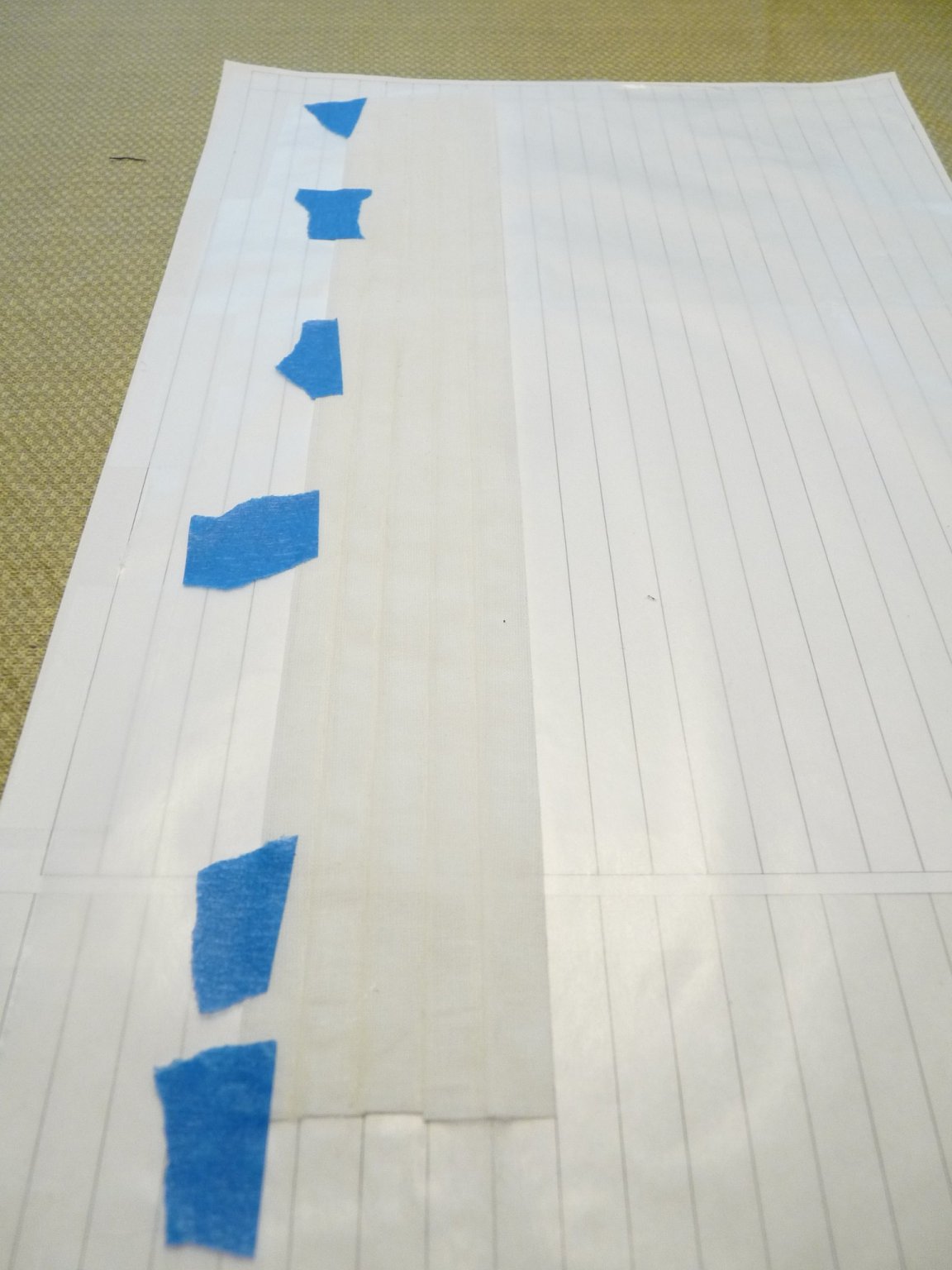
Stitching sails with sewing machine
tedrobinson2000 replied to Jorge Hedges's topic in Masting, rigging and sails
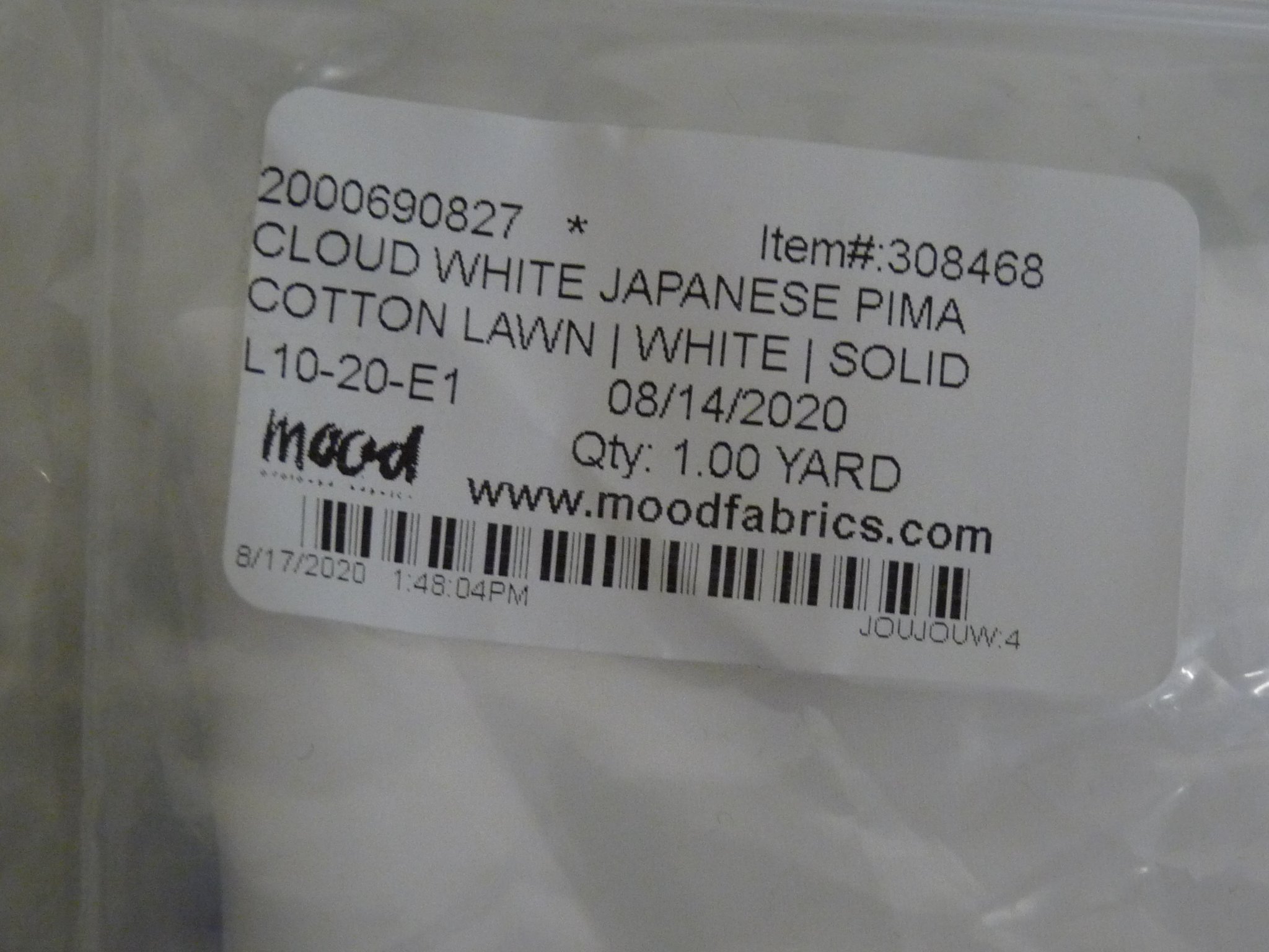
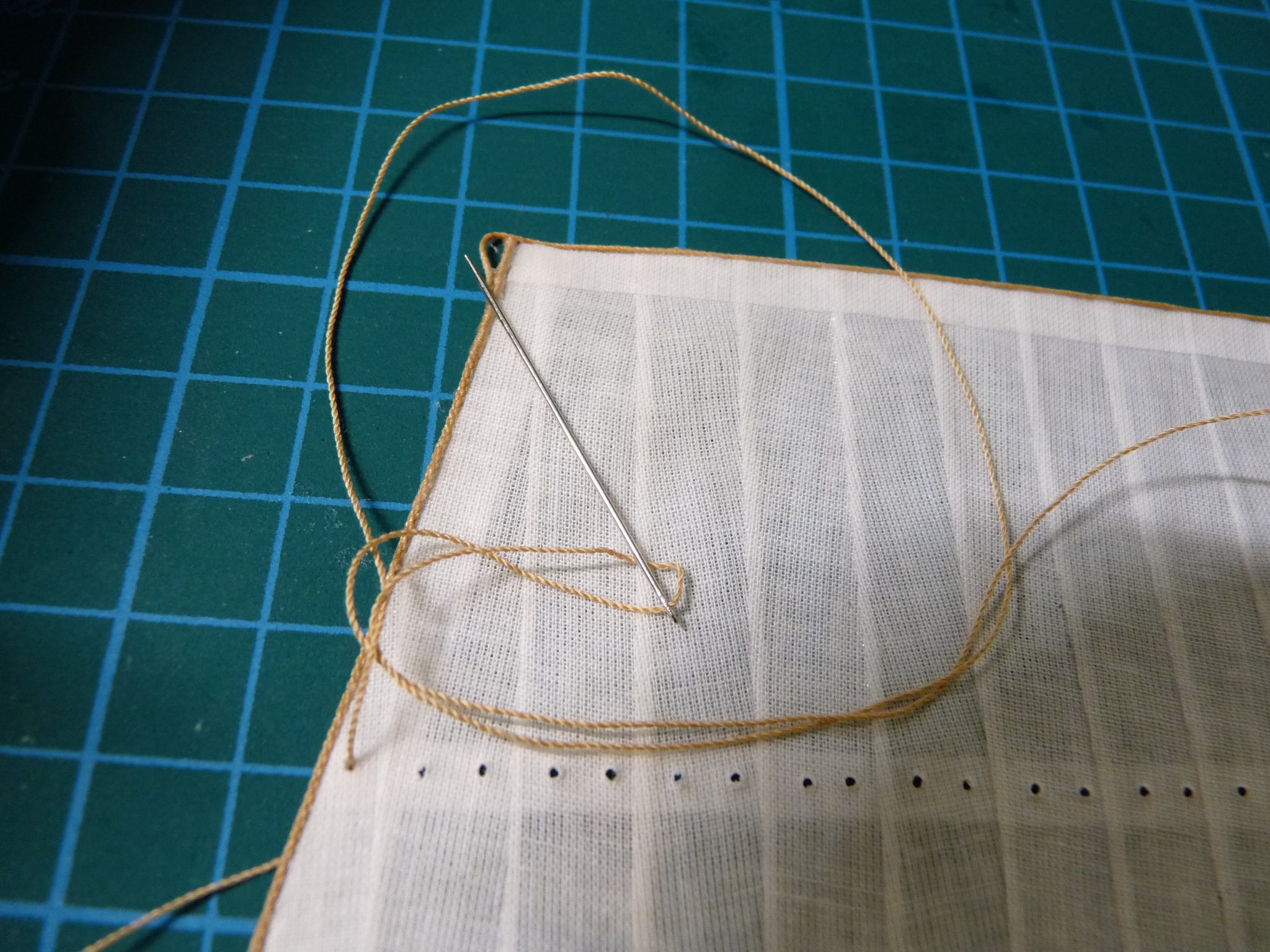
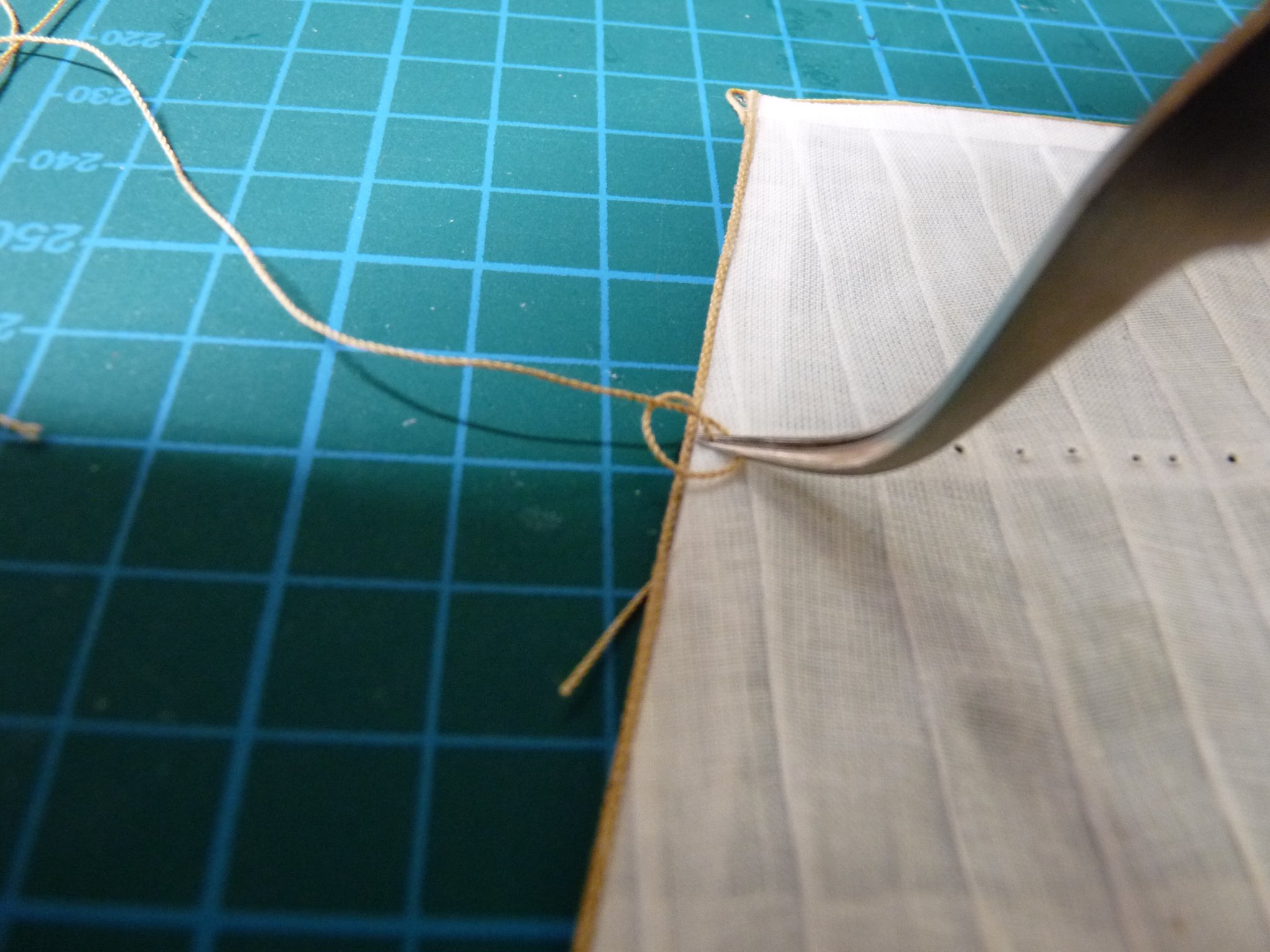
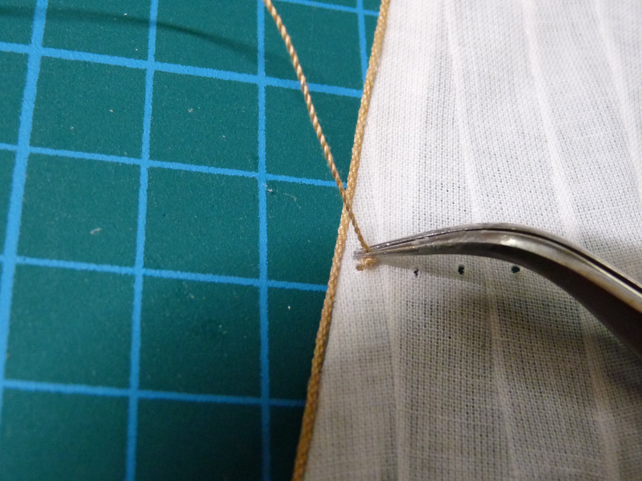
Hi Allan, I got the lawn cloth on eBay from mood fabrics. I got some white at first, but it was too starkly white, so I got some off-white ivory instead. I considered dying the white, but was afraid that as I got deeper into the sail making (Vic has 22 sails, excluding the stuns'ls) and needed more I wouldn't be able to match the tone. The ivory worked out well for me. I just checked Mood's website, and they don't list the ivory as being in stock, just 4 other colors. Other vendors may carry it, though. Don't know the exact thread count, but it is very soft and pretty sheer. Only $10/yd on eBay, maybe cheaper elsewhere. I made my own rope using Coats Quilt + thread (Camel color for running rigging, and black for standing rigging) and Chuck's Rope Rocket. The single Quilt+ thread mics at .009". I made many different sizes by varying the numbers of threads used, and during prototyping gave them alphabetical tags, which sort of stuck. A was a single thread of Quilt+, B was 2 threads twisted together (.013"), C was 3 threads (.018"), D was 4 threads (.021"), E was also 4 threads (.021") but consisted of 2 B ropes, etc. In this case the E rope looked better than the D rope so D was abandoned. The reef points on the picture of the sail that I uploaded (it was the fore topsail) were done with B rope - the smallest that I could get thru the eye of a small needle. Tie a knot and inch or more from the end, pull the needle through the reef band, then tie another knot up close to the sail and trim longer than needed. After they are all in for one reef band, I used two pieces of thin polystyrene sheet, one as a bucker and the other as a length template, to trim them to a uniform length. The bolt rope for this particular sail was my G rope, which is .025", - 3 B's twisted together.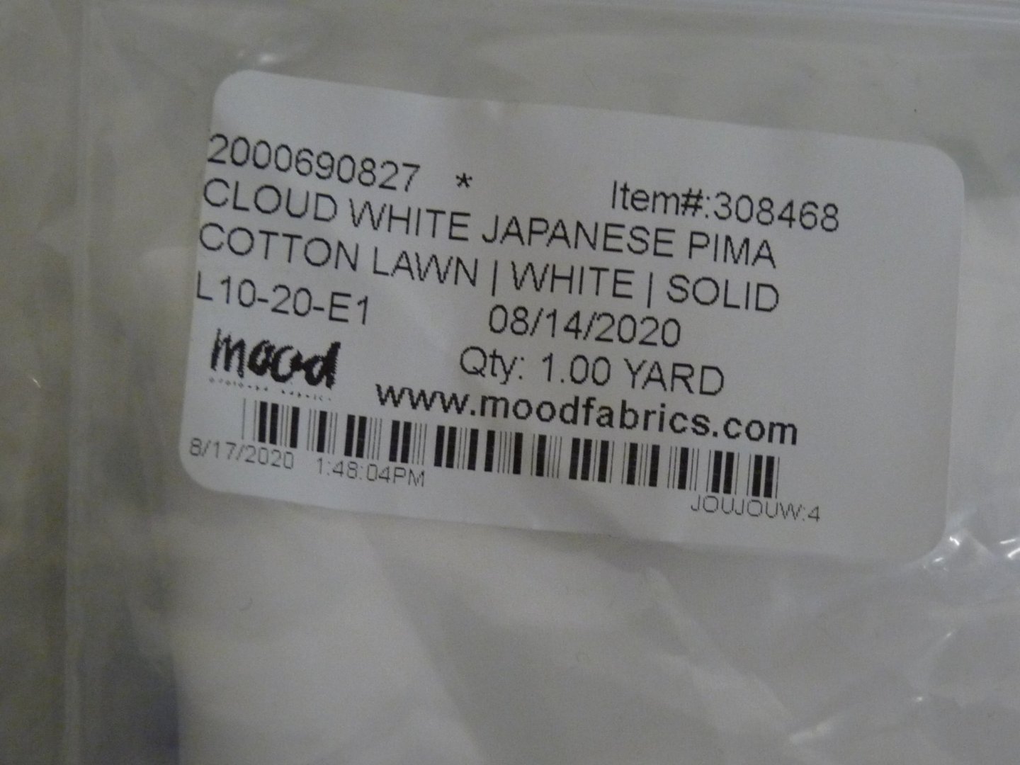


-
My guess is that the "minimum" length specified in historical contracts was the minimum lumber length that the shipyard would accept from the lumber supplier - not the minimum length that would be applied during the planking procedure. Note also that short lengths of planking are much harder to apply in area of extreme curvature, such as the bows. Seems to me that the shipwright would have lined the hull in such a way as to avoid shorter lengths in those areas. Doesn't mean that shorter lengths weren't necessary elsewhere.
-
Stitching sails with sewing machine
tedrobinson2000 replied to Jorge Hedges's topic in Masting, rigging and sails
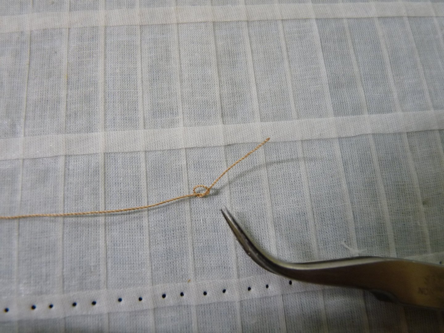
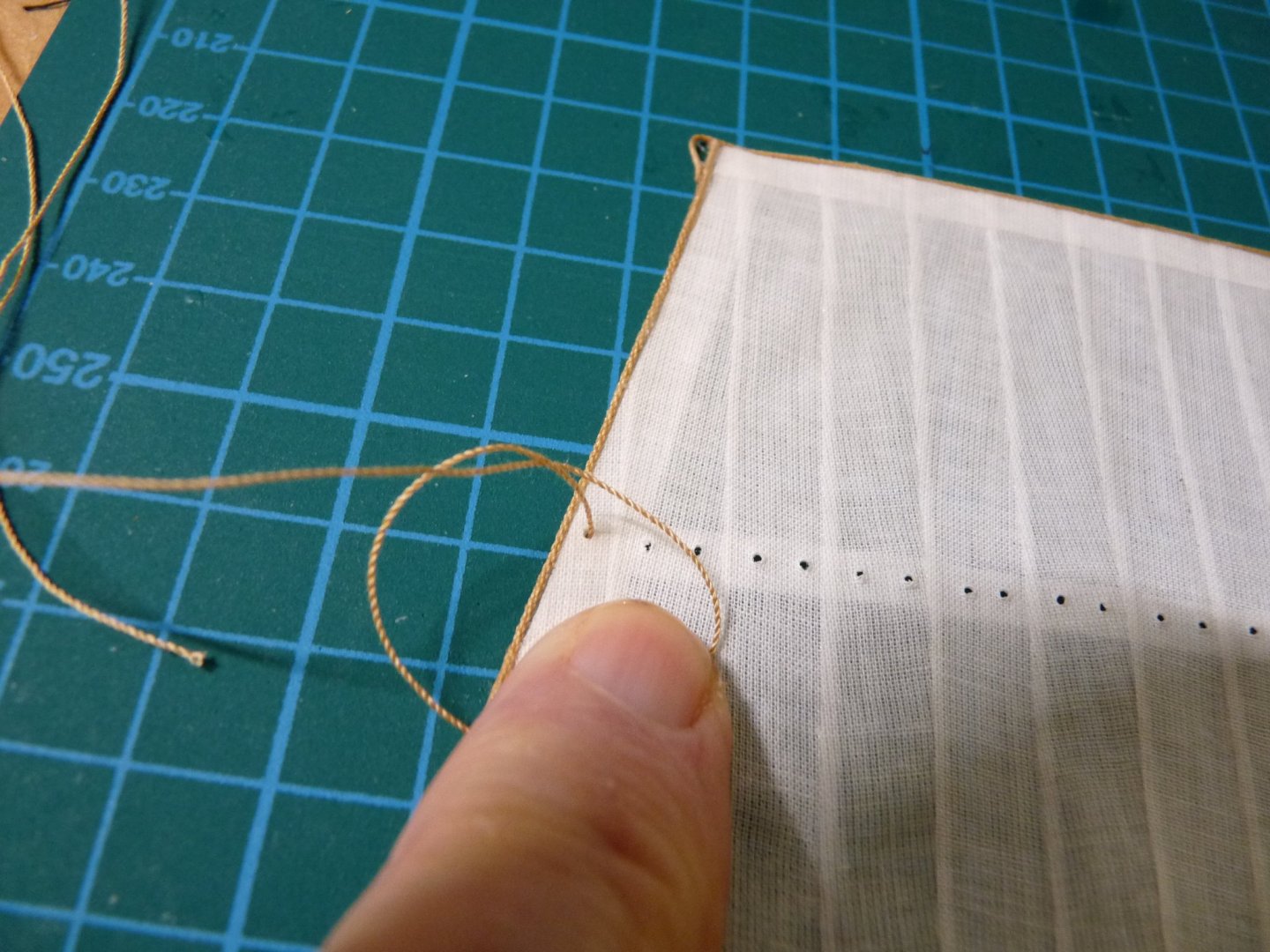
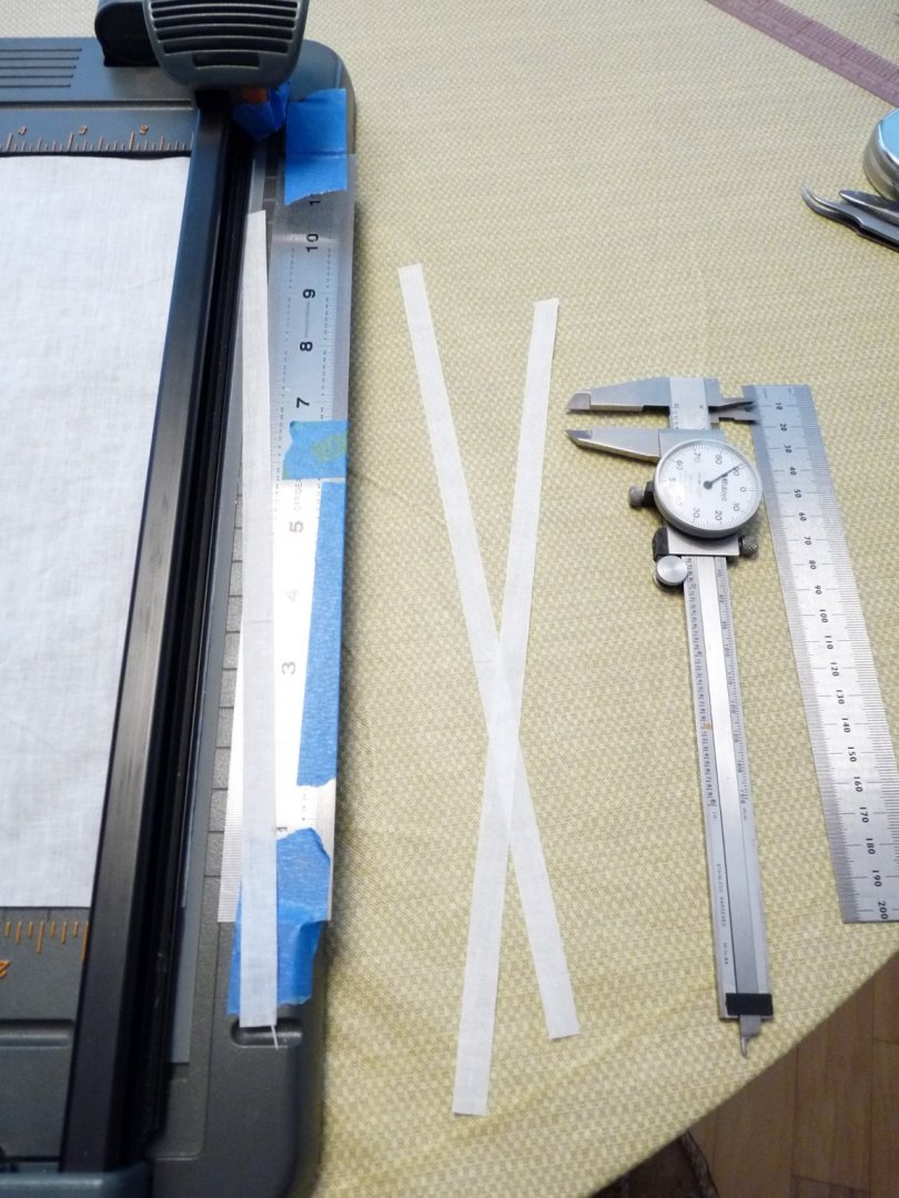
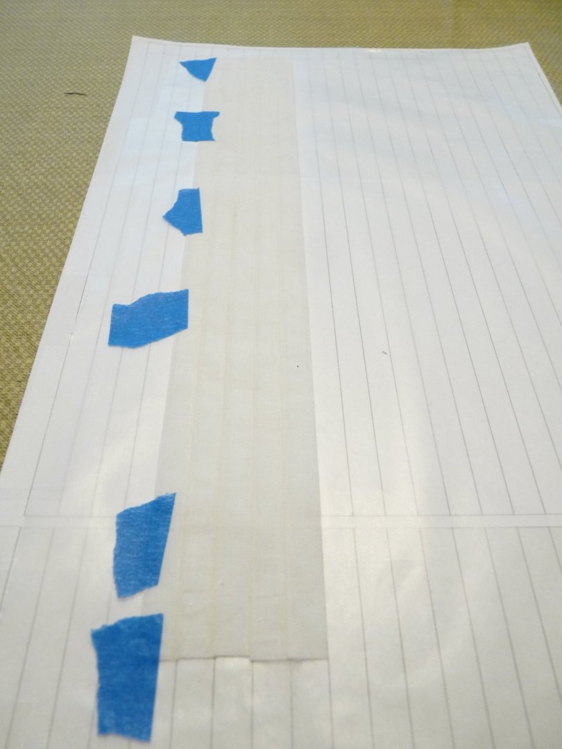
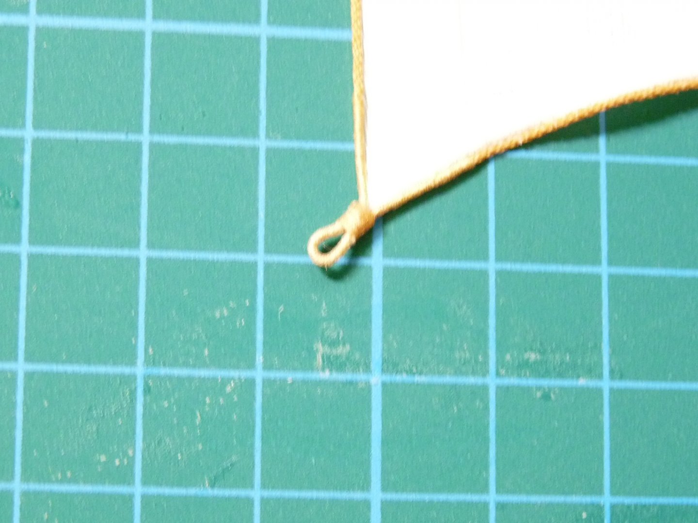
Just wanted to throw my two cents worth in here on this topic. I'm making Caldercraft's Victory in 1:72 scale, and along the way decided to put sails on her. Caldercraft did not anticipate sails, so many of the fittings and belaying points were omitted from the kit. Not sure yet if putting sails was the right decision. Nonetheless, I had made earlier models with sails that had sewn seams in a slightly contrasting color to the sail material, and was unhappy with the results as the seams stood out too much - were too apparent. At almost any scale, the actual sewing of the seams would be all but invisible; the overlap of the adjacent sail cloths would be somewhat visible when backlit. What I was looking for was an effect where the seams would only be a hint, not too obvious, and the sails not so thick that I couldn't form them to some extent to indicate that they were drawing. I wanted a fabric that was thin, somewhat translucent but not transparent. After many iterations, I settled on "lawn" cloth as the base material. "Lawn" is a corruption of "Laon", which is the French city known for this particular weave. As it comes, it is a little too transparent, so I used a 50/50 dilution of Elmer's white glue to close up the pores a little and make it stiff enough to handle easily. It was then ironed flat and sliced up into long strips to emulate the sail cloth width used in the 18th century, which was usually 2 feet wide. At 1:72, this comes out at a little less that 3/8" inch wide. I then glued them together with Elmer's with about a 1mm (.030") overlap, making a mat of suitable size from which to cut the sail. I printed out a pattern of suitably spaced lines using Excel, which was used with an overlay of wax paper on which to assemble the sail. An appropriately sized boltrope was then glued with white glue around the periphery, with served and marled cringles at the corners. Cringles along the leech or foot were added later and glued on with a dab of CA. The result is a fairly stiff, but capable of being formed after dampening, sail where the seams are represented by the overlap. It's not perfect, but to my eye much better that sewn seams. There are many details in the construction that I won't add here, but if there is interest, I can post a tutorial at another time. Here are a couple of pix.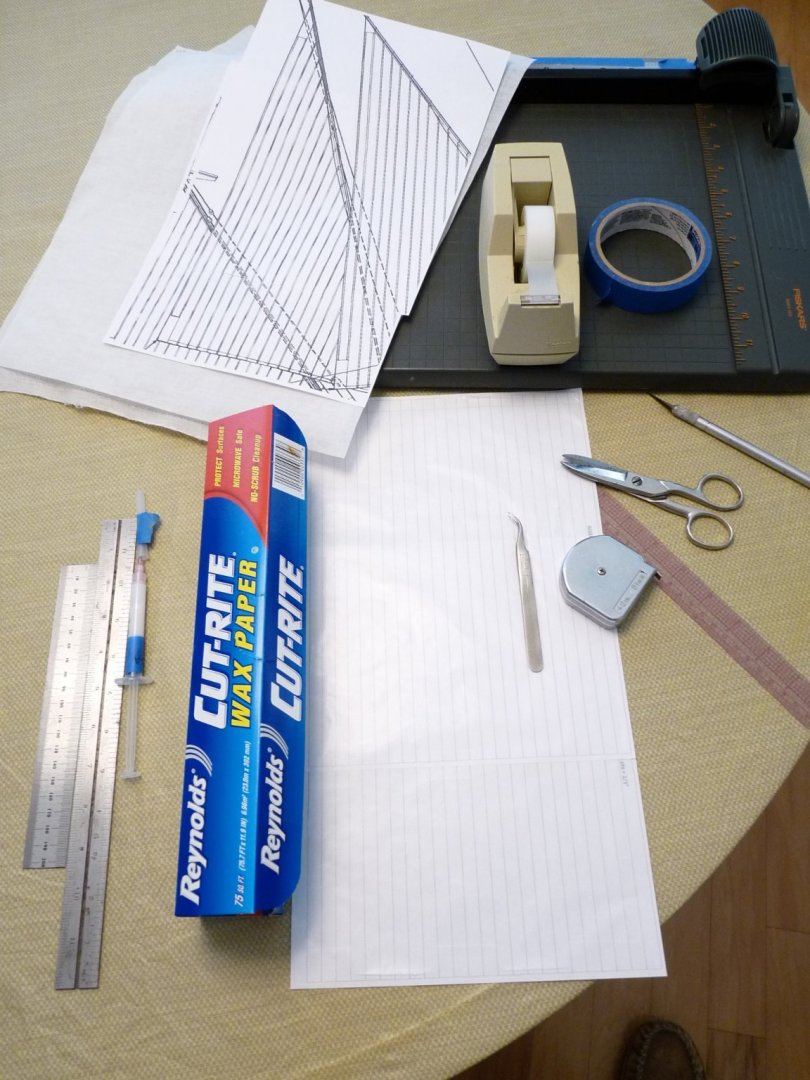


-
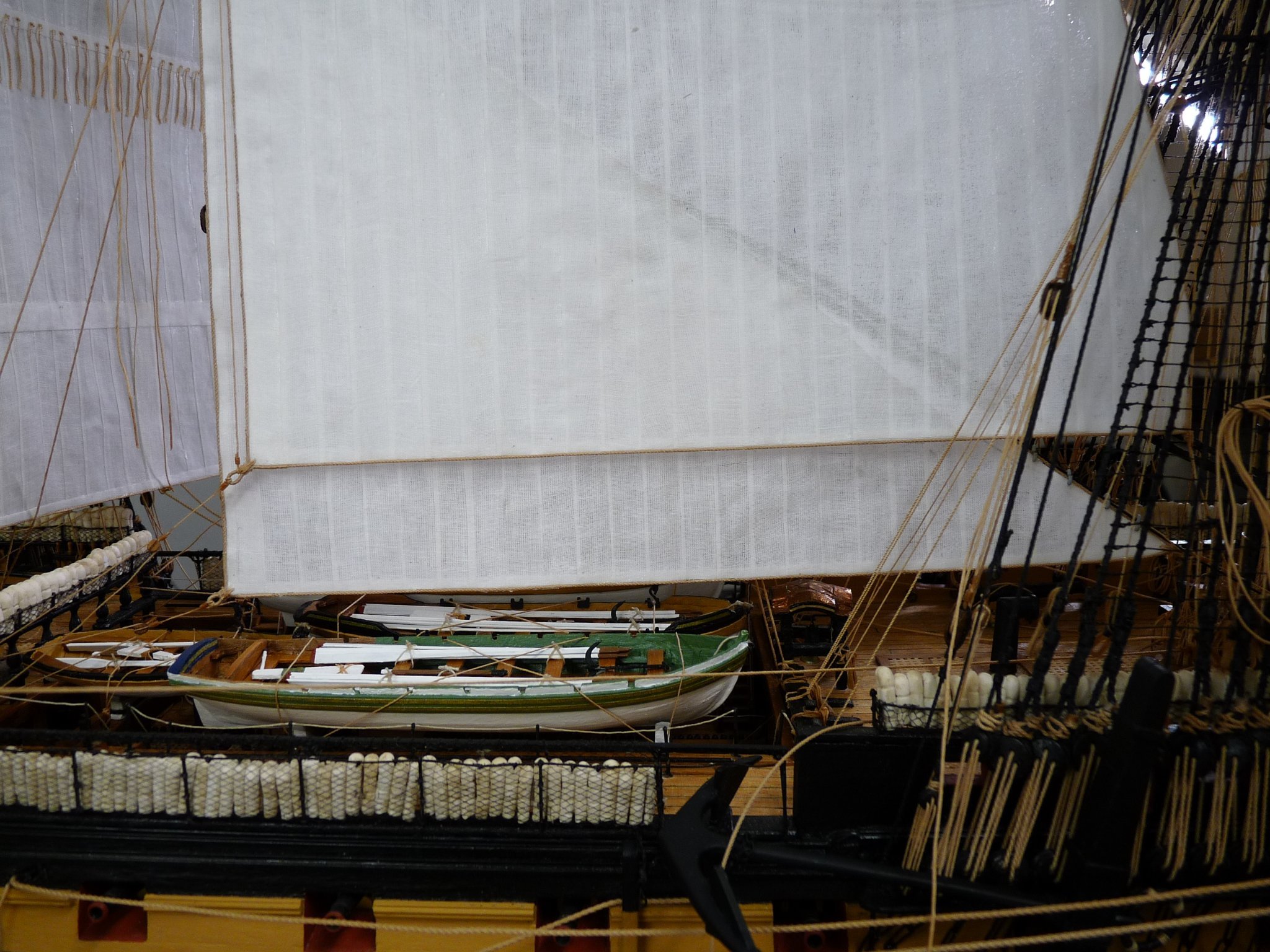
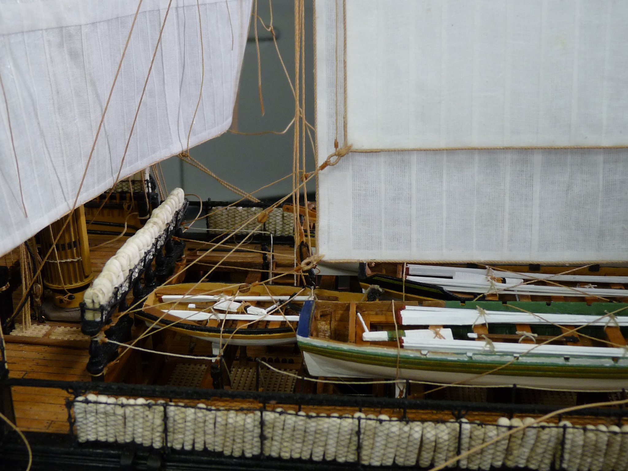
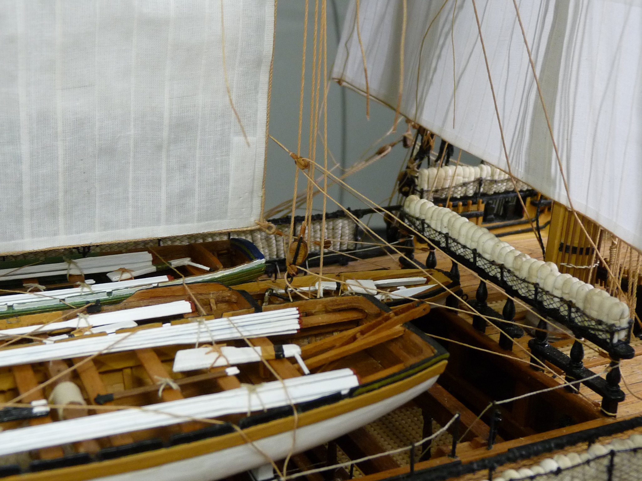
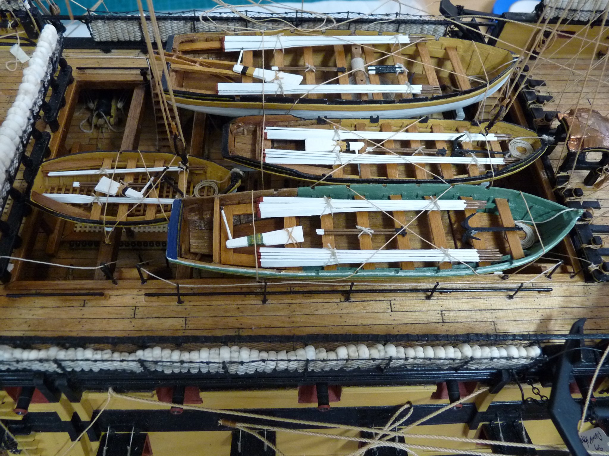
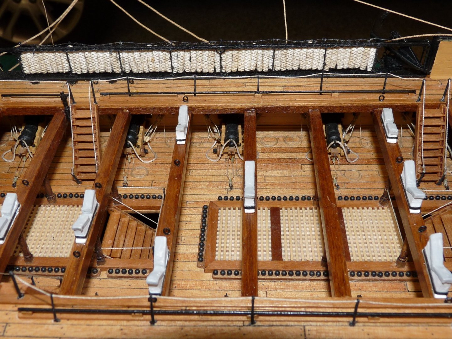
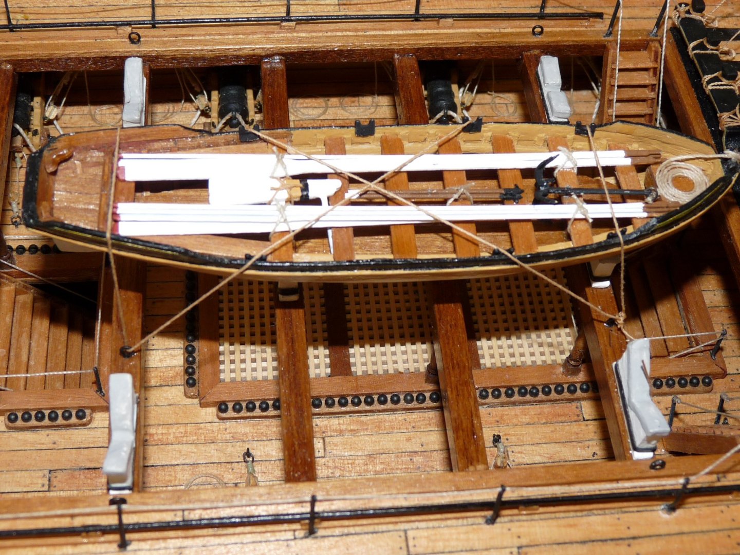
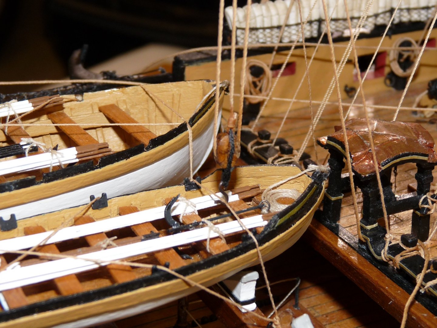
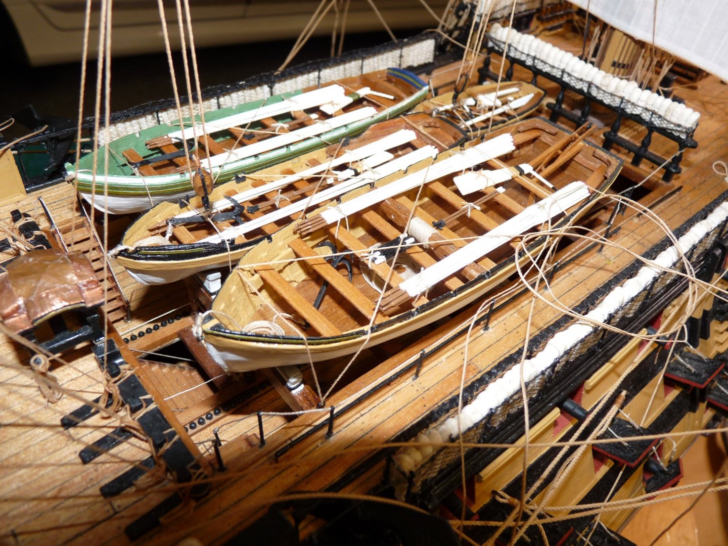
After I add the 2 lower main stay sails, the waist/boat stowage area will also be cramped and mostly inaccessible, so I'll add the boats now. The 4 boats have been made since summer 2011, when I had to be away from home for several months. The main Caldercraft kit was too big to take with me, so I concentrated on making the ship's boats that summer. I have resisted adding them permanently up until now, mainly because they are dust-catchers. My workshop area is located in my garage, and the dust level up til now was very high. I've had the garage floor epoxied recently, and now don't kick up as much dust, but still cover the model every night with some very light plastic to keep most of the dust off. Here's the last look at the unencumbered waist area, prior to adding the boats and their tie-down lines and tackles. Most of this will no longer be visible after the boats are mounted Here is the 34' launch being added to the boat tier. Now the 28" pinnace and the forward main stay boat tackle. Finally, the 32' barge and the 18' cutter, along with the after boat tackle.

-
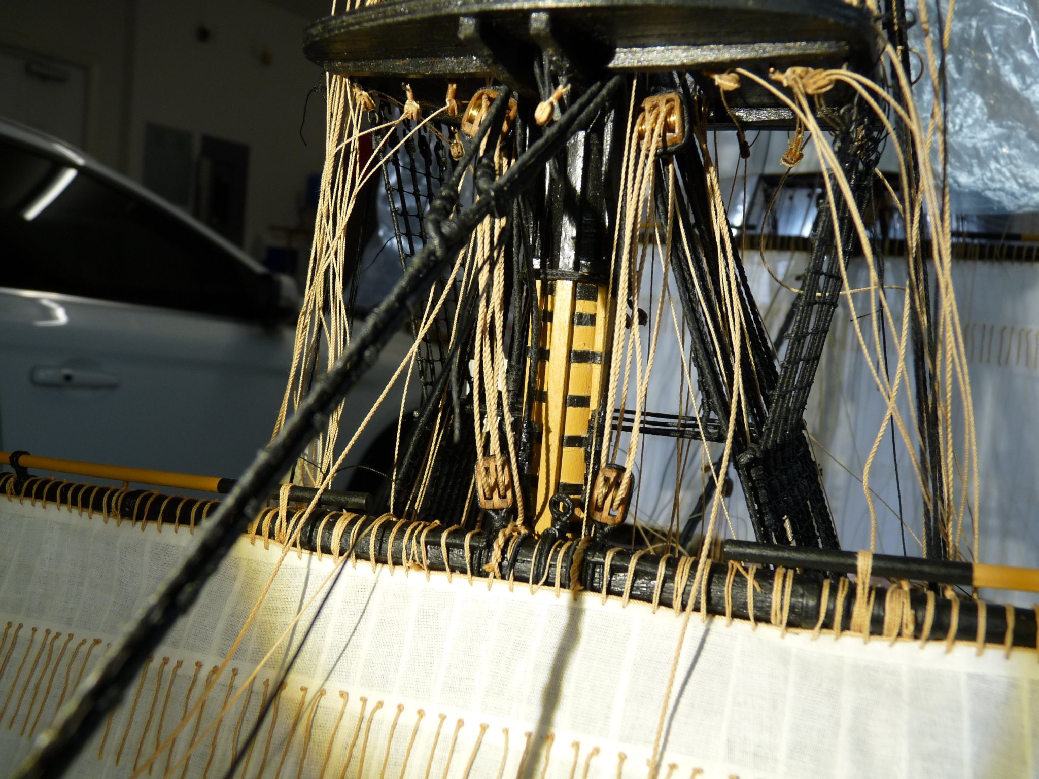
I am trying to get the belays at the fore mast foot completed, as an upcoming step, adding the main stay sail and the main topmast staysail, will almost make this area inaccessible. It is very congested here now that I have added the belays to the focs'l breast beam assembly (fore course bunts, leeches, etc). The stays for these two staysails are belayed in this area (note the bullseyes behind the pinrail). The main staysail, which by name would seem to hang from the main stay, actually is rigged to what was known as a "spring stay", which runs sort of parallel to the main stay, but terminates at the fore mast foot. This was necessary due to the fact that the staysail hanks would not be able to slide along the actual main stay because of the snaking between the main stay and the main preventer stay. I have extensively used Hubert Sicard's method of using what he called "zip seizings" on most of my rigging, which enormously makes tightening the rigging lines easier, and also lets one pre-rig lines while the zips hold them in place without glue. The main topmast stay belay is located on the bullseye behind the pinrail. Also, I have not yet shipped the topgallant masts/sails, and their belay points here and on the fore shroud cleats will be inaccessible after the staysails are shipped, so I must add them now and let the upper ends of these lines flop in the breeze until I get around to adding the topgallant mast. Attaching these line later at what should be their standing ends, will be much easier because of the zip siezings. This is the case for many of the running rigging lines, hence the jungle of slack lines that appear in the pix.