DONATION DRIVE - SUPPORT MSW - DO YOUR PART TO KEEP THIS GREAT FORUM GOING!
×

liteflight
-
Posts
206 -
Joined
-
Last visited
Content Type
Profiles
Forums
Gallery
Events
Everything posted by liteflight
-
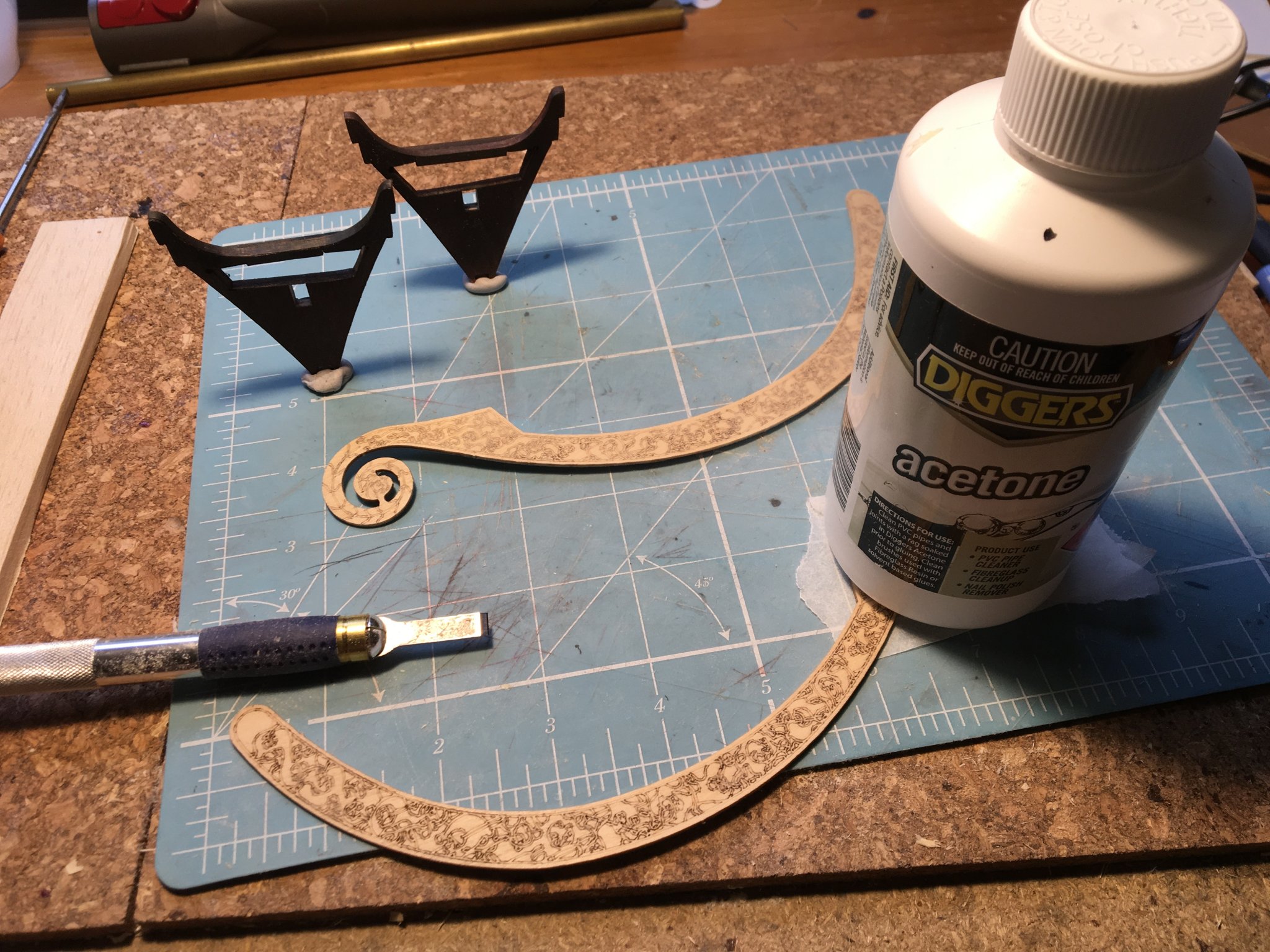
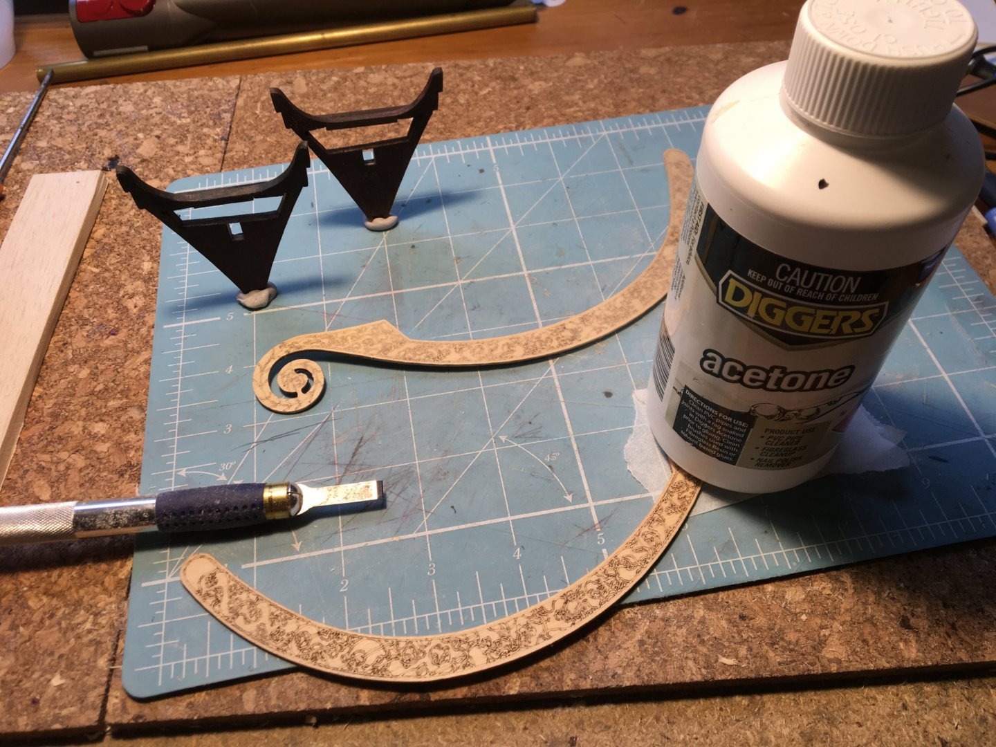
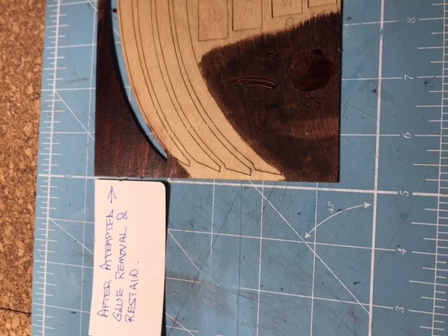
 A little progress! Slow but deliberate, I like to think. I have also decided that The Oseberg ship (needs a name) IS the personal ceremonial conveyance of Queen Asa and that the aforesaid lady is a Good Thing, and appreciates her Ship. I am aware about the debates, and I have decided that academics are doing what they do - arguing: and I will do what I do - imagining, building and learning! And one step backwards! The prow bend has returned! It will not be tolerated and will be heated/counterbent out of existence. In normal circumstance I would proceed smartly to Float-a-Boat (this is a wonderful name, especially when pronounced if rich Geordie - the dialect of Newcastle-upon-Tyne) and buy some 4mm birch ply and remake the offending part. After a lot of thought I am fairly certain that the distortion of this bit of ply is the cause of the "non-laser-cutting " of the end of the sheet where it resided. Probably this end of the sheet was jacked away from the platen by the bend. I will sort the bend, and NOW is the best time to do so, as the ply is now stripped of doublers and available for massage. Staining A bottle of stain in the hand is worth 64 theoretical stains on a shade chart, so I have proceeded to stain the faces of the frames. I have also covered the exposed ply edges of the end frames with pine veneer using my hot-melt technique. because some of the radii are small - in both directions - I have wetted the veneer, draped it into place and tacked it down with the "barrel" of the soldering iron - set to 200 degC. Then the veneer was applied over the whole area by mostly rolling the iron along so that the veneer followed the curves In the photo the rear frame was veneered with unstained veneer, and the front frame with pre-stained veneer. This may account for the colour difference where the veneer is fixed to the cedar insert. I have not tried to even the colour out yet, but I would not be too upset if it remained like that. Frame stringers I have decided to follow (faint but pursuing) the examples of Jack P and Von Kossa. They insinuated a frame between each of the kit frames and thus made the hull structure above the floor look a lot more scale. This is also essential if the floor is to look anything like the actual ship. The kit provides long Obechi planks 1.8mm x 12 for decking, and they are supposed to run the full length of the deck. They are supposed to rest on the tops of the frames, and be cut out to fit around the frames. Easy decision - NO! How would we bale when the Queen's picnic party was hit by a squall and shipped a lot of 'oggin which is then sloshing round in the bilges and making the ship terribly mushy? Have YOU ever carried a full baby bath after bathing your little darling on the floor in front of the fire? You have? Then you know EXACTLY how the ship feels when she needs baling, and your feet were warmer and better-smelling than the crew's! So we will have scale (ish) floorboards fitted between the frames. SO Floorboards level with the top of the frames means that the floorboard thwartships bearers have to be 1.8mm below the frame horizontal parts So The longitudinal 4 x 8 battens which stiffen the frame assembly before planking will have to be lowered by 1.8mm. I considered deepening the cutouts in each frame - but instead have marked and cut out the battens. I am now searching for my diamond needle files to tidy up the cutouts. Tonight I will read my Guru's build logs (again) to find out what they did to sort the floor levels. I suspect that JackP used thick enough oak veneer on the ply frame to raise the frame level, and I KNOW that he made the floor from thin white oak planks. During the "notching" process (razor saw and no 11 scalpel ) I discovered again why Obechi is off my Christmas list Huge and wavy grain - nearly impossible to make any sort of exact shape However these obechi parts are used in compression , and only functional in the early parts of planking to stiffen the backbone. Apologies for the messy picture. This is where and how they go. You can almost see (if you stand on tiptoe and squint) that the stringers are recessed below the horizontal parts of the frames. Nothing is fitted yet or glued, so the stringers are being retained in the frames by faith and friction. Scrollworks! I have commenced thinning the supplied 3-ply laser etched scrollworks. As supplied (3-ply) is 2.1mm thick. I have winkled chibbled gnawed delicately chiseled the rear ply off and sanded the back. Fairly successful once I discovered that A) the best weapon is a narrow chisel and b) sometimes I can find the joint line of weakness, and a lot of the ply comes off with zero force C) Not easy to hold the increasingly weak part while keeping all the fingers behind the chisel This is the favourite tool for this process I broke off one head by being hamfisted, and have therefore glued it back on - hence the greaseproof paper and weight! Australia and solvents, eh? Louie da Fly has a LOT to answer for! He sent me hi-res images of the actual scrollwork - which is actually beautiful intertwined supporting beasts and a dragon's head - and now I NEED to do something about this! The carvings are now a goal. Maybe not for this build, but perhaps the next!


-
I know the definition of an expert, so look you no! Indeed and to goodness But I do speak French like a native* * of Scotland
-
Ironic, I was raised metric and had to learn a lot when I got into industry Why not?? What is wrong with having peas? My bugbear (well one of my bugbears) is US and Imperial liquid measure. In a discussion several years ago about an absolute weight to calibrate a scale an American vouchsafed "A pint's a pound the world around" Full marks for rhyming, 7/10 for scansion. Nul Points for not being aware that a "pint of pure water weighs a pound and a quarter" and there are two pints, quarts floz. etc Mixing 2-stroke for my racing bike using American oil was pretty interesting, because the bottle gave dilutions in ounces per gallon, and my petrol came in Gallons Imperial. 50/1 isn't difficult in metric. Agreed, I'm sure there would be limber holes (or Nordic equivalent) to allow the water to reach a place where bailing was possible/easy. I have thought a bit about that, and looked at the bailers found at Oseberg. They are quite small, perhaps half a pint🤣 but not shaped particularly to access water in triangular spaces, or a lot of it. I assume that the crew would raise a section of boards around midships to aft on the lee side and propel the bilge water over the lee rail. Also the replica sailors would face similar issues, cos the replicas would ship water and leak rather like the originals, so Somebody knows and has lost knuckles in the process of learning.
-
Thanks, KrisWood I have just been reading about them. I should look before I post Erratum: Glue I have been calling the glue I have been using Weldbond, and it really is Titebond Original I rather doubt if there is very much real difference - but I should still get it right; it might matter to somebody My diluted PVA glue for attaching veneer has been dosed with a measured admixture of surfactant (Translation from the Andrewese - I put 2 drops of washing-up liquid into the needle-top dispenser and gave it a good shake) I suppose I could have used winter screenwash, but that would have involved a walk to the Garden Shed!
-
Steven, your question made me think. this is a healthy thing, and probably very good for me In this matter of the strange access holes I had been guided by Von Kossa who pierced the holes when completing the decking so I think I have perforated the correct frame. Still think it’s a strange place to have an opening, but probably there was so much water everywhere it made little difference. I imaging bailing was a way of life, and would be very surprised if some kind of shaped bailers were not found, perhaps left under the floorboards
-
Oh, come on now. Only 48, really! Peccavi! I have been told a million times not to exaggerate On the subject of the Scrollwork carvings. Yes, as you say they are Viking style with intertwingled beasts. How would it be if they were cut through in veneer ( or metal) and laminated onto a suitable backer sheet. I can see that being far superior to the current laser-marked creations, and perhaps with a little hand-rounding could be made excellent. My friend with several YAG lasers could do these in any metal, but regrettably not wood. We know because we tried. There are many firms, including several in Melbourne who will make greetings cards in real wood veneer which is, I think generally about 0.6 mm thick. (.024”), but some of them go down to 0.2mm. Hmmm, worth a further thought. While using these un-natural measurements foisted upon us by Buonaparte ( he has a LOT to answer for, including driving on the wrong side of the road). It did pass through my mind that at 25 :1 scale it means that 1mm on the model is 1inch on the real ship! Or an Imperial foot on the ship is 12 mm on the model
-
KrisWood Thanks very much for finding these. The serpents head is particularly fascinating, so that we can see how much interpretation goes into a reconstruction. I haven’t allowed myself to think about the shields yet. There is the practical issue that I won’t use the supplied shield boss, which I suspect is a glass bead and a small nail. No! Even if I can accept the laser-cut shield made of ply, I would want at least a hand hold (not sure what to call it ) and a hollow boss. I’m following your progress with interest. While looking for something else I found a good photo of a keel with its “wings” for the garboard strake which varied in angle from near horizontal amidships to parallel to the keel at the scarf joint with the carved stem and stern timbers. I’m sure you have progressed well beyond that digitally
-
Good question, Steven I will go back round this, but I think it’s ok. No worries if it ain’t! I will just have an under deck void and some useful practice still euphorian!
-
Steven Many thanks for the great photos of the carved ends. The wonderful Celtic patterns are clear, and it leaves me wondering just how to reproduce them better next time. My wife (and Admiral) loves to draw Celtic patterns and all things miniature, so I wonder---- No that's as unlikely as anyone carving 256 individual Byzantine rowers! I followed the thinking of Von Kossa and Jack P when they reached that stage of the build. Whether to round, whether to continue the patterns around the rounding. I'm thinking, I'm thinking🙃 I have laser-equipped friends. I'm not sure that ablation is the best way. Rather suspect that micromilling is the better option (and just today I read an Instructable on how to make a 3-axis mill into a 5 axis one) I learned poetry (and Ogden Nash) from my Mother. "Shake and shake the Ketchup bottle None'll come and then the lot'll" And I love his deep knowledge of the language, and then lovingly mangles it: "you want some flotsam: I gotsam You want some jetsam: I can getsam"
-
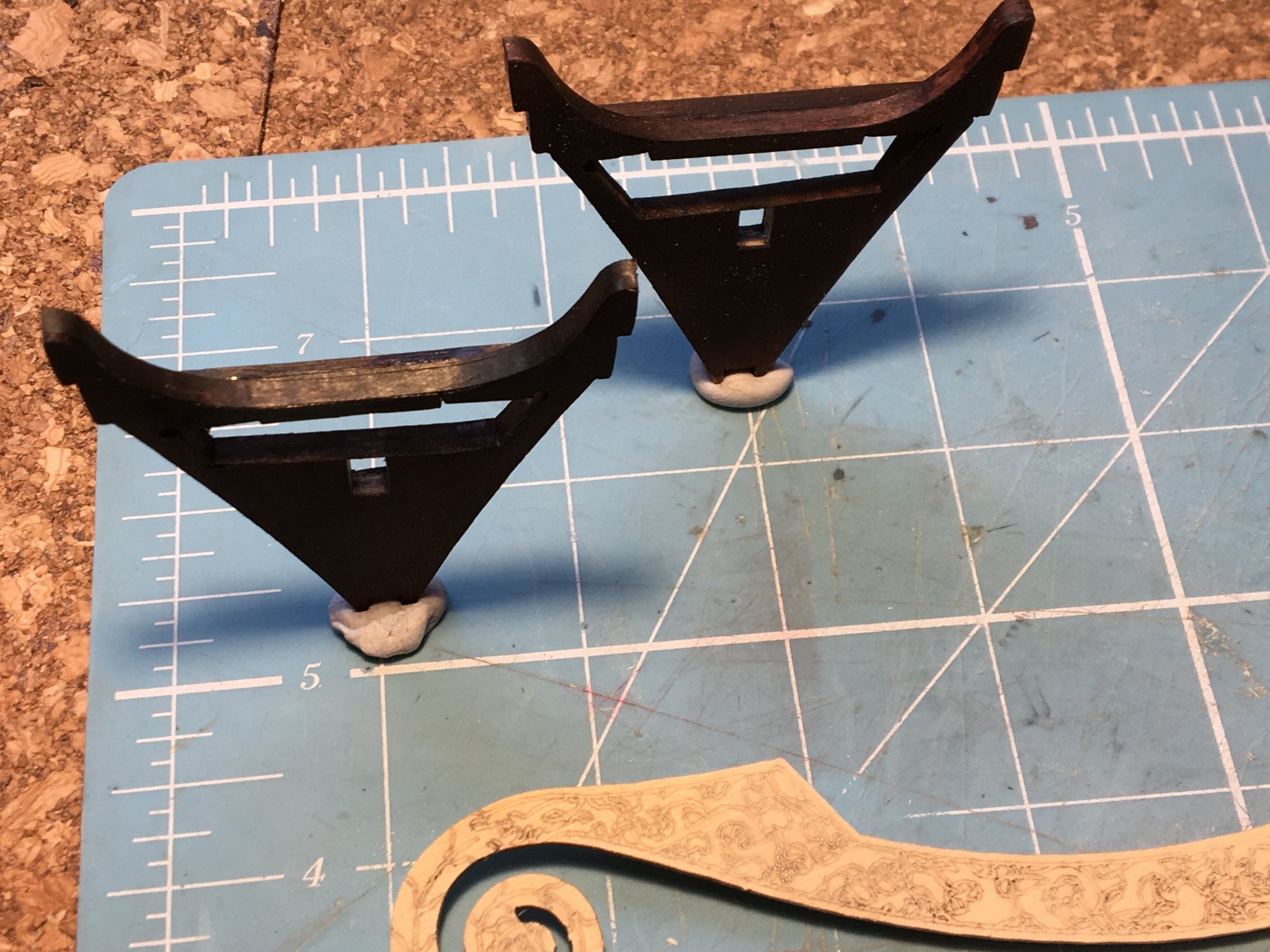
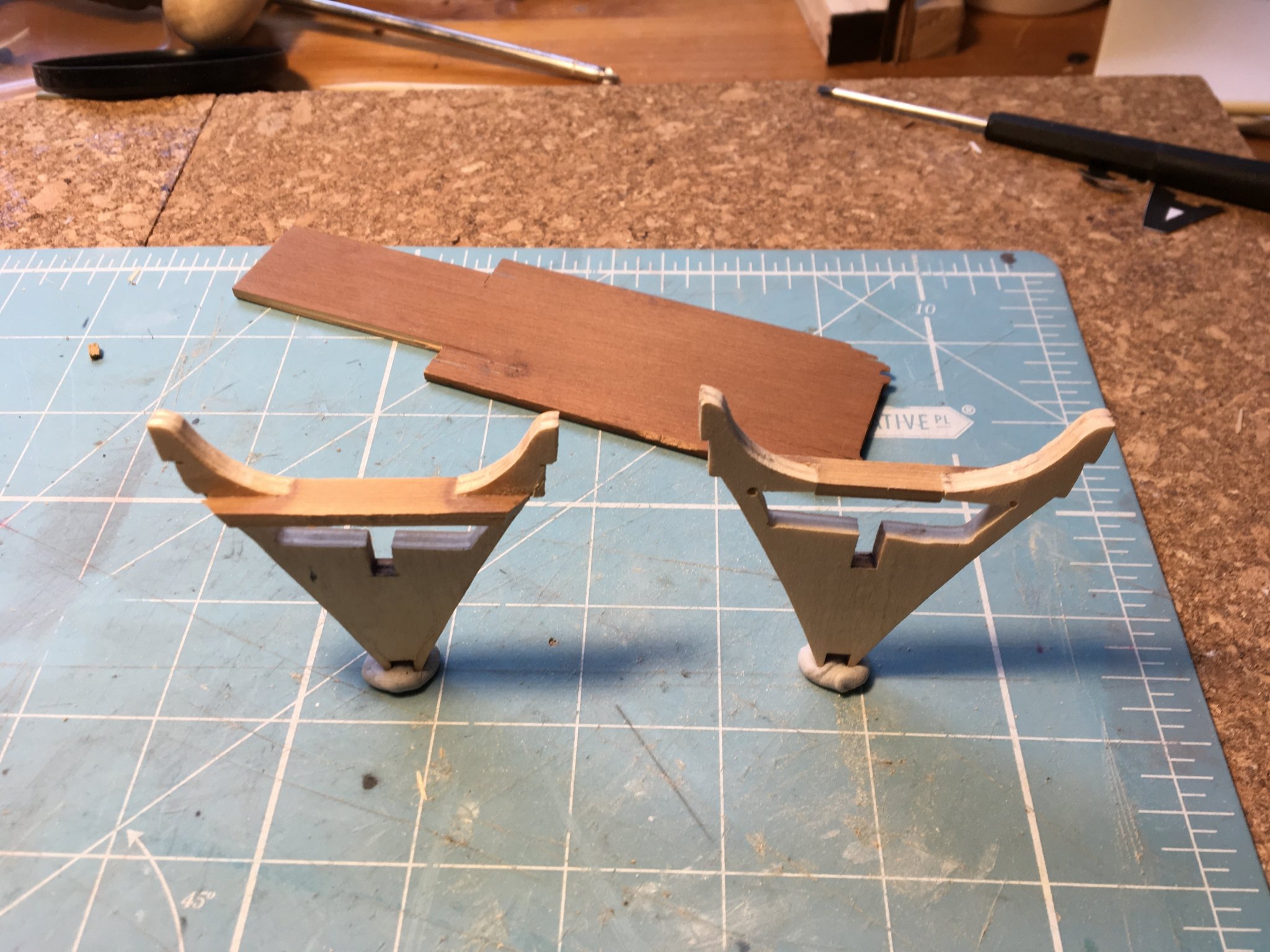
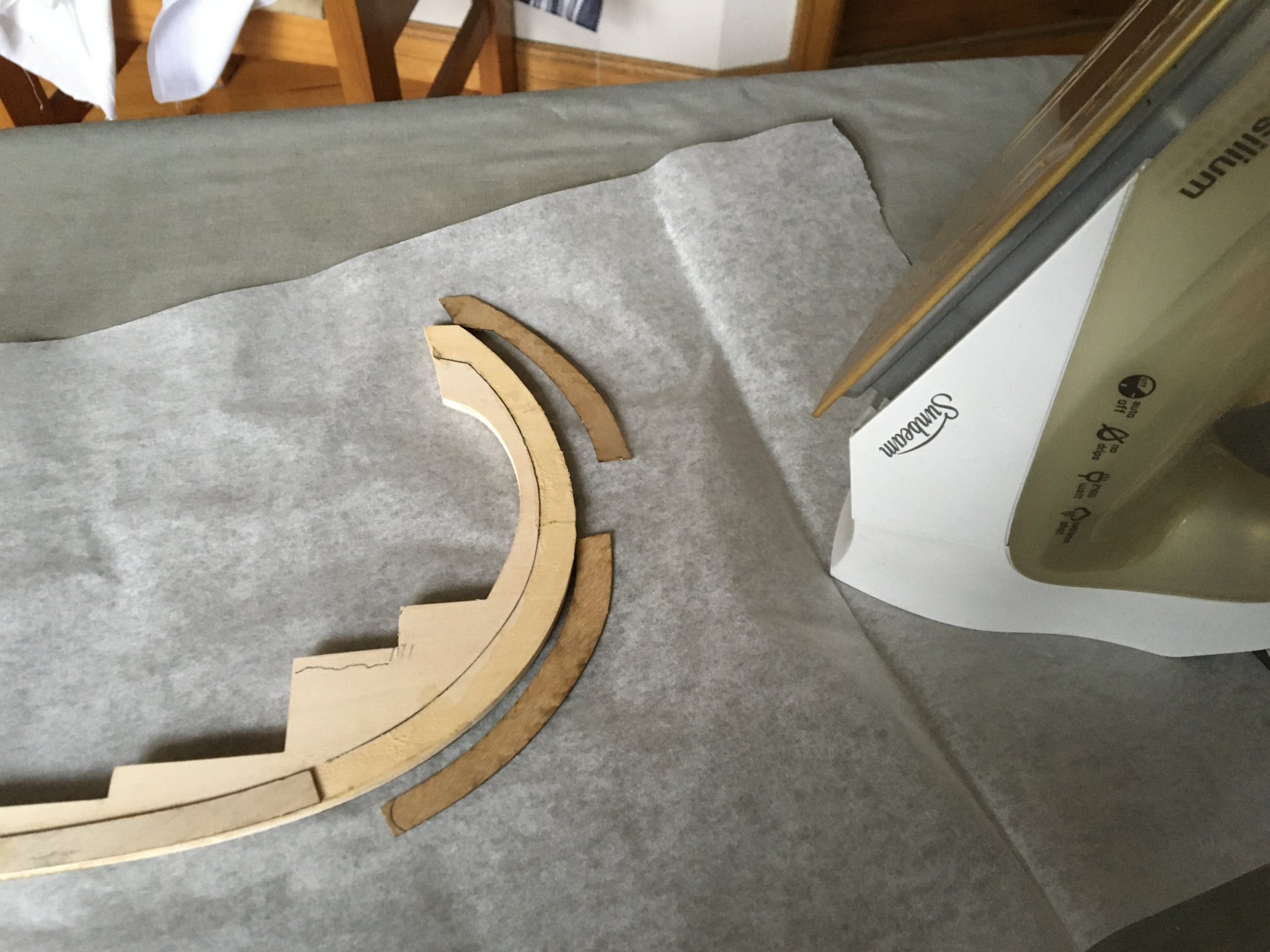
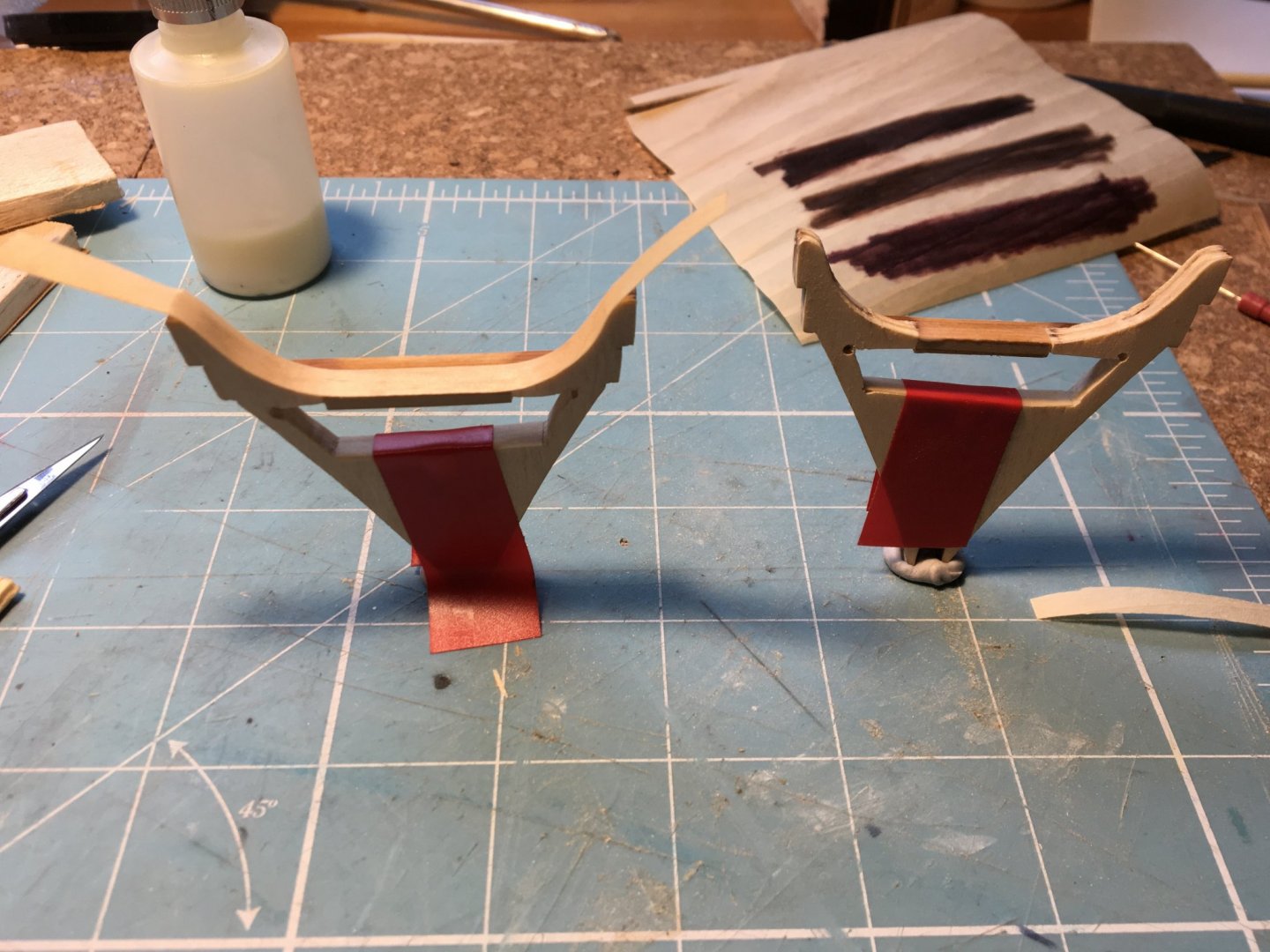
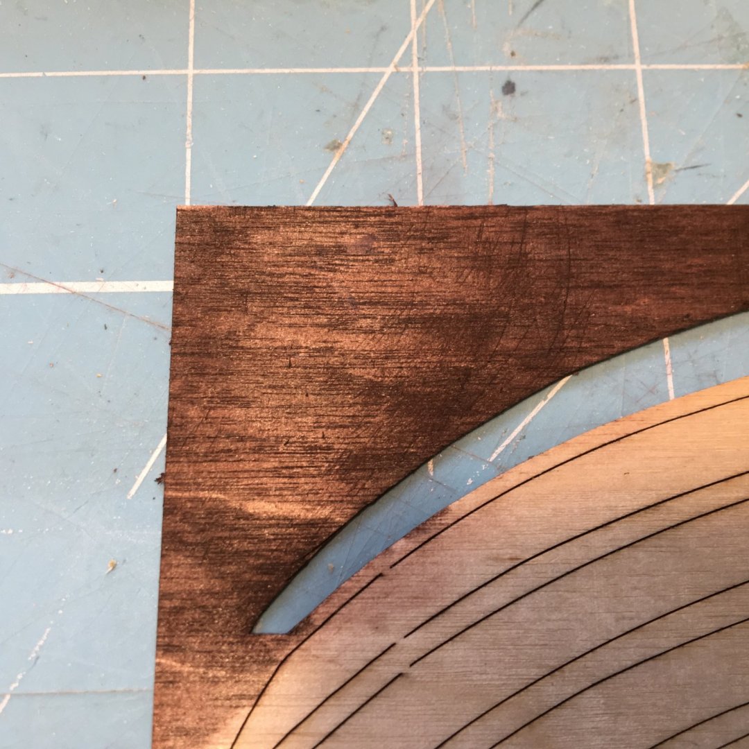
In preparation for fitting the frames to the keel, I have been carrying out the preliminary work which I vowed I would do before the ship was too far assembled. One area to prepare for is the Access holes , both bow and stern in the final frames, which are 4mm plywood So that all the cut edges would have to be veneered THINKS I have a thermostatic soldering iron which would be promising to veneer with in small spaces! Here are the two frames in question, pierced and with a piece of venetian blind let in because A) the ply was getting too thin at the top of the frame b) I needed a deck support for the small decks in the prow and stern Good News, the venetian blind material turns out to be close grained, pale wood, and with the distinctive aroma of a cedarwood! Veneering of the exposed ply edges is now happening. I have reverted to PVA diluted 30% with water for veneer adhesive. It is reluctant to "wet" freshly sanded ply so a couple of drops of washing liquid will be added to help this. The Left Hand frame in the picture above has a continuous bit of veneer applied, and clearly it will follow all the contours, both positive and negative. This is glueing, but I intended to use the soldering iron to attach the veneer (having applied PVA and allowed it to dry. Needle top PVA bottle just visible at the top of the picture This was originally a bottle of low-temperature gun oil that I used to lubricate my CO2 engines for model flying. I believe that such oil is now available for paintball guns, which have the same problem of low temperature lubricity. I will not be veneering the rest of the frames because they have cutouts in them for longditudinal stiffeners, and I would like the veneer to be continuous

-
This is my euphorian day, I will ring welkins and before anybody answers I will run away Ogden Nash, "No doctors today - thank you" Seems appropriate, as I have just made useful progress with Oseberg. All the woodworking glues are dissolved by Isocol (iso-Propanol) I read on MSW. So, having decided to remove the ply doublers round the prow and stern I had a bash at softening the (weldbond) glue with Isocol. Since the doublers form a gutter I ran Isocol into it and left the joint with a reservoir of Isocol for an hour. No noticeable softening or loosening of the joint Now I had read somewhere recent (and Authoritative!) that all the woodglues are softened by heat so I lit up the Iron and had all 8 doubling pieces removed in about 10 minutes Maximum heat setting, max steam The paper that everything is sitting on is Baking paper, which I folded over and ironed through to prevent the sole of the Iron from getting clarted up with Weldbond (even though I KNOW now how the remove it) One lesson from this exercise is that a tool more heat resistant than my thumb is a good plan to winkle to parts apart. Guess how I discovered that one! So - while feeling successful and Euphoric ; I heated and manipulated the bent prow piece till the ply was straight ! So the whole keel has gone back into the jig to cool and settle Obvious thought The parts could have been added just as easily by coating with glue, allowing to dry then ironing them in place! might be useful where a dry process is preferred - perhaps to avoid globs of glue! Might be a good way to go clinker planking on Osebergs!

-
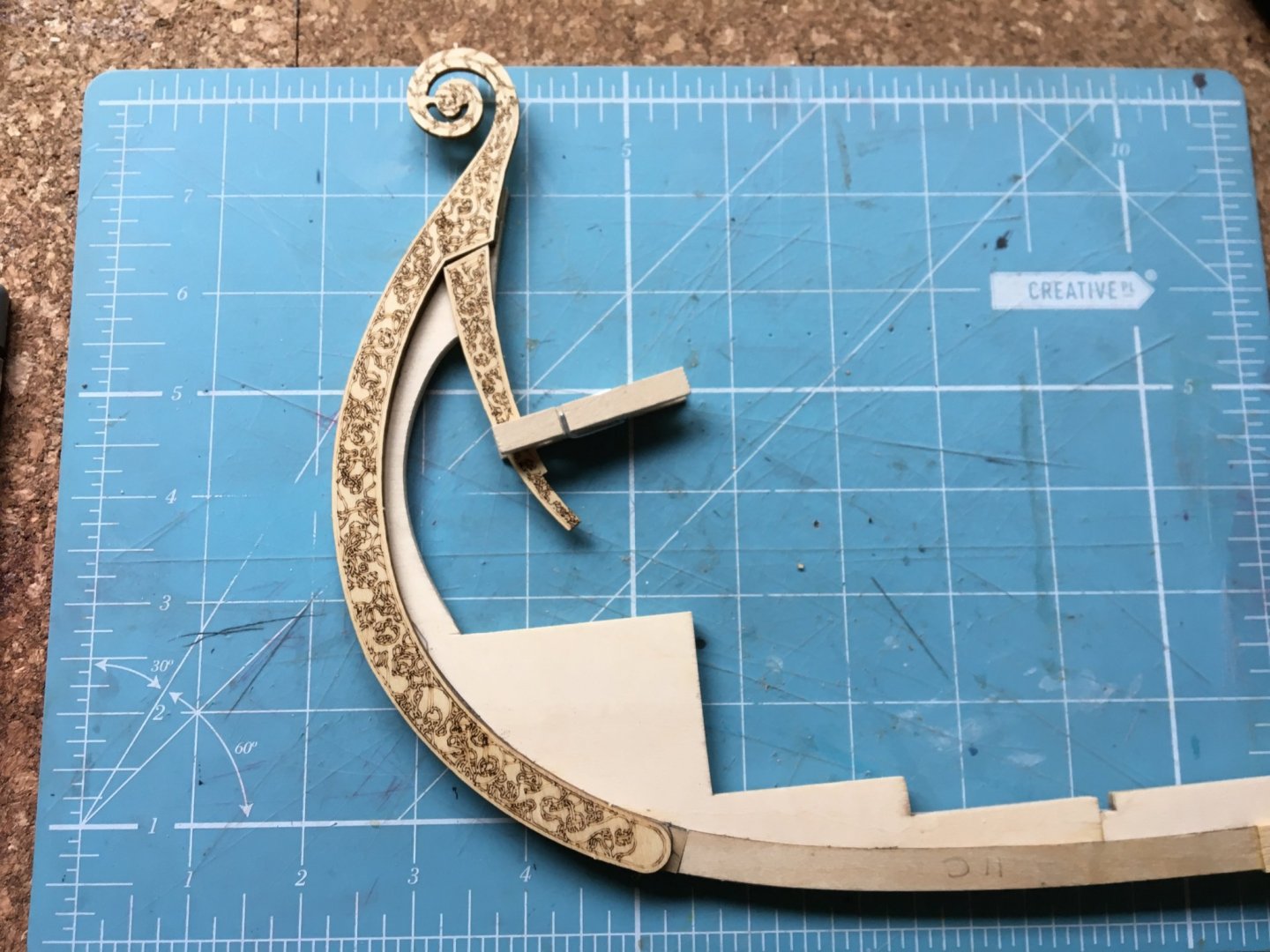
Steven. Warm thanks for your time and good sense in making this helpful response The kit really doesn't have conflicting instructions, really none at all relating to the ply scrollwork apart from the wee sketchie I reproduced This is the two pieces of the 3-ply scrollwork (2.1 mm thick) laid roughly in place over the ply doublers already fitted in accordance with the build book. When I am finished with this build the "book" will be filed in our extensive library next to the Greek Ferry Timetables* in the Fiction section *borrowed from Douglas Adams, author of the (increasingly inaccurately named) Hitch Hikers Guide to the Galaxy Trilogy Howsomever, I have decided what I am doing! I will remove the prow and stern doublers Fit the Scrollwork - possibly having reduced them to 2-ply (1.4 mm thick) Vertically extend the turnover jig to allow for the additional height (to avoid wiping off the delicate scrollheads) Stain keel , frames Fit frames Plank
-
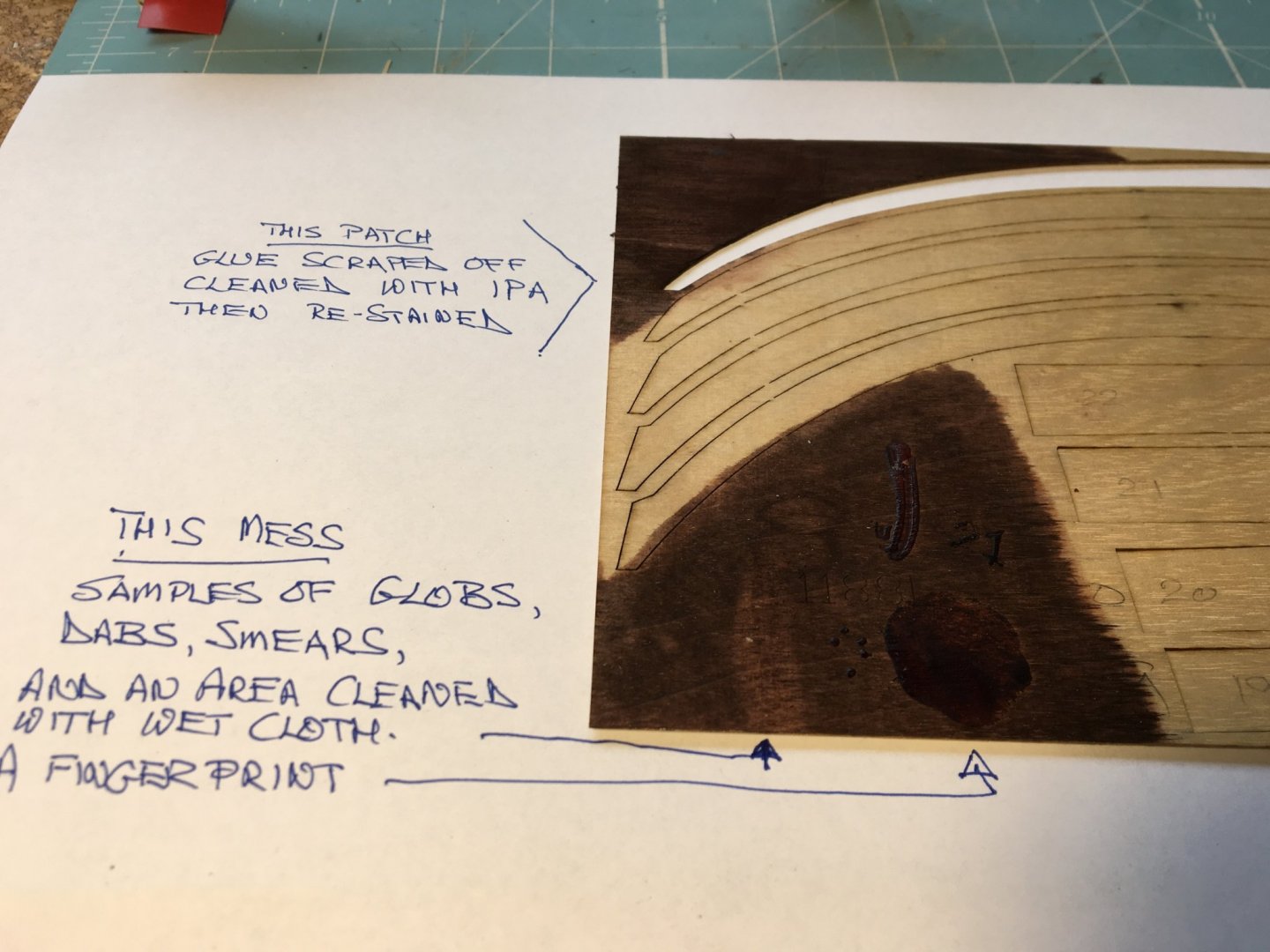
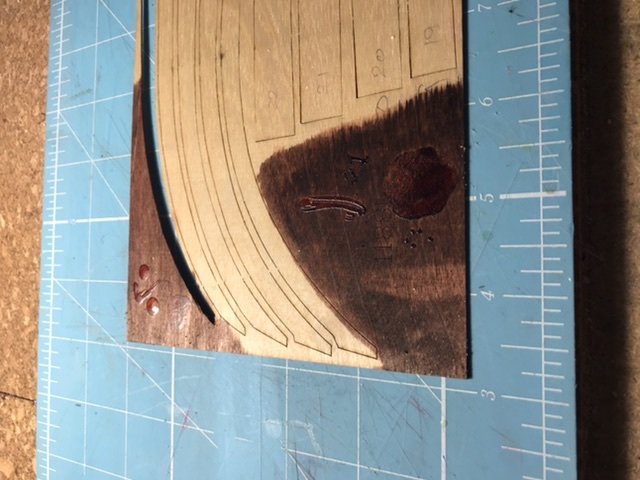
I can answer that with (a little) experience, Stephen Yes! Now the footnotes: A) the Weldbond had hardened for only a day b) I scraped the globs off then used rubbing alcohol to remove the residue C) Pic below shows pretty good success Just for comparison here is the Rogues gallery reproduced the right way up and with some added explanation Most of the ways of adulterating wood with Weldbond are attempted Sorry about the quality of the photo. its clearer in oblique evening light. I have decided to keep posts shorter and (nearly) on one topic!
-
Eric Excellent thinking with both the soaking/bending container and the binder clips Do you mind if I use the idea in future? My Oseberg actually has doubler pieces which effectively make the planking "end-stops" and should produce a sweet and smooth curve (It says here in the small print)
-
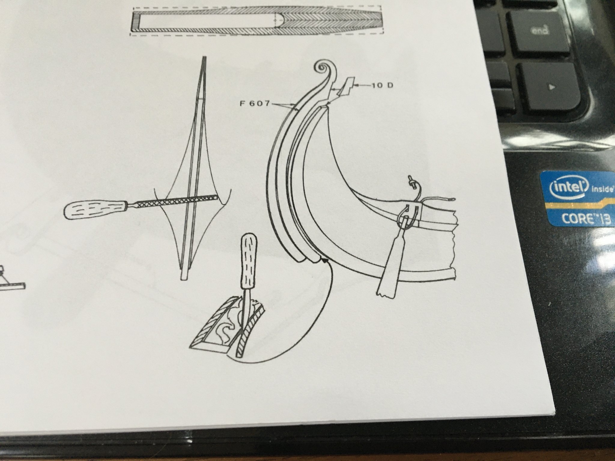
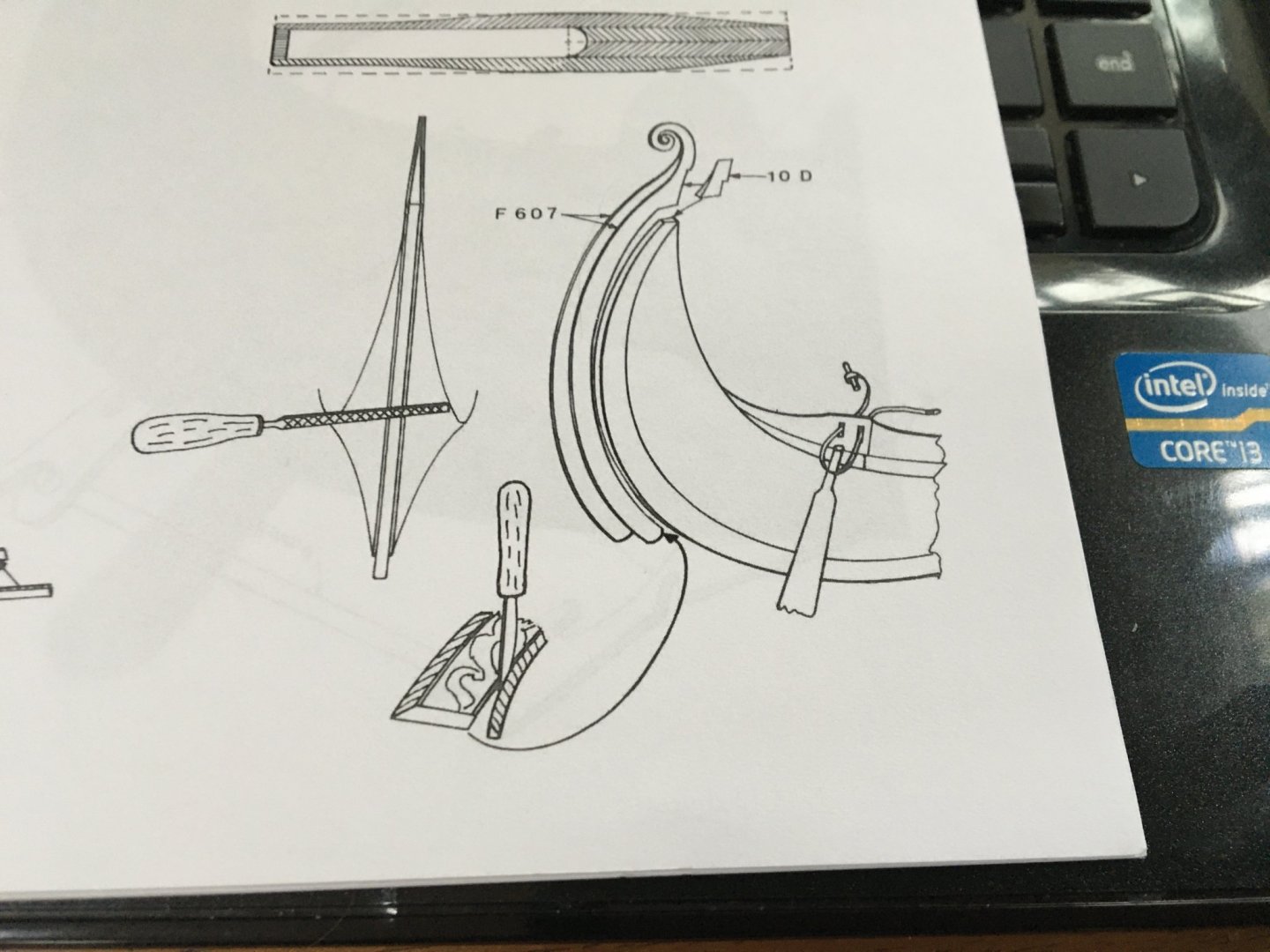
Thanks, KrisWood That will be helpful as I make progress (which seems to be a long way ahead) I am trying to work out wth the billings designer intended with the scrollwork panels. I will , of course, be guided by the excellent work of Von Kossa and JackP. Clearly I cannot fit the scrollwork right now, unless I remake the inverted jig - which would not be difficult. I think and hope that a tiny part holds the key to progress. The prow and stern are right now 6mm thick (4mm core ply plus 1mm each side) The scroll panels are each 2.1mm thick. Where they join above the prow/stern they would therefore be 4.2mm thick and would either be rounded off or squared and veneered. The little key piece (no 10d) is laser cut from 4mm ply, and is shown on the "instructions" as being tapered to a point at the upper end. This (to me) suggests that the 1mm ply doublers are to be removed in the area of the scroll panels (and others have said this too) so that they are glued to the core 4mm ply prow/stern. Then the piece 10d allows the scrolls to be glued together. But this plan extract clearly shows the ply doublers still in place! Which is probably why several people have reported thinning the scrollwork ply to enable it to fit without becoming excessively thick. Can anyone make sense of the sketch at bottom centre? I must be obtuse, but I find these sketches completely inexplicable! After all this thought and angst I realise that I would have been better off just building the ship. This is really my first boat kit, and I am accustomed to scratch-building without confusion from Danish sketchers
-
Hey, Stephen, that’s a good saying! I have a friend and former colleague who uses it in the Slovenian language. Guttural but still true
-
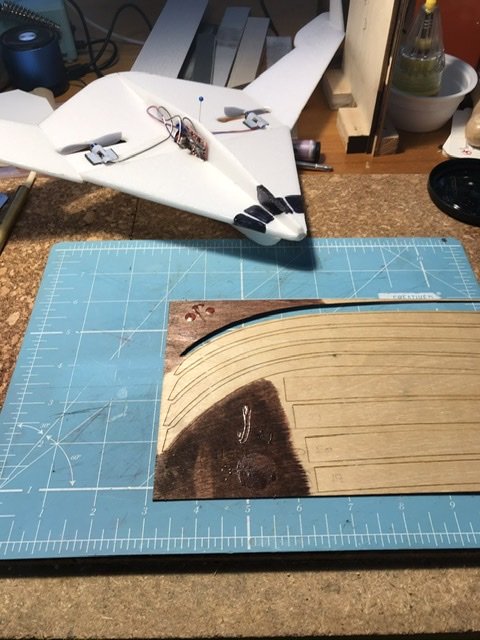
“Everything in moderation; including moderation” is my watchword. Thank you Stephen. I have taken note of your excellent and assiduous rowers and their different, but muted garments. Yes, I know that dyes and pigments are different in type, but I expect to be aiming for a range of cheerful, artistic and potentially authentic colours on the shields, and possibly as accents elsewhere. Currently I have no plans to carve a crew of rowers, but I would love to learn a new skill. Speaking of rowers and seating; when I commenced Osberging I had believed that Viking crews sat on their sea chests (probably, I thought, on a sheepskin to minimise chafing and saltwater sores). I did not even know that there was a debate about it! “If you can’t measure it, it’s an opinion”. Probably Lord Kelvin. It sounds like his delicate, diplomatic tones. Today I have been trying to measure how much of a problem to expect with rogue glue. I put large globs, smears, Fingerprints, dots, etc on an edge of the Ply sheet where the strakes are nested. I also tried my usual cleanup of a wet cloth to remove recent glue. Glue is Titebond original Bother, the iPad operates completely differently and rotates the iphone pictures. I post more explicable pictures when I get to my laptop I also made a blended-wing aircraft for indoor flying when my copy of Aeromodeller arrived and inspired me Well, who knew? The resident format of two of the pics has led to them being rotated 90 degrees, but not the one with the plane in it. I will rectify ASAP Tentative conclusion on glue. It will be a problem, but not insoluble, if I stain after assembly. Staining before assembly is the better plan, but demands that I plan ahead enormously. So I aim to stain everything, and let it dry completely before assembling. I will still remove as much glue as possible while it’s wet, but not fash mysel’ too much if some glue has to be removed Rubbing alcohol Works as well on globs of glue as it does on mistakes!
-
Good thinking, Eric Correct appearance with no loss of integrity. Win-Win! I have been looking at the scarph joints shown here. If I were a Viking shipwright, I would arrange the scarph joints so that they were "trailing" ie the raised edge on the outside facing the stern (rather similar to coppering on a ship, and any joint on a plane. If this is so, then this view is towards the stern I will go and check on those sites. Perhaps as I grow up I will check before posting But it doesn't affect this build
-
Thanks, Binho That's very interesting and blows into the weeds at least one thing I was taught as a nipper. I am reading the Woodland treatise with interest - thanks for posting it. I have also been reading material about the Skuldelev ships (and other finds from this era) and would not have asked about where the oaks grew if I had done my homework. I can see that I will finish up with a splendid static Ship and a store of knowledge. Shield colours: Yet to be faced! My top-of-the-head feeling about 11thC paint is that it would have been prone to being scuffed, fading in sunlight (remember sunlight, anyone in the southern continents?) and would have started out matt (because the pigment particles would probably have been in a range of sizes) and become more matt with time. So the array of shields would have been faded, muted, matted and non-bright I still have to read and digest the colour information the Binho posted in his build log (sorry, havn't succeeded in "quoting " this here, but I will) Found a useful resource from the Danish National Museum. The actual scientific article is only in Danish, but there is a good article on Science Nordic about it in English, including a color palette with a description of each pigment and the presumed relative cost. https://sciencenordic.com/denmark-history-society--culture/how-to-decorate-like-a-viking/1455997
-
Thanks, Balclutha and Eric The state of Victoria is in a condition of stage 4 lockdown, so it is not possible to go and buy anything except food and pharmaceuticals So I am working with what I have in stock. Certainly the mahogany can be discounted, but I would like to try Oak and Antique in the same range. It is possible to order online and collect, or have it delivered - so I expect to gather an order for house, home and hobby and have it delivered. As an aside I have just looked to find out what Tasmanian Oak is. And, not surprisingly it is one of three related species of Eucalyptus! And thinking of oak, and the recovered Viking ships. We know the dates when the timber was felled, but does anyone know WHERE the oak came from? Dendrochronology would identify the area. (Ah, yes, one of the Skuldelev ships was made from Irish Oak) When I was a nipper I was taught that common or pedunculate oak (Quercus robor) was a Roman import to Britain, and is a Mediterranean native. This is not necessarily literally true, but even if it was, there would still be time to grow a lot of oaks in the areas of Roman occupation (basically up to the Rhine) in time for late viking shipbuilding. Certainly trees are rare and valued in many of the "viking" lands. We live in a cool part of Australia, but semi-tropical nonetheless. Our street has a lot of European oaks , and one was recently felled and cut up. The growth rings were 3 to 5 mm apart, rather than 1/3 to 1/2 mm that I am used to from this species of oak! Not trees to make Victory from!
-
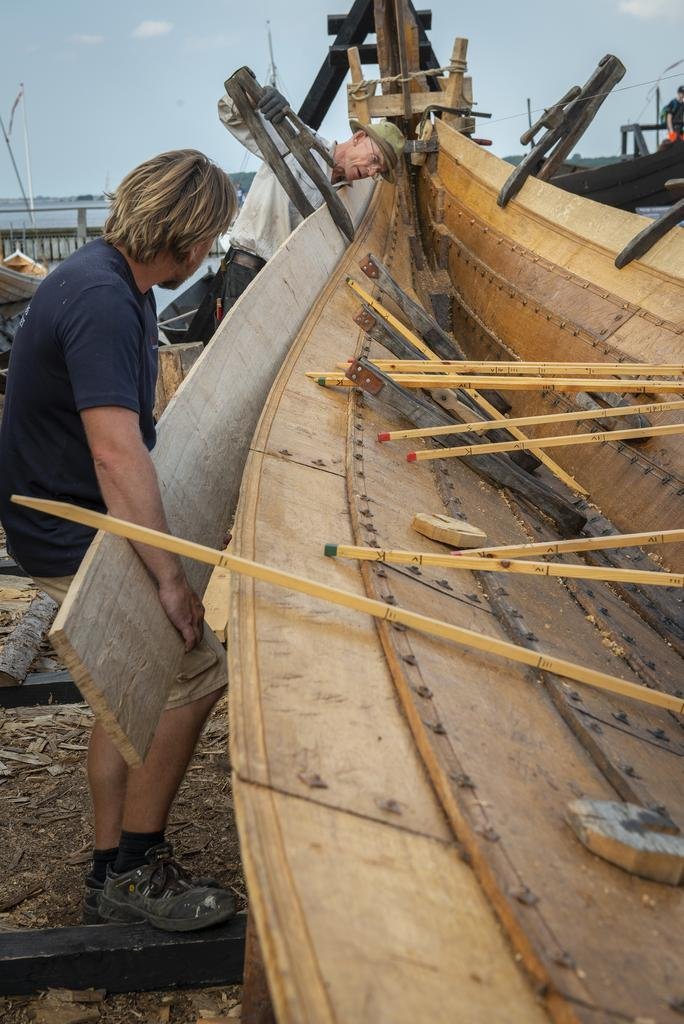
Don’t know if it helps with the scarphing question, but I recall seeing a video of a full size ship of this type being planked. The planks were bent and held by wooden clamps until rivets had been fixed. The planks were joined with a short scarph (not much longer than the thickness of the plank). The joint was sealed with something fibrous (?horsehair ) and something goopy (a blackish tar-based mastic?) I don’t recall any rivets or reinforcement on the back of the joint By the time the next strake is fitted and rivetted the joint will be well supported on a clinker hull My big Oseberg shows a short 45 degree scarph in each strake, and I never thought to look on other people’s build logs to see if they lay on a frame. There has been comment on the fact that all the joints land in a small area roughly amidships. Perhaps it’s a non-event, and that is why it’s not mentioned in the logs?
-
Thanks, Steven That echoes my current thinking. To facilitate the sailing version I will trace the frames ( I have already photocopied them) then veneer them and rub it down/stain and assemble to the keel There are 2 obechi lengths 4x8 mm which join all the frames, and when glued in these will strengthen the whole assembly. Deck levels I have already decided that I will fit intermediate frames between the ply, kit, ones, which are 4mm thick. I have a (huge) supply of lime wood from salvaged Venetian blinds, and this is 3 mm thick. My current view is that this will look ok, especially since I plan to make these as minimal timbers fitted to the strakes. Not describing it well. I’ll sketch what I plan and post it here My veneer cover has virtually no thickness. I want the floor planks to be level with the frame tops, so the bearers for the floor planks need to be lowered by 1.8mm or so below the frame tops. I plan to use something like 1.5 mm square to support the floor planks Again, easier to sketch than describe I make all my drawings in LeftyCad
-
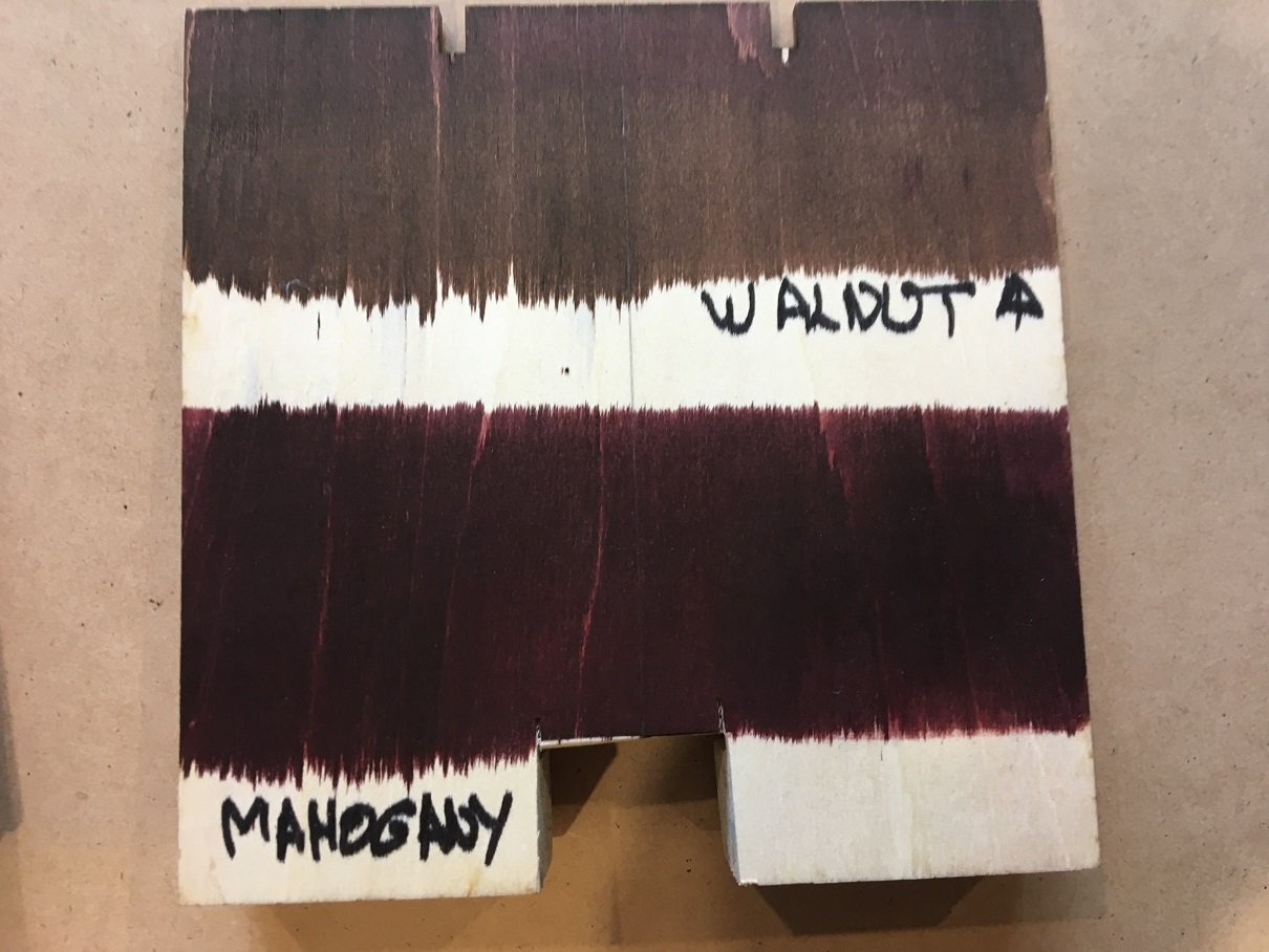
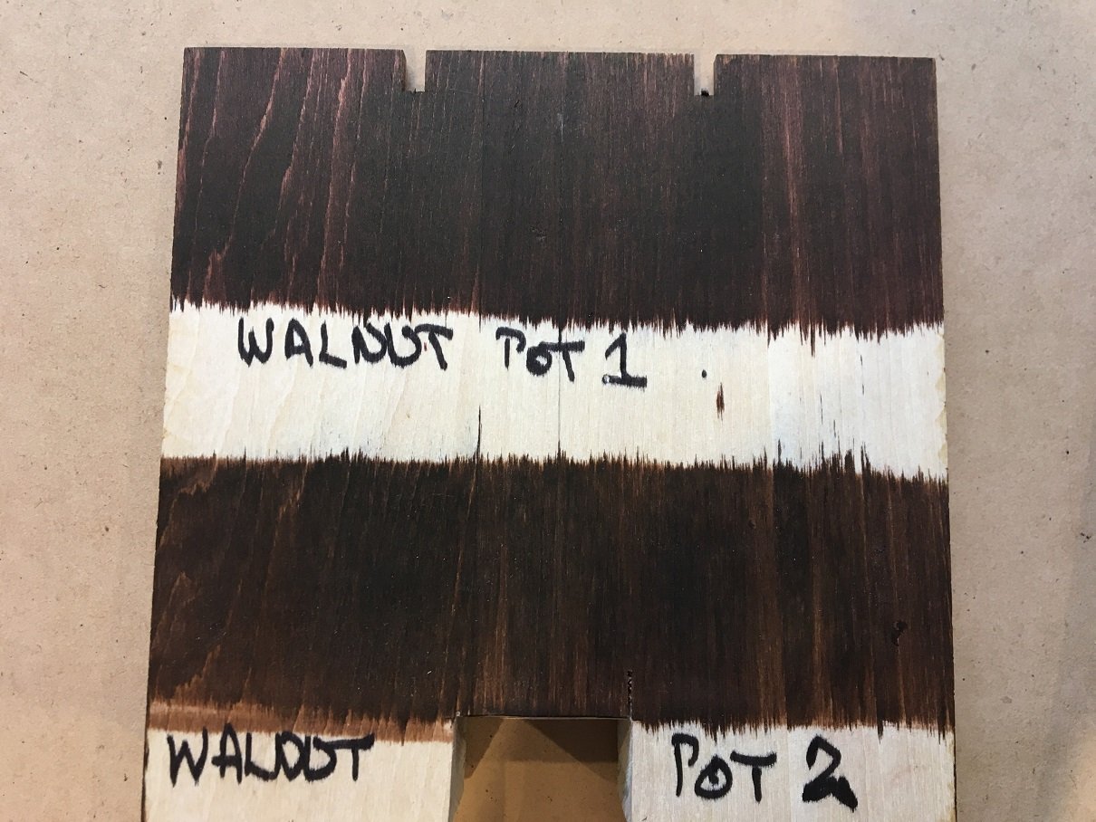
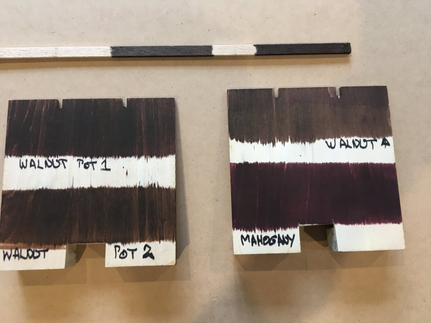
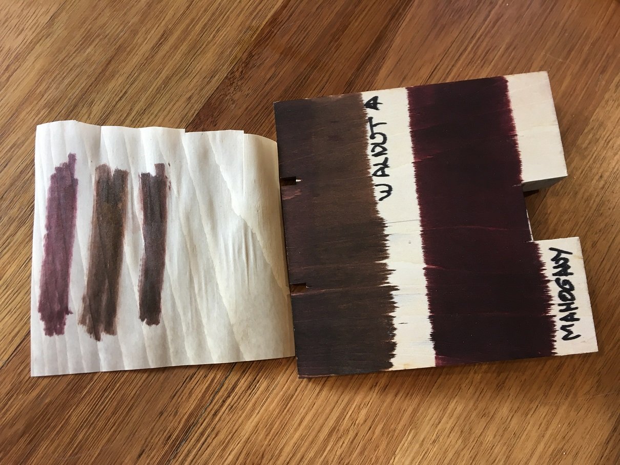
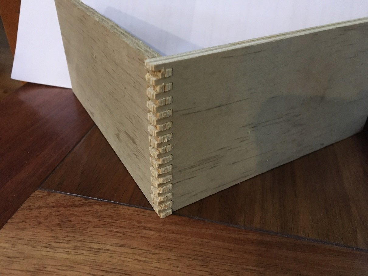
Feel free to vote for the stain colour you think most appropriate for a display model of the Oseberg longship. There should be some more stains to try before the first staining. In the course to trying these I have discovered: These stains are soluble in Iso-propanol! As I discovered by spilling some on my cork building board The narrow bottles ALWAYS get knocked over and spilled I now know this and prepare the area, and keep them upright in a deep container padded by cloths I applied a coat of stain to the 4mm ply that the frame is made from. The large parts of the turnover jig are perfect for this I have two bottles labelled Walnut and one labelled Mahogany These are the two pots labelled Walnut, but I have a sneaking suspicion that I used one of them to trial-mix in a little Mahogany I also stained an Obechi strip and some of my micro-veneer I'm distinctly chuffed with the behaviour of the veneer, because A) it took the stain sweetly, and B ) I was able to iron it flat without the stain misbehaving (or staining the sole of the Iron!). Thank you GladBake (baking parchment) So there we are. The stain has been applied, and fully dried. I expect to be able to glue the stained timber as easily as unstained. The experiments with intentional glue contamination can now commence! Why does the veneer (0.2mm thick) need to be ironed? Well because it was bought rolled and stapled into little cones for use as dainty holders for something like sweets (US=candies: Lincolnshire = clats) So the veneer needs to be flattened by ironing or similar Jack P used white oak veneer to cover the ply end grain, and since no mention was made of thickness I assume it was 0.6mm (25thou) which is more-or-less standard (I am told). For Jack and Von Kossa the veneer was made to follow the concave curves on the frames (using Packing tubes already!) and the remaining part of the frame covered, I think, in separate pieces of veneer I aim to cover each frame top edge in a single length of veneer since My veneer is thin , The tops of the frames are rounded off and I expect the veneer to be able to follow the rounded curve. Its rounded because there are no square corners to fall against in my Longship! I have experience of this both as a boat-user and full size builder of marine equipment, I said that I was chuffed earlier In fact my state is "chuffed to little Naafi-breaks" because I have just made my first box-joint This is made with scrap ply, but now I have a working jig, and the world is my lobster!
-
Hwaet, Jarl Leofwine so you stood with king Harold Godwinsson on Senlac hill! Respect! I’m guessing you marched south with him and the Housecarls after marmelising Harald Hardrada at Stamford Bridge Good yomping, that. I always assume that the two attacks were co- ordinated as much as they could be, and the outcome at Hastings Would have more likely to go to the defenders if there had been more time and less exhaustion And we would likely be talking now a language more like Danish or Frisian with a lot less Romance influence Perhaps Onyhow, you tried! Meanwhile, back at the shipyard I have applied the stains I have, which are pure, spirit-based dye, to the 4mm ply from which the bones of the hull are made. I have also tried it on Some sticks of roughly sawn obechi. I will liberate some of the strakes from the 1mm ply sheets and try them, too I know already what I think, but that might be altered by some other colours in the range (Feast Watson Prooftint range). There are a couple of possible candidates in the rest of the range, Teak, and Antique As well as trying these, I want to see how it takes over glues, so I will intentionally do what usually I do accidentally, and drop, smear and fingerprint glue to see what happens the stain is wet now, but I will take some photos tomorrow in natural light and see what the vast throng of onlookers think. Glue I am using Titebond for the first time. My impression is that it is very thick and viscous, and prolly suitable for carpentry. I normally use Pva diluted 1:1 with water ( or sometimes screenwash) to build wood models. The wood is often balsa or 1/64 ply and I clamp the joint, scrape it with a balsa “chisel” to remove excess and make a small fillet. Then I wipe down with a wet cloth. i was planning to do similar with the Longship, but the viscosity of titebond means it smears , and does not seem to wipe off easily. We shall see...... A thought that might help someone some time: All the white glues (pvas, woodglues, aliphatics, etc ) are thermoplastic so you can apply the glue, let it dry and then use a hot iron to cause the glue to bond. when used like this it is a hot melt glue, and the bond is made as it cools, so it is very near instant there is very little spreading or staining It’s a good way to laminate parts, and it occurs to me that it might be a good way to fix a clinker strake , as it could be applied a bit at a time under good control. I confess that I have not made a dragon ship by this method, but I have made many laminated wing outlines, and frames for boats
-
Not sure that toothpicks would work in a draw plate, but it would be easier to try that opine. Whet I locate my draw plate I will try some different woods treenails will always strengthen a joint - Harold Underwood made his of split bamboo as I described, and dipped tham in “knotting” as a glue before tapping them into pre-drilled holed. I have not seen or heard of knotting for sale for the past 50 years. I would use white glue! Ok, got you. Now cedar is a stringy, fibrous wood. Split a shingle and that would work in a draw plate 😀 A stand of any sort for your Drexel is like having another hand! And if it held it vertical you would have either a drill/mill or a spindle Moulder (molder) I stand In awe of your computer model. I can see it snaking over the rollers with huge bone in its teeth.