HOLIDAY DONATION DRIVE - SUPPORT MSW - DO YOUR PART TO KEEP THIS GREAT FORUM GOING! (Only 20 donations so far - C'mon guys!)
×


laps
-
Posts
118 -
Joined
-
Last visited
Content Type
Profiles
Forums
Gallery
Events
Everything posted by laps
-
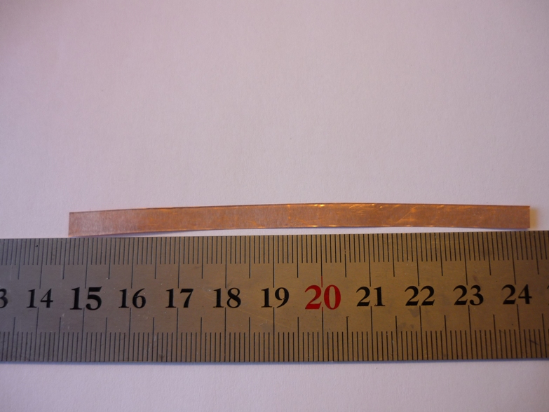
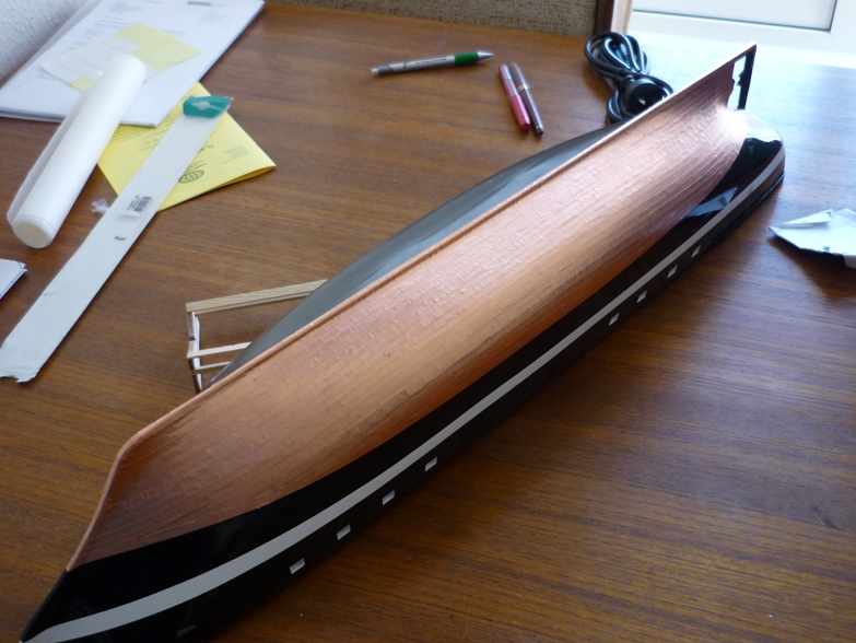
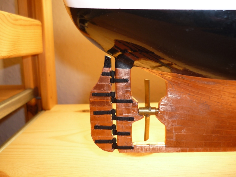
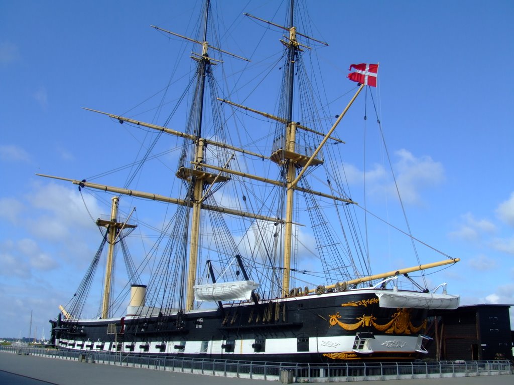
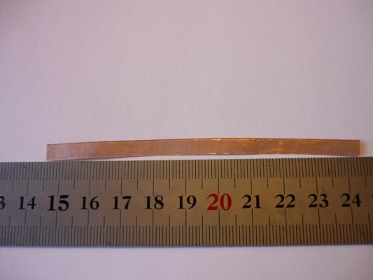
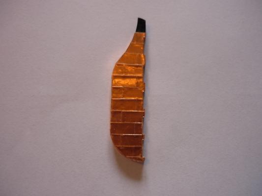
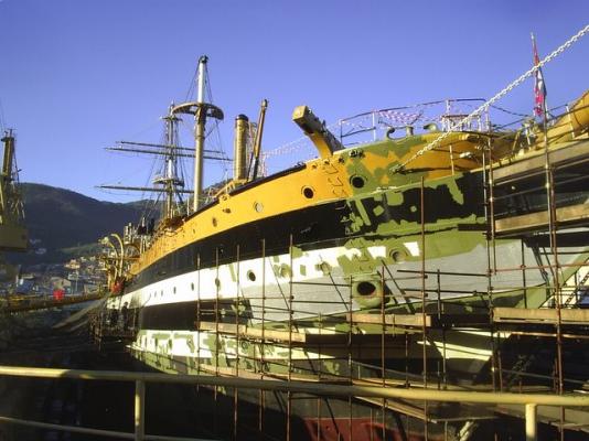
 Coppering I decided to cover the hull with copper plates instead of painting with copper paint. It adds a nice feature to the model but proved to be quite a challenge. First a photo of the real ship showing the original copper plating. I bought some copper sheets and intended to cut out the plates from this sheet. I used a rolling knife but it still resulted in warped strips even when cutting on a hard surface. Thus, attachment to the hull was quite difficult. I first tried gluing on the individual plates but it didn't work well as I managed to glue the plates to my fingers instead. So I cut out the strips and marked the individual plates on the strips. It worked better. I started with the keel then did the band of plates at the water line and then filled the gap between working my way from the keel and upwards. Here's the first side completed. Also, the rudder was coppered. The next photo shows the rudder attached to the hull. You may noticed that I've painted the hinges black. This was a mistake as pointed out by John (Jim Lad) and the hinges were painted with copper paint instead. It actually looked better too, I think. /Lars Peter
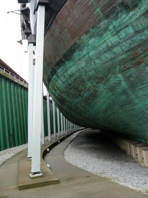


-
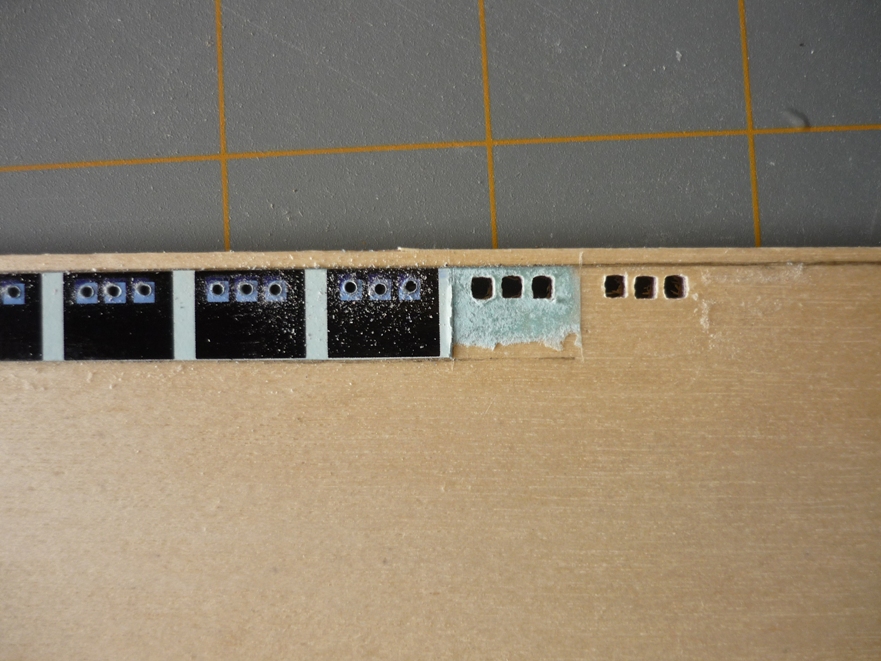
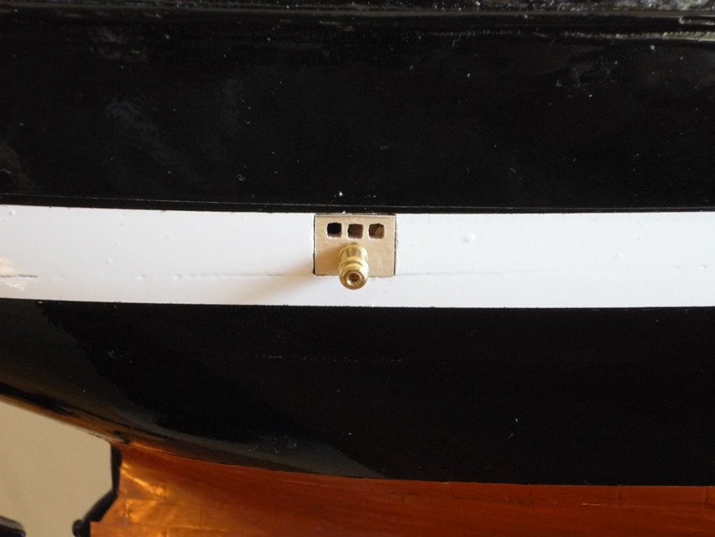
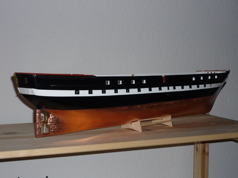
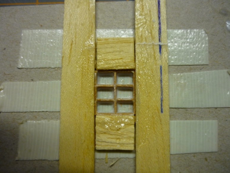
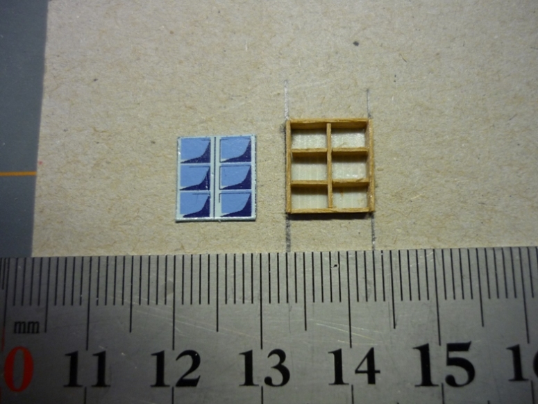
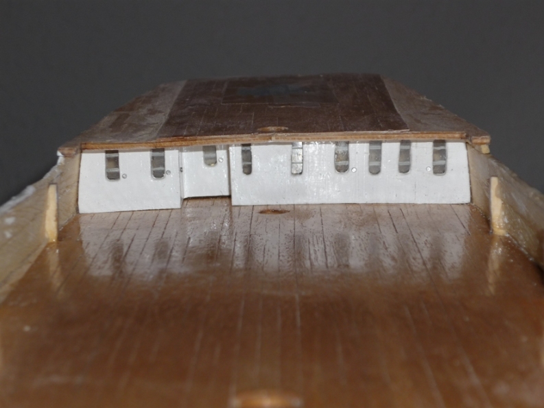
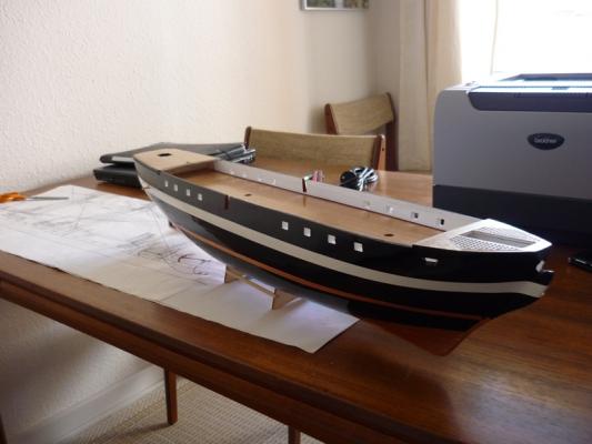
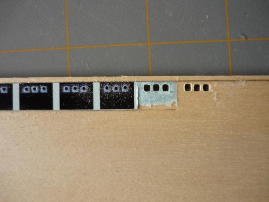
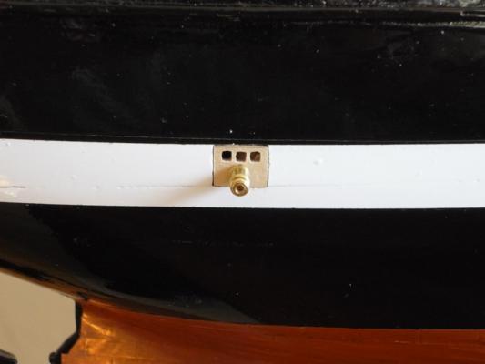
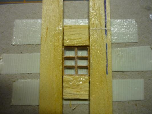
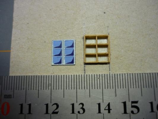
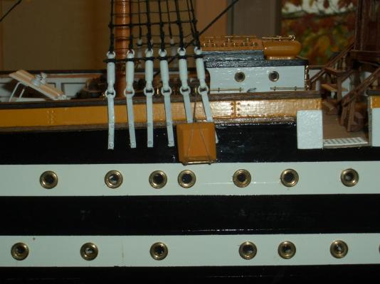
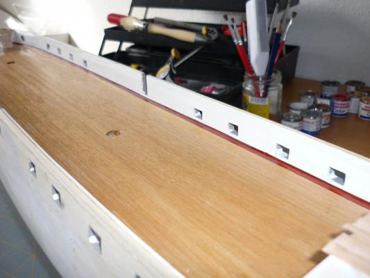
As you could see from the last picture in my previous post, the gun port openings had been cut and lined with wooden strips. They were later painted red. Brian mentioned that the lower gun ports were supplied as water decals which was also the case with my kit. I decided to cut the openings for the lower gun ports as well. In hindsight this should probably have been done prior to painting the hull. This photo shows the hull after paining. I used gloss paint which is properly not correct - I see people usually use matt paint for the hull. However, I think it looks ok. You will also notice that I've starting applying the coppering - more about this later. Lower gun ports. I made the gun ports out of plywood using the water decals as templates. The small windows were drilled out and squared with a needle file. On the real ship, the gun ports consists of two halves but I didn't want to go that route. There was more than enough work making these (30 in total). I bought some dummy gun barrels and holes were also drilled for these. Now came the scary part, cutting holes for the gun ports. I very carefully marked out the location of each port - drilled a number of holes and removed the waste with a knife. Finally, the holes were shaped to size using small files. I took my time doing this because it was very difficult to repair any damage to the paint work - gloss paint doesn't repaint well. The next photo shows the first gun port in place. Before gluing, the ports were painted, the windows glazed and the painted dummy barrel was glued in place to act as a convenient handle for gluing the port in place. Here is a photo of the first side done. I also decided to make the four stern windows instead of using the water decals. I used double sided tape to hold the pieces in place in a small jig. Then thinned glue was brushed on. When the glue was dry, the frames were cleaned up and glazing applied. I smeared some Vaseline on the jig to prevent the frame from sticking to the jig. Finally, holes were cut and the window frames glued in place. The photo looks a bit strange because the camera failed to capture the 3D structure of the stern. Next up coppering... /Lars Peter
-
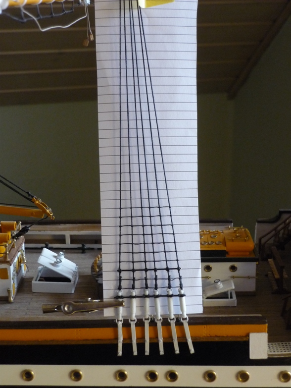
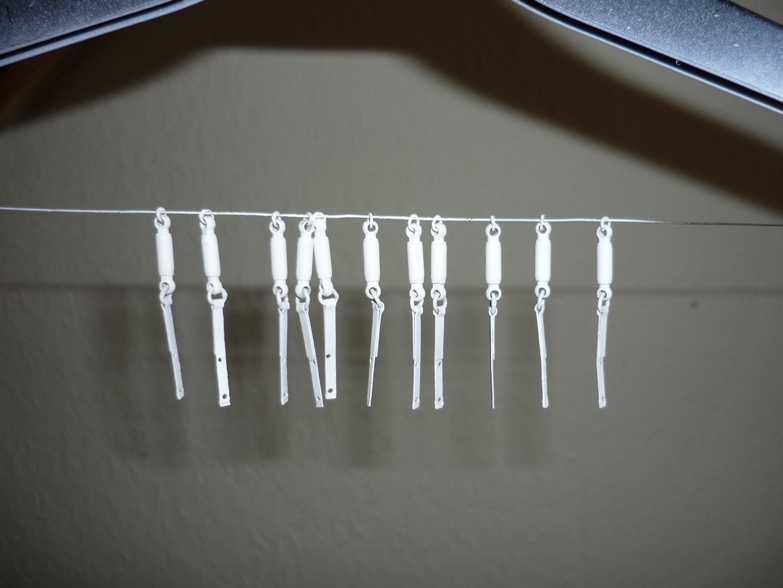
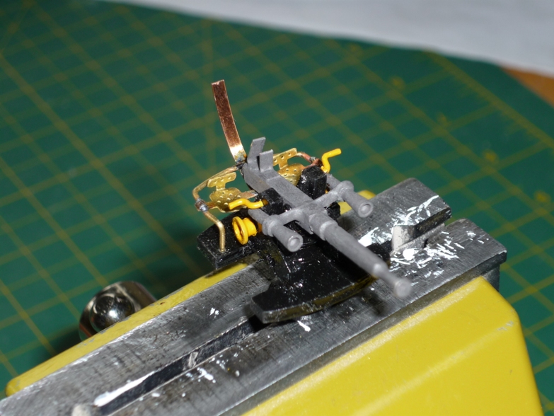
Thanks guys, it's great to do some fiddly work again after doing three of these (still have two in the order book): Five "turn-buckles soldered today - only 21 to go. /Lars Peter
-
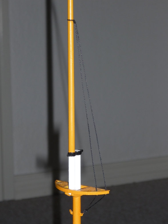
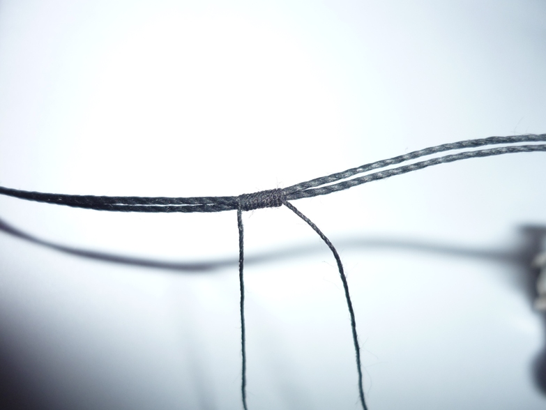
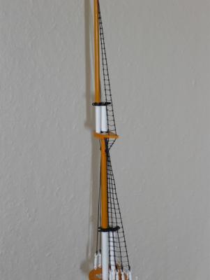
Hi All, Winter is approaching and it is time to turn my attention back to my AV - it has been neglected for far too long. After a lot of soldering I managed to get all the shrouds tied up. I have also installed to first of many life rafts. A piece of coiled rope will finish the job on the deck. The net job is to do all the back stays - 26 lines in total. This means back to soldering "turn-buckles". I start to hate these things! For each "turn-buckle" two rings need to be soldered to take the tension of the line. When this is done a brass strap is wrapped around one of the rings and then soldered - 78 places to apply solder. So see you again in a couple of weeks. If I get tired of soldering, I can always do some rat lines /Lars Peter
-
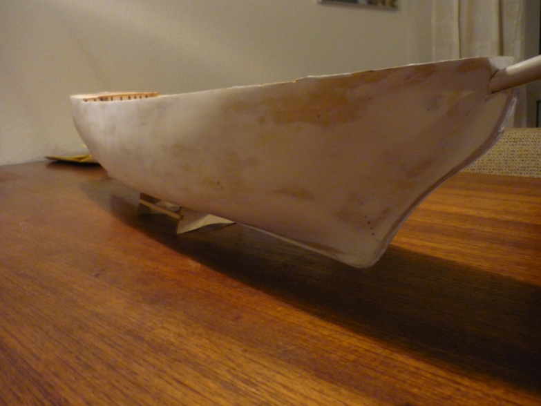
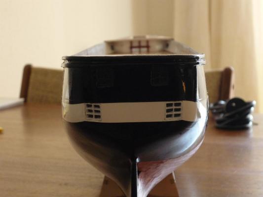
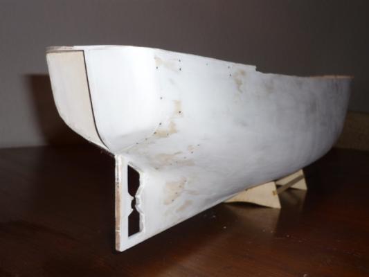
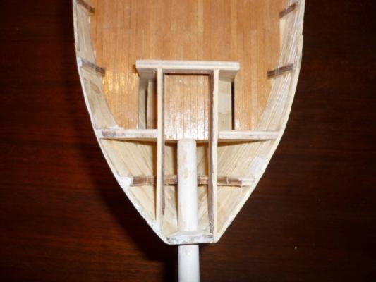
Planking complete As mentioned in my earlier post I do not have photos of the early stages of the build. The photos below show the hull after the planking was completed. Also, filler has been added and the hull has been sanded. The hull is single planked on frame using abachi strips - not the easiest wood to work with because of the very coarse grain. The stern was finished using balsa blocks. Here is the first one in place. Top view of the bow. The next photo shows the cabin panel in place. This was later replaced because I wasn't happy with it. Also the main deck has been planked. The main deck was also modified. The outermost planks were ripped off and replaced with red planks. More to come. /Lars Peter


-
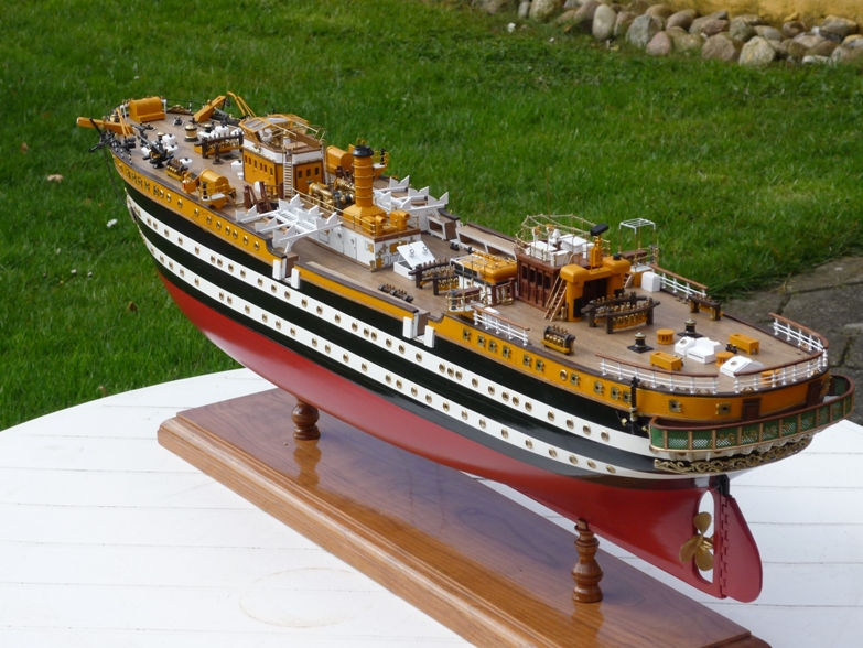
The real ship Several ships have been named Jylland (Jutland in English) but the Frigate Jylland is the last to have this name. It was completed in 1860 as the world's last srew-propelled frigate build entirely of wood. During the 1864 war it saw naval action against the Austrian-Prussian fleet at the battle of Helgoland where it sustained considerable damage. In the 1890s the ship was reduced to stationary use and barely escaped scrapping in 1908. It was, however, decided to preserve her and she was towed to Ebeltoft in 1960. The hulked frigate further deteriorated until she was placed in dry dock in 1984. Restoration proved to be a major task; over 60% of the timber had to be replaced in addition to the rigging, armament, engines and loose gear. Some of the above is taken from Wikipedia and it is not entirely correct. The steam engines was scrapped in 1892 but I have heard, the museeum is planning to build an replica. Jylland is today sitting in dry dock due to a warped keel. It is located in Ebeltoft, Denmark and is open for vistors. The restauration work continues. Some figures Jylland had a crew of 430 men. It had 44 cannons and is today known as the world's longest war ship build entirely of wood. Length: 71 meters Width: 13 meters Depth: 6 meters Displacement: 2456 tonnes I have some detail photos of the ship which can be found here: https://plus.google.com/photos/107544960066597140114/albums/5388856511393884641 Also, I have downloaded a 33 pages document expalining in details how the ship was build and it's history until today. Unfortunately it is in Danish but I plan to translate it for you all to see. It is quite interesting. The BB kit The kit for building the Frigate Jylland is made by Billing Boats. Some of you are familiar with the quality of BB kits (or should I say lack thereof). You can build a resonable model directly from the box if you favour lots of plastic parts, water decals for gun ports etc. I did some modifications to the kit and added (will add) details that are not part of the kit. Also, I did a few changes to the rigging as the kit drawings was wrong in a few places. The plans and instruction require a bit of imagination at times as it is not always clear how things are supposed to be made or look like. I'm definately not and expert in model building and I have made numerous mistakes along the way. I remember some of them and will explain as I re-create the log. Unfortunately, I do not have the photos from the early stages of the build so we'' start off after the planking was complete. I hope you'll have fun watching this log.. again for some of you. /Lars Peter

-
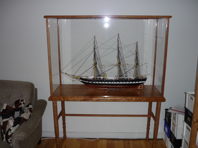
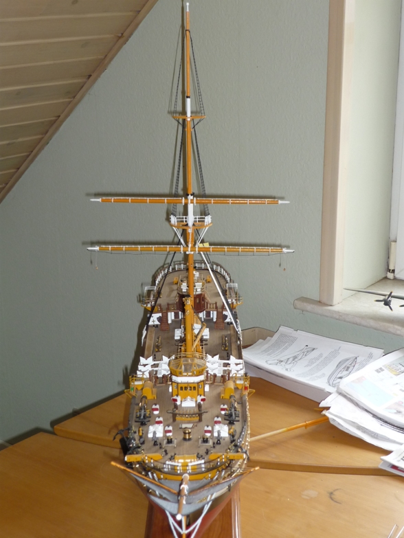
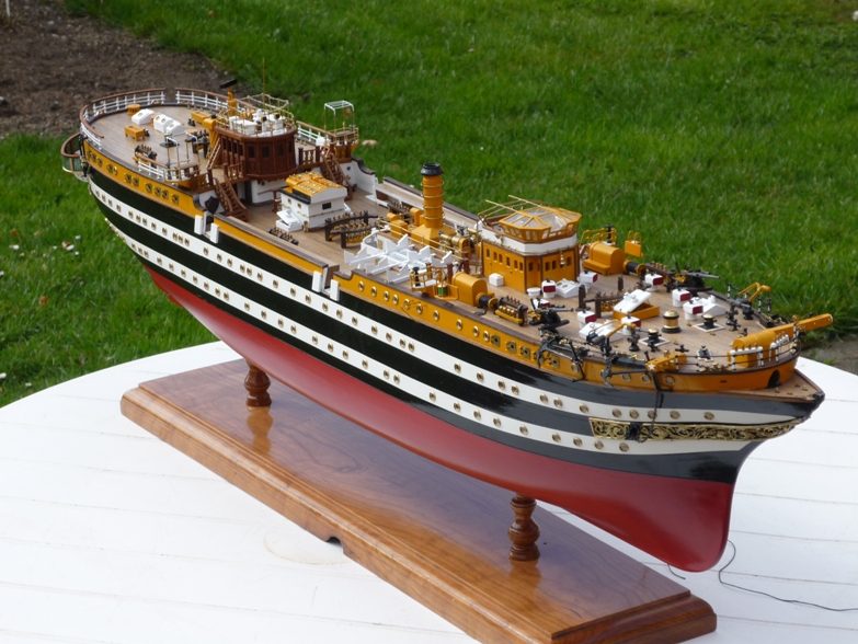
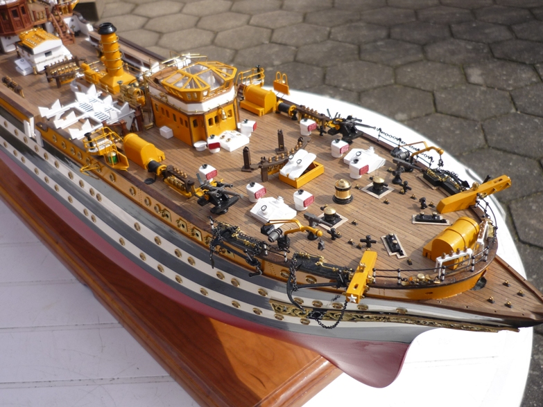
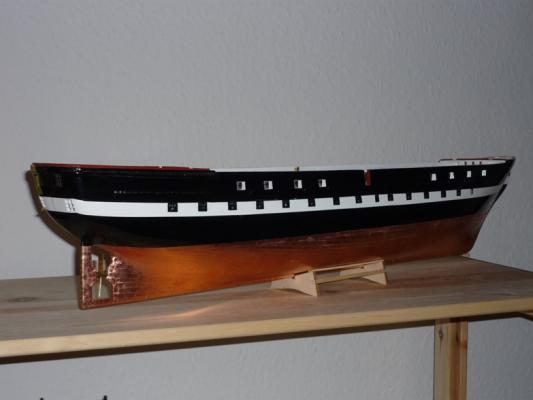
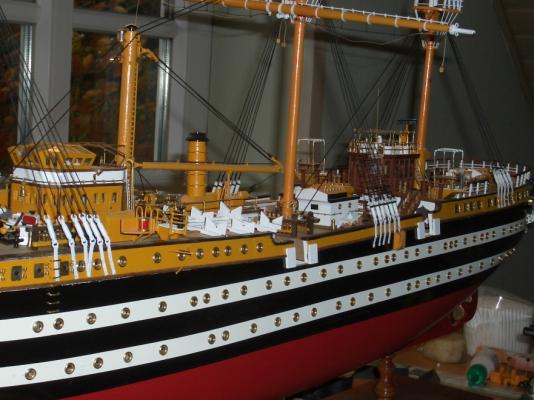
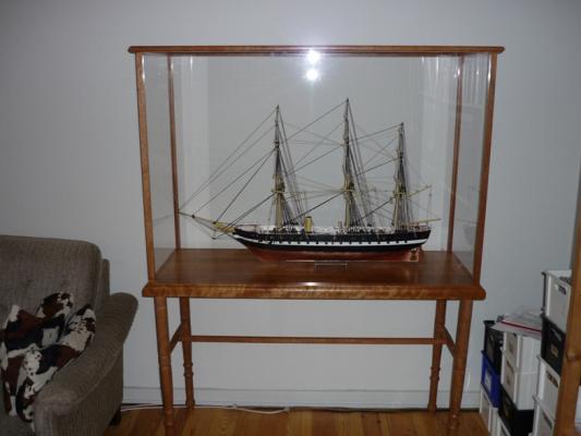
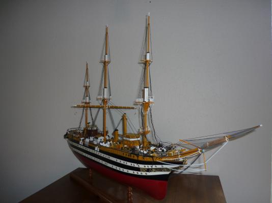
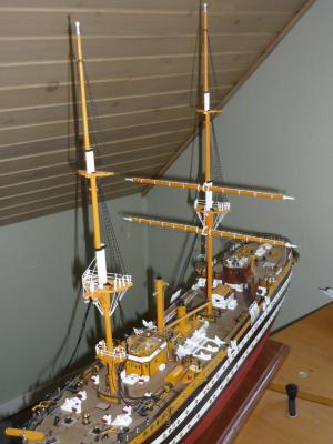
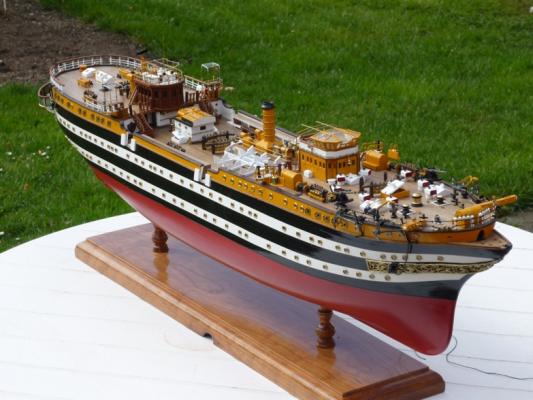
Hi All, After a few request I have decided to recreate my build log of BB Frigate Jylland. I have most of the photos from the log on my PC but unfortunately not the writing and discussions contained in the old blog. It's been a while since build the model (and it is still not complete) so I'll do my best writing down what I remembered - especially where I deviated from the plans and did a few modifications. I will just ask you to be patient with me. It is rather tedious work (and not the most interesting to re-create and entire build log) but I'll do my best to hurry up. As a teaser we should end up with somethings like this: /Lars Peter
-
Hi Richard Thank you for your comments. Unfortunately, I haven't had time for modelling lately - too much gardening and maintanence work outside during summer. Regarding soldering of the conning tower, it was a real pain. The angles were not a problem. They are given by the laser cut parts and if you start from the bottom up, it should be ok. The problem was holding the peices together while soldering (is used my third hand here) and avoid unsoldering previously soldered joints again. After soldering everything was filed down and any gaps filled with epoxy filler before final sanding and paining. I mainly did this because it didn't fit the deck house when I used the clear plastic moulding. /Lars Peter
-
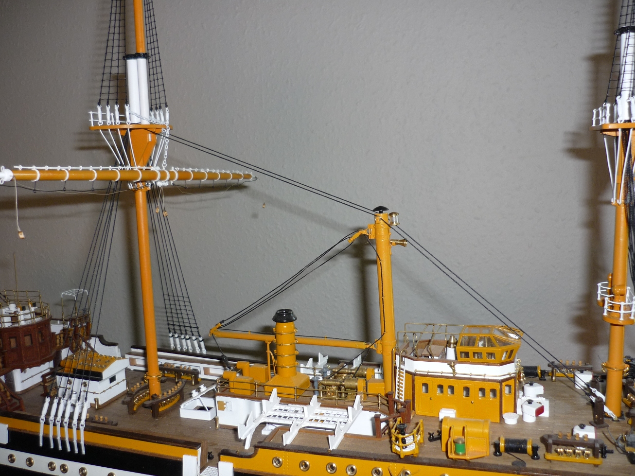
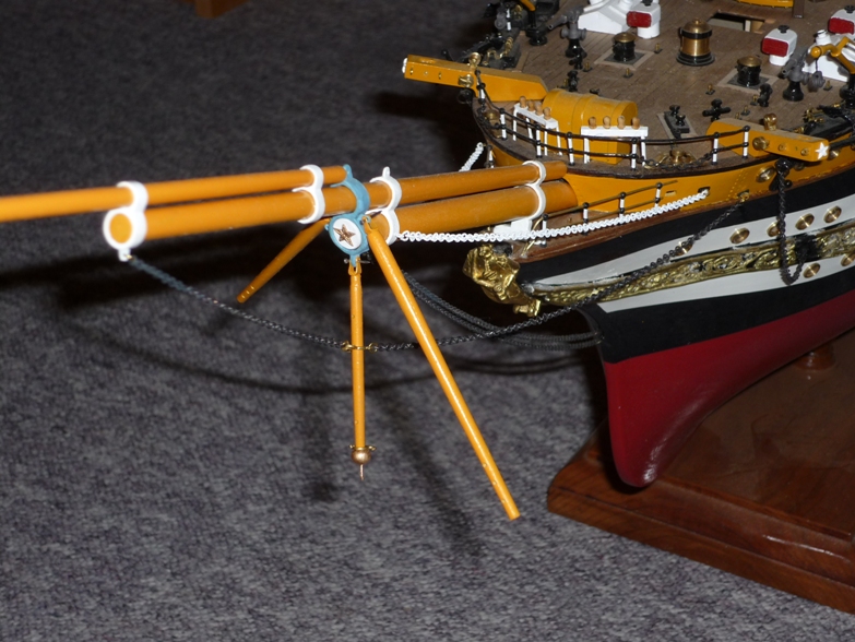
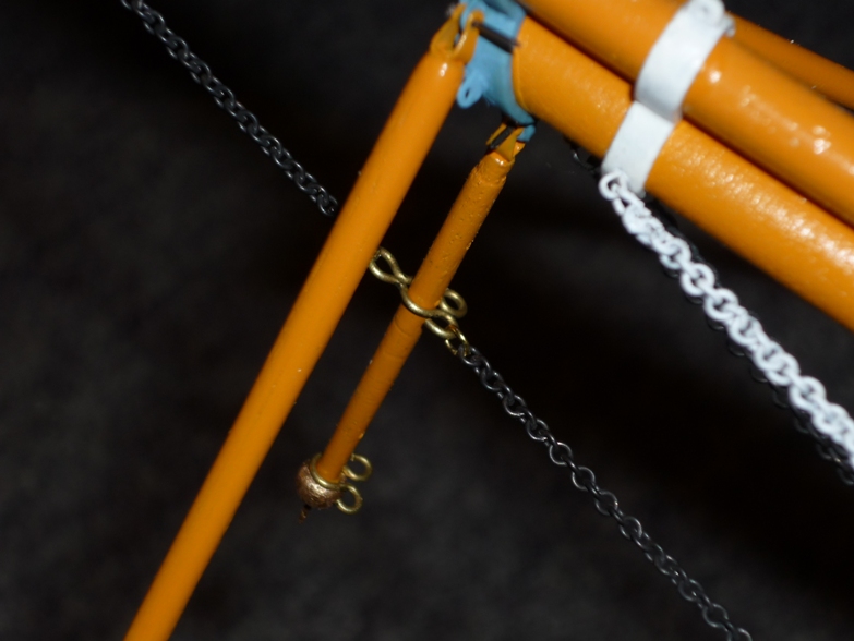
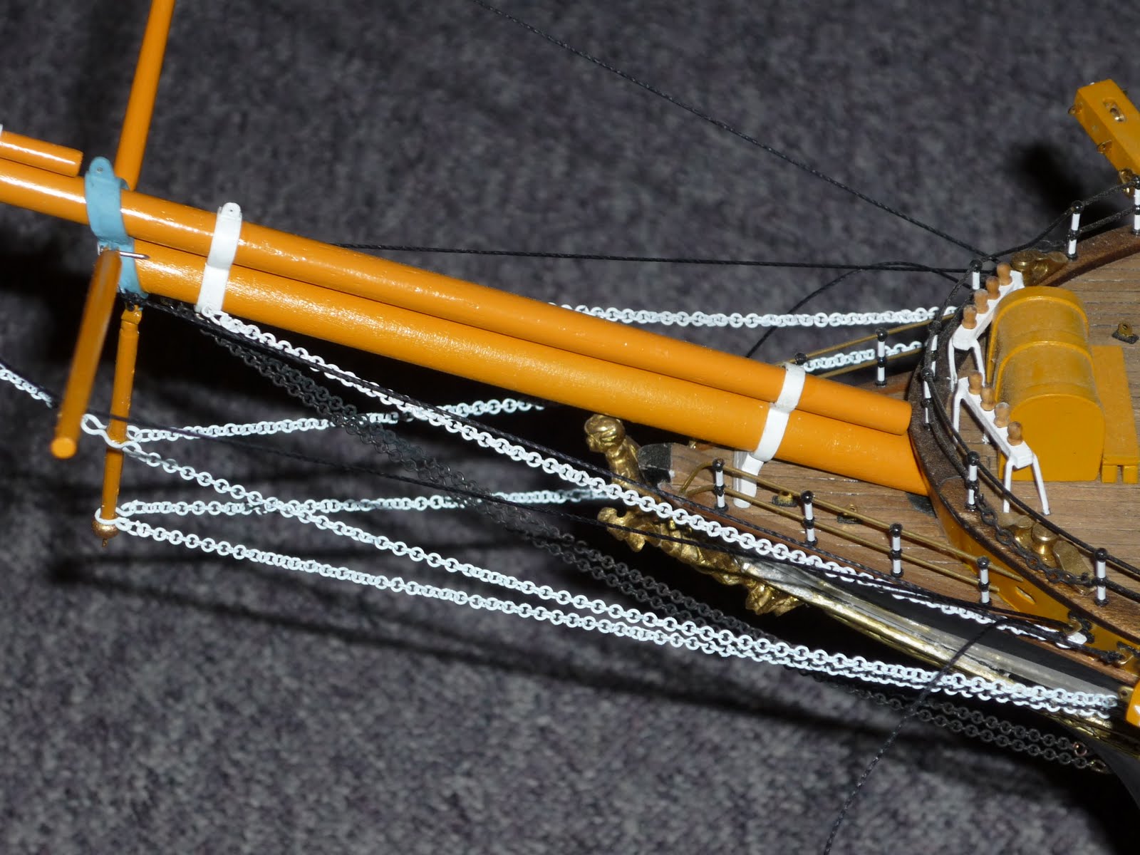
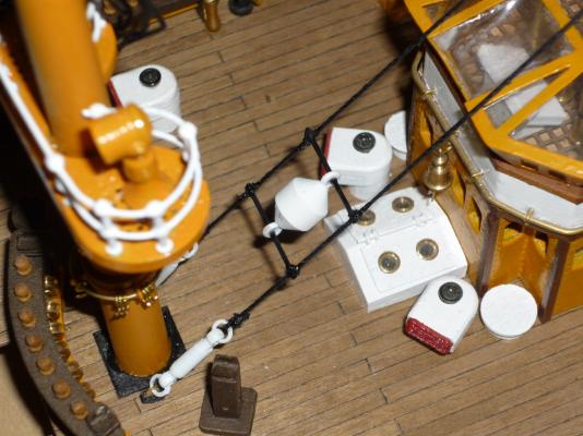
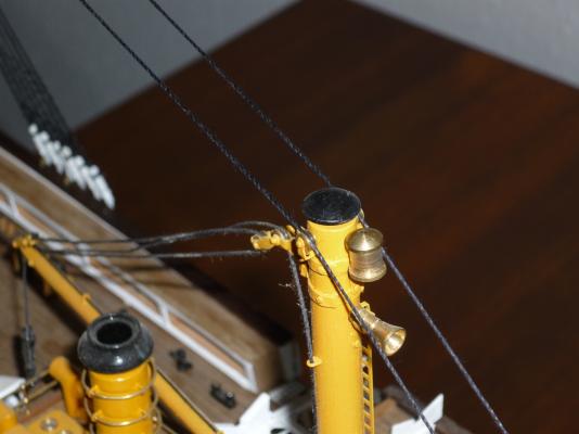
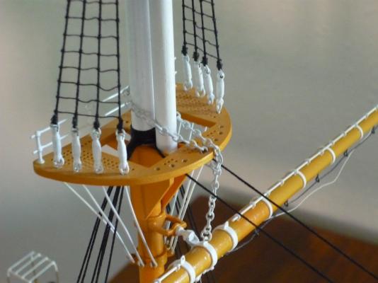
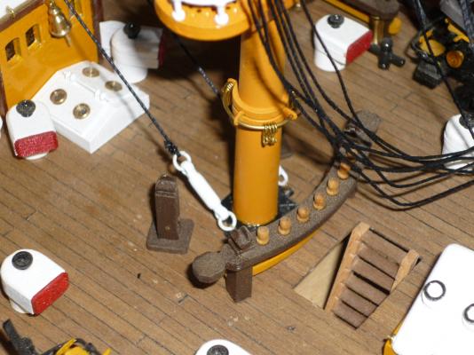
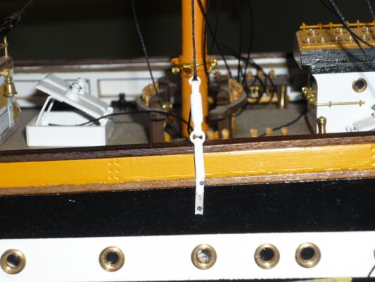
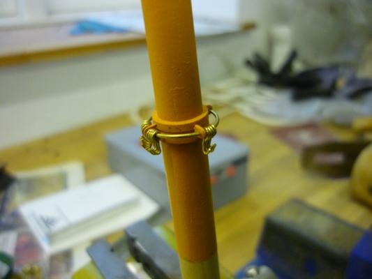
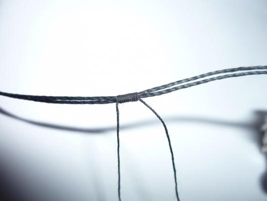
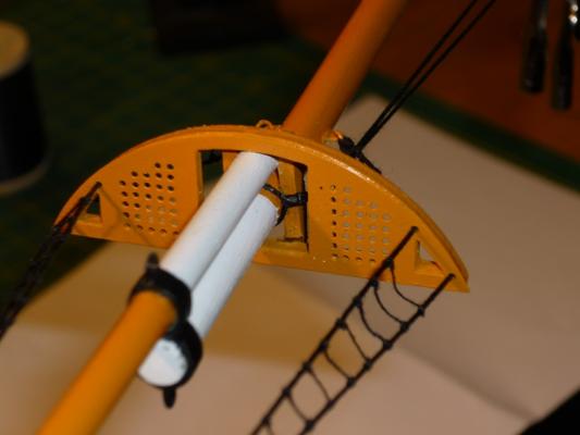
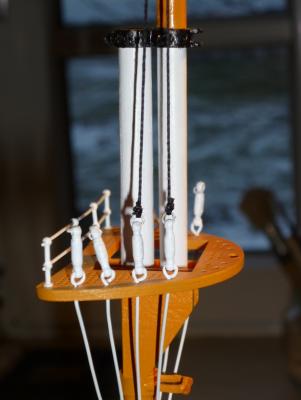
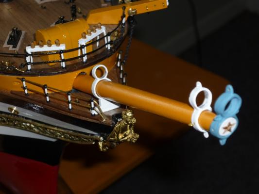
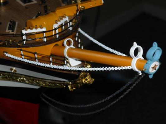
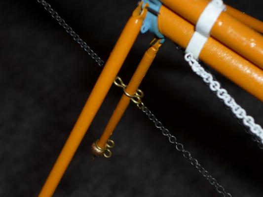
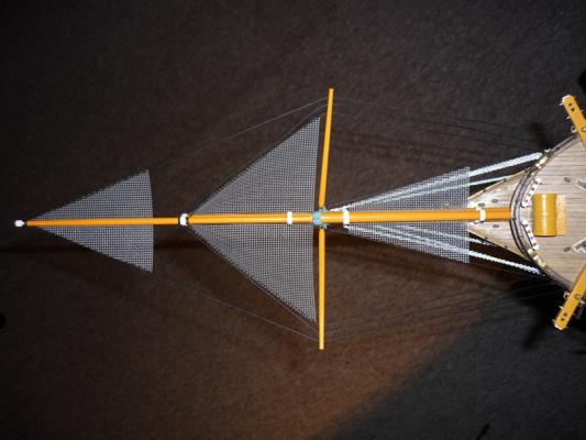
The mizzen and fore stay have also been attached now. Here is the mizzen stay. The fore stay proved a bit of a challenge. I've made mistake of gluing the eye bolt on the platform in place before I fixed the bowsprit in place. I tried to attach the rings and turnbuckles but there simply wasn't enough room to use the plieres. Also, that would have left the rings unsoldered - not a wise things as quite a bit of tension is put on the stays. Instead, I pryed off the eyebolt. They were fixed quite wellso I destroyed two in the process. After this it was straight forward to attach the fore stay. The fore topmast stay is another challenge because it will go around a pair of sheaves fixed to the bowsprit, through the netting which doesn't leave much room for tying the knots and then down to a pair of eyebolts on the platform. The last photo shows a thingy attahed to the main stay. Can anyone tell me what this is and what the function may be? /Lars Peter

-
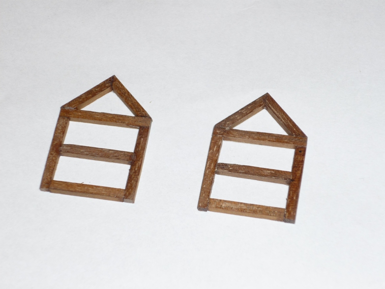
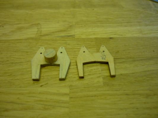
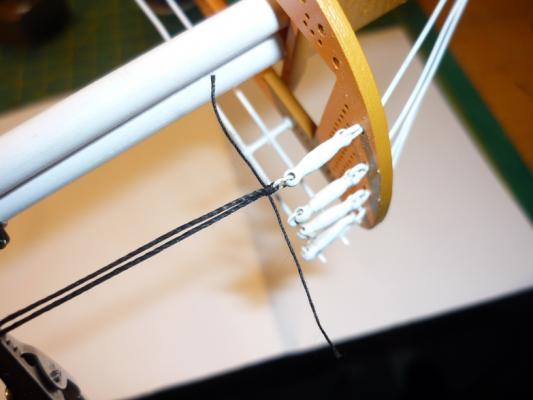
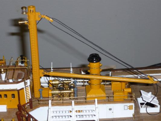
Thnak you John for your advice regarding the gaff. I have discarded the laser cut jaws supplied with the kit. They were way too big so I have carved a new pair that fits better around the mast. I will make a post regarding this later. In the meantime the mizzen mast has been finished and glued in place. I guess this is a major milestone to have all three masts in place. I have also attached the first pair of stays (the main stays). These were easy to fit to the deck because I haven't attached the fore shrouds yet. It may be a bit more difficult with mizzen stay bacause the main shrouds are already attached. To clear the deck house the stays rest on the crane. I will have to add a drop of glue here because the stays push the crane a bit aft and loosens the hoisting cable. Here is the attachment of the stays to the main mast. The other end of the stays are secured to the deck next to the fore mast. The brass rings were soldered prior to paining to make sure that they could take the strain when tighting the stays. Many more stays and shrouds to attach :-) /Lars Peter

-
I got an excellent link from Joachim (thanks again) with a belaying plan for AV. It ahouls prove useful when I get deeper into the rigging phase (running rigging). Regarding the gaff boom, Joachim also send be an excellent photo of how the gaff boom attaches to the mast. Judging from the photo it seems like the kit is more or less correct (see previous photo from instruction booklet). However, the kit instructions does not mention the throat halyard anywhere. Only, the peak halyard is shown. There, should be room for a small improvement here, adding the throat halyard. However, I'm missing information regarding the belaying point for this. I assume it would be belayed somewhere on the fife rail - but which belaying pin. It seems like most of the belaying point are for the sail rigging. I will not add sails on my model - so hopefully there will be some free belaying pins. Do I just choose one somewhere close to the middle? I will add the throat halyard before I glue the mizzen mast into place . easier that way. /Lars Peter
-
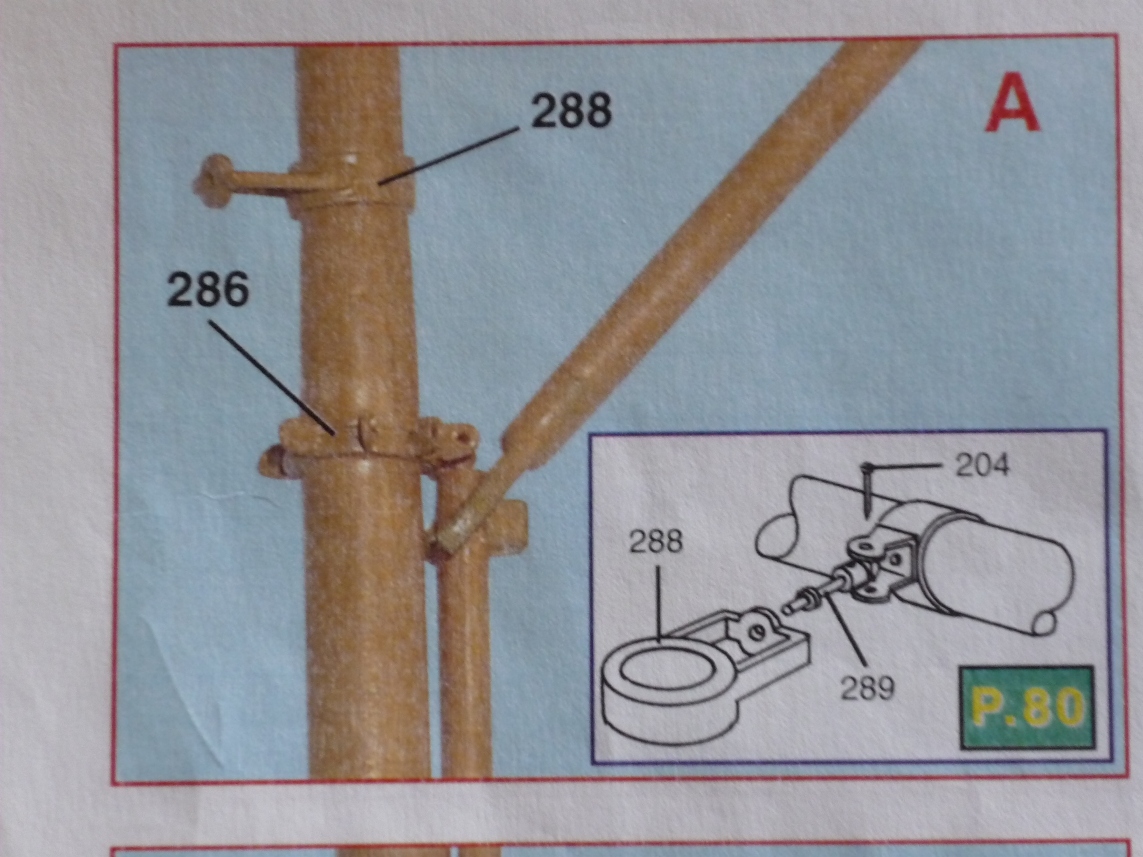
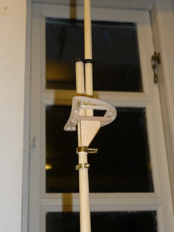
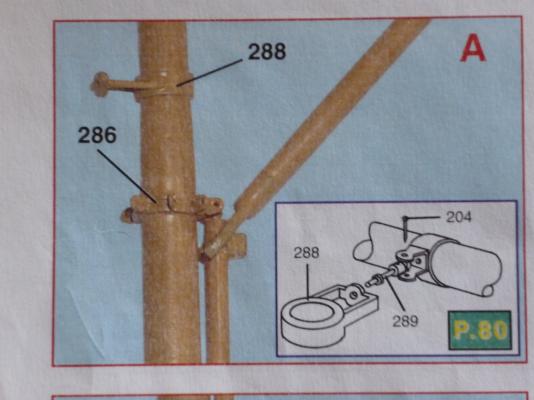
I have a question for you guys. I'm almost ready to install the mizzen mast but before I do so, I have to think about how to attach the top boom to the mast. As you can see from the instruction photo it is not shown how to secure the boom to the mast. There is not enough room to use the usual pearls on a string method. So what do you think? Should I just drill a couple of holes in the fork and then secure the boom with a piece of string. I have not been able to find information about how this is done on the real ship. /Lars Peter
-
Thank you for your kind comments - even though my AV fades a bit compared to Joachim's masterpiece. I more or less stick with the kit content and just try to correct the errors I discover. Nontheless, another major task has been accomplished - the foremast is complete and glued into place. The bottom shrouds will have to wait being attached until I find some suitable nails. I have some brass nails but the head is rounded and too big. The work continues on the mizzen mast - at least there are fewer ratlines on this on ;-) /Lars Peter

-
Hi Joachim Magnificent work on the stairs - they look really good. I have one question though. Looking at photos of the real ship you're right that there are only three stairs for entering the main deck (no stairs for the foremost starboard entry way.) Do you have any idea what this entry way is used for then? I'm have looked much into building the stairs myself yet. Want to fit them after the rigging is done so I don't accidently knock the off. Does the kit show three or four stairs being fitted? I found this photo on this entry way being used (at least I think it is the right one) while the ship was being repaired. Perhaps it is only used for dockside entrance. /Lars Peter
-
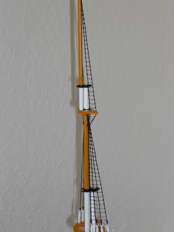
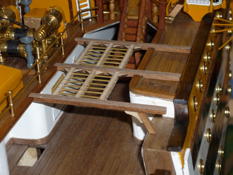
The rigging of my AV continues to frustrate me because of the poor instructions. Basically, it comes down to study the photos in the instructions booklets and try to figure out what's going on. The problem here is that the photos seem to have been taken during various stages of the construction so it is really difficult to know what's right and wrong. Details of the yards are only provided for the mizzen mast. Judging from the photos the yards for the main mast seem to be slightly different regarding the various fittings. I have almost completed the second yard for the main mast but decided to stop that for now. It will be easy to figure out how many eyelets, blocks etc. that will go on each mast if I build them together with the work on the running rigging later on. So it is basically back to doing shrouds and ratlines. All the main shrouds have been tied in place and I have started doing the ratlines. Looking at photos of the real AV, it seems like iron bars have replaced every fifth ratline. I will not do that but have fitted only the two bottom bars. I thought it would be a good idea to finish the fore and mizzen mast so these can be put in place. You may recall that I had to remove the topmast shrouds on all the mast to replace the turnbuckles for smaller ones. So I have started redoing these on the foremast. So more shrouds and ratlines. Once the fore mast has been glued in place, I will continue with the mizzen mast and and the standing rigging before work continues on the yards and running rigging far into the future. /Lars Peter

-
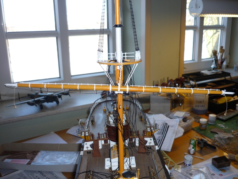
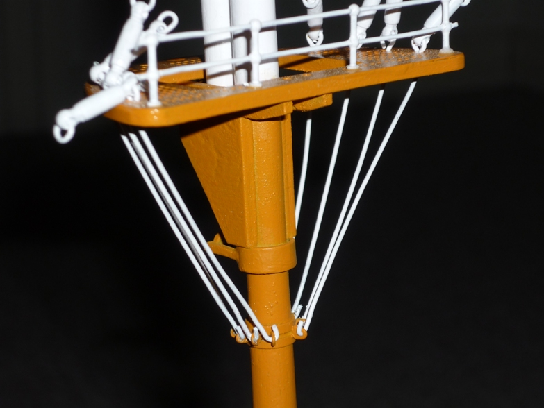
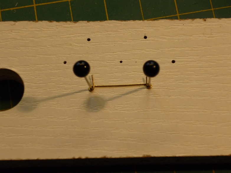
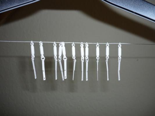
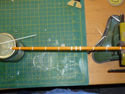
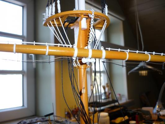
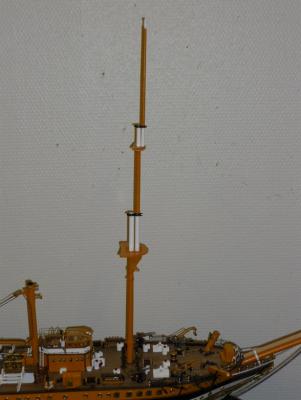
New update - main mast The main mast is complete and has now been glued in place with epoxy. I have done all the metal work for tying the shrouds. These consist of a turn-buckle, two rings and a brass strap - all soldered. Finally, they were painted white. I simplified the paint job in contrast to the real ship. Here is the first strap glued and pinned in place on the hull. The instructions do not mention anything about the distance between the shrouds so I use the photos from the instructions as a guide. I have ordered some more nails for fastening the remaining straps as my brass nails are too big. Main yard The main yard (330 mm) is finished at glued in place and secured with a chain. All yards follow the same principle of construction: Tapering and shaping the ends on the lathe. Then the ochre paint is applied before the rings are glued in place. The kit supplies the rings as laser cut ply wood. I would have liked to use these but the laser cutting is done very poorly so you end up with a V-shaped cut. They are very thin so it is impossible to sand the inside to achieve a straight edge. Instead I made the rings from plastic strips glued around the yards with CA. This can only be done after painting and is very difficult. The ochre paint is acrylic and not very strong so sometime it peals of. Even after re-painting these spots it is not possible to achieve a nice paint finish. After the rings have been installed I put masking tape on each side of the rings, sand them smooth and fill any gaps before applying a coat of white. It looks decent now (at least from a distance). Applying rings to second yard Some photos of the main yard in place There are five yards on each mast so this is going to take a while. /Lars Peter

-
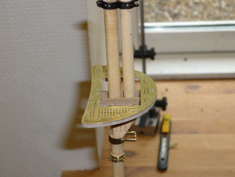
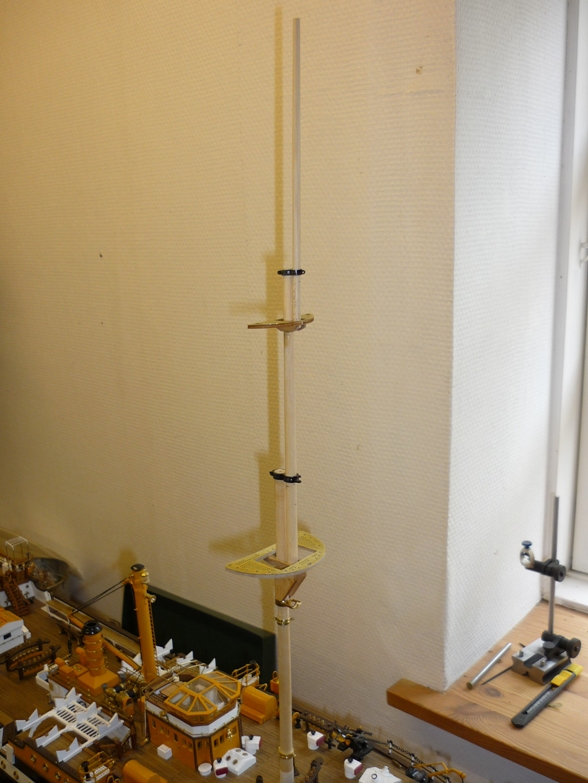
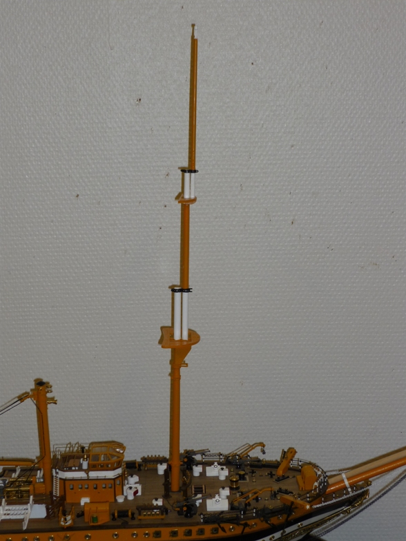
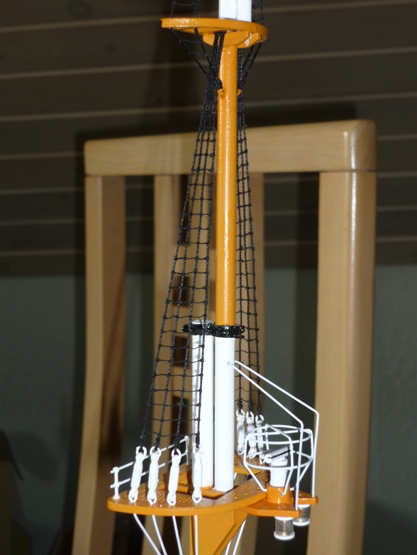
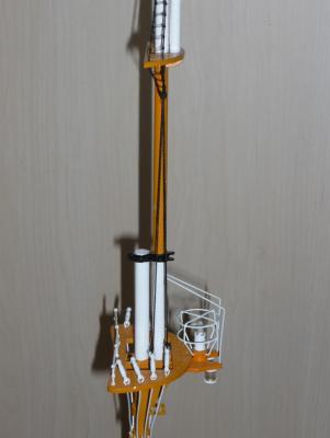
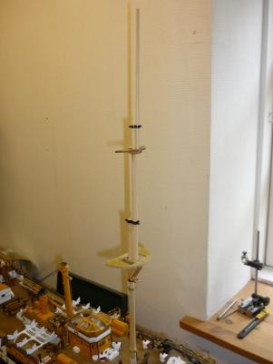
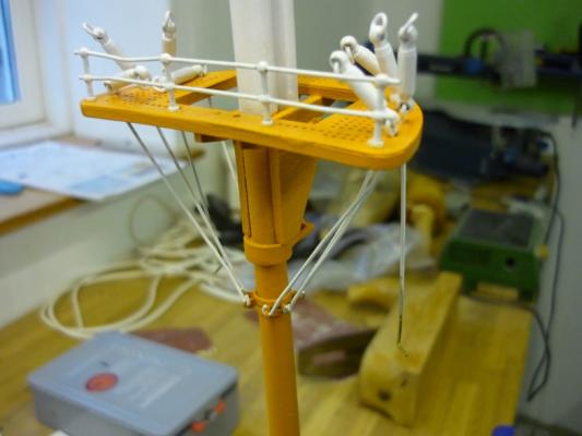
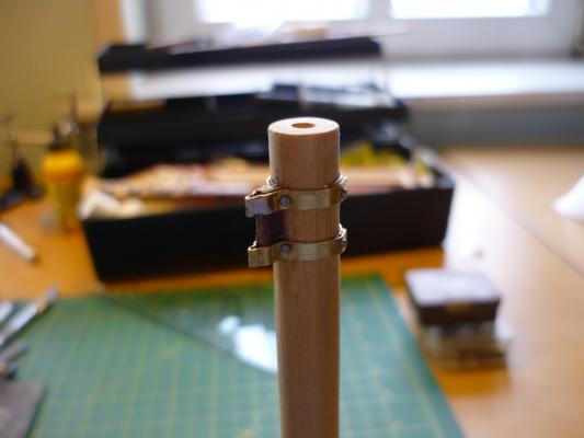
Construction of masts Foremast The mast platforms were all cut out from plywood and glued to the photo etched platform tops. I had to do this because the laser cut kit supplied pieces didn't fit the photo etched pieces. Fore mast dry assembled Fore mast painted Adding futtock straps I later realized (after I finished these on all three masts) that I used the wrong size turn-buckles. This meant that I had to strip some of the shroud rigging and replace them with the correct size. So far I have done this on the main mast. Fore mast details Had to make a new piece here as well because the kit supplied piece didn't fit. Replacement of turn-buckles /Lars Peter


-
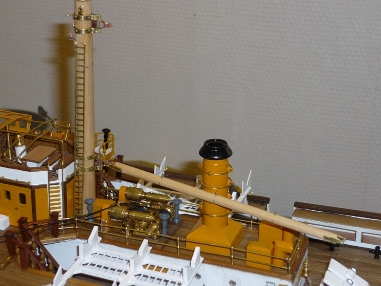
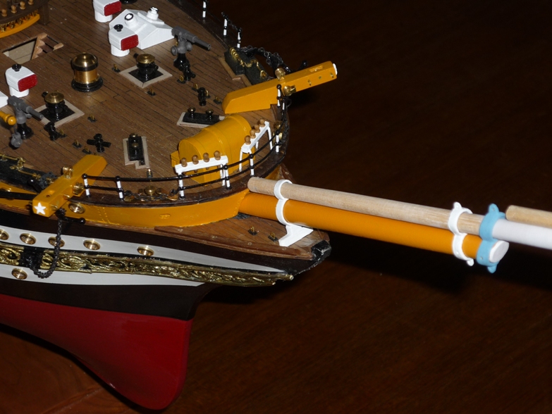
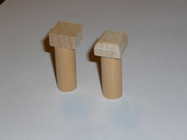
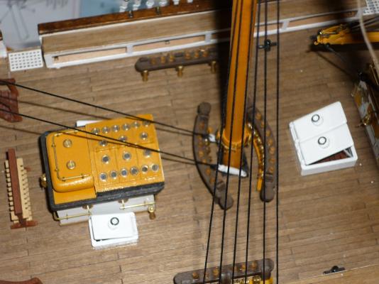
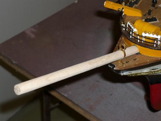
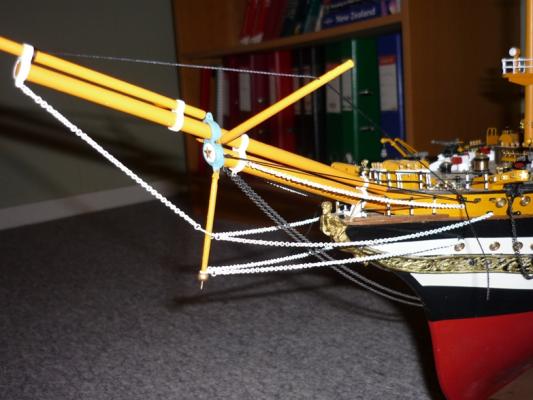
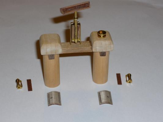
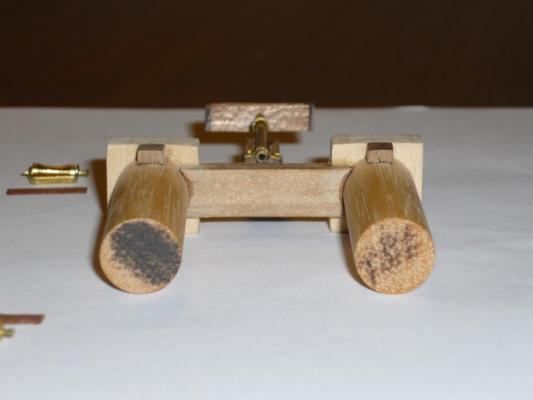
Thank you for your kind comments guys. I'm almost done with the re-construction of my build log. I have done quite a bit since the crash. The main mast is completed and glued into place. I have done the first spar for the main mast and is working on number two. It is all time consuming work as I have to wait for glue and paint to dry quite often. But first we need to finish the update of the old log. Construction of crane Bowsprit /Lars Peter


-
Hi Joachim I like the way you are making your model more authentic looking - big job. You're approaching the rigging job quite fast - big job I can tell you and not much help from the instructions. /Lars Peter
-
Hi Joachim Found your log today. I must say, you are doing a splendid job - like the way you bashed the small boats. I do not have access to any drawings so I will mostly follow the instruction - at least where they don't show mistakes. If my AV is going to look half as good as yours, I'm very satisfied. I'm currently well under way doing the rigging - doing yards at the moments. Keep those pictures coming. /Lars Peter
-
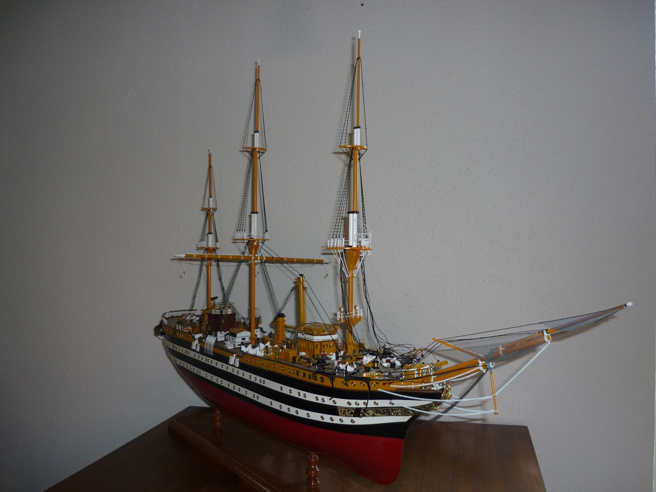
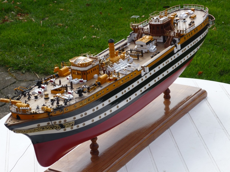
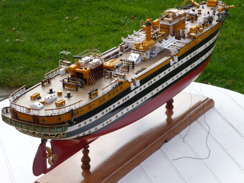
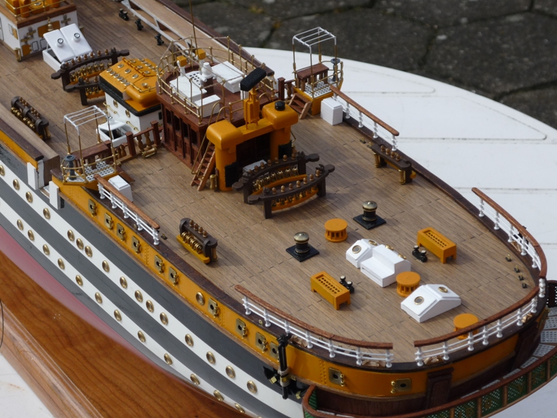
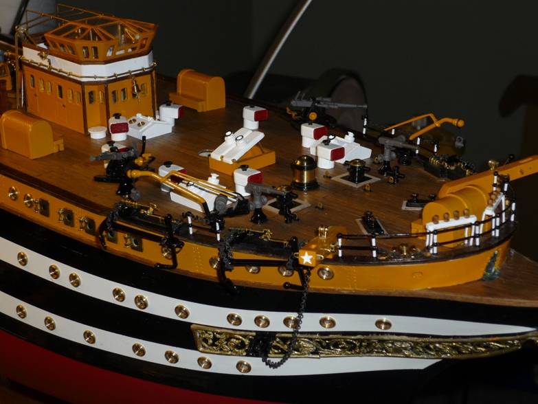
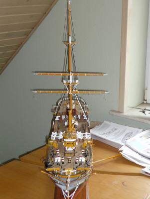
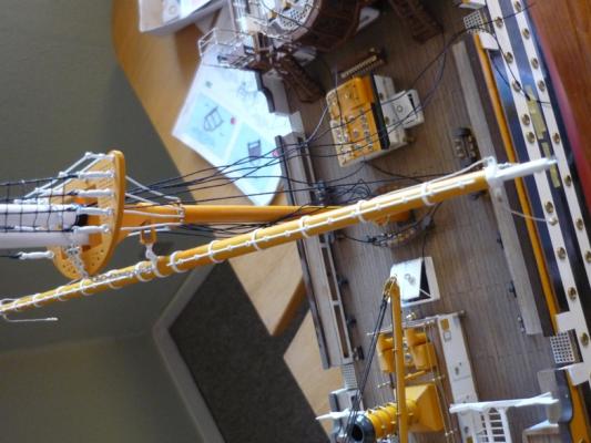
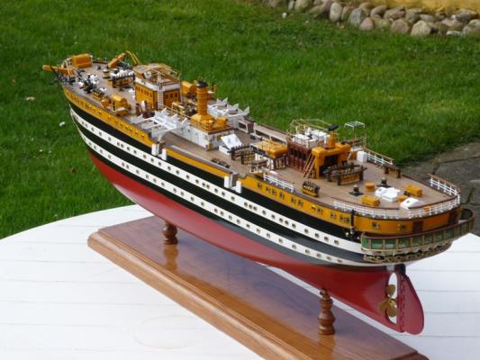
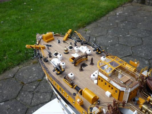
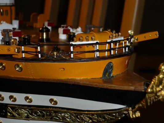
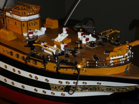
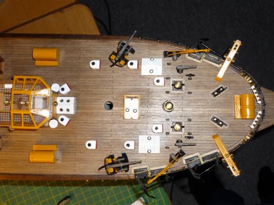
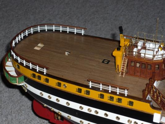
Last summer (2012) I took my AV outside for some photos to take advantage of the natural light. /Lars Peter


-
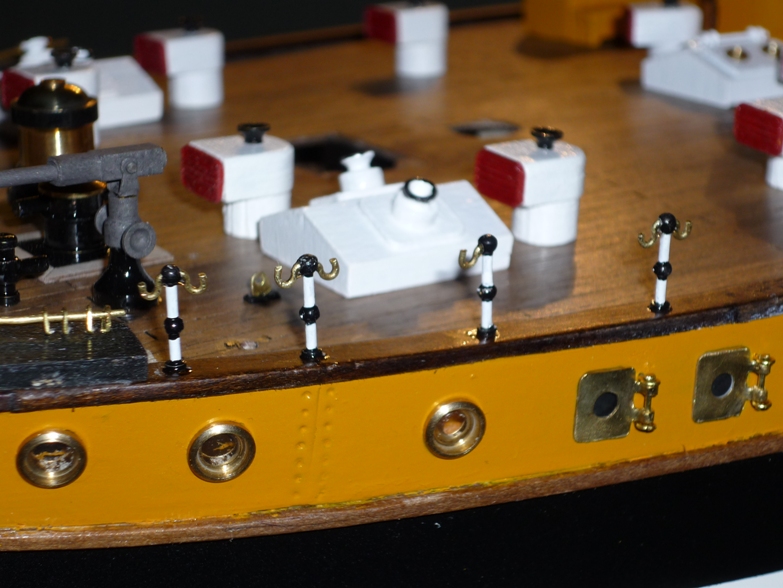
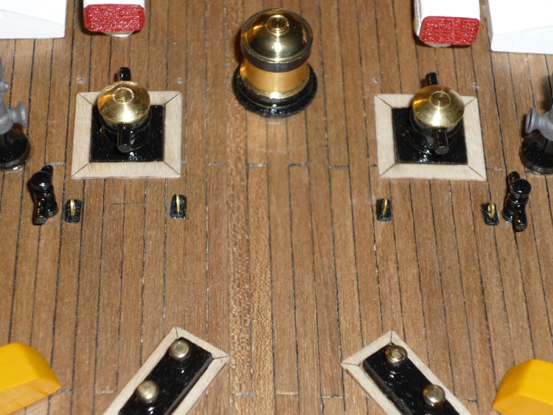
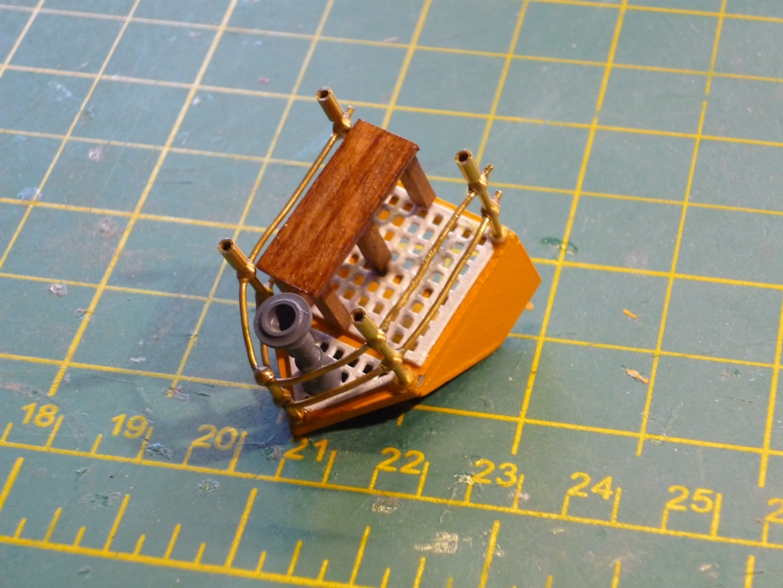
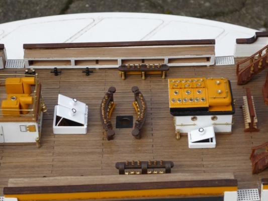
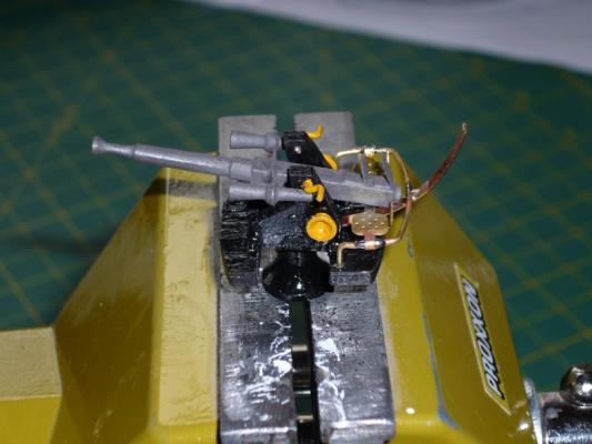
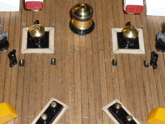
Various bit and pieces AA-gun Other stuff /Lars Peter


-
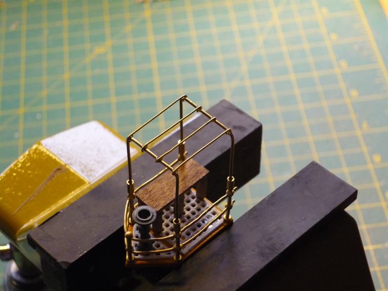
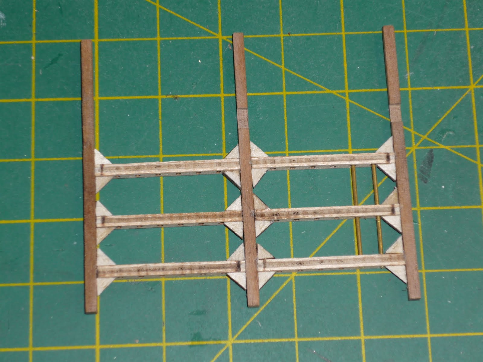
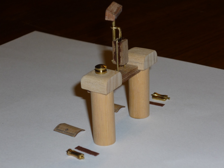
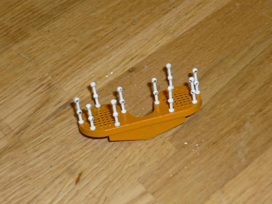
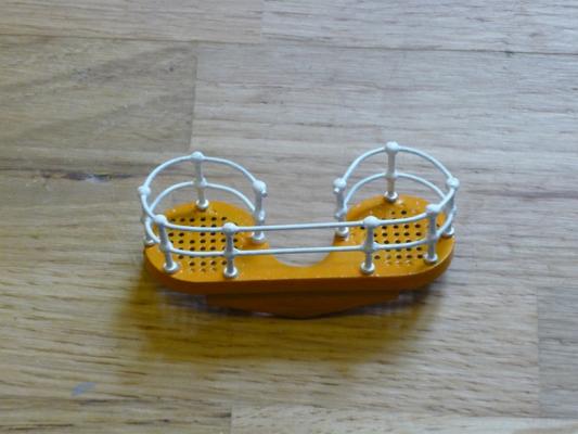
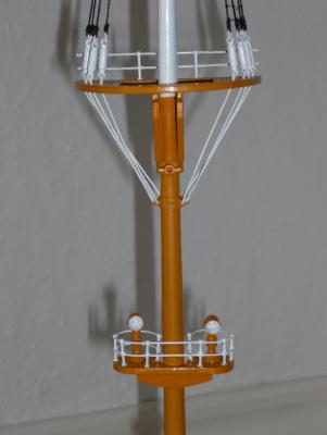
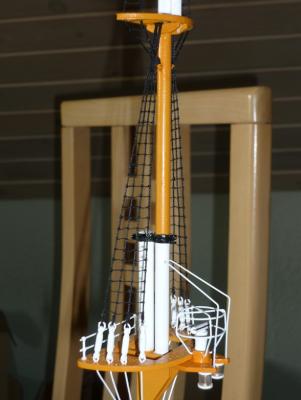
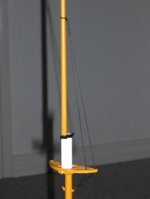
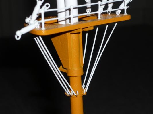
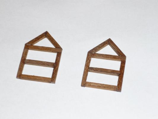
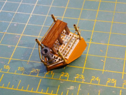
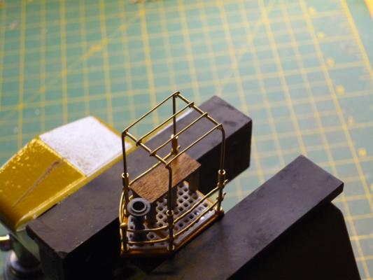
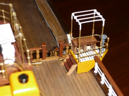
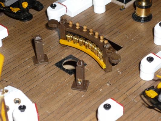
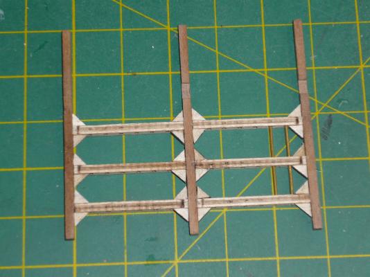
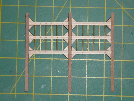
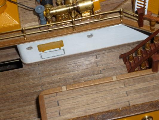
Radar The following photos document the construction of the radar which goes behind the deck house on the quarter deck. Fun piece to make. /Lars Peter


-
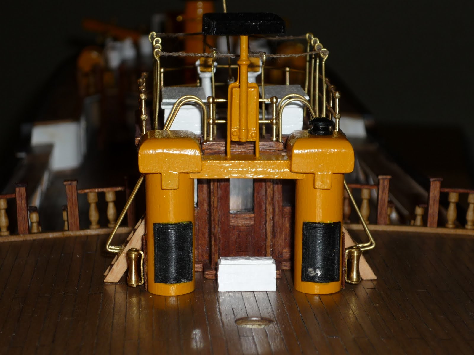
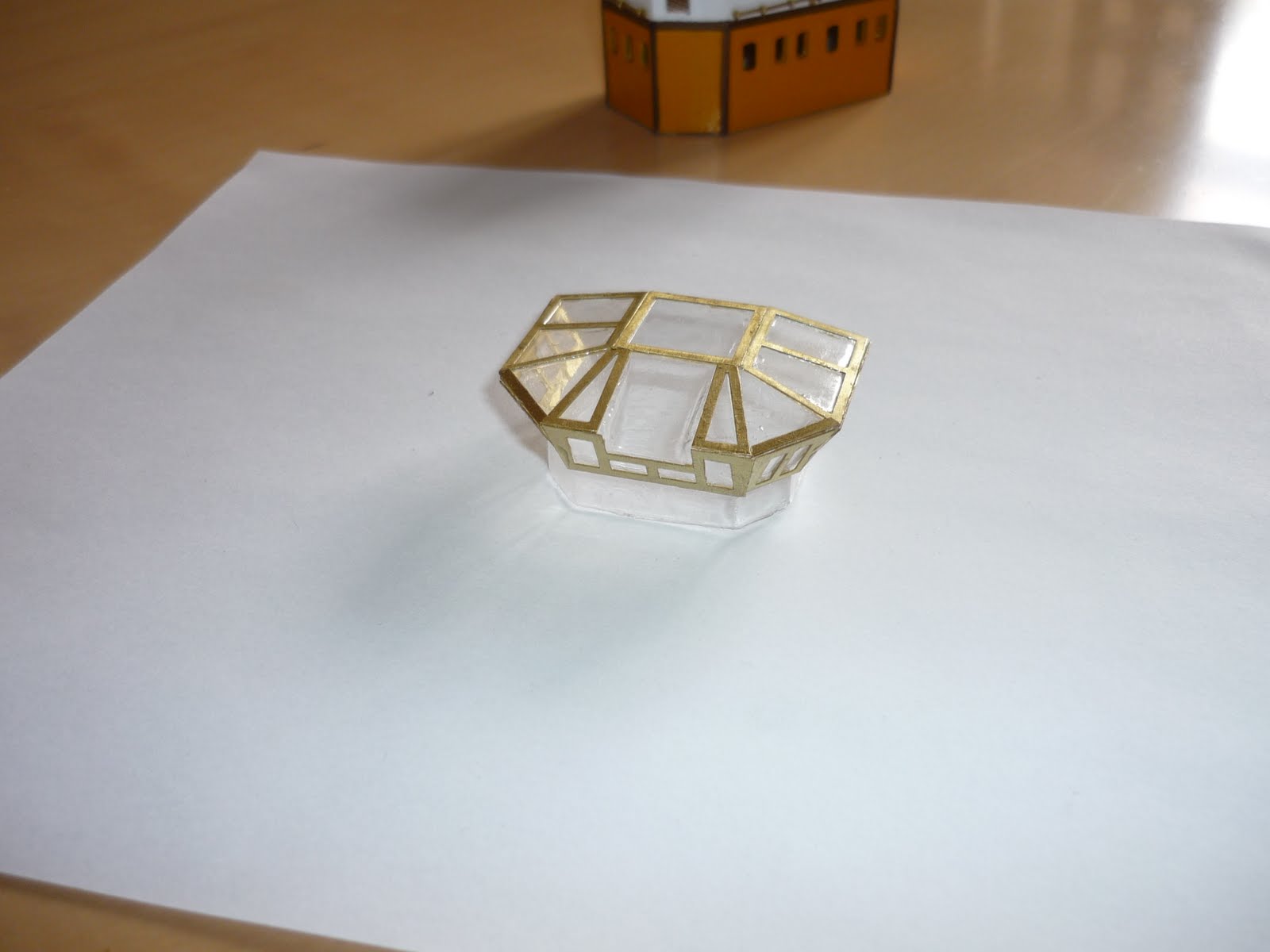
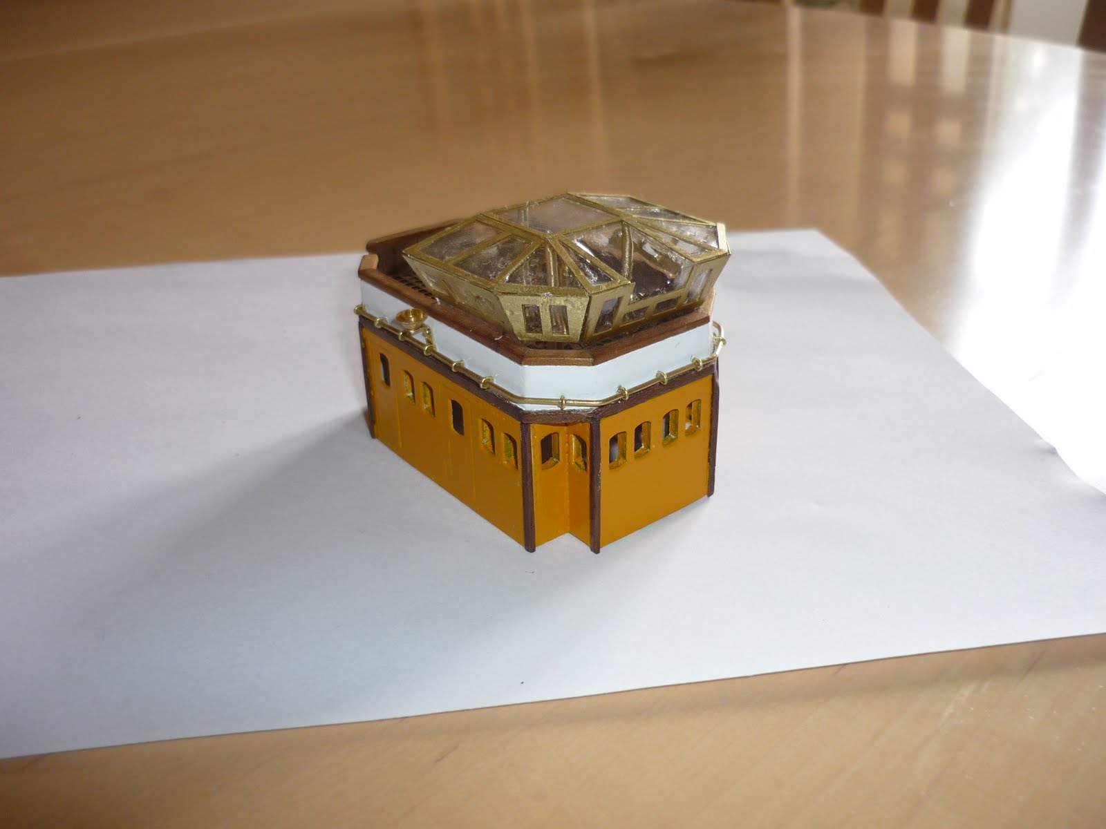
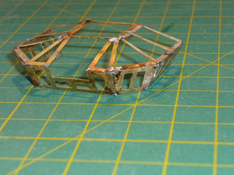
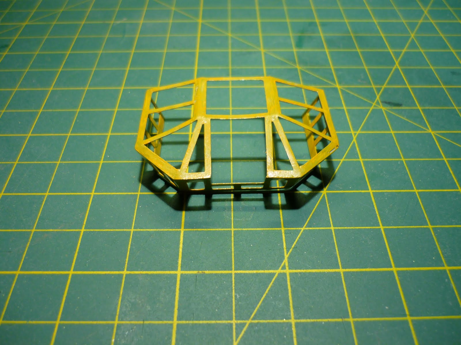
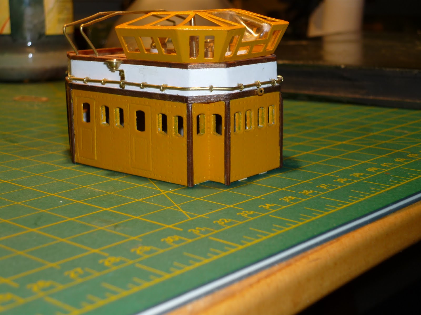
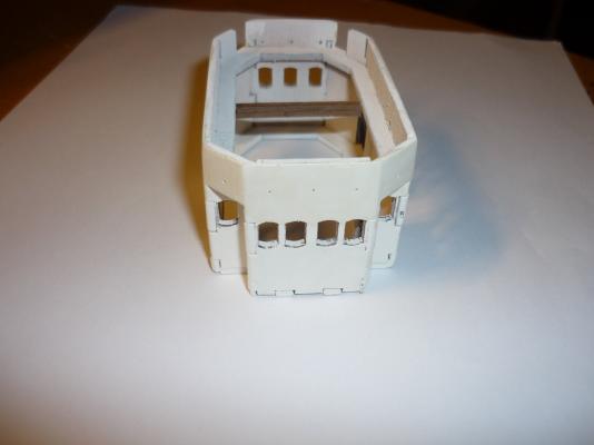
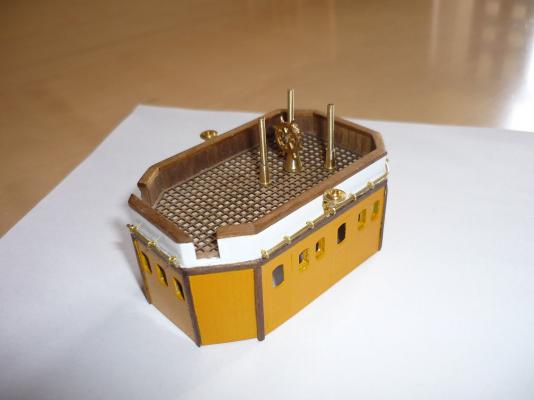
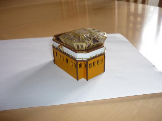
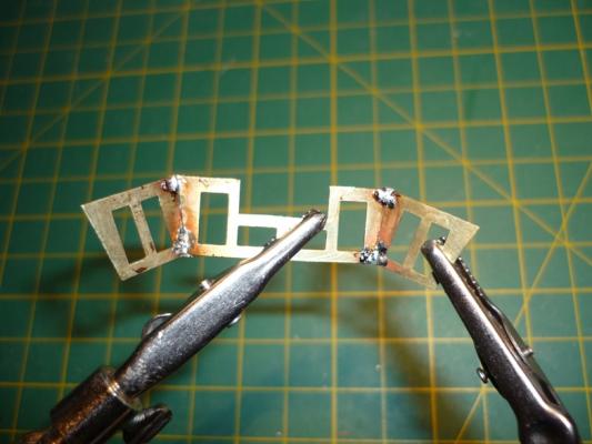
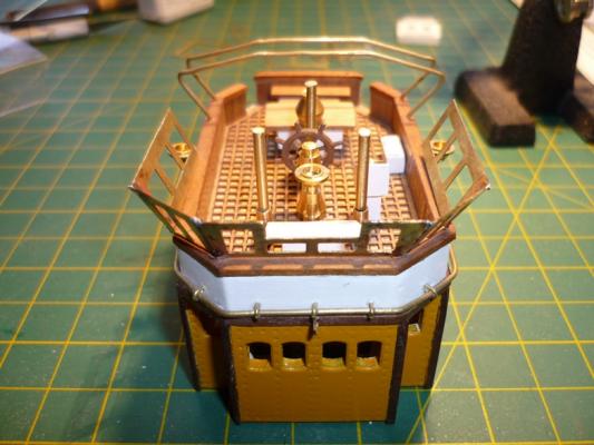
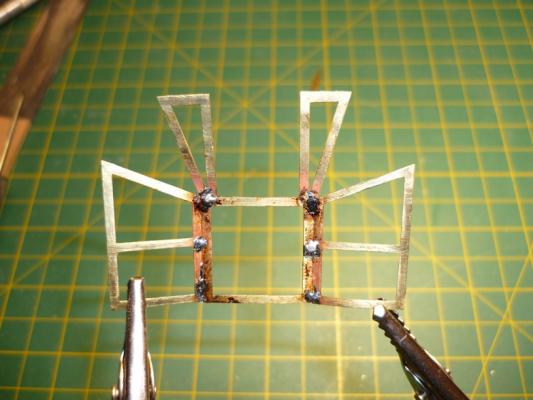
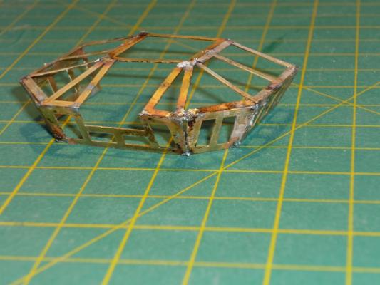
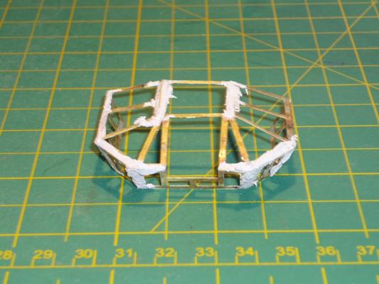
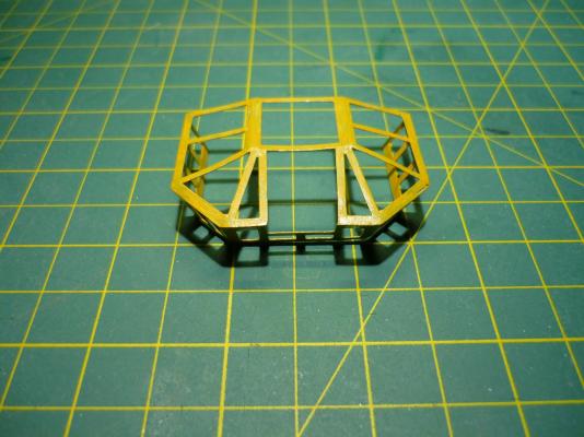
Deck houses II The last deck house which goes on the fore deck proved to be the greatest challenge so far with this build. Basic framwork Outer walls added and painted The wheel house roof is made up from a moulded piece of acrylic. The photo etched window frames are then glued on the moulded piece. However, as you can see from the next photo it did not fit very well. When I was packing things to move to my new house I accidental dropped the deck house on the floor and all the photo etched pieces was flying in all direction. Much later I decided to reconstruct the roof to make a better fit. I discarded to moulding - only re-used the slanted piece in the middle. I then decided to try out my soldering skills to make the window framing and then add glazing later. This was to put it mildly a pain in **** to make. Basically, when to solder two peices together to other pices came apart because of the heating. However, in the end I managed to solder everything to create one piece. It fitted much better. More soldering. And at last the framing was complete. Any gaps were filled with car body filler which is very hard and easy to sand. After sanding and painting it did not look too bad. Glazing was put in and the roof was glued to the deck house. Here the deck house in glued in place on the foredeck together with more stuff. /Lars Peter


-
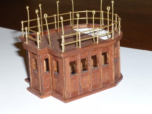
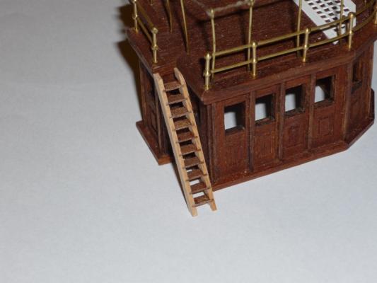
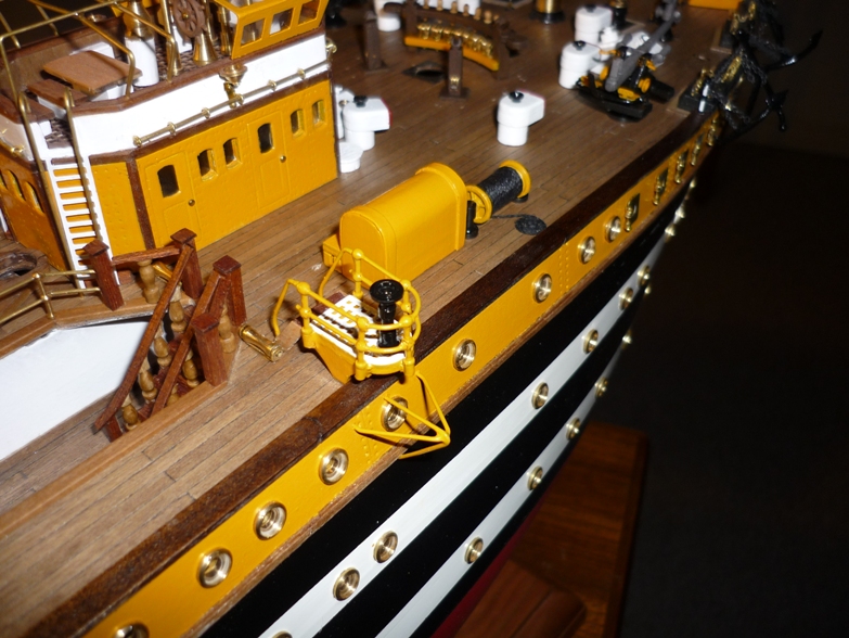
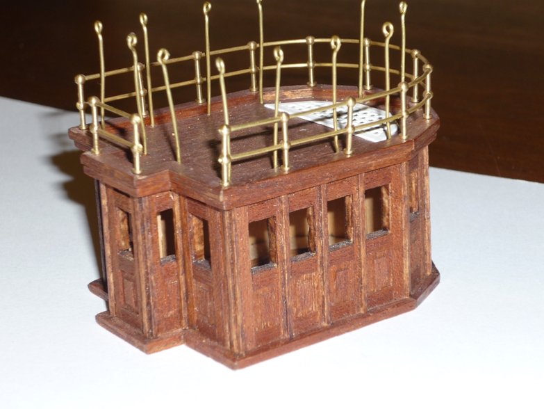
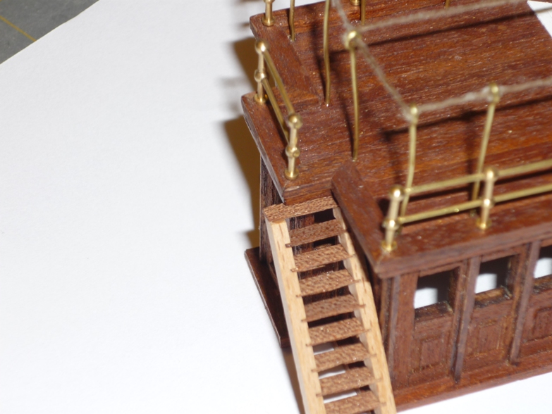
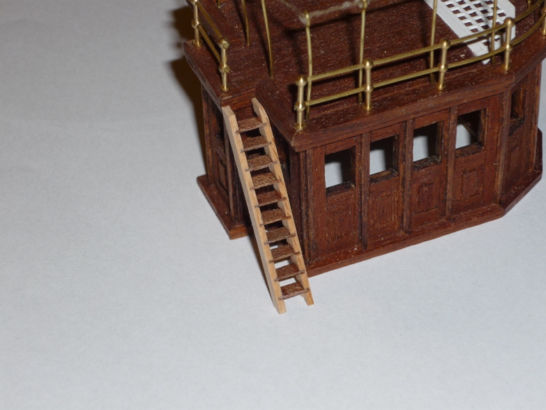
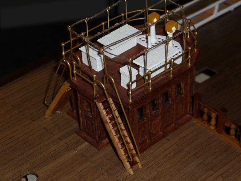
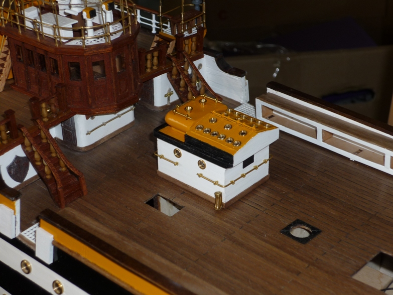
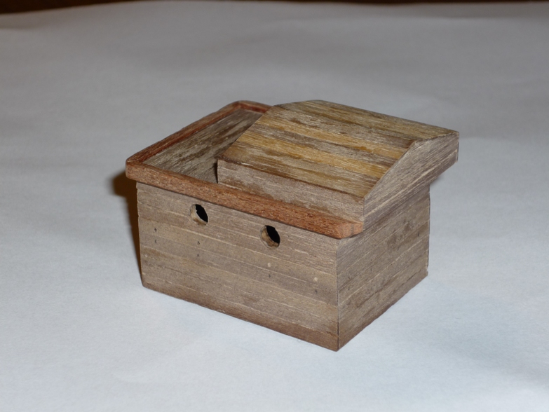
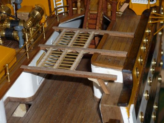
Deck houses I I do not have pictures of all steps in the construction of the three deck houses. However, there are a few things I would like to point out. This deck house goes on the quarter deck. It consists of a plywood frame and around a million pieces of mahogany - fun thing to make. When fitting the ladders, I realized that the stairs were to wide. So I shortened the step and sanded down the sides of the ladders - that did the trick. Here is the finsihed deck house in place. There is a small deck house on the main deck. Here it is before painting. And here it is in place on the main deck. /Lars Peter