


tkay11
-
Posts
1,797 -
Joined
-
Last visited
Content Type
Profiles
Forums
Gallery
Events
Posts posted by tkay11
-
-
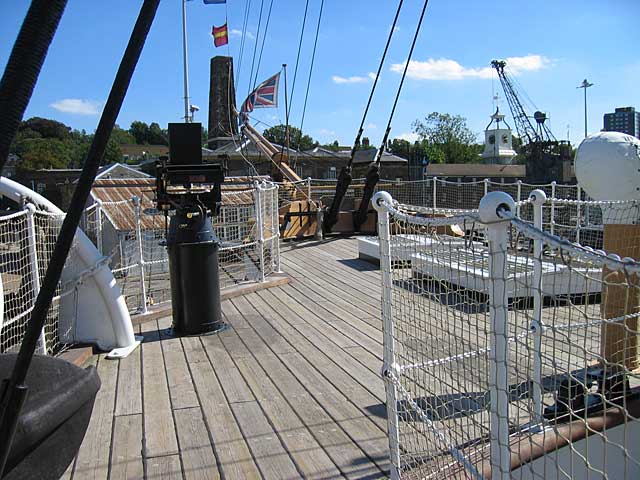
Unfortunately I've lost the photos I took of the deck of HMS Gannet, a Victorian sloop of 1878 at Chatham Dockyard (I was interested precisely in the treenails as well as the details of the hanging of ropes). However, I attach the copy of the photo from their website of the forecastle deck.
This shows that on this ship at least you can see the treenail sites, or rather the plugs quite easily. However, the colour of the plug matches that of the deck, albeit the plugs are a bit lighter. In real life, rather than in a photo, the plugs are even more distinct. So, as has been said before, it seems important to match the colour of the treenail site to that of the deck, and maybe to allow a ring to show round the plug (although no ring was visible on this ship's plugs).
I am sure others will have pictures of Victory or other ships that will add to the discussion, though.
Tony
-
Just to back up what Wayne is saying, I have been using TurboCAD for a couple of months whilst drawing up plans for the longboat on my model and although at first it was all very daunting, I am now more and more comfortable with it. There are lots of excellent tutorials which are free on the web and on this site for TurboCAD, including tutorials on lofting ships frames in 3D. On top of that I've benefited from tremendous advice from the pros on this forum.
It's like any software -- there's lots to learn if you're new to it, but if you take it step by step it's no big deal really. And once you have the hang of a few basics you see its tremendous potential and and become eager to learn more.
With every new version of TurboCAD, the prices of the earlier versions drop even further. There are excellent deals on Amazon for v18 now.
Tony
- trippwj, thibaultron and TomShipModel
-
 3
3
-
Sjors, I was only joking about the animation! Of course I like it!
You obsessive compulsive joker!
Tony
-
I have found on the web a wonderful tutorial called 'LOFTING TUTORIAL: A ship hull in 3d' which you can download as a pdf file and which answers perfectly how to use TurboCAD to loft frames.
I hadn't realised there was a function called 'lofting', but of course the moment I found it, a whole host of answers to my problem came at once. Thus 'prisms' are part of the lofting function. They all let you link different planes and points.
Sorry if this is incredibly obvious to CAD users, but I'm posting this in case it's of any use to others who like me are starting up in the world of CAD lofting.
Tony
- harvey1847 and Pete38
-
2
-
Sjors, I notice that when looking at the screen you seem to be writing your signature over and over again. Is this a sign of obsessive-compulsive disorder? It seems to be a hazard associated with model ship-builders.
By the way, I reviewed the research I'd done before and if you do an internet search you'll find the same range of opinions which verge to: ok for wood, not for brass but ok for aluminium, expensive for what it is, ok for infrequent small jobs.
Also Dave is quite right. The Unimats now sold have no relationship whatsoever to the original Emco versions of their lathes. The new 'classic' is made predominantly of a moulded plastic, whereas the originals were entirely metal. I hadn't realised that Frolich was using the earlier version, so thanks for that info, Dave!
Tony
-
I'm sure others will be much better qualified than I to answer this question. I'm only chipping in because I was at one time very interested in getting one myself and in MSW1 there were lots of discussions about this.
Most of the comments I saw were fairly negative about it, citing lack of precision, the business of re-assembly every time you wanted a new function and its lack of power. The general opinion seemed to be that it was better to go for individual cheap tools. Thus some Chinese-made lathes were touted as being worth-while.
On the other side, I have noted that Bernard Frolich in his book 'Art of Ship Modeling' used a Unimat jigsaw, and others have used it quite happily. It may well be that for irregular use and small jobs (such as the ones we generally have in modelling) it is more than adequate.
When I was looking at it, I thought more of buying the slightly more expensive metal line set. However in the end I spent my money on a circular saw as I thought that was what I was going to use the most. I'm still hankering after a lathe, though, but there's no room. And that's one good reason for a Unimat -- when there's not much room.
Looking forward to the heaps of replies you're going to get!
Tony
-
A few things I found on the Proxxon FET when setting it up:
1. I use a digital vernier caliper to make sure the fence is square by measuring the ends from the side and using the depth gauge. Once set up it seems to stay perfect
2. I use a cheap comb for African hair (just over £1) as a featherboard. It was simple to get it to a 2mm dimension simply by running it through the saw. It will probably go finer if I bother to cut it again. The handle it already has is perfect for holding, and so far I haven't needed to angle it by cutting across the base.
3. I oiled all the screws on the adjustment slide to make the adjustments really work smoothly (and I don't have it centred as it is the offset that matters). The micro adjustment works well for me now.
4. I made sure the saw was really vertical by using a set square and then clamping it securely. I don't intend at the moment to do angled cuts, so that seems fine.
5. I'm using the 50mm blade, 0.5mm thick with 100 teeth (Spring Steel Cutting Blade Ref: 28020) that comes from one of their other saws as it has a much finer kerf than the one supplied and, because of its smaller diameter, really does go below the table so that you can raise it to any level you want. The regular blade at its lowest comes to about 1mm above the board.
I'm still learning how to work this thing nicely, but it seems to be doing the job just fine! However, I am aware that others using this saw have complaints about its level of precision and the amount of time you have to fiddle with it to get it just right.
Tony
-
Yes, indeed that's it. And it works fine for lines. The only trouble is that when I try to do exactly the same with a perpendicular, the supposed perpendicular falls away at a variety of degrees depending on the position of the mouse instead of to the opposite surface and it doesn't snap to anything except to the start point. The object itself as a whole is at right angles to the world view plane and is on that plane.
However, your drawing showed me the obvious solution -- just to draw a line down the middle of the beam using the M snap. This has solved the problem I was faced with.
So it's like a lot of things. It's an oddity, but luckily I have two good workarounds now!
If you know what I'm doing wrong, then of course I'd be glad to know. However I would hate to have you bothered by ferreting around when it's now no longer a problem.
Thanks a lot for the help and encouragement, as well as for solving my problem!
Tony
-
That's just what I wanted, Alexandru. Perfect. Thanks very much!
Tony
-
This is one thing the UK has right. You can buy them by the boxful here without any questioning from any online store, including eBay.
Tony
-
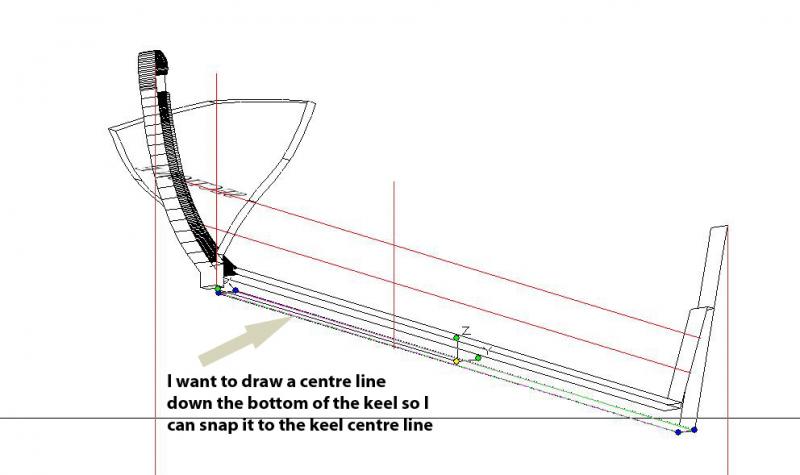
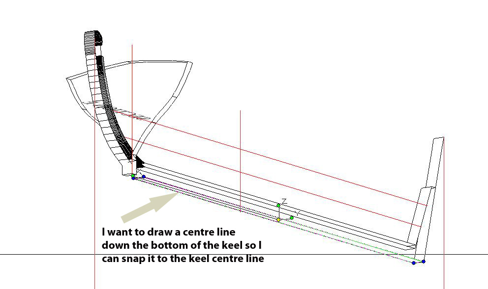
It's the bottom of the keel, as per the attached picture. It's not that I don't have a work around, since I can draw lines on the plane to which I can attach the keel. It's more that I want to find out how to put in a centre line in order to align it with the keel line I have made on the drawing.
For some reason, even though I try to make the workplane conform to the facet (highlighted in the drawing) I can't get a line tool or a perpendicular line to work as I would wish in relation to the drawing. I would point out that the lines are exploded and not part of any group.
You'll notice that in this drawing the stem has multiple nodes. I'm correcting this in a new version. Also ignore the keel on the section that is lying across the keel at the bow, since that was there only for alignment purposes.
Thanks, though, for looking! Any suggestions welcome.
Tony
-
Thanks for the links, SketchupModeller. They will be really helpful.
At the moment I've been spending an hour or so trying to draw a perpendicular line to a 3D object in TC. I have yet to find the trick. But it'll be there somewhere.
Tony
-
Thanks so much for the reposting of this wonderful build. It's as beautiful as it is inspiring.
Any chance of your reposting the pictures of the longboat build for this model?
I am trying to do a longboat for my own model at the moment, and it would be great if I could have another chance of looking at yours. I have been using layers of MDF as you did, and started carving out the shape. I forgot to leave space for the frames, so there's a bit more sanding being done at the moment. I seem to remember you covered your longboat in clingfilm to stop the frames being glued to the mould, but it would be great just to have a look at the overall sequence again if at all possible.
(Hoping I haven't somehow missed your reposting of those pictures when going through your log),
Tony
-
I second Wayne's comment about nodes. At first I was tempted to use too many as it is so easy just to follow the path and click. But the trick of a smooth outline is to use as few as is possible -- two if possible (one at either end).
As for being the first person to make a simpler hull in TC, I've already done that. The only trouble is that it's not quite watertight as it has no planks. Still, Wayne's right -- you only get there by sticking at it.
Tony
The key is to make sure all the beziers have the same number of nodes.
-
There is a lot of videos on YouTube for TurboCAD. The ones by Paul Tracey gave me the initial kick-start for the 3D side. His list of free training videos can be found if you click here. They are very easy to follow and they certainly eased the learning curve.
In terms of the manual, I agree the web links can be confusing. The pdf version is a little easier to navigate. You can choose to read the pdf version if you go to 'General' in the 'Options' tab and choose 'Use offline help' in the menu.
I've also just downloaded the free version of SketchUp. This is a very much simpler programme to get the hang of, more intuitive and has a much cleaner and nicer interface. Although SketchUp clearly does not have quite the range of TurboCAD, you'll see from the modelling done on the site with SketchUp is quite fantastic. The only limitation I have found so far in experimenting with SketchUp is that you can't load pdf files into it. You'd have to convert pdf to jpeg for importing (unless someone more knowledgeable tells us otherwise).
So my advice would be that if you feel TurbCAD is too much, switch to SketchUp for an easier ride which may well give the same results. As for me, I'm still undecided -- having invested so much time in learning TurboCAD!
Looking forward to anything you produce in any programme,
Tony
-
Wayne, that's still pretty cool. I reckon I can approximate this with a series of 3D polygons, which I guess are prisms. Anyway, I'll have a bash. Your suggestions and your pictures have given me much encouragement -- I especially like the boat as that gives me an idea of what I should be aiming for. I'll have fewer seats and no cannon on mine, though!
Thanks very much
Tony
-
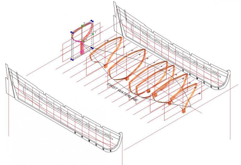
Thanks, Jingyang. I can render and shade surfaces of enclosed spaces. What I'm stuck on is how to get the 'assisting curves' stage you show in your first picture. Attached is where I am so far.
I can then make the keel, stem and stern with no problem. Oh, and I've just noticed from my own picture that I've put the stern section at the wrong station line. Still, you'll get the idea!
I can't quite figure out how to mould the sides of the sheer plan to the central line of cross sections. I reckon it must have something to do with tracing the waterlines from the half breadth plan as those are the lines that I can see on your first picture but I still haven't attempted that. However, now I've seen your pictures I'll have a bash later today.
Also I don't understand what the top curved line over the boat on the body sections represents in the plans since it is an open boat.
Thanks also 'capnharv2'. Yes, I've studied Kemp's article but it presumes you're using the CAD to generate plans from which to make a wooden model. It doesn't go into the 3D creation. I'm using TurboCAD Pro 18 which I got by chance for almost nothing from a friend who gave up on it. As you can see it has the rendering facilities, but I thought all versions of TurboCAD had them as well.
Thanks again for so much help so quickly!
Tony
-
I have been so impressed by the wonderful quality of the CAD builds on this site that I have been trying to teach myself how to convert the 2D plans to 3D in TurboCAD. I've been doing this by using the 2D plans of the longboat on the Cutter Alert based on the Anatomy of the Ship book.
I had been using the 2D plans to make the longboat in wood, and that is taking its own course. However, I am stuck in the CAD programming when trying to figure out how to obtain the 3D hull shape from the verticalised sheer plans. So far I have been able to flip the sides and move them together with the horizontal waterlines and body plan to obtain a box, but I can't quite fathom how to form the hull from this point.
The instructions for using CAD on this site refer to 2D lofting (as far as I can see), so if anyone can point me in the direction of instructions on how to move to the next step of 3D creation from plans I'd be very grateful.
The essential reason for my interest is (1) to be able to continue to do some form of ship building in a practical way while I am travelling (something which I have to do for a very large proportion of my time) and (2) to visualise plans in a new way.
Any pointers most welcome for this two-fold 3D novice!
Tony
-
-
Just to add to the chorus of praise, I'm delighted you're doing this log in such a detailed way. It really shows how much cross-fertilisation there is between the types of build, and that there are in fact so many different ways to build a ship. I'll be following this one right through to the end.
Great stuff!
Tony
-
If you look closely at my pic, Sarah, you'll see the smile is accompanied by the knowing wink of recognition of enjoyment and its source. But maybe the resolution is not good enough --- you'll just have to take my word for it.
Tony
-
What fun, Sarah! This one really brought a smile. I much look forward to the rest. We'll have to keep a watch on Sjors' translations though - he might have the temptation to slip in a joke or two!
Tony
-
I've used Liberon wax filler sticks used in furniture repair. It's really easy to apply and wipe off. These wax fillers come in a lot of shades so it's easy to achieve the right level of difference from the wood of the planks, and provides a subtle effect. I had this tip from Daniel when he was on MSW 1.0 but I've seen a few others do this as well. I did try melting it into the holes but it turned out to be just as easy to scrape a few fragments off and wipe them into the holes.
Tony
-
It used to be owned and given free by Google. It was then sold to Trimble who have a two-tier system. There is a free version and a version you have to pay for which has more features. You can find it by searching for 'SketchUp'. Wikipedia has an entry for the programme. If you want a direct link to the download site, click here. I believe most CAD programmes will do the same.
Tony

Panthere 1744 in 3D
in CAD and 3D Modelling/Drafting Plans with Software
Posted
I can't answer your question, Bava, but I can't see why you have to be daunted by the quality of other CAD builds. This is a familiar statement amongst the wood builders too. The fact is that your quality of craftmanship is very high indeed. We are all learning from each other in this business, and clearly some have had a great deal more experience than others. For me, I have never felt 'daunted', but what others have done certainly does inspire me to find out how they do it so that I can try my hand as well.
I've been following your build with great interest, and I really like the way you've patterned the wood, the figurehead and bows. What would be very helpful to me as I learn from you would be some indicators of how you achieve the various bits of the build as you go along. That's what I try to do with my own build log. I realise I am a total novice, but I also know that others who are novices are often struggling with the same problems I have faced, so I try to explain how I overcame them -- even though others on this site have achieved better and more elegant solutions to the same problems.
There's simply too many builds to follow each and every one to learn how others have done it, so the more info that can be given with each log the better!
So, in short, don't feel 'daunted' but know that you are also a leader for some of us.
Tony