


tkay11
-
Posts
1,822 -
Joined
-
Last visited
Content Type
Profiles
Forums
Gallery
Events
Posts posted by tkay11
-
-
Just adding to the chorus. I'm delighted you could re-post as yours is a build I was following avidly.
Tony
-
Thanks a lot for re-posting this, Jamie. I've just been dabbling in building my ship's boat, and as that meant doing a solid hull I've been interested in any solid hull work. Your work is really beautiful. I look forward to the rest and the tutorials as they come in.
Tony
-
Hello Kester! I was wondering if you're going to post pictures of your Sherbourne. You've been so helpful on a lot of builds, I definitely would like to see yours. I think you used to have the title 'Sherbourne - So far so good'. But of course that link has gone with MSW 1.0.
Tony
-
I am in total agreement with Klaus. There are bookshops in the UK that would handle this )for example, the Model Dockyard, or Pen & Sword). I am fairly sure model shops such as Cornwall Model Boats would also sell them. I would have bought books from Seawatch, but have been put off by the huge expense of the posting.
Tony
-
It's wonderful that you have decided to re-post your log, Alexandru. I am just trying to build a ship's boat and I'd taken quite a few tips from your own build -- apart from the fact that your whole build is magnificent and inspiring.
Thank you
Tony
-
It's great that you decided to repost, Sumner. I was missing that log. It's been such a great help with my own build. Looking forward to the rest. At the moment I'm trying to build a ship's boat for it -- which has been another fun learning experience.
Oh, I forgot to add. I saw after I posted this message that you've got much better tags than I. Very good idea to have the different spellings of Sherborn in light of the different names for the plans.
Tony
-
It seems to have taken him from Dec 27 2010 to Feb 25 2011. I find it just as amazing that he can do it in such a short space of time.
Tony
-
Thanks, Jay and Garward. Very helpful!
Tony
-
Thanks a lot, Garward, for the tips. I've been thinking about how to use the Proxxon cutting discs to make such pieces, but the fact is I don't have a lathe and I can see how useful it is. Is your lathe one of the Chinese made ones? If so, which one, and have you been happy with it? I might buy one next year when I can afford it!
Tony
-
That's an excellent explanation, Dave. Thanks very much for taking the time to enlighten me! It also explains why, when I searched Google for rope servers, the answers seemed to be entirely for archery.
Tony
-
-
Thanks a lot for reposting this, Caroline. I'm thinking about making the ship's boat, and your build has been very useful.
Tony
-
I don't know if this is the right place to post it, but while researching builds of the Cutter Alert, I came across this very interesting build which really is a scratch build, but not quite in the usual way.
It's based on the use of Sketch Up and is really just a CAD build, but it is done as though on site and stage by stage. You can see it at http://sketchucation.com/forums/viewtopic.php?f=333&t=33757&sid=f942299afdf93114ad1c504acb5c6417. Or, if you want to click, click here.
Sorry if the topic needs to be moved!
Tony
-
Very nice to see such detailed instructions.
Thanks very much
Tony
-
Haha, Carl! That's now as far as I posted previously. Coming up at some time in the future:
Cannon rigging
Shot racks
Deck fittings continued
...and... perhaps (if I am at all successful) building a longboat for the cutter. The trouble with this particular scheme is that I was following the build of a 1:48 Victory by someone from South America. In it there were some really nice ideas about building a small longboat using layers of MDF (Medium Density Fiberboard). The trouble is that build seems now lost for the moment and I am hoping the person manages to re-post it all. Nevertheless, I have drawn up plans for the longboat and have cut out the first overall shape. If you don't see any more posts in this build about a longboat you'll know I've not managed it!
I also seem to have spent ages learning about cutting more accurately, making lots and lots of small parts, learning from other people's builds, etc. It's going to be quite a relief to get back to what is beginning to look like a boat!
Thanks for looking in,
Tony
-
After the torment of trying to get the carriages right, I decided I’d start another build whilst thinking of how I might approach the building of the blocks and tackle for the guns.
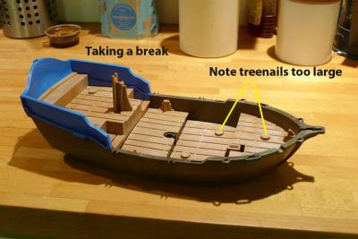
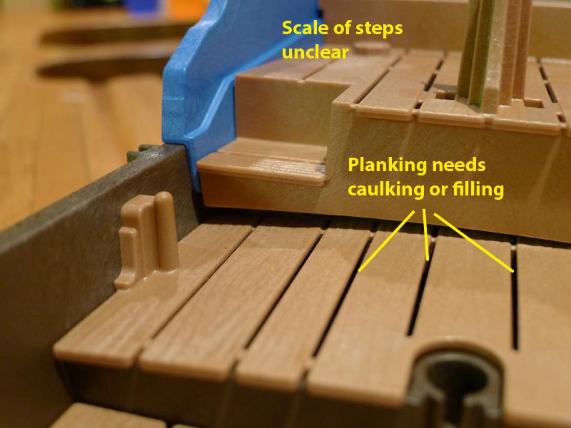
I settled on a rather rare pirate ship, whose plans have only recently been found. I decided I’d pretty much scratch build it from some plastic pieces I found in a box lying around in my daughter’s home.
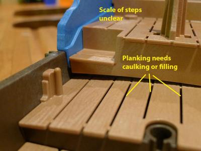
You’ll get the idea from the following pictures. At the moment I’m still struggling with the size of the treenails on the decking, and am having trouble scaling the stairway.
Then there’s the vexed question of the planking. I decided that the lower decks would benefit from a lot more ventilation, and so left the planks separated along their length. However, I could be persuaded to fill them with some black paper or other caulking.
You’ll probably notice the colour scheme, too. This is entirely in keeping with the fearless Captain Tony’s wishes to be noticed and recognised at once.
The main thing, though, that I’d like help with from others on this forum, is to find out the name of the ship. I have the captain’s name, but unfortunately no mention is made (in any reference I can find) to the name.
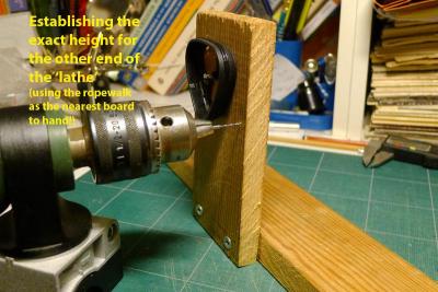
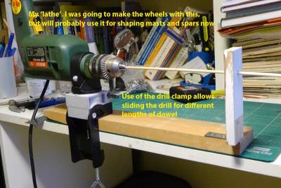
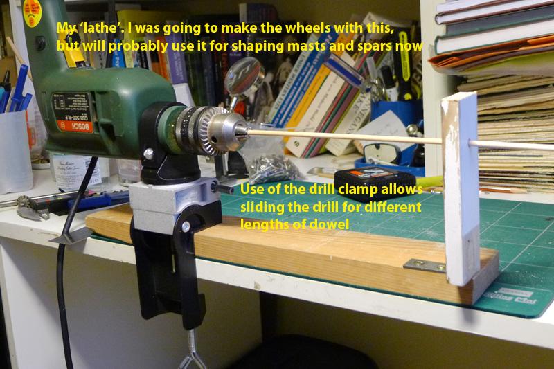
As part of my recuperation, I also made myself a pseudo-lathe using my electric drill in the same manner others have used on this forum. I had been intending to use it to make wheels, but in the end decided just to stay with the kit wheels. I am sure it’ll be useful for the masts and yards.
Tony
-
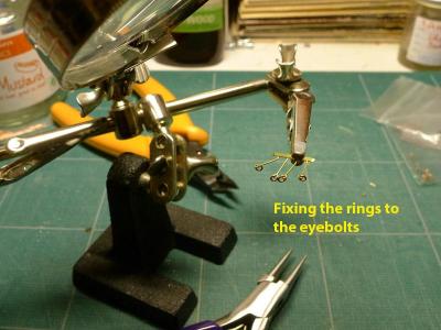
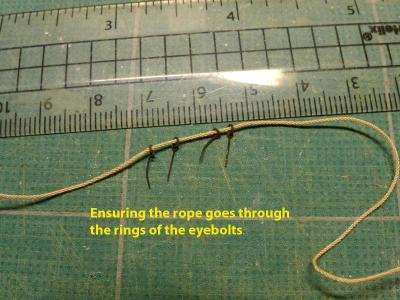
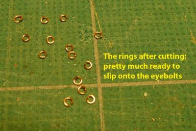
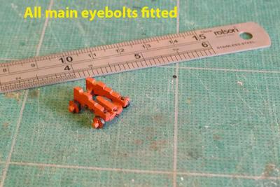
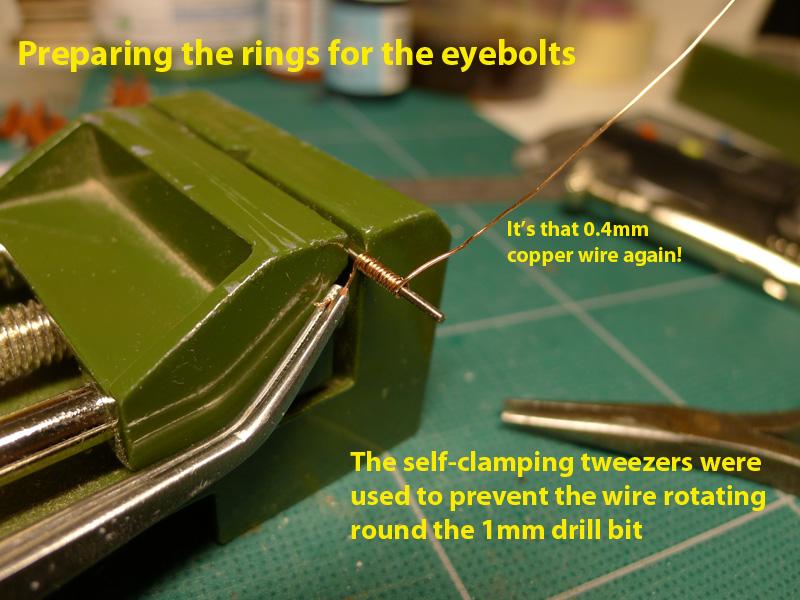
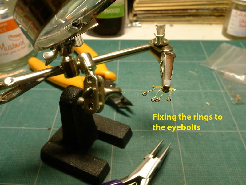
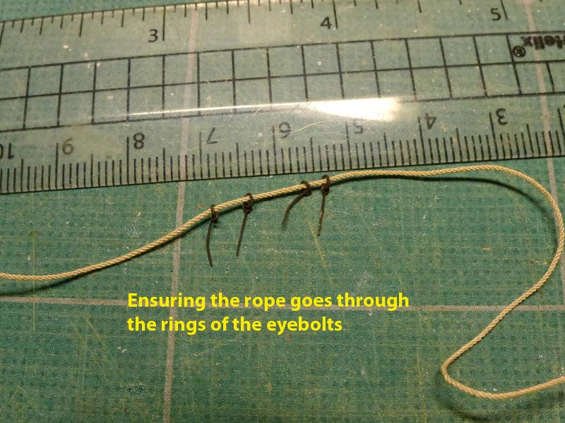
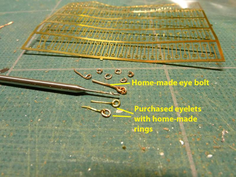
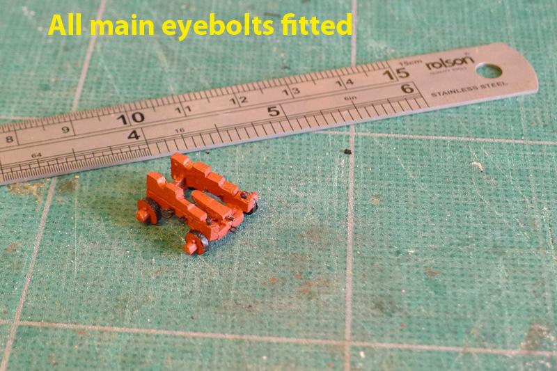
The carriages then had their eyebolts put in. At first I tried to make the eyebolts myself, using 0.4mm copper wire, but the results were too big and too rough. So I resorted to buying a pack of 0.3mm brass etched eyelets after a hint from Dirk/Dubz who did the same. These are really great! All I then had to do was to make the rings – which I did as so many have done, by winding 0.4mm copper wire round a 1mm drill bit, then cutting off the rings using the side-cutting pliers.
I used brass blackener, as usual, for all the rings and eyebolts.
This now leaves me with the rest of the gun tackle to make and the blocks to hold the ropes. That’s going to take me quite some time as new skills are required!
Tony


-
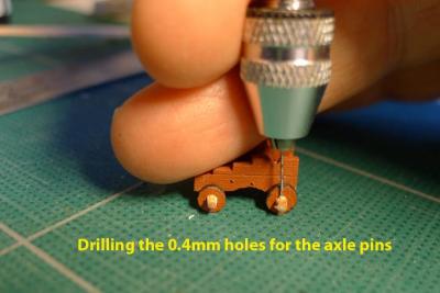
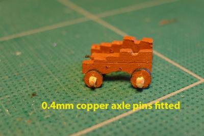
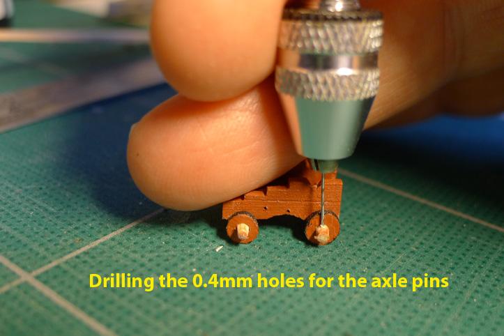
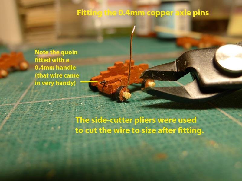
After the wheels were put on, the axle ends were sanded down to 1.3mm from the wheels, and 0.4mm holes were drilled to accommodate the axle pins. The axle pins were made of 0.4mm copper wire, snipped off by some really excellent (but amazingly cheap) side cutting pliers of the type used for printed circuit boards. The axles were then painted.
Tony

-
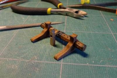
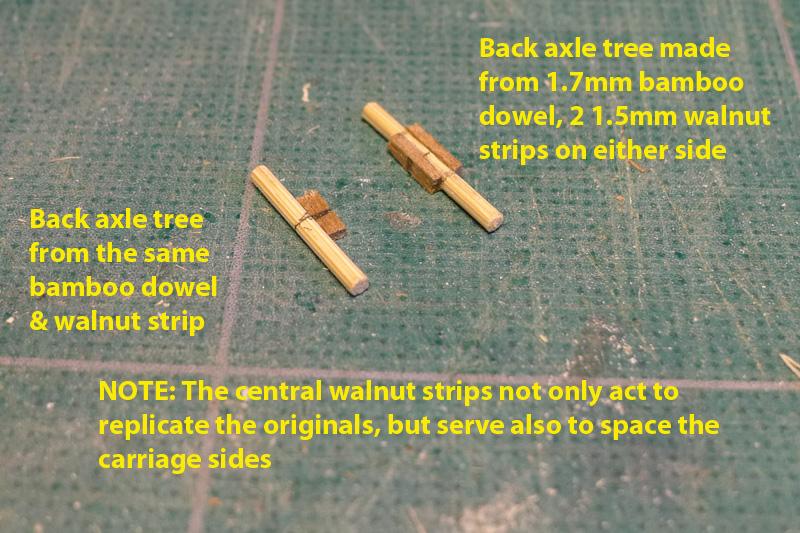
The bases of the carriages were then simply made using 1.7mm bamboo dowel (that drawplate sure comes in handy) and walnut strips on either side to mimic the axle tree.
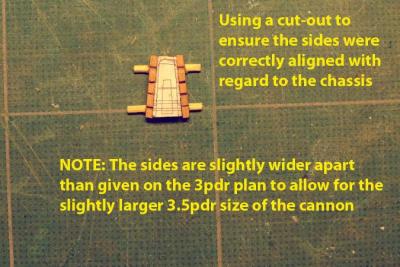
The sides were then glued to the axle trees with PVA glue, and their alignment was made using a form cut from the plans and pasted to the cherry strip. The sides were 1mm further apart than dictated by the plan because of the over-size cannon I was using.
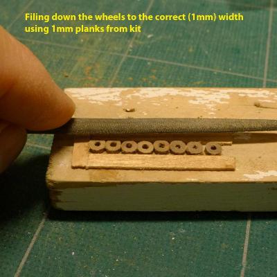
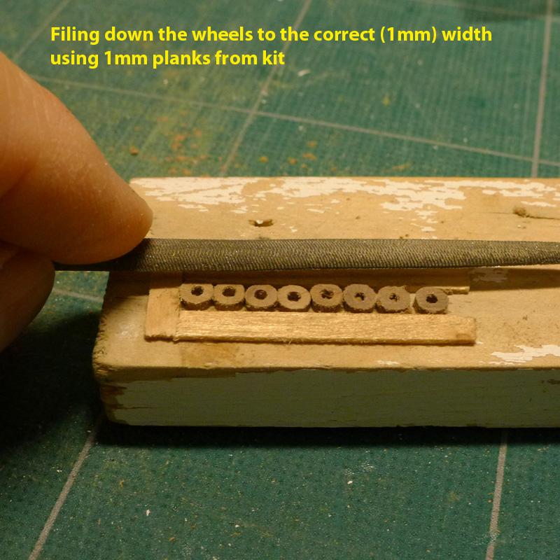
The kit wheels were filed down to scale using a simple jig made of 1mm strips of lime that had been unused from the kit.
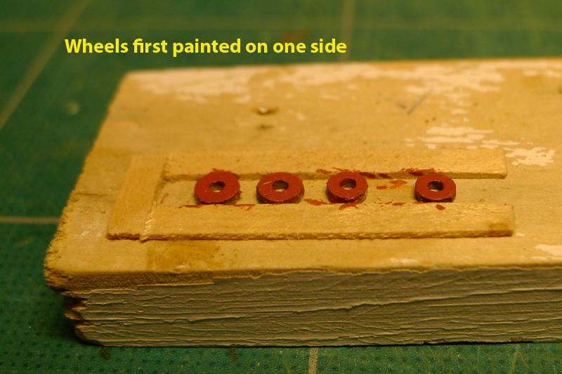
Because of the variety of woods I had used in making the carriages, and because I knew I could not achieve the kind of beautiful finish others have achieved, I decided I had to paint them in red ochre.
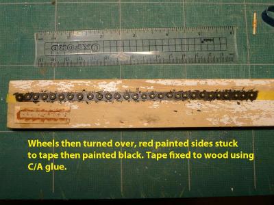
I had experimented with putting strips of black paper round the wheel rims to mimic the iron hoops that I have seen on other wheels, but in the end decided to paint the black on the rims. This I did by painting one side in ochre red, then, after it had dried, sticking the wheel face down to some Tamiya masking tape. I then painted the edges red to ensure that there was a seal to prevent any black paint escaping to the sides, and finished with two coats of black round the edges.
Unfortunately, although the wheels are now the right kind of width, the finish is extremely rough. Next time I’ll try hard to make my own wheels.
Tony


-
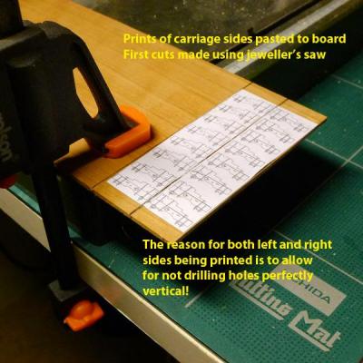
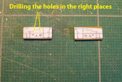
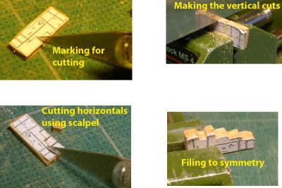
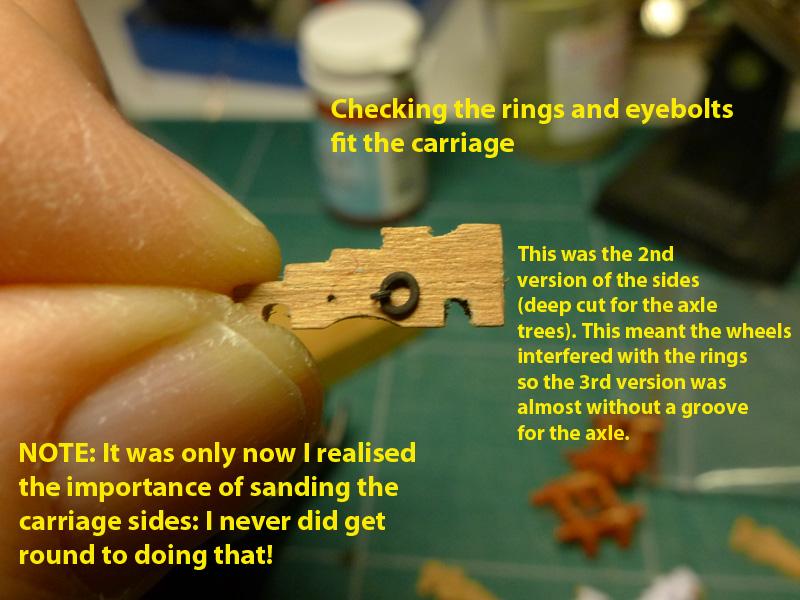
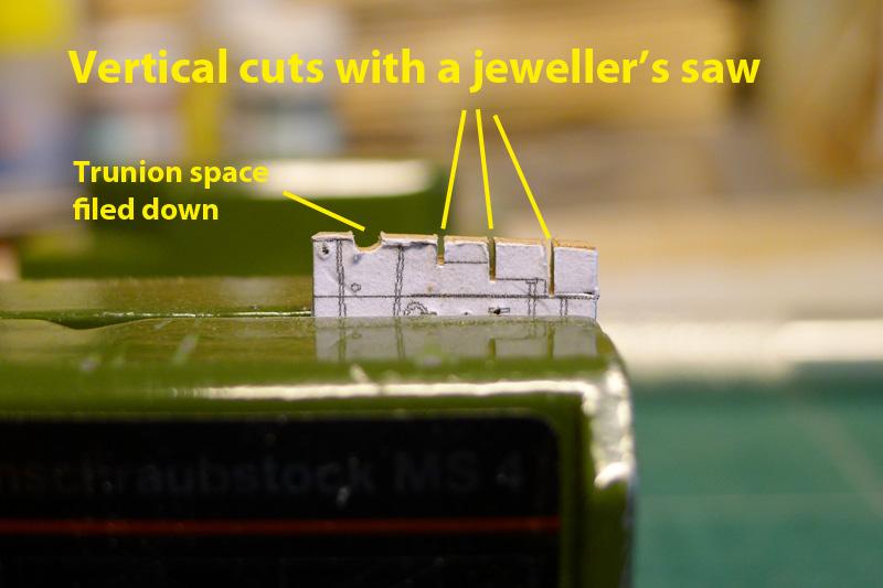
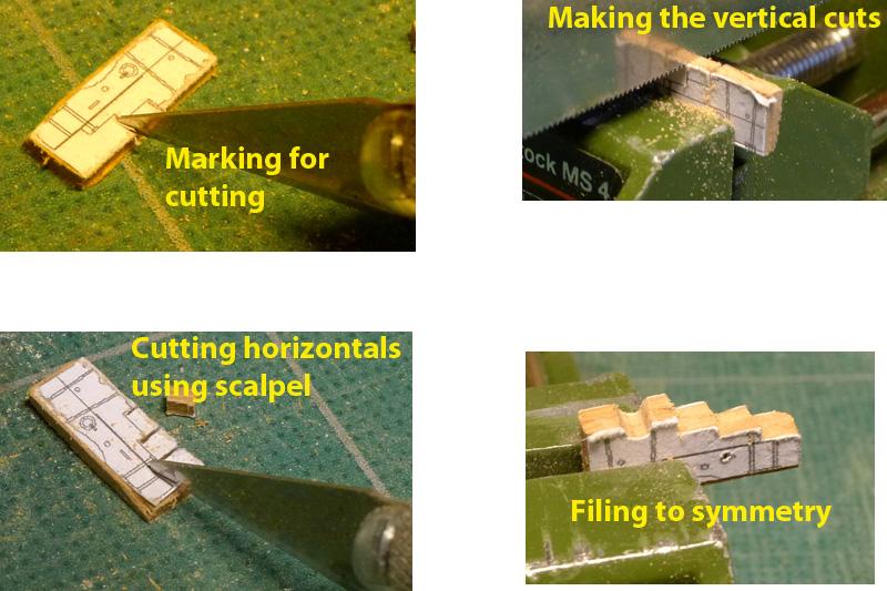
My dissatisfaction with the first attempt at gun carriages led to the 2nd where I tried to cut out the carriages from 1.6mm cherry wood board. I found I couldn’t manage to cut out the sides accurately so went back to thinking how I could do this. My answer was to scale the 4pdr carriage designs found in the AOTS book on the Alert down to 3pdr scale and then print out a sheet of them. To do this I used Photoshop rather than TurboCad as I found it faster. The printouts were pasted directly on to the cherry board, then cut them using a combination of jeweller’s saw and scalpel blade.
Tony

-
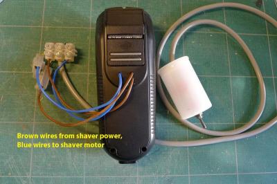
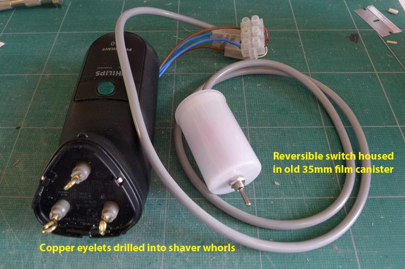
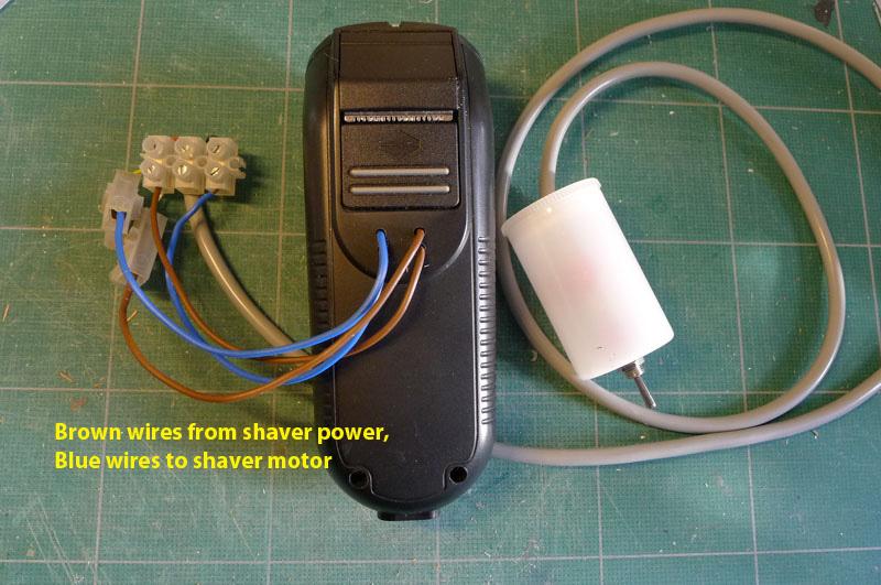
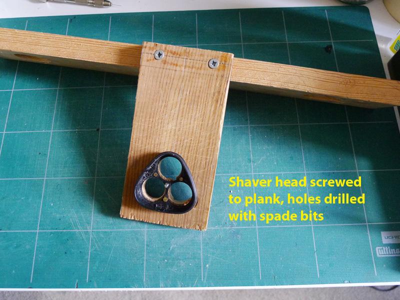
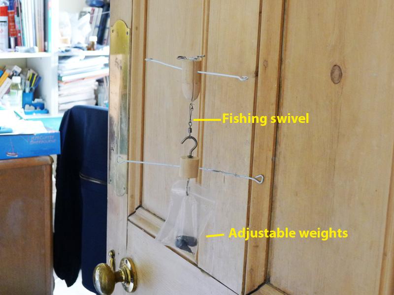
Whilst still thinking about the carriages, and being unsatisfied with the first attempt, I thought forward to the need for making breeching and other rope for the cannon as well as the anchors. So I decided to make a vertical ropewalk using the basic design shown in Ken’s (BRGreen) posting (which is now lost unless he re-posts it!).
The only differences in my ropewalk were
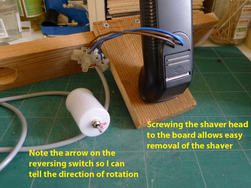
1. using an old 35mm film canister to house the reversing switch;
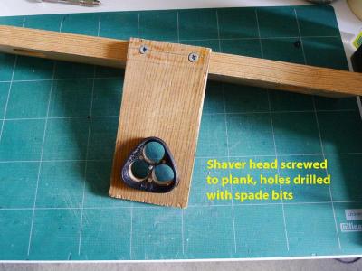
2. keeping the old head of the shaver and screwing it direct to the faceplate so that it would be very easy to pull the shaver off the machine.
3. keeping the back of the shaver on and drilling holes for the wires from the power source and to the motor.
I soon found out that the fishing swivel I was using was useless, so bought a ball-bearing swivel which improved rope-making considerably. I also found that the weight I had to use was far less than first expected. 10gm seemed to do the trick for the thread I was using.
The breeching rope should be 4.25” circumference. This translates to 0.54mm diameter at scale. I achieved this using some old thread of my mothers. However, I have so far only been able to make left-handed thread from the right-handed thread that I have. I know I should be able to unwind the right-handed thread in order to make right-handed rope, but so far I have failed to manage it.
Tony


- nobotch, Andrea Rossato and Nirvana
-
 3
3
-
This part of the log was added on Jan 16 2013
===
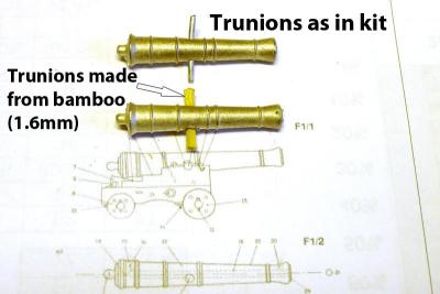
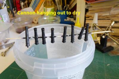
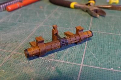
The 3pdr cannon were next on the list. Most of those who build the kit talk about how the kit cannon are oversize. Well, that’s true. Their length is 23.8mm (the equivalent of 5 foot, or a 3.5pdr)), whereas a 3pdr should be 4’6”. At scale 1:64 that would mean a length of 19.05mm. Seeing as I don’t have a lathe, I reckoned that I could live with the 3.8mm difference and use the kit cannon.
The only thing I didn’t really like about the cannon was the trunions. They just looked like very thin pins. So I decided to drill out the old trunions and replace them with 1.6mm bamboo dowel I made from barbeque sticks using a drawplate.
However, when I started work on the carriages I didn’t like them at all. The carriage sides were parallel (not following the lines of the cannon), the axle trees had square axles, the wheels were so thick they made the carriages look like go-karts or quad bikes, and the carriages themselves were too long.
I therefore decided to embark on the rather foolish notion of building the carriages myself – especially after seeing the work of others on this forum (e.g. Dirk’s/Dubz and Daniel’s/Siegfried). The reason it was foolish is that, as you will see, the finish I achieved was not very good. All the same, the experience was worth it as I think I’ll be able to do much better in the future.
I decided to make carriages that at scale would be 3pdr, whilst continuing with the 3.5pdr cannon of the kit. I could have made the carriages equivalent to 3.5pdr, but my whole thinking was dogged by the well-known problem of the kit: notably that the aft two gunports are so low that the cannon only fit with difficulty. I therefore had to make a carriage that would allow the cannon to go through these aft gunports with ease. I still don’t know how others achieve this trick!
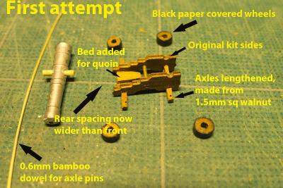
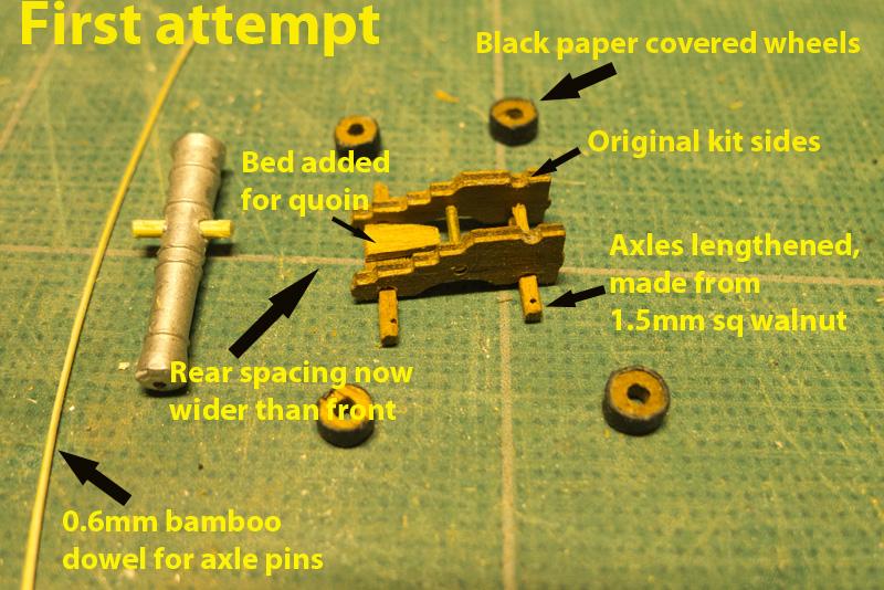
Below you’ll see the pictures of my first attempt. In this I used the original kit carriage sides, but replaced the axle trees with longer axles made from 1.5mm sq strips from the kit, a roughly fashioned bed for the quoin, and paper covering the wheels to look like the iron hoops.
Tony
-
Now, as far as the windlass is concerned (and I can’t really determine whether my windlass is concerned at all), I coated the pawl bitt and windlass with refined linseed oil (as suggested by Daniel/Siegfried) and stood them together to see if they would like each other.
I think they do.
That was all a very interesting set of learning experiences!
Tony
-
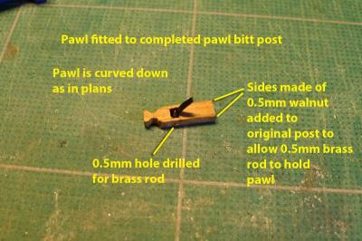
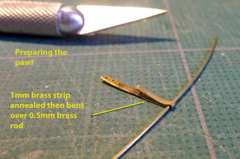
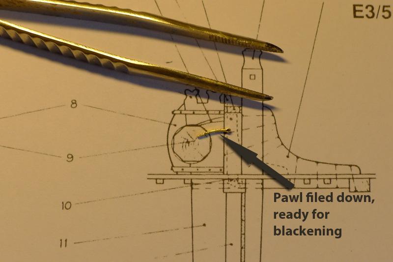
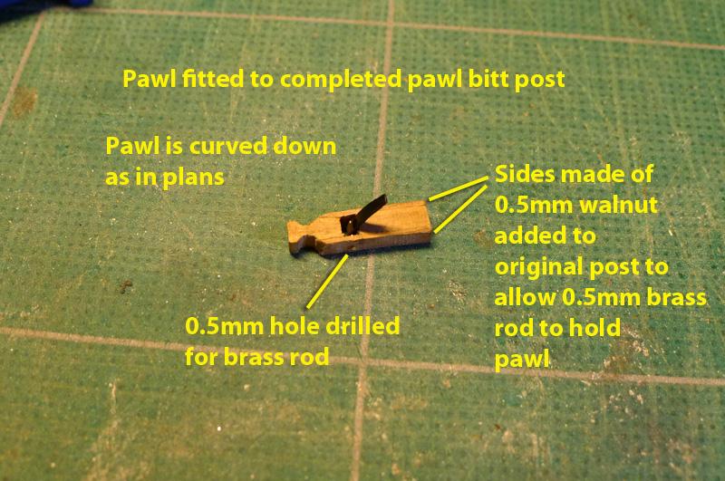
Finally, for this stage of my work, I came to the pawl bitt post. The kit suggested just sticking a strip of 1mm thick walnut into the post for the pawl itself, but this didn’t look at all right when looking at what a pawl should be doing.
So I decided to fashion the pawl out of copper sheet, and lengthen the post by 1mm so that it could take the pawl on a 0.5mm brass wire.
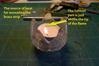
I made the pawl by annealing a 1mm strip of brass, bending it over the brass wire that I intended to use as its rod, cutting to the right length (0.7mm), and sealing the folded edges by soldering with silver flux. I then filed the brass down to the shape shown on the ‘Alert’ plans, and bent it to a gentle curve.
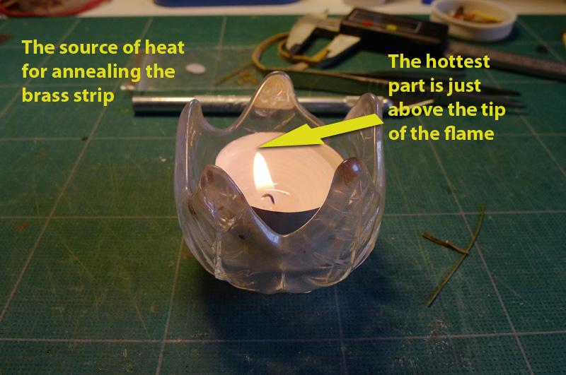
I found that annealing doesn’t seem to require red heat. I just held the strip over the tip of a candle flame and that seemed to do the trick quite well.
After cutting the pawl bitt post, I glued two sides of 0.5mm walnut to the post, leaving a gap between the two bits of the post, drilled a 0.5mm hole for the wire, and inserted the pawl.
Tony


Lady Nelson By Ray - FINISHED - Amati/Victory Models
in - Kit build logs for subjects built from 1801 - 1850
Posted
That was a real pleasure, Ray, to see the complete build. A lot of useful pointers for my Sherbourne which is a very similar ship. A beautiful model. I'm looking forward to the Diana.
Tony