Dennis Powell
-
Posts
15 -
Joined
-
Last visited
About Dennis Powell

- Birthday 04/13/1952
Recent Profile Visitors
261 profile views


-
 GrandpaPhil reacted to a post in a topic:
The Skipjack by Dennis Powell - using Wye River Models plans and materials
GrandpaPhil reacted to a post in a topic:
The Skipjack by Dennis Powell - using Wye River Models plans and materials
-
Canute reacted to a post in a topic:
The Skipjack by Dennis Powell - using Wye River Models plans and materials
-
Harvey Golden reacted to a post in a topic:
The Skipjack by Dennis Powell - using Wye River Models plans and materials
-
Roger Pellett reacted to a post in a topic:
The Skipjack by Dennis Powell - using Wye River Models plans and materials
-
Ryland Craze reacted to a post in a topic:
The Skipjack by Dennis Powell - using Wye River Models plans and materials
-
JacquesCousteau reacted to a post in a topic:
The Skipjack by Dennis Powell - using Wye River Models plans and materials
-
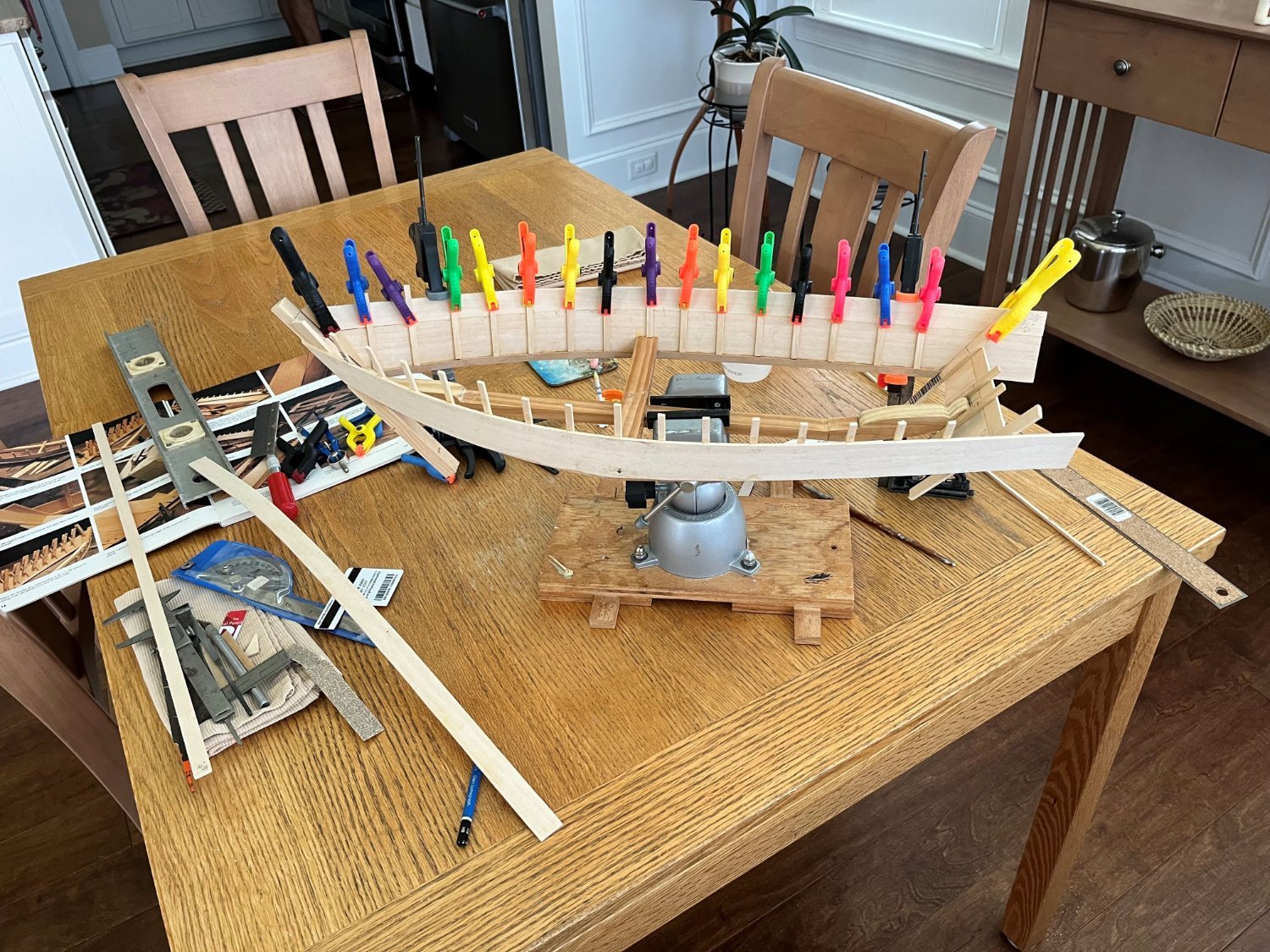
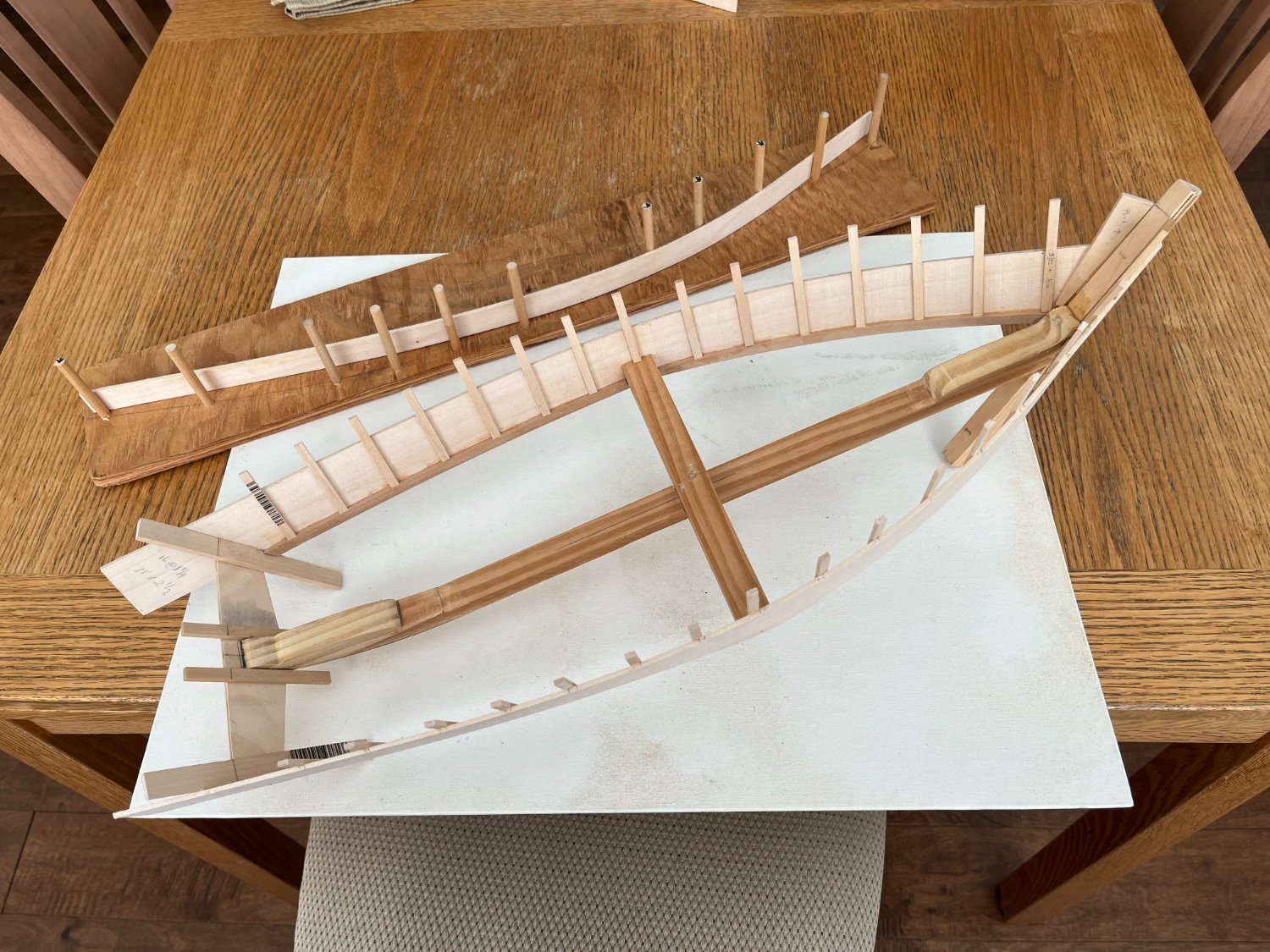
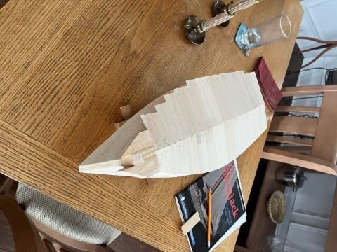
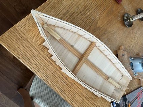
Thanks to all who have an interest in this build. I apologize for the slowness of my activity, but as with many project, life gets in the way! In my last post, I was installing the side planks and frames. Once these were installed, I began installing the bottom planks, 33 on each side f the keelson. No major issues, just tedious. This is where I am at this point. The left picture is looking from the bottom of the boat, showing the untrimmed starboard and trimmed, but not completely sanded port side. Also, the chunks at the bow are not yet shaped. The right picture is looking down at the bottom of the boat from the inside. After rough trimming, I will move onto the stem, forward worm shoe, stern post, center-board battens, keel and rudder assemblies. I probably missed something in my list. Hopefully I will catch everything in their proper order. Maybe this project will pick up speed, but I want to be careful. So, no promises.
-
bgilbertsound reacted to a post in a topic:
The Skipjack by Dennis Powell - using Wye River Models plans and materials
-
thibaultron reacted to a post in a topic:
The Skipjack by Dennis Powell - using Wye River Models plans and materials
-
thibaultron reacted to a post in a topic:
The Skipjack by Dennis Powell - using Wye River Models plans and materials
-
thibaultron reacted to a post in a topic:
The Skipjack by Dennis Powell - using Wye River Models plans and materials
-
I must have deleted an intermediate picture - where I used a batten on the outside of the port and starboard sides of the model, before they were cut. The batten would have started from the stemliner reducing the height of the sides as it reached the transom. Thus, the extra length of the frames and the upper portion of the second piece of the sides was cut away. Shown now is the starboard shelf to hold the deck beams. Note - always clean away any extra glue before it dries! This is as far as I have gotten with the build. Time to make some more sawdust! Thanks for watching, PS - I figured out how to reduce the size of the pictures.
-
Starboard second board attached to first, from stem liner to transom. Port side to folllow.

-
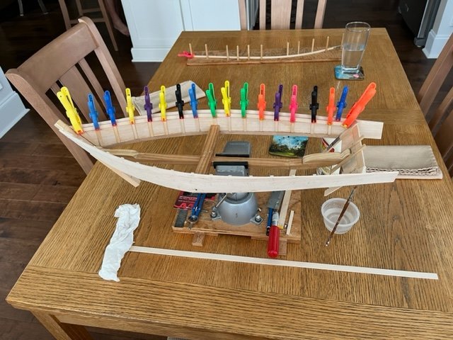
The side boards have been removed from the bending gig. The boards are glued at the transom, strongback and stem liner. Important to note the angle at the strongback has to be very accurate, as it helps determine the outward splay of the top edge of the side boards. If off by a very little, the effect will be obvious when the deck planks are laid. The chine log is installed, to which the frames are "bottomed". Important the frames are perpendicular to the chine log. The frames are long, as there is another side board running from the transom to the stem liner, edged to the top of the existing side boards. This will be obvious on the next picture. Knight heads are installed.

-
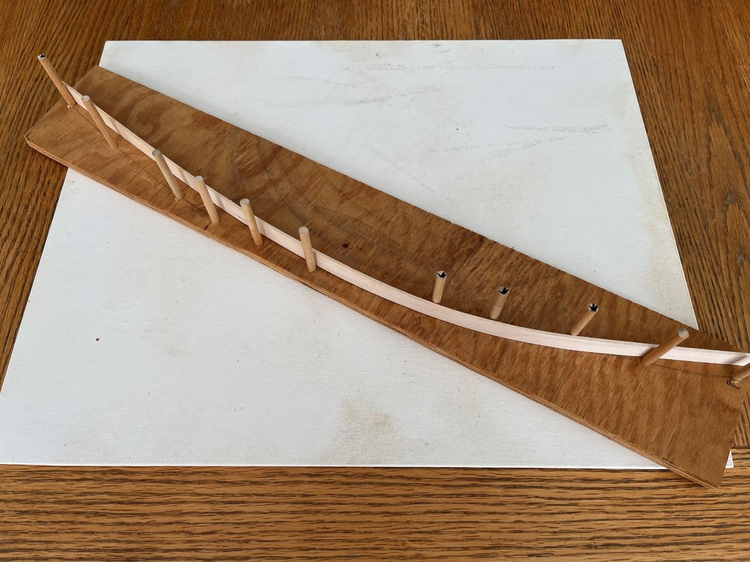
As I began constructing the model, I realized the need to bend some wood to the necessary curves. Thus, I created a bending jig. The base is a piece of 1/2' plywood with holes drilled to accomodate the shape of the hull. I didn't steam the wood, just held it under a hot faucet for a couple of minutes before either clamping or intertwining the wood among the stakes. For another hull. I can just redrill holes and move the stakes. I wet and dried the wood 3 times which was enough for the curve to hold. This jig was also used for the chine log and the shelf to hold the deck beams.

-
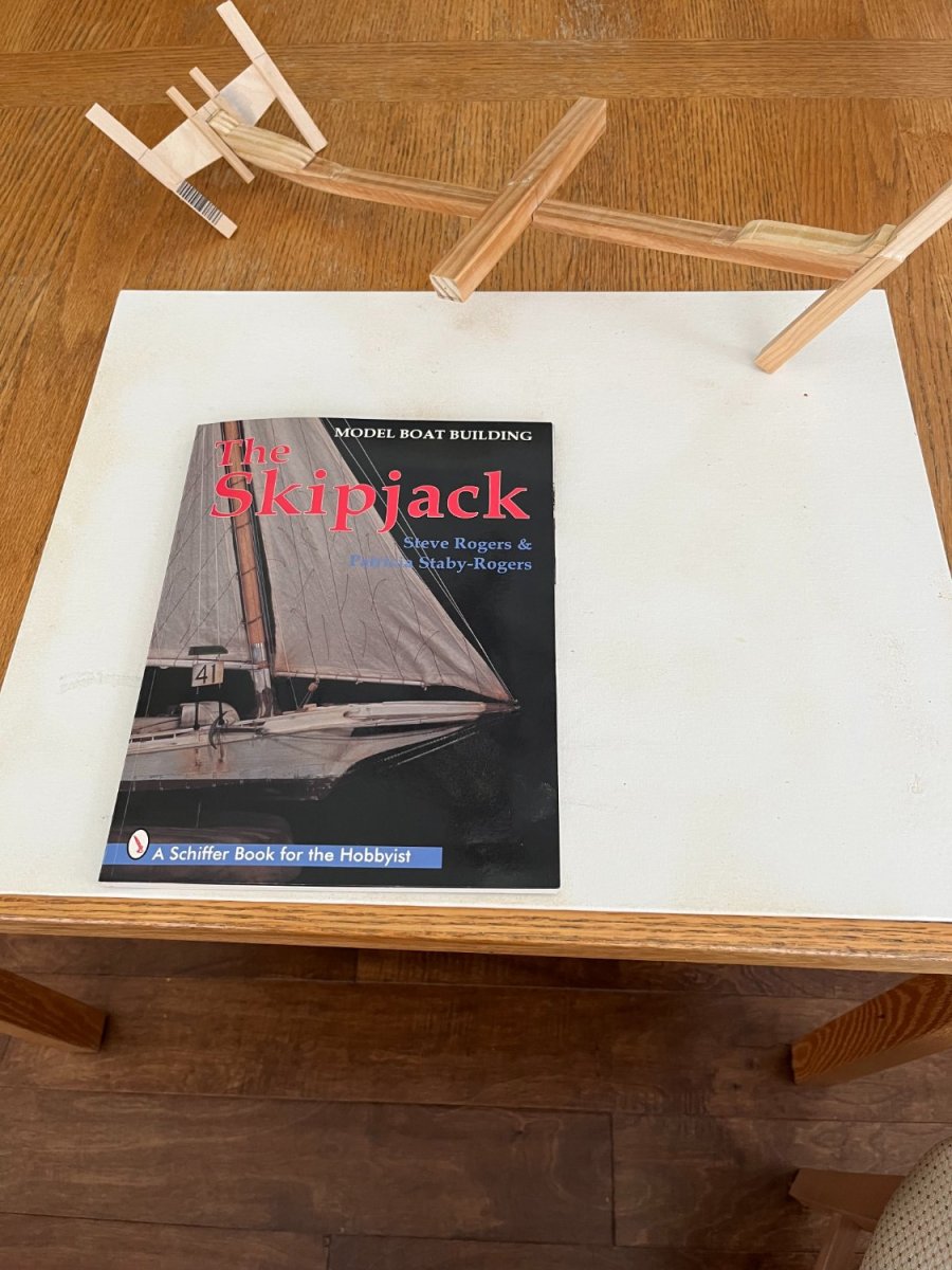
Here is my first attempt to attach pictures with comments. It looks like it worked, so onward with comments. This is a picture of the cover of the booklet with building instructions. Authors are Steve Rogers and Patricia Staby-Rogers. The instructions and pictures are quite clear, but as always, I have read and re-read the booklet as I progress through the steps. Occasionally, I have found something slightly out of order, but not enough to cause too much angst. I am attempting to follow the build instructions without much deviation. Unfortunately, I didn't take pictures of the very first steps in construting the keelson. The keelson is made by diagonally cutting a 1/2" X 1/2" strip, and glueing the reversed cut pieces to form the beginning of an upward curve from mid-ship toward the stern. Using ship curves, the angular pieces are faired to a smooth curve. A strongback is added to allow spreading the bulwarks. The transom and stem linerr were attached based upon the suggested angels off the keelson. It is suggested to add knees to the transom and stern post for strength and stability. The plans called for using 1/2" X 1/2" bass strip for the keelson, but I found on my first attempt when attrmpting to attach the bulwarks, the keelson twisted - thus, I used a 3/4" x 3/4" pine strip. This model does not use narrow planks for the boat sides. Instead, the sides of the boat, from the chine up, is constucted with 1 1/2" x 3/32" boards - think plywood instead of planks. More on this later.

-
I have been interested in models for a long time, even bagan working on some from time to time. Too complicated, too much life interfering with the build process, too much frustration. I actually belonged to the NRG and the Ship Model Society of NJ for a number of years, but little model production. Now retired and relocated to coastal North Carolina and began tinkering with various wood related projects and occasionally looking at the box of wood brought from NJ, including a couple of incomplete models. I had begun a Spritsail skiff a long time ago, using Steve Rogers & Patricia Staby-Rogers plans and reopened the project a year or so ago. Everything is almost complete, waiting for me to create a base and tie, no pun intended, everything together. That leads to this project,, the Skipjack. Some years ago, I visited St Michael's on the Eastern Shore of Maryland, and took a short sail on one of the remaining skipjacks on the Chesapeake Bay. Beautiful work boats! Thus, I began thinking about a model, again using the Roger's plans. Also, I came across Wye River Models, a small model supplier located on the Eastern Shore, near Annapolis. I bought the "box of sticks" which included the Roger's plans. By the way, a Model Ship World member, "Shore thing", created a build log and used the same supplier and plans. A much more advanced builder than me, he built a beautiful model and completed an amazing log. I won't attempt to be as prolific as Shore thing, but will use his advise on my build. A couple of observations before I begin the log process. BTW, if anypone has more accurate information than me on the history, etc., of Skipjacks.. please feel free to comments. Skipjacks were used primarily ro dredge oysters on the Chesapeake, using sail as the method moving from place to place. One mast, shallow draft, wide beam to handle the loads. As the oysters became fewer, so the boats, until only a few still exist. With the advent of the gasoline engine, retaining the requirement the actual dredging must be done only under sail, small pusher boats with engines were introduced. These small yawls only pushsd the boats to a point where sails were raised for the oyster collection process. No two boats were the same, mostly about 40 feet in length. thus, my model will not be a replica of an existing boat, but merely a representation of what one may have looked like. To that point, the Wye River plans are to scale to themsevels, but not to the Rogers plans. I will provide comments on the build progresses. Pictures will be added shortly. The process begins! Thanks for your attention and hopefully your help as I begin thsi endeavor. Dennis
-
Hi Quincy, Where are you in NC? I recently relocated from NJ to the Coastal (Southport) NC area and would like to see if we could find some folks in the area who would like to meet periodically. I believe there is a club in the New Bern area, but that's a haul from here. Hopefully you are closer. Let me know your thoughts, or if anyone else knows of a group in this area. Thanks Dennis Powell Bolivia, NC
-
Roger B Taney, a revenue cutter, was produced as a solid hull by Model Shipways when it was still located in NJ. I presume the time period when it was available was around 1976. It came in the traditional yellow box. I haven't seen it anywhere on the internet, so have to presume it is not available anymore. Good luck! Dennis
-
Pinnace Builders, I am at the point of fashioning the garboards. Here is what I think I know: The forward most end of the garboard should only be slightly forward of the edge of the scarf joint. It appears the plank tapers at the bow, but for the most part lays flat, conforming to the shape of the bottom of bulkheads as it approaches the stern. As it approaches the stern, there is a dramatic twist so that it eventually lays against the false keel. My question involves the taper at the stem. It looks like the taper is short, only 1/2 to 3/4 inch from the beginning to the point. Does the taper shaving occur on the keel side (bottom) of the plank and the plank is then bent down into the rabbit? Shaving on the bottom means the top edge will be "straight" to accept the next higher strake, which probably would be shaved consistently on the bottom. Or, is the taper shaving on the top? Shaving at the top would mean the next higher stake would also be shaved on the top? Obviously, all other planks are tapered into the stem. Thanks Tarawa03
-
Thanks. Tarawa03
-
Hi Chuck or anyone else working on the Pinnace, Another question - Do the planks have to be beveled? I looked at the Pinnace and the Longboat instructions, but there aren't any comments about beveling. From what I can see, it appears beveling is necessary. Help? Thanks Tarawa03
-
Thanks Chuck. I'll probably have some more questions by the time we meet on Saturday. Best regards, Tarawa03
-
I am not new to the desire to participate in the ship modeling experience, but have never completed anything! Some of my excuses are lack of time and frustration because I lack some of the skills (my fault because I have had the opportunity to ask questions, but haven't). I have about ten funny shaped objects in the basement, which are only identifiable by the nearby box and my knowledge of what they were supposed to resemble when completed. However each attempt has given me more confidence and skills and hopefully gets me closer to attempting and completing something. Enough of my self pity. Over the past few years, I was part of the group build of the Hannah with the Ship Model Society of New Jersey. Great experience, but still not completed. Some day! I'm in the process of building the Pinnace as part of the New Jersey Ship Model Society group build. Since this is my first planking experience, a question (or maybe more). Please excuse my lack of correct terms. All of the bulkheads are installed and faired. The first plank, along the sheer, has been bent and appears to fit the lines of the bulkheads and conforms to the sheer. Obviously, I have to install one side of the sheer plank (port) before the other side (starboard) can be installed. What mechanism/clamp can I use to keep the stem edge of the sheer plank correctly and firmly in the rabbit while the tail of the sheer plank is bent around the side? I presume once I get the sheer plank in place, I can use small spring clamps to hold the sheer plank to the bulkheads until the glue dries. Is the correct, or more appropriately, does my question make sense? Thanks Tarawa03