


gsdpic
-
Posts
849 -
Joined
-
Last visited
4 Followers


About gsdpic

Recent Profile Visitors


-
 Old Collingwood reacted to a post in a topic:
1960 Corvette by gsdpic - MFH - 1/12 - Multimedia
Old Collingwood reacted to a post in a topic:
1960 Corvette by gsdpic - MFH - 1/12 - Multimedia
-
Old Collingwood reacted to a post in a topic:
1960 Corvette by gsdpic - MFH - 1/12 - Multimedia
-
gsdpic reacted to a post in a topic:
SS Klondike II by John Ruy - 1/8” = 1’ (1/96 scale) - Sternwheeler Riverboat
-
Ryland Craze reacted to a post in a topic:
1960 Corvette by gsdpic - MFH - 1/12 - Multimedia
-
gsdpic reacted to a post in a topic:
HMS Indefatigable 1794 by Mowzer - Vanguard Models - 1:64
-
gsdpic reacted to a post in a topic:
HMS Indefatigable 1794 by Mowzer - Vanguard Models - 1:64
-
gsdpic reacted to a post in a topic:
HMS Indefatigable 1794 by Mowzer - Vanguard Models - 1:64
-
gsdpic reacted to a post in a topic:
HMS Indefatigable 1794 by Mowzer - Vanguard Models - 1:64
-
gsdpic reacted to a post in a topic:
HMS Indefatigable 1794 by Mowzer - Vanguard Models - 1:64
-
gsdpic reacted to a post in a topic:
HMS Indefatigable 1794 by Mowzer - Vanguard Models - 1:64
-
gsdpic reacted to a post in a topic:
1960 Corvette by gsdpic - MFH - 1/12 - Multimedia
-
1960 Corvette by gsdpic - MFH - 1/12 - Multimedia
gsdpic replied to gsdpic's topic in Non-ship/categorised builds
Right, finding and deciding on solder was a challenge. Some of the videos of soldering white metal kits show solder with a melting point of 70C or 100C (158F or 212F). I googled and found one or two US-based online stores that listed something like that on their web site but all showed out of stock at the time. But I now see one that has the 100C stuff in stock: https://ironplanethobbies.com/product/dccconcepts-sapphire-100-low-temperature-solder-dcs-s100 Instead I bought something else I saw recommended, Muggy Weld Super Alloy 1. I bought the smallest quantity I could find which seems to only be on amazon, not on their web site....four 18" sticks for 60 bucks. It is supposed to melt at 177C/350F. So, we'll see how that goes. I might be setting myself up for regret, but it seems a bit nuts to glue everything together with CA then dunk it in an acetone bath. And I don't particularly want to deal with buckets of acetone. As for epoxy....I know a lot of people hate CA but I'd much rather use it than epoxy. Once I get the stuff, I will try it out first on that same front license plate bracket, which has just three parts. I suspect I will wish I had some better clamping solution for holding the parts while I solder. At least the frame parts that I plan to primarily use it on are fairly large. I'd be a lot more leery of using it on small or thin parts, like the tubular chassis of a race car. If it does not work for me, maybe I'll try the 100C stuff from the link above. -
gsdpic reacted to a post in a topic:
1960 Corvette by gsdpic - MFH - 1/12 - Multimedia
-
Canute reacted to a post in a topic:
1960 Corvette by gsdpic - MFH - 1/12 - Multimedia
-
CDW reacted to a post in a topic:
1960 Corvette by gsdpic - MFH - 1/12 - Multimedia
-
Paul Le Wol reacted to a post in a topic:
Muscongus Bay Lobster Smack by JacquesCousteau - Model Shipways - 1:32 - Rescaled and Modified
-
robert952 reacted to a post in a topic:
Muscongus Bay Lobster Smack by JacquesCousteau - Model Shipways - 1:32 - Rescaled and Modified
-
yvesvidal reacted to a post in a topic:
1960 Corvette by gsdpic - MFH - 1/12 - Multimedia
-
Egilman reacted to a post in a topic:
1960 Corvette by gsdpic - MFH - 1/12 - Multimedia
-
Keith Black reacted to a post in a topic:
Muscongus Bay Lobster Smack by JacquesCousteau - Model Shipways - 1:32 - Rescaled and Modified
-
1960 Corvette by gsdpic - MFH - 1/12 - Multimedia
gsdpic replied to gsdpic's topic in Non-ship/categorised builds
Melt Test I received the new soldering station, though have not yet received the solder. The key feature is the ability to set the temperature, so I did a little "melt test" on the kit supplied white metal. I grabbed one of the three parts of the front license plate bracket. I've already commented that I might not put that bracket on so I figured it was a good piece to use for my tests. I started with the soldering iron at 350 degrees F, which is about the melting point of the solder. I then held the tip of the soldering iron to the bracket and fortunately nothing happened. From there, I bumped up the temperature by 10 degrees and tried again, repeating that process until something happened. The first sign of any melting was at 430, but that was very minor. Even up to 475, the melting was minor and slow. That is as high as I went. So seems like I have 80 to 100 degrees to play with between the melting point of the solder and where the white metal parts might start to melt. The solder is supposed to arrive Tuesday. It is coming from the west coast so with any luck it will not be affected by the winter storm.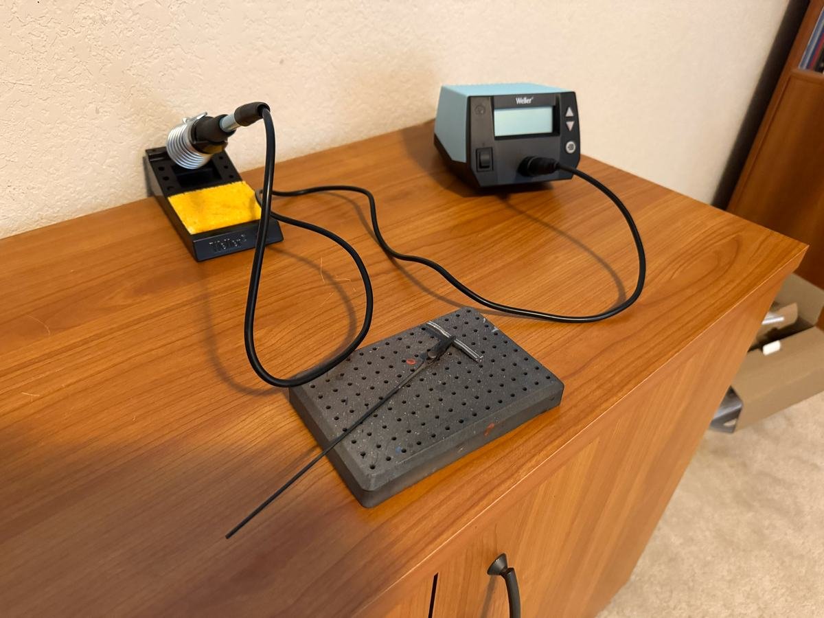
-
gsdpic reacted to a post in a topic:
Bentley Blower by RGL - Airfix - 1/12 - PLASTIC
-
Excellent planking and pump! I don't see many lapstrake boats here on MSW so that is a nice change of pace.
-
1960 Corvette by gsdpic - MFH - 1/12 - Multimedia
gsdpic replied to gsdpic's topic in Non-ship/categorised builds
Just a quick update that I ordered a better soldering iron and some solder that I will attempt to use on the frame. Meanwhile, all I've done is drill a few more holes. -
Congrats on the commission, Glen. Looks like another interesting and challenging project to follow. That bottle looks great but something tells me you would not have chosen it, if it was up to you. And I learned something....I never knew the origin of the word "speakeasy". I am not familiar with City Post. I have been up to Georgetown plenty of times, though about the only time I've been downtown was when I was called for jury duty. I live in Wilco even though I have an Austin address.
-
1960 Corvette by gsdpic - MFH - 1/12 - Multimedia
gsdpic replied to gsdpic's topic in Non-ship/categorised builds
And I am prepping for the next step, step 4. That is one of the larger steps with the most parts, to build the frame. You can see below that each of the two frame rails are built up from 6 separate pieces. The pieces require at least a bit of massaging to get them to fit together perfectly. The fit is pretty good as is but I think it can be made better. In the upper right corner you can see some of the various cross braces for the built up frame. I am tempted to try soldering the frame pieces, and have done some research regarding that. I've done a small amount of electrical soldering in the past but would definitely say I am no more than a beginner. I found a youtube video specifically about soldering MFH kits but I have not been able to find the type of low temperature solder that he used, at least not in hobby quantities. Virtually all of the parts in this step end up painted semi-gloss black. I will likely build it all and then paint it as a unit. One nice thing....the instructions actually have a full size schematic drawing of the completed frame which should help to ensure that everything is together properly and straight and square.

-
1960 Corvette by gsdpic - MFH - 1/12 - Multimedia
gsdpic replied to gsdpic's topic in Non-ship/categorised builds
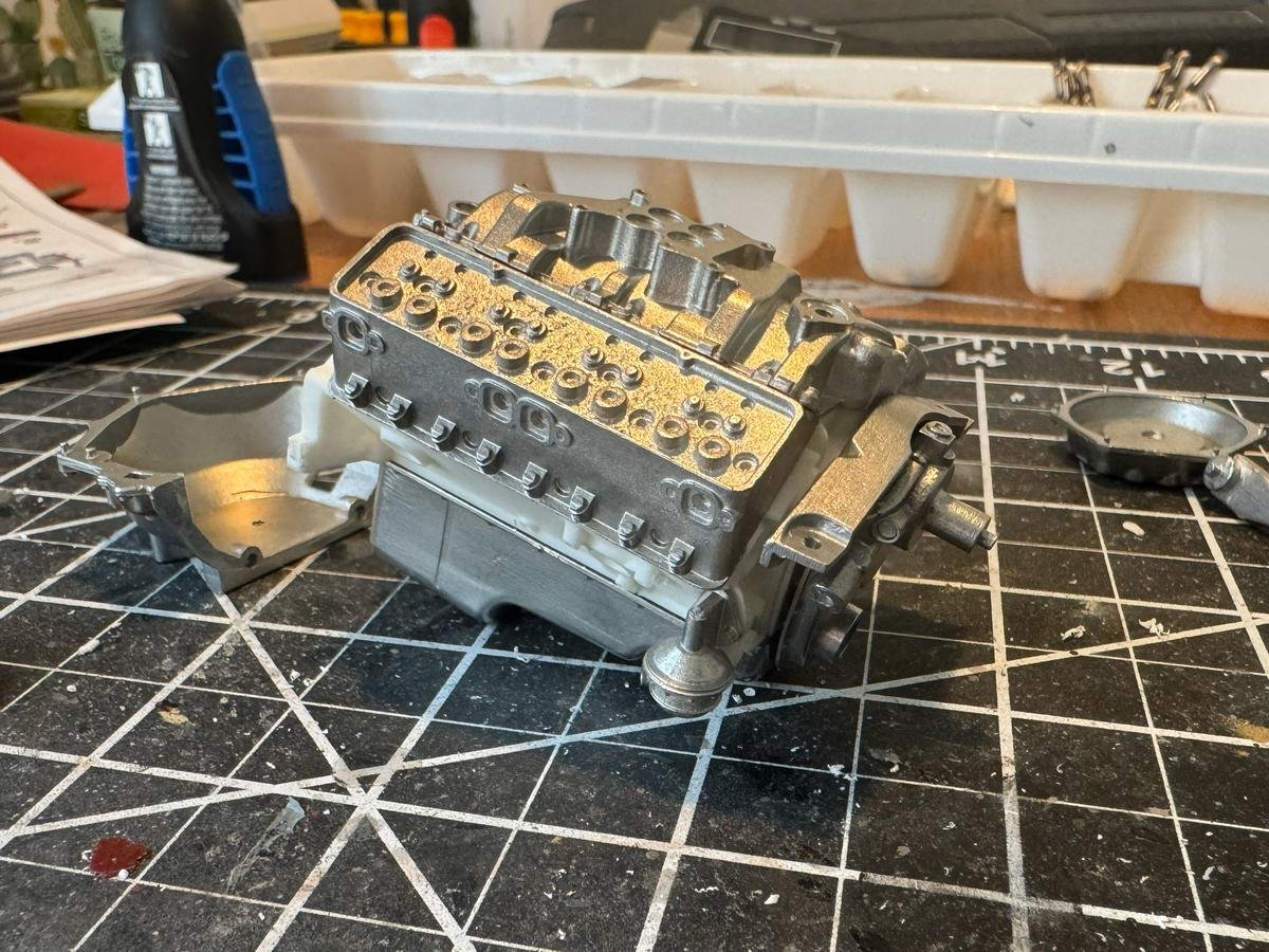
And just like that, steps 1, 2, and 3 are done, completing the engine. It is certainly not the most detailed MFH engine, but I think it looks pretty good. Of course in the prototype, the plug wires are hidden in that chrome shroud above and around the engine, so that hides one of the most obvious details one could add. The rest of the engine went together fairly well, though the fitting of that shroud and the distributor were a bit bothersome. Of course there were more holes to drill that I missed the first time around, but fortunately they were all accessible. I know they say to pre-build these things first to catch such issues but I just don't see how that is possible. I may attempt to add a few more details, but likely only after the engine is mounted on the frame and the firewall and fender liners are in place, or perhaps as I am doing those steps. In these pictures, the air cleaner is just pushed on, not glued, so it can be removed to provide better access to add details. e.g. the real engine has the throttle linkage on the left side of the carb, heading back to the firewall, under the plug wire shroud. The bell housing was stripped and painted with alclad aluminum, per egilman. The transmission and exhausts were painted with alclad steel, which I find to be far too dark, so I started with a very thin coat of steel over the metal, then misted over some aluminum as well. The instructions suggest painting the valve covers silver but I just left them as is, with a little polishing and clear coat.


-
1960 Corvette by gsdpic - MFH - 1/12 - Multimedia
gsdpic replied to gsdpic's topic in Non-ship/categorised builds
Thanks @DocRob that looks like a great idea. -
1960 Corvette by gsdpic - MFH - 1/12 - Multimedia
gsdpic replied to gsdpic's topic in Non-ship/categorised builds
Oh man, thanks. The various car auction houses' web sites can be a gold mine of pictures but I could also drive myself crazy looking at those pictures during the build. This particular detail was a bit tough to find, though they often have pictures of the underside of the car. On several cars, it appears that the lower part attached to the bottom of the bell housing was painted orange but I never saw one where it appeared the main part of the bell housing was painted. It was often hard to see, and not a lot of light up there, but it clearly was not orange, so you are correct. And I double checked, the MFH instructions did call out red for that part, so I was just going based on that. -
1960 Corvette by gsdpic - MFH - 1/12 - Multimedia
gsdpic replied to gsdpic's topic in Non-ship/categorised builds
Thanks all for the likes and the hints and the good discussion. The orange parts are looking pretty good. But, I probably really should have used the pink primer instead of the gray primer for parts being painted orange, but I did not think of that until too late. I may do one more coat of orange after these cure a bit more. Then might do some highlighting and detail painting. A couple other unanticipated obstacles.... - the partially assembled engine with 5 metal parts is actually quite heavy. I don't have a small scale but I would say 6 ounces or so. My usual methods for holding parts while being airbrushed do not handle such heavy items so well. - I also just realized that my airbrush spray booth is just barely big enough to contain the main body part of this kit. I have used it on 1/12th scale F1 cars but they did not have any single part nearly as large as the body of the corvette. It would be disaster to bump the inside of the booth with freshly painted body parts. I might invest in a larger, better spray booth, as I have a couple other 1/12th scale cars in my stash and even a couple of 1/8th scale Pocher cars, so there will be more times in the future that I need a larger booth.
-
1960 Corvette by gsdpic - MFH - 1/12 - Multimedia
gsdpic replied to gsdpic's topic in Non-ship/categorised builds
Yea, I bought mine at least a year ago too. It was one of the few MFH kits that I have seen that did not sell out right away, though I've only been aware of MFH for a few years. It is definitely a little different experience with all the metal parts and with the size of the body. I hope I can do it justice. -
1960 Corvette by gsdpic - MFH - 1/12 - Multimedia
gsdpic replied to gsdpic's topic in Non-ship/categorised builds
Craig....that's close to what I found though the reference I read said that the 245hp engine had dual carbs but same compression. The 270hp engine was the one with higher compression and mechanical valve lifters instead of hydraulic. Though the references I found were text paragraphs, not nice tables like you had so maybe I misinterpreted the text. But yes they were all variations of the 283 cubic inch engine. I recall also reading somewhere but not sure where now, that only the base engine had the intake manifold painted orange, the others were bare metal/silver. -
1960 Corvette by gsdpic - MFH - 1/12 - Multimedia
gsdpic replied to gsdpic's topic in Non-ship/categorised builds
Thanks for the comment, Egilman, and glad to have you following along. While you can never trust pictures on the internet, or the color calibration of the recording device or monitor (tho my monitor is calibrated thanks to the photography I do), the engine color to me definitely appears orange. Yes, it is a very reddish orange, but still I would call it orange, not red. For example, this youtube video of a supposed barn find 1960 corvette shows the engine with an orange tint. If that truly is a barn find, then I presume that is original color. Regardless, while buying the paint for the body I also added a bottle of "chevrolet engine orange" to my cart, so I will use that. Oddly, from my research, it also appears that MFH replicated the least powerful of four engines that were available in 1960, the base engine with the single 4 barrel carburetor, which appears to be shown in this video. Anyway....here's the kit engine with some parts glued up and primed with grey primer from scalefinishes.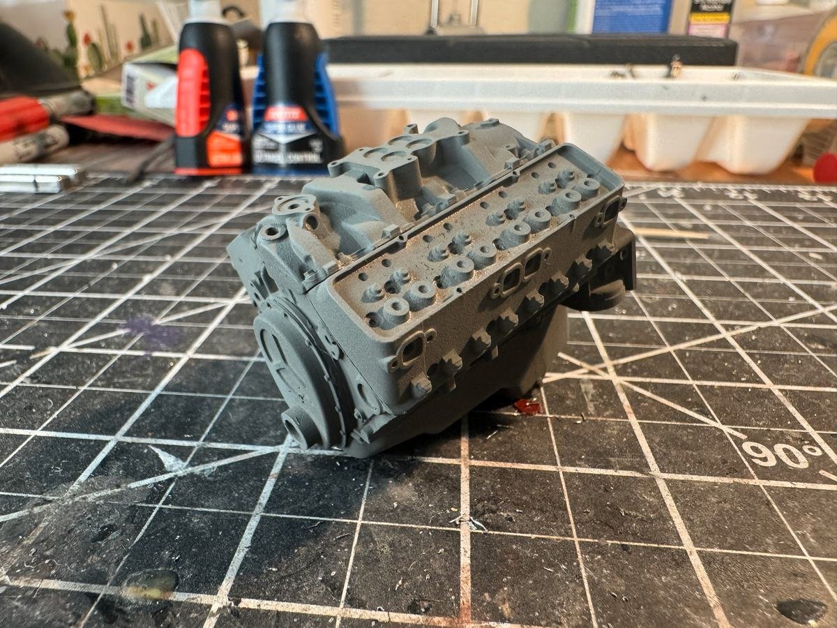
-
1960 Corvette by gsdpic - MFH - 1/12 - Multimedia
gsdpic replied to gsdpic's topic in Non-ship/categorised builds
As you can see here, I've finished my prior project, a 1931 Rolls Royce coupe based on the old kit from Monogram (and yes I fixed the passenger side mirror that I knocked askew during the photo shoot). I then cleaned the hobby table and got started on the Corvette. Here is a picture of most of the "part 1" engine pieces just stuck together, no glue yet. Getting to that point required drilling out quite a few holes, as the holes in the resin engine block for the alignment pins in the metal parts were generally not deep enough and in some cases not wide enough or not spaced correctly. And I have more to drill....the valve covers are attached to the cylinder heads with 4 "rivets" each, and those holes all need to be drilled in both the valve covers and the cylinder heads. My first impressions of the kit from going through all the parts and organizing things were great but I have to say my second impressions are a bit less positive. It felt like the resin engine block was about 97% of the size it needed to be. The pins on the back of the cylinder head were 38mm apart but the holes in the block were about 37.25mm apart. Likewise, the front of the oil pan hung over the front of the engine block by a tiny amount, causing the front cover to not fit well. I glued a 1/32" square styrene strip as a sort of gasket for that front cover to get it to line up with the oil pan. And then there is the incorrect paint call out: the instructions specify red for the engine block but in 1960, GM used orange for its engine blocks. And, as for the "rivets", the instruction sheet says I have 22 "rivet-S" and 14 "rivet-L". The S and L might mean short and long or maybe small and large, who knows. All I know is that I have 36 identical rivets. Other things I have learned so far.... - as others have said, it is important to have a good pin vise and many bits as you will be drilling a lot of holes. - it is also very useful to have a digital caliper handy to measure things - and handy to have a printed table showing the size in millimeters of the various drill bits, assuming you have a numbered set of drill bits (e.g. #50 to #80). With the above, I can use the caliper to measure the pin on the metal piece, then consult the table to find the best bit size to use, then put that bit into the pin vise and drill away. I have to do a bit more part clean up and hole drilling. I then plan to glue together most of the parts that are destined to be painted orange then prime and paint those parts.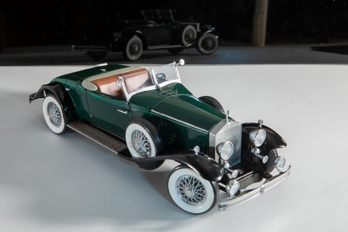
-
Nice, looks like good detail on the prints. I'll be interested in your experience with the paint. I recently bought my second Gaahleri airbrush and they threw in a free bottle of the Kaleido paint. I have not used it yet, mostly because I am not sure when I will want "Mint Green" paint. I've noticed a few youtube videos discussing this paint but have not taken the time to watch any yet.


