gsdpic
-
Posts
748 -
Joined
-
Last visited
Content Type
Profiles
Forums
Gallery
Events
Everything posted by gsdpic
-
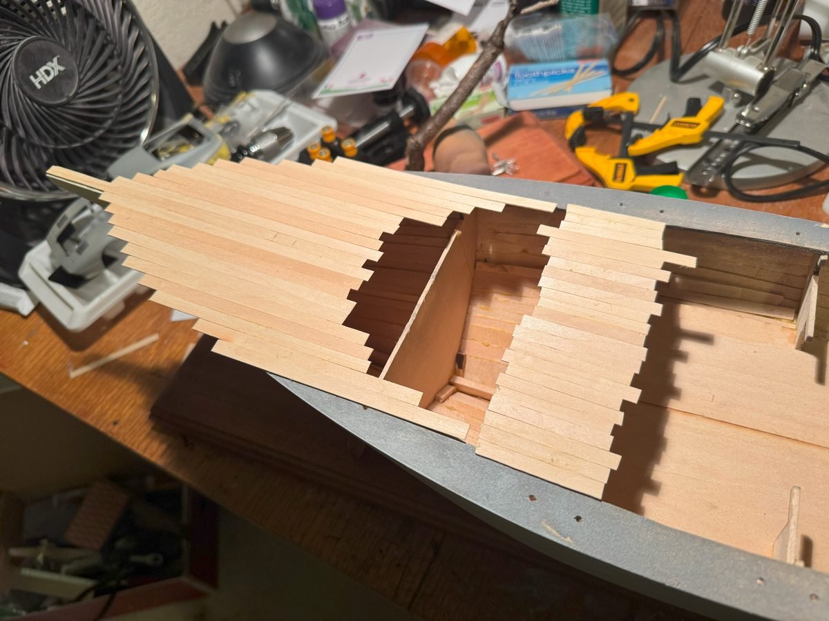
Thanks for the patience of those following along. Likely there will be another gap before my next post. Meanwhile, I've stained the deck and cockpit floor. As usual, the stain is a bit splotchy on the basswood but I can live with that. I've also started doing the vertical planking of the outside of the cabin and cockpit coaming. As you can see, I glue on the rough cut pieces and then trim off the tops to get things even. I'll do similar planking on the inside of the cockpit coaming and add a cap rail on the coaming and a roof over the cabin. And all of that will be painted white (with the possible exception of the roof). Have not decided what to do with the rest of the inside of the cockpit yet., e.g. the inside of the hull planks. I might just paint that area gray. Much of it will be hidden when I add the seats.
-
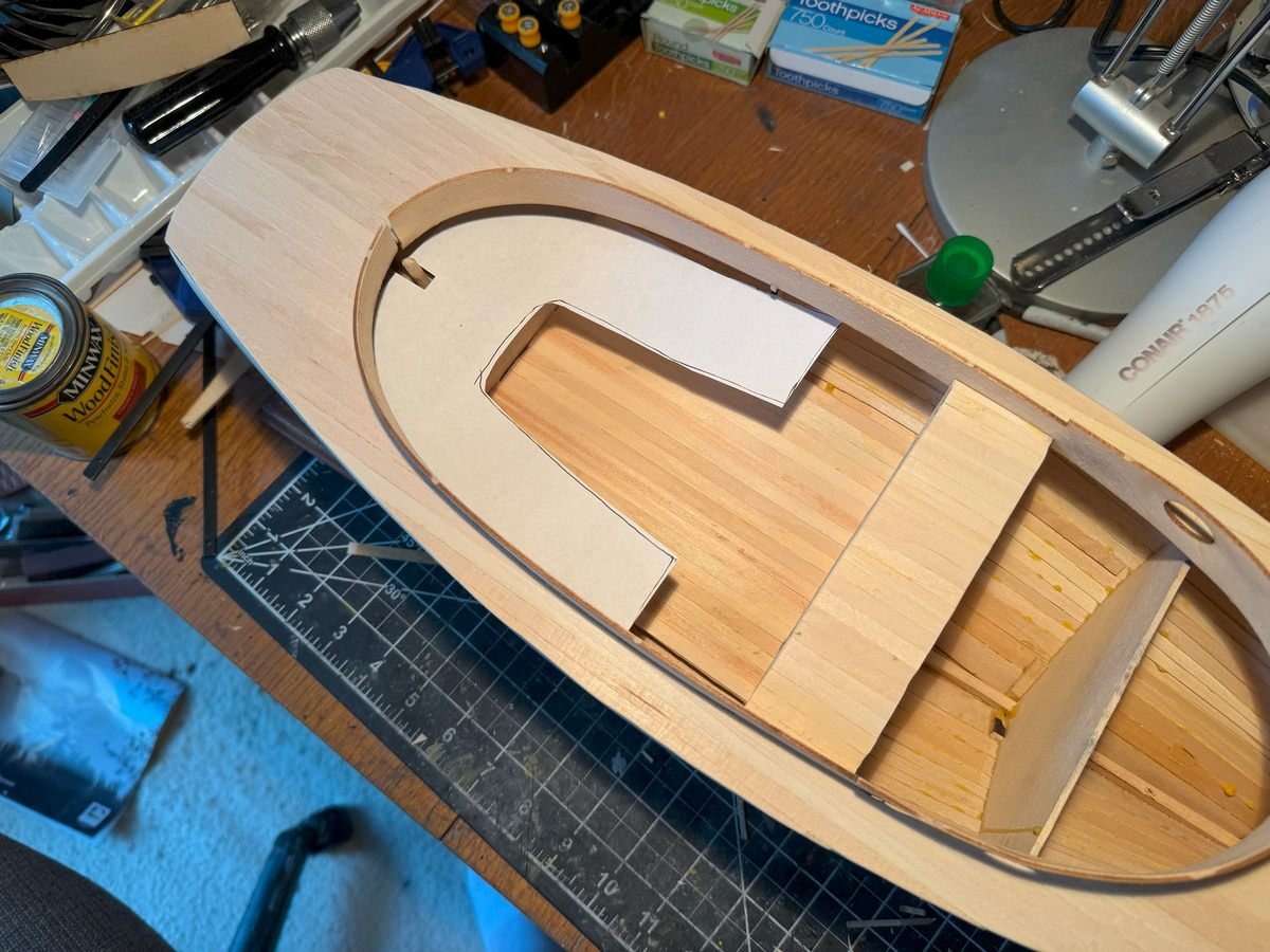
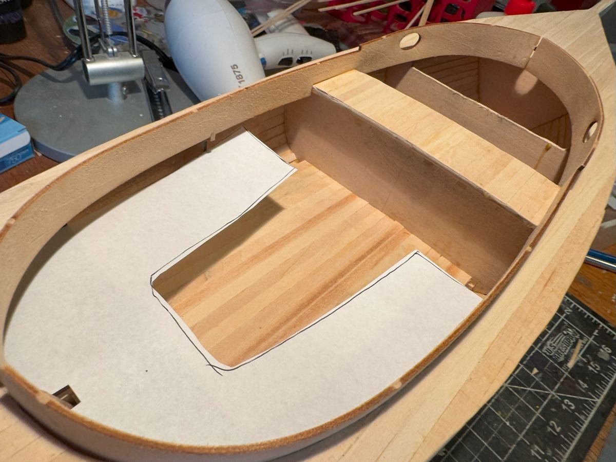
A little more progress.....I have planked the cockpit floor. I also did a paper template of the seat and test fit that. I have not decided what, if anything, to do with the bulkhead at the front of the cockpit. The kit instructions do not seem to address it....maybe plank it vertically or horizontally or just paint it. I've also dug out a couple old tins of stain and done a bit of testing to try to figure out which to use on the deck, cockpit floor, and seat. Though I am not yet sure.
-
I had to react with the open-mouthed "wow" emoji because that is exactly what I did in real life when I scrolled down and saw the picture. The body and decals look flawless. Thanks for the warning about the MFH decals.
-
Sopwith Camel by Spiff - Model Airways - 1/16
gsdpic replied to Spiff's topic in Non-ship/categorised builds
Looks like you've done some excellent work on the engine, prop, and wings. I have this kit on my "shelf of doom". I built the engine and prop then completely switched gears and built the Artesania Latina Sopwith Camel instead. That is disappointing about the wing tips....I dug my kit out and compared the ones I have to the plan and they are very similar to what yours looked like. -
Cool. I have not seen that before either. I am not any sort of admin or anything....but if you go to the "ignored users" section of your own profile, it lists the account names for which you've hidden the signature and you can unhide it there. I did not try the "hide all" option, but this works for hiding and unhiding an individual.
-
I've now glued in the cockpit coaming/cabin sides on both sides, as shown below. The instructions say to "plank" both sides of the cockpit coaming with vertical pieces of the same wood used for the deck. However, many of the completed builds of this kit that I have seen online seem to have skipped that step. I guess I will go ahead and do that planking.....if nothing else that will allow me to cover the gap I accidentally left in the back between the two sides of the coaming, as I trimmed one of the laser cut pieces just a bit too much. Doh.
-
Endeavour 1934 by Herbert Heger - 1:35
gsdpic replied to Herbert Heger's topic in Group Projects on Model Ship World
Also seems like this should be in the build log section not in the group build section..... -
Very well done! I am not much into military models but they do present a lot of opportunity for artistic/creative interpretation with the different liveries and the weathering. You've taken full advantage of that here with your expert weathering and accentuating the details.
-
Excellent as always! And good call on the moss.....it makes it look more like the wood is coming up out of the rock instead of just sitting on top of it.
- 106 replies
-
- 4
-

-

-
- Kentoshi-Sen
- bottle
- (and 1 more)
-
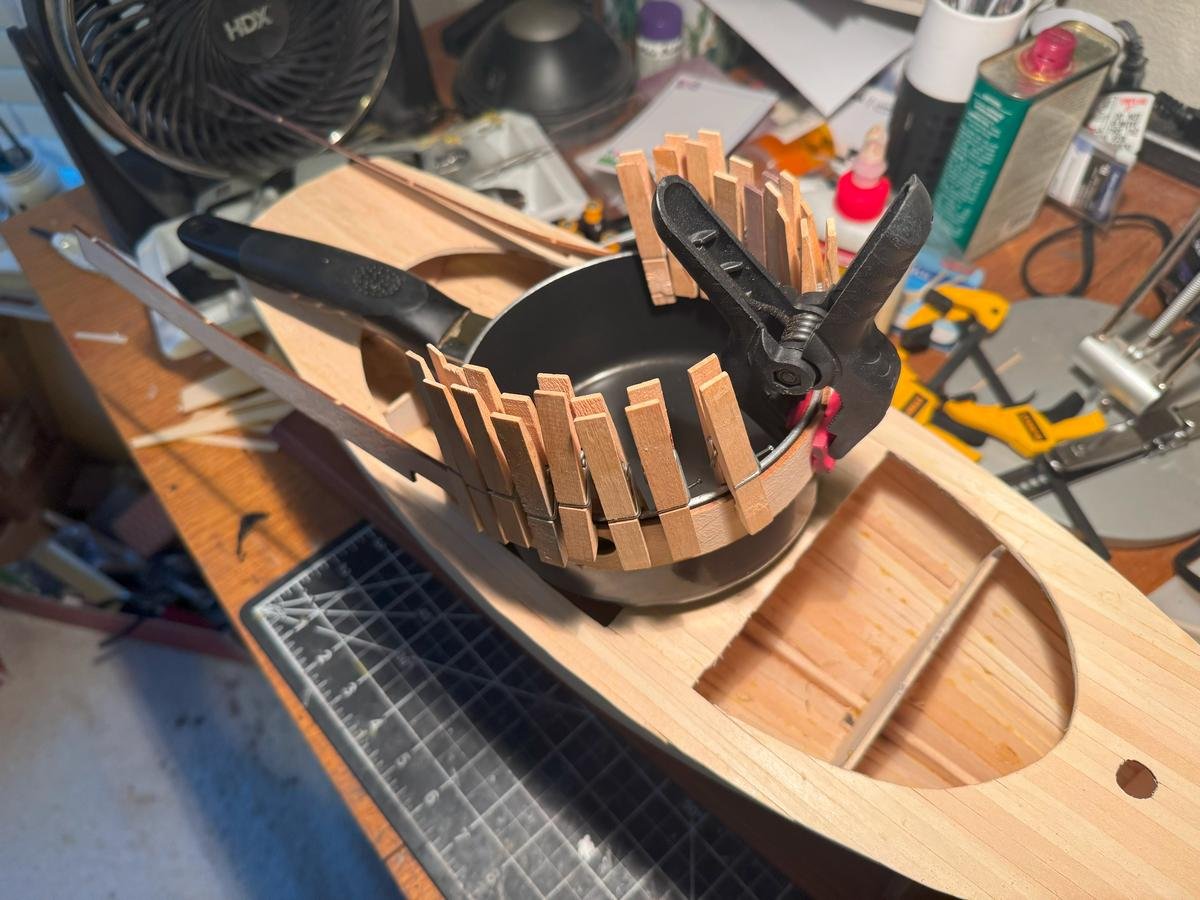
The cabin sides and cockpit coaming sides are two laser cut parts, one for each side of the boat. Here I am trying to bend the pieces. I first soaked the front half in hot water for a while (15-20 minutes) then carefully clamped it to a small sauce pan while also applying more heat with a hair dryer. The sauce pan is obviously not an exact match for the curve of the front of the cabin but it is a lot closer than a straight line. I'll probably let it dry over night then unclamp it and see what I have. Assuming it works I'll repeat the process for the other end of the pieces to accomplish the curve around the back of the cockpit.
-
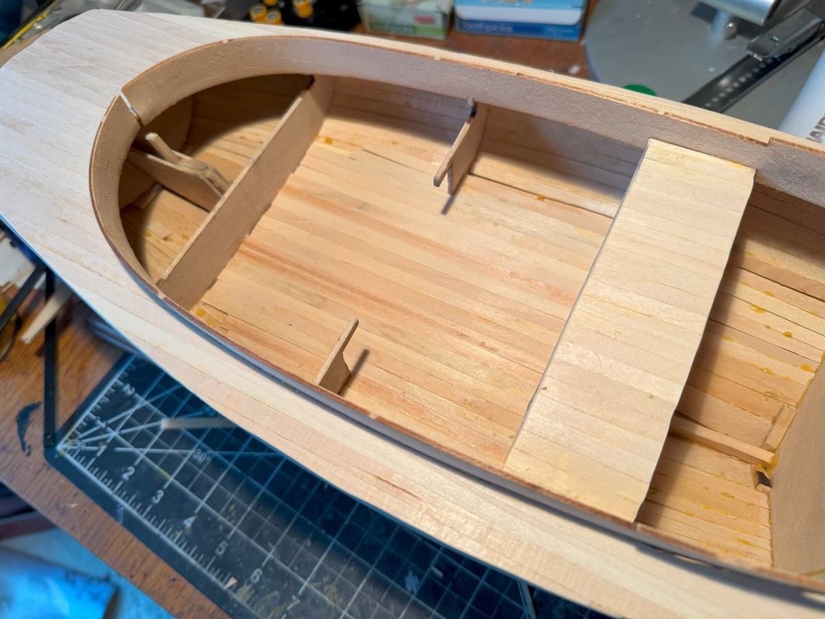
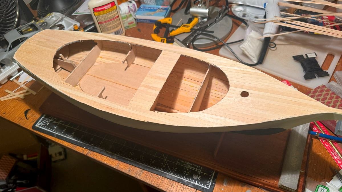
Another quick update. I've completed the deck planking and did a rough cut around the outside and inside edges. I did a little sanding of the outside edges but have more to do. Oh, I also cut out the hole for the mast as you can see.
-
Thanks Glen and Jacques for the comments/compliments. And yes it is a good size model. Even without the bowsprit in front and the gaff hanging off the back, the hull as shown is right at 2 feet long and about 7.5 inches across. I've begun the relatively quick job of planking the deck. Obviously everything will need to be trimmed up once I complete it and all the glue dries. As you can see, the planks in the front and middle section do not quite line up. For the middle section, I just cut one piece of wood into a bunch of approx 2 inch sections and that piece of basswood must have been ever so slightly less wide than average. But I don't think it will matter at all once I get the cockpit and coaming installed. I will likely just leave the deck natural, maybe add some wipe on poly for a bit of protection and smoothness. I do kind of struggle with this build. I sometimes think I should do x, y, and z to try to improve on the kit and add some details or whatever, then I look at my stash of car kits and think maybe I'd rather finish this and work on them. So for now I am sticking to straight out of the box.
-
Oh man, that looks good and I am jealous. I recently bought an FDM 3D printer (Anycubic Kobra 3) to get started with 3d printing but fully intend to also get a resin printer at some point as well. Seems they each have their own niche where they are useful. I figured an FDM printer was a better place to start since it seems like less hassle than resin, with no washing and curing needed.
-
Make that three votes for the second one. I feel like the Japanese garden base competes with SIB for attention. Either way, like Bob said, great work!
- 106 replies
-
- 5
-
-
-
- Kentoshi-Sen
- bottle
- (and 1 more)
-
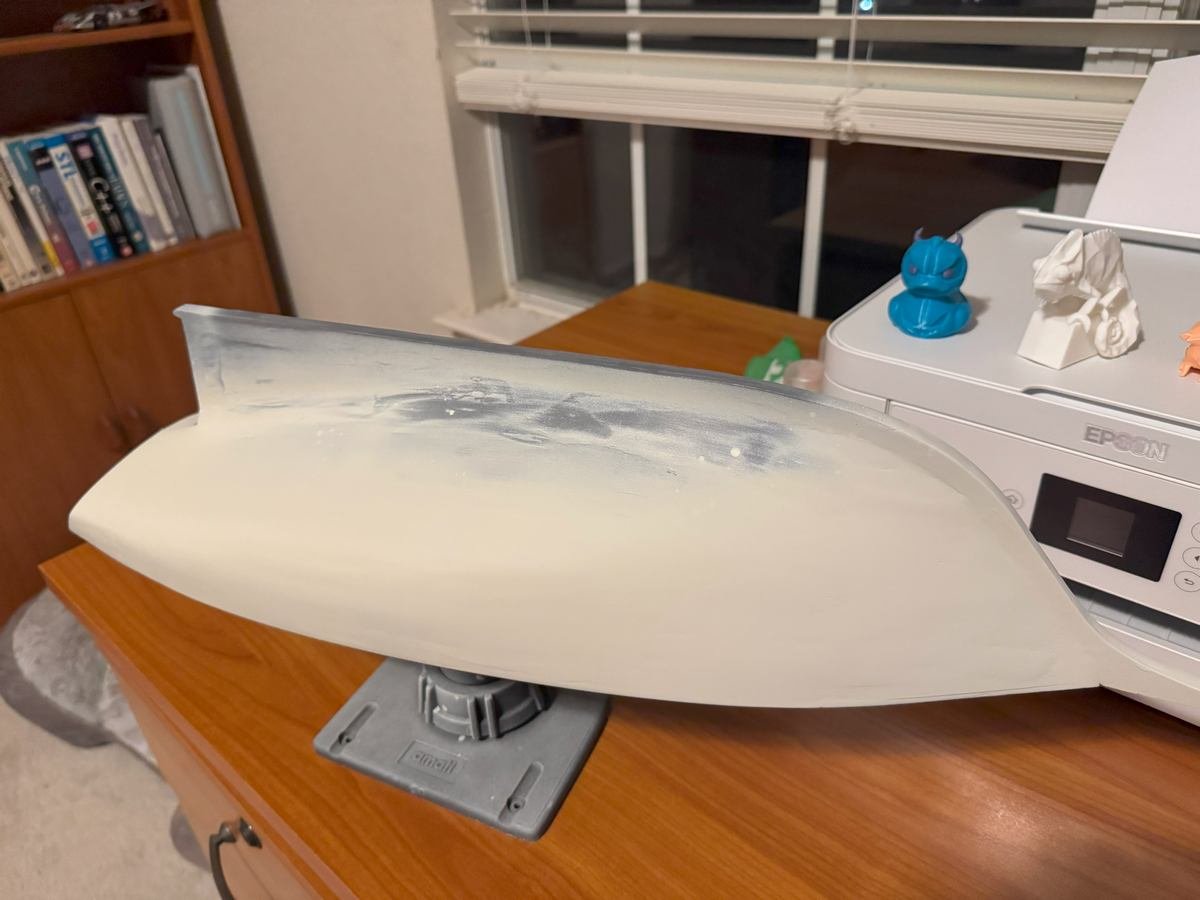
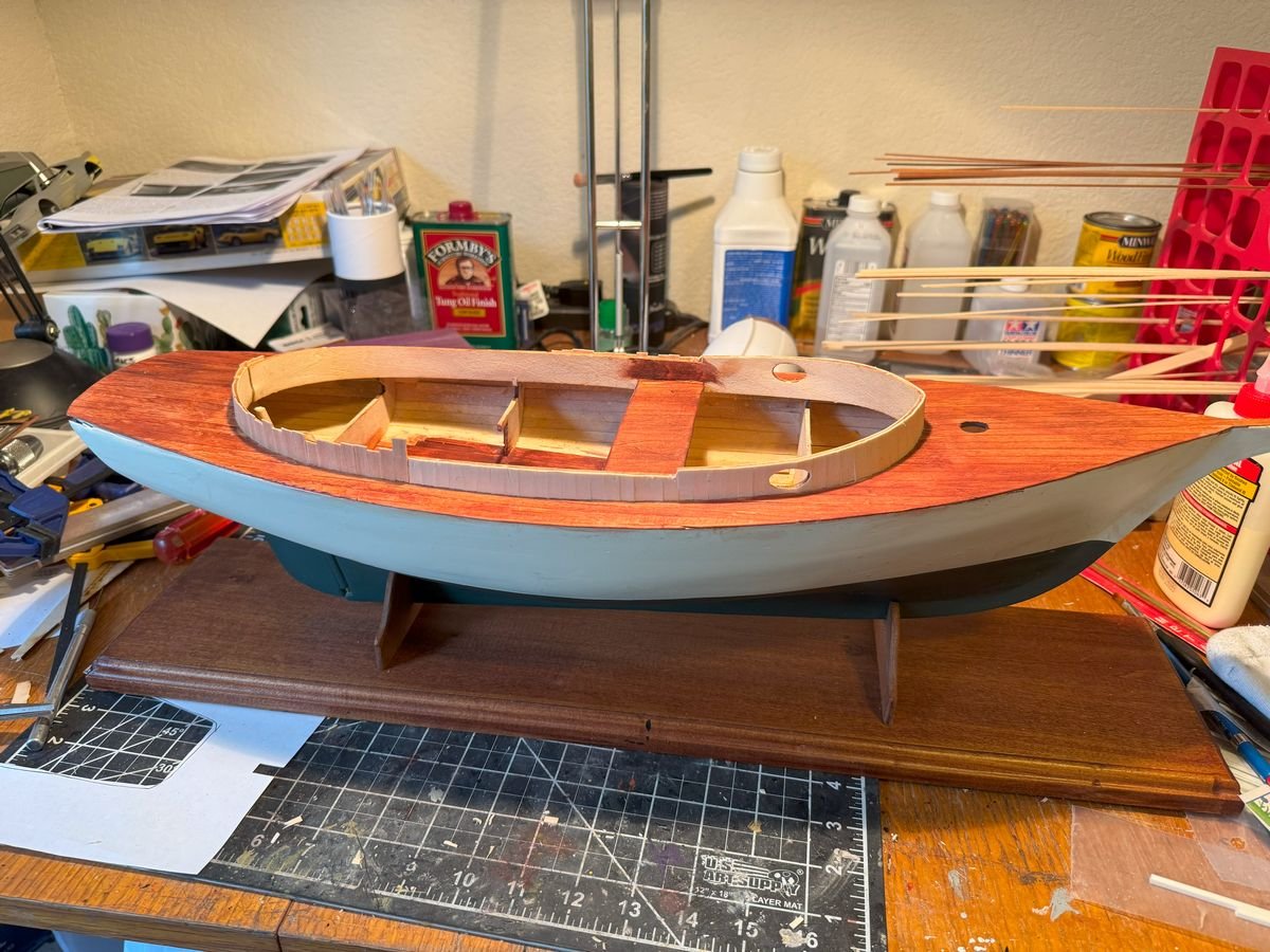
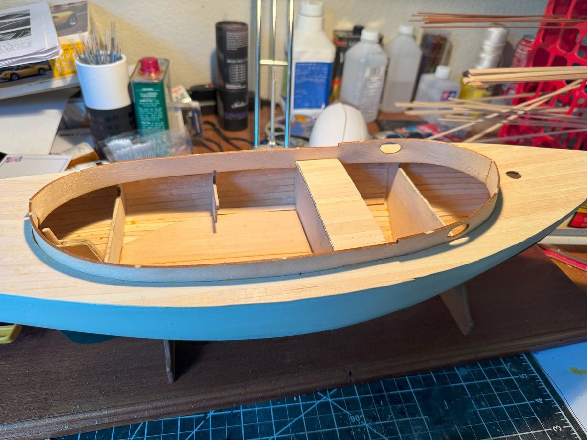
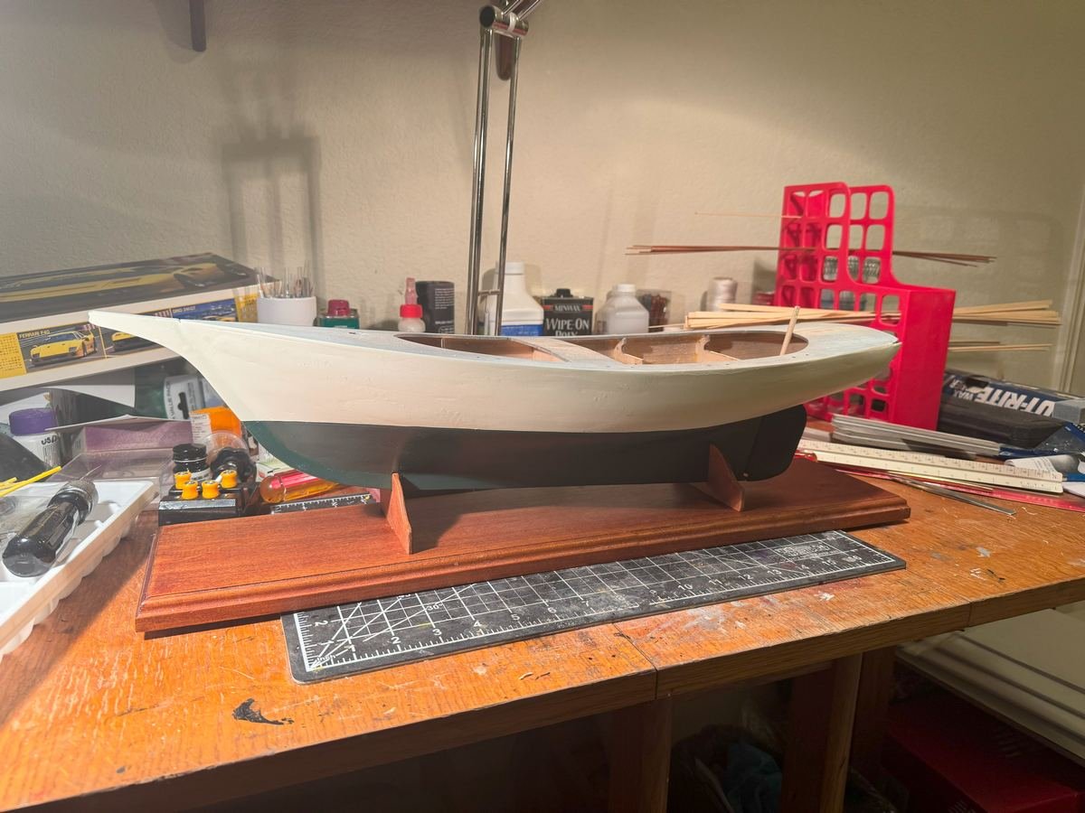
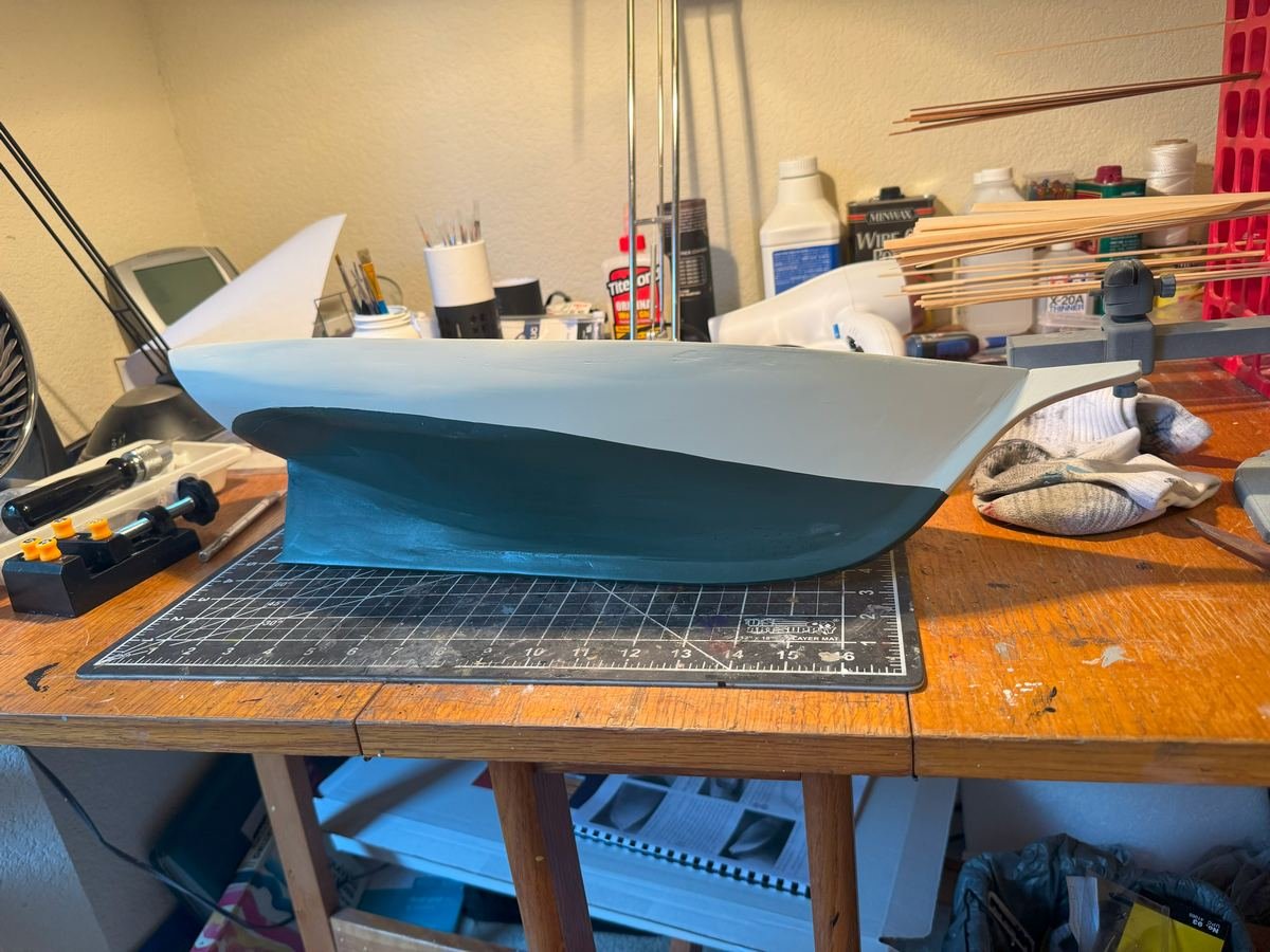
Ok, I have declared the hull painting done and I have mounted the hull to the baseboard. The baseboard is reused from an abandoned build of the model shipways Niagara. The cradles are included in the Friendship Sloop kit. They are laser cut mahogany which I sanded down a bit to round off the corners and finished with a tung oil finish. Pay no attention to the box in the back left corner of the table. That is definitely not another side project that I started 😁
-
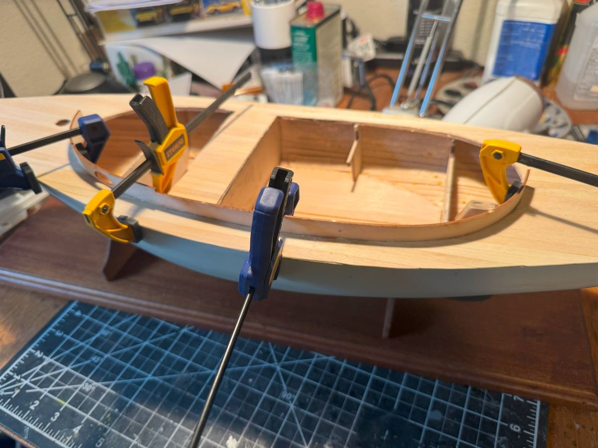
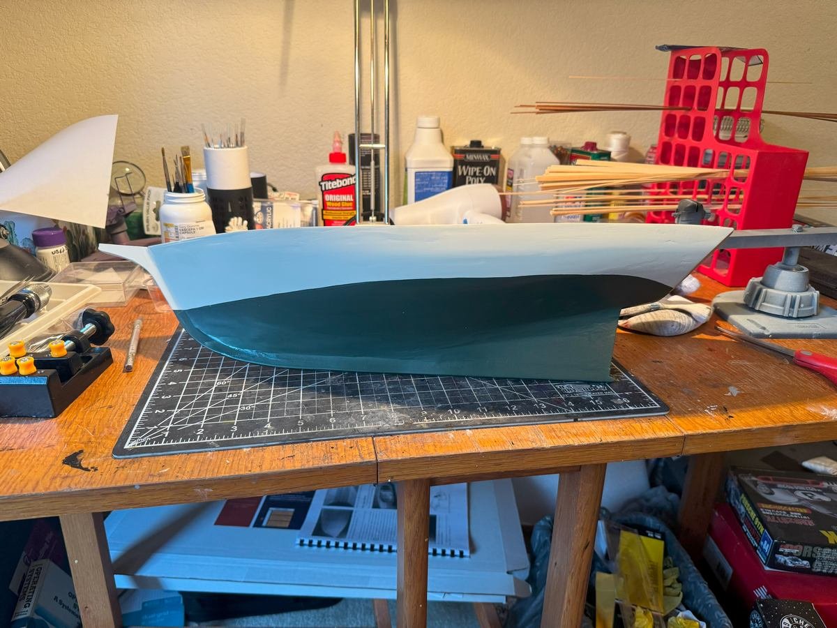
Thanks for the patience. I finished the other project I was working on (though as always, tempted to start another) and have been through several iterations of tape and paint, both green and off white. It was tricky to get a decent water line with the shape of the hull (and my technique, no doubt) but I think I am at the "as good as it's gonna get" stage. I'll likely still do a bit of light sanding at some point and then go over everything with a satin clear coat just to unify the finish. Both the green and offwhite are satin but still there are some variations in shininess.
-
That's interesting, and unfortunate. I thought the $800 de minimis exemption still applied for stuff from Canada but I guess at least some of what you ordered originated in China and so maybe the Chinese tariff rules applied instead of the Canadian ones. Did UPS provide a detailed breakdown of how they calculated the $61? I have an interest in this and am just trying to figure out how things work now, as there is a Canadian reseller that has a Model Factor Hiro kit (from Japan) that I am interested in. I've not ordered it primarily because of tariff uncertainty, though I have investigated a little bit and believe that the $800 de minimis exemption is still in place for both Canada and Japan.
-
When I built my AL Sopwith Camel, some of the pieces of the stand were missing. I filled in the "parts request" from their website and the parts showed up in the mail (to the United States) within a couple weeks. That was back in 2024. See post #77 in the log below. And here is the link to the parts request: https://artesanialatina.net/us/en/p/15-parts-request Just go to their main web page and scroll down to the bottom to see the link. That is what I used. I do now see that the instructions refer to a "national identity card or passport number" but I do not see any field in the form for that and did not have to provide any such thing when I made the request.
-
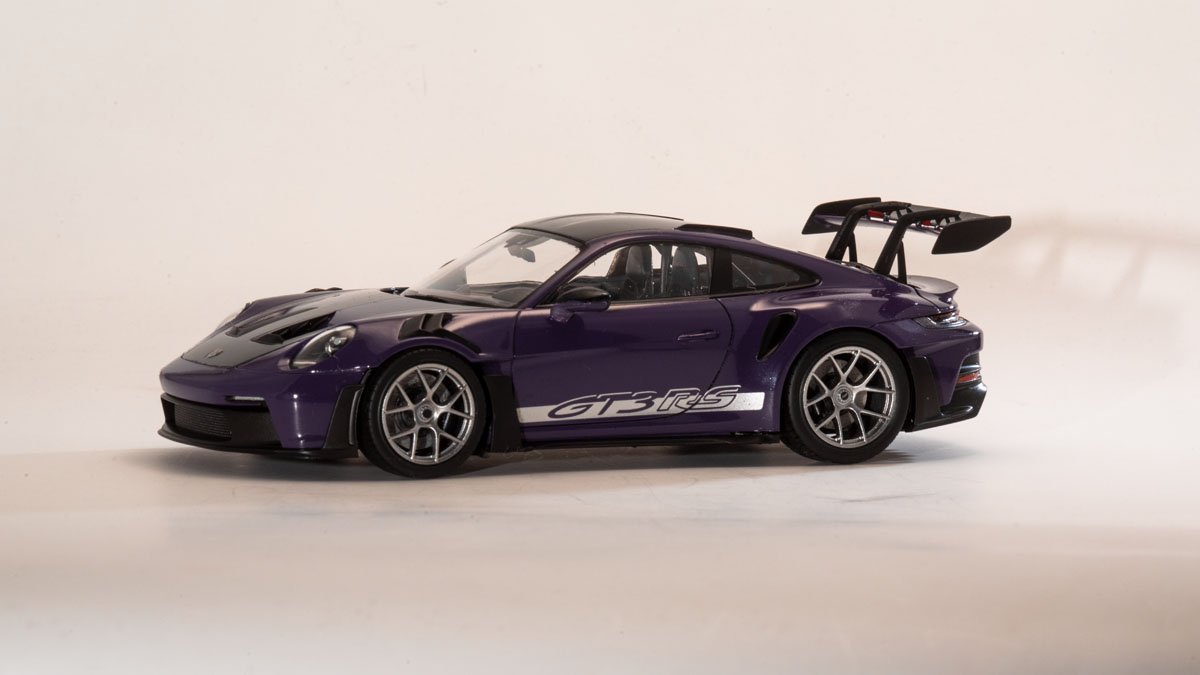
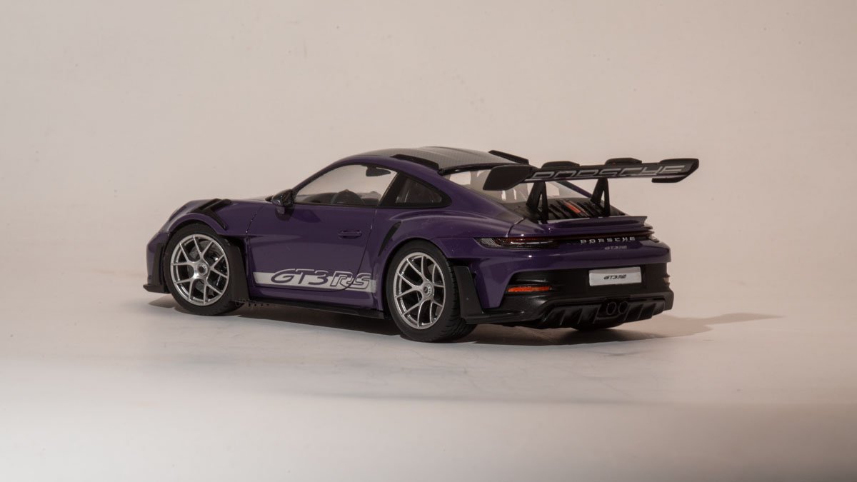
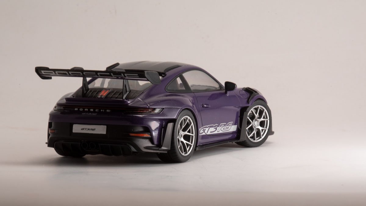
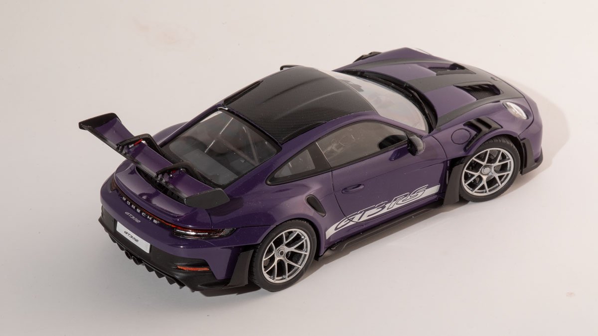
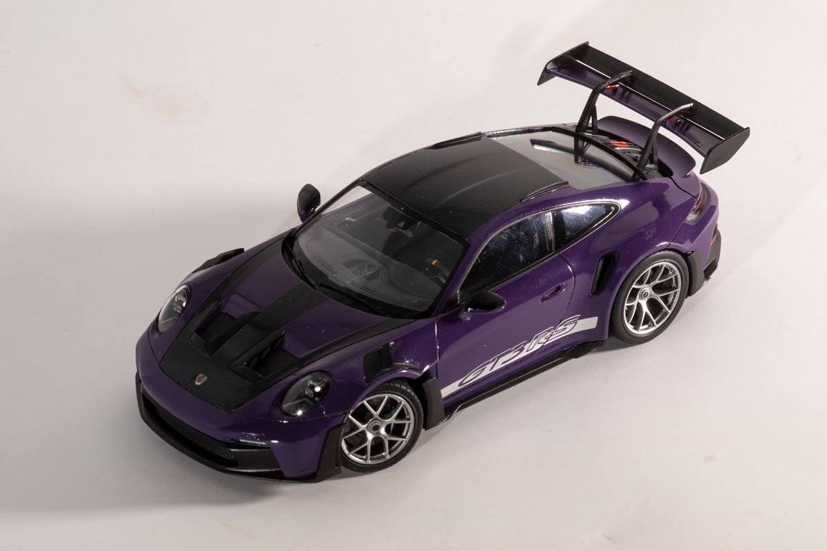
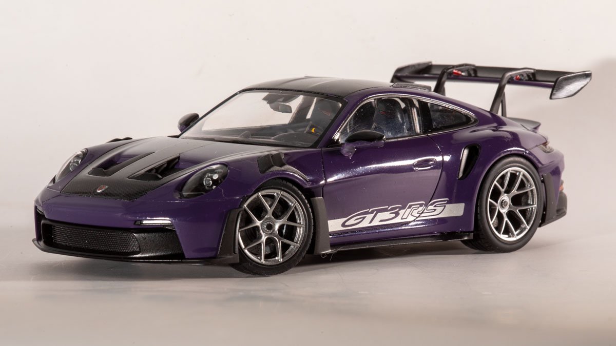
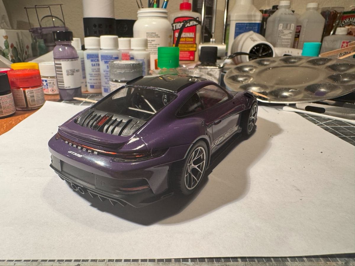
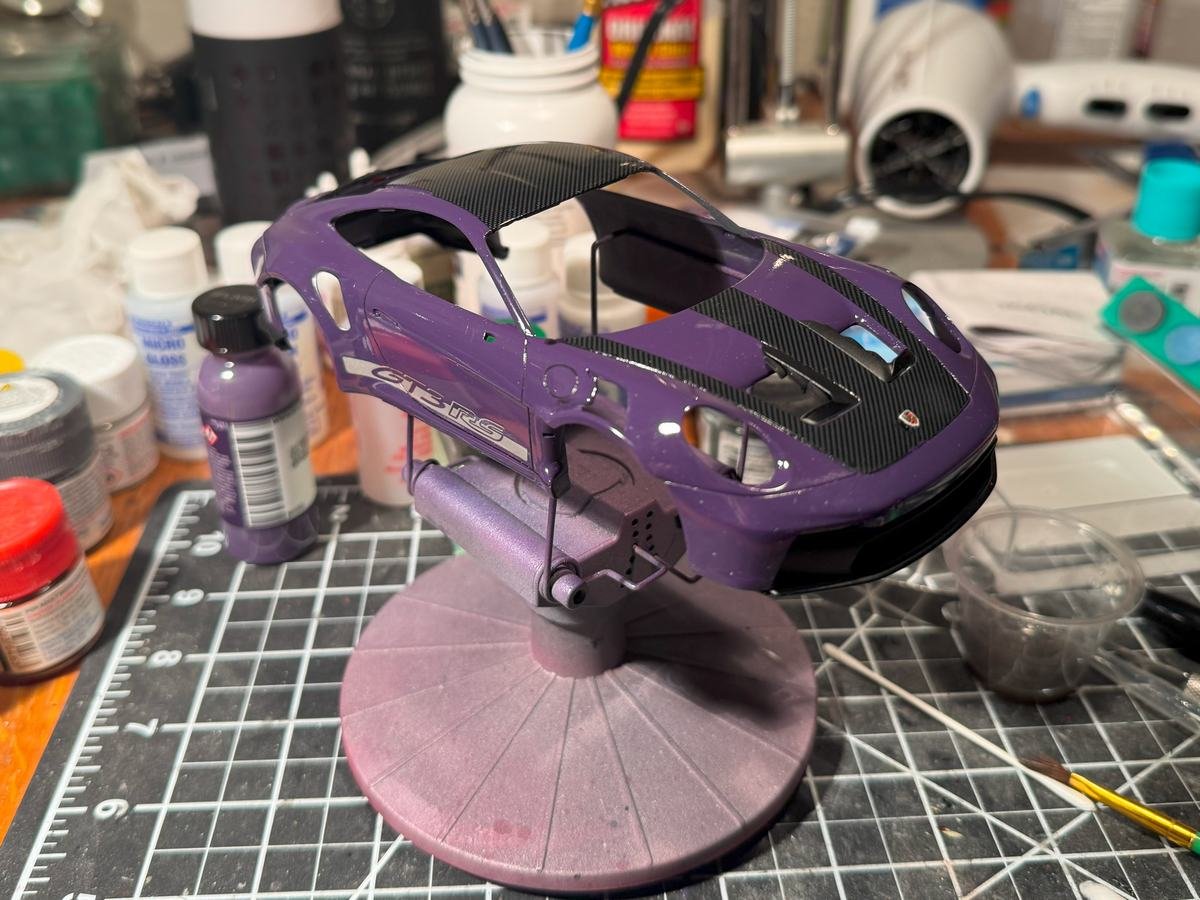
Thanks all for the likes, the comments, and for following along on this quick build. I've now completed the Porsche 911 GT3 RS. Those sharp-eyed among you might notice that there is no carbon fiber on the mirrors. That was a bit of a fail so I just painted the top gloss black and left it at that. Each mirror top half had 3 carbon fiber decals to apply. The first mirror went ok, though the top decal was not very smooth, despite using decal setting solution and a hair dryer to soften it with some heat. I then went on to the second mirror and while using the hair dryer, the blast of air caught the edge of the decal and blew it off the mirror to who-knows-where. I searched around a bit for it but could not find it so at that point gave up on the carbon fiber on the mirrors. Oh well. Otherwise, I am generally pleased with the results. There are still a few minor flaws with the paint work on the body but nothing major. Oh, I also had some problems with the decals on the wheels....there is supposed to be a tiny round decal on the wheel center lock. Two of them came off during assembly so I just painted the top of the center lock black. And now looking at the pictures I see that a third one of those decals went away, so I need to paint that one black too. Oh, did not mean to be that long-winded. Here are the final pictures.
- 13 replies
-
- 12
-

-
-
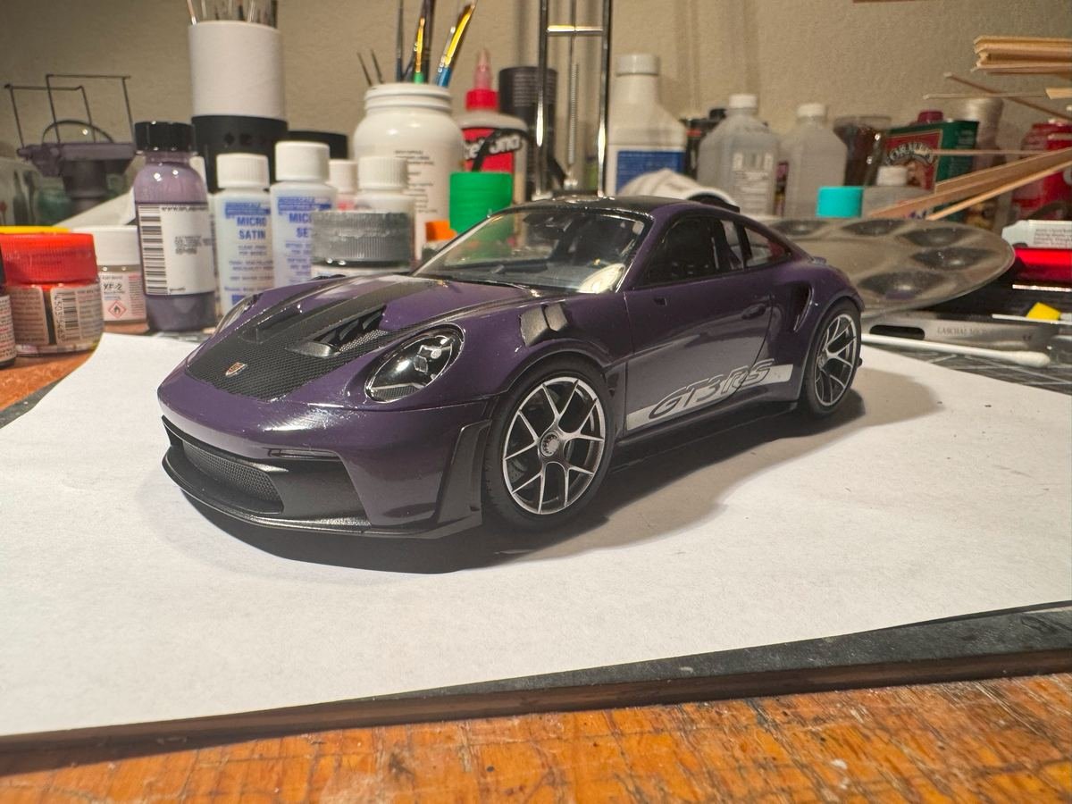
Thanks for the likes or just stopping by to take a look. She's now down on her own wheels and very lose to completion. Just need to do the mirrors, door handles, wing, and some air deflector thingies behind the wheel. Then try to do any clean up and touch up and take some better photos with the real camera and better lighting set up. One might think the rear view mirrors would be simple but no....each one is 4 pieces and 3 carbon fiber decals. The wing is a bit delicate too, though I have it mostly done.
-
Beautiful! I thought the kit wheels in the previous post looked pretty good but the after market ones are a significant improvement. I might need to get a set of those if I ever get around to building my 250 GTO.
-
Been working a bit more on the body bits but have continued to put off painting the windows. I need to tackle that soon.
-
CA (cyanoacrylate) "super glue"
gsdpic replied to Dr PR's topic in Modeling tools and Workshop Equipment
I've used the Loctite gel in the fancy applicator bottle to the end of the bottle. For me, the more likely failure is for the glue to take longer and longer to cure after opening the package, as the glue ages. Is Corvallis, Oregon particularly humid? Superglue cures by chemical reaction using moisture in the air. Maybe a particularly humid environment makes it more likely to harden before being used up. -
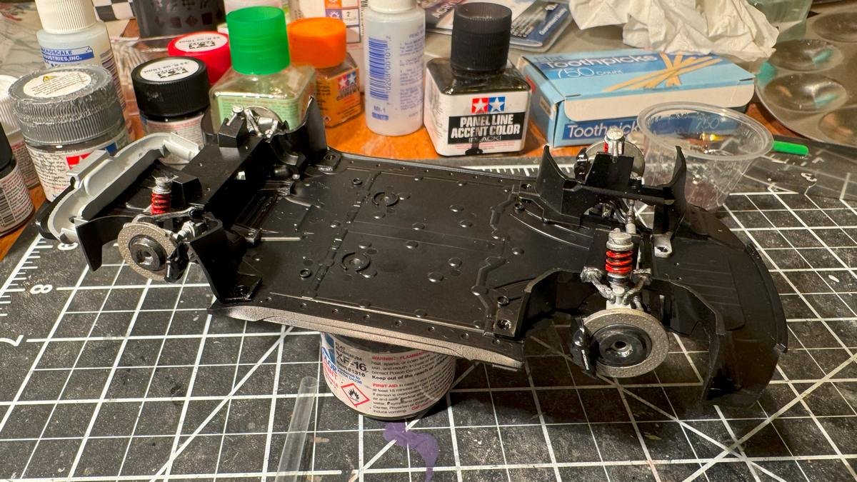
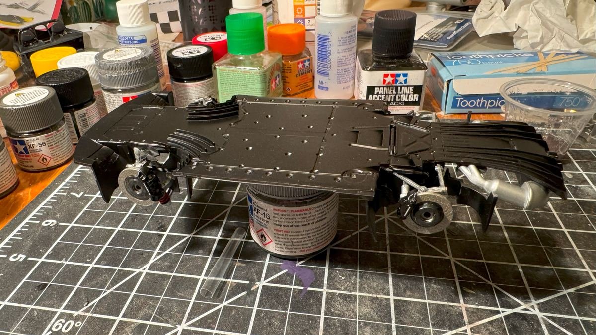
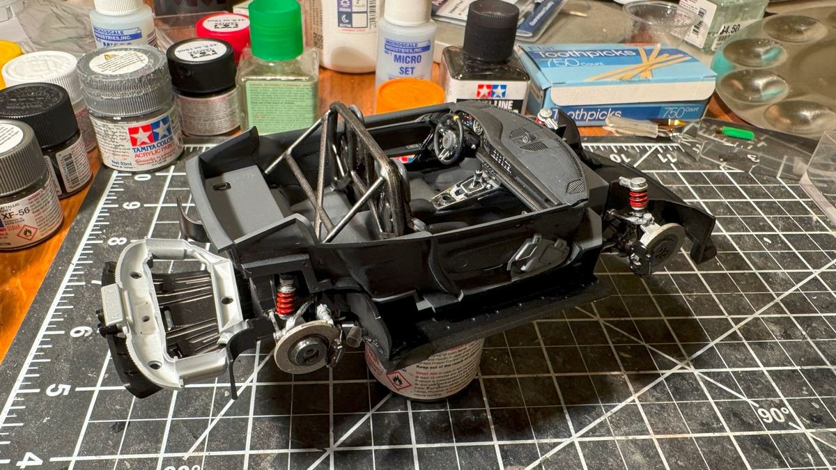
Thanks for the likes or for just looking in. I've now completed the chassis and put the interior on the chassis. From here on it is all about attaching all the bits to the body and then putting the two together. The trickiest remaining thing is probably masking and painting the windows, as both sides and front and back windows all have some black border to be painted. Other than the windows, I think I have all the painting done, except perhaps some minor details here and there. I added a few more coats of clear to the body and it is looking shinier but have not done any sort of polishing just yet.
-
Ok, I sanded down the color coat (just once!) and repainted and it is looking good. Now to mark the waterline, tape it off, and paint the hull with the dark green paint. Haha....I see now some of the test prints from my recently acquired 3d printer in the background. I took this shot by my computer instead of in the modelling room.