drobinson02199
-
Posts
1,075 -
Joined
-
Last visited
Content Type
Profiles
Forums
Gallery
Events
Everything posted by drobinson02199
-
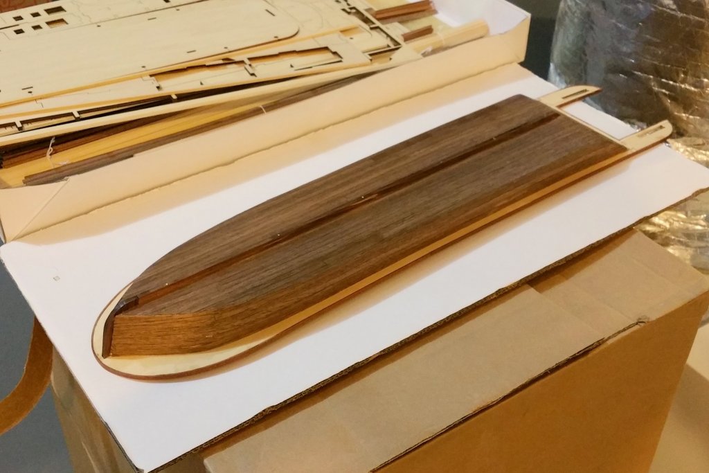
 I have now completed the hull planking. Pictures after the first coat of varnish are below. I think I'm going to like this boat and like building it, but I have to say that I'm not completely happy with how the walnut hull turned out. The wood Artesania Latina provides for this is flimsy, and chips easily. More comments on the kit itself in the next post.
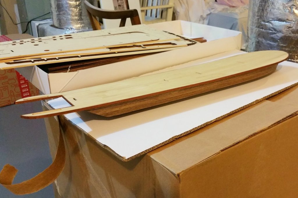
- 104 replies
-
- 5
-

-
- king of the mississippi
- artesania latina
- (and 1 more)
-
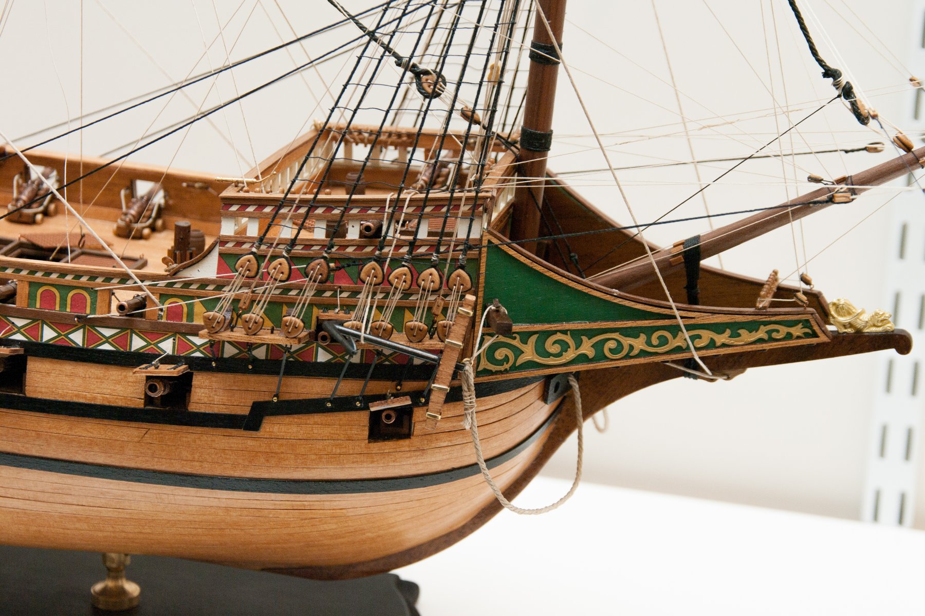
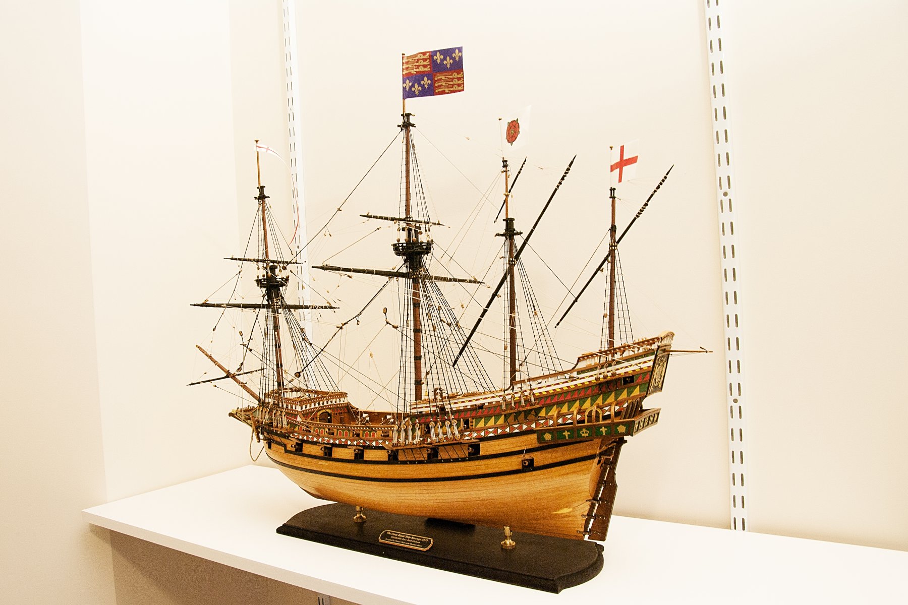
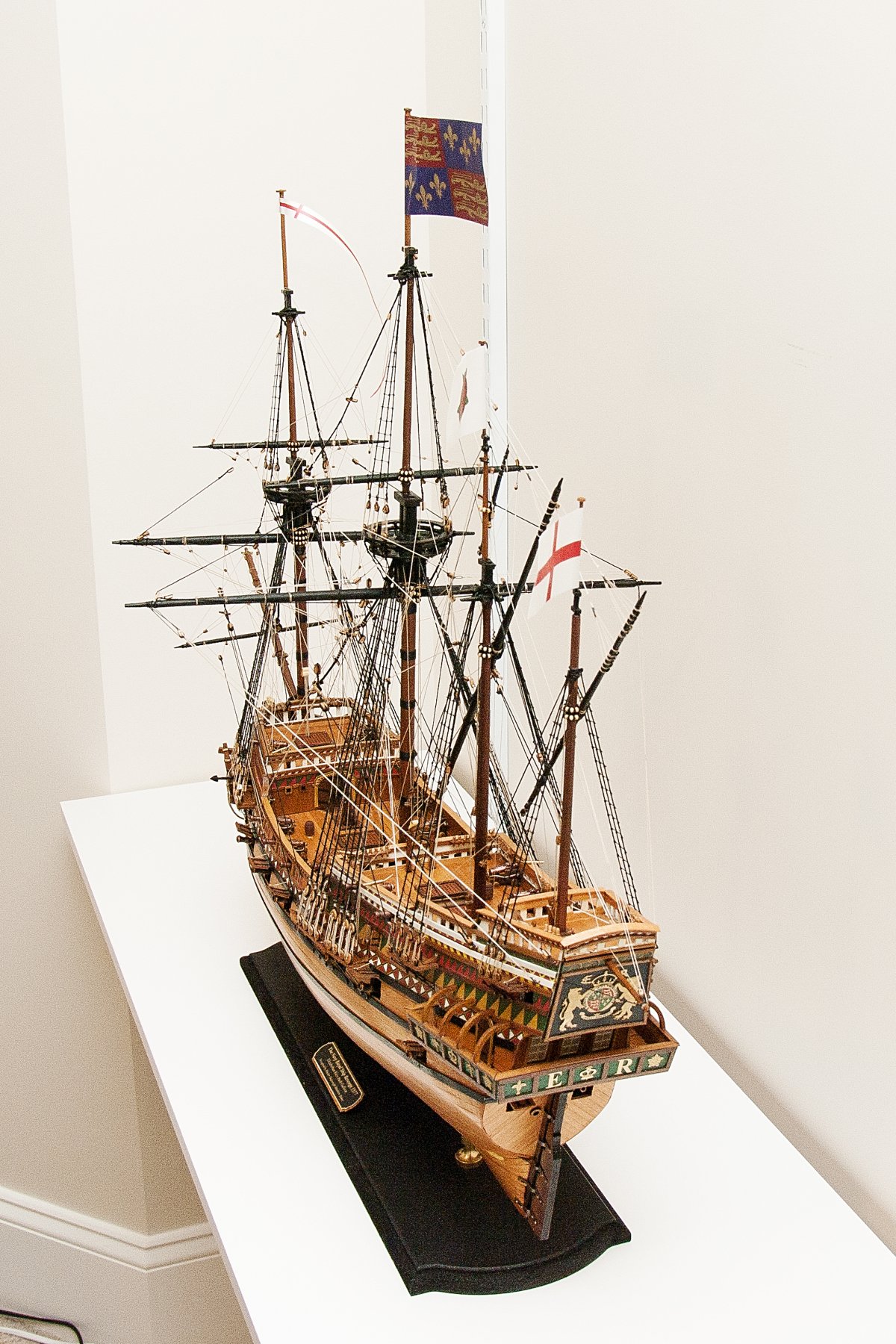
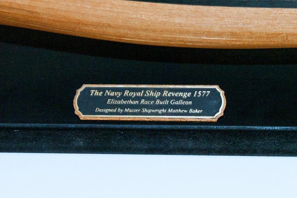
Chris: Thanks for this. I have a real weakness for the look of a natural varnish on the hull. If you look at my Revenge, just completed, you'll see that I didn't paint the bottom half of the hull white (as specified) because I love the natural look. I'm reminded of a post I read a while back that said "It's a model ship, not a piano", but I'm still a sucker for that look. Thanks, David
- 104 replies
-
- 3
-
-
- king of the mississippi
- artesania latina
- (and 1 more)
-
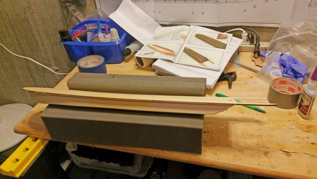
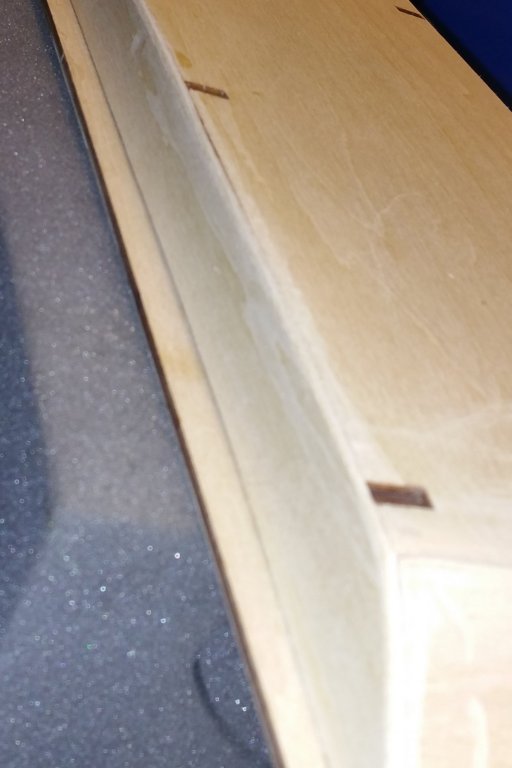
Chris: The deck pattern was like that in the instructions. They called for 10 cm strips staggered. I staggered them, but instead of a 5 cm offset I ended up with 4 and 6, which I continued. I say "ended up" because it started with a measurement error, and so I just continued it. Looks OK to my eye -- but I tend to forgive myself a lot when I mess up. At least one of the upper decks calls for a herringbone pattern. I've started the hull planking, and it's actually kind of tricky. Unlike sailing ship hulls which have a continuous vertical curve, the sides and bottom form a right angle, and the trick is to get that transition without leaving any space or a rough looking corner. I've done one side and the approach I used was to plank the side first with an overhang past the bottom, then lay in bottom strips against the overhang and sand down the overhang. Looks good -- pics will follow when I finish and get the first coat of varnish on. Regards, David
- 104 replies
-
- 1
-
-
- king of the mississippi
- artesania latina
- (and 1 more)
-
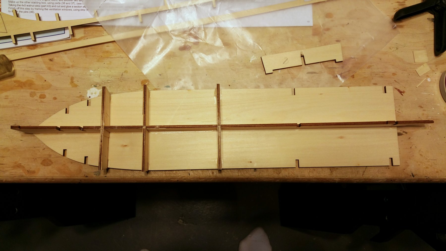
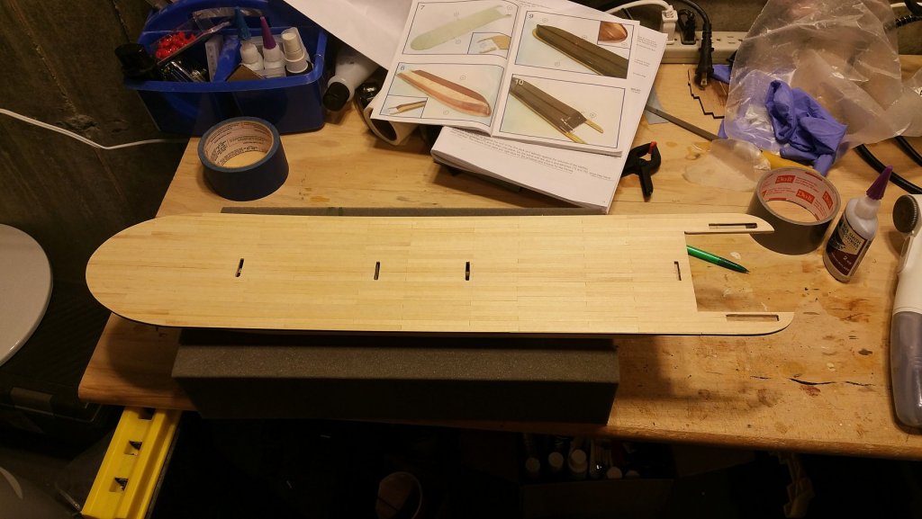
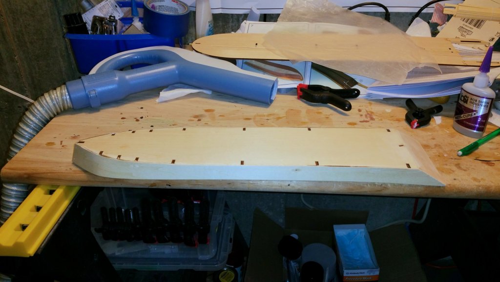
I have finished planking the main deck and have mounted it to the hull. Will wait on penciling in nailheads until I finish hull planking and varnish all of this first assembly. It will be interesting to see how the hull planking works. I have rounded the corners where the bottom meets the side bulkhead, and maybe with some steam I can curl the planks around that to create a smooth transition. That's what the pictures in the manual look like (sort of -- it's hard to tell). Regards, David
- 104 replies
-
- 4
-
-
- king of the mississippi
- artesania latina
- (and 1 more)
-
Chris: The main deck, which is the largest outside dimension of the boat, is 25" long by 5" wide. The hull is a bit shorter and narrower. There is, however, a boom that hangs off the bow, and I don't have a fix on how much total length that would add. The box says almost 26" wide by a bit over 5" wide by almost 12" high. Regards, David
- 104 replies
-
- 1
-
-
- king of the mississippi
- artesania latina
- (and 1 more)
-
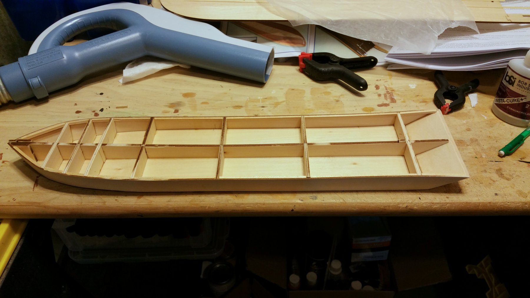
Here's the finished hull with side bulkheads. I fitted the deck (not shown) before attaching the bulkheads, as it's easier at that point to sand down the frames and make sure the tabs fit properly, and the deck seats properly. It also helps with positioning the slanted piece in the stern. Regards, David

- 104 replies
-
- 4
-
-
- king of the mississippi
- artesania latina
- (and 1 more)
-
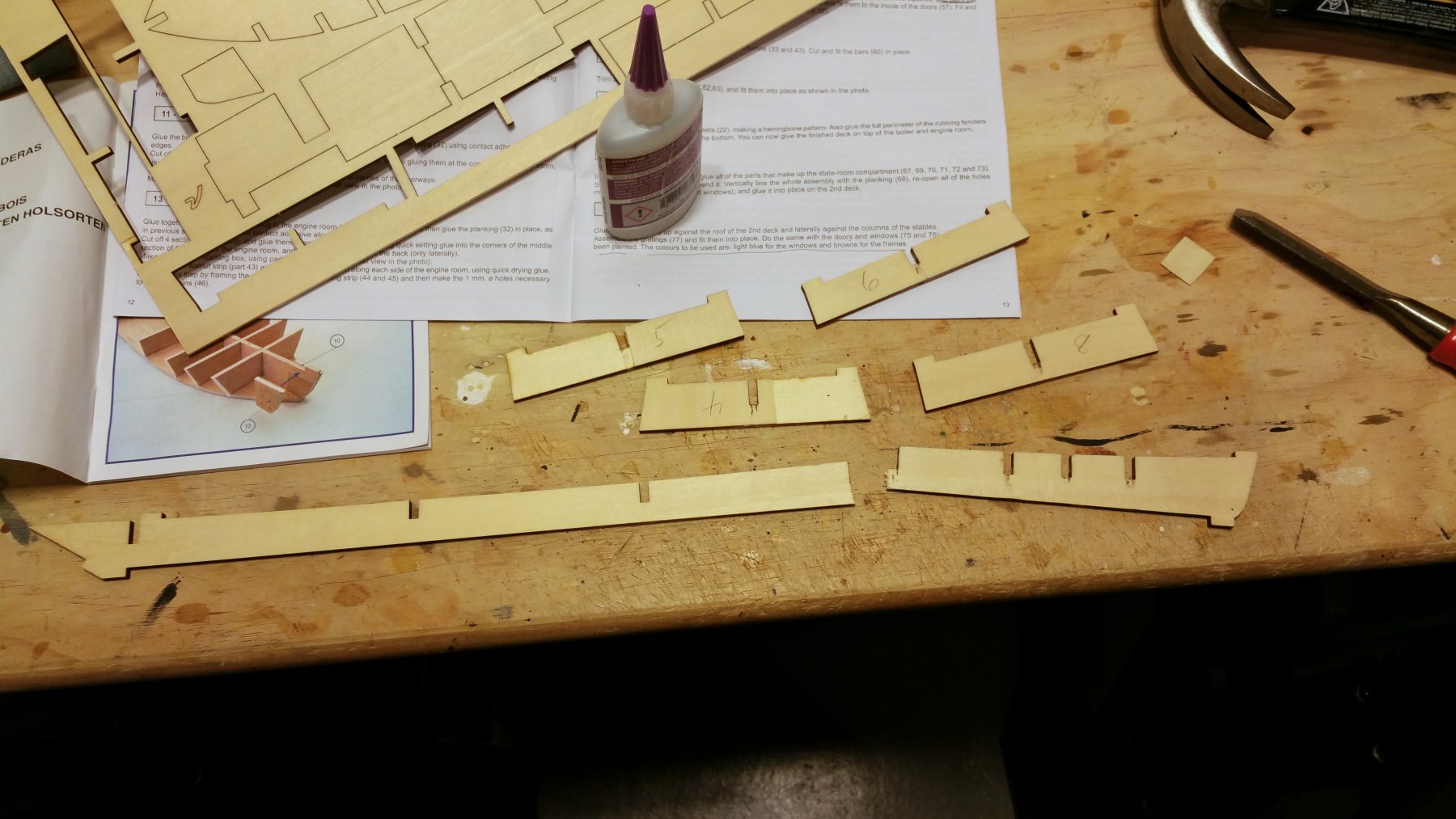
Also, the labeling of frames 4 and 5 is reversed on the laser cut key sheet. This becomes obvious if you are assembling the bottom board at the same time as the false keel and frames. Regards, David
- 104 replies
-
- 2
-
-
- king of the mississippi
- artesania latina
- (and 1 more)
-
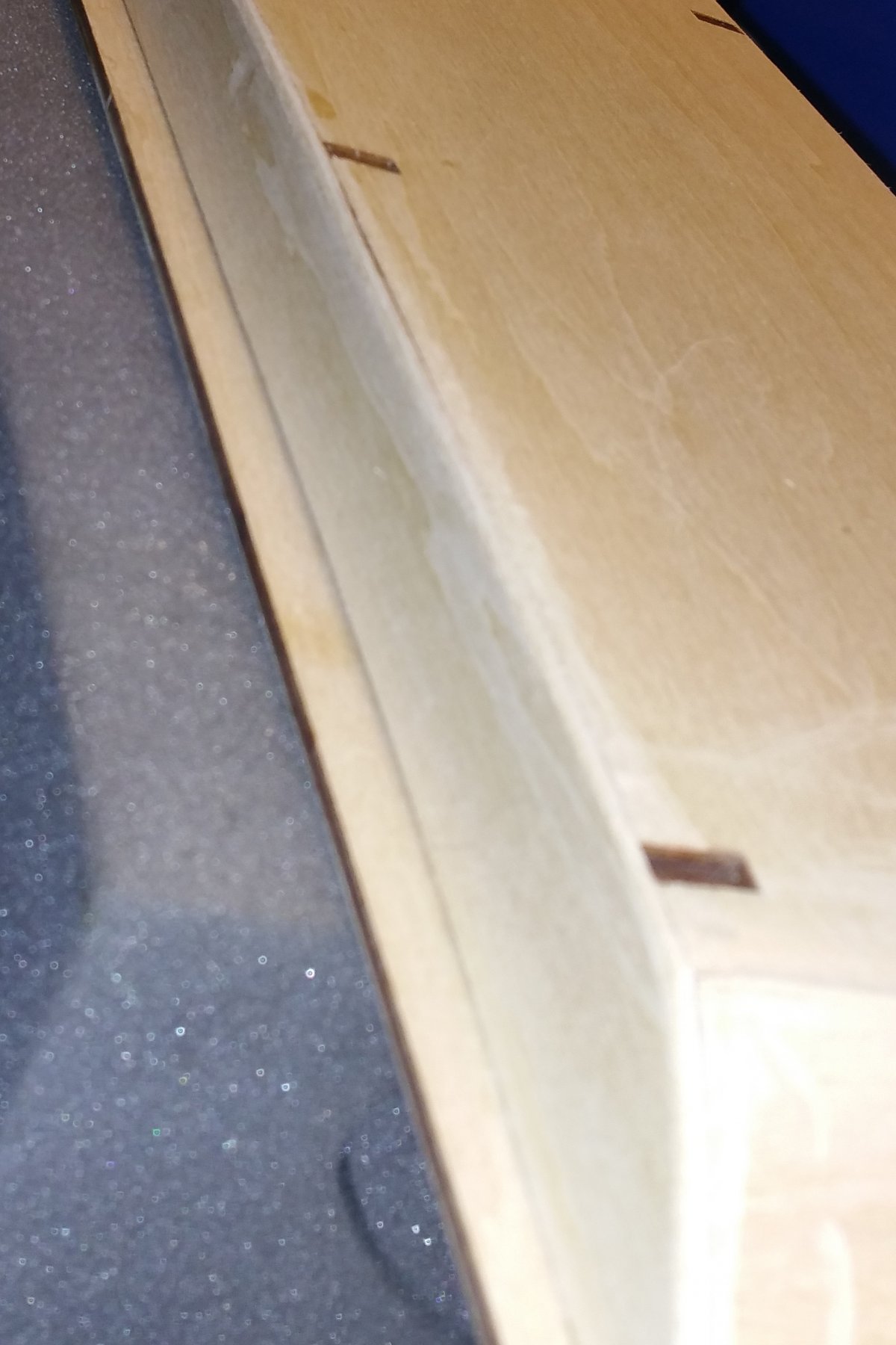
Well, day 1 of the build and I've already made my first doofus move. I wasn't being careful and had the plywood sheet flipped over relative to the key sheet, and took the wrong frames out and glued them to the fore part of the false keel -- using CA glue. Fortunately, discovered the mistake about 30 minutes in and was just barely able to knock the frames off -- but not before the last "knock" broke the false keel into two pieces as shown in the first pic. The fix was to assemble the two halves of the false keel, the frames, and the bottom board simultaneously -- so that the bottom board aligned the two halves and also created structural strength. All fine again. On reflection, assembling frames, false keel and bottom board at the same time is the way to go, so that the frames can be properly aligned (and necessary tab sanding done as you go), but with other ships I've built it was false keel and frames first, so that was the reflex. Need to slow down and look ahead. Regards, David


- 104 replies
-
- 6
-
-
- king of the mississippi
- artesania latina
- (and 1 more)
-
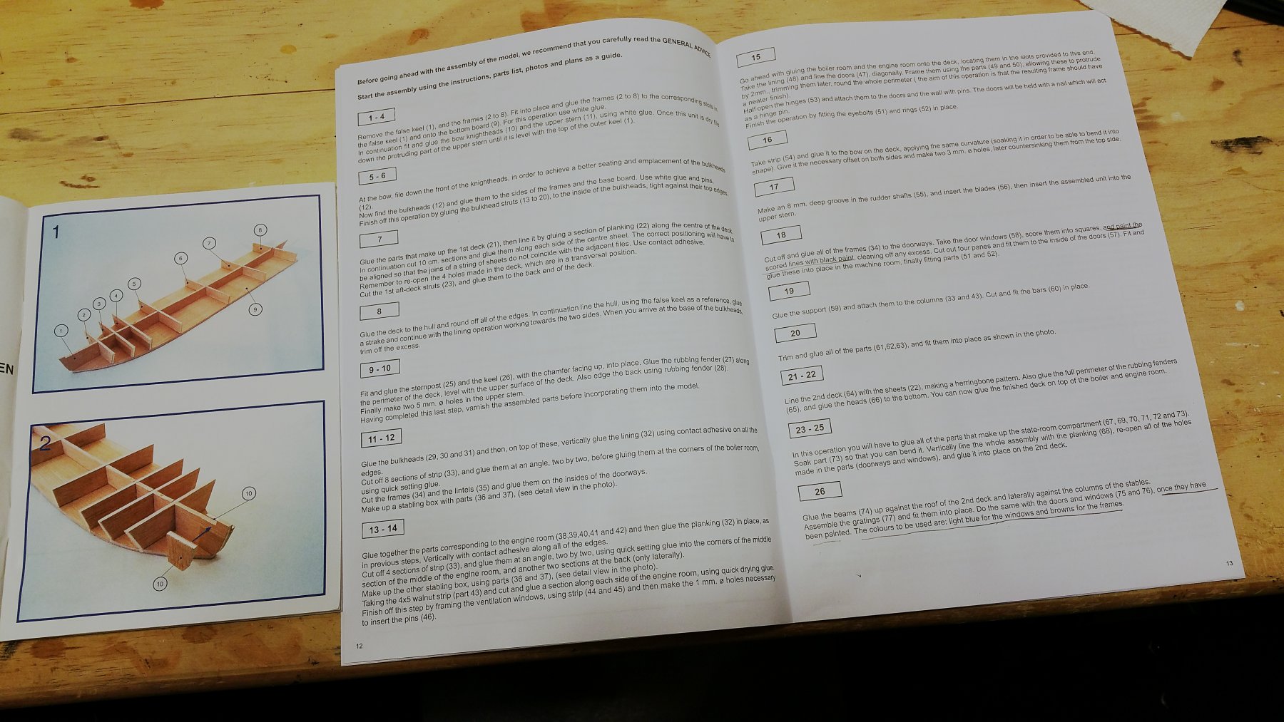
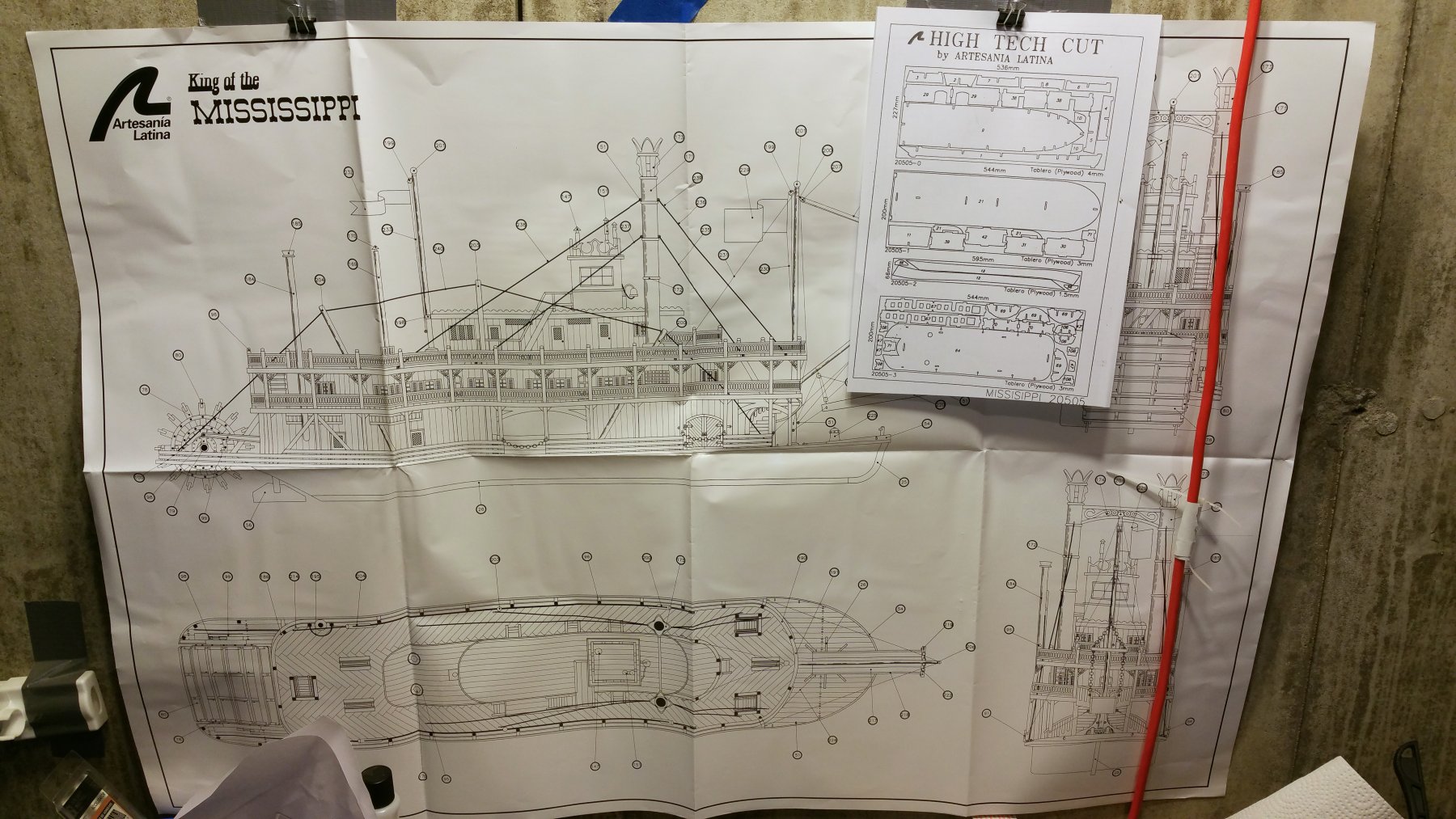
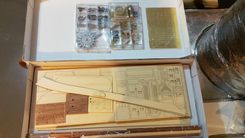
Here's what comes in the box (see pics): Printed instructions with color photos One large plans sheet plus key to laser cut sheets Parts as shown I'll post progress as I go. Regards, David


- 104 replies
-
- 5
-
-
- king of the mississippi
- artesania latina
- (and 1 more)
-
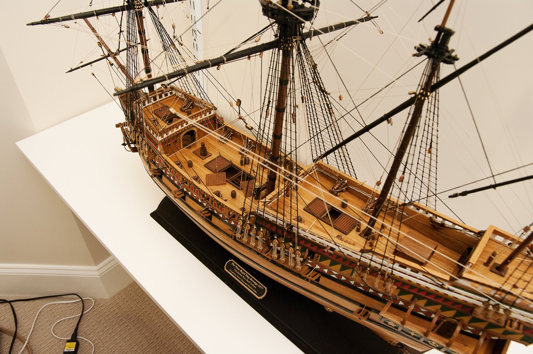
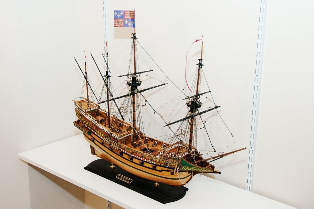
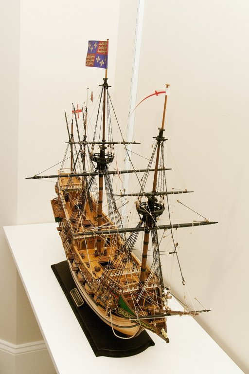
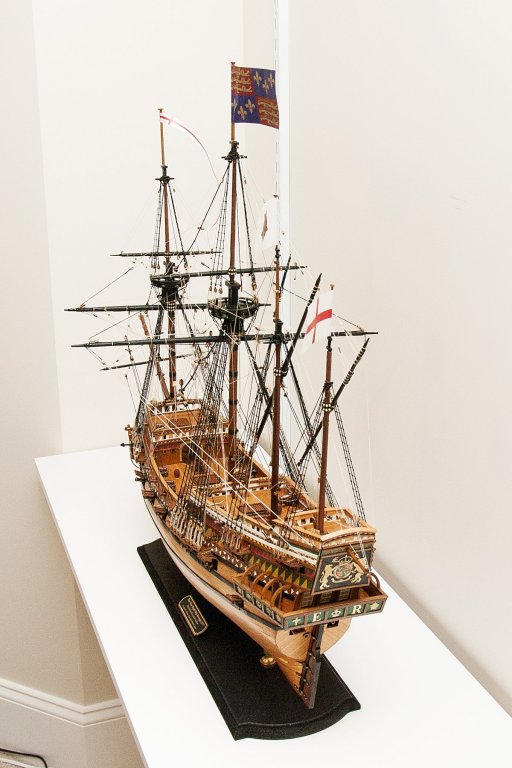
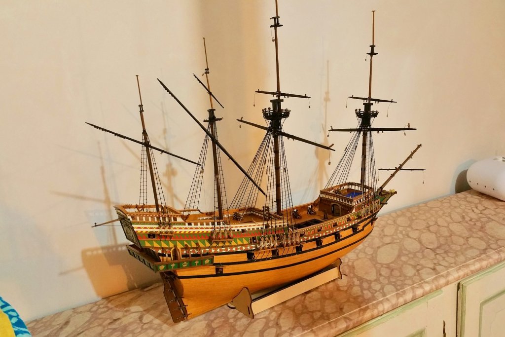
The Revenge is complete! Pictures below. For anyone thinking about this kit, a strong endorsement from me. Really terrific materials and instructions -- and really interesting to build. Now a bit of a breather and then the King of the Mississippi by Artesania Latina. Regards, David


- 60 replies
-
- 26
-
-
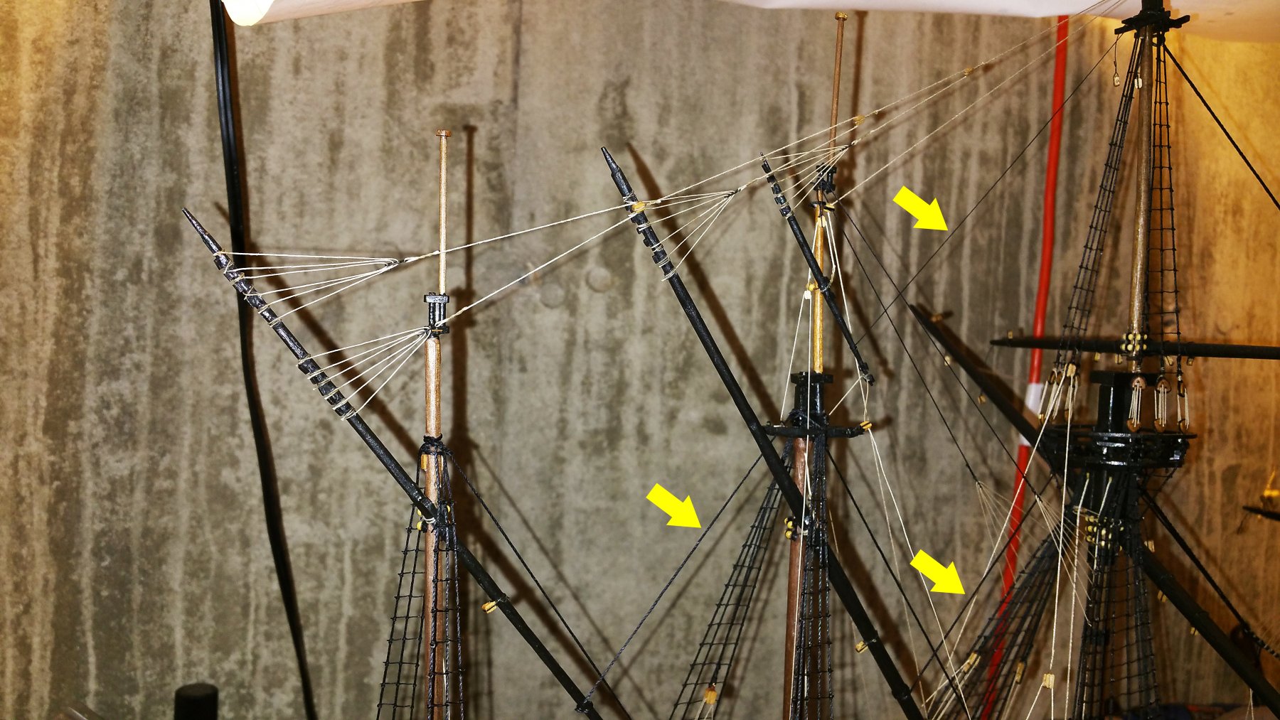
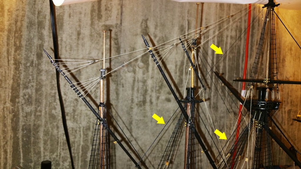
The lateen yard lifts are the "fan shaped" type (does anyone know if there is a nautical term for this? I couldn't find one). That fan shaped rigging requires tension to look nice, and in the rigging diagrams there were a lot of rigging elements pulling the yards in the same direction as the lifts do, but nothing I could find (including on the 3D pictures) that provided an offsetting tension. In the absence of that offset, the fans would all sag and it would be very difficult to keep the lateen yards parallel. So I have added the three stays you see in the picture marked with yellow arrows, and that worked well and I could tension and adjust the fans. The other modification I made was to use 6-spoke fans vs. the 5-spoke ones called for on the plans. From the prior fan rigging, which also called for 5, what I found is that the glue needed to hold a single thread in the lowest spreader hole stiffens that thread just enough to make it really hard to get the fan spokes to tension evenly and look nice. So I just went to 6-spoke fans, which keeps glue off the spreader and off the spokes, and provides a better look to the fans. Regards, David
-
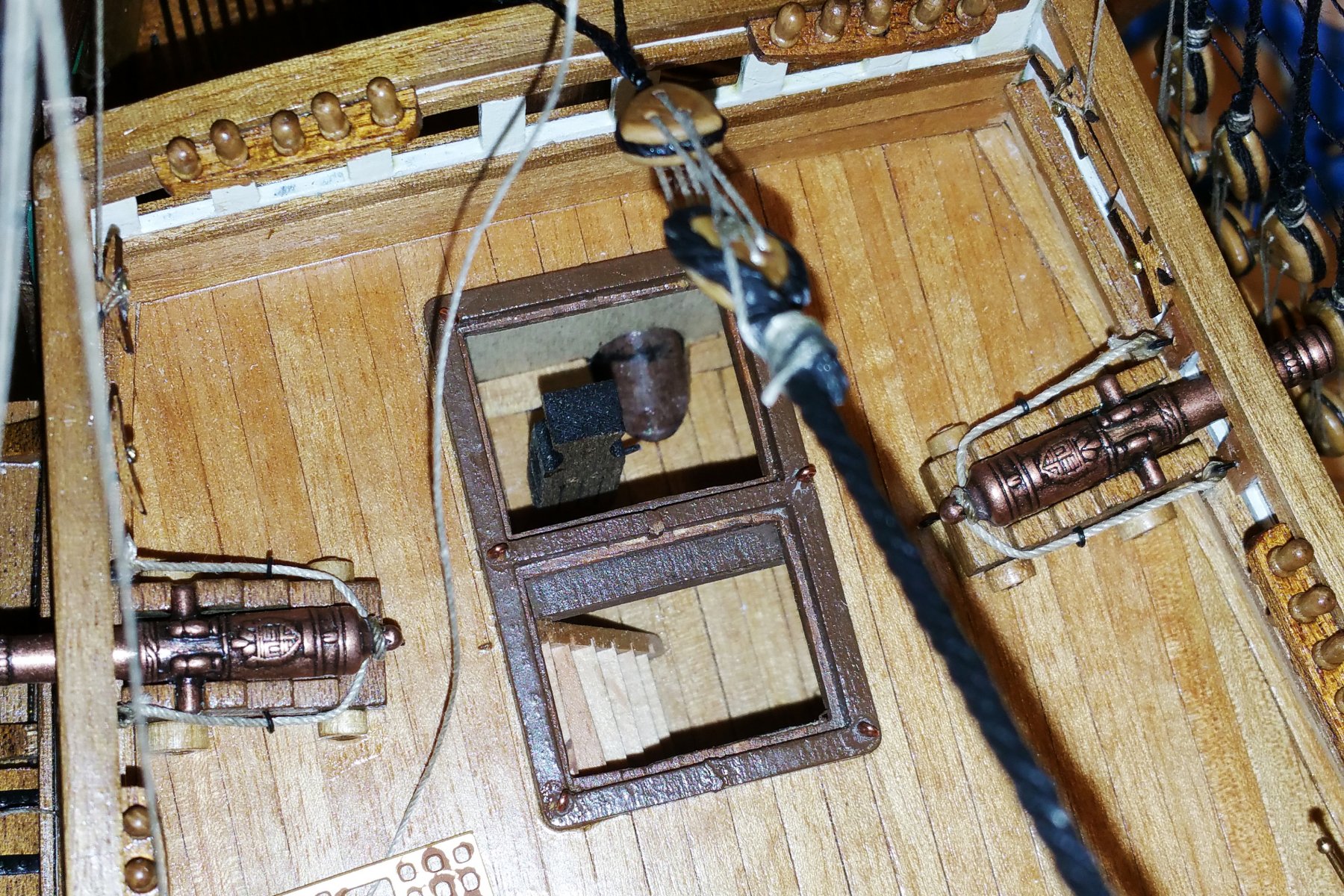
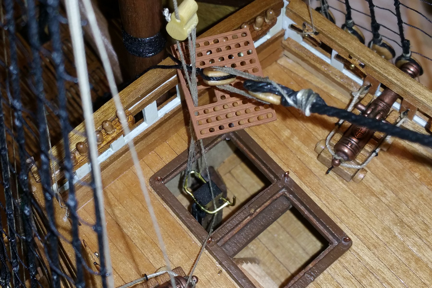
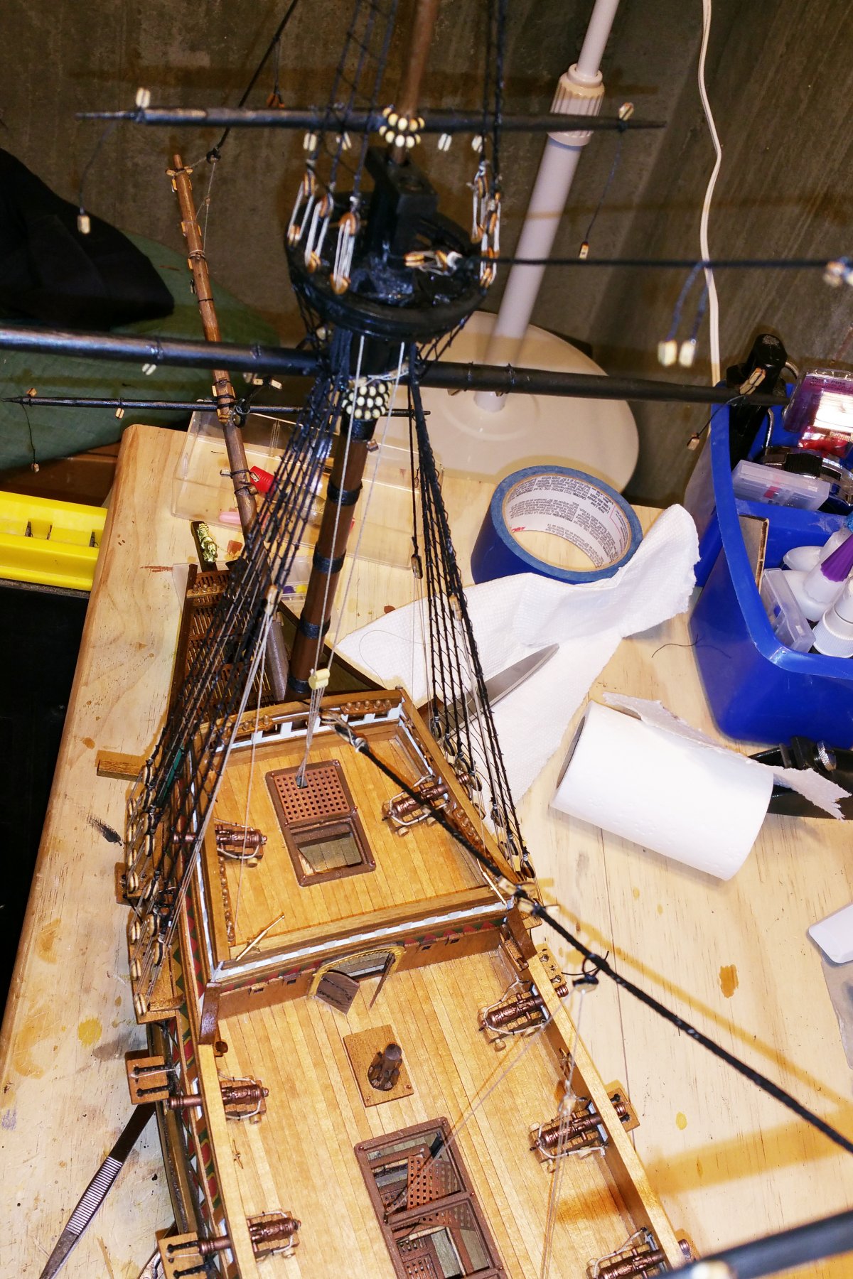
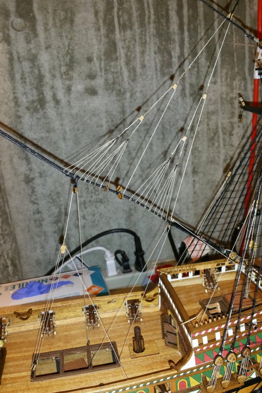
Another interesting and good-looking piece of the rigging. This is the foremast upper yard lift. All of the elements you see are free to slide back & forth in the blocks, so getting it all even was something of an engineering challenge that required some planning regarding how to rig it up. It's more difficult because the only point of downward tension on the large black horizontal stay was the tackle you see over the center of the three hatches. That didn't provide enough tension on the right side of the rigging. So I noticed that I had installed a block (per the original plans for that stay) that didn't seem to be on the yard lift diagrams, and it's also missing in the 3D pictures, so I "hijacked" it and installed the rigging on the right that runs down to the right hand hatch and provides downward tension to the right side of the rigging. This gave me the support needed to put enough tension on the rigging that the "fans" look decent. If it turns out I need that block, I can always cut that added tension line (it's attached to the hatch by hooks). I tried to keep the upward bow out of the large black stay, but it's not really possiible to do that and get enough tension on the rigging -- and I noticed that there is some of it on the 3D pictures, so I guess it's OK.
-
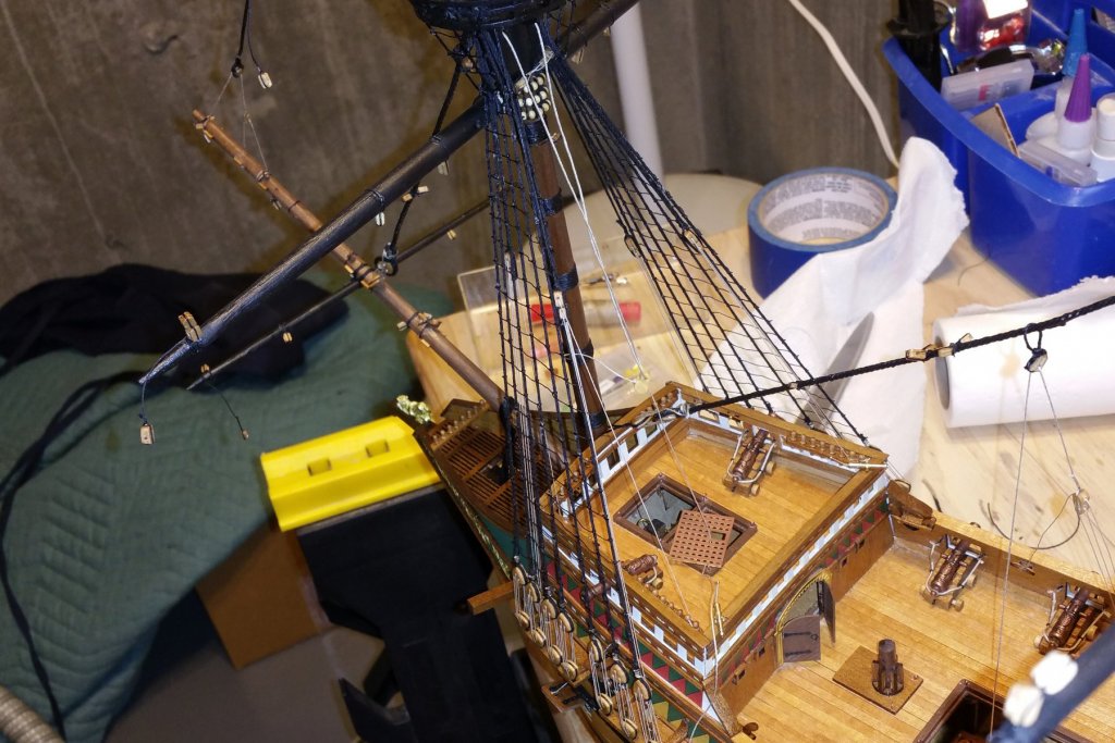
Re my previous post: here's the rigging for the main mast lower yard. The kinghthead is on the main deck, and I was able to thread the rigging and adjust and tighten it. The picture here shows what this rigging is supposed to look like (that I didn't quite get on my foremast rig). Regards, David

-
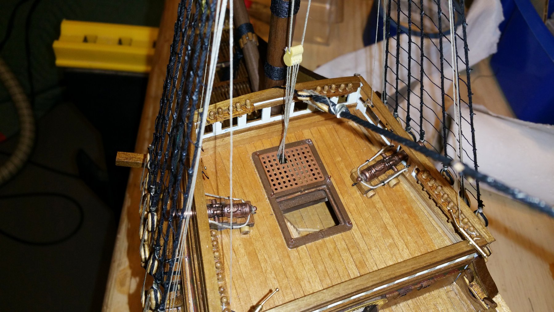
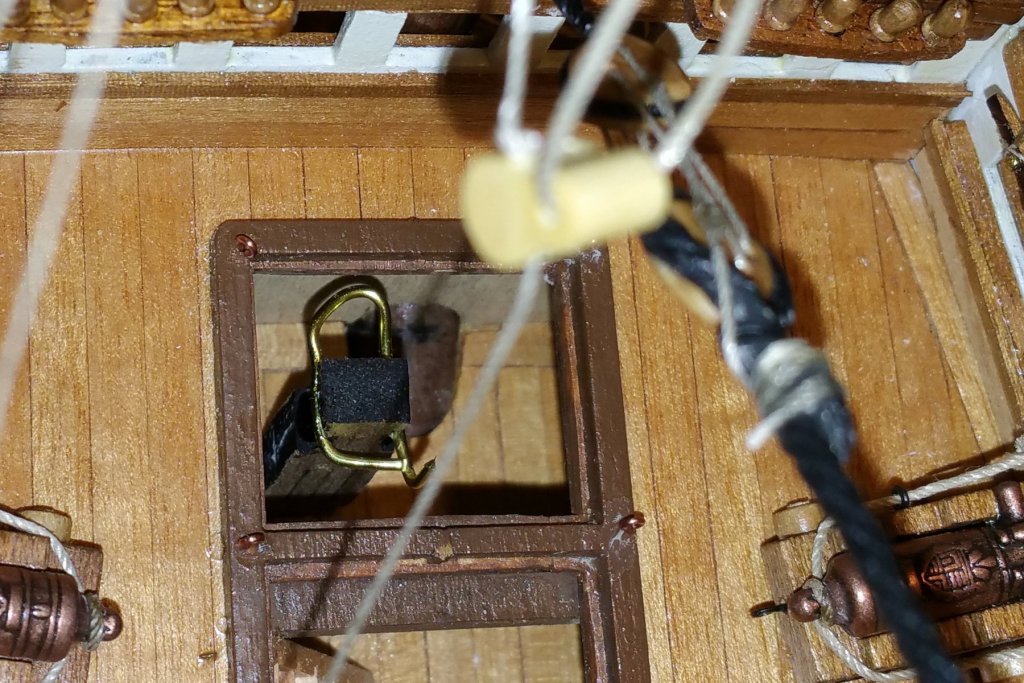
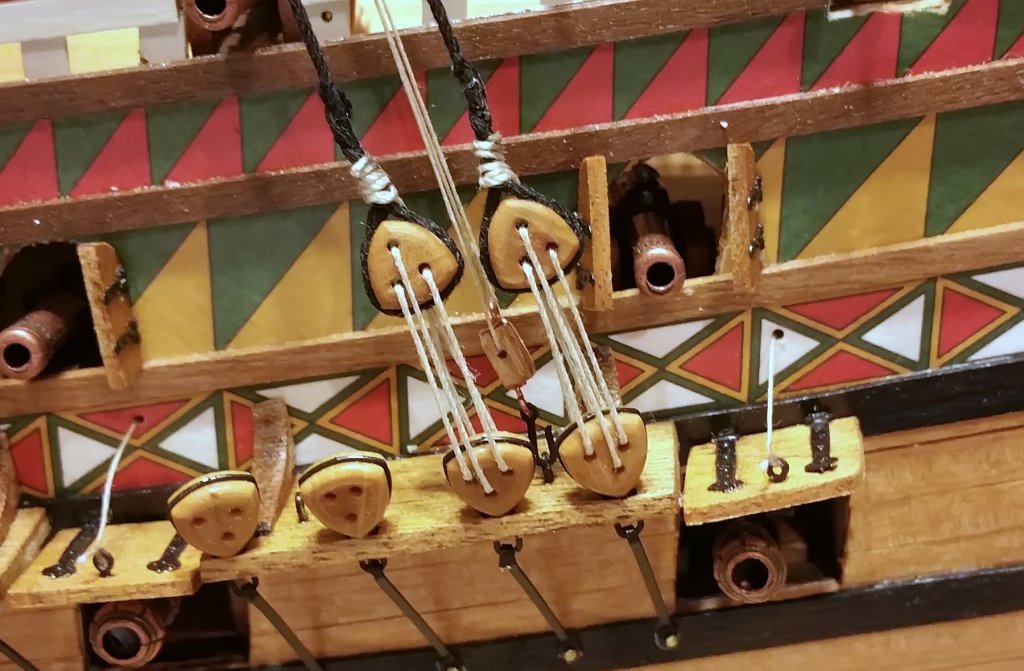
My wife is fond of the nautical term "jury rig" when referring to my "around the house" handyman skills, as in "Oh God, you're not going to do another one of your jury rigged things!" So I had to apply that instinct today on the Revenge. If you look at the first two pictures, the foremast yard lift rigs down to a knighthead that is installed on a lower deck, and you have to rig it through the hatch. The instructions at a much earlier step (like two months ago) say to drill holes in the knighthead before installing, and I did, but they weren't large enough. After many tries, I was stuck, as I had no way to enlarge them down through the hatch, and I couldn't get the line through, even with CA stiffener. While the wonderful 3D pic of the Revenge shows that hatch cover ajar and off to the side, it has a square hole in it for this rigging, and I had decided to rig through the hatch and close it, just for fun, which meant that the knighthead wouldn't be visible. So I jury rigged the brass wire fitting you see in the third picture, and attached the threads to the wire loop as in the fourth picture. The last two pics show the hatch closed. The big downside of this is that the lines don't run parallel as they would if I had used the knighthead, and so it doesn't look as elegant, but I got the rigging done and the main mast lift and others will look better, as all of the knightheads are on deck and easier to access. For any of you who are at an earlier stage of the Revenge, the booklet instructions for that knighthead are on page 46, and the instructions call for 1 mm holes. I would go larger -- as large as you can get away with while doing 3-across. Live and learn. Regards, David


-
Antony -- You are very kind. Thanks. I'm mostly trying to keep from going blind peering through the shrouds and ratlines now. :-) Best regards, David
-
I think this "fan shaped" rigging from the mizzen to the main shroud has a nice look to it. Took some care to keep everything lined up on both sides of the main mast.

- 60 replies
-
- 10
-
-
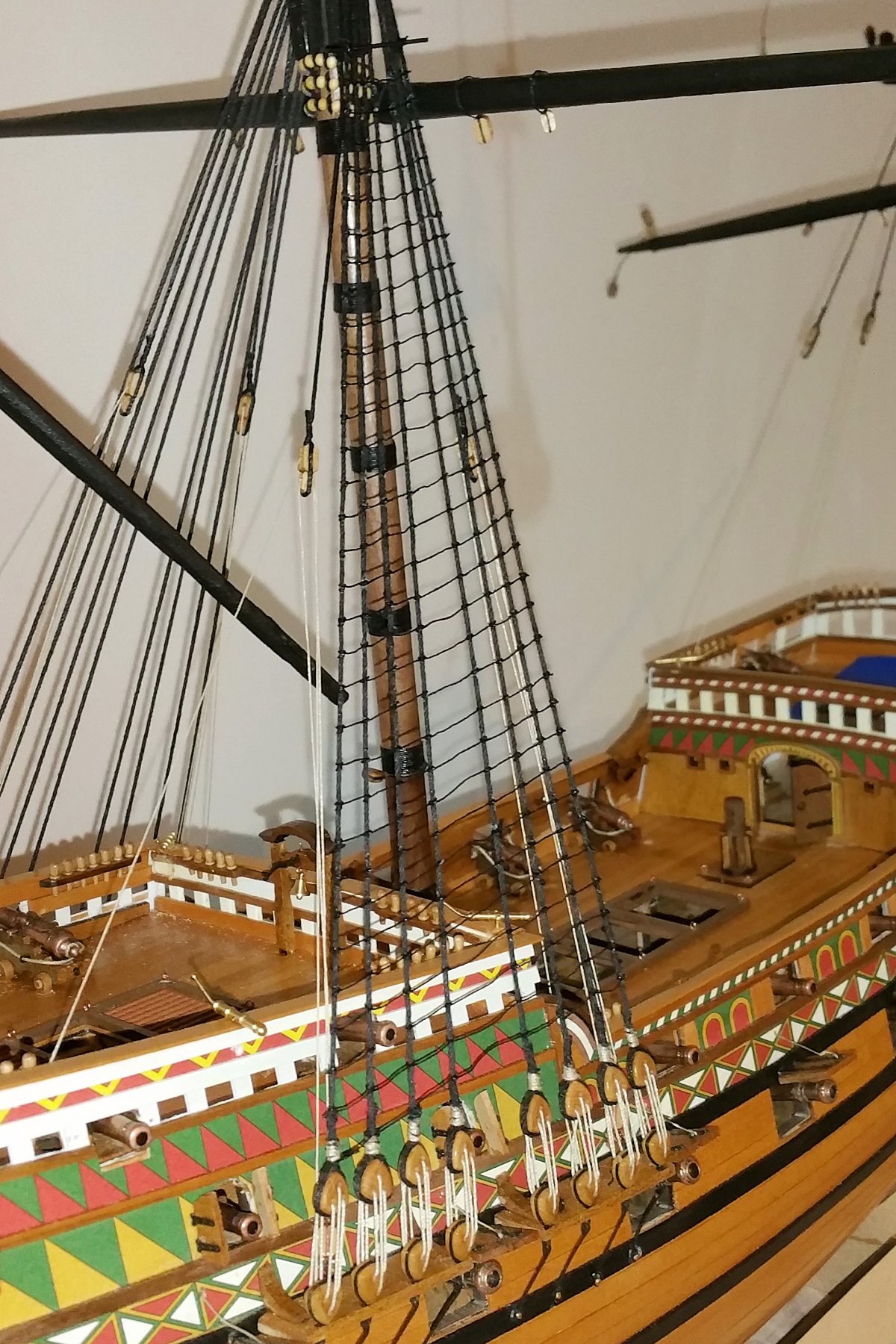
The lower shrouds are finally done (see picture). I think at this point I could tie ratlines in my sleep with both hands tied behind my back. Leaving tomorrow for a 2 week cruise with my wife -- then back to tackle the upper shrouds and the rigging beyond that. Best regards, David
-
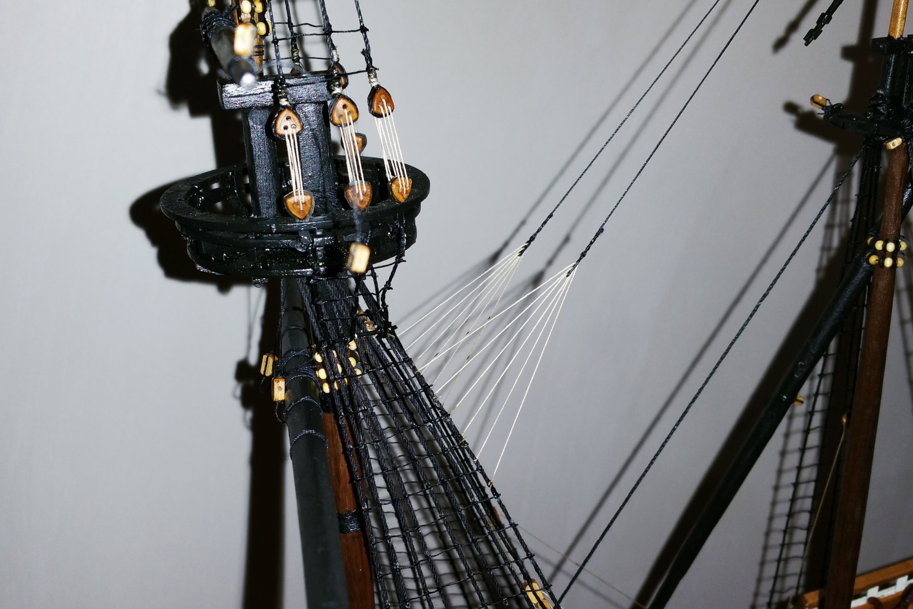
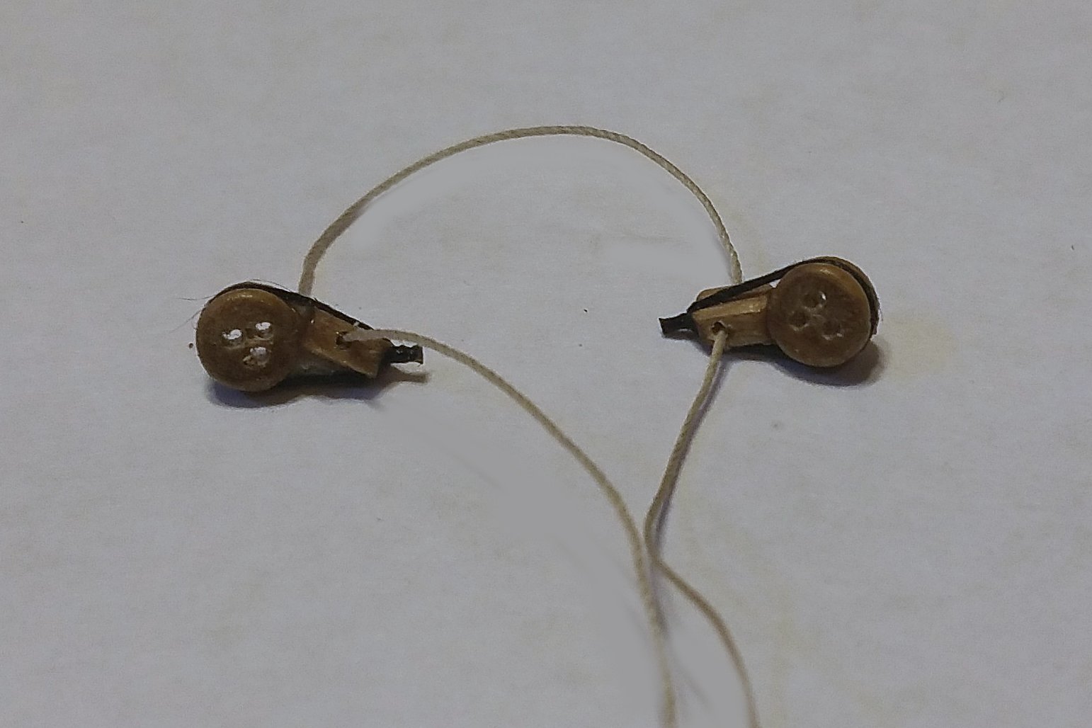
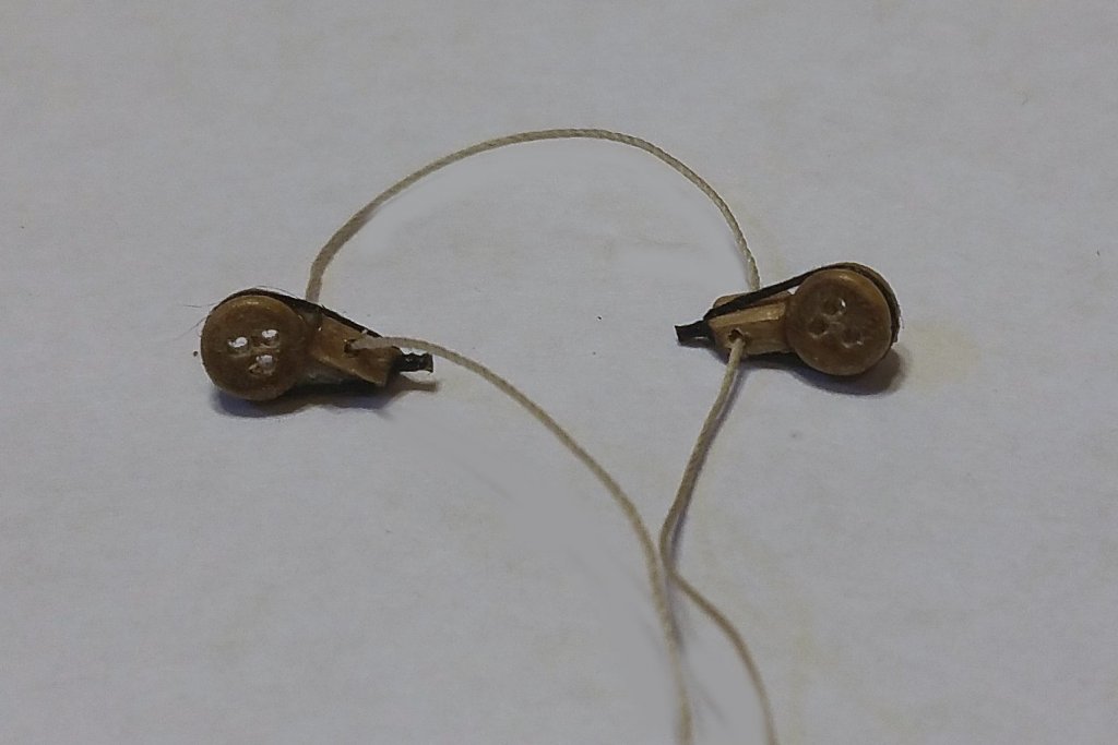
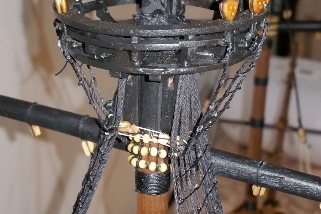
I finished the lower shrouds on the main mast, including the futtock shrouds. It took me a while to figure out the drawing on the rigging for that. The first picture is the block and deadeye assembly that goes between the shrouds at the top. The deadeyes are rigged to a piece of wire at the top of the shroud that runs parallel to the ratlines. Then the assembly is snugged up with the line you see here to create some tension on the shrouds and give support to the futtock shrouds. The second picture shows the assembly in place with the futtock shrouds done. I can't tell from the 3D picture of the Revenge if there is much tension drawing the shrouds in as I have done, but I thought it looked good, so I put the tension on them you see here. The futtock shrouds are also rigged to that piece of wire on each side. Now on to another mast and more shrouds and ratlines.
-
I haven't had as much progress because I was away on vacation last week, but with that said, I'm into shrouds and ratlines, and ratline rigging is SLOW! Here's a picture of the ratlines on one side of the main mast, which is all I've been able to finish since I last posted almost two weeks ago. I have installed the 1mm wire at the top for the futtock shrouds. I found the drawings for that difficult to understand at first, but I think I have them now (with the help of the really terrific 3D rotating picture Amati supplies online). When I bought this model, I also bought the Amati Loom-a-Line, thinking that it would make the shrouds and ratlines easier and neater, but it's clear that these shrouds need to have the ratlines rigged on the boat given the deadeye setup, and I imagine that's true for most high end models. So a question for any of you who have been down this road a few times: when can the Loom-a-Line be used? Scratch builds only? Never for a kit model?
-
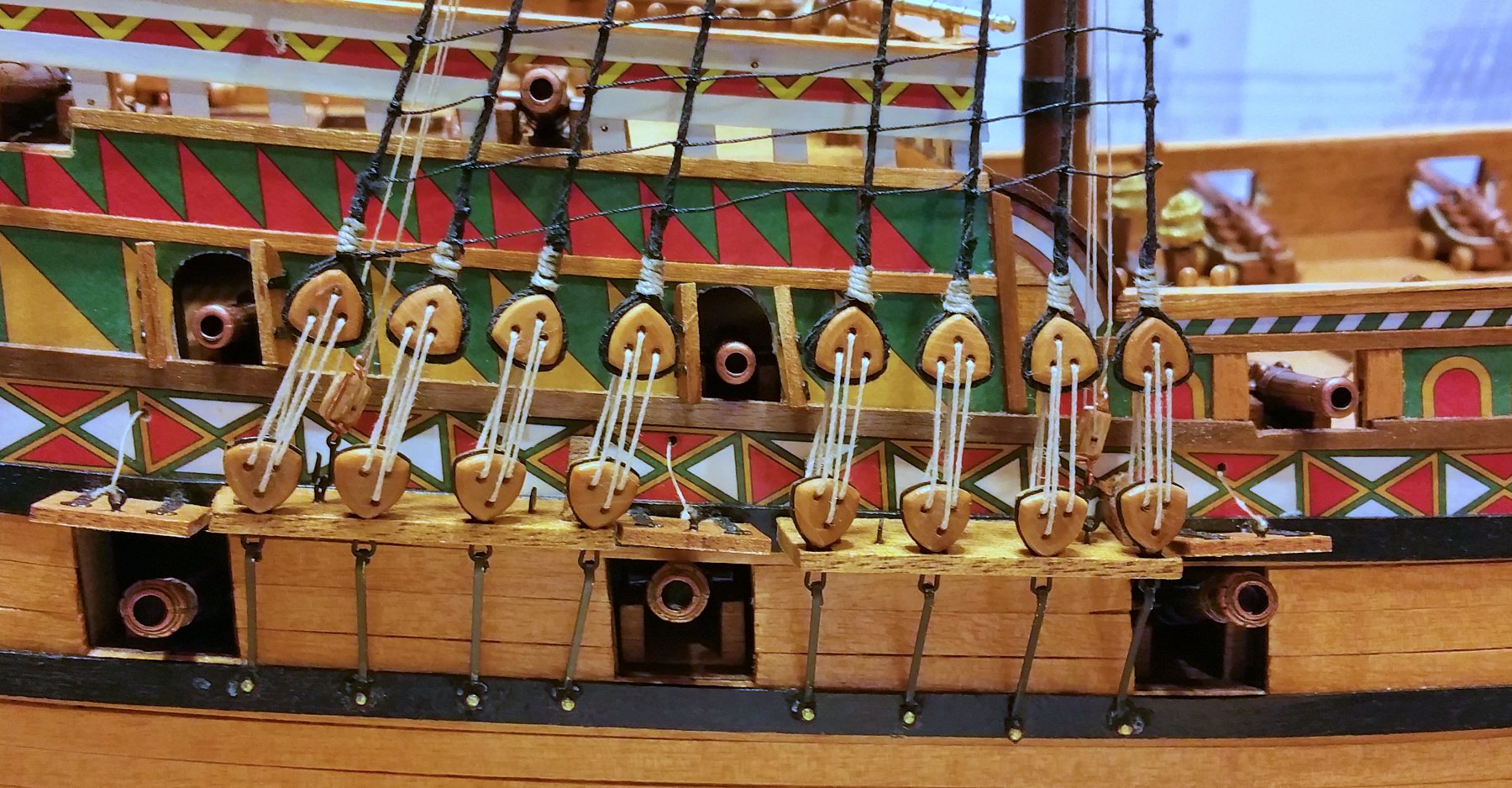
For those of you who have been following this, I completed the main mast shrouds using the "one shroud at a time" approach I mentioned above, and in terms of getting the deadeyes nicely aligned, it worked well and was much easier to manage. See picture below. Steps: Attach deadeye to loose shroud Loosely rig deadeye to the one on the channel, and leave it maybe 3mm above where I want it. Wrap the shroud around the mast at the crow's nest, create moderate tension, and weight with rigging pliers to hold in place. Snug down the deadeye rigging until it's aligned. This puts additional tension on the shroud. I found that this approach allowed me to adjust up and down until I got the alignment where I wanted it. Glue the shroud at the crow's nest Check final deadeye alignment, dress the rigging around the shroud and glue. This goes fairly quickly. On the plans, Chris Watton ties the two strands on each shroud loop together up at the mast, so that the shrouds won't cross. I found that I had to wrap them around the mast in the same direction in order to avoid crossing. As the picture shows, I'm now doing the ratlines on these shrouds before moving to the other masts. I want to see how this "one at a time" approach works when I get up close to the crow's nest and when I have to rig the futtock shrouds. More on that when I get there, which may be when I get back from a week away. Best regards, David

-
Having completed the mast rigging, I started on the shrouds today, and following the plans, used the approach of looping a shroud around the mast and attaching two deadeyes. The issue that arises is getting the upper deadeyes on the shrouds precisely aligned, so that they look really nice. I rigged the first deadeye, but found that if I left the loop around the mast loose, it was impossible to get the right length on the second one and maintain a good tension. So I tensioned the first one, and then fixed it to the mast with glue. That left the second one firmly fastened to the mast, and then I could line up the second deadeye and attach it to the shroud. Final alignment achieved by twisting the shroud and then tightening the deadeyes. The result of all that is in the picture below. But having done this, I think it will be simpler to eliminate the "two deadeye loop", and instead rig them one at a time without connecting the shrouds, by first rigging one deadeye on a shroud, and with tension on the shroud aligning and fastening the deadeye rigging to get the right height, and then pulling on the shroud at the mast to get the right tension, and then fixing that with glue. Then repeat with a separate, disconnected shroud for the next deadeye, and so forth. That, I think, will be a simpler and more reliable way to keep the deadeyes aligned and at the right height. All of this makes more sense when one is looking at the plans, but I think one of the points of these build logs is to pass on "here's what I tried", so that's what I'm doing here. Best regards, David
-
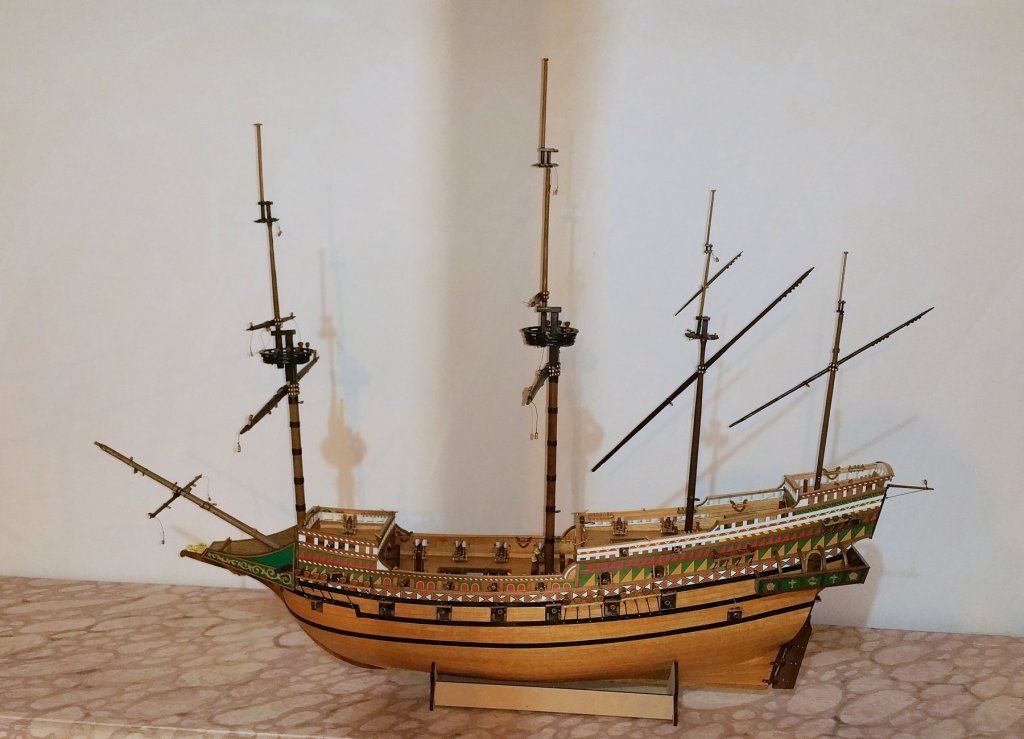
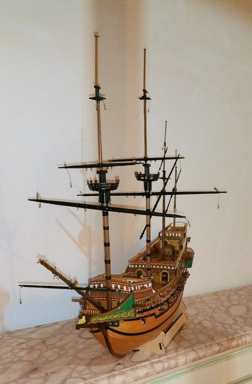
I now have the yardarms up and the masts fixed. The yardarms have some play in them (particularly the lateen yards), and they will get aligned during rigging. Now on to that! Best regards, David
-
On my computer, it looks like the pics above loaded out of sequence. The intended sequence is 1, 4, 3, 2.
-
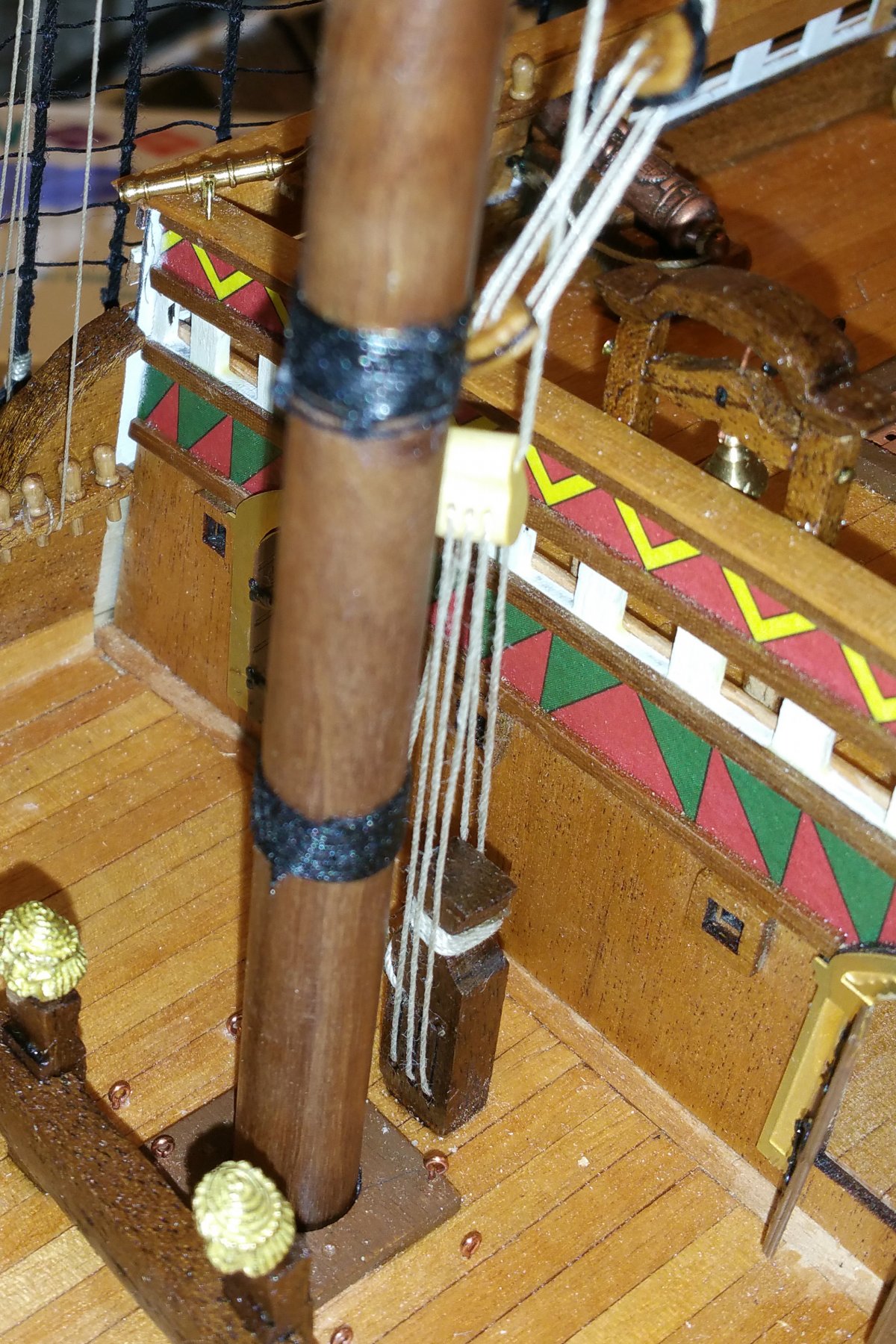
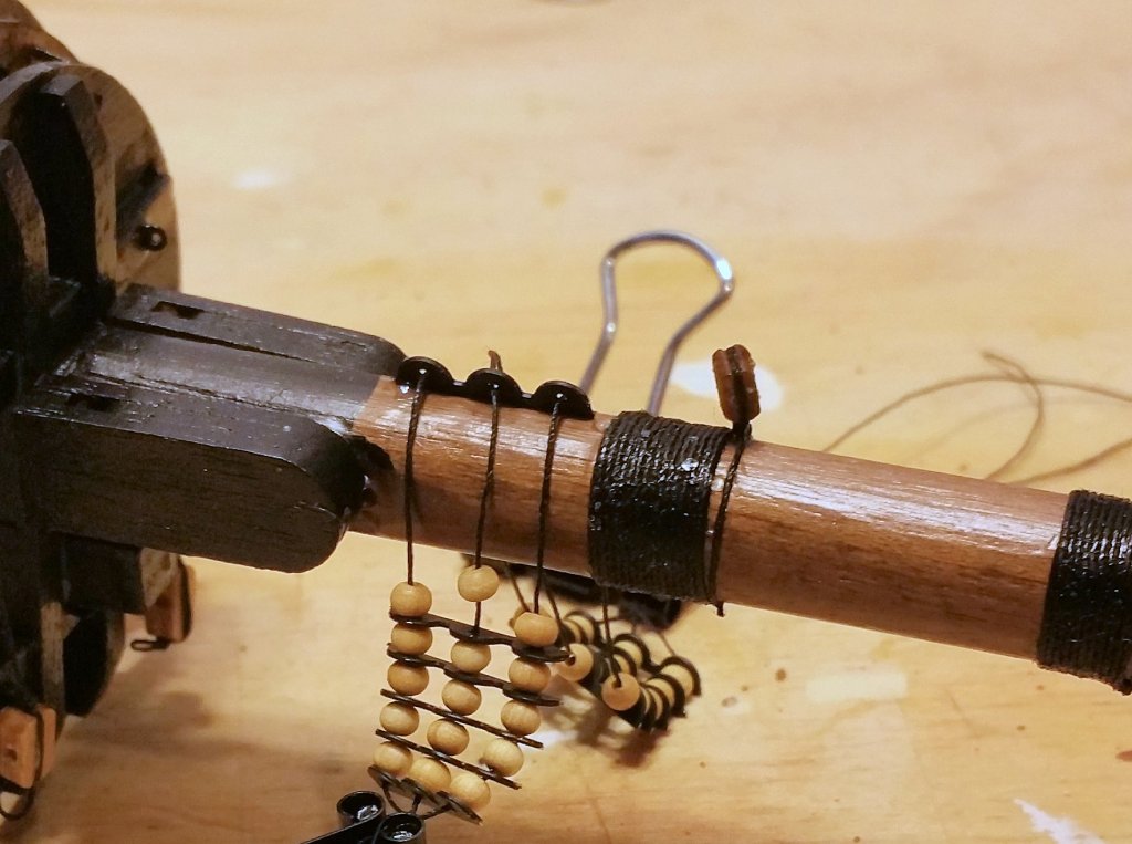
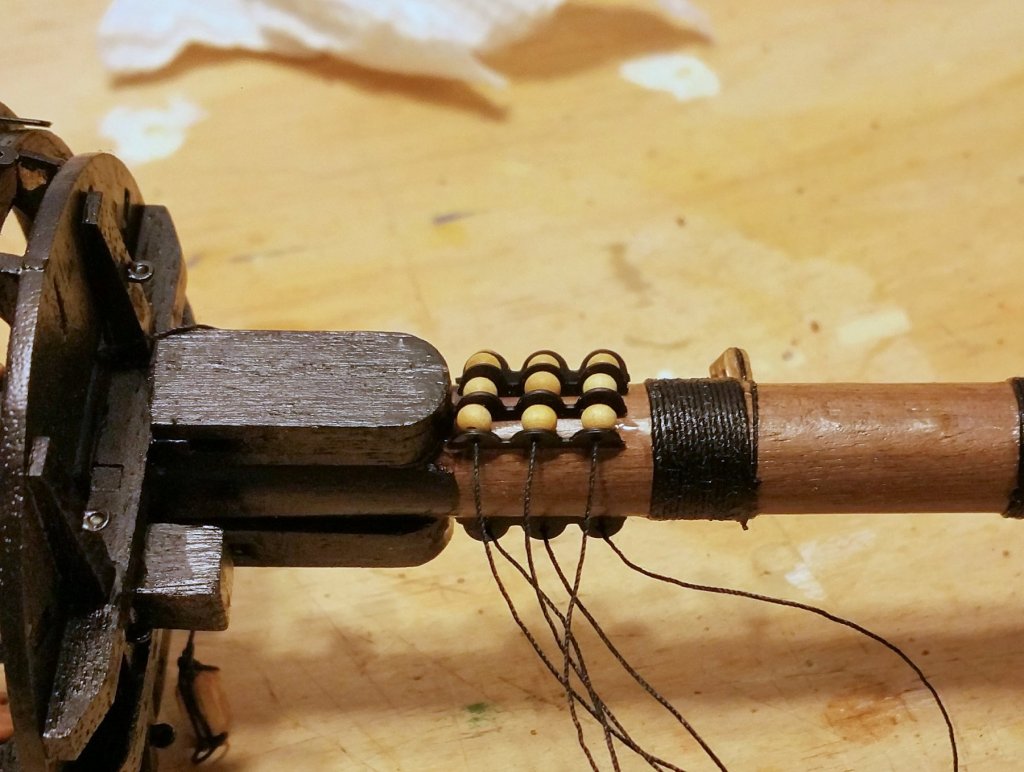
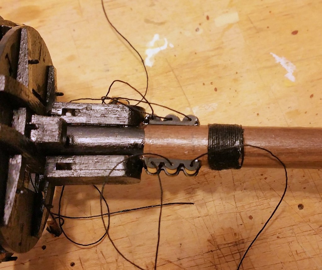
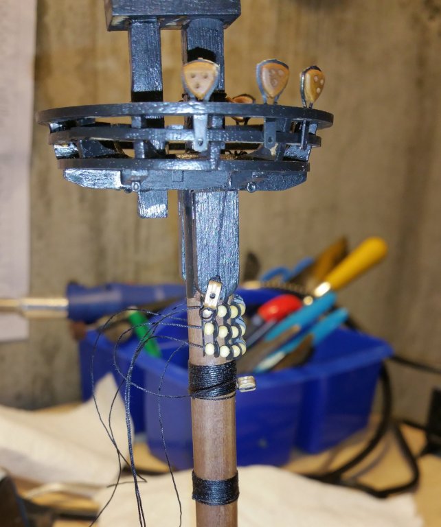
When I installed the first "parrel" on the main mast, it was really difficult because it's hard to keep the rib/bead assembly stable until you get some tension on the threads -- but it's hard to do that when the assembly isn't stable. The pictures below show a method that worked well. The number of ribs is odd, so I isolate the middle rib and glue it to the mast. That allows for the ribs/beads on each side to be snugged up and glued at the last rib. When that's done on both sides, the parrel assembly is stable and fixed to the mast, ready for tying on the yard. By the way, the drawings show an 11 rib assembly (two-tier) for the upper main mast yard, but that's too much for the diameter of the upper mast. I found that seven ribs worked well for that. Best regards, David
-
Thanks, Ondras. The largest yard will also have two yard lifts attached, and those will be heavier thread. All of the yards will have lifts attached of varying sizes. Best regards, David