drobinson02199
-
Posts
1,079 -
Joined
-
Last visited
Content Type
Profiles
Forums
Gallery
Events
Everything posted by drobinson02199
-
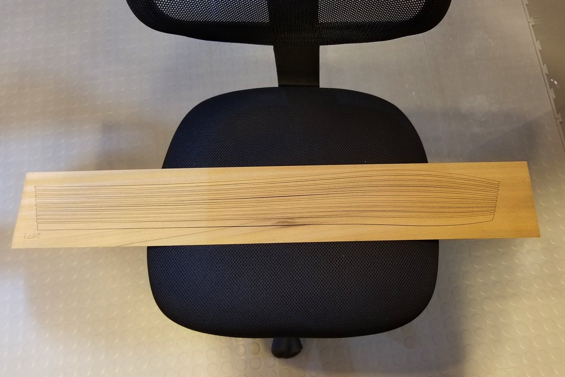
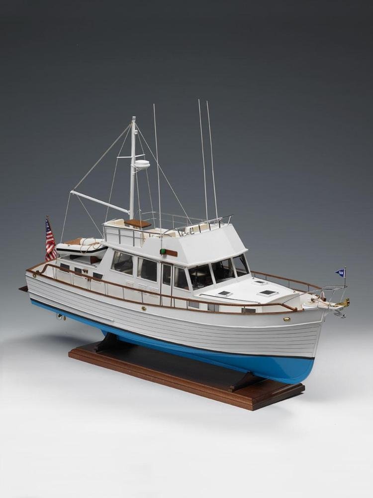
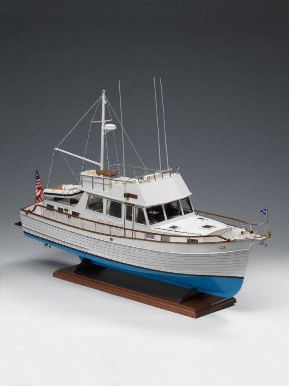
 I haven't finished all of the detail work on the superstructure, but the manual wants me to turn to the hull now. It gets planked and painted. Interestingly, the hull planking is laser cut to fit. See picture below. I think they did this because if you look at the Amati stock photo that follows it, the plank lines are meant to stand out after painting and be smooth and even, so that requires precise plank shapes. So no sideways plank bending!!! Now I just need to not screw it up. Regards, David
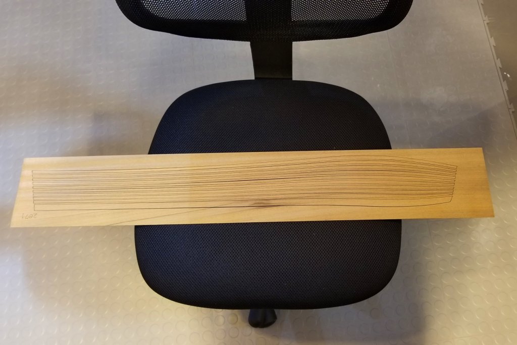
-
Antony: Hadn't heard from you in a while -- glad to see you back. She is just beautiful. I am totally in awe of you having done this as a scratch build. The detail is amazing. Regards, David
- 99 replies
-
- 4
-

-
- turtle ship
- korean
- (and 1 more)
-
Chris: Thanks -- I am really enjoying this one. I'm not really close to the end. Still a lot of detail to do: example is the bow railing I just installed on one side -- shown in the picture below. There is also more detail on the boat, the planking of the hull exterior and painting, hull deck planking, and other finish. I'd say I'm somewhere between 1/2 and 2/3 done. Regards, David

-
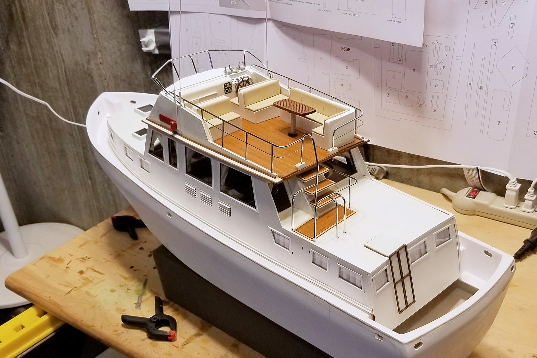
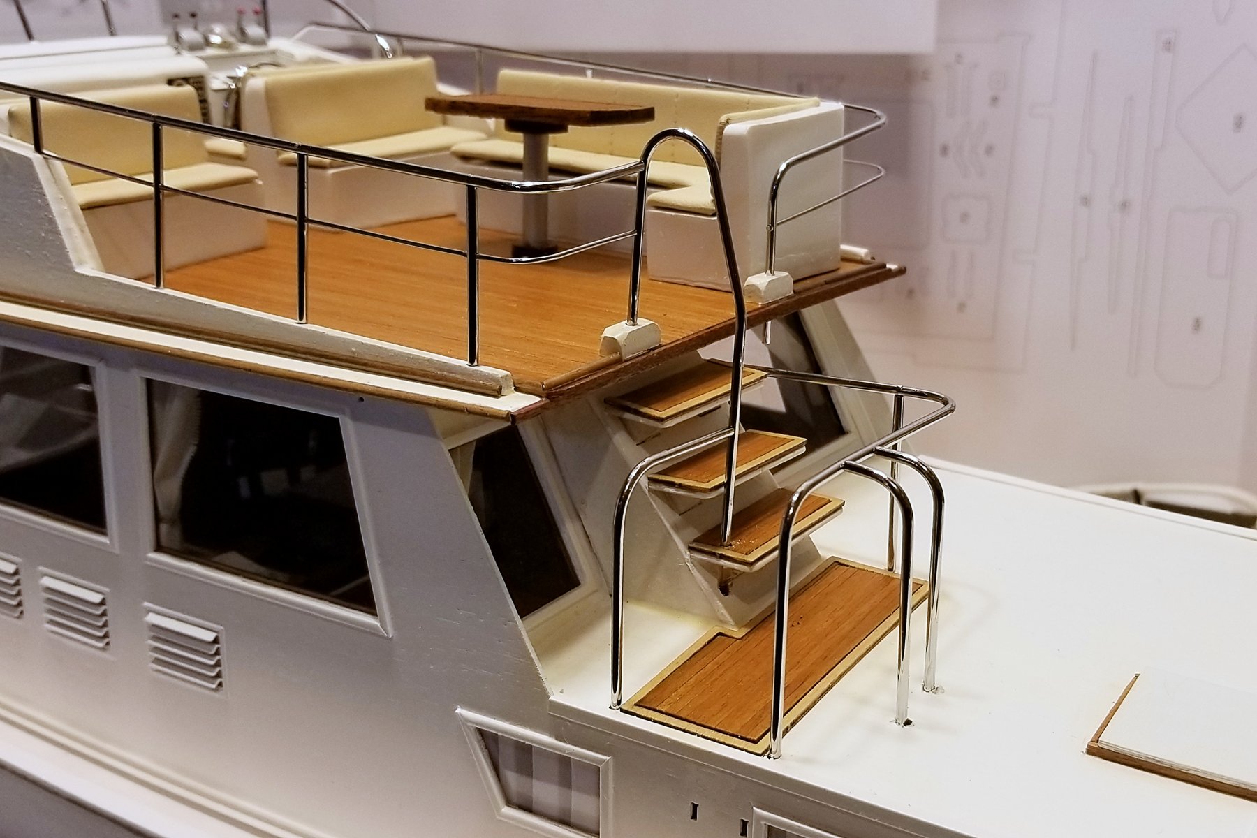
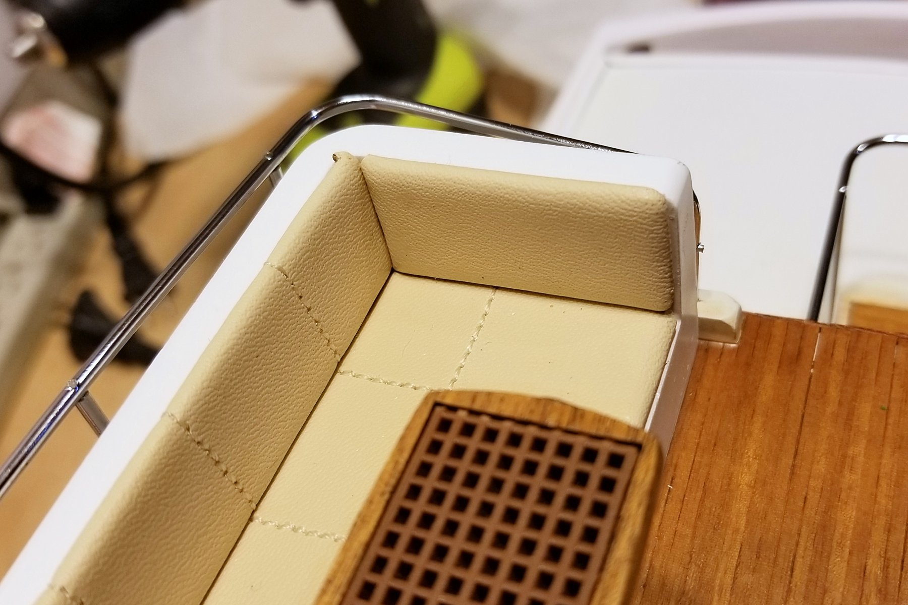
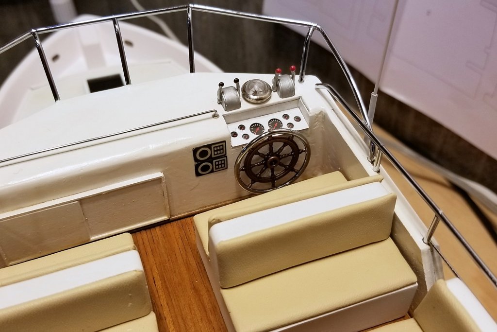
I finished the flying bridge fixtures and details today. Pictures below show the full flying bridge, the controls that duplicate the ones in the main cabin (as they would on the real boat), and the rear steps and railings. The flying bridge is still fully removable to see the main cabin interior. There is a closeup of the corner couch. The shorter seatback cushion was too long in the kit, so I had to undo the upholstery at one end, shorten it, and then re-cut and redo the upholstery. I think it came out well, and now I have another possible vocation in case my day job doesn't work out. Regards, David


-
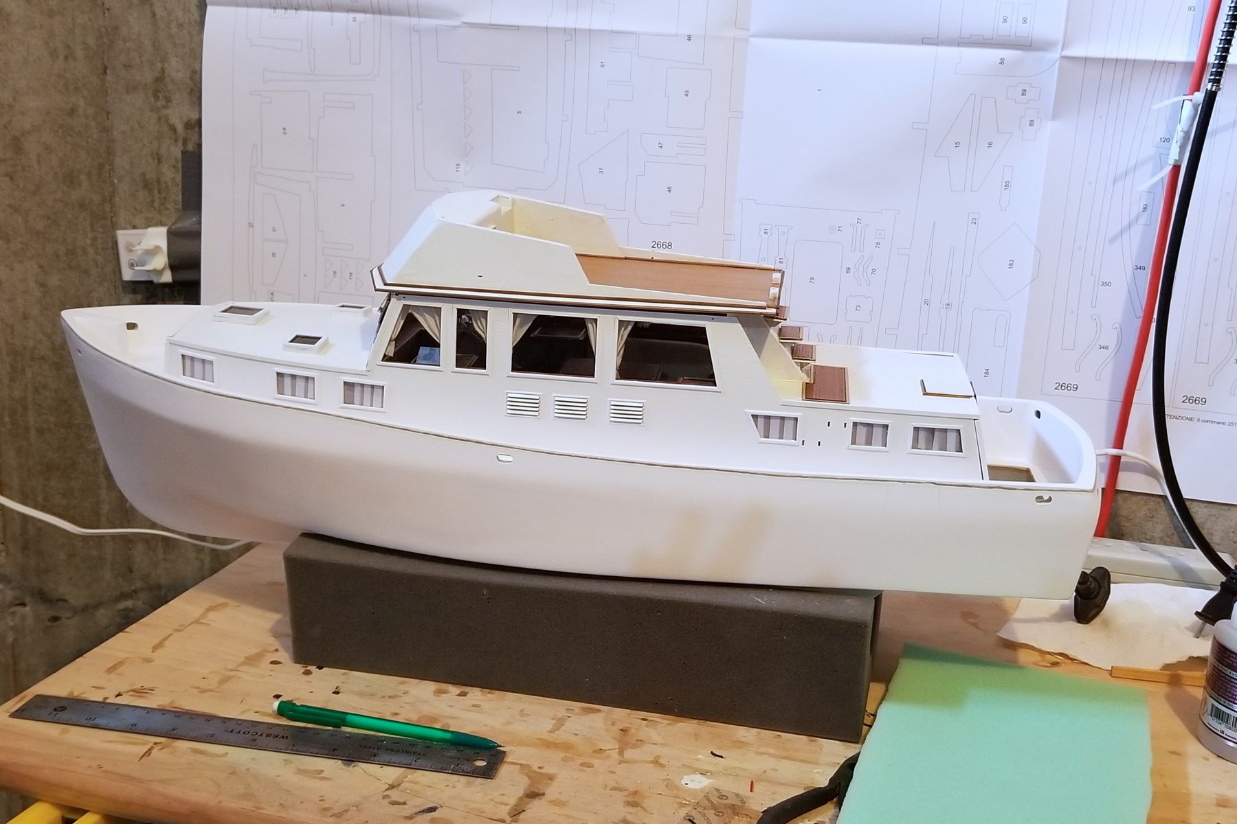
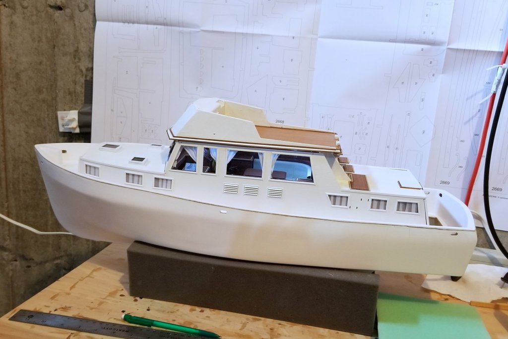
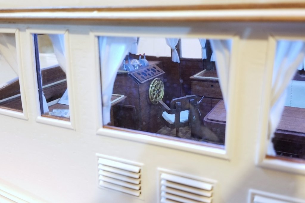
Back from vacation, and I fabricated some interior lighting for the boat (not part of the kit). Pics below show a full shot of the boat without, and then with, the lights on. Then three interiors taken through the windows with the lights on. Finally, the light and battery assembly on the bottom of the removable flying bridge. Regards, David


-
Chris: So sorry to hear about your health issues -- here's hoping that all will be figured out and you'll be on the mend quickly. Regards, David
-
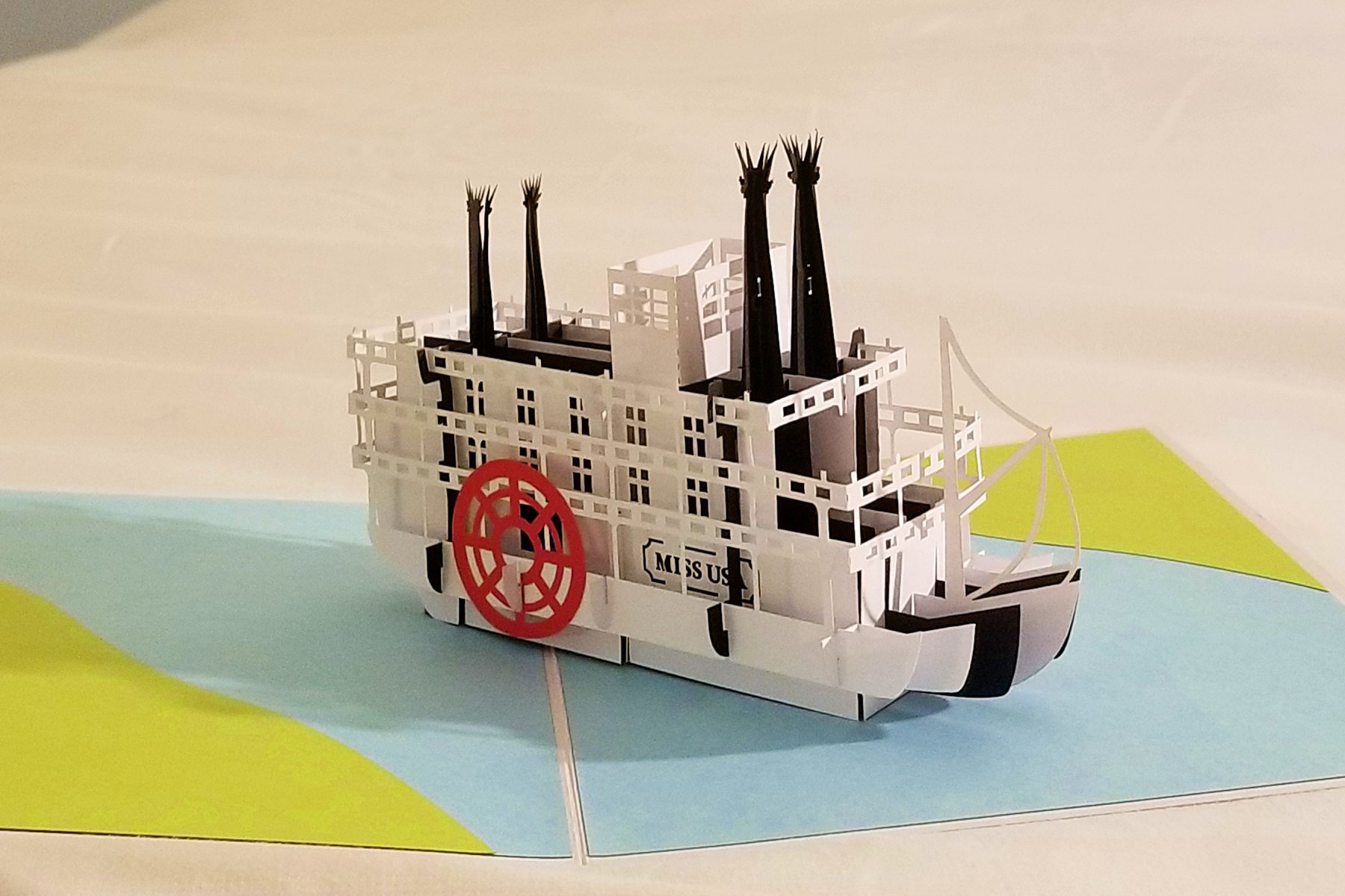
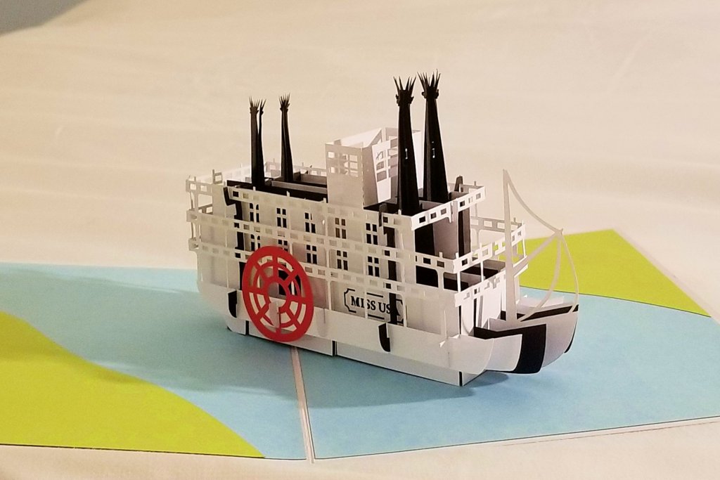
Chris: Given your focus on riverboats, I thought you'd appreciate this anniversary card my wife gave me. Regards, David
-
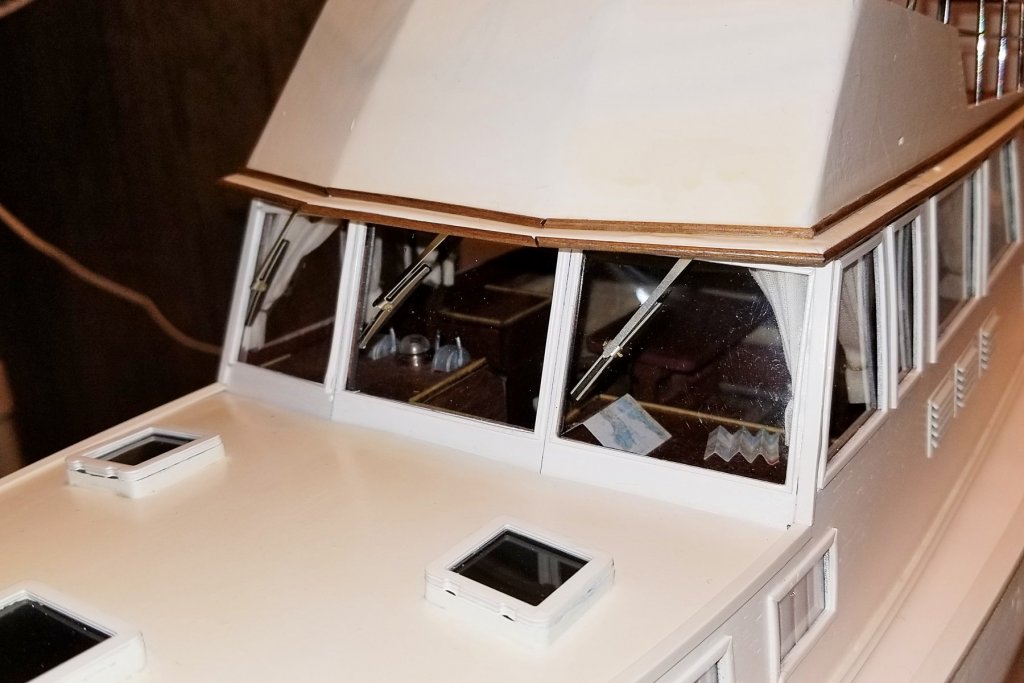
This will be my last progress report for two weeks as I'm going away with my wife from cold Boston to a sunny place. I have now planked the flying bridge deck. In this picture I also dry-fitted the main railings, although they won't go on permanently until the flying bridge furniture and fixtures are done. Note that the forward railing is missing a stanchion on the starboard side -- I broke it while fitting the railing and will need to glue it back on when the railing is permanently mounted. (This despite a manual warning to be careful as the forward railing is delicate). When drilling the holes for the forward railing, when you hold the railing over the bridge, it looks like the positioning of the first two holes as specified in the manual is a mistake, but it turns out that the angle of the stanchions makes for deceptive positioning. So followed the manual and it worked. Then I have also made and installed the windshield wipers, which I think are very realistic-looking. More building later in February when I return. Regards, David
-
Chris: On my riverboat, they put a water trough against one wall -- so you could consider that. Easy to fabricate. Regards, David
-
Chris: Those figures, along with the detail you've put into the horse bay, are really great. It's looking terrific. Did the link I sent you help with your search for horses? Regards, David
-
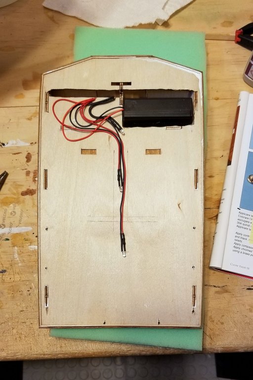
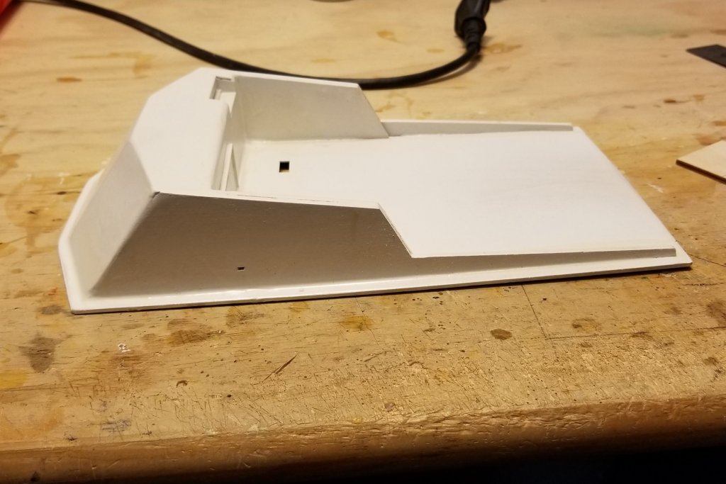
I'm about to begin work on the flying bridge, and with the interior cabin finished, I realized that while the flying bridge is removable to view the interior cabin, it might be good to light the interior. I can do that by attaching led's to the bottom of the flying bridge. There is room to make a cavity for the battery and switch, which you can see in the pics below. Would have bee much harder to do this if all of the railings and finish had been applied to the flying bridge. Regards, David
-
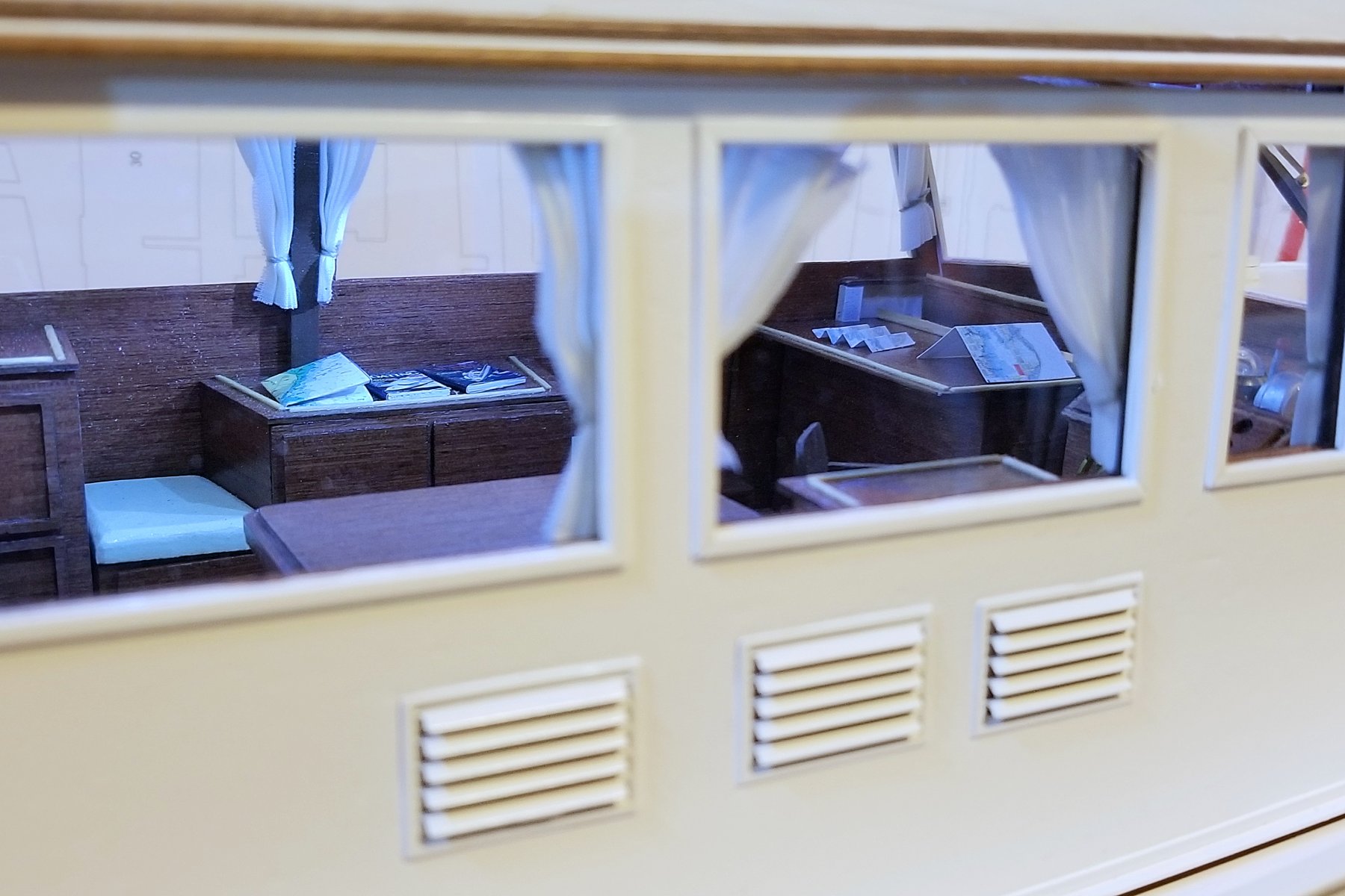
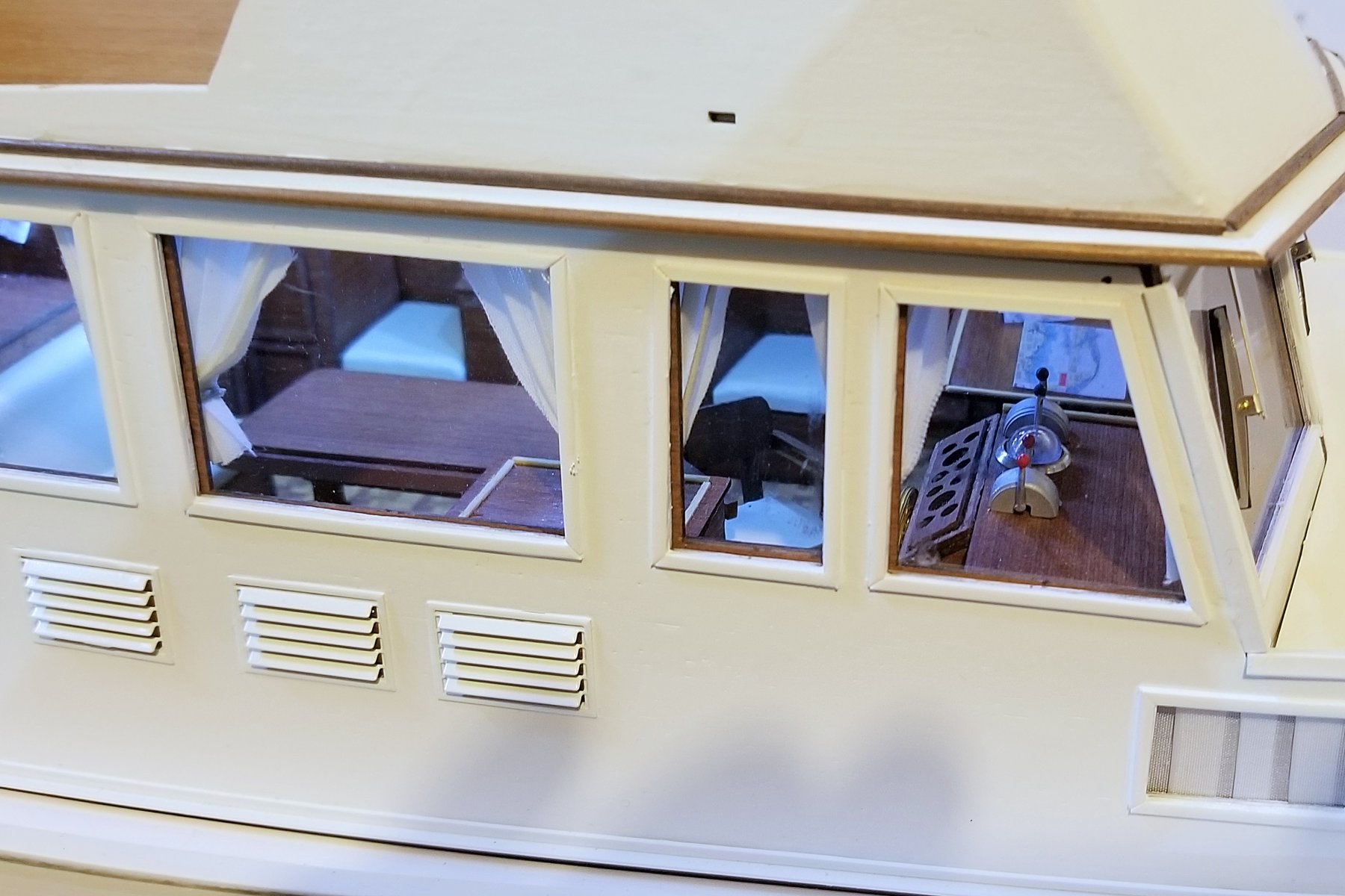
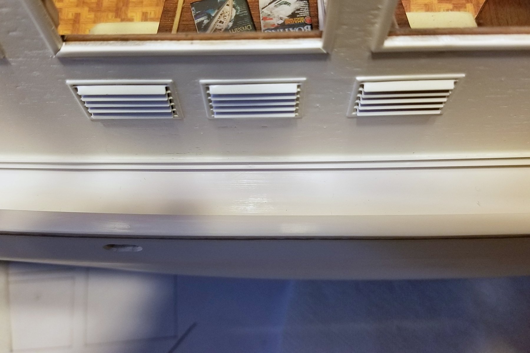
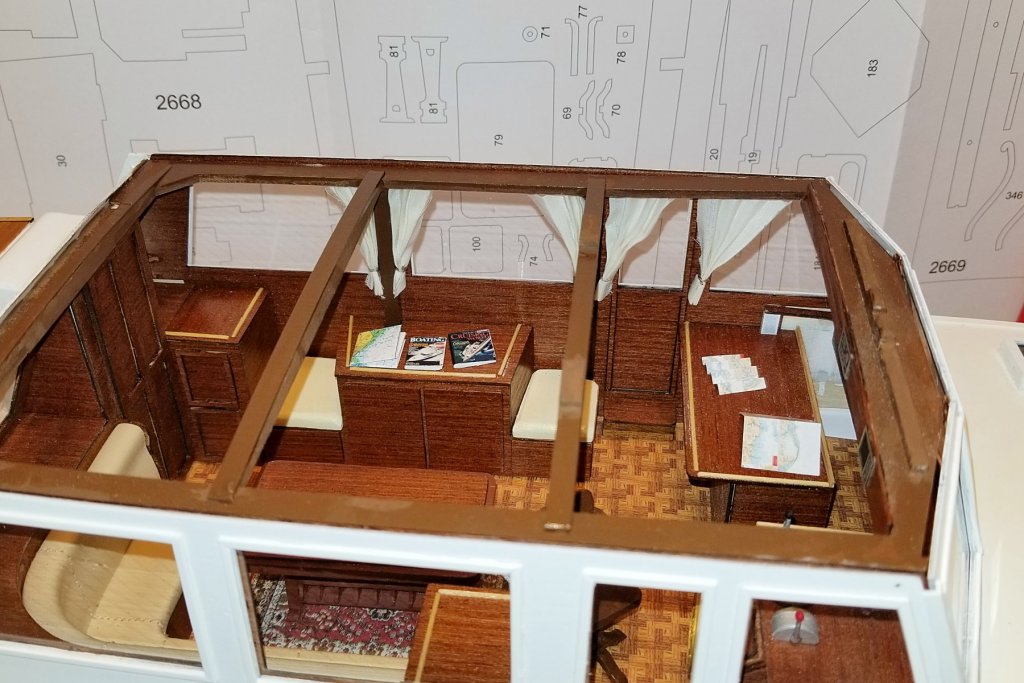
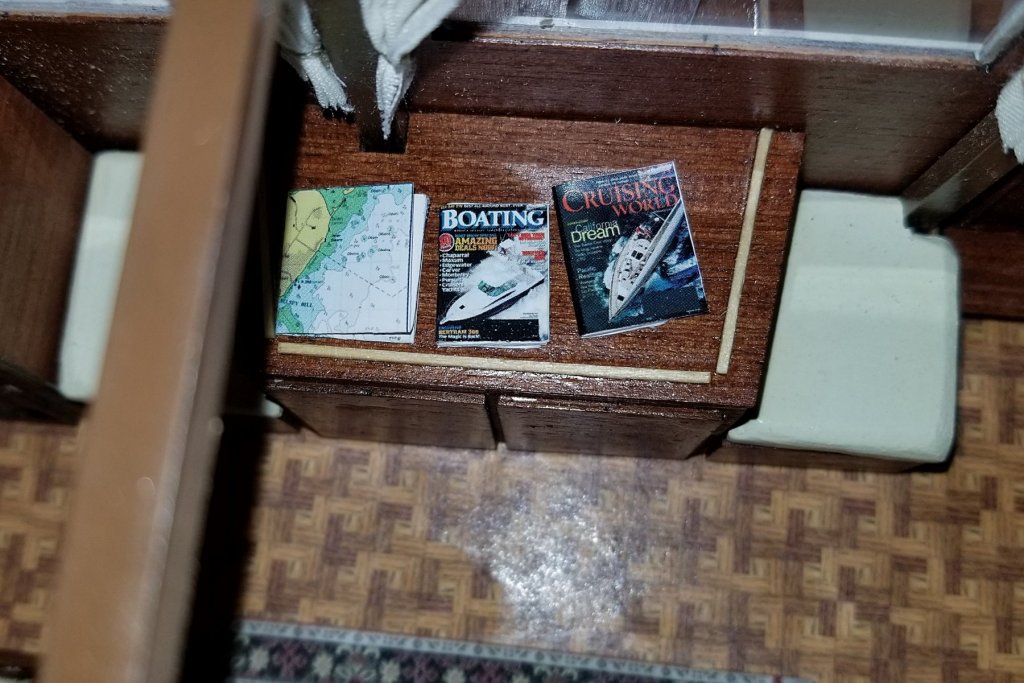
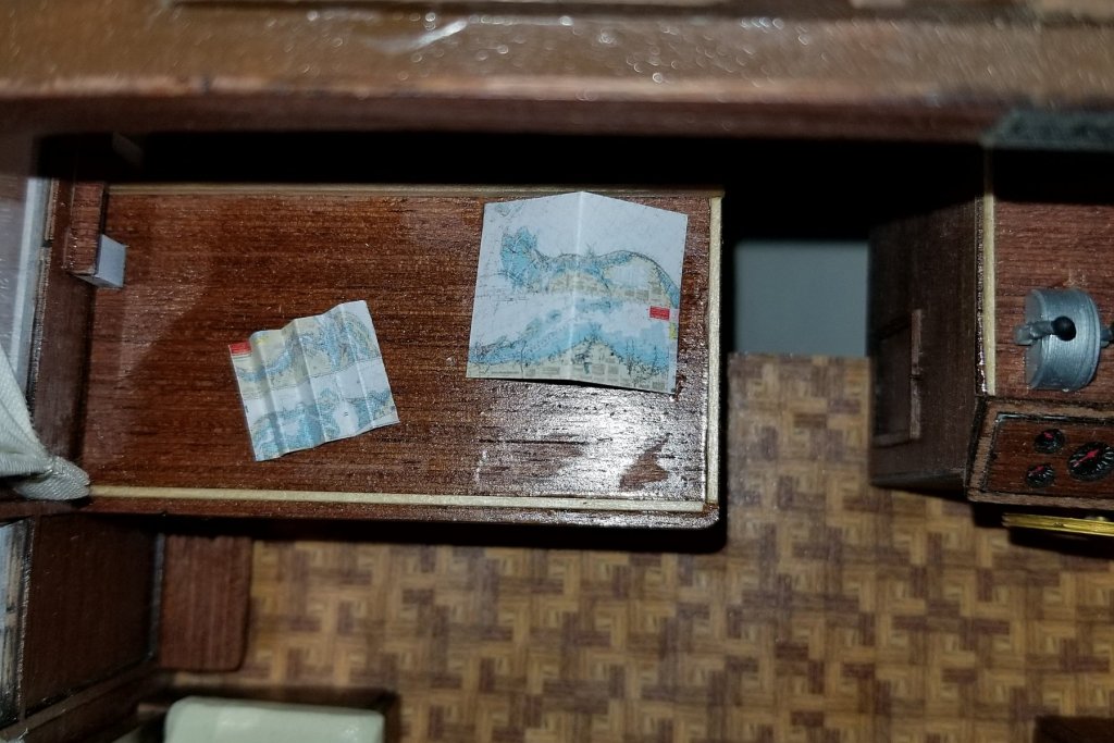
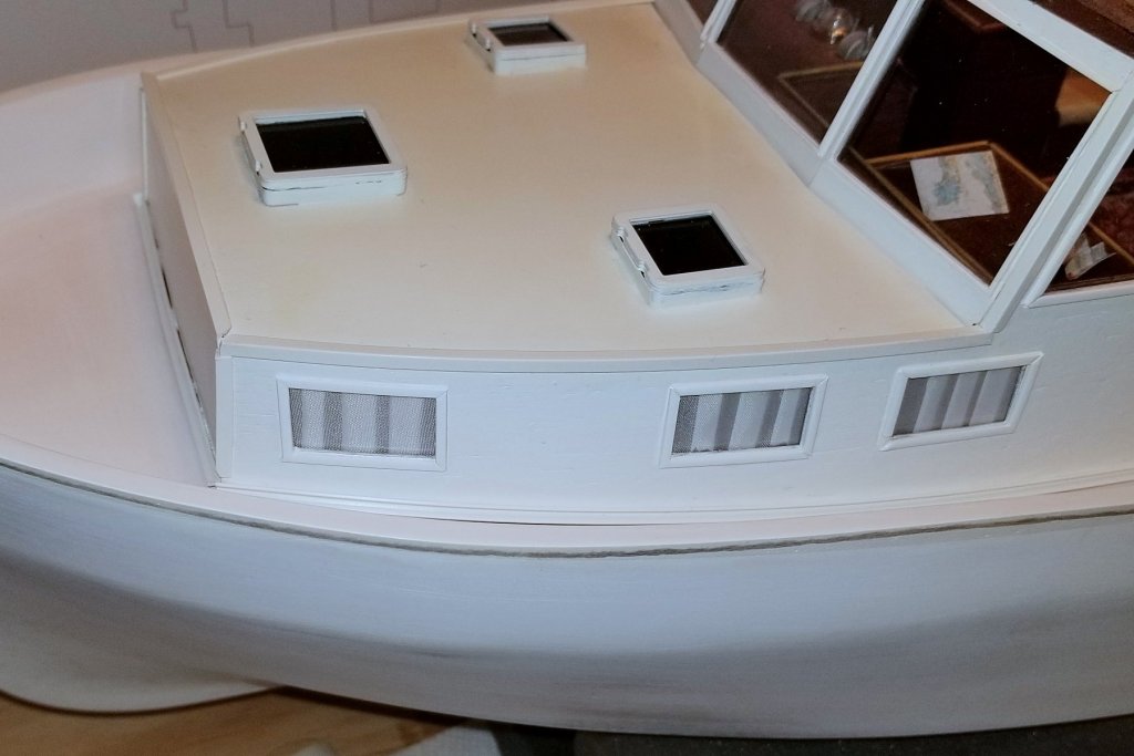
Finishing off the main cabin interior. First picture shows the curtains up, as well as the magazines and maps. Closeups of those follow -- they are real mag covers and real maps, all reduced to miniature in the kit. A build tip: the instructions call for the curtain cloth to be sized with diluted PVA glue to give them some body, but that didn't do the trick -- after folding they were too floppy. So after folding and tying, I used hair spray to stiffen them. The bow picture shows the moldings covering the join points. The final picture shows the molding reversed to act as a flashing where the sides meet the hull deck. A build point: looking ahead in the instructions, the hull deck is made up of a 1mm frame and 1mm planks, so when installing that flange, I needed to make sure I had 2mm underneath it all the way around. Regards, David

-
Don: The planking looks terrific. As to your deck, it's way above the average standard on my builds, and looks great to me. I know what you mean about finishing planking. Seems like it will never end -- until it finally does! Regards, David
-
Chris: The curved couches are made of some sort of "leatherette" material. The square ones flanking the table are painted wood. Regarding more interior detail -- stay tuned. There is another wave of interior detail coming, but I need to do some other steps first. Regards, David
-
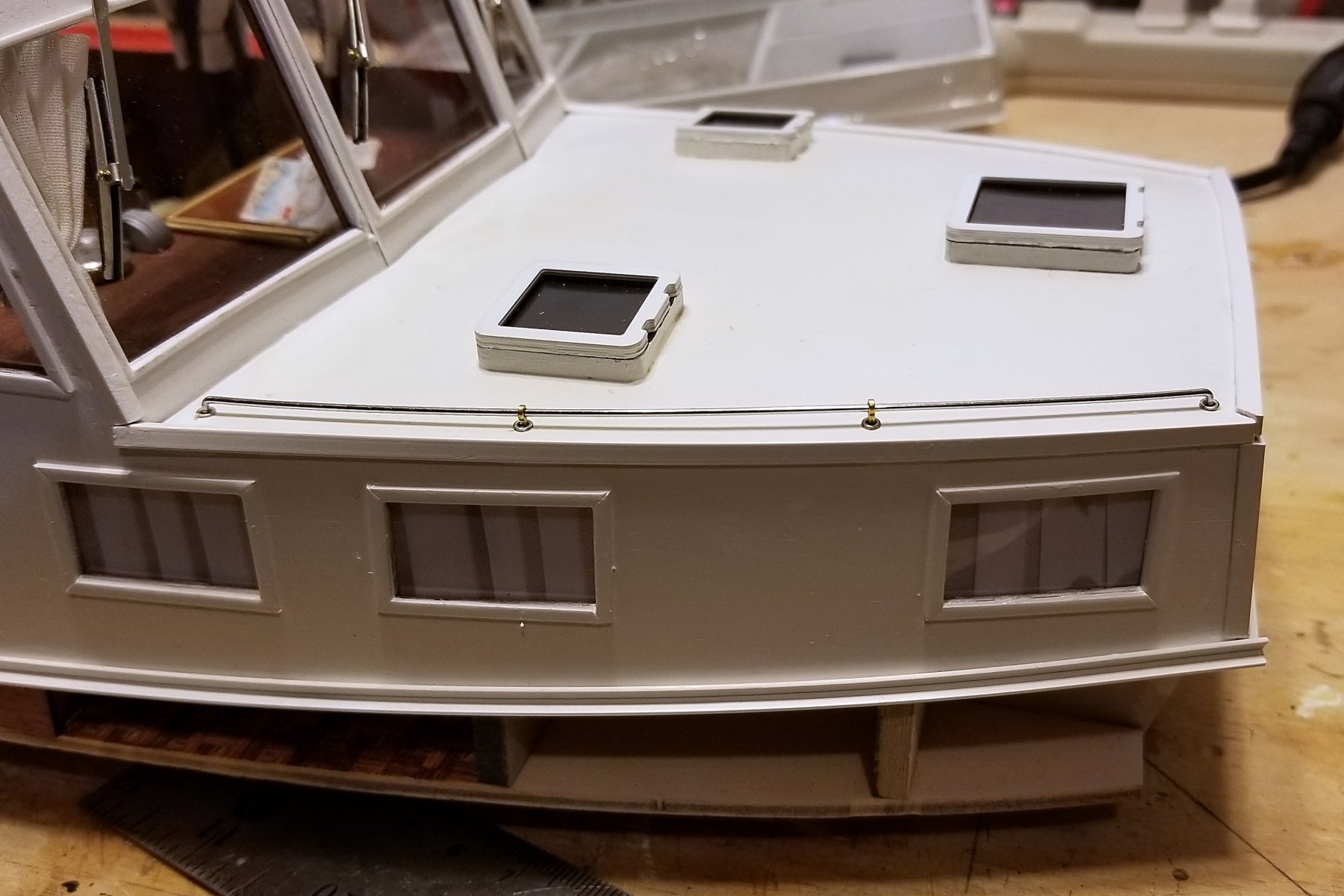
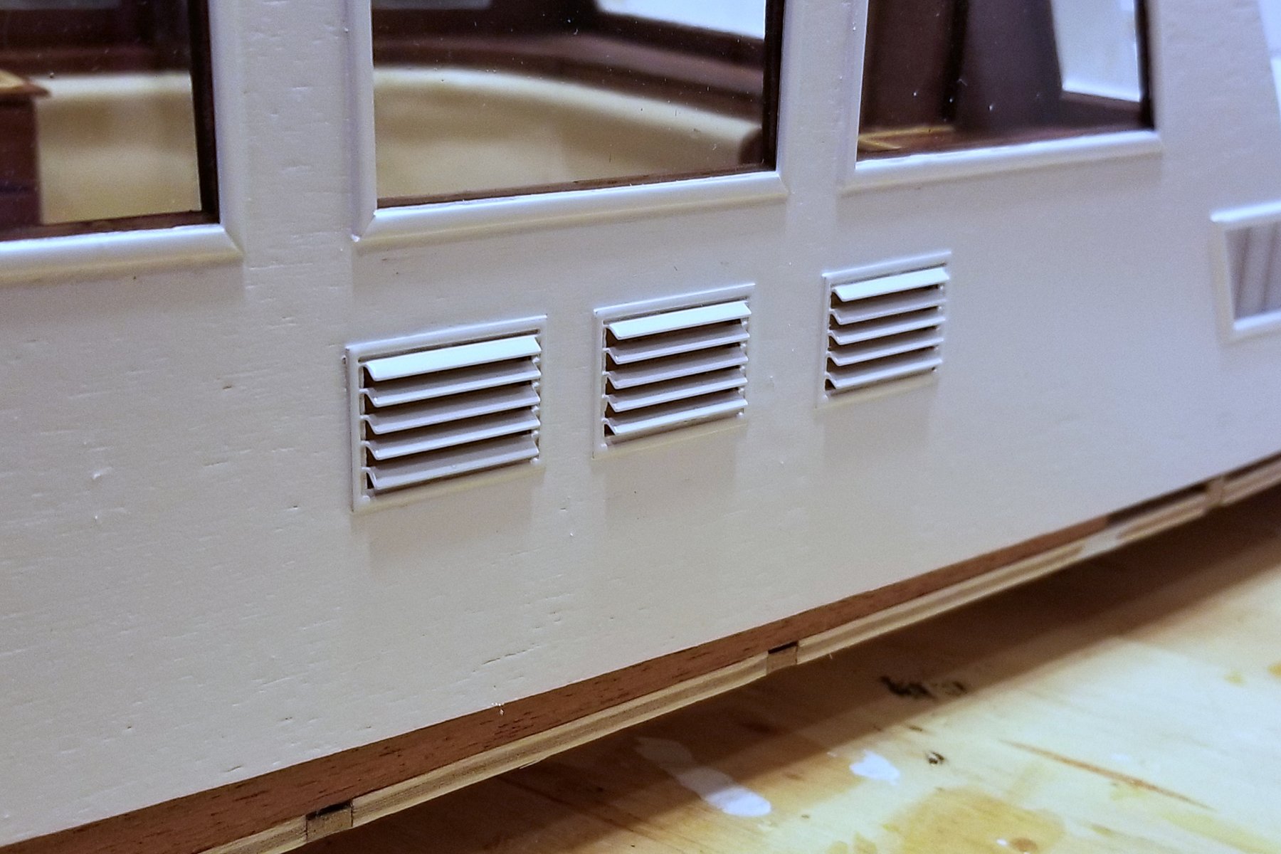
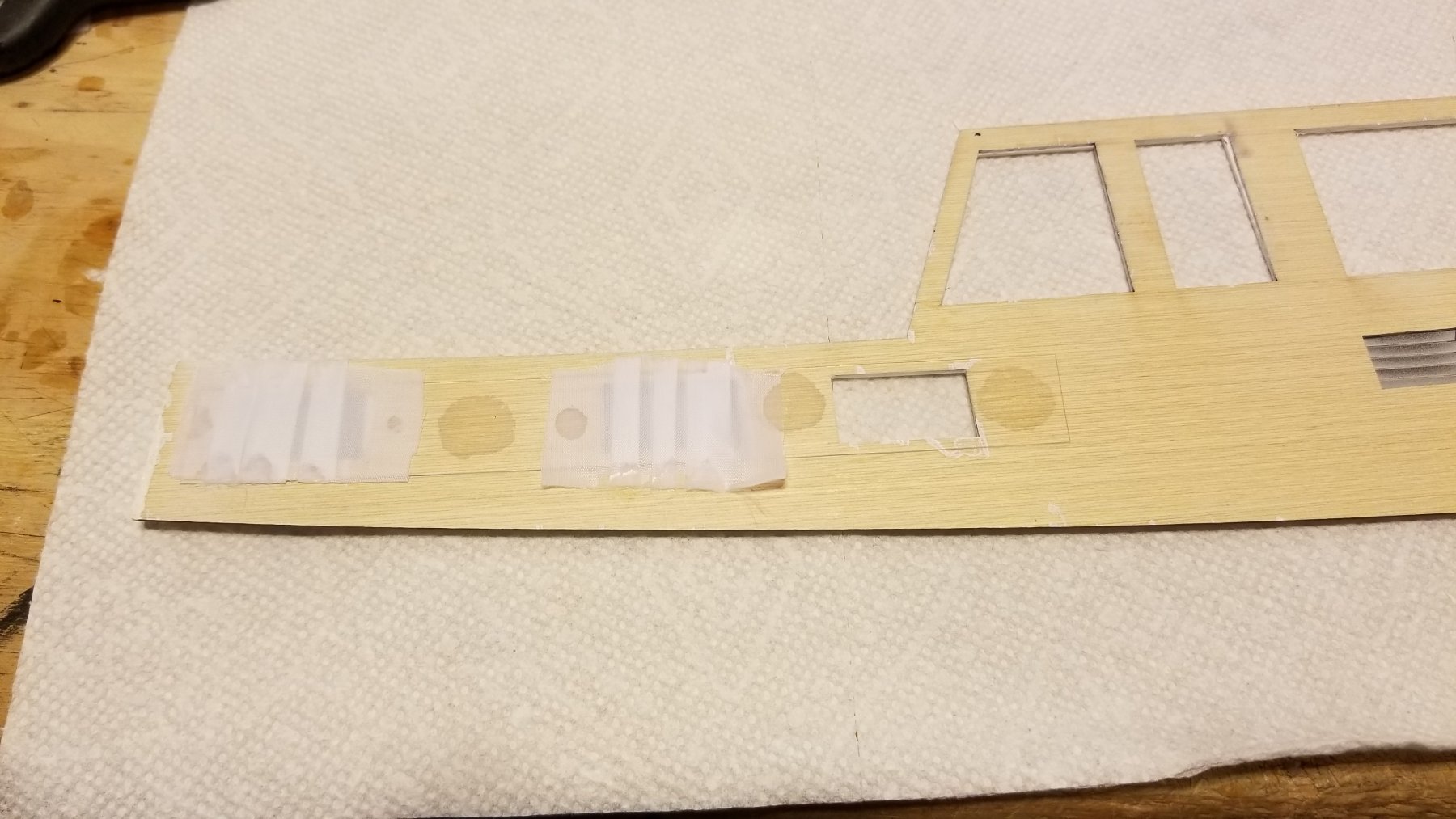
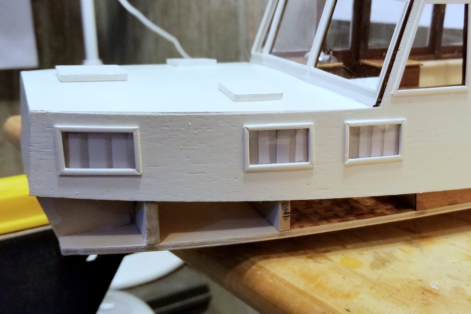
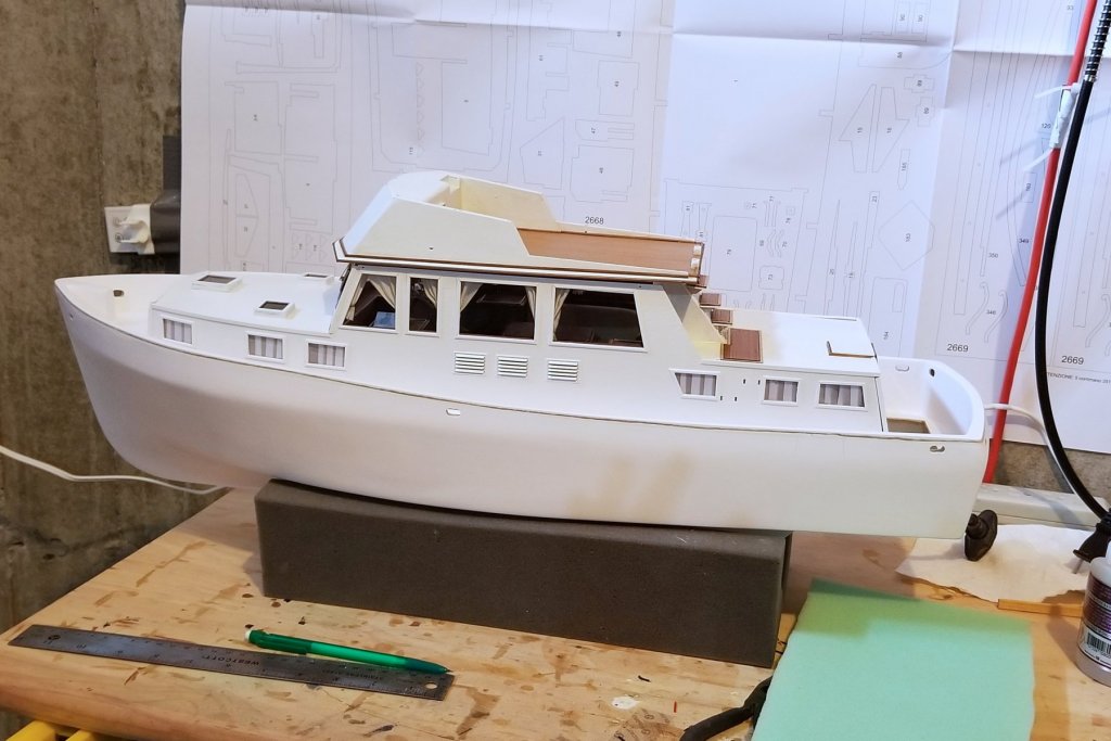
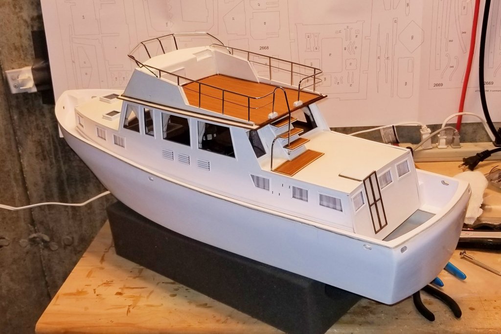
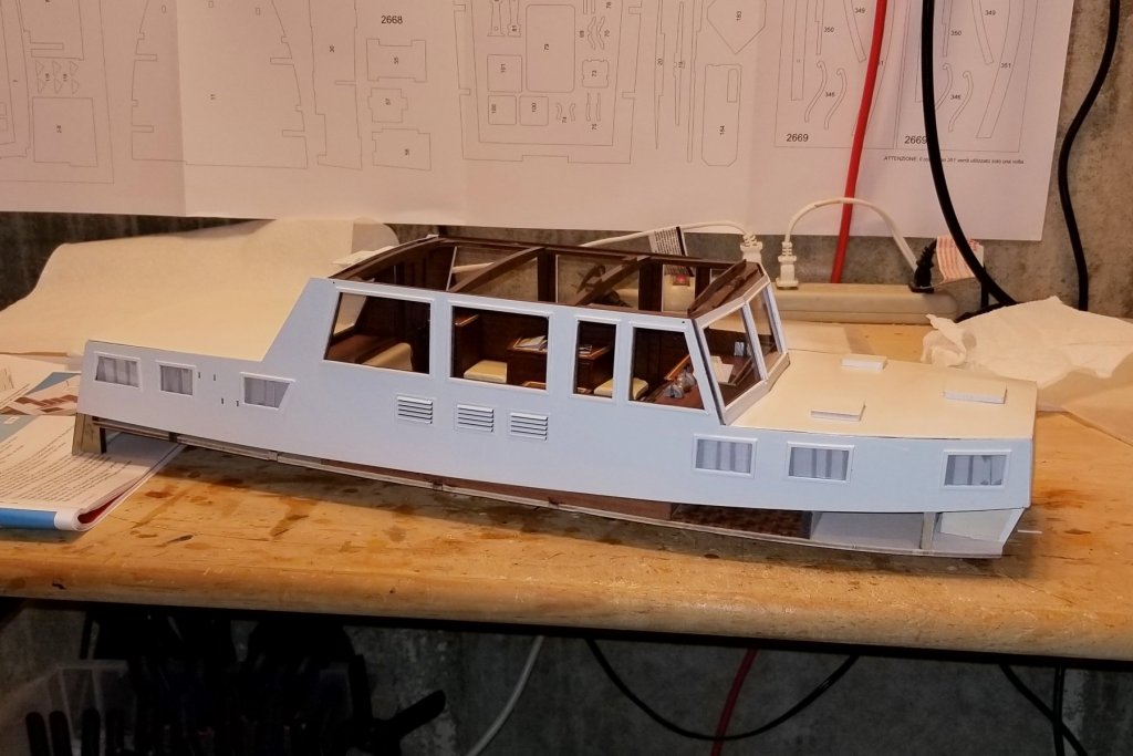
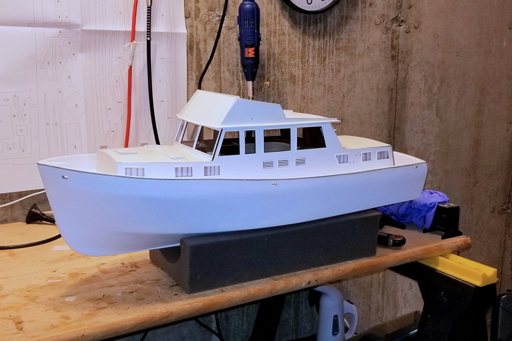
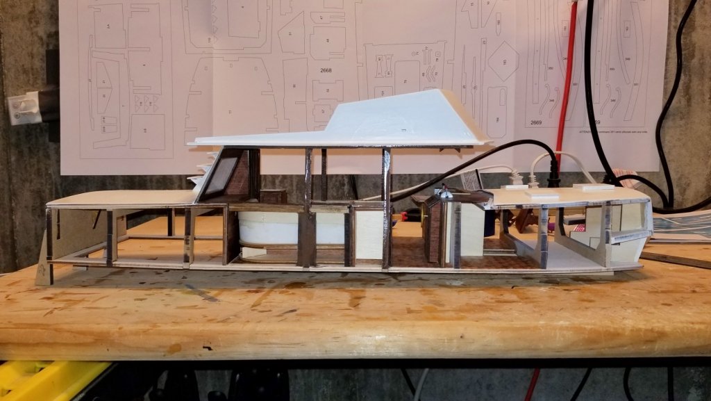
Finished the sides and mounted them on the boat. The first picture shows that with the superstructure off the hull. Note that there are moldings at all the deck and side joins that I haven't installed yet. There's a detail picture of the vents. Nice touch is the side curtains. The third picture shows how they are installed on the sides from the rear, and then there's a closeup of how they look from the front. Finally, there's a picture of the superstructure mounted on the hull, with the flying bridge mounted on top. The flying bridge will get a significant amount of finishing, but I'm not quite at that step yet. Regards, David


-
Another note. I mentioned above that the instructions incorrectly called for part 77 to be used as a bulkhead support, and wondered where it would be used. Turns out that part 77 (two of them) are the arms of the captain's chair. Regards, David
-
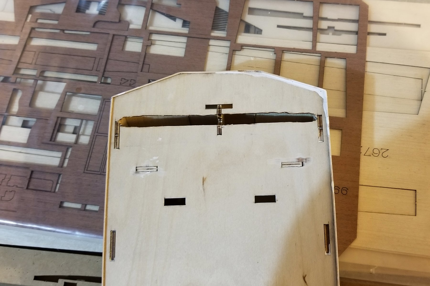
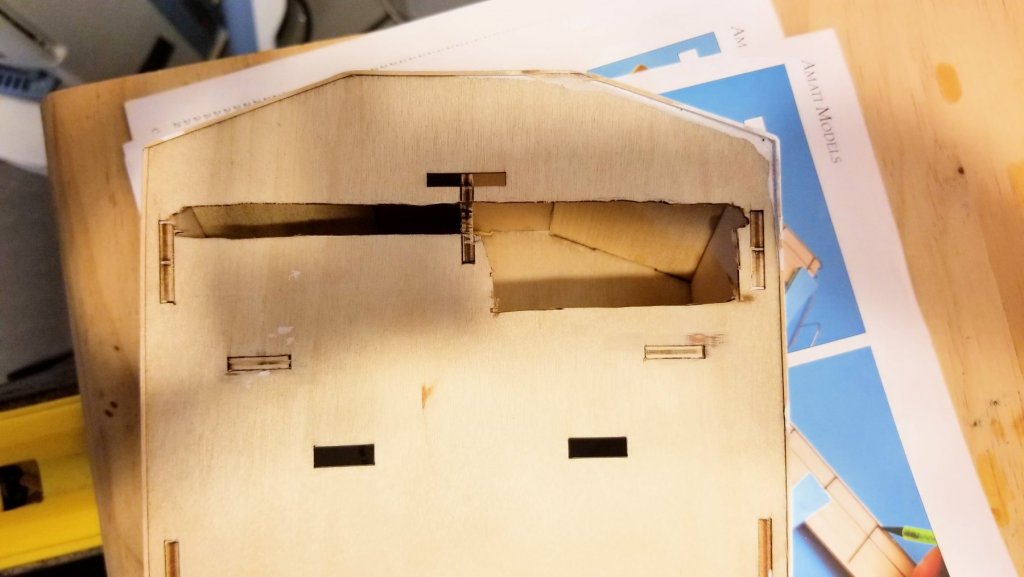
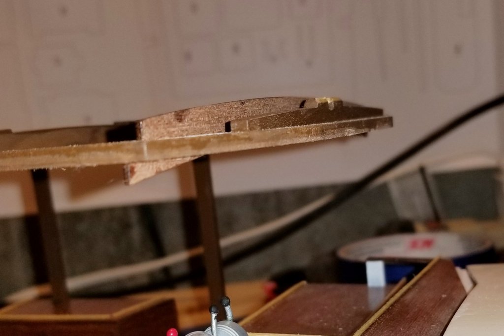
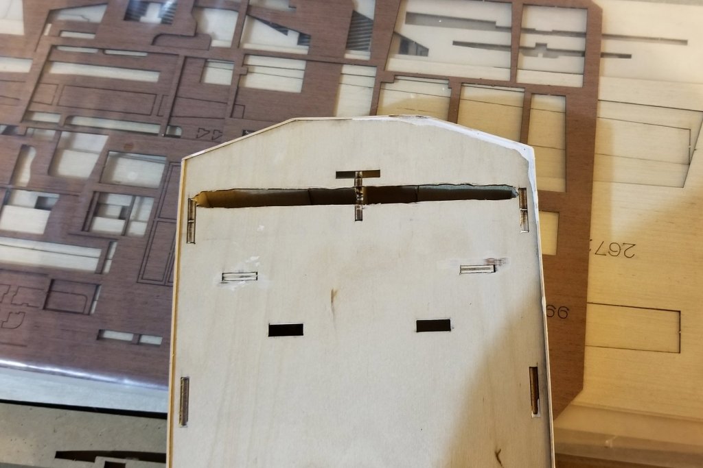
I ran into a problem after the last step. In the first picture below, you can see the beam that was added to the transom. Picture 2 shows that it sticks up above the flying bridge support bracket in front. That left the flying bridge tilted up and not fitting flat. The small instruments precluded sanding that beam down. So the solution was to cut a slot in the base of the flying bridge. You can't see those little instruments when the bridge is mounted anyway, so having them go partway up into the slot is no big deal. Now the flying bridge sits flat again. Regards, David
-
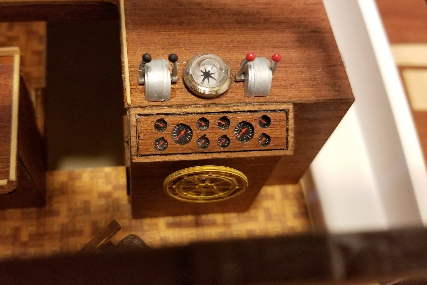
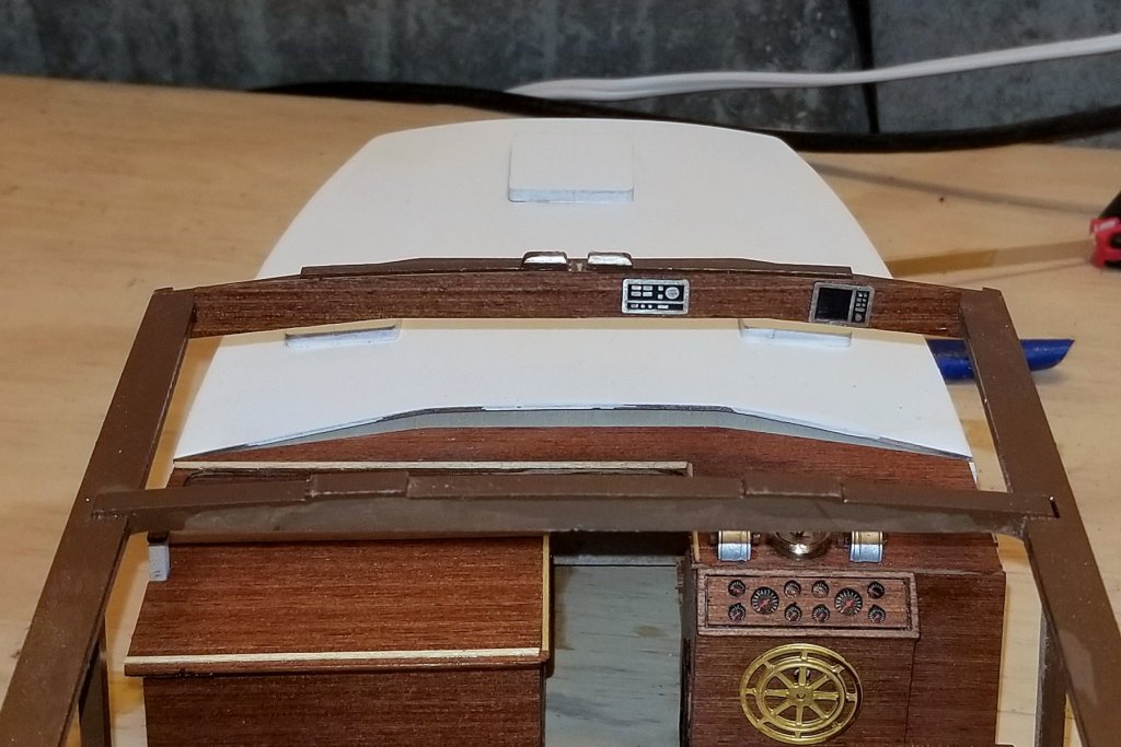
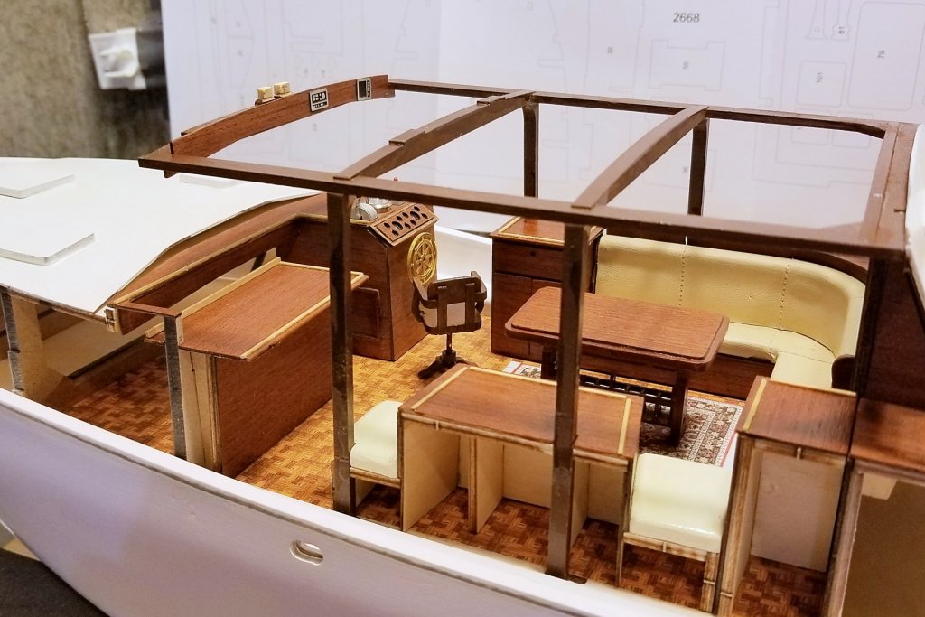
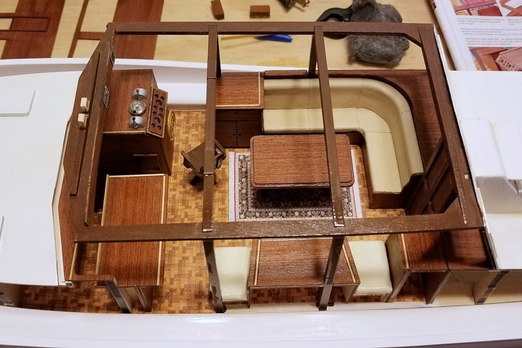
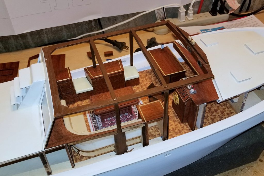
I have now finished the main cabin furniture and cabinetry. In the pics below, the superstructure is dry fitted into the hull, but the sides aren't on yet. Several views -- almost all of what you see is mahogany. I particularly like the instrument panel and controls. More when I get the sides on (which are also mahogany on the inside). Regards, David

-
Don: I've just caught up to this log, and your beech planking looks wonderful. I love the way you did alternating boards and lined up the joins. I'm going to sign on to see the rest. Regards, David Robinson (the "other" one)
-
Forgot to mention in my previous post: there's an error in the manual. In the second picture above, where you see the curved extension come to rest on one of two stub posts: the manual calls for those to be part 77, but that clearly doesn't fit, and in later pictures it morphs into the part you see here. Took some looking ahead to suss it out. I'm not sure part 77 is ever used, although it's marked as a "sofa part". We'll see. Regards, David