MORE HANDBOOKS ARE ON THEIR WAY! We will let you know when they get here.
×

Mike_In_RI
-
Posts
276 -
Joined
-
Last visited
Content Type
Profiles
Forums
Gallery
Events
Everything posted by Mike_In_RI
-
 'Sorry for my tardiness. I thought I could get the build done in the winter months but intentionally put more time into scale representation and got behind. But, it's quad-copter racing season now so I'm only working on the whaleboat during rainy days. Oars.... tubs... knot training, etc. ... I have not given up!!! Mike
- 128 replies
-
- 3
-

-
- model shipways
- new bedford whaleboat
- (and 1 more)
-
Well done, you should be very proud! Great attention to detail and it shows all the thought you have been put into it. Super presentation. Mike
- 165 replies
-
- 2
-
-
- finished
- model shipways
- (and 1 more)
-
That's a lot of rope coils! +1 for your patience. Also thanks for your tip regarding the xken logs. I checked it out and it's very useful to me as you said regarding "small stuff" technique. Mike
- 165 replies
-
- 2
-
-
- finished
- model shipways
- (and 1 more)
-
Thanks Buck, I just checked your Morgan whale boat build. The miniature parts are great. I especially like the brass screws for the mast tabernacle. I may have to "pirate" that one! Mike
- 128 replies
-
- 2
-
-
- model shipways
- new bedford whaleboat
- (and 1 more)
-
Thanks Steve, I appreciate the comments. These little parts are more suited to my eyesight when I was 16 . I'll check out Ken's logs ... thanks for the tip. Mike
- 128 replies
-
- 1
-
-
- model shipways
- new bedford whaleboat
- (and 1 more)
-
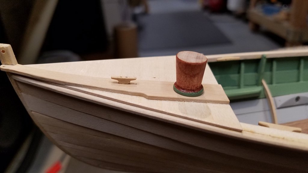
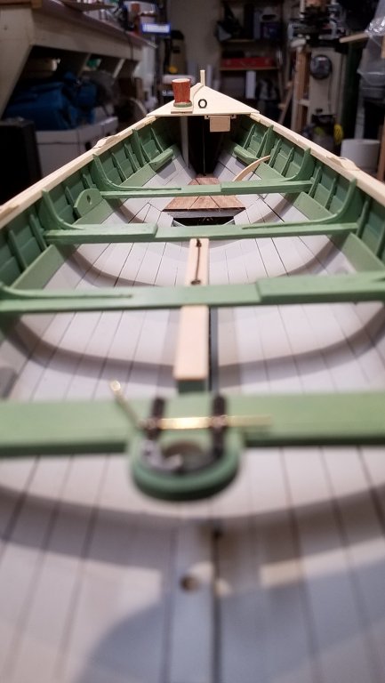
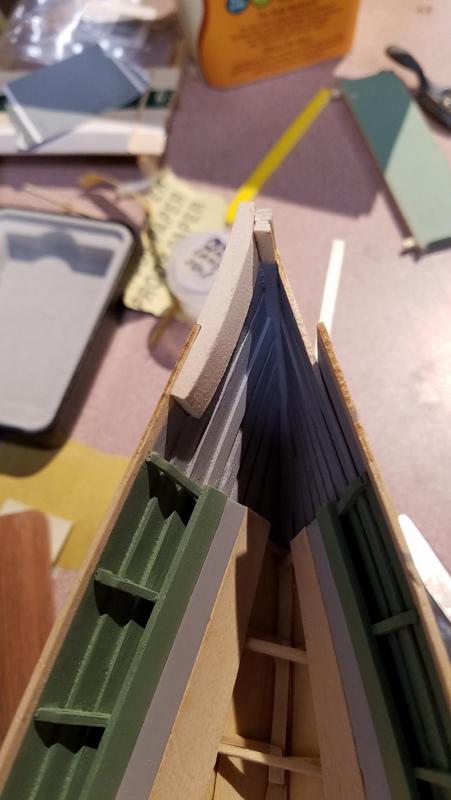
I've been a little outside my comfort zone this week practicing brass wire bending and solver soldering. I bought a forum suggested book by Ken Foran "Model Building with Brass" which helped me out on the basics and really got me going. However, for me, I need something a bit more practical i.e. handling small pieces, fixturing, etc. Any suggestions will be greatly appreciated. The bow and stern fixturing is complete. I've really gotten to like the 1/32" and 1/16" boxwood sheets I bought and am now using it on all small parts of those thicknesses. In this weeks work, I used it on the ore lock pads, centerboard case caps, cleats and lions tongue. Here is a shot of the loggerhead post. Per the build log, I made the cross section octagonal. But the plans call for a square post with beveled corners so I may re-do that. The loggerhead was turned in the lathe and made from maple scrap. There are 3 coats of cherry stain applied so far and I will put on a few more coats to get it a little darker. The three cleats are glued and pinned with ~ .020" steel pins. The rowlock pads will have simulated cast iron sockets using silver soldered strip brass and tubing. This shot is focused looking to the stern from the harpooners thwart. The inner hull painting should be finished soon while the rudder and its parts are next in the queue. As usual, any comments, corrections and questions are welcome. Mike

- 128 replies
-
- 7
-
-
- model shipways
- new bedford whaleboat
- (and 1 more)
-
Wow, lots of progress since my last visit. It sure is super looking. Mike
- 165 replies
-
- 2
-
-
- finished
- model shipways
- (and 1 more)
-
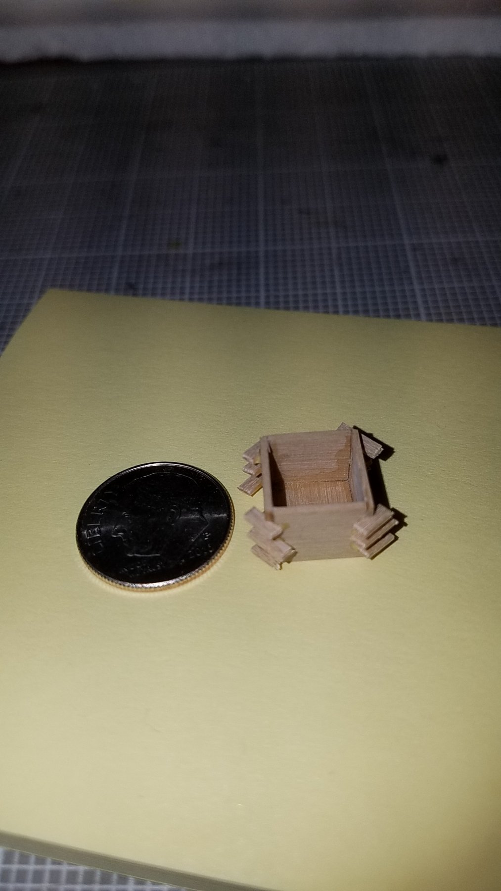
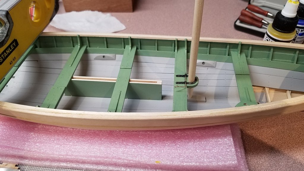
In between brush coats of paint on the thwarts, I've been working on more small parts. Also, the bow chocks have been added. I assembled the cuddy boards while off the model in order to do a neater job on the compass box attachment. ... just making sure there is a little back rake in the mast. The compass box is make from 1/32" boxwood. I really like it for the small parts. The stem joinery not including the clumsy cleat and bow chocks are also boxwood. .... next comes the loggerhead and attachment of the cuddy boards. Mike

- 128 replies
-
- 6
-
-
- model shipways
- new bedford whaleboat
- (and 1 more)
-
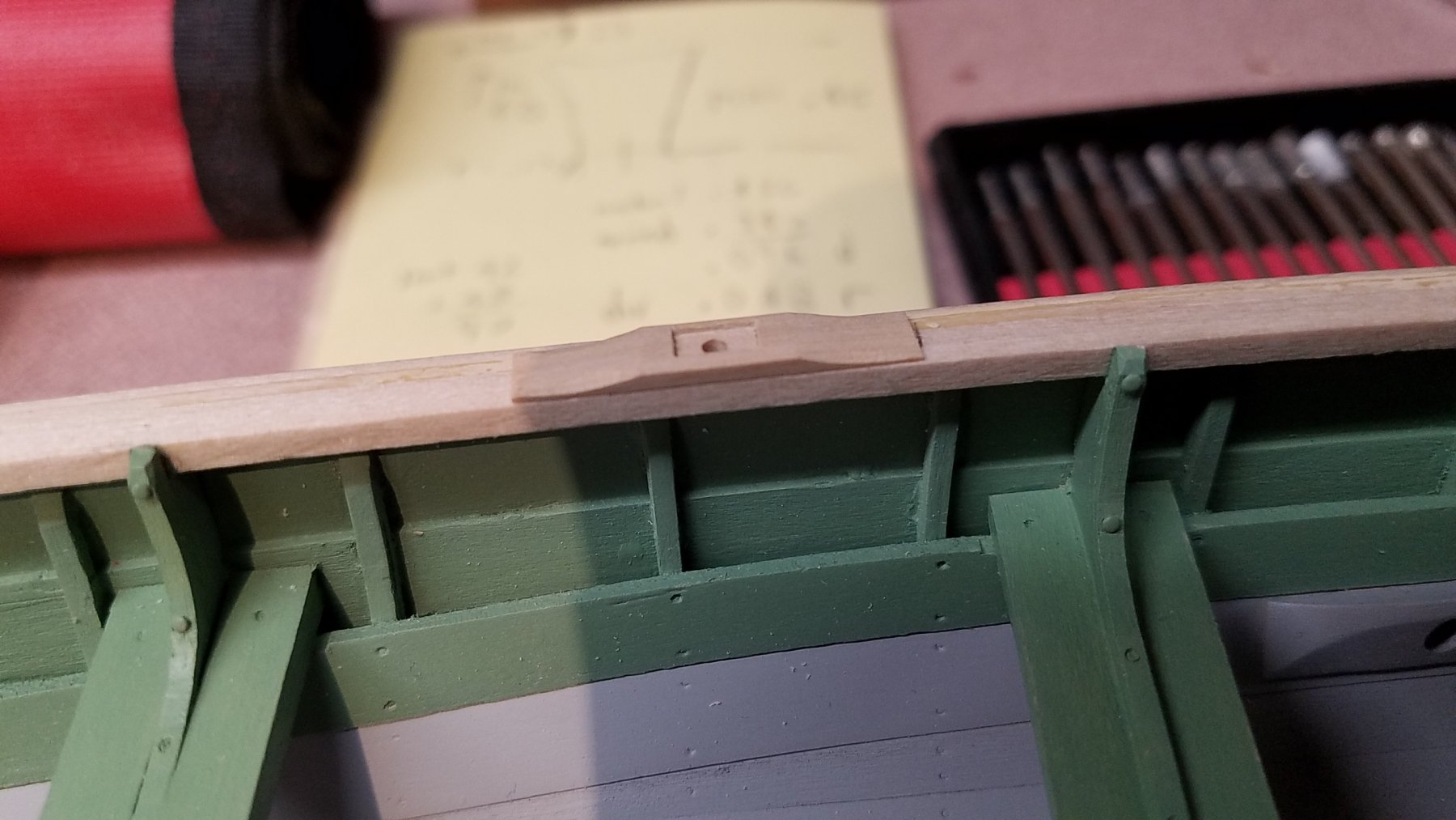
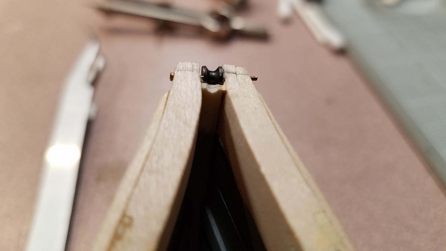
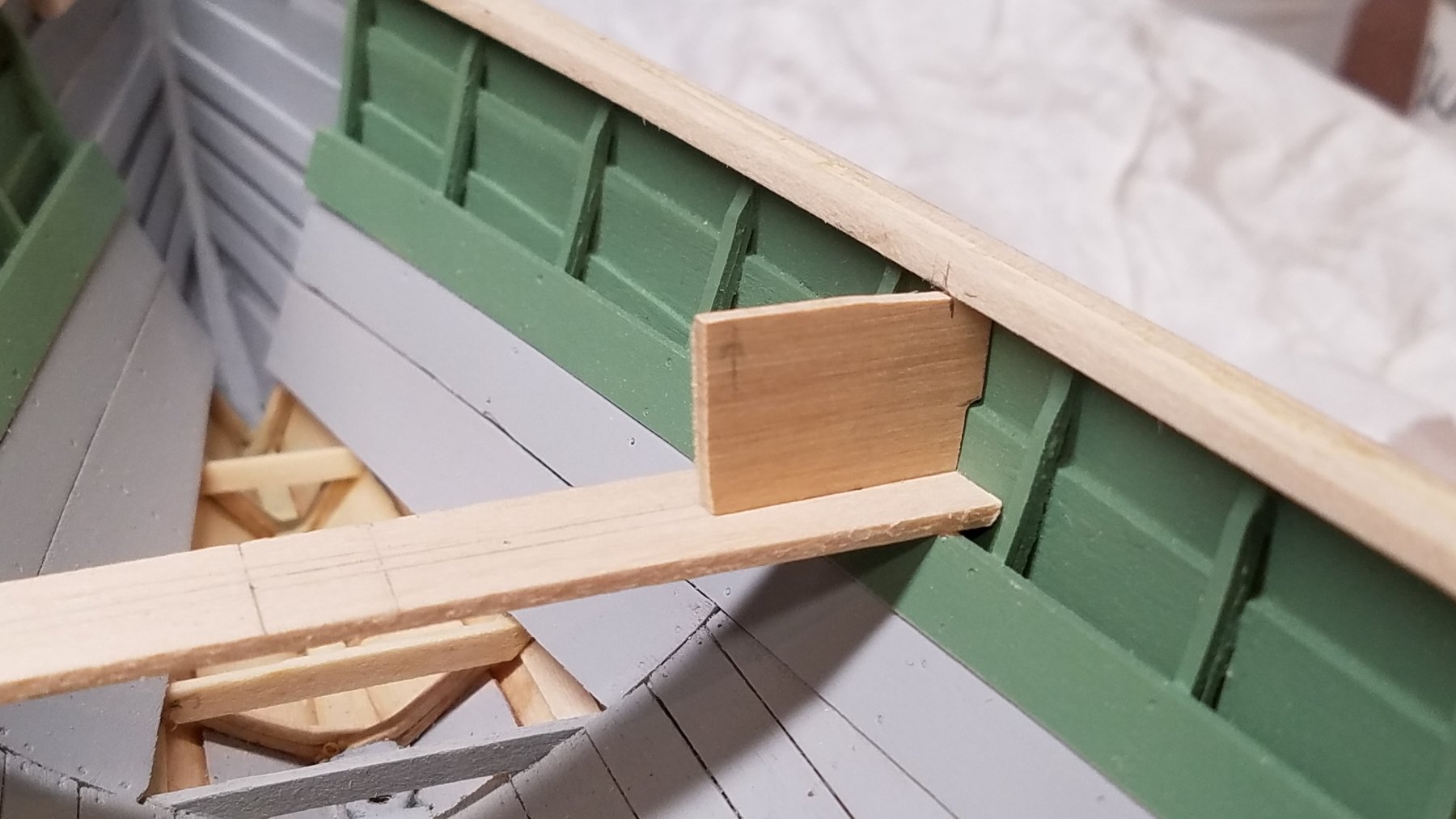
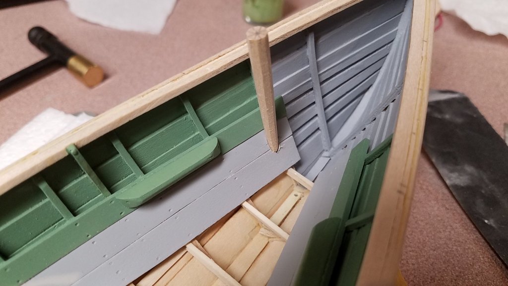
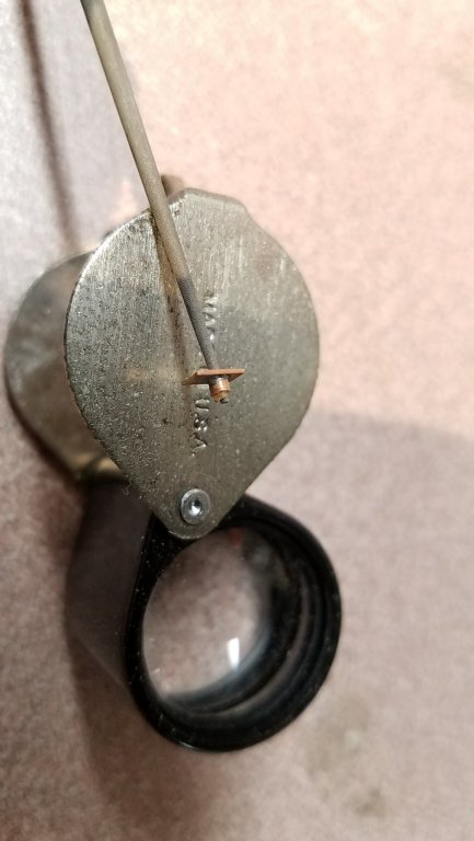
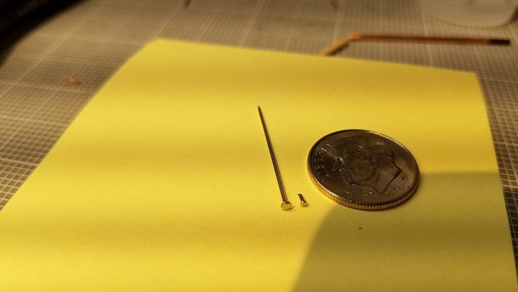
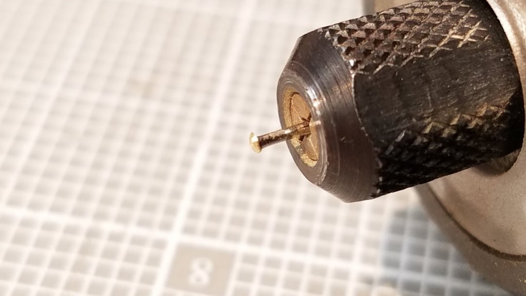
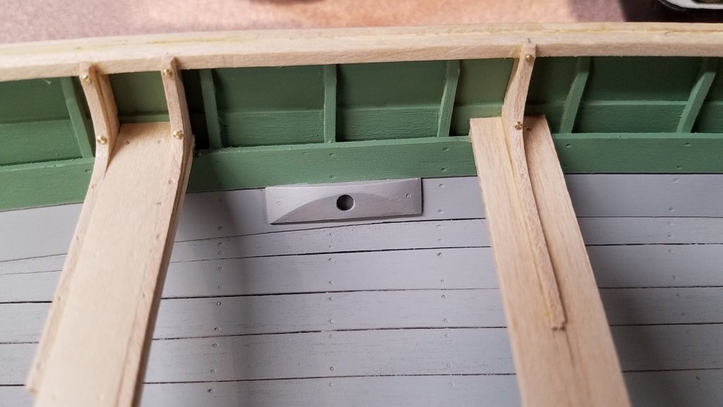
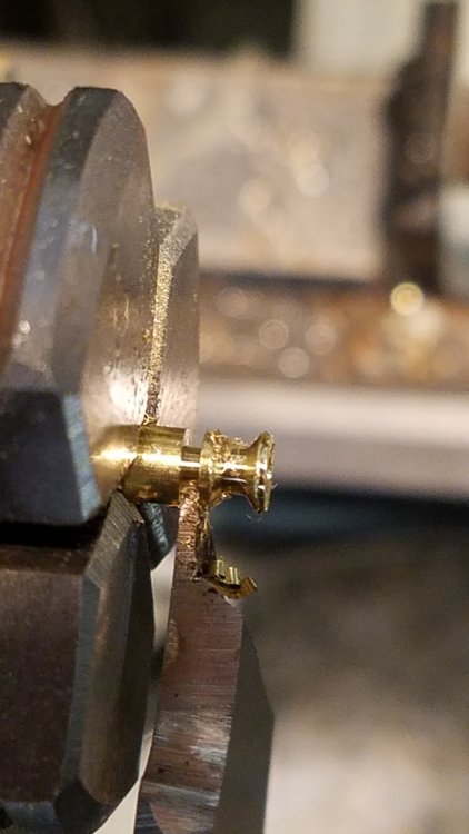
Catching Up on Small Parts The whale boat uses some larger riveted fasteners that I decided to try to replicate with brass pins. The majority of these are used on the thwart knees and all of them will be painted over. After several trials, I settled on the version shown below. One can be made in just a few minutes.... dropping one really takes up time. The pin is held in a rotary tool and the head of the pin is first flattened down to it's widest diameter. Then the diameter is ground down against sandpaper to the scale width desired. In this case, slightly smaller than the width of a hull frame member. They are cut off and push fit into a suitably drilled hole but do not to go all the way through the hull. The foot brace is made from boxwood. At this point, it's just a push fit into the stern sheets and the thwart riser so I can remove the sheets easily. The brass bow roller is blackened and set just below the top of the cheek pieces. Note, the bow chocks are not installed yet. Also, there should be a shallow groove in the stem piece just behind the roller. ...back to applying sanding sealer to the thwarts, etc. Mike


- 128 replies
-
- 5
-
-
- model shipways
- new bedford whaleboat
- (and 1 more)
-
Thank you Doug. I appreciate the comments. Time to catch up on my build log today. Mike
-
Hi Steve, The only maple that I have used so far was for the laminated bends for the hull frames and the thwart knees. So two pieces of 1/32" x 1/16" glued together after wet bending. The maple was far better than the basswood for that purpose. With that thickness, a 20 minute soak and working it a little with your fingers, it easily wraps a 3/8" diameter. It also holds an edge much better than basswood and doesn't fuzz up when wet bending. I read in the guide that holly also bends well. As you would expect, the maple does not shave/chisel as easily as the basswood. Mike
- 128 replies
-
- 1
-
-
- model shipways
- new bedford whaleboat
- (and 1 more)
-
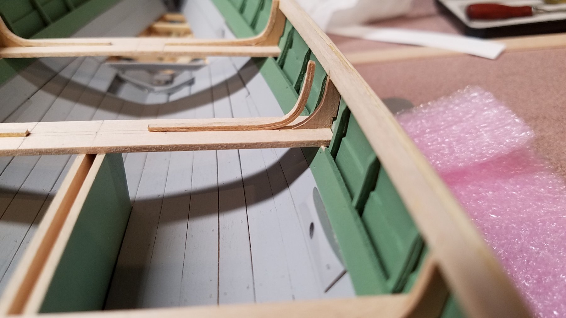
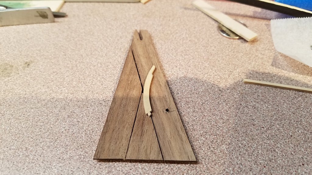
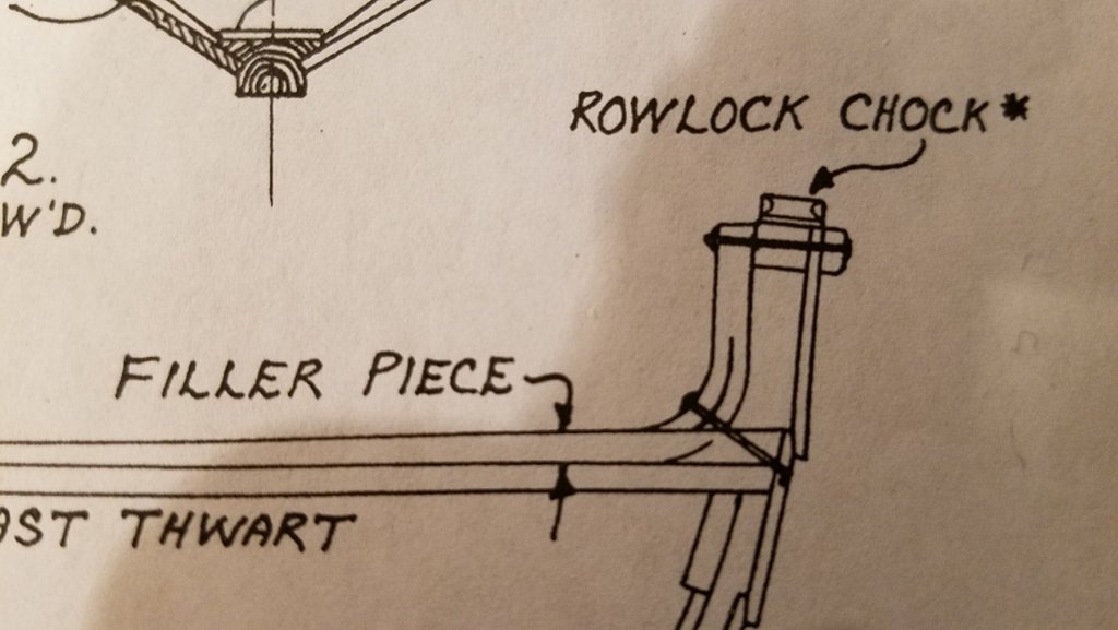
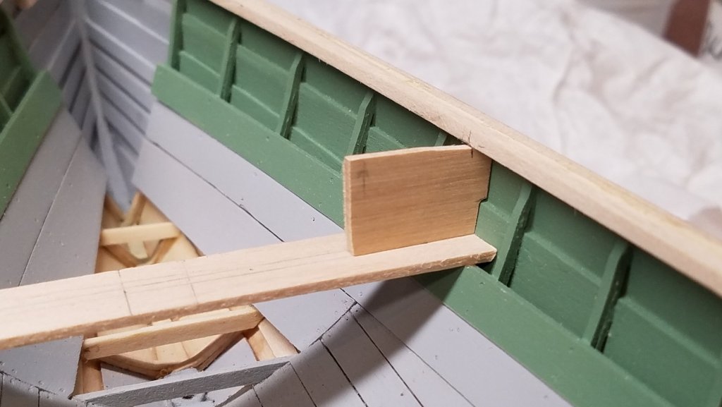
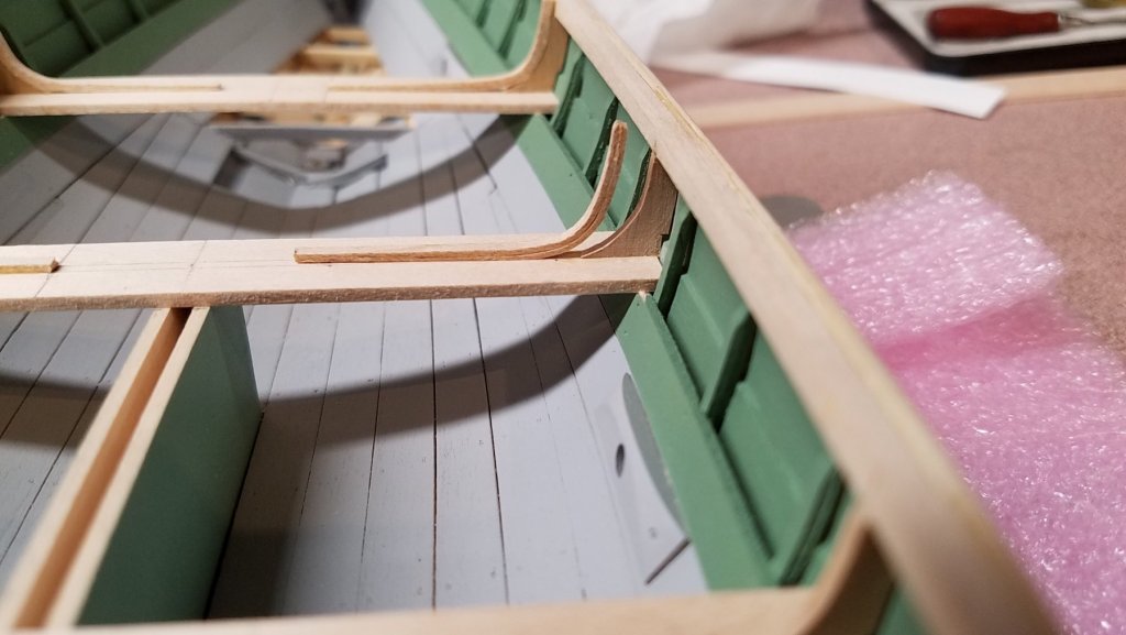
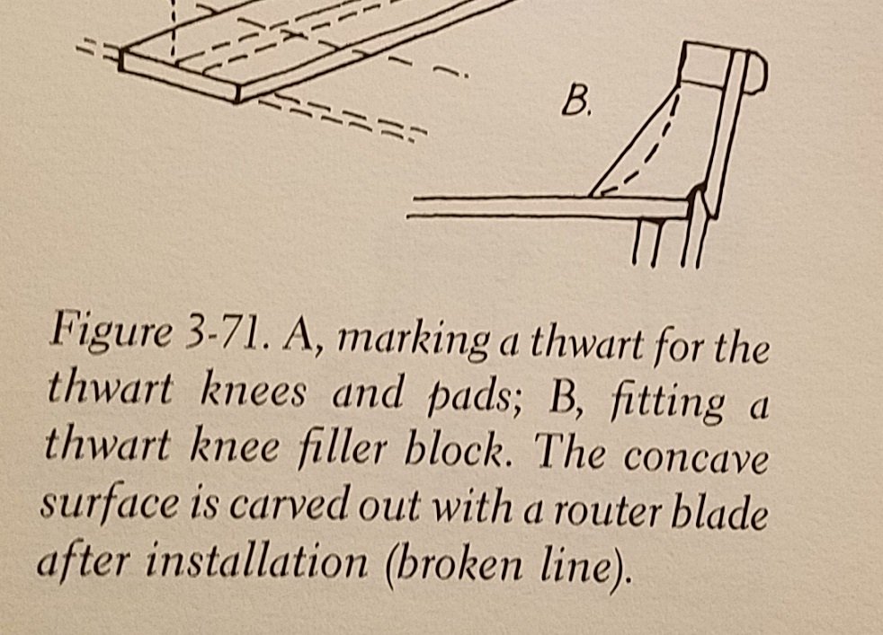
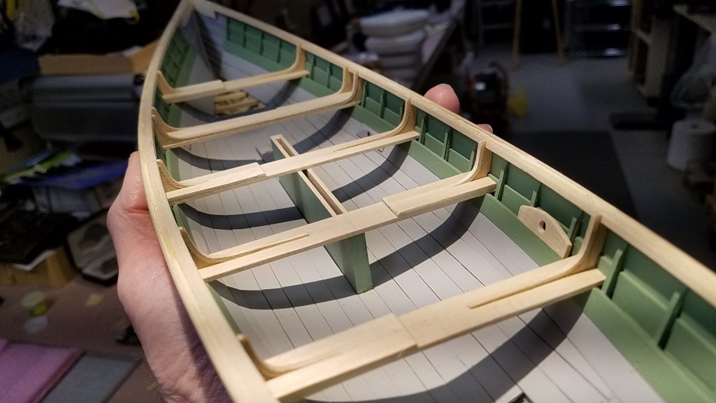
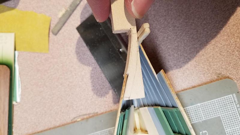
Thwart Knee Fillers The build guide and plans differ a little in the curving of the knee filler pieces. The guide shows a wider curve ending at the wales while the plans show a tighter curve blending to an almost vertical section up to the wales. I chose to mimic the plans version using some 1/16" castello boxwood with the grain running parallel to the thwart. The boxwood is much more robust than the basswood especially at the point where it meets the thwart. The maple knee strips were bent separately in a jig then glued together approximating the shape of the filler pieces. The thwart pads are straightforward although the the photos of the Delano boats show that the padded knees are not as tapered toward the center line as the un-padded knees. Comments or questions always welcomed, Mike
- 128 replies
-
- 7
-
-
- model shipways
- new bedford whaleboat
- (and 1 more)
-
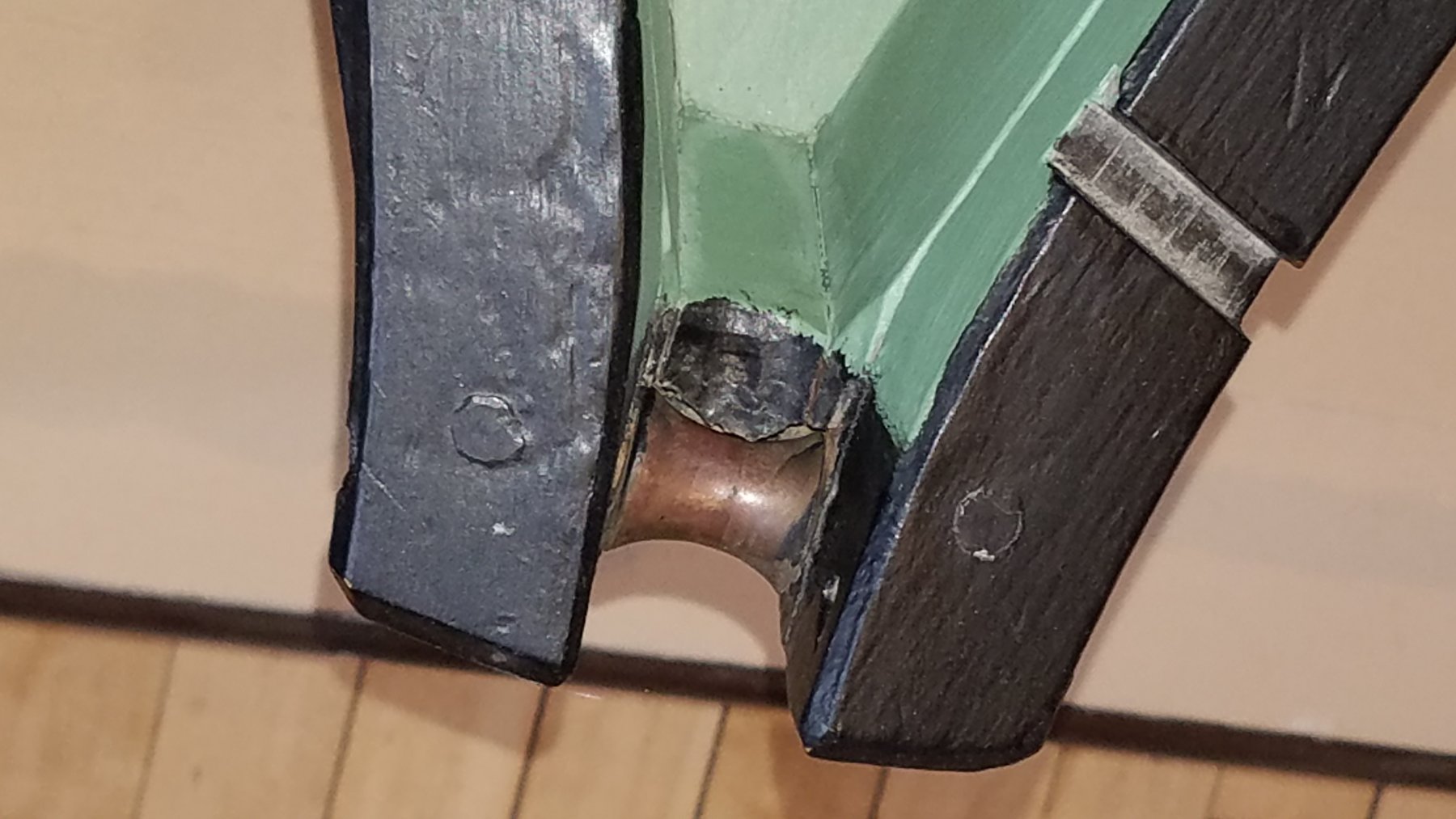
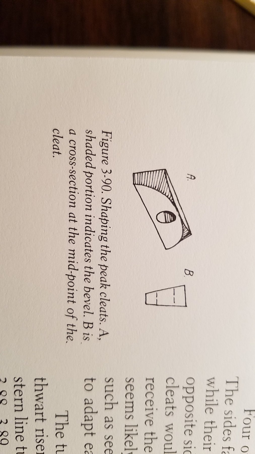
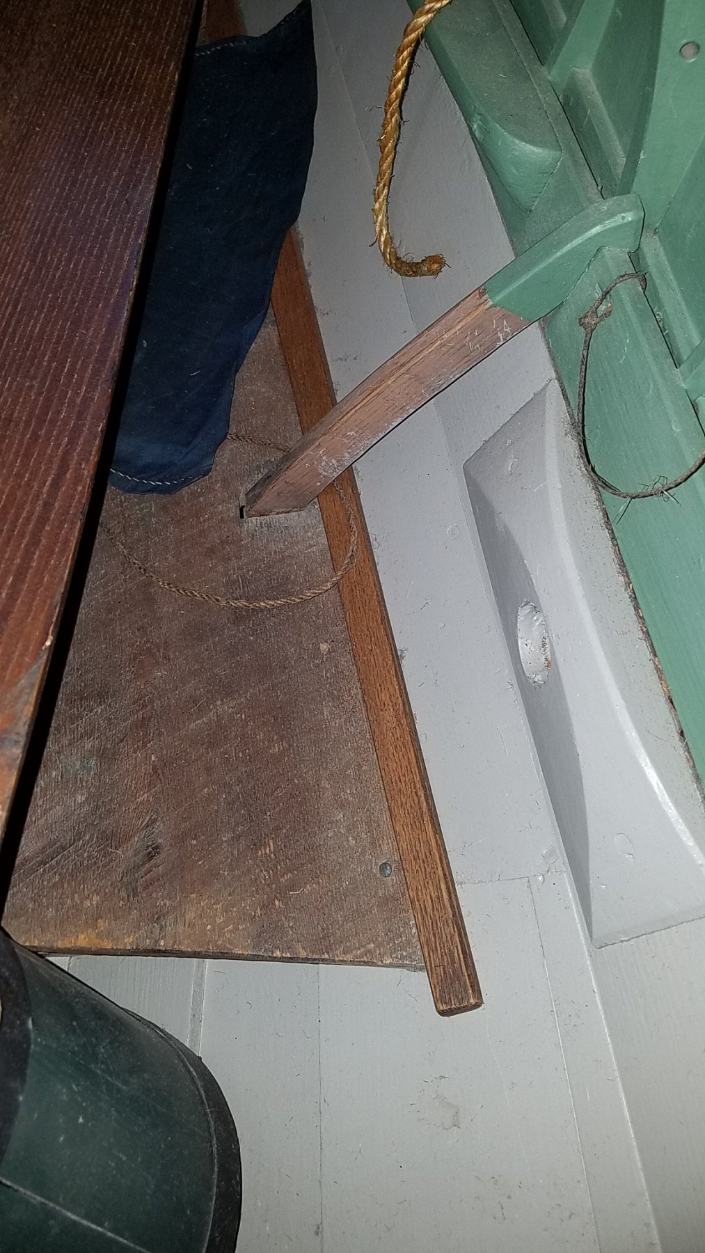
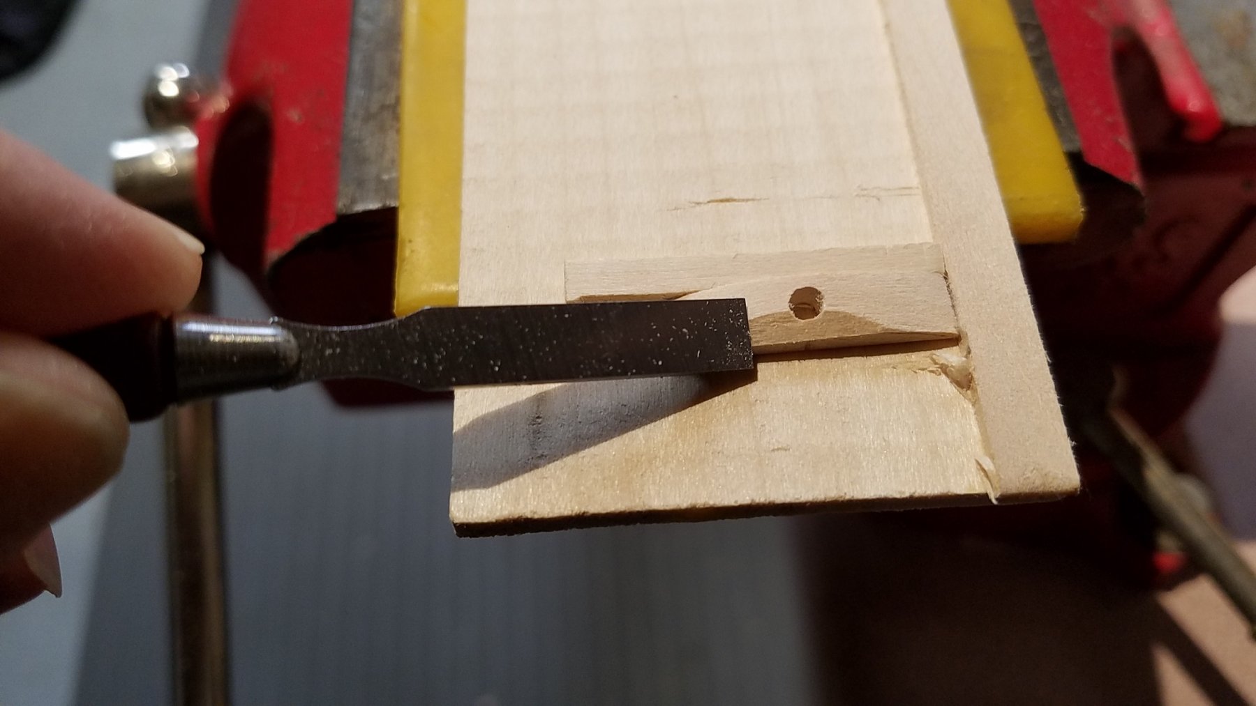
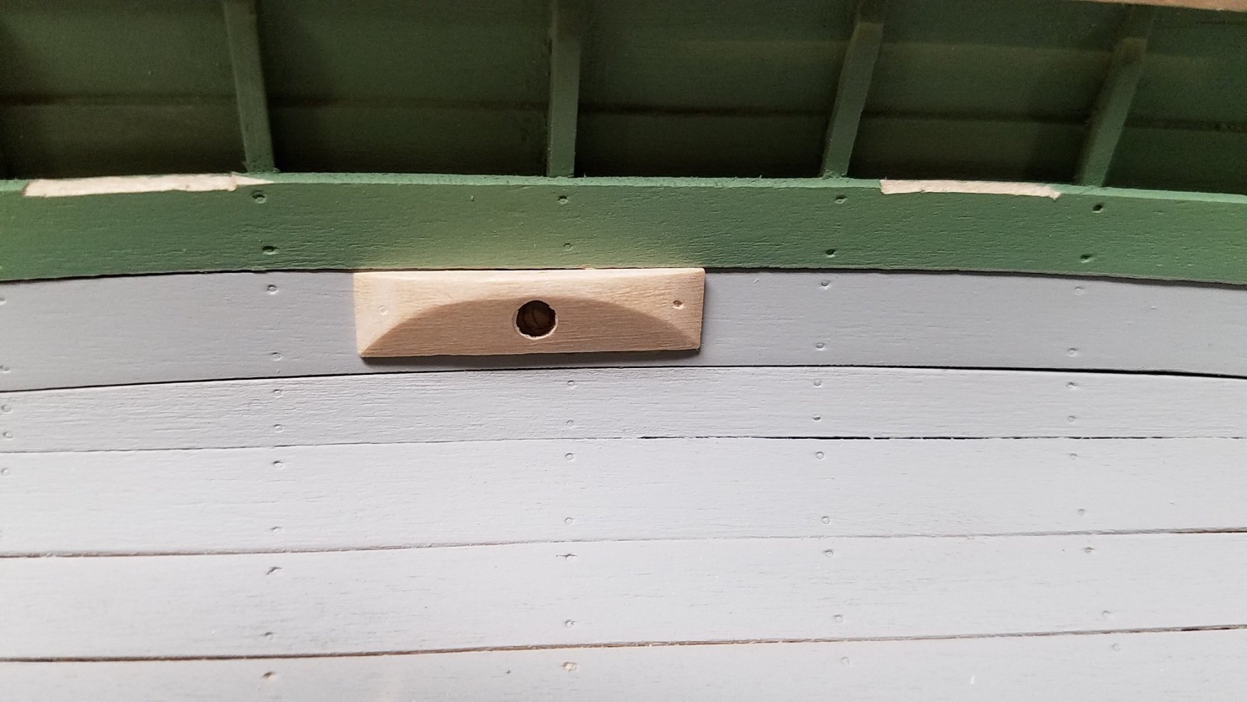
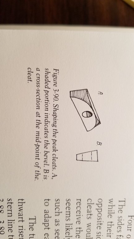
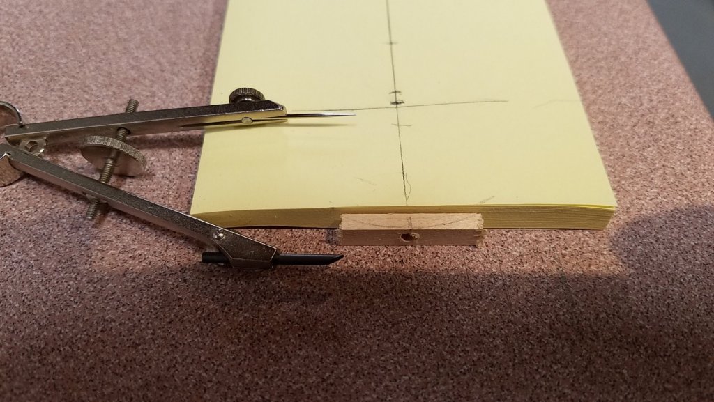
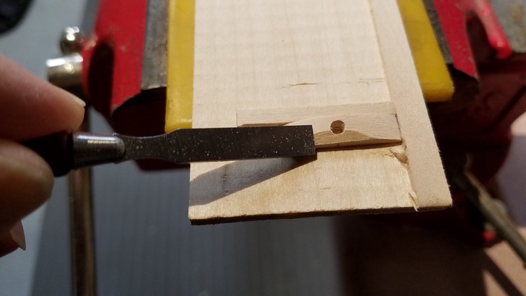
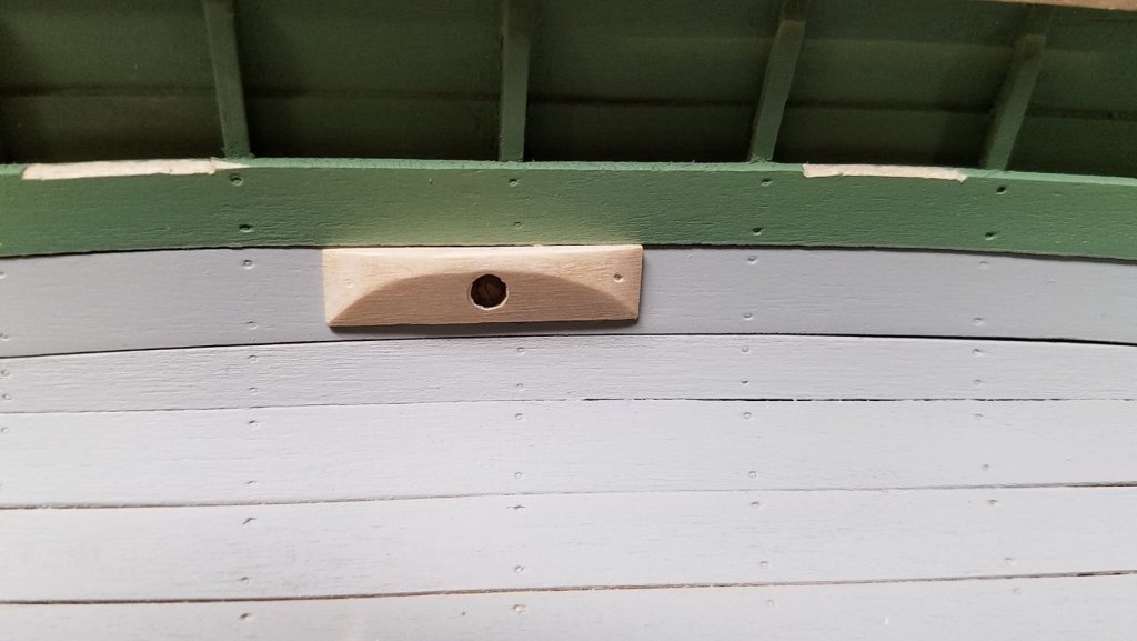
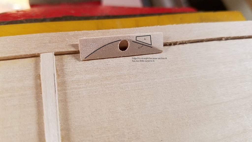
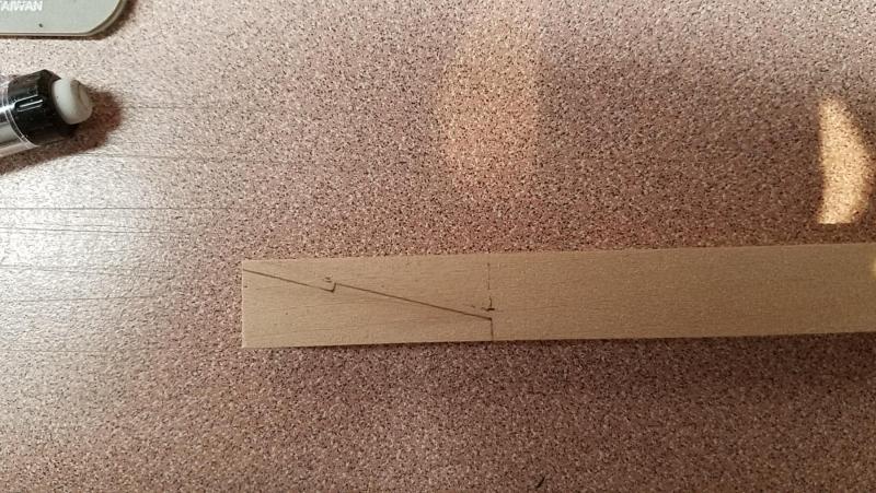
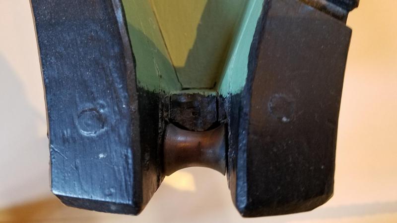
I'm a bit behind in the build log so it's catch-up day today. Per the build guide, thwart installation is next but I skipped over that to work on the peak cleats without the thwarts getting in the way. The build guide includes a sketch that represents the the shape of the cleat and of course the plans have a few different views. Sorry again: The site is still rotating my photos... Here is a photo of a cleat in the 1/2 scale boat at the museum. It helped a lot in understanding how to shape the part as simply as possible. This little piece has a nice curve on the inboard side which I'll call the "inboard curve". Once the hole is drill in the face, the shaping can be done in two steps: Creating a curve on the face and beveling an edge. Note: the bevel in this method does not match the bevel in first photo which seems in to be an error or just a just a long way to get it done. (or, more than likely, I just didn't get it ) This curve is important, if it has any flatness to it, it will project onto the inboard curve after the final bevel. Just one straight bevel is needed to go from the top of the hole to the bottom edge. Note the flat part on the right side of the inboard curve. It is due to a flat section on the face curve and is corrected with more rounding on the face curve. I tried to edit the photo in MS Paint but the font turned out too small. One done ..... Mike

- 128 replies
-
- 5
-
-
- model shipways
- new bedford whaleboat
- (and 1 more)
-
Hi Steve .... continues to look great! +1 for the rudder. Mike
- 165 replies
-
- 2
-
-
- finished
- model shipways
- (and 1 more)
-
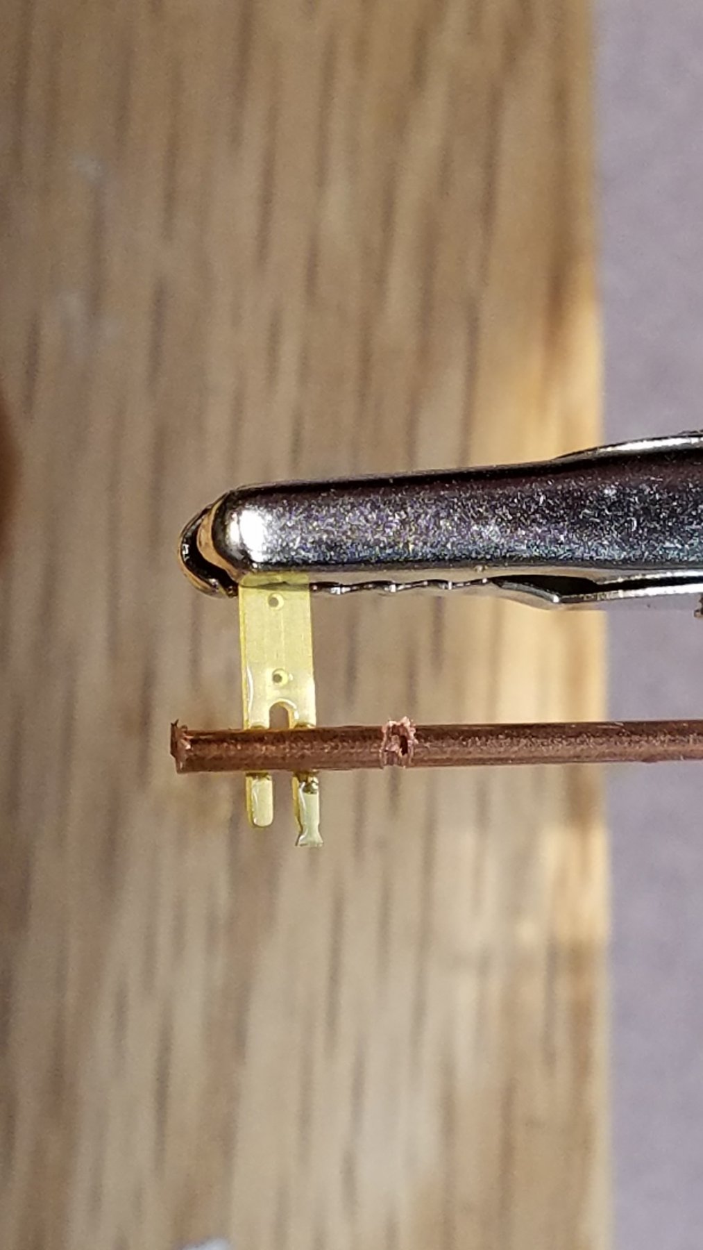
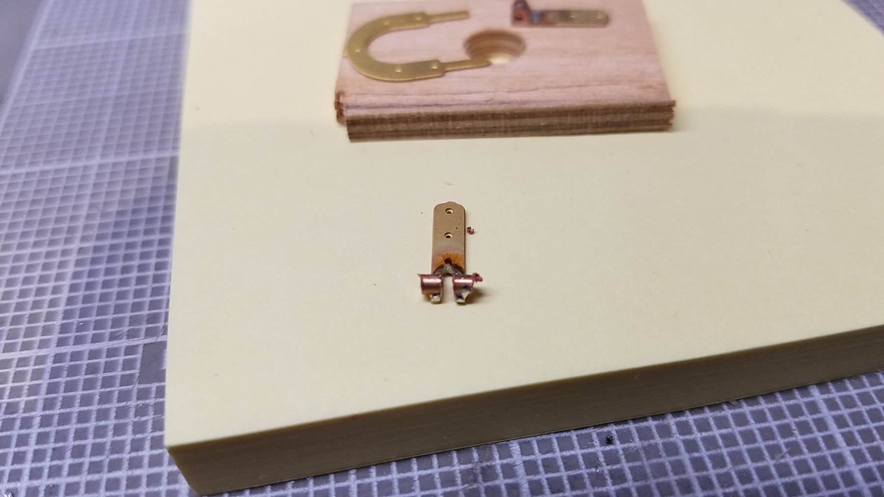
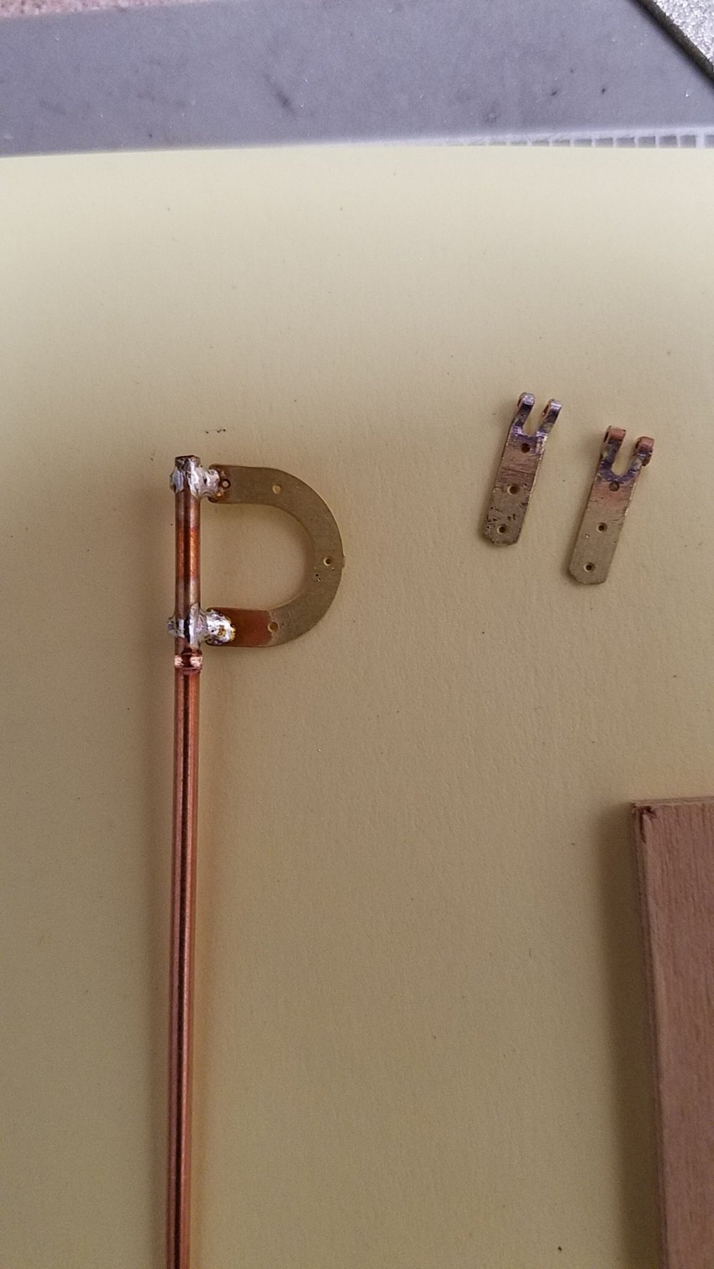
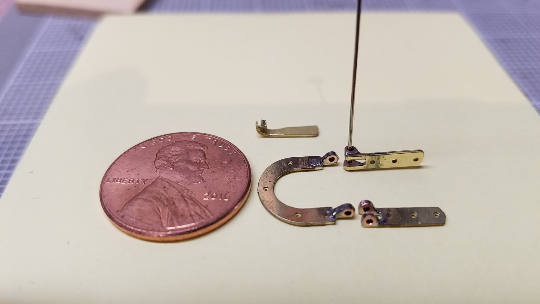
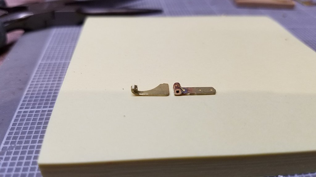
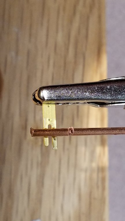
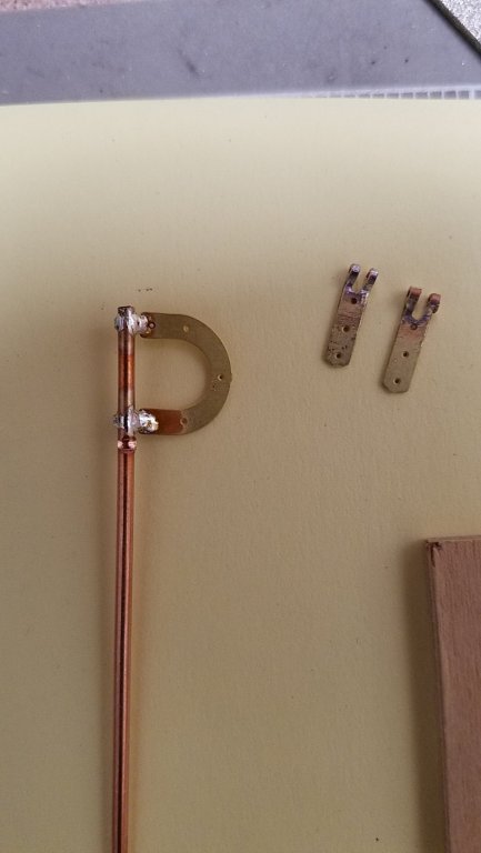
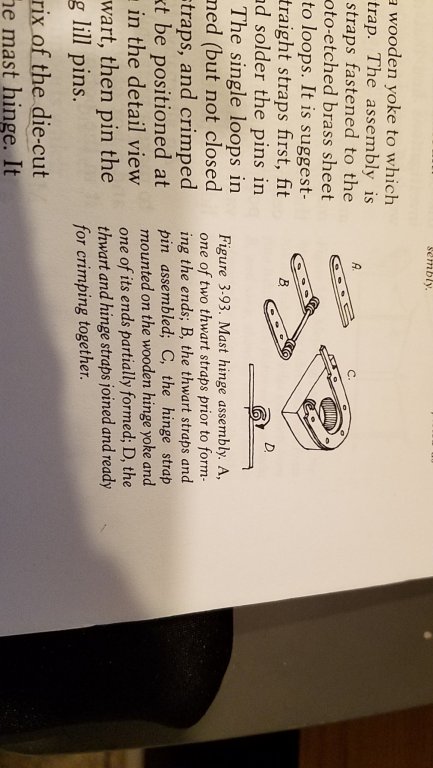
The instructions for the mast hinge assembly (photo) suggested forming the etched brass strips into a hinge by curling over the small tabs. On practice material, I just couldn't get the brass uniformly curled and the more I worked on it, the worse it looked. Possibly, the tools I have (hardware and skillware) are not right for the job. Sorry again for the rotated photo .... it seems random since the site update. Other photos are fine. I happened to have some copper tube and after a few versions of soldering the tube to the brass, the below method seems workable. I'm trying to get the axis of of the hinge all in line. The piece on the left is made from scrap and the forming was very difficult. The piece on the right is made using one piece of copper tube then sliced after soldering. Note the piece of copper tube has a partial cut in it about 3/8" in from the left. That's actually the key to the solder job. The cut prevents the heat from running up the tube and giving a cold joint. Also, just under the copper, are two small grooves ground into the brass tabs. The groove stabilizes the position of the copper. The tube gets sliced up with a rotary tool. The cutoff wheel is just thin enough to cut and finish grind the inner groove. ... using the same procedure for the horse shoe shaped part. I have some Brass Black on order. Hoping(?) it will blacken the brass, copper and solder. Note: I used electronic grade solder here and have not tried silver soldering .. would that be applicable on small parts? Mike


- 128 replies
-
- 5
-
-
- model shipways
- new bedford whaleboat
- (and 1 more)
-
Thanks Steve, the encouragement goes a long way! Mike
- 128 replies
-
- 1
-
-
- model shipways
- new bedford whaleboat
- (and 1 more)
-
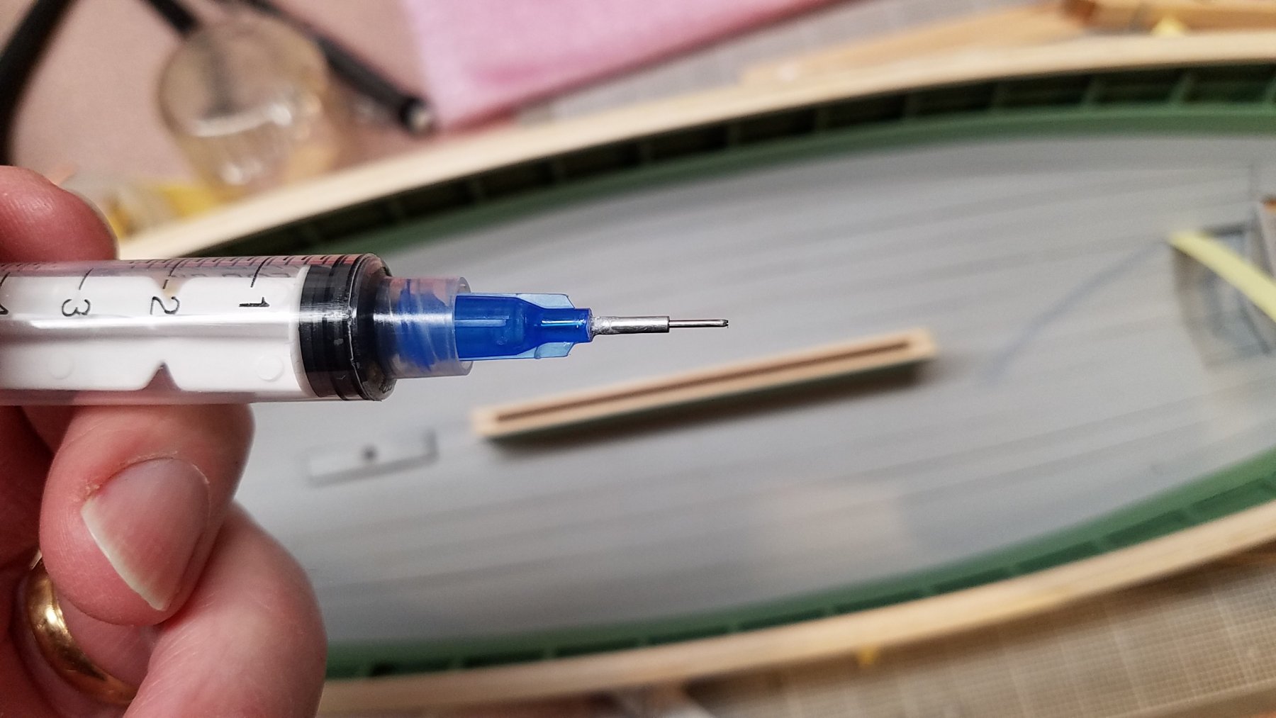
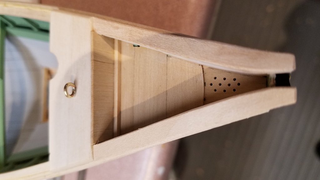
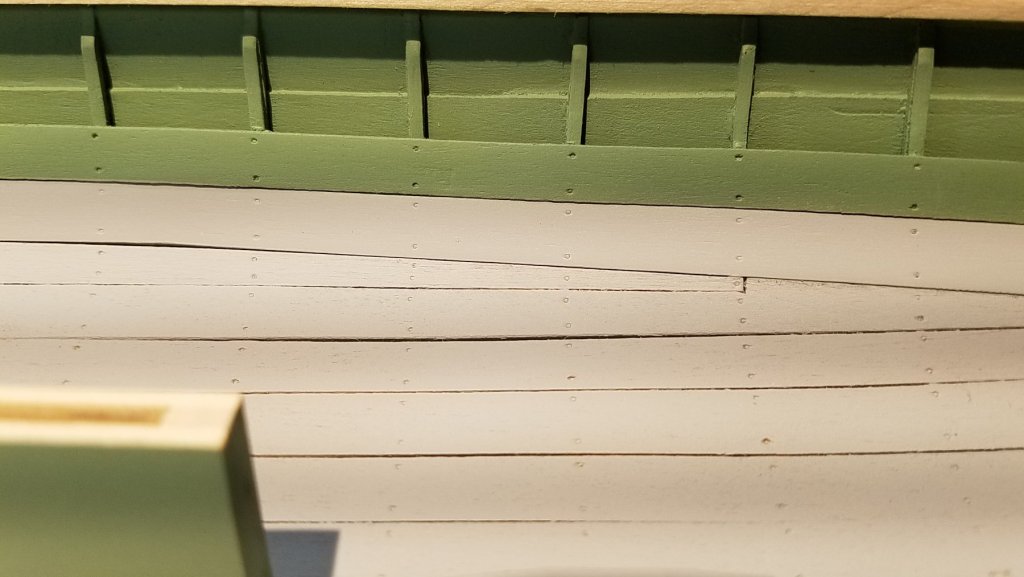
Hi JP, thank you for your comments. Actually, the Armed Virginia Sloop was one of the models I was considering this time. I opted for the whale boat mostly because my proximity to New Bedford and Mystic. Regarding varnishing, I tested the Krylon matte spray as well as assorted ratios of Vallejo matte to thinner. I feel that airbrushing the varnish is much more controllable so the inner hull is now varnished with airbrushed Vallejo. With thin coats, the finish is flat which was my preference. I've never used treenails, nails, rivets etc. before but wanted to try it this time as long as I could keep things to scale as much as possible. This site had a lot of great tips for which I have much appreciation. Here is the scheme (so far) and some thoughts about what I'll try: Outside Hull: - generally paint smooth where plugged over screws attach the planks to the timbers. These are all but imperceptible on the subject whale boat at the New Bedford Museum. Ceiling Planks: - try to replicate ~1/4" plank-to-timber hammered nails. (attachments) Other: - try to replicate any hardware over 1/4" i.e. through bolts, peened over rivets, etc. Likely, these will be reworked miniature brass nails. Here is the tool used for the simulated nails in the ceiling planks. The blue hypo needle is sharpened on the outside using a #800 sandstone. Time to emboss ~700nail heads -- 4 hours. Time to figure out which way do it... 3 weeks. After some use, the needle tends to bend. A small sleeve of aluminum tube slipped over the needle solves the problem. Mike


- 128 replies
-
- 4
-
-
- model shipways
- new bedford whaleboat
- (and 1 more)
-
Last week I talked to the resident go-to person for this kind of question at the New Bedford Whaling Museum. Generally, the half scale Lagoda itself was gilded a bit more than the average whaling vessel. Also, the white circles may have meant nothing other than what was desired by the painters at the time. Mike
- 1 reply
-
- 3
-
-
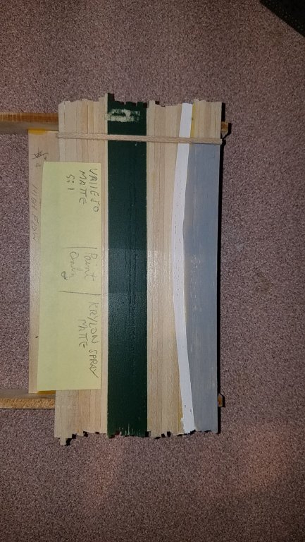
Hi Pat & Steve, thank you for your comments. Not much to show today. I just finished gluing on the inwale & gunwale boards.... needing to rob more of my wife's clothespins. I've been testing different varnishes i.e. the Krylon matte suggested in the build guide vs. trying to get something to shoot with the airbrush. I like the flat look it has now with just the paint so I don't want anything more than a matte shine. Vallejo has a matte acrylic varnish that I'm testing today. This shot is using a flash: Left - Vallejo matte with one dust coat using 5:1 varnish to thinner. I have to add more to get a protective coat. Center - Just paint over sanding sealer Right - Krylon Spray Matte. I can tell it will be hard to control the volume on the inner hull. Woops again.. the site is rotating the attachment. Anybody know how to get around this? Mike
-
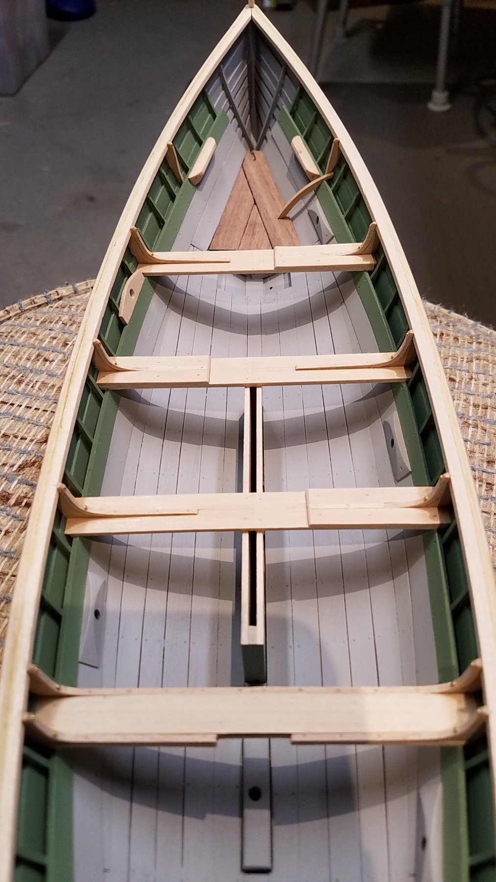
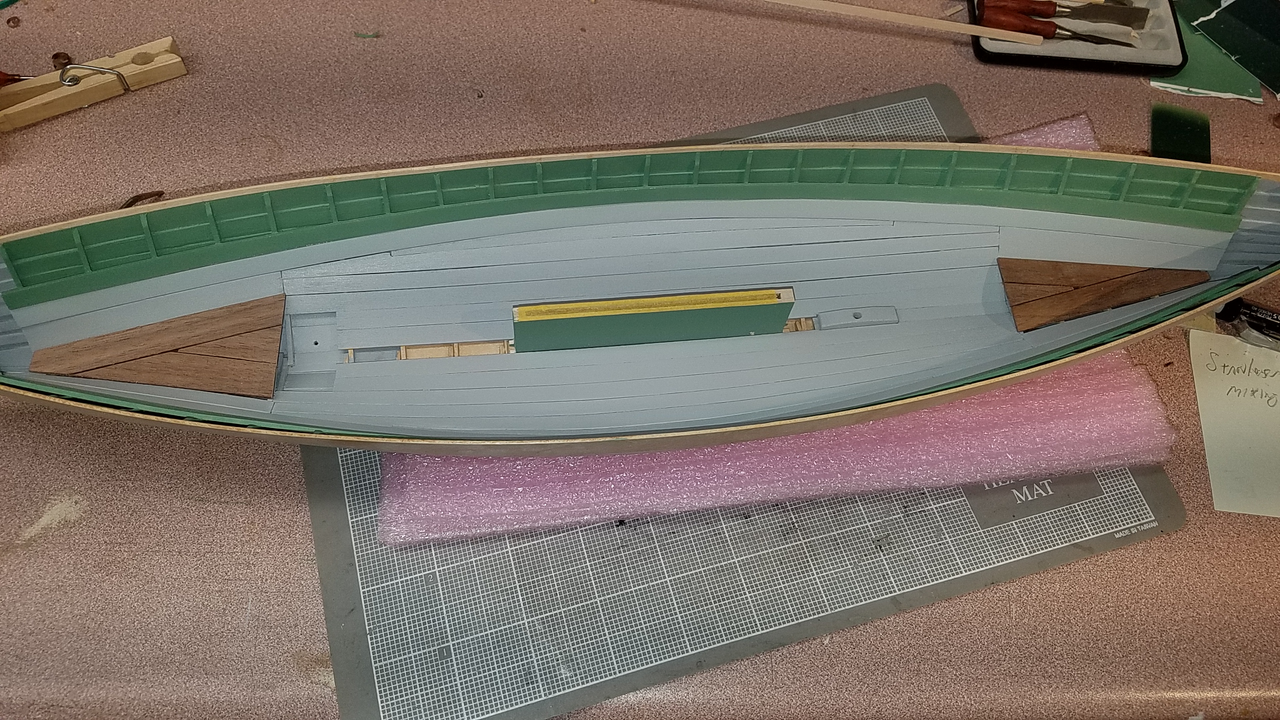
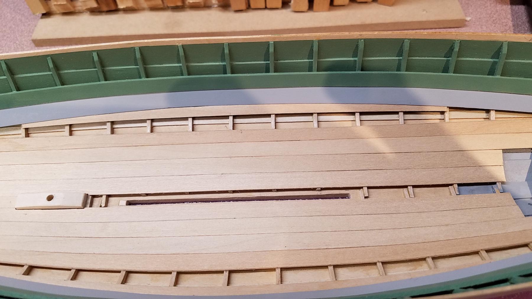
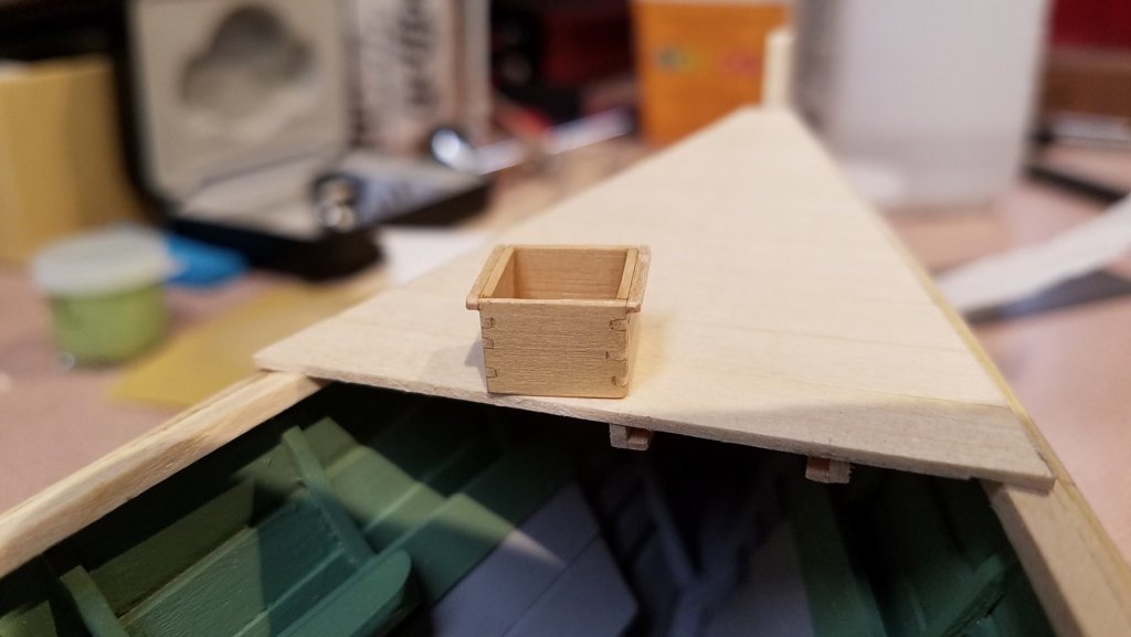
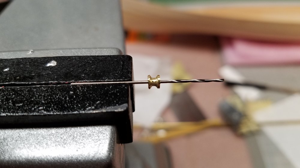
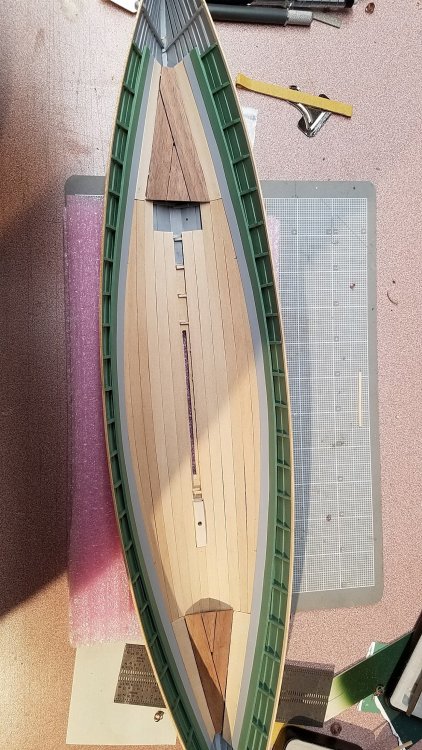
Once a year, my wife suggest I get rid of the lathe. Finally I get to tell her I produced a critical part for my whaleboat project. As mentioned in an earlier post, the kit included a wooden pulley wheel while the full scale part is made from bronze. So, after one broken drill bit and two tries, this little wheel should be ok. The ceiling planks are attached. The stem and stern sheets as well as the centerboard are made from 1/16" walnut and left in a roughened state as suggested in the build guide. Sorry, the photo above should be turned horizontally... the site seems to want it vertical. This is the up to date status of the build with ceiling planks airbrushed with 3 coats of grey. The centerboard case in not glued in yet. Mike

- 128 replies
-
- 5
-
-
- model shipways
- new bedford whaleboat
- (and 1 more)
-
Hi Steve... I'm beat. Time to take a break from my project and take a look at some else's... in this case yours! I won't ask any question as I haven't read all the posts yet. Nevertheless, I particularly like the "crispness" of your model and it takes lots of time to get it that way. So keep up the good work. Mike
- 165 replies
-
- 1
-
-
- finished
- model shipways
- (and 1 more)
-
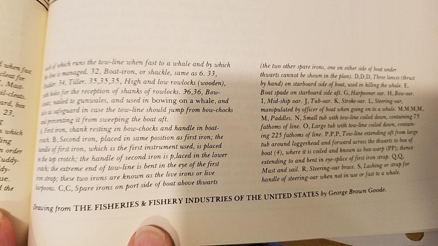
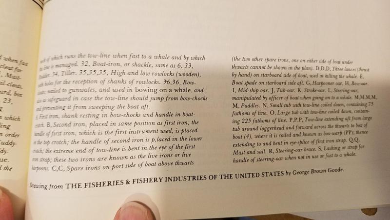
Hi Steve, the last shot has a reference at the bottom. "The Fisheries and Fishery Industries of the United States" by George Brown Goode. Mike
- 128 replies
-
- 1
-
-
- model shipways
- new bedford whaleboat
- (and 1 more)
-
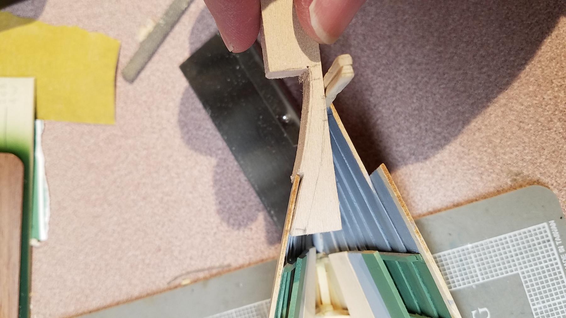
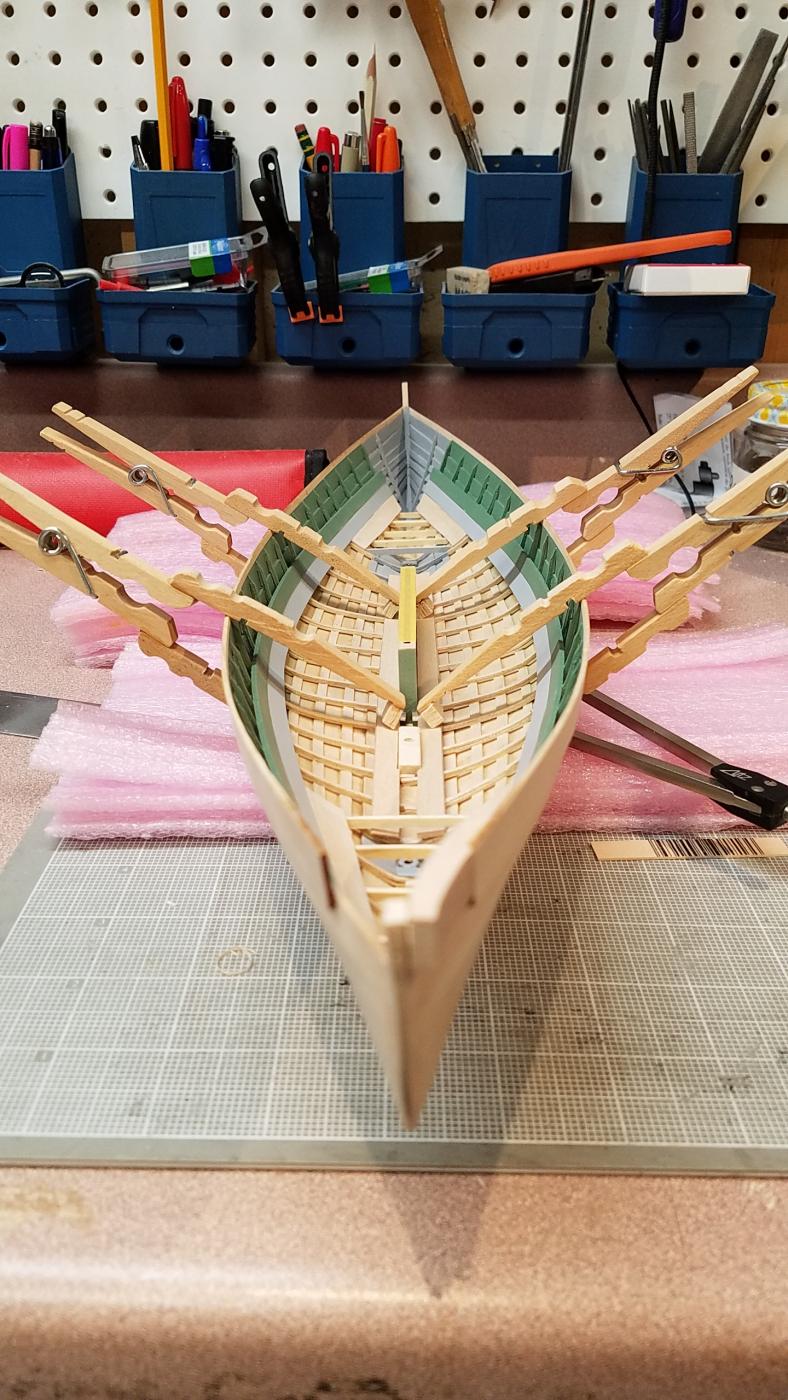
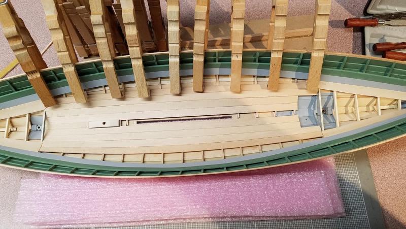
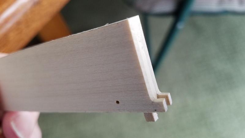
The model doesn't ship with 1/32" basswood for the ceiling plank. Not having any of that yet I worked on the two cheek pieces next. BTW, my guide has a typo calling for 1/4" x 3/8" x 1 1/2" stock for the cheeks. Actually, it should read 1/2" x 3/8" x 1 1/2". These pieces were a little tricky in that the vertical plane of the cheek that is attached to the stem needs a very specific relative alignment to the plane that attaches to the gunwale strake by way of the rabbet. That is, if the forward/aft cut of the gunwale rabbet is too shallow or deep, the forward part of the cheek will pull away from or push on the stem. Also, if the vertical plane of the rabbet is not correct, the forward part of the cheek will twist into or away from the stem. After a couple of practice tries with balsa, I found it was much easier to work the cheek pieces while they remained attached to the basswood block. Only one cheek is attached now. The kit supplied a wooden piece for the roller but I’d prefer brass. The ceiling planks were added without the centerboard in place just so my knuckles could fit. Also, I intend to airbrush them and think it will be easier with a more open area. The long reach clamps come in handy for these planks. They have (desirably) less force than a typical clothespin. The tips are made from balsa and are much less likely to dent the wood especially when wet. This is how she sits today. ... a couple more ceiling planks then onto the inwales and gunwales... Mike


- 128 replies
-
- 4
-
-
- model shipways
- new bedford whaleboat
- (and 1 more)
-
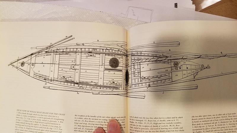
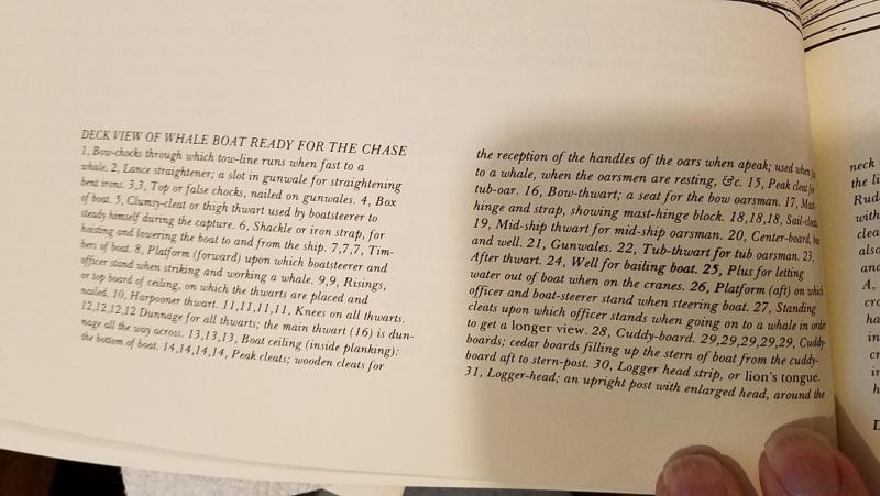
Hi David, thank you. Yes, that's a dilemma for me, at least for a little while. I just bought the (very useful) Willets Ansel book... "THE WHALEBOAT" which has an illustration called "Deck View of Whale Boat Ready for the Chase" which caught my eye. So, I'm thinking about that but haven't locked in yet. There is so much gear loaded in the boat a lot of the model detail can get buried.
- 128 replies
-
- 1
-
-
- model shipways
- new bedford whaleboat
- (and 1 more)
-
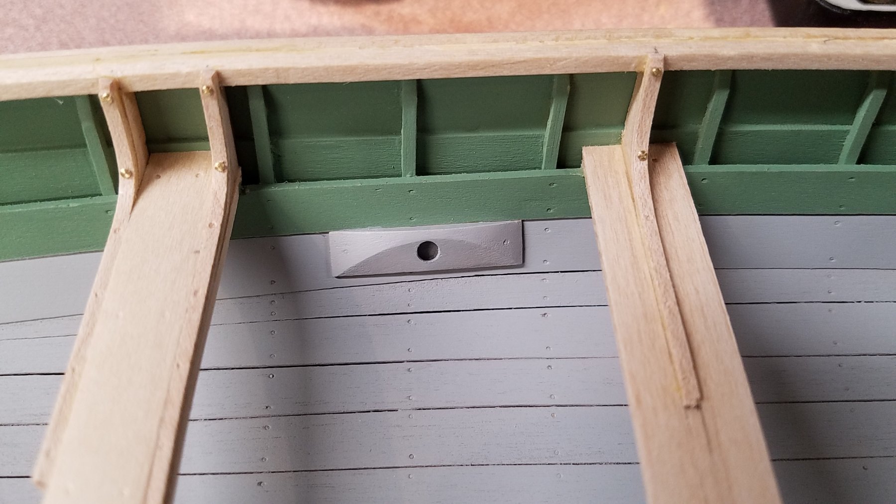
Manual Errata Note: (page 76) "Both ends of the ceiling ........ These should be cut and finished from a sheet of 1/32" veneer;..." On the kit inventory parts list (mine is form WPPL2033), the veneer thickness is corrected to 1/16". Of course, I read that correction one day too late! At least they came out without wrecking anything. (edit here) So, 30 minutes later.... I see the 1st ceiling plank (laser cut) that goes under the the thwart riser is 3/64". A 1/16" ceiling piece under that will look noticeably too thick and the section view on plans imply the same thickness as the laser cut ceiling plank. I'm going to use 3/64" leftover material from the laser cut sheet. One other potential pitfall is in regards to the lower ends of the centerboard. They should look like the photo below. It's described and called "towing" on page 77 and is included in the drawings but may not be immediately clear until page 92 of the manual. Mike
- 128 replies
-
- 3
-
-
- model shipways
- new bedford whaleboat
- (and 1 more)