MORE HANDBOOKS ARE ON THEIR WAY! We will let you know when they get here.
×

Mike_In_RI
-
Posts
276 -
Joined
-
Last visited
Content Type
Profiles
Forums
Gallery
Events
Everything posted by Mike_In_RI
-
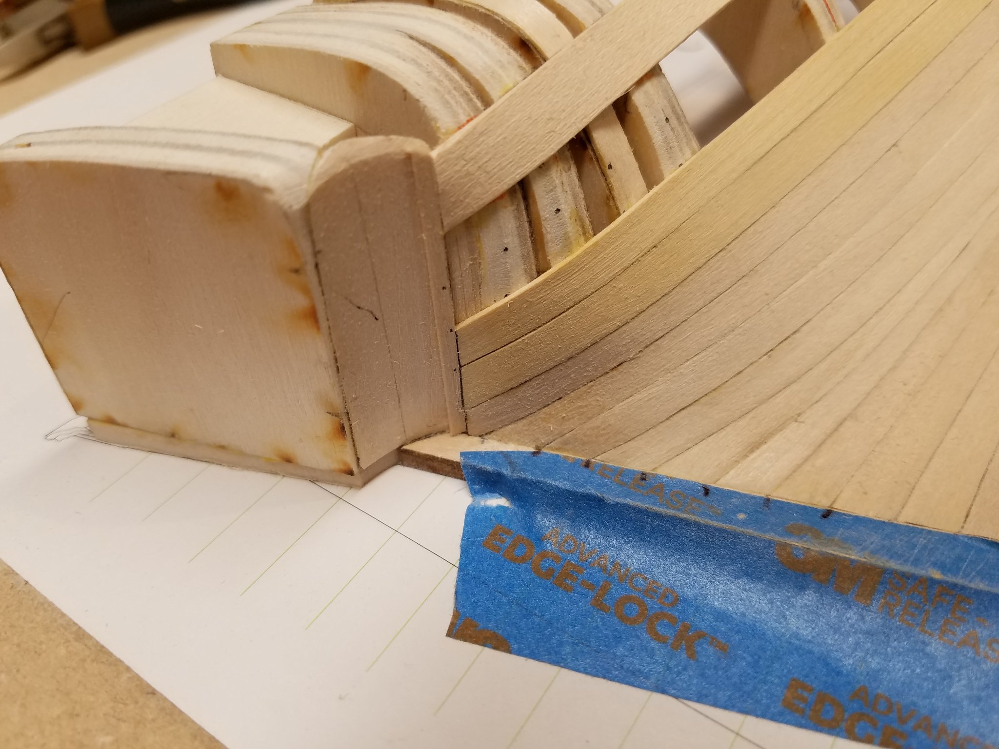
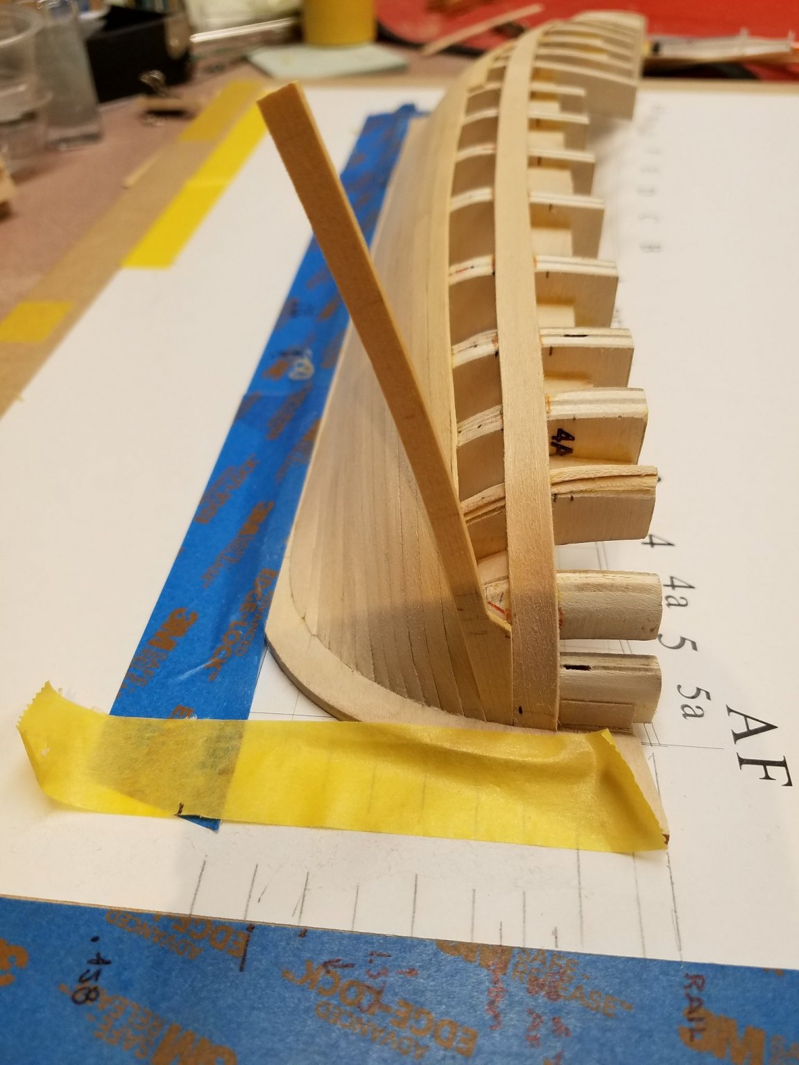
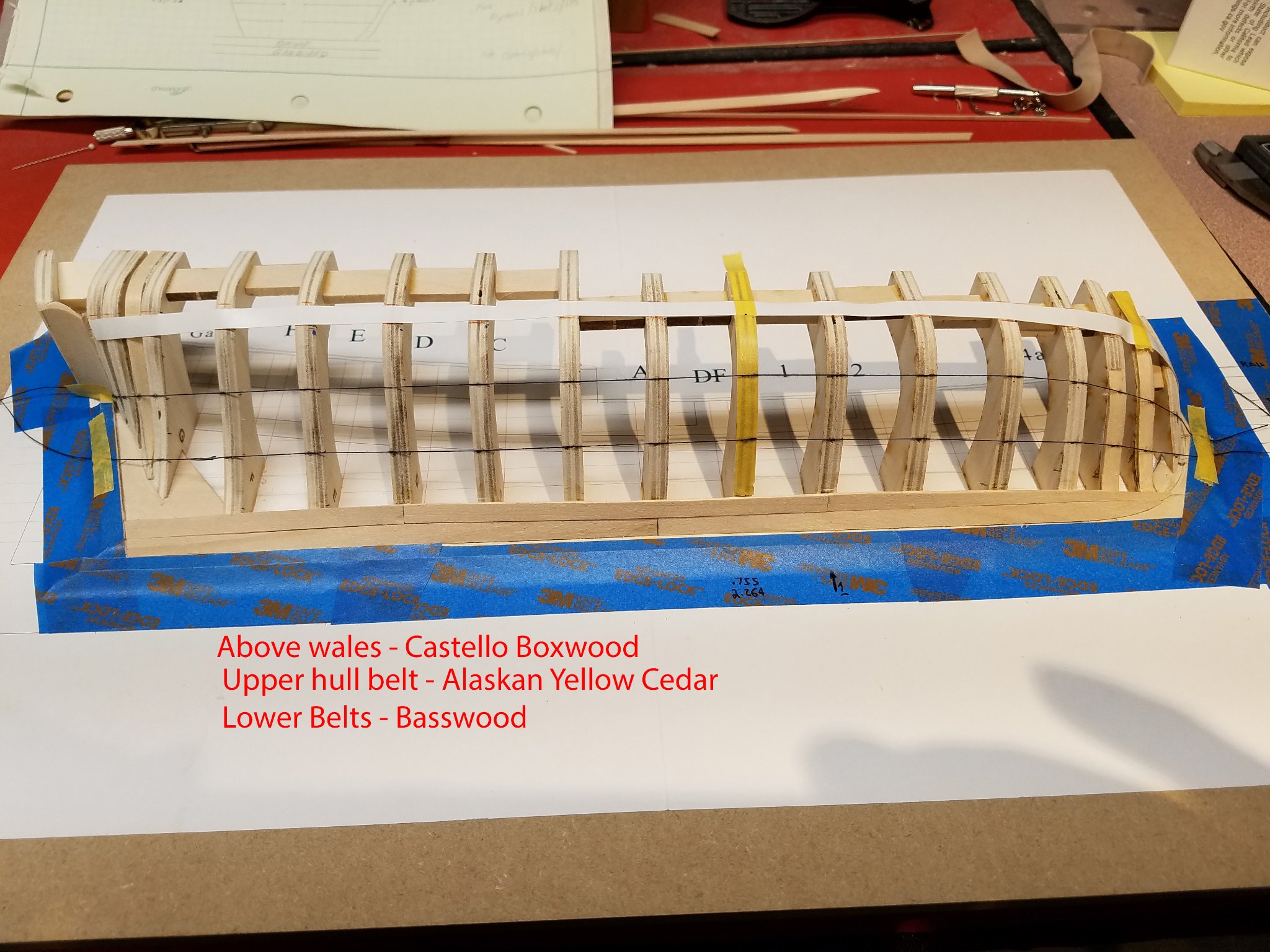
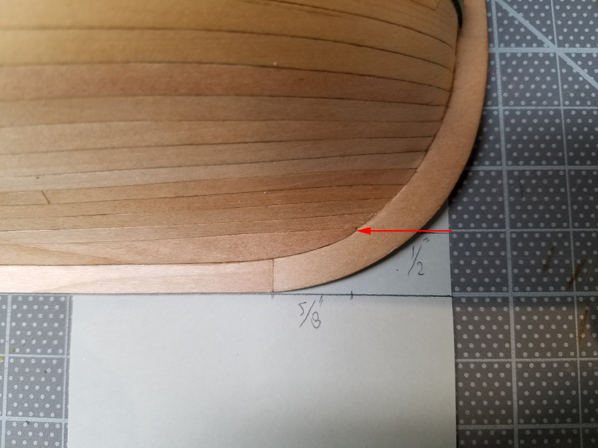
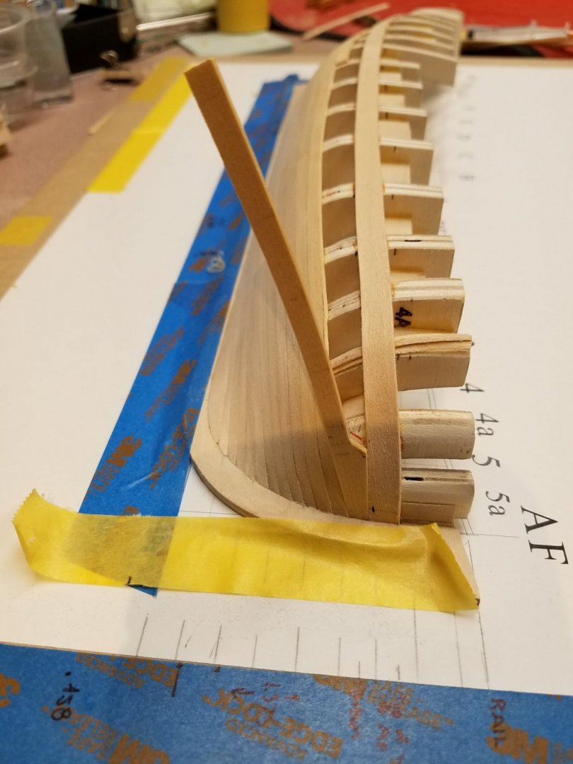
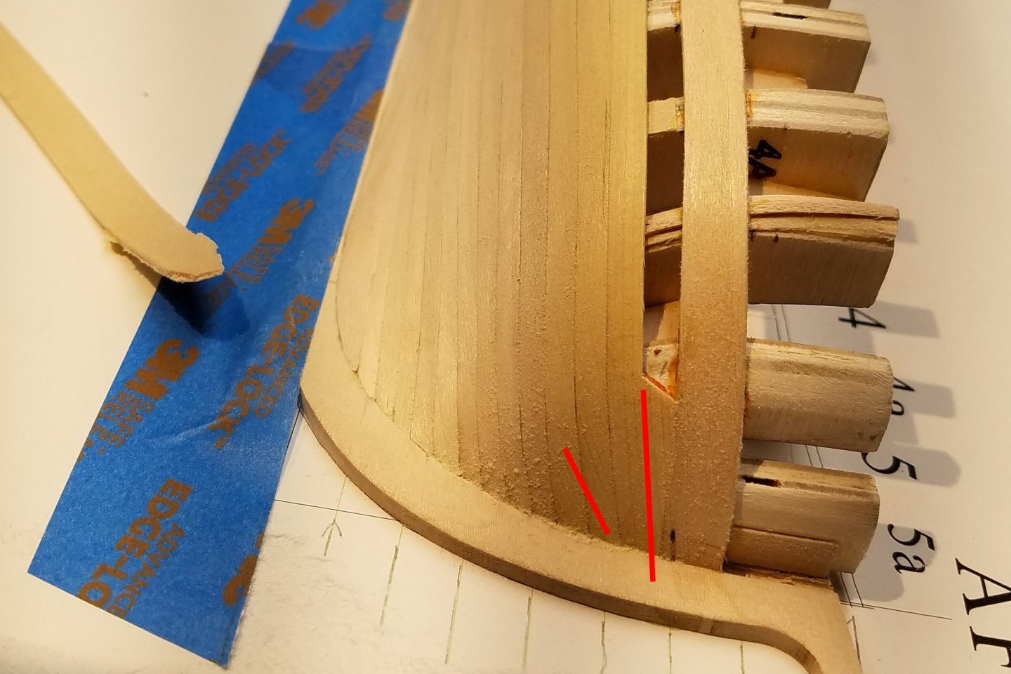
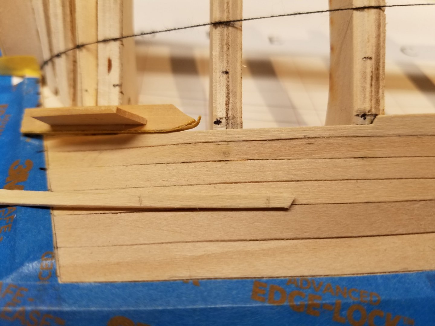
 .. 1-27-01 The stern planking went smoothly and the bending was not severe as Toni pointed out. The upper hull belt is planked with AYC. My 1st attempt at the the stem drop plank used the tape/markup/cut out method which produces a steep curve over a short length. Is seems the AYC looses it's strength when bending at such an angle to the grain. The shot of the plank on the left snapped at the stem while test fitting. I switched to the lateral bend method for this plank. The drop plank had to fit into 3 surfaces at one time at the stem so I glued that end in first and tried in-situ plank bending. It worked OK but I needed to add some water to the plank to help the bending. If zoomed in enough, one can see the resulting angle in the two AYC planks. Mike


-
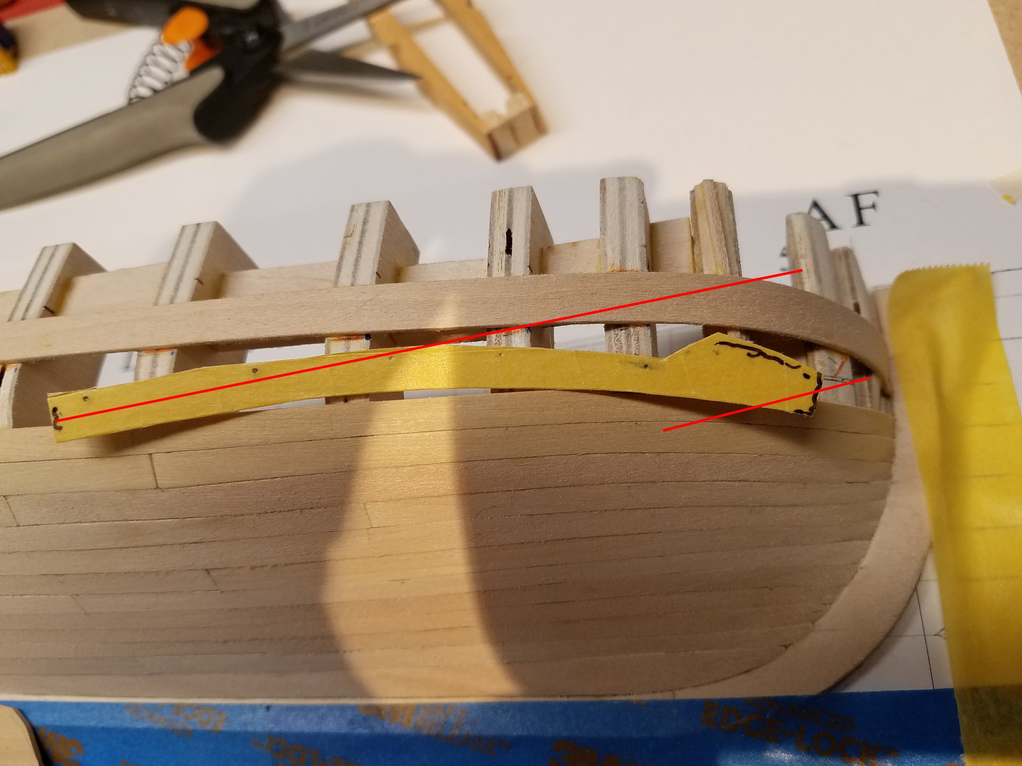
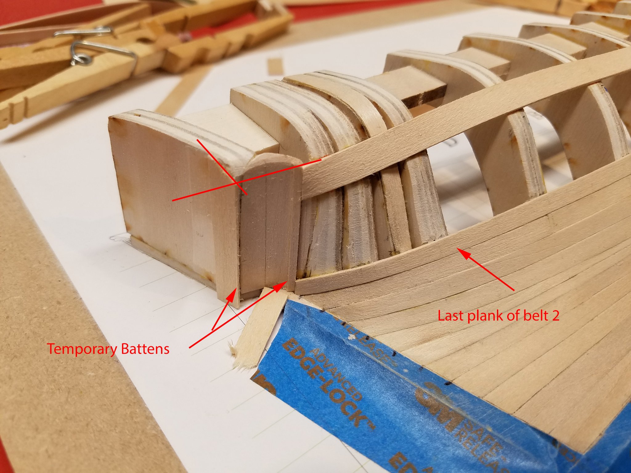
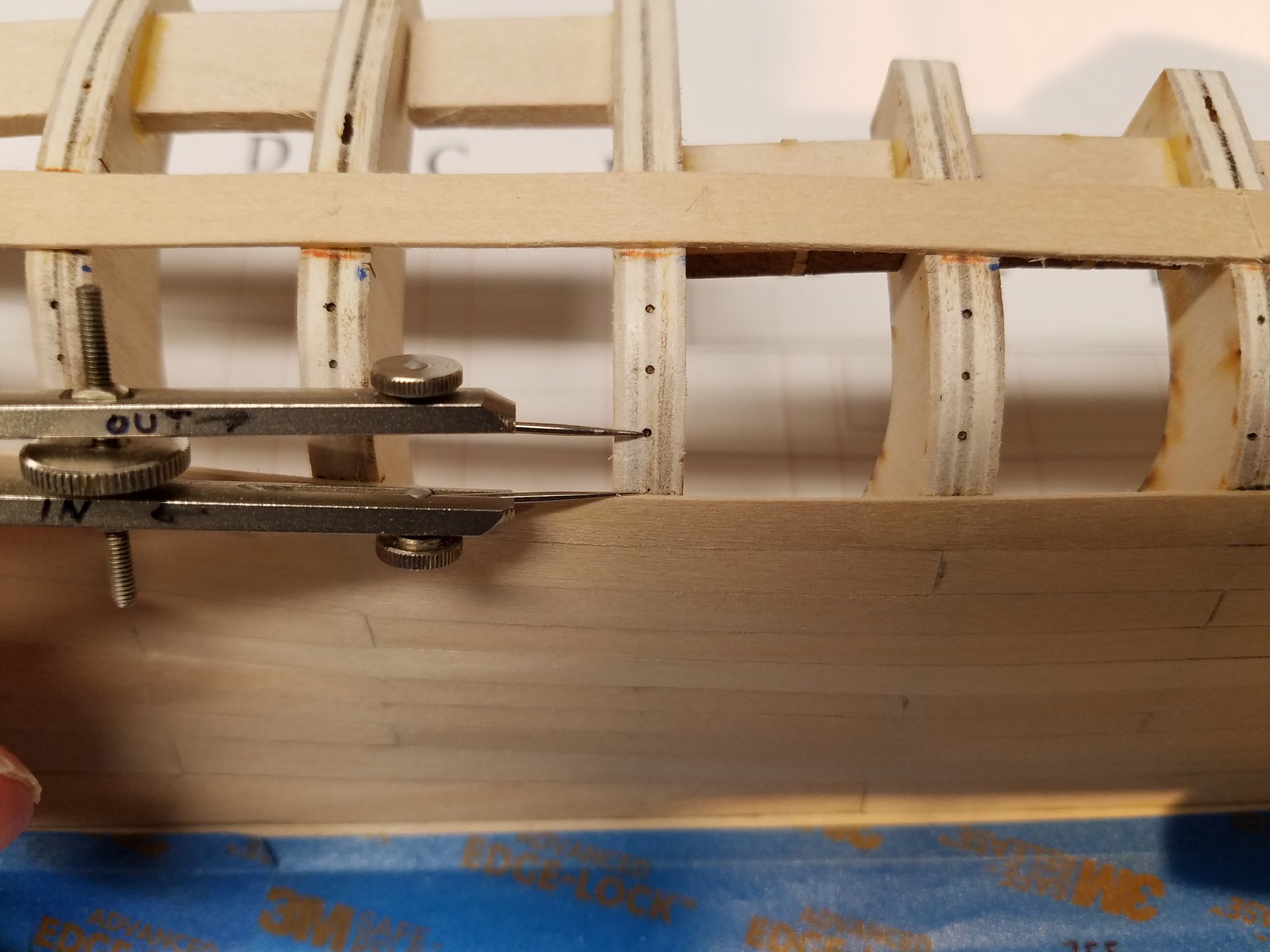
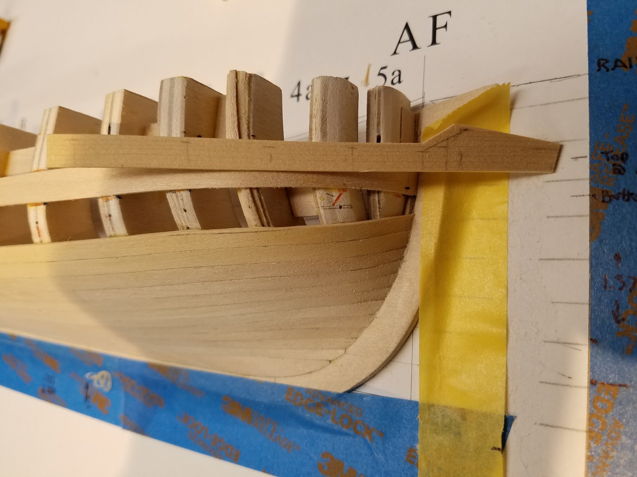
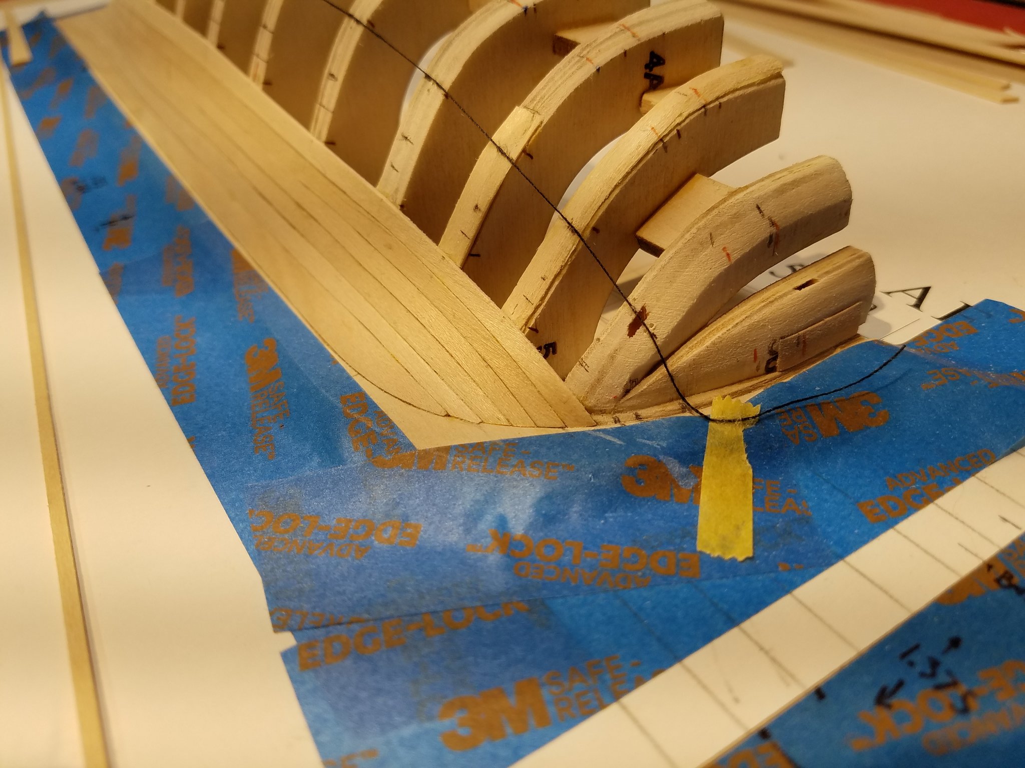
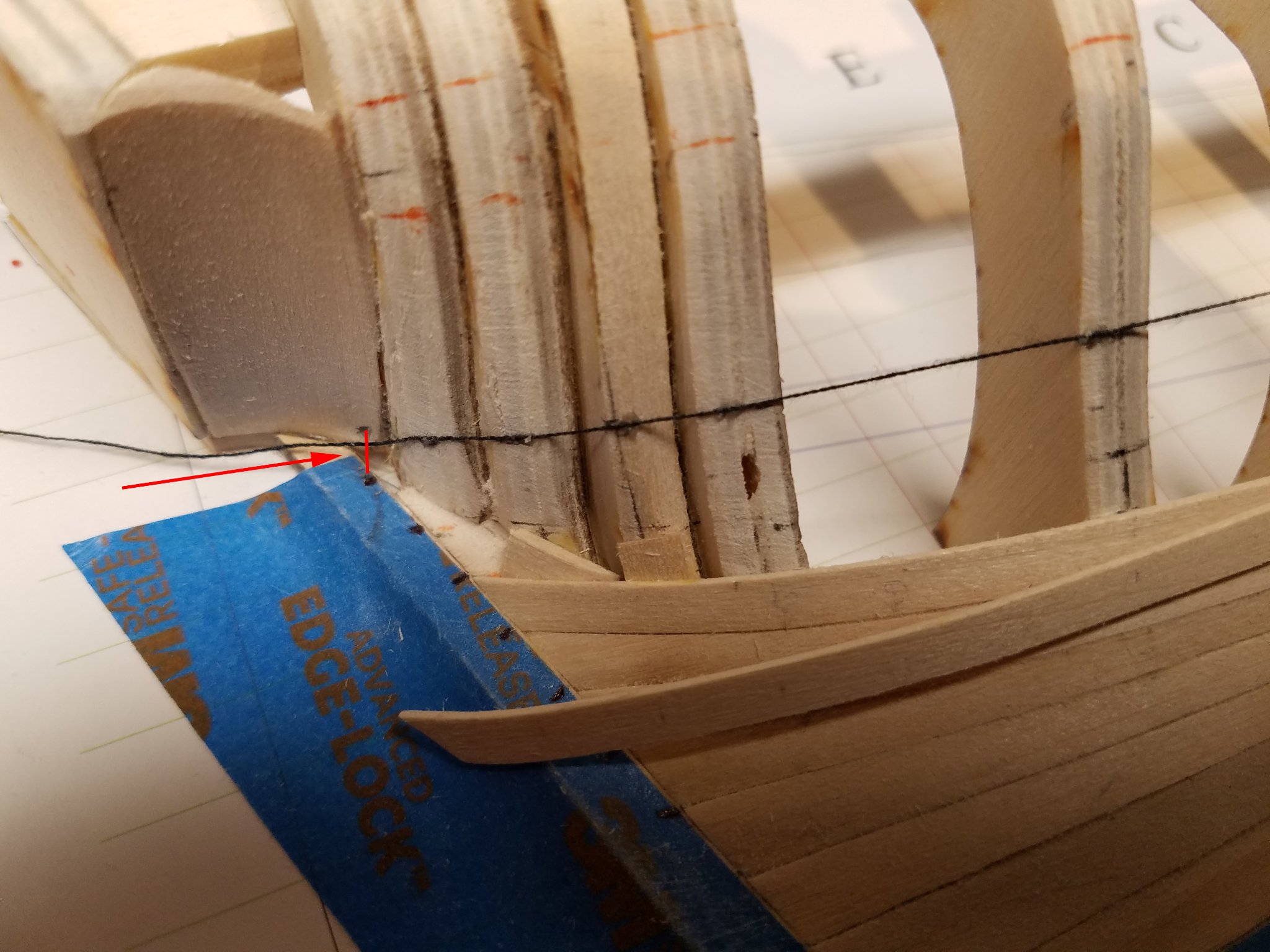
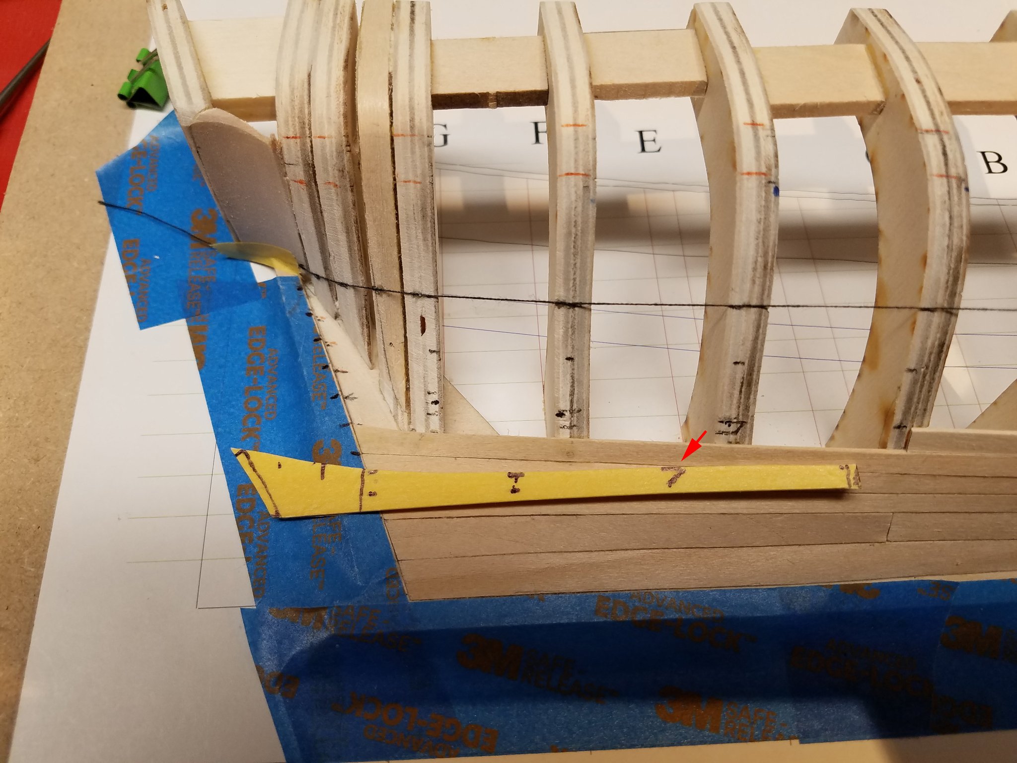
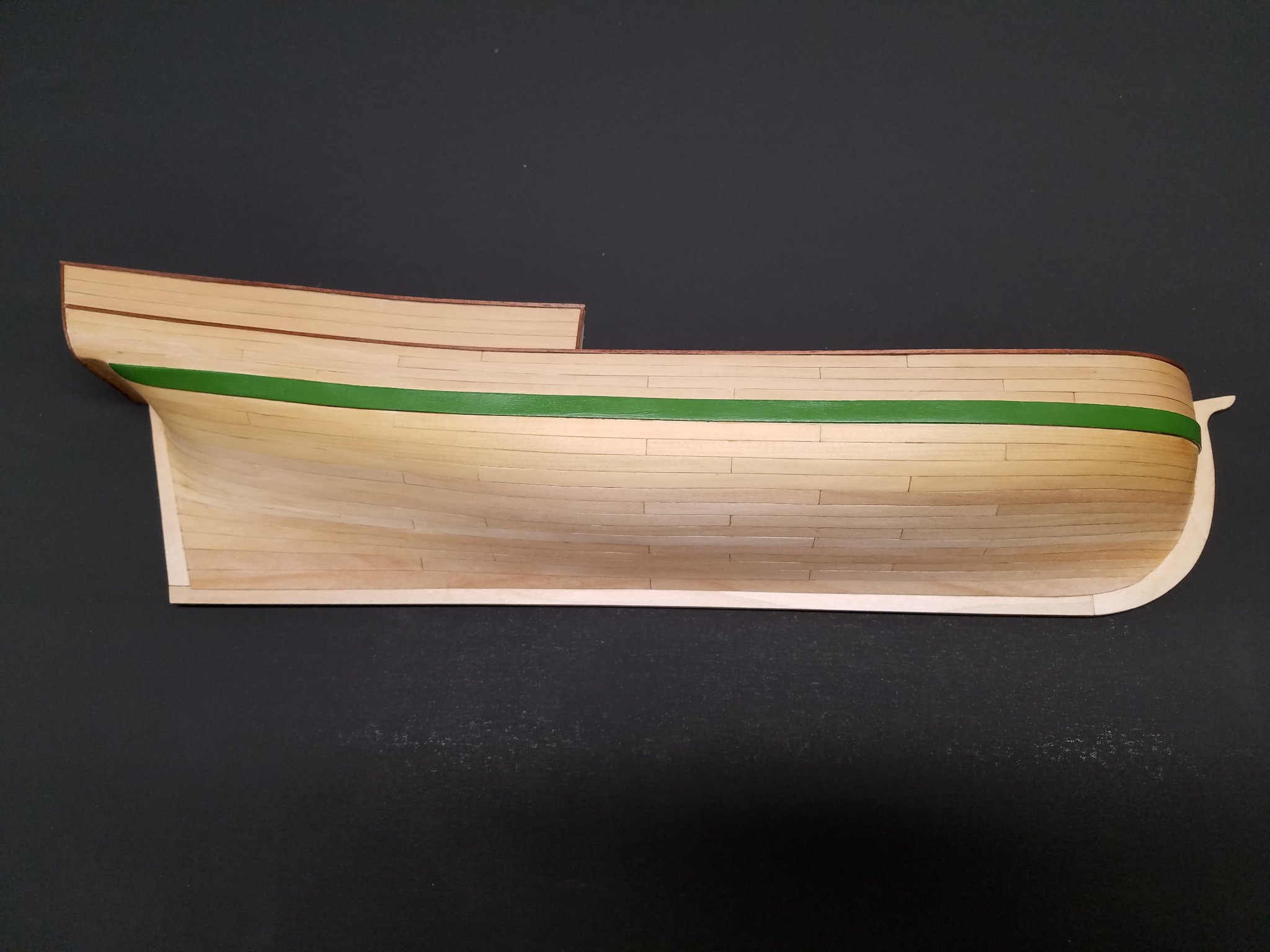
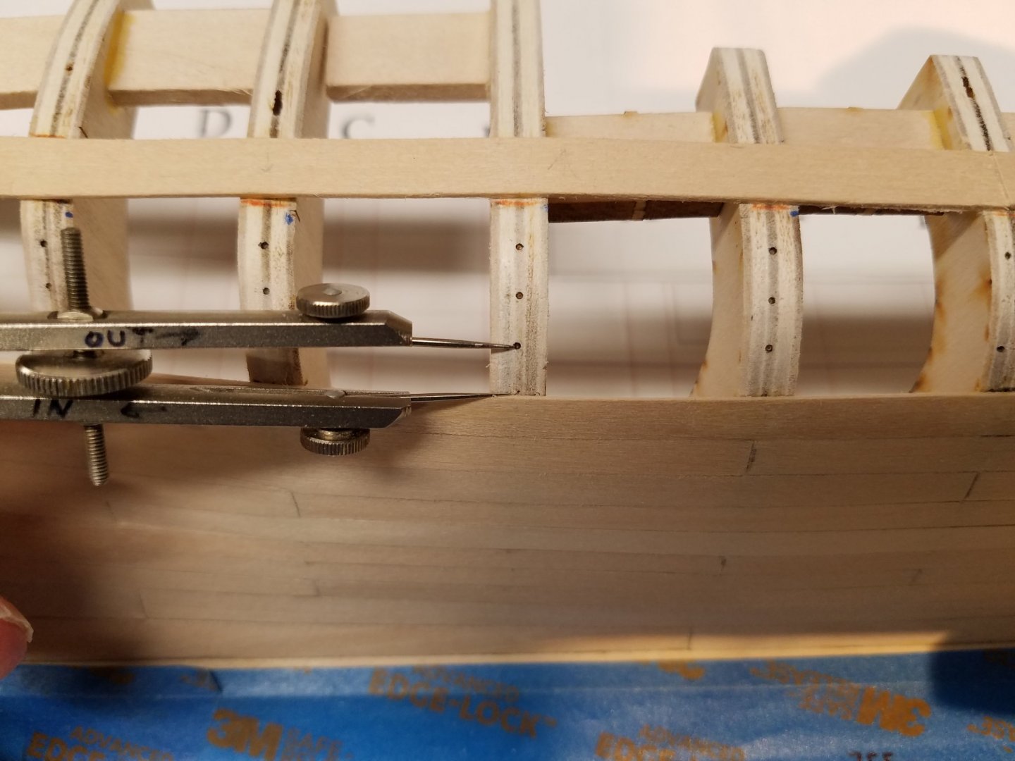
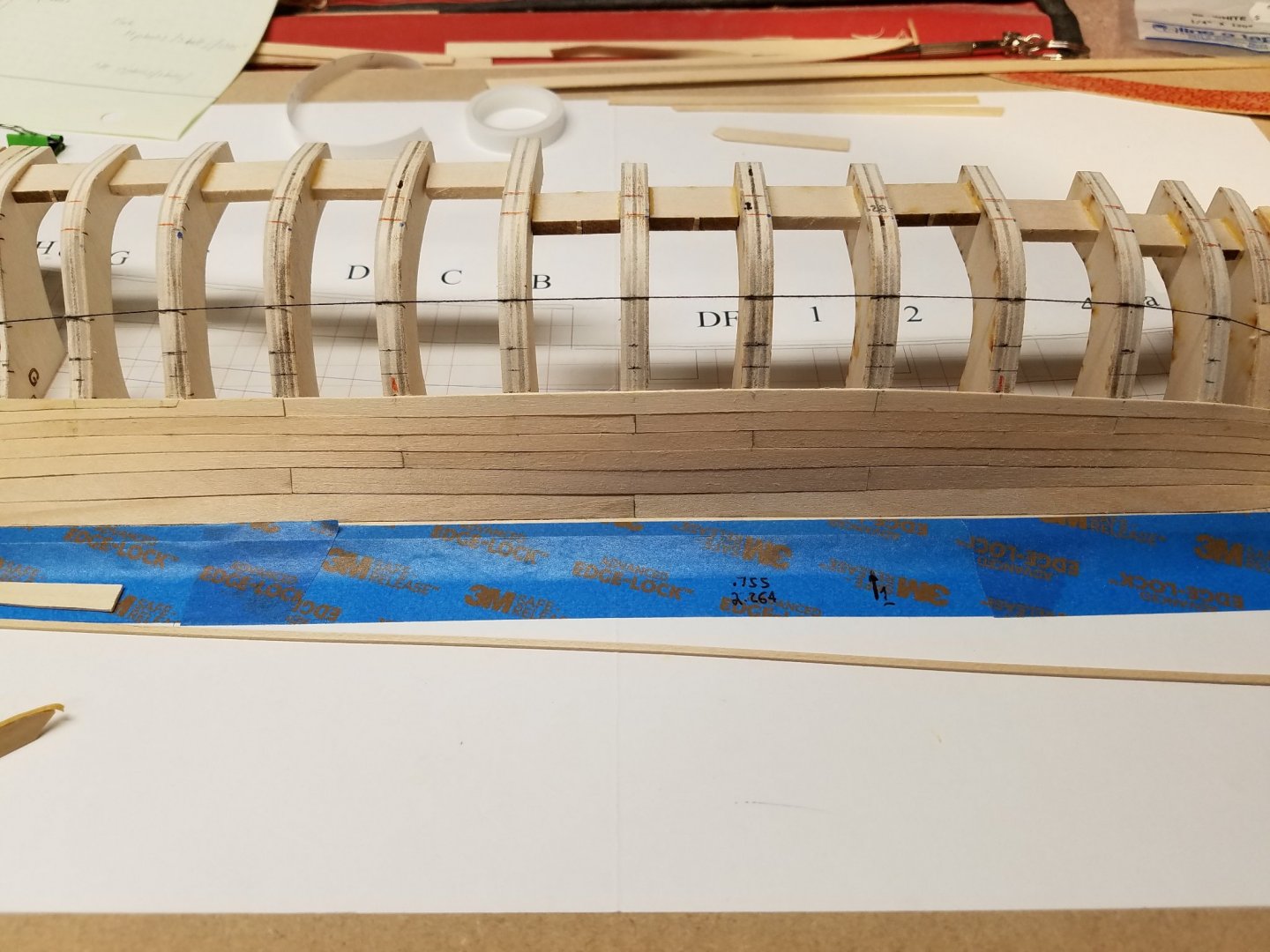
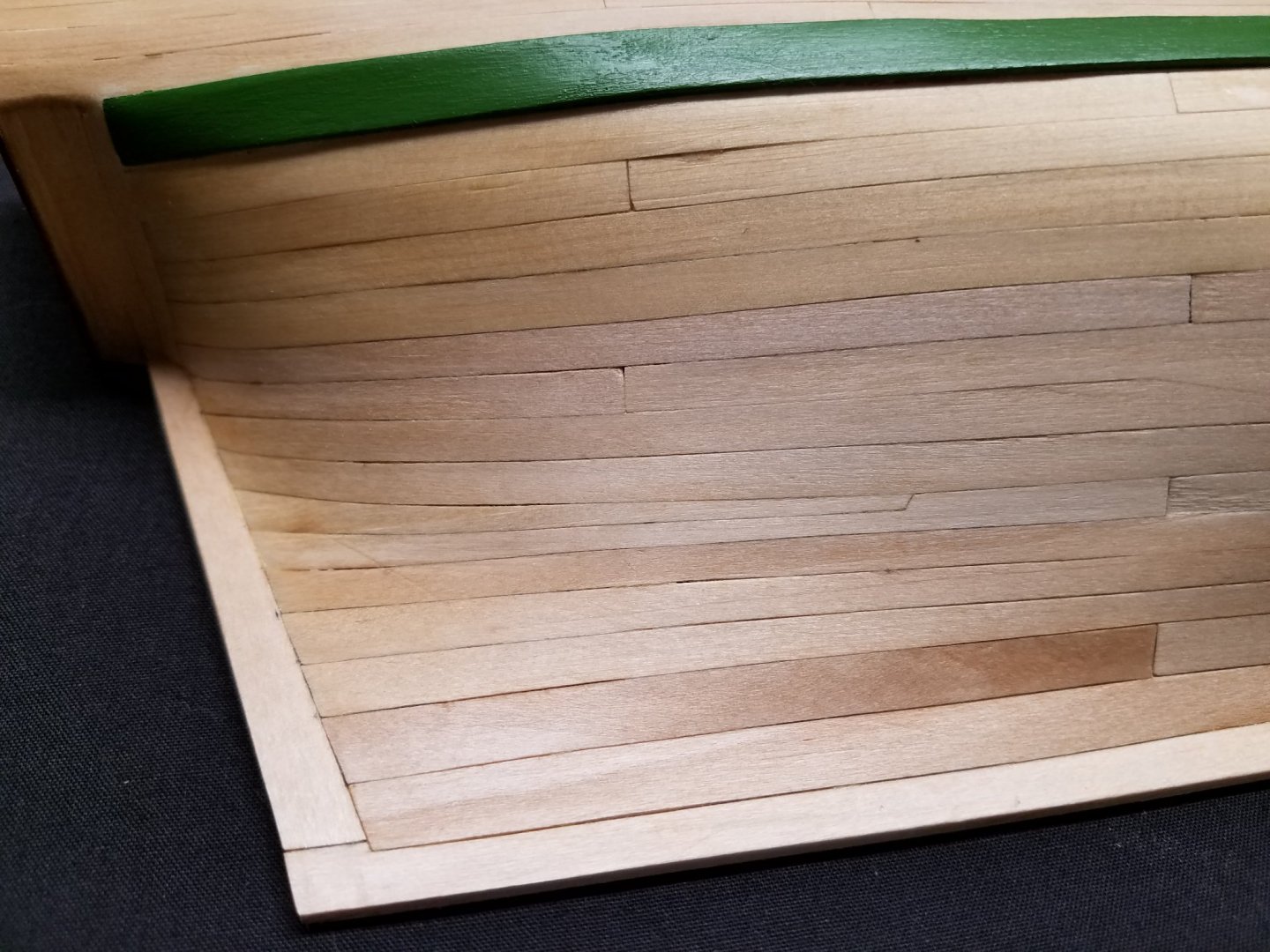
... 1-19-21 Thank you Ryland for the like. Much appreciated. The wale finally goes in. Still uncertain of the where/how the upper edge of the wale should align with the counter and transom, I took the ques from from Toni's project. In this case, right or wrong, the the upper edge of the wale is in line with the lower edge of the curved shape of the transom. Once the counter is planked, there should be enough material for the next plank up, to be blended in with the counter and transom planks. Temporary battens were put in for the 3rd belt planks to land on. Finally, the wale is in. I held off marking belt 3 until the wale was in. In this shot, I'm trying a different way to mark off the frames for use in the case of laterally bent planks. No measuring or tape is involved. The divider is adjusted/walked up the frame/re-adjusted to get the correct equal spacing. Then divider points are pushed in a little then sharp pencil highlights the hole. 1 The plank is cut a tad larger than the largest space then re-marked with a divider/pencil at the frame positions. The markup looks like this. it's way oversized because it's a drop plank.... my first. 😬 Mike


-
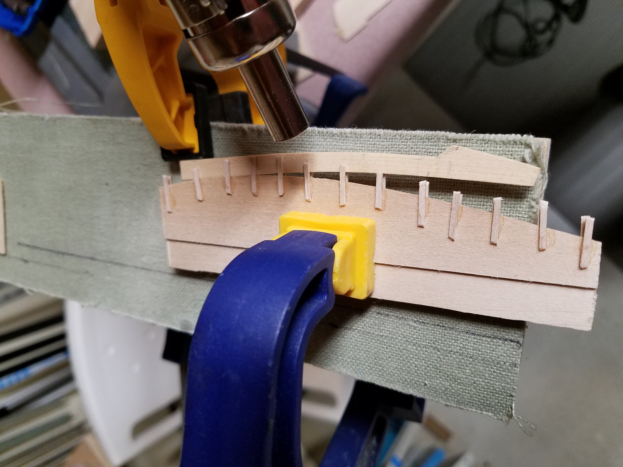
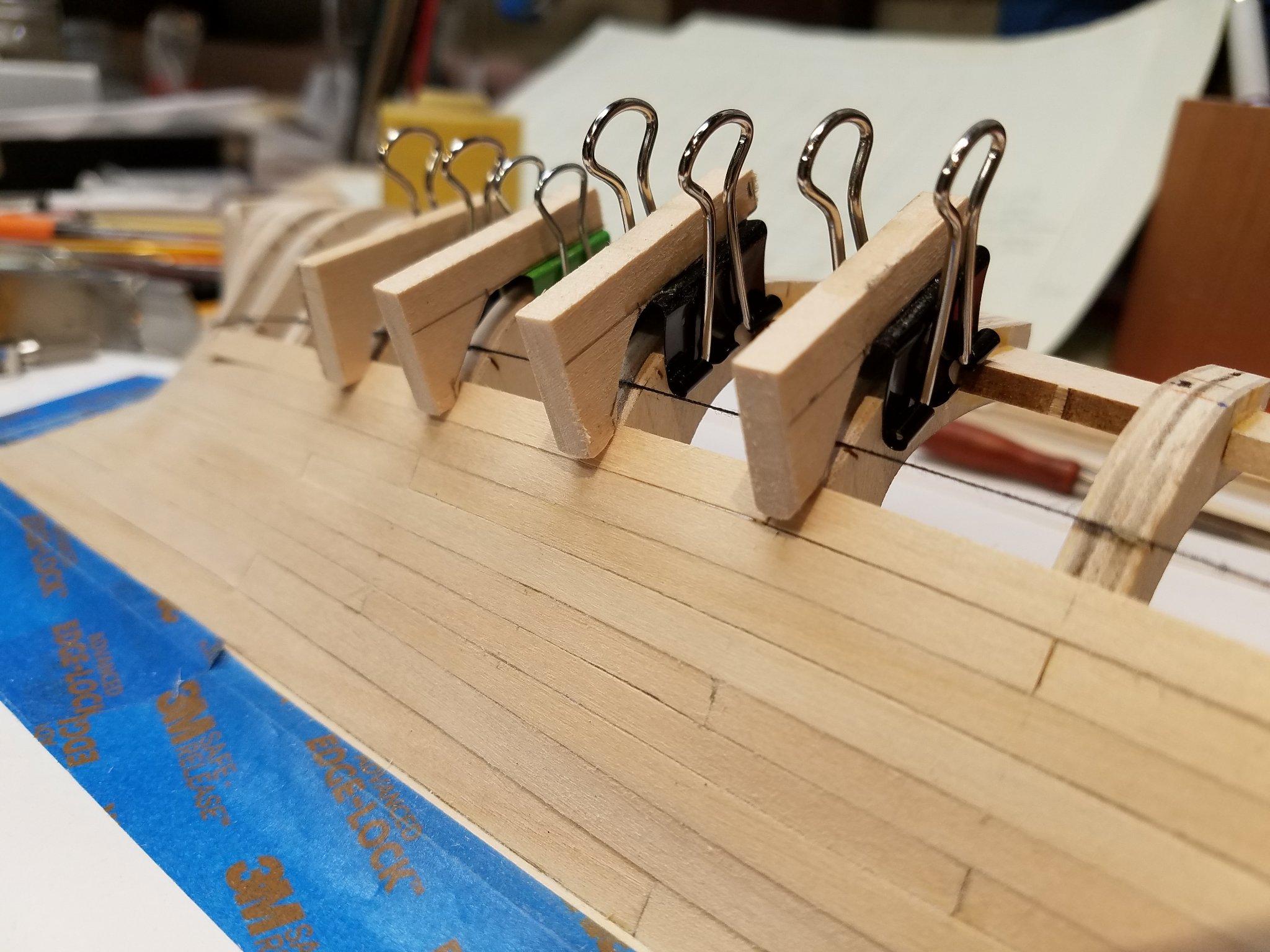
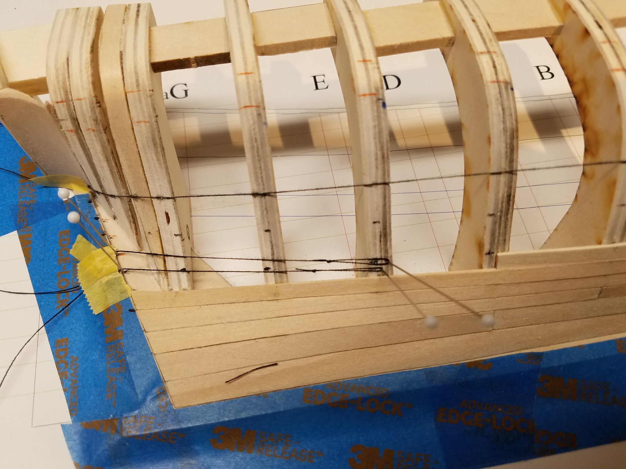
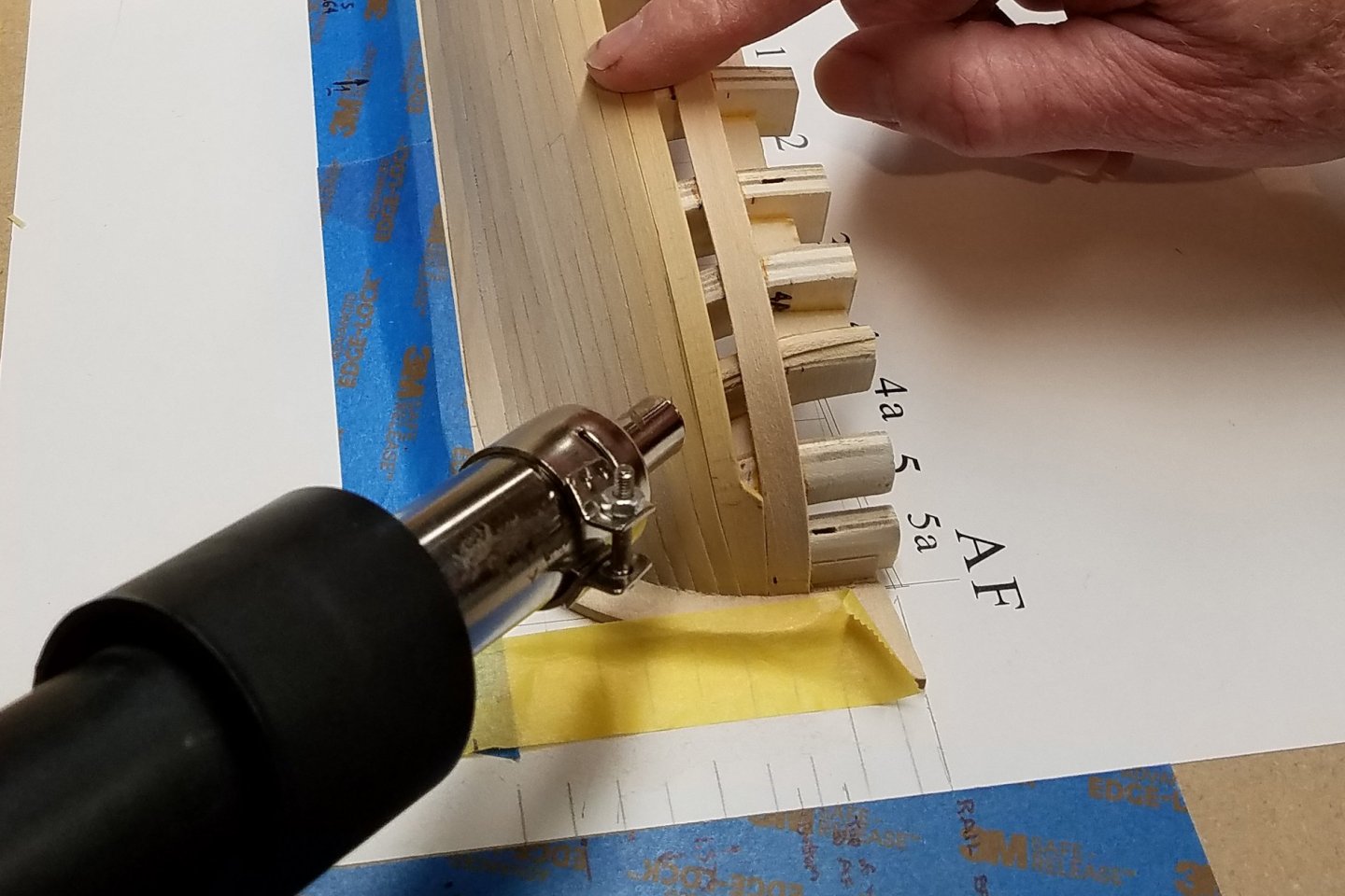
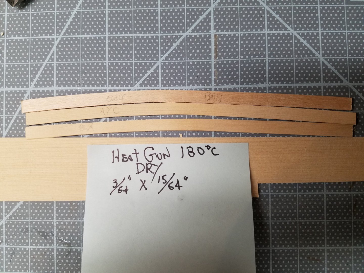
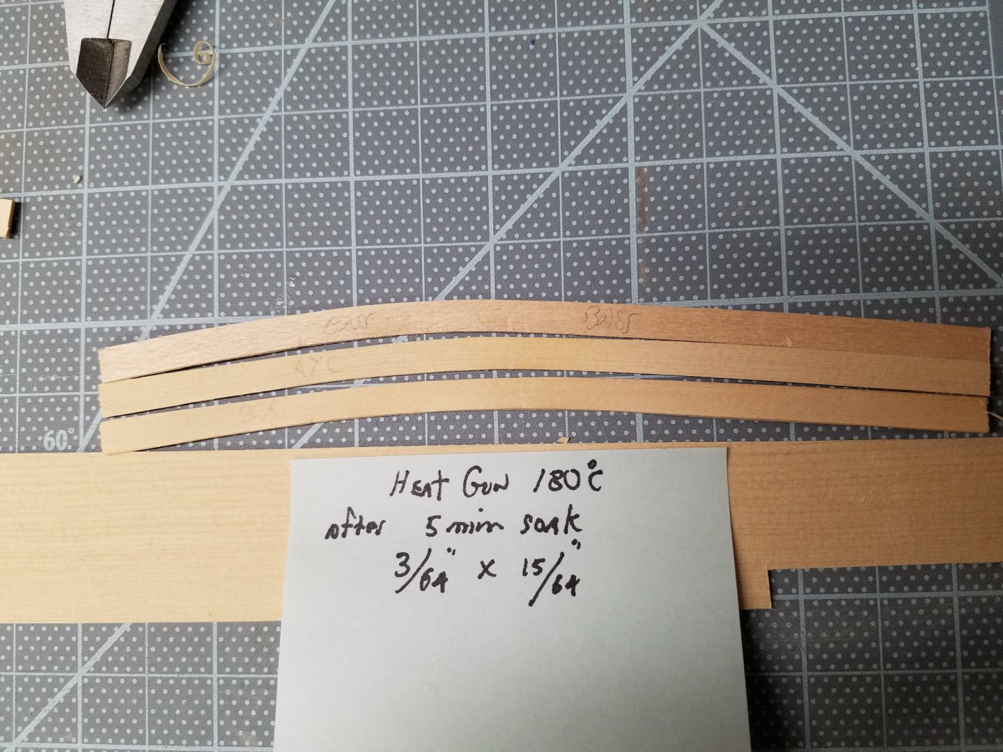
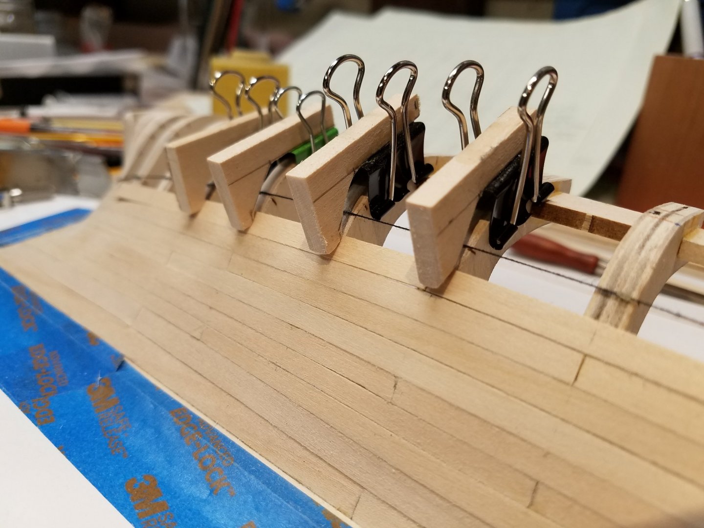
1-15-21 Between the first and second belts, I practiced bending planks laterally instead of cutting them to shape. I like this method. As long as the upper edge of the lower planks have been smoothed, the lower edge of the next plank above can snug up nicely with very little pressure. Notwithstanding, there is a limit of how much a plank can be bent laterally. For my electronics hobby, I use a temperature controlled heat gun typically used for soldering surface mount devices. A temporary jig was made to do bending tests of bass, box and AYC in the lateral direction. Side stiffeners were a must to prevent warping. The jig worked well enough to make version 1.1 for the next project. This is just a simple bending test of DRY 3/64" x 15/64" x 6" bass vs AYC vs box in the above jig. The dry bass and AYC bend about the same while the box is is less bendable. The same pieces were bent again after a 5 minute soak in room temperature water. All three pieces increased their bend when using water. Especially the bass. Using heat bent bass with light clamping. For minor bending, just finger pressure is needed. Mike

-
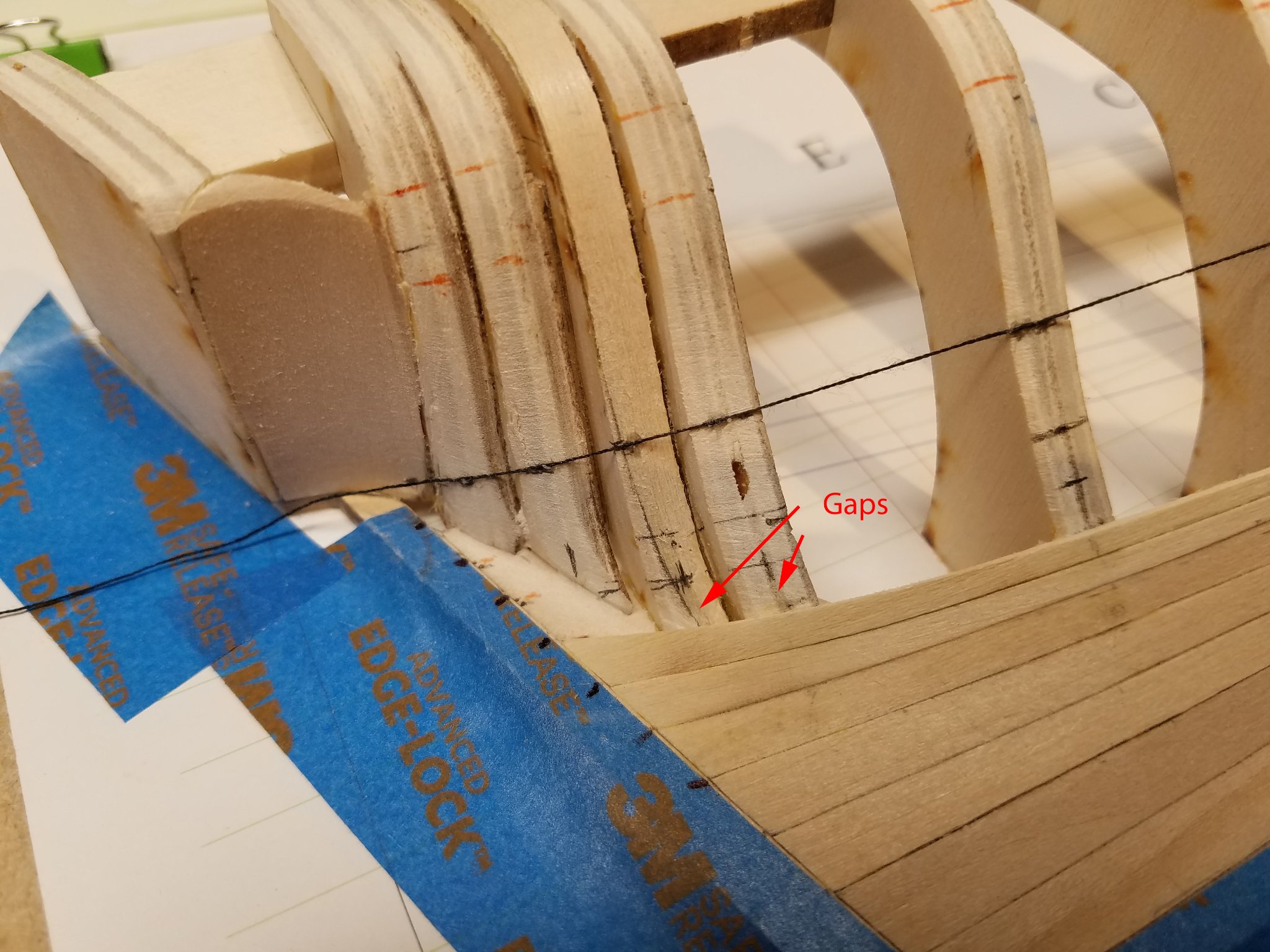
... 1-11-21 The first belt is finished. The method i have used up now is the same that Toni used in his project. i.e. apply masking tape to the frames, mark the tape, apply the tape to the wood and cut out the plank a little large. Then, trim to finish. (Toni's Post #31). This method worked fine for me from stem to stern on belt one where the final quality of the fit became a matter of time (and wood) spent. It's hard to see in this shot but gaps are showing at G & Ga in spite a Ga already having a shim. ... 01-14-21 I've yet to develop a good eye for fairing the tricky frames. 🧐 Note the last plank in this belt straddles the stern and counter. Mike


-
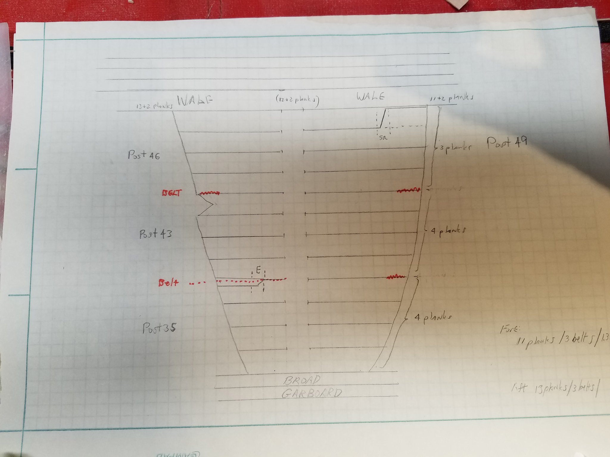
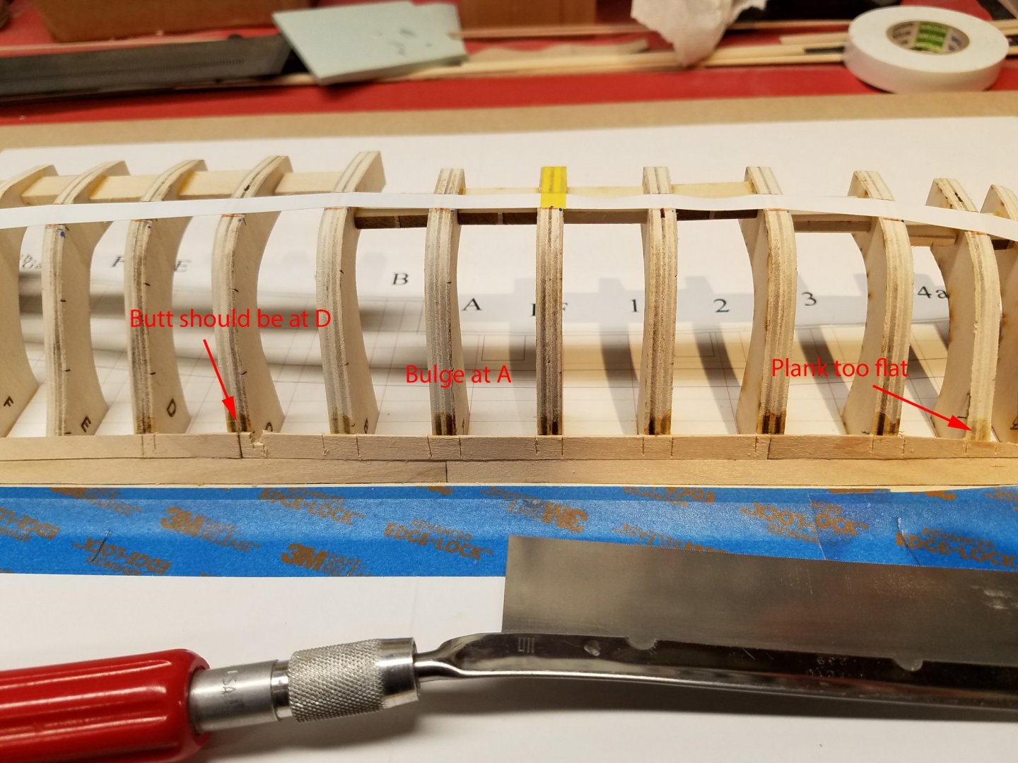
... 1-1-21 Happy New Year! Thank you for the likes. I really appreciate your checking in. The best way to make 3 mistakes is to do it all at once and get it over & done. Maybe I worked on this on New Years eve but when I looked at it in the morning I see a butt position is wrong, a bulge at frame A and giant flat area on the fore broad plank. Out comes the razor saw and the evidence is destroyed. No one will know. 🧐 Titebond is used only at the frames. I try to avoid glue squeeze out on adjacent planks so no collateral damage. ...01-06-21 The belts were laid out as closely as I could following Toni's project. The thread is tacked lightly to keep it in place. The white tape is cut to width for the wales. However, at this point I really didn't understand where and how the wales should intersect the aft most frame and the counter. The wood used is from inventory. I'm trying to learn the working properties of bass, box and AYC regarding bending, shaping, finish, etc. Before getting to the aft stealer, for my own clarity, I drew up my understanding of Toni's planking layout. .. 1-10-21 I tried using thread to layout the aft stealer lines but did not get smooth curves. I decided to make one larger plank and split the stealer off. Larger plank piece to be cut in two. Some dressing up needed after cutting out the stealer. Note the change from basswood to yellow cedar in the above shot. Mike


-
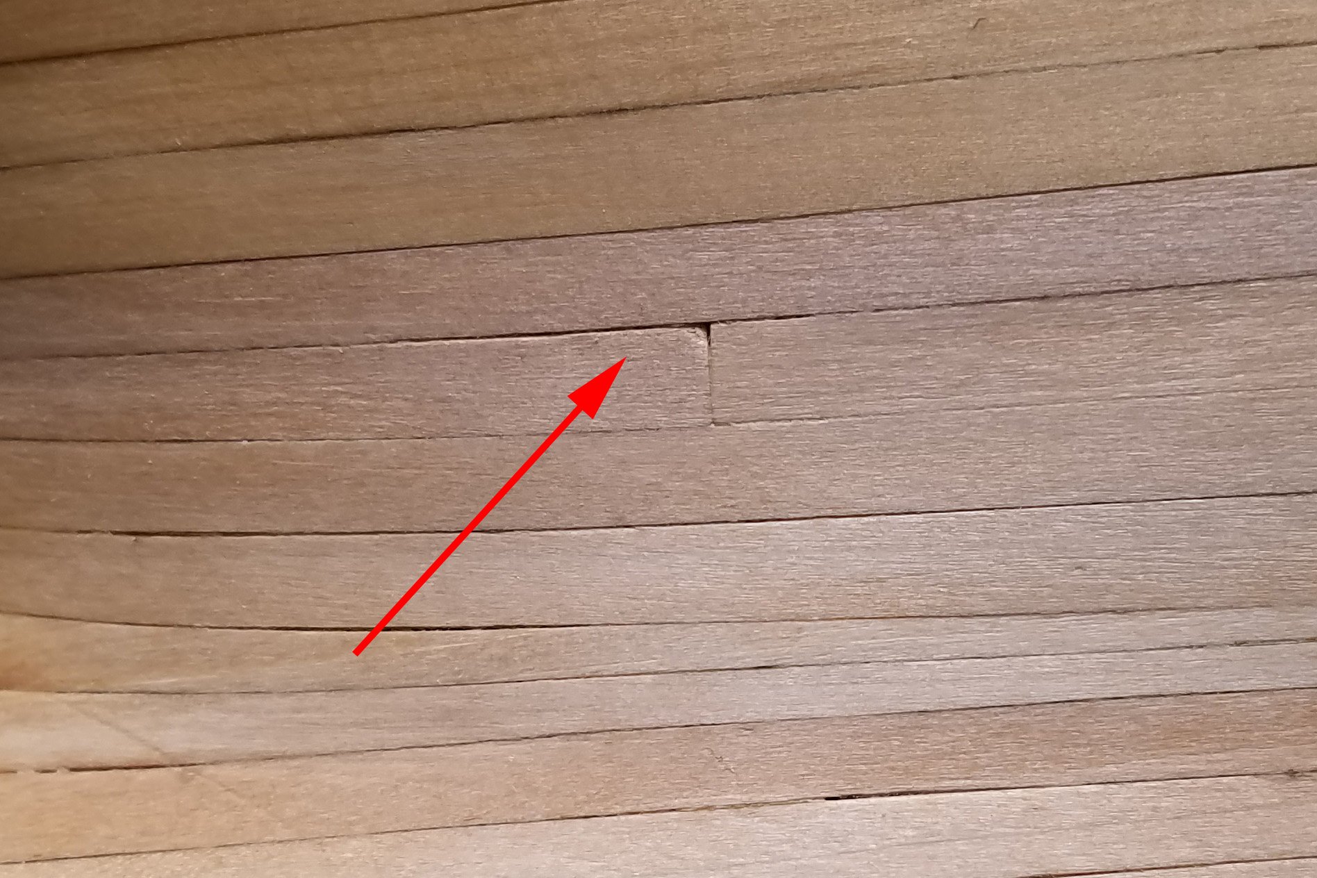
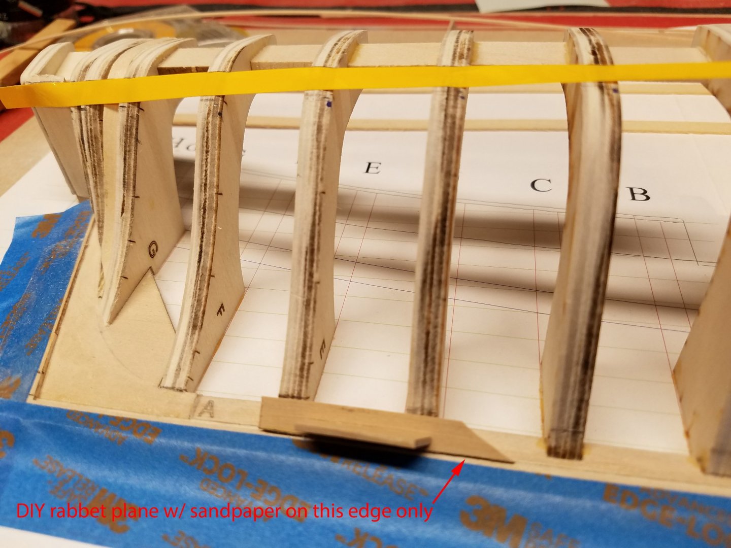
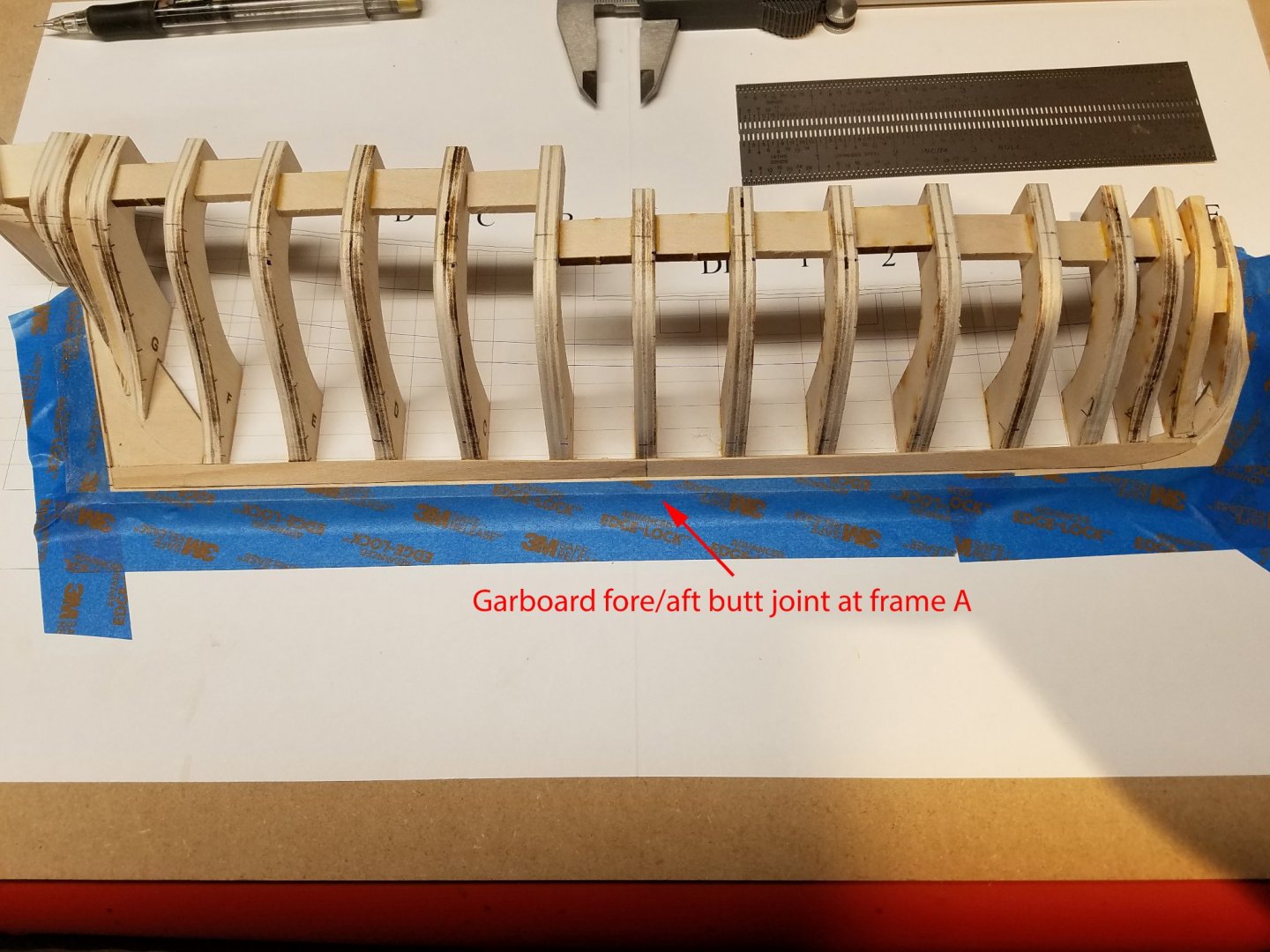
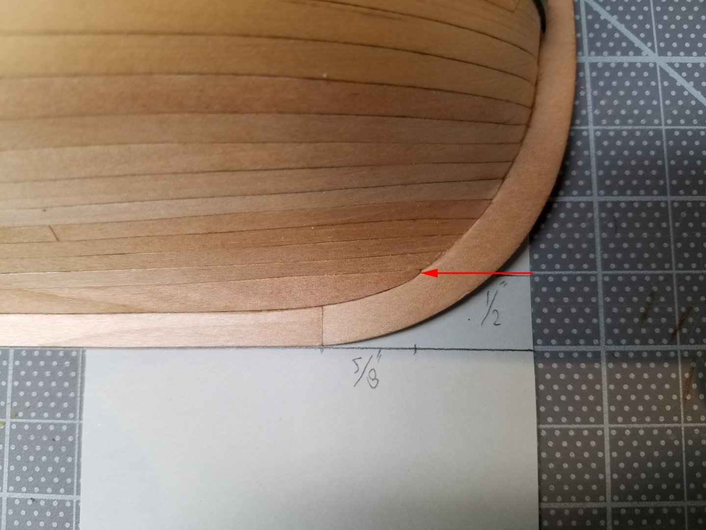
...12-30-2020 This was my favorite tool throughout the project. I made three different lengths. The thin edge is 1/32" wide and had 220 grit sandpaper glued to it. In this case it is used to sand the keel rabbet only on one surface at a time while twisting it a bit to blend the rabbit from the flat angle aft to more steep angles going forward. Based on Toni's advice in his project, the garboard plank butt joint is placed at frame A. A word about butt joints. I learned 6 or so planks too late that it's very easy to over sand the end of a plank and not notice it until after it is glued. When the next plank goes on top, there is that gap. From there on, I tried to sand dead even or a little high. Then, with the thin sanding plane, get it even with the joining plank. To avoid the planking "smiley face" effect, the fore end of the garboard plank was place as shown. Now that I'm zooming in on the shots, I see top of the garboard, just a little back from the stem, should have been shaved down to allow a little wider broad plank.... reinforcing my choice to do a practice project. 🙄 Thank you guys for the likes. Mike

-
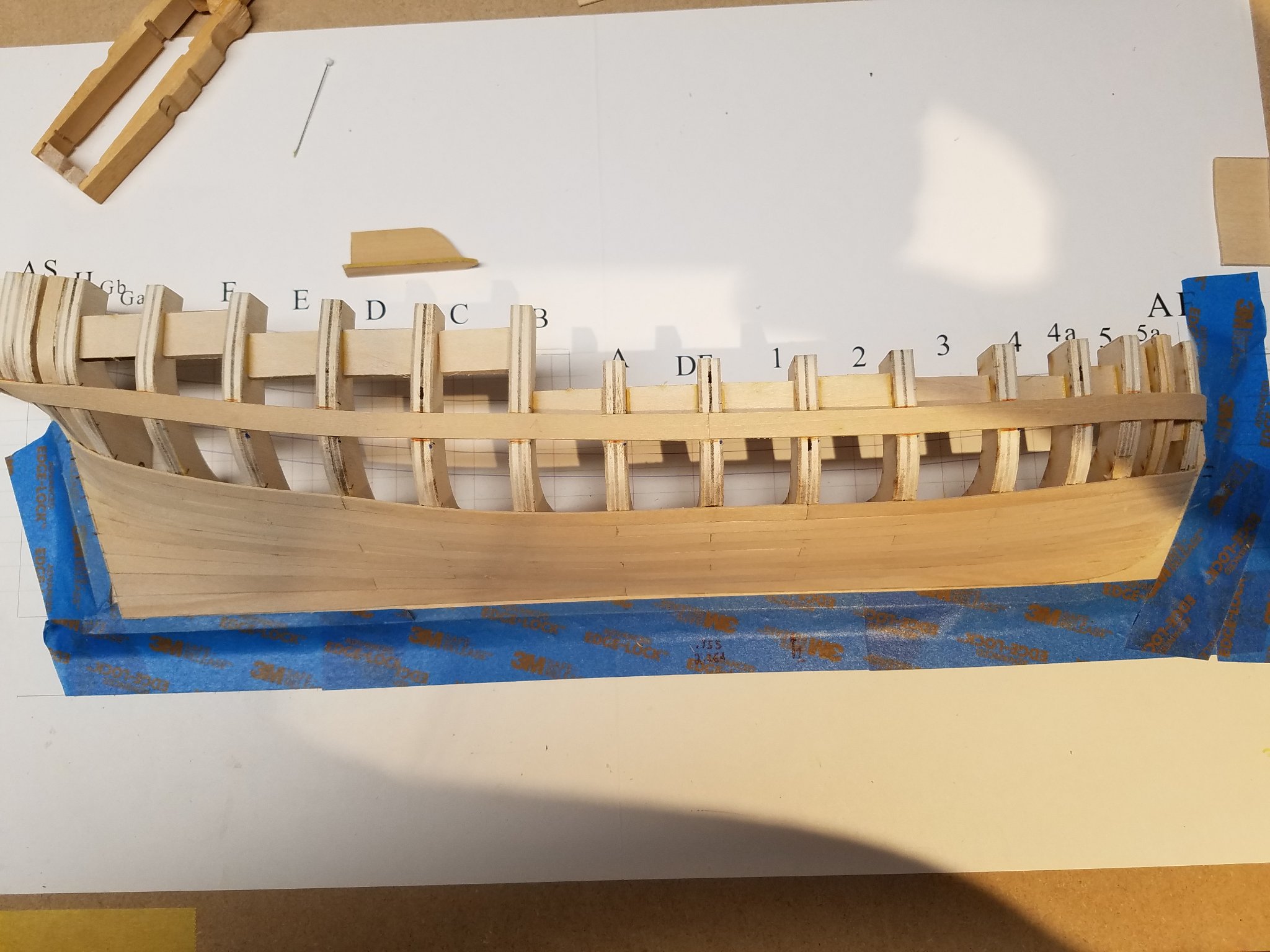
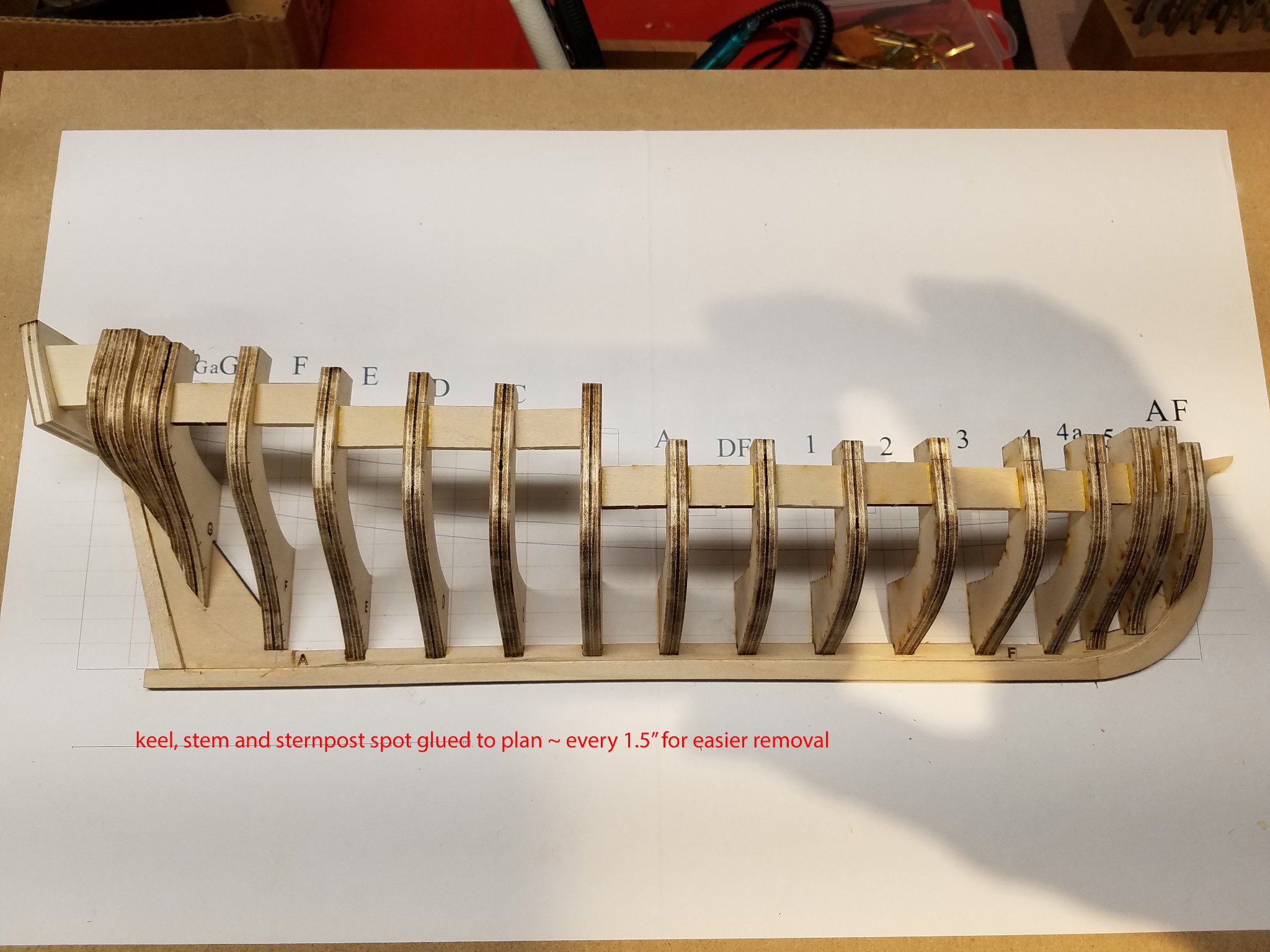
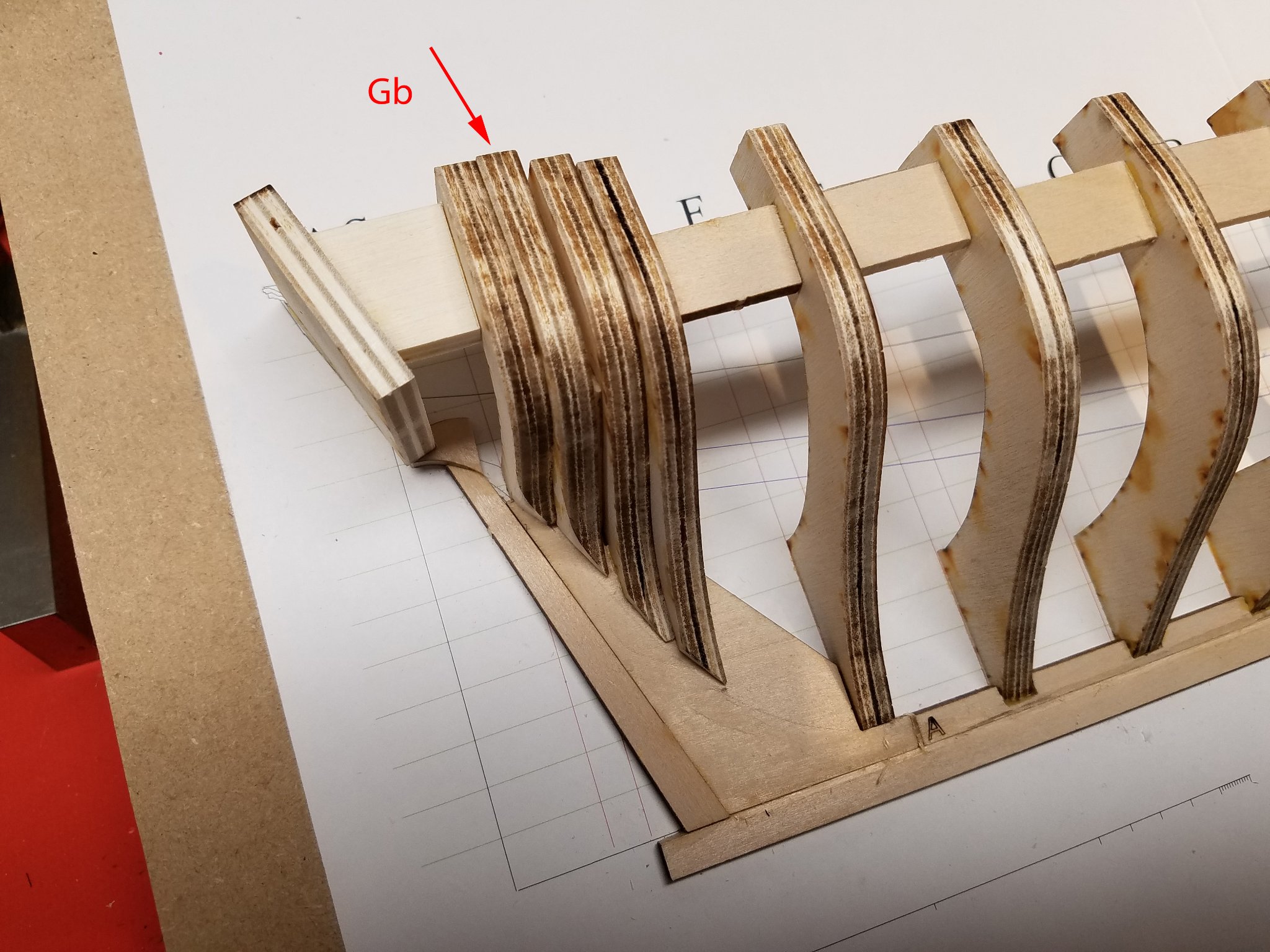
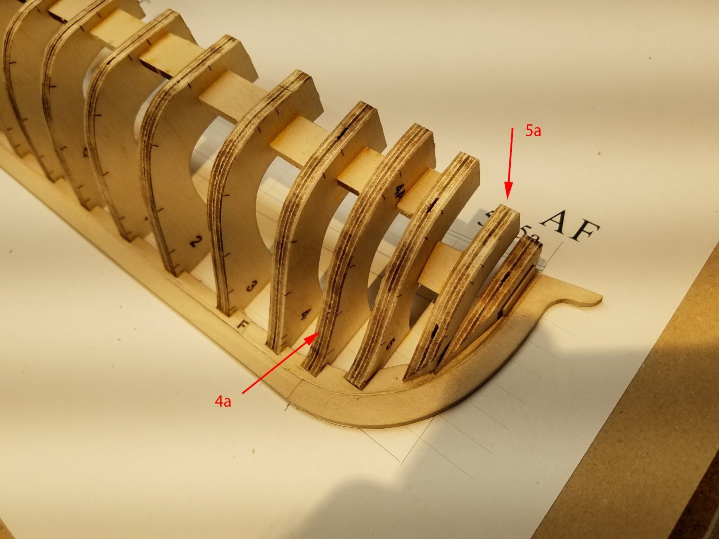
... 12-24-20 The masking and 2 sided tape are now removed so ready to start work. The rabbet marked out, scored at the appropriate angles then cut in with a 1/4" sharp chisel. ... 12-25-20 Merry Christmas The plan was spray glued to 1/4" MDF. I was worried that the hull detachment from the plan would be difficult so the stem, keel and stern post were only spot glued (PH neutral PVA) while the "base" contact area of the bulkhead to the plan was completely but thinly glued. The stiffening blocks and transom were added. Of course, a few bulkheads were off and shims were needed at Gb..... .... the lower part of 4a and 5a Any tips, correction or comments are always welcome. Mike


-
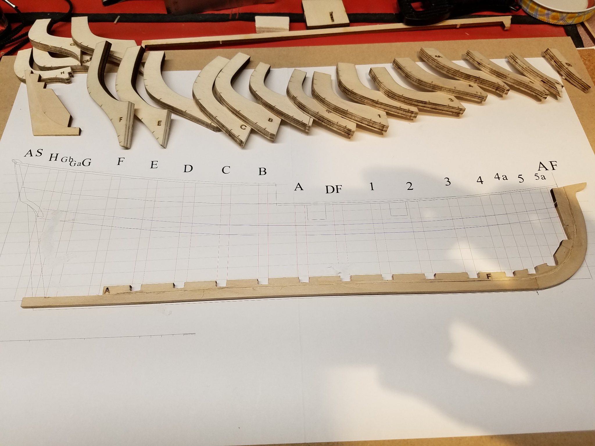
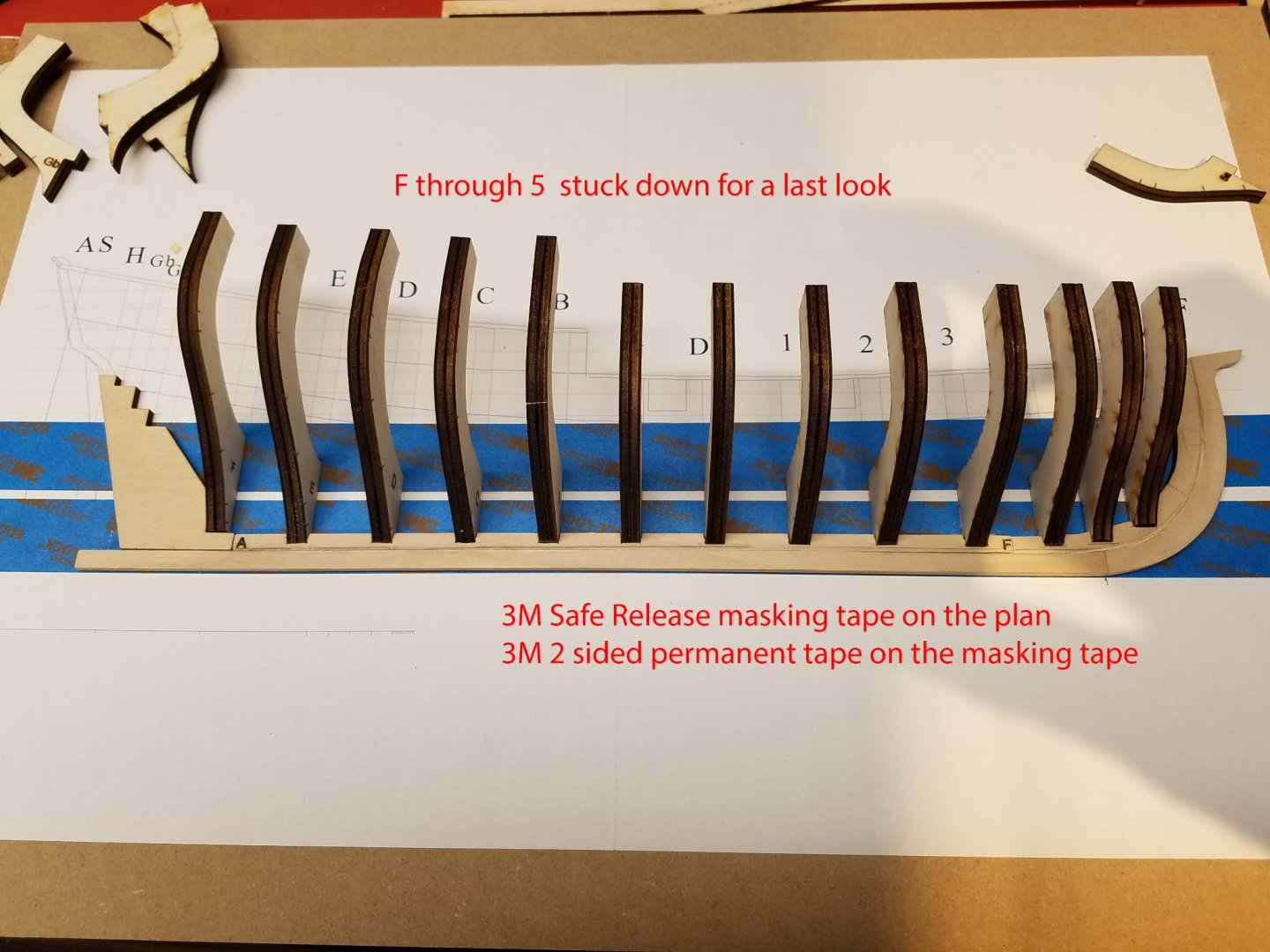
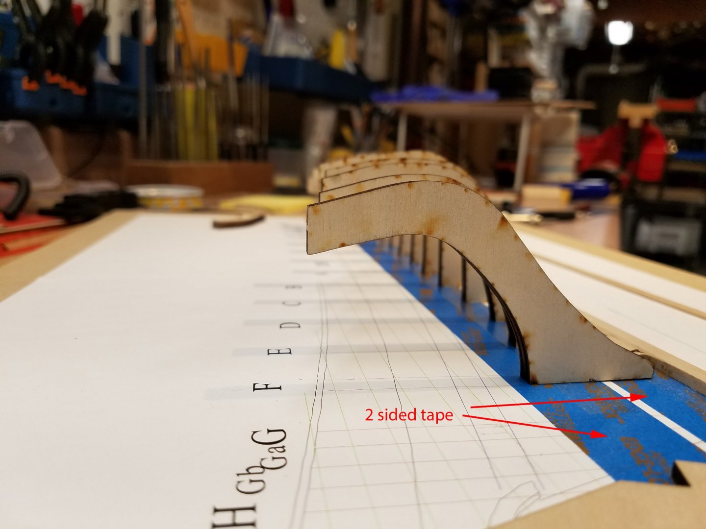
...12-23-20 A similar method was used to check the top rail alignment with the plan without gluing the bulkheads to the plan and keelson just yet. Two rows of an easy release masking tape were put on the plans and two rows of 2 sided tape attached to that. This shot includes the F through 5 bulkheads. This method worked well for me. No shims were need on any F through 5 bulkheads bulkheads. However I apparently lifted E too high which caused a bulge near the top of the rail. Shims were needed on Gb, 5a and 4a which could not be included in this method. Mike
-
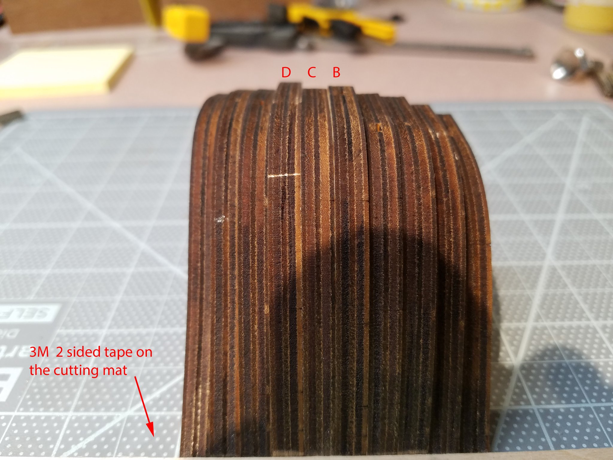
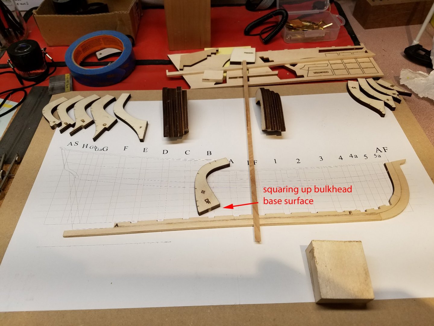
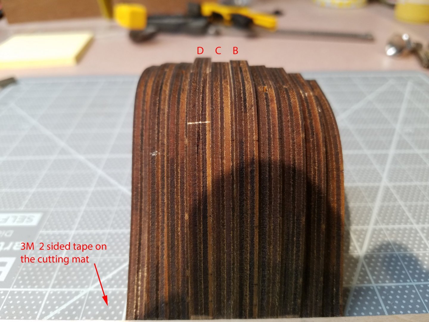
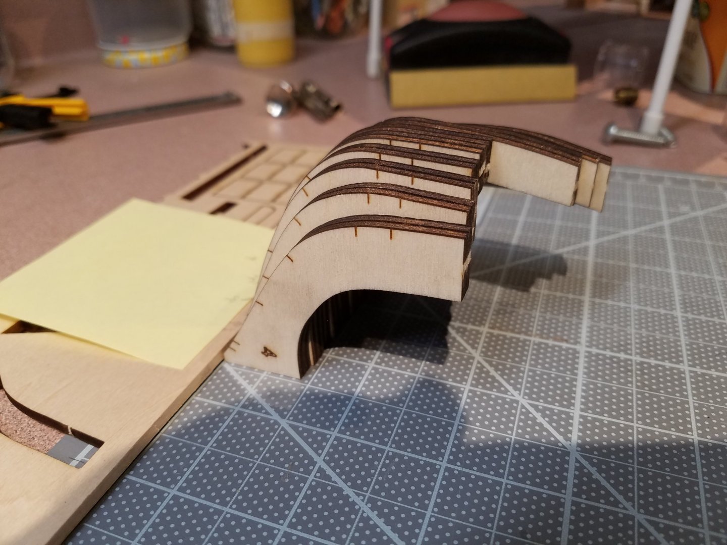
... 12-23-20 The completed half hull logs logs on this site were a huge help in avoiding pitfalls and I especially followed Toni's half hull log. The kit wood and single sheet plan were great and the only real issue to deal with at the beginning was the laser burn through on the bulkhead bases that unavoidably cause an off square angle. In that the bases are to be glued to the plan, they will affect the outside alignment of the bulkheads. They were squared up on the disc sander taking off the least amount of wood possible. Half bulkheads are awkward to stack up for a preview of their fairing. Frames E through 4 are aligned at the same level into the keelson. So (fingers crossed) 3m "permanent" 2 sided tape was used on the cutting mat to to get a first look at how the bulkhead base geometry will affect the outside of the bulkhead alignment. In this case the C D E group would need adjusting. The tape worked quite well for about 20 minutes before the bulkheads tipped over.
-
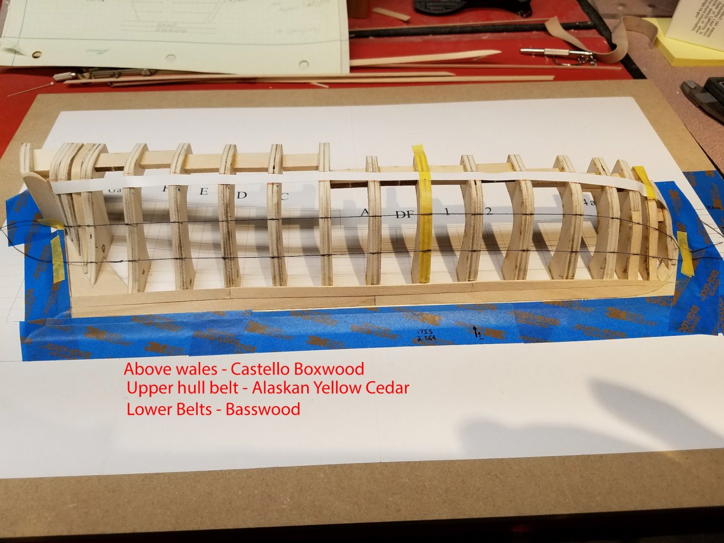
In dire need of planking & spiling practice before tackling the next project, I was so pleased to come across NRG 18th-Century Merchantman Half-Hull Planking Kit . Actually, this project was started just after last Christmas as a present (to myself) and is now just about finished except for the mounting. I knew I would be dragging this one out because I would be experimenting with different wood, adhesives, wood bending, finishing, etc. and wanted all that to be done on one model rather than one model at a time. That being said, there would be large gaps in posting the log of a relatively small kit. Mike

-
Hi, from an absolute rookie from Barcelona
Mike_In_RI replied to BCN-Modeller's topic in New member Introductions
Hi Pascual. Welcome and best of luck on your first project. May I suggest to look at the "More" menu at the top tool ribbon on this site. Is has some really good articles incuding about planking. Your boat looks like a great one to practice that. Mike -
Great improvement of your wheel over the kit version. Also the weathering of the wheel house cabin, especially the table top, is perfect. I can almost see a stain there from a bottle of 12 year old Glenfiddich. The LED lighting was well worth doing. The color is perfect for the camera.
-
Very nice job on the compass, harpoon gun and weatherizing . How's your eyesight? Working on the compass was about the time I got a new OptiVisor. 🧐
- 104 replies
-
- 2
-

-

-
- model shipways
- new bedford whaleboat
- (and 1 more)
-
Hi John, sorry I missed your build up to this point. Once I have a project my head goes in to ostrich mode. In any case, your whale boat looks great. The color choices and weathering are super. Yes, no end to the tiny pieces yet to be made. "Micro Carpentry" ... exactly. Mike
- 104 replies
-
- 2
-
-
- model shipways
- new bedford whaleboat
- (and 1 more)
-
Hi John, thank you for you interest and compliments. It's a great kit. Well, actually I'm almost finished with the next project which is the NRG half-hull. I haven't posted up on it yet because I've been using it to experiment with different types of wood, wood bending, planking methods as well as planking in general ... with which I sorely need practice. After that, I've been looking into the Charles Morgan, including your outstanding project on the forum. The Morgan is less than an hour away and I am a member of the Seaport. Or, maybe a Swan class project or one of Chuck's kits. I haven't seen yours whaleboat log yet.... I'll jump there very quickly. Mike
- 128 replies
-
- 1
-
-
- model shipways
- new bedford whaleboat
- (and 1 more)
-
Jean-Paul, I have just now seen your project. You are off to such a great, well thought out and crisp start. Not only that, you seem to be having a lot of fun! Mike
-
Thanks Joe. The presentation is based upon a model built by Jim Shoesmith. I took a photo of it while it was in the basement level of the New Bedford Whaling Museum. They were gracious enough to take me down there for a look. ... just took a long look at your Benjamin Latham project. What a great job. The photo in Post #94, among many others, is so realistic. I'm forced to confess that I bailed out on that model (very) many years ago when my planking skills were in short supply. At least with the MSW forum, I may yet stand a chance. Mike
- 128 replies
-
- 1
-
-
- model shipways
- new bedford whaleboat
- (and 1 more)
-
I meant to mention most of the shots I've seen come from either the Scottish Fisheries Museum or the Swan Trust in the Galleries section. https://www.swantrust.com/ .
-
That's fantastic ... and scary looking! And thanks for the time you spent at Mystic. The volunteers there are great. My wife and I go there a lot.... well, I drop her off for shopping at the Village while I go into the into the Seaport. I'm considering the Morgan as a next project since it is so close but the thought of so many blocks, etc. does not really appeal to me. Possibly a scratch admiralty model with below decks cut away may work. ... not sure. One question re: the harpoon. Is the shank of the harpoon hammer welded to the cone or is fashioned somehow as one piece? The cone part on the model was hard to make. Thanks, Mike
-
From all the wheelhouse pictures I've seen, they all look customized. Generally, I'd consider a small place for a chart as well. My guess is the wheel mechanism would be covered with a wooden cabinet/table which could also hold a small motor control and maybe even the binnacle depending on choice of it being cabinet mounted or on a pedestal. Spectacular as usual. Don't go too easy on the crew.. first coat hangers and seats... then leather cushions... pretty soon they'll want flotation devices and life preservers.. 🤔 Quick question... What did you use for window glass? Thanks, Mike
-
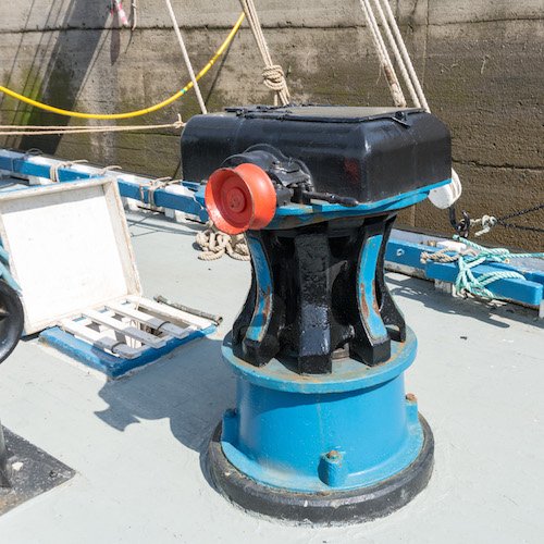
This from the Scottish Fisheries Museum.. https://www.scotfishmuseum.org/parts-of-reaper.php Maybe all that's needed is the boiler below and piping to and away from the box. (???) For that matter, the piping may well have come up axially inside the capstan (??) Mike
-
Another great update. Th photos are so realistic and crisp, one feels like leaning over to take a look under the deck. Mike
-
Yup, love the small parts detail of the boiler & coal bin... including the darkening of the floor planks from coal dust, of course. Mike
-
Leave out the nets... the fish will just be jumping into that boat! Great imaginative job as usual. Lights are a good idea. Mike
-
Great look on the deck house... mitered corners and all. The red features pop very nicely. Are you using a sealer on the basswood or going straight on top with the color? Mike