HOLIDAY DONATION DRIVE - SUPPORT MSW - DO YOUR PART TO KEEP THIS GREAT FORUM GOING! (83 donations so far out of 49,000 members - C'mon guys!)
×


Ben752
-
Posts
66 -
Joined
-
Last visited
Content Type
Profiles
Forums
Gallery
Events
Everything posted by Ben752
-
I was looking to get a 4 jaw sometime this year but given their prices rarely are discounted it looks like I'll be getting one this month. https://www.sherlinedirect.com/index.cfm?fuseaction=product.display&Product_ID=1507&CFID=140895239&CFTOKEN=82798041
- 1 reply
-
- 2
-

-
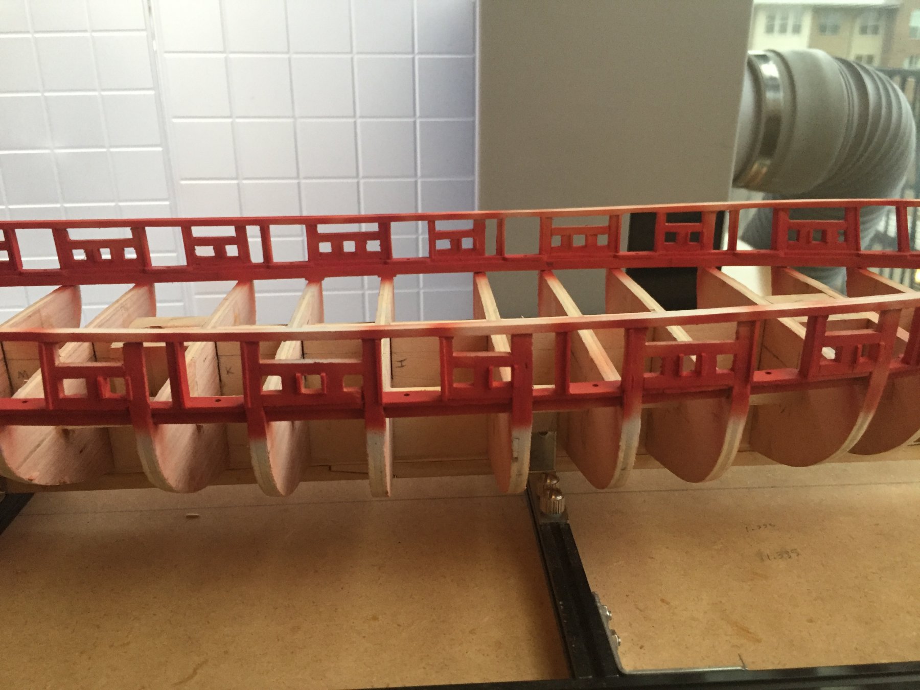
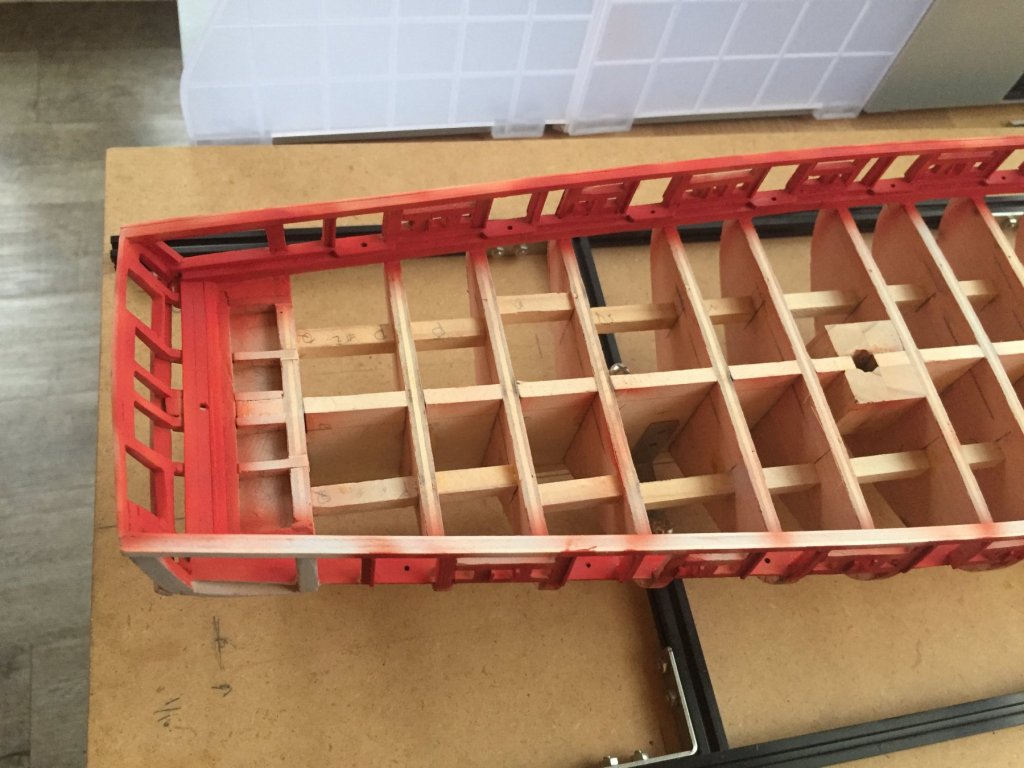
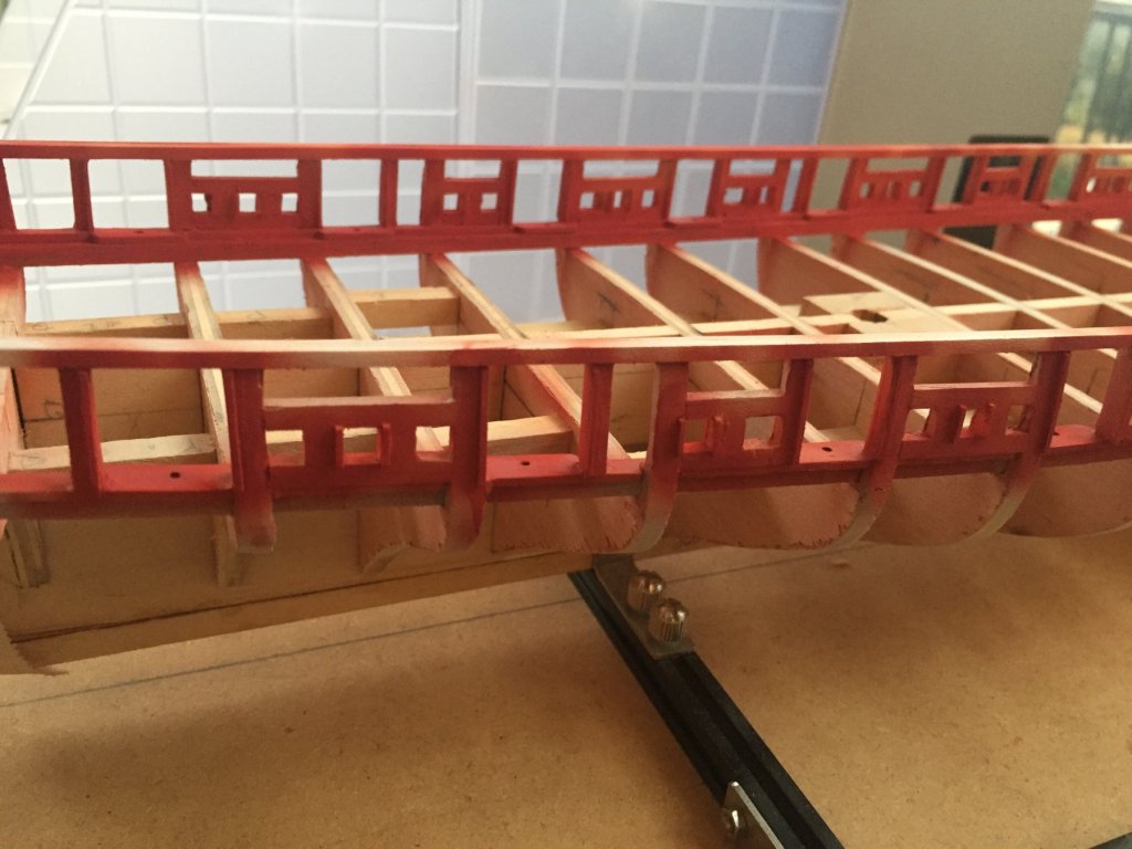
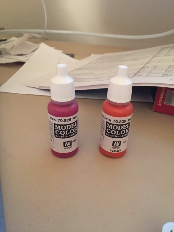
Next, i've framed the supports for the top rail. I found that using multiple thinner pieces of stock allowed for a nicer curve along the bow. No steam bending necessary when using thinner stock as well. Sadly, I failed to capture any photos of the laborious process of framing the gun ports. I also used the same technique as xken of using 1/32" square stock to mimic the inner surface of the gun ports and sweeps. Now onto the body work. I sprayed 2 coats of the Vallejo grey urethane primer with my airbrush and sanded between coats using 400 grit 3M ultra flexible . Additionally, I used the bondo spot putty on the inner side of the gun ports to even the surface and hopefully give the appearance of a single board through the full width. I attempted to color match the red from various photos and settled on the following: 1. 5 parts Vellejo red 2. 6 parts Vellejo amaranth red 3. 1 part flow improver 4. 3 parts thinner First coat is applied, I'll sand then shoot another 1-2 then apply a matte varnish (again, another fantastic xken tip).
.thumb.png.a8cca26ae5d0712e0e1b60fc40aa27ef.png)
.thumb.png.6d6350746dffc0412bca089710262af7.png)
.thumb.png.61bdf7adb08684e493193cfd40e632da.png)
.thumb.png.c30265f9e619eb8f382cd2f9c8be0699.png)

- 18 replies
-
- 3
-
-
- niagara
- model shipways
- (and 1 more)
-
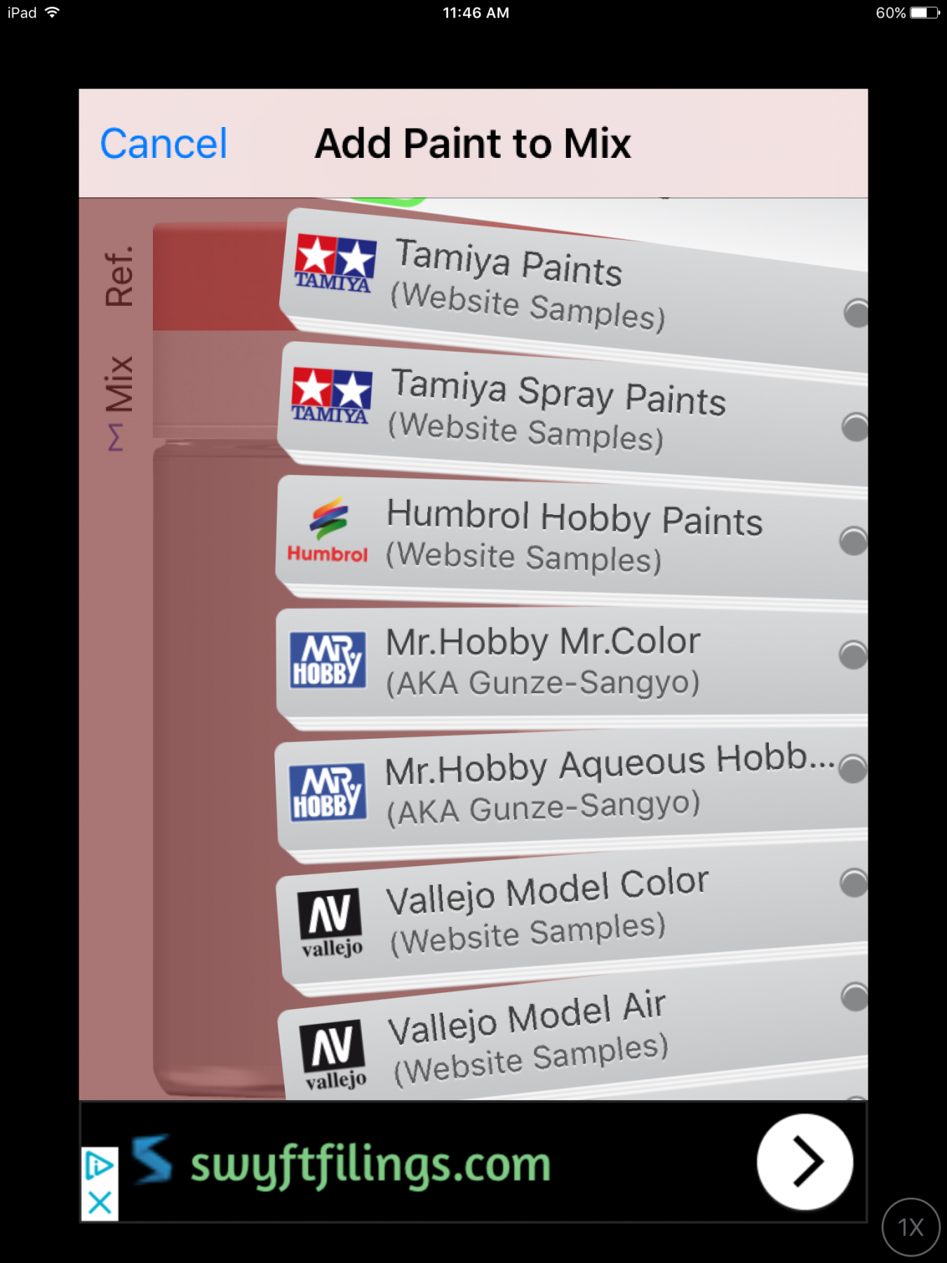
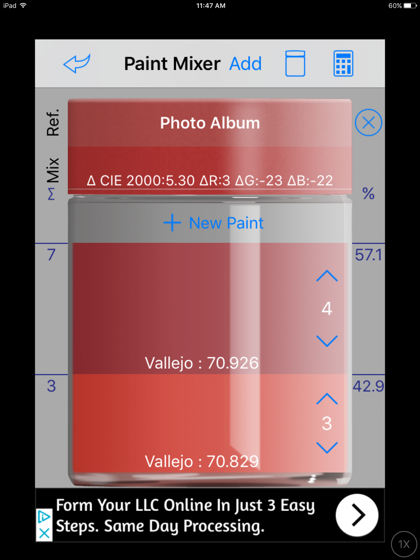
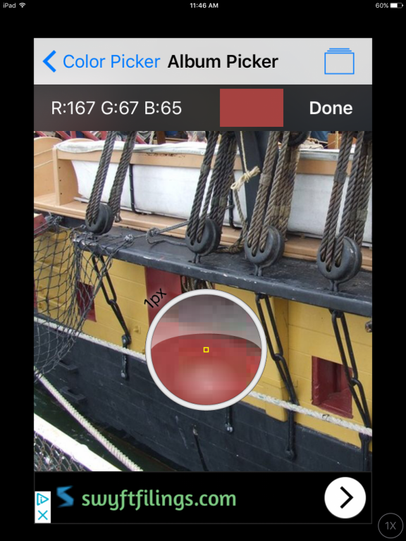
I found this very useful app for color matching photos to model paints. It has all of the major paint brands and will calculate blends based off of their published swatches. While not a foolproof technique, it seems like a decent baseline for approximate matching. http://www.id6.ch/id6_WebSite_en/iModelKit_v2.html


-
Stevenson's ER32 Collet Blocks
Ben752 replied to KeithAug's topic in Modeling tools and Workshop Equipment
I agree, they are very useful tools. Sherline also sells some, albeit smaller. Their square block is actually an octagon. I plan to get a set to mill the octagonal mast sections on my US Brig Niagra. http://sherline.com/product/2045-index-block-set/ -
How serious do you get about dust protection
Ben752 replied to bigcreekdad's topic in Modeling tools and Workshop Equipment
I use a small vacuum when working and keep a HEPA air cleaner running continuously (it's pretty quiet on the lowest setting, still tolerable on the higher ones). Even this tiny air purifier has helped quite a bit, however I've yet to graduate to any significant power tools.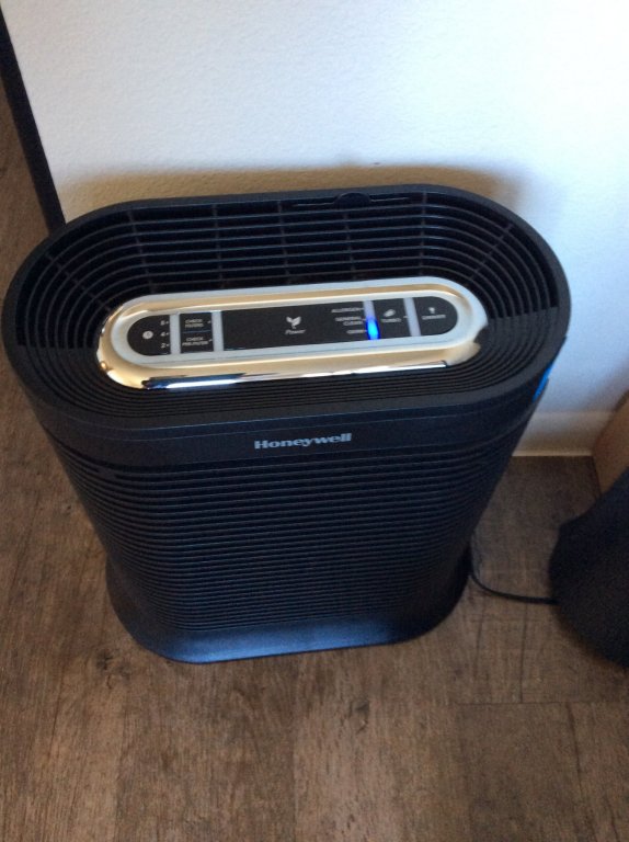
-
Yea, 30-40 thou is way off! One thing I found on my manual Sherline, is to check the spacing between the lead screw bracket on the slide and the hand wheel (I'm assuming this can still happen with how the stepper attaches). I had a gap on mine that was contributing a fair amount of backlash. Fixing it was as simple as adjusting loosening the set screw and pushing the hand wheel flush and tightening again. If the machine is really worn, the brass nuts inside of the slides are replaceable as well but it's a more involved process. I'd try replacing the brass anti-backlash nuts first. When I first received my machine, the prior owner had really tightened the gibs and it was causing the anti-backlash nut to not do its job effectively. Tapping them loose and lubricating/cleaning them appropriately was all I needed. I probably sound like a broken record but try Fusion 360, it's free for hobbyists. I find the parametric approach makes the most sense to me.
-
I agree on tracing if you're working off of scans. It's pretty easy to do this in Fusion 360 using "Attach Canvas" then tracing using a spline then use mirror to ensure symmetry. Then extrude and you have an STL. One thing I found when using attach canvas is it can be tricky to calibrate it accurately. Through some trial and error I discovered one pixel in an image is represented as 1/2048 of an inch. This might be useful if you want adjust the scaling factor manually.
-
I ended up buying a tool roll for all my files so they don't bang together in drawers, though finding one in the right size was actually pretty hard (only the same poor quality Chinese ones). I found some on Etsy, and hand made in Montana too. https://www.etsy.com/listing/241214316/handmade-tan-canvas-paintbrush?ref=related-5 The quality is great and I was happy to spend the extra to support a small business. They also will make custom size ones for not much more.
-
What software are you using? I'm debating converting my Sherline to CNC or buying something like a Shapeoko or Nomad from http://carbide3d.com/. I think the potential for using CNC mills is huge for creating high quality parts but modeling and building the tool paths is a skill just like any other.
-
Looks great! Machinist tool boxes work fantastic as well....but they can get a bit expensive.
-
Desktop CNC Router, Engraver, Mill
Ben752 replied to pompey2's topic in Modeling tools and Workshop Equipment
The control software may be windows only but you usually can interface other CAM software like Fusion 360 you do most of the work on your Mac and use Windows to run the program. One option is to use virtualization software from your mac to run Windows. We we use Oracle VirtualBox at work as it's free and open source. See http://www.oracle.com/technetwork/server-storage/virtualbox/overview/index.html. There are good commercial software options as well (Parallels, VMWare Fusion) but virtualbox has been good enough for my uses. Microsoft offers free downloadable images of Windows for testing browsers they just expire in 90 days. https://developer.microsoft.com/en-us/microsoft-edge/tools/vms/ Another option is to use Boot Camp that is built into OSX that lets you run Windows by rebooting. -
Thanks! I tried to take my time and it seemed to pay off.
- 18 replies
-
- 1
-
-
- niagara
- model shipways
- (and 1 more)
-
Desktop CNC Router, Engraver, Mill
Ben752 replied to pompey2's topic in Modeling tools and Workshop Equipment
Very interesting, I've been thinking about using this approach on my next build. Right now i'm considering a Shapeoko 3 as a CNC router, a 4th access should surely be nice but seems like a good start. Most use a Dewalt trim router with the setup but there are quite a few options for spindles if you're more of a shop build kinda person. -
I found a good source of carronade and long gun information in this book: https://www.amazon.com/Arming-Fleet-U-S-Ordnance-Muzzle-Loading/dp/0870210076/ref=sr_1_2?ie=UTF8&qid=1505675943&sr=8-2&keywords=arming+the+fleet. It's not limited to post 1812 weaponry and contains numerous drawings, details on carriages, rigging, etc.
-
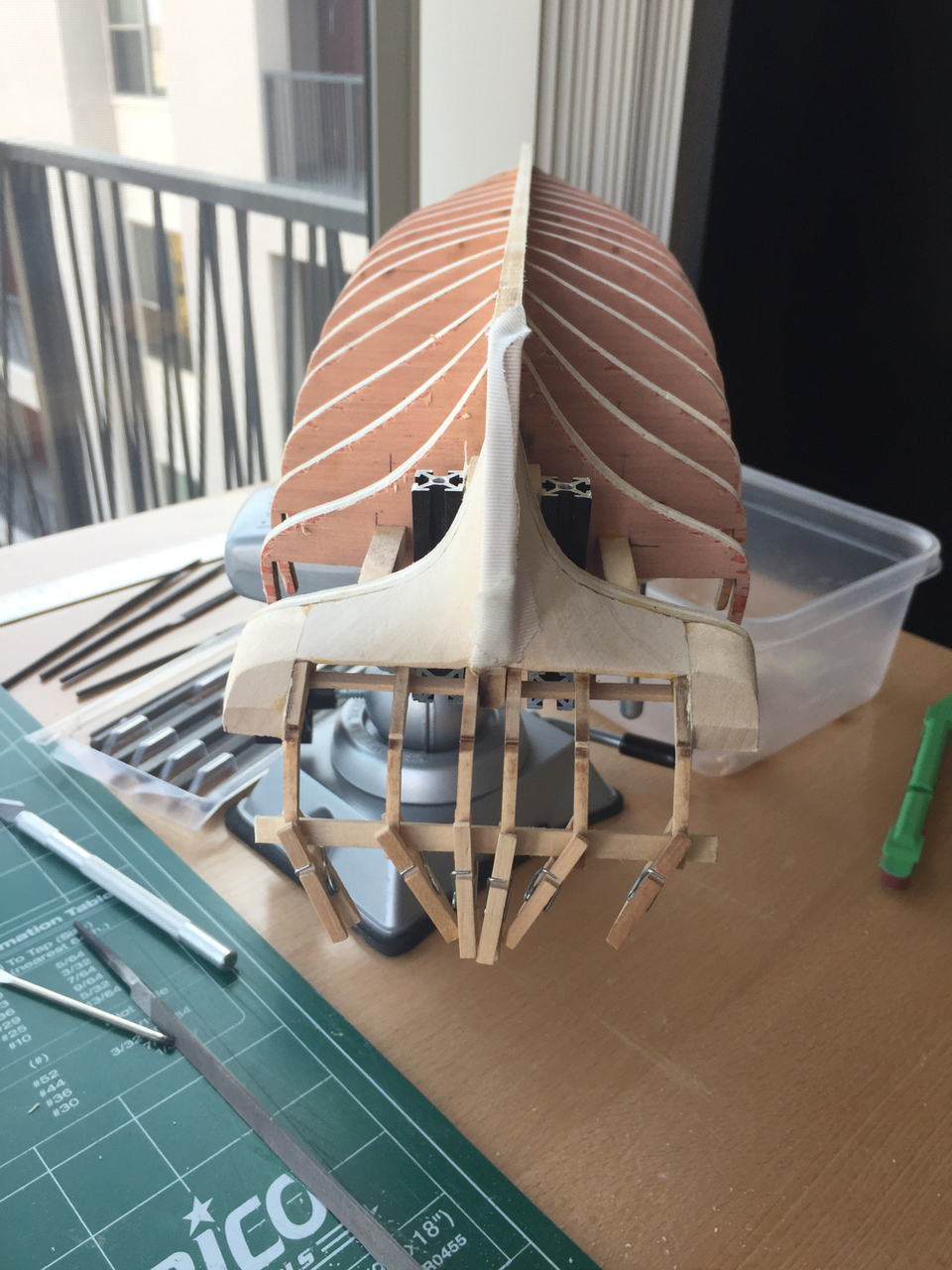
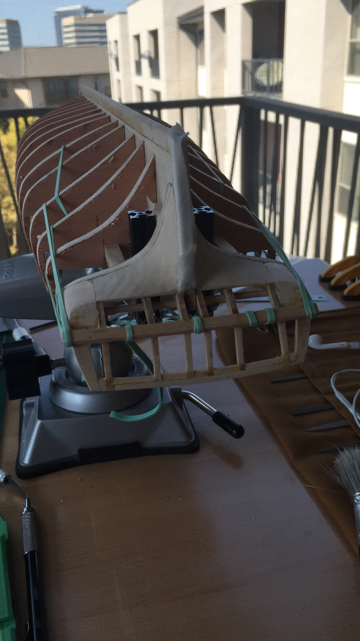
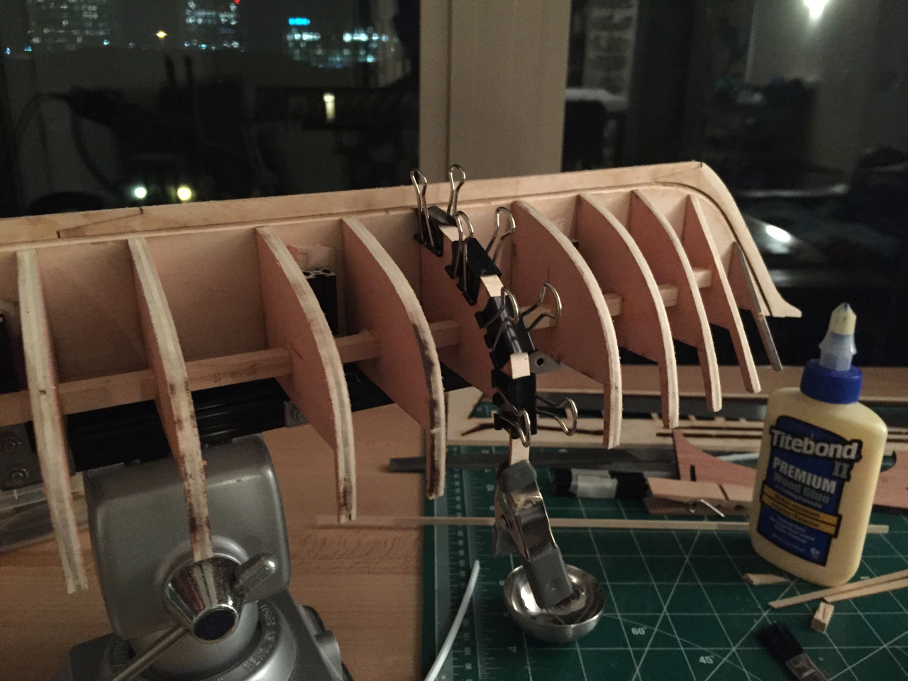
Now it's onto framing the transom and stern filler blocks. This took a bit of time as there is quite a bit going on. The horn timbers break if you stare at them incorrectly, luckily it happened only once. I found it easiest to align the timbers and use a scrap blank and some mini cloths pins to keep them in place while the glue sets. After I glued in the timbers I realized the profile was off a bit (the middle timbers were too low vs the outer timers). So I ended up adding 3/32 square stock on top of the stiffeners to align to the tops of the outer timbers. This ended up creating a nice arc much closer to the plans. I might have a bit of trouble with the gun ports but the extra framing will be hidden. Next is adding the arch board. I found rubber bands were the easiest to get the correct force along the angle as there wasn't a place to really clamp onto. I ended up using epoxy to hold the arch in place as the timber is relatively thick and has a slight arc.


- 18 replies
-
- 3
-
-
- niagara
- model shipways
- (and 1 more)
-
I suspect most users of these are for fine metalworking however the coarser cuts are quite useful for wood and other soft materials such as plastic. I've had better luck getting better quality tools from jeweler supply companies over hobby shops. I think part of the wood/metal file distinction is that it seems many vendors often categorize rasps as files. Lee Valley does sell a tool called a milled tooth file that look pretty interesting as they function more like a saw instead of an abrasive. I could totally be wrong on this!
-
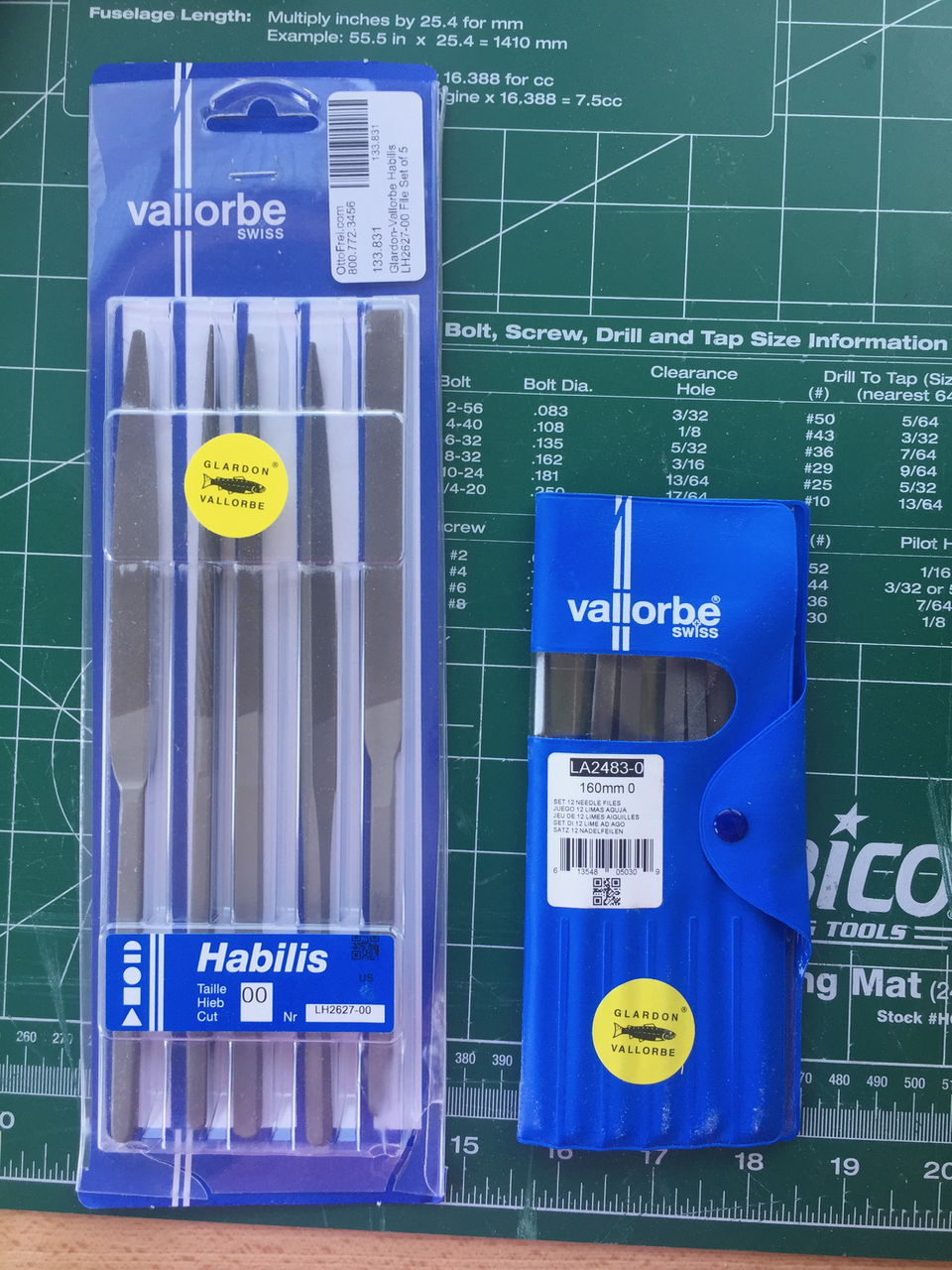
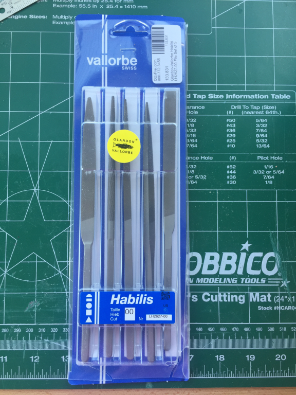
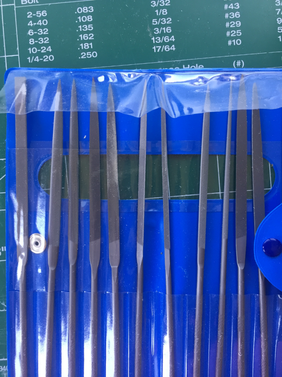
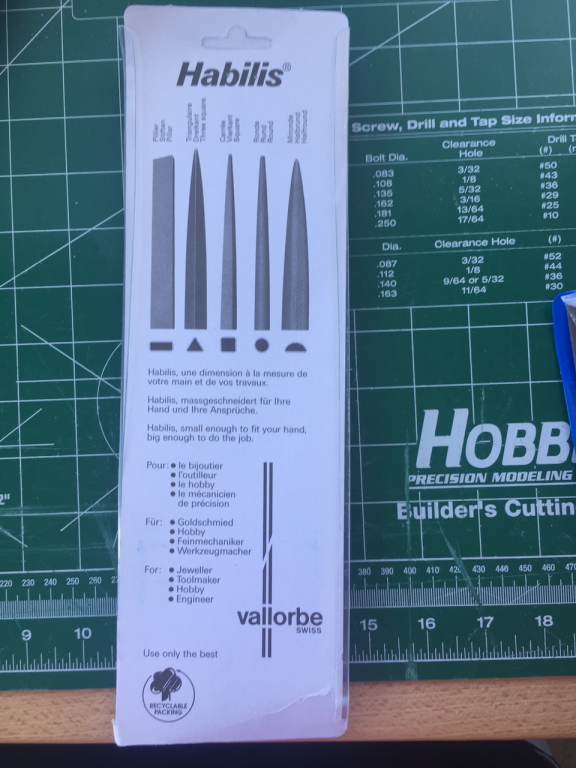
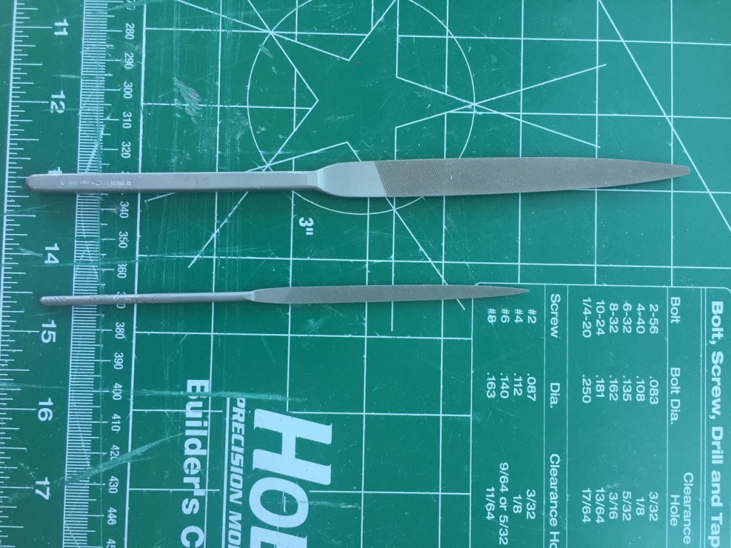
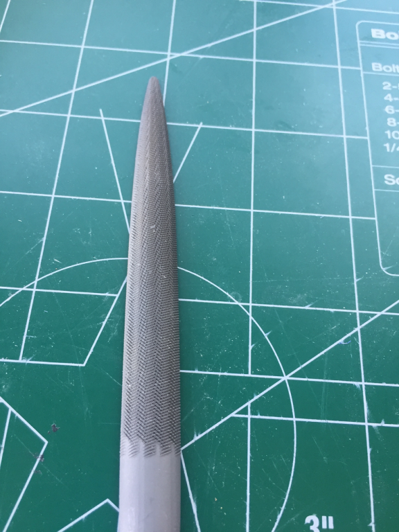
After buying a few sets of cheap import files that really tended to incite frustration followed by anger, I decided to purchase some new files (post-hoc). If if anyone is looking for upgrading files, I'm very happy with the following purchases. http://www.ottofrei.com/Habilis-Vallorbe-Files-Set-of-5 - Extra Coarse 00 * These are $67 but work excellent as roughing files and have a nice balanced feel and are designed for use without a handle. Basswood causes the files to not bite if too smooth it seems. The 00 Habilis grab nicely on basswood and the extra weight seems to aide in the cut. The 3-square works well in cutting slots, it fit horn timbers. * I've been using them for roughing work on filler blocks. These gave me some much needed tooling between a dremel and the cheapie diamond grid needle files, which turns out is something I desperately needed. * Highly recommended. A little pricey but given how much I use them now. http://www.ottofrei.com/Glardon-Vallorbe-LA2483-Swiss-Made-Needle-File-Set-Of-Twelve-6-1-4-16-cm?custcol_of_xc_file_cut=1 - Course 0 * Very nice set of files. * I haven't used these much yet (i've only had them for a week) but I suspect they will be used very often as I progress through the build (and take on more metalworking projects). * $84-93


-
Sherline model 4400DRO Lathe
Ben752 replied to J T Lombard's topic in Modeling tools and Workshop Equipment
If you have interests in machining beyond ship building there are certainly some advantages with a larger machine but if it's just for model making then it probably covers all of what you would want. I have a small non-Sherline mill but after significant deliberation and work on a friend's machines I'm leaning towards getting a standard bench mill and lathe. You might luck out and find a Sherline on Craigslist, on eBay it seems the used prices are 60%+ of the retail prices. Tooling and accessories seem to be better deals. A couple of months ago, I missed a craigslist sale of a retired clock maker that was selling both machines with the DRO packages for a fantastic price. So they are out there. Also, take a look at their distributors list and call around to see what price they can offer since I think most will be drop shipping your order from Sherline. -
Sherline model 4400DRO Lathe
Ben752 replied to J T Lombard's topic in Modeling tools and Workshop Equipment
One reason to consider the DRO lathe is that Sherline sells a vertical milling column (one with the DRO sensor $190 3050-DRO/3053-DRO & one without $157 3050/3053) for their lathe that allows you to convert it to a mill (though with a reduction of the milling area). If you don't already have a mill it's a way to get into a full DRO setup without buying two machines as the display box supports 3-axis + the speed readout. But I agree, the DRO on a lathe is nice but definitely not required. With a mill, I would definitely get the DRO option. -
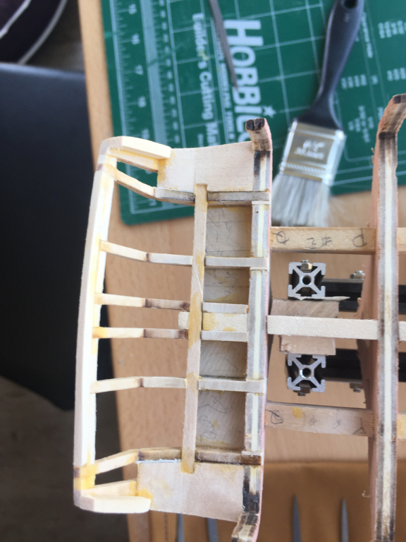
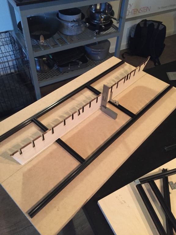
I've added a shim to M since the photo, and just checked N and it could use about 1/32 in some spots. I was a little unsure if I got too aggressive with the shaping. Hearing your comments about M & N is very useful. So far the building board seems to be working well. I'll see if I can put a half way decent drawing showing how it's put together if interesnted. The key components are: Base - 2 ft x 1 ft x 3/4 in MDF 2x 600mm Makerbeam - parallel and 100mm from the midline using the inside faces https://www.makerbeam.com/makerbeam-600mm-1p-black-makerbeam.html 2x 200mm Makerbeam - that act as the cross members https://www.makerbeam.com/makerbeam-200mm-8p-black-makerbeam.html Corner brackets to add stability between the beams 4x Corner brackets to act as clamp https://www.makerbeam.com/makerbeam-corner-brackets-12p.html I used M3 computer thumbscrews along with the Makerbeam T-slot nuts to allow for finer adjustment (https://www.makerbeam.com/makerbeam-t-slot-nuts-for-makerbeam-25p.html) The beams are held to the board via countersunk holes and M3 screws through the back into T-slot nuts on the underside of the beams. The hardest part was really just measuring it and ensuring accurate alignment along with the right depth of the counter sunk holes as the number of the threads on the T-slot nuts are very small so the margin of error is low.
- 18 replies
-
- 1
-
-
- niagara
- model shipways
- (and 1 more)
-
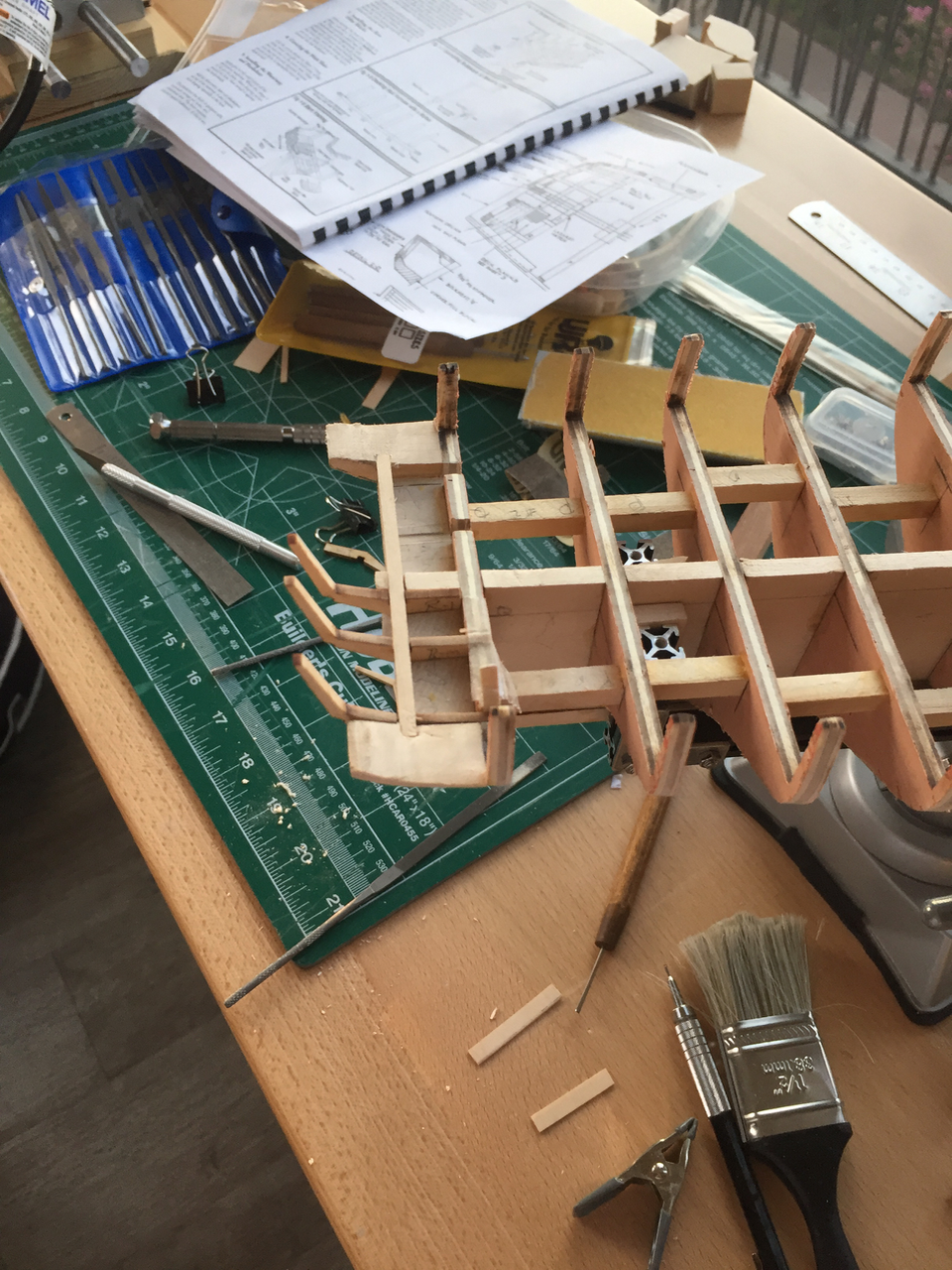
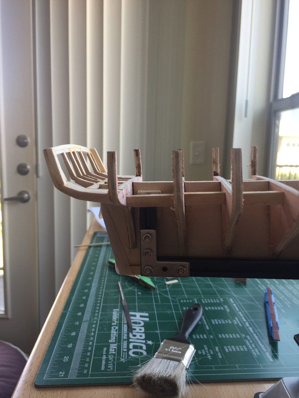
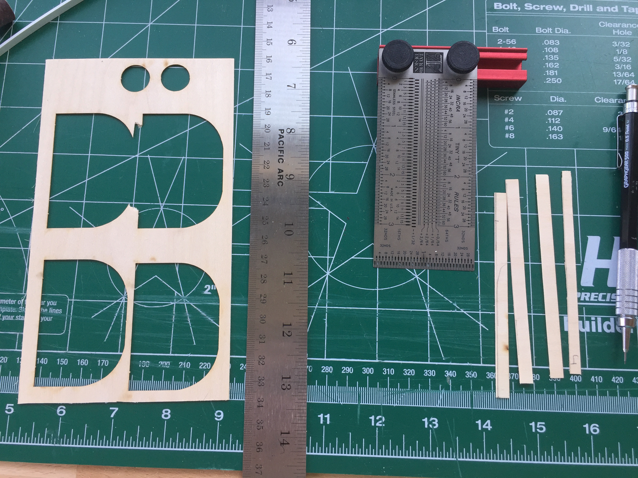
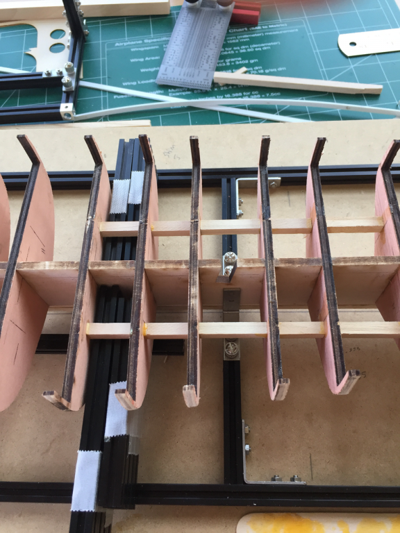
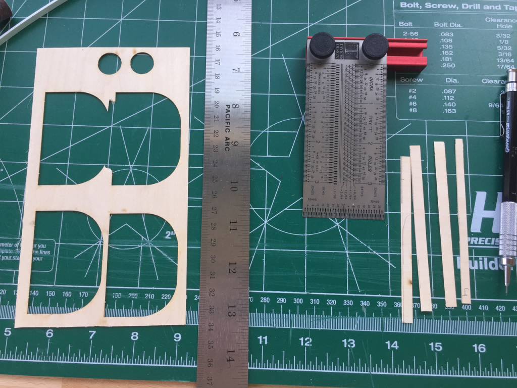
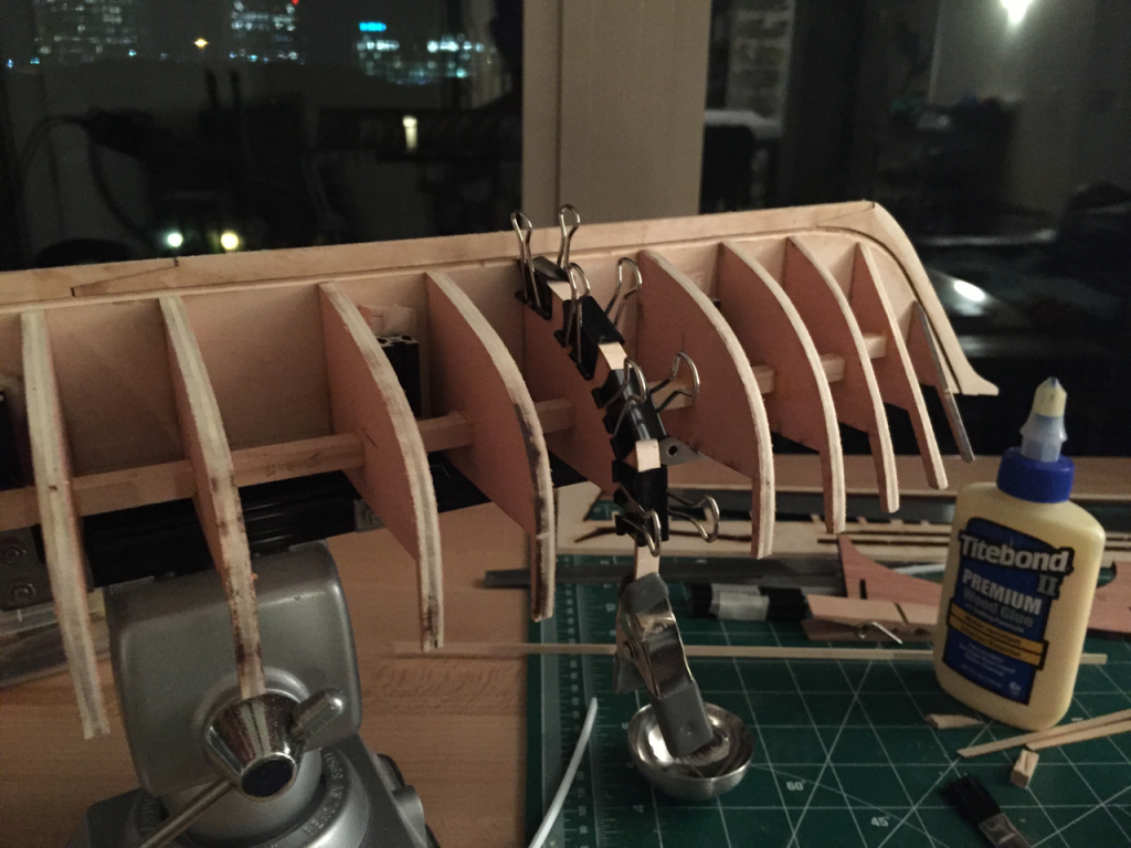
As I became fairing the hull and fitting battens it became obvious that struts would be useful in providing rigidity for the operation. I cut the struts from 1/4" by 1/4" square dowels I picked up a hobby store. I cut each piece about 20 thou under in hopes of preventing any self induced keel warp. That ended up working out pretty well, titebond seemed to pick up the gap nicely. I marked off either side of each bulkhead using my Incra ruler to mark the distance from the keel. For those don't have one of these, I highly recommend it. The holes in the ruler are cut precise for 0.5mm lead so you can precisely mark up to 1/64th. Next, I used stacks of Makerbeam as guage blocks to set the vertical hight of the strut and provide a resting surface while the glue set. A couple bulkheads were either the wrong size to begin with or I got a bit carried away with my Dremel during sanding. What I did to shim the couple bulkheads was cut strips of 1/32" basswood from some of the laser cut scrap. I cut them cross grain to maximize contact with the bulkhead when gluing. So far it seems to work pretty well. A little sanding with a block and the edge of the shim tapered nicely.
- 18 replies
-
- 3
-
-
- niagara
- model shipways
- (and 1 more)
-
Fusion 360 is excellent and they've made it free for hobbyists.
-
Thank you everyone for your encouraging words! I finally stopped putting off creating a build log, so I'm a bit further than the pictures show but I failed to take photos of some of the steps. I'll post more soon. Thanks again!
- 18 replies
-
- 1
-
-
- niagara
- model shipways
- (and 1 more)
-
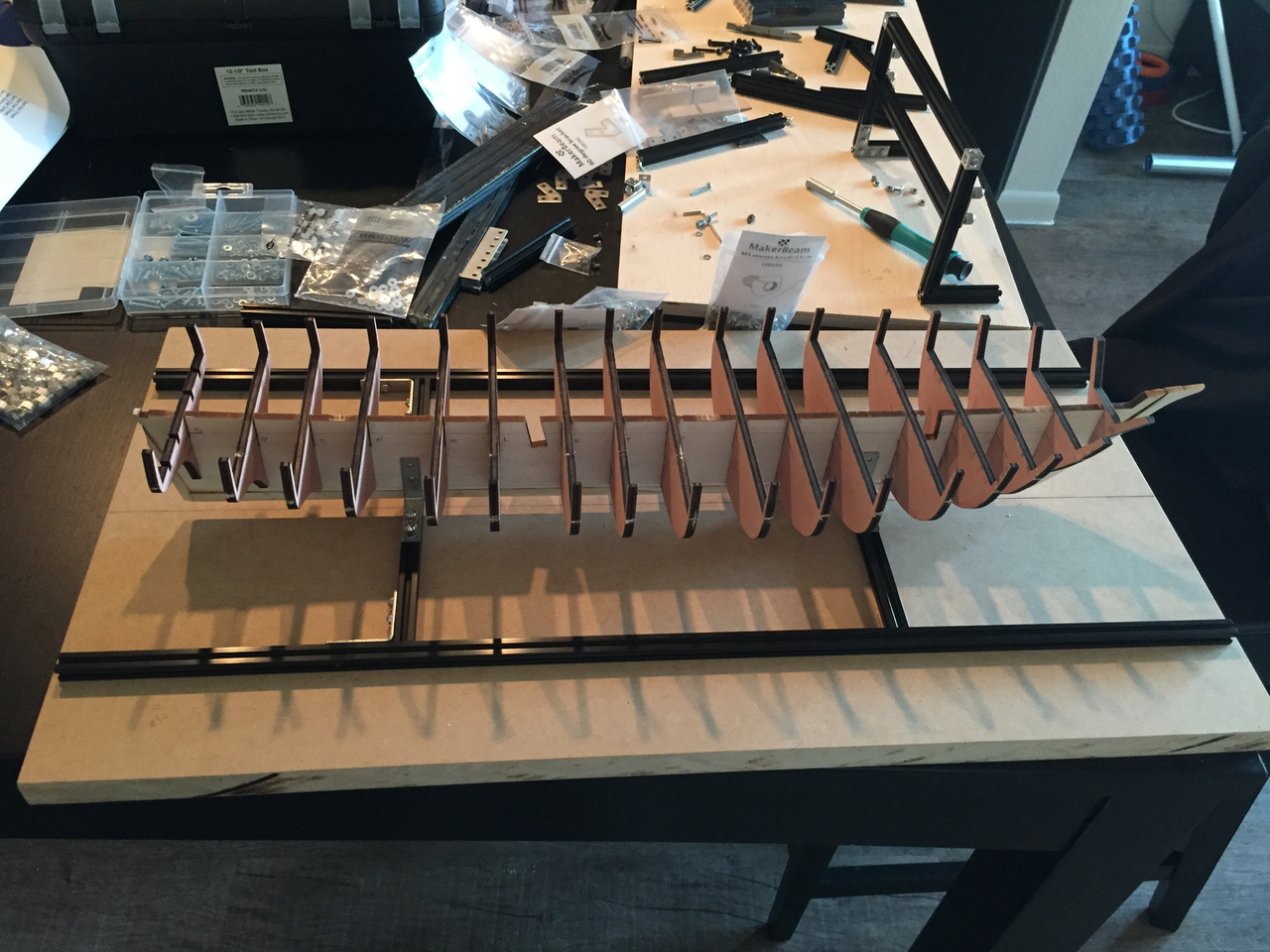
After doing a fair bit of research on MSW and thinking critically about my abilities, I've settled on the USS Niagara as my first wooden model ship. My experience with wooden models has been limited to RC planes and the tissue covered balsa variety. I must say, laster cut parts are significantly better than the stamped balsa variety! I began by constructing a building board out of 3/4" MDF. To hold the keel perpendicular to the board I designed a frame and clamping system out of Makerbeam (a small extruded aluminum t-slot profile with 4 faces) and attached it to the board via countersunk holes through the back of the board.

- 18 replies
-
- 8
-
-
- niagara
- model shipways
- (and 1 more)
.png.a822a1c7756421949a227a9325a3569e.png)
.png.7cc0ffcc46fa230d9f8f7ecfbc5e6e32.png)
.png.07708e8f220fbef9d410bbdd82344323.png)
.png.2c43257ff24a51add98cf07542d7e8b9.png)