HOLIDAY DONATION DRIVE - SUPPORT MSW - DO YOUR PART TO KEEP THIS GREAT FORUM GOING! (Only 69 donations so far out of 49,000 members - Can we at least get 100? C'mon guys!)
×

Zarkon
-
Posts
295 -
Joined
-
Last visited
Content Type
Profiles
Forums
Gallery
Events
Everything posted by Zarkon
-
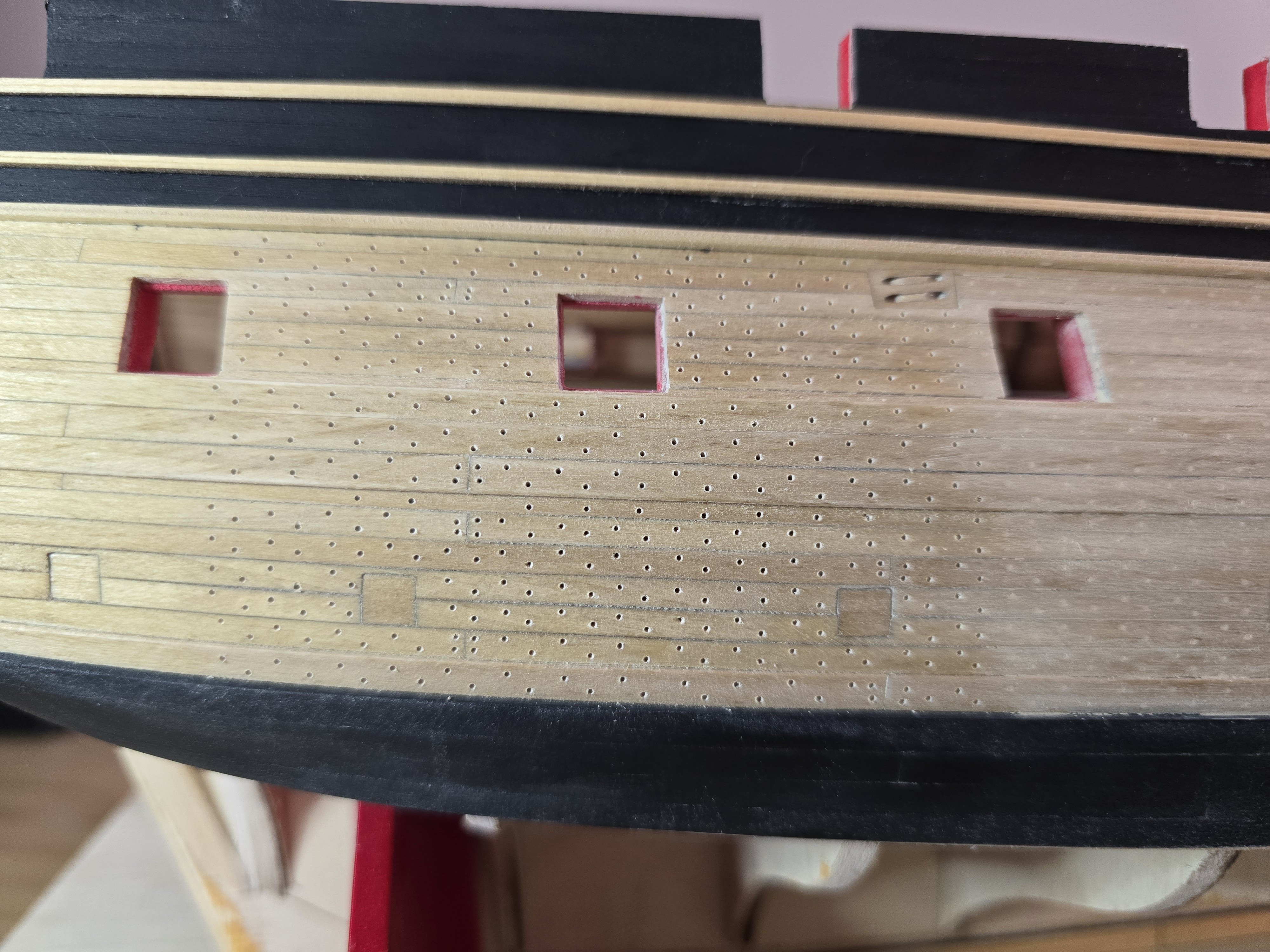
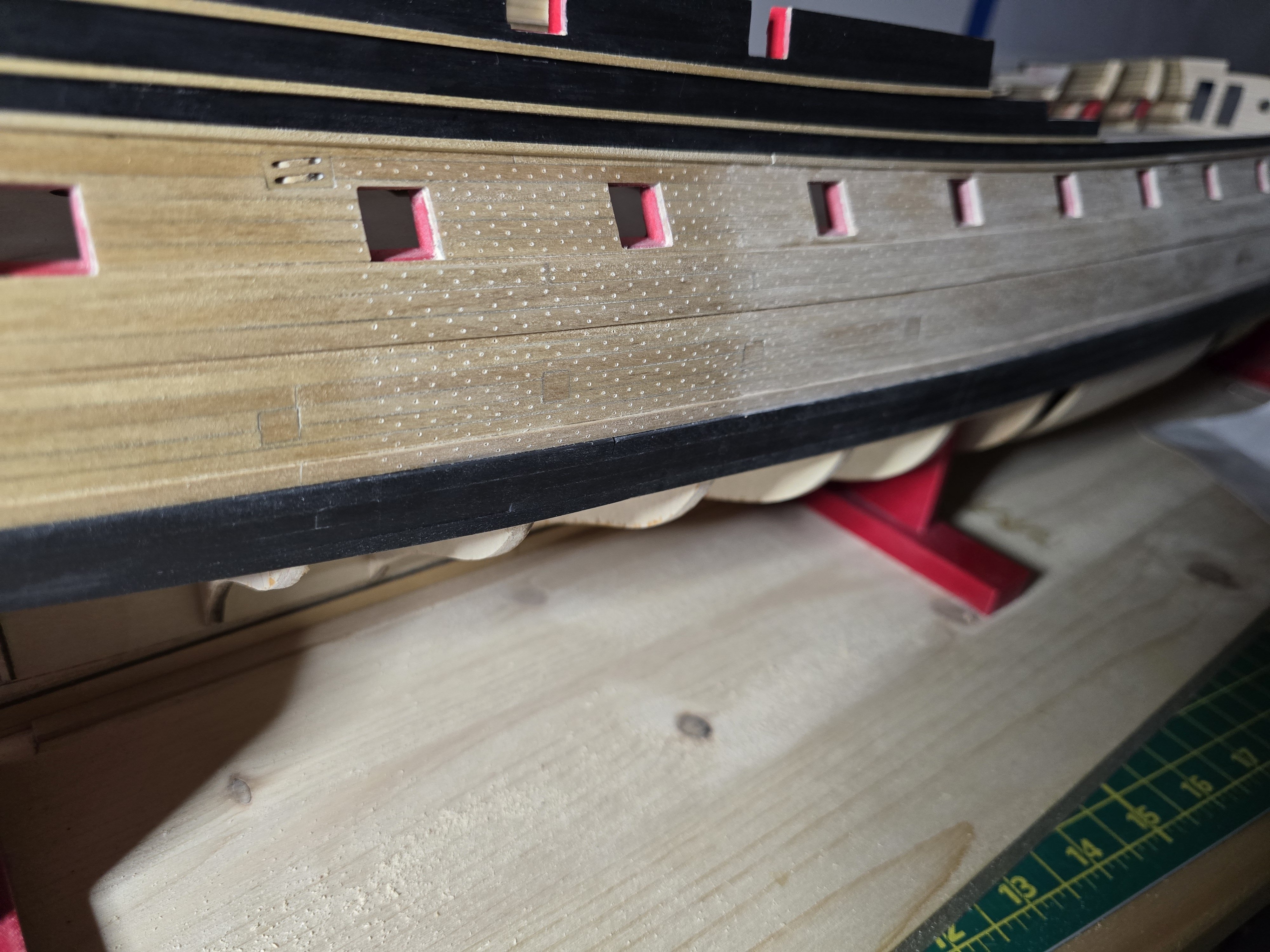
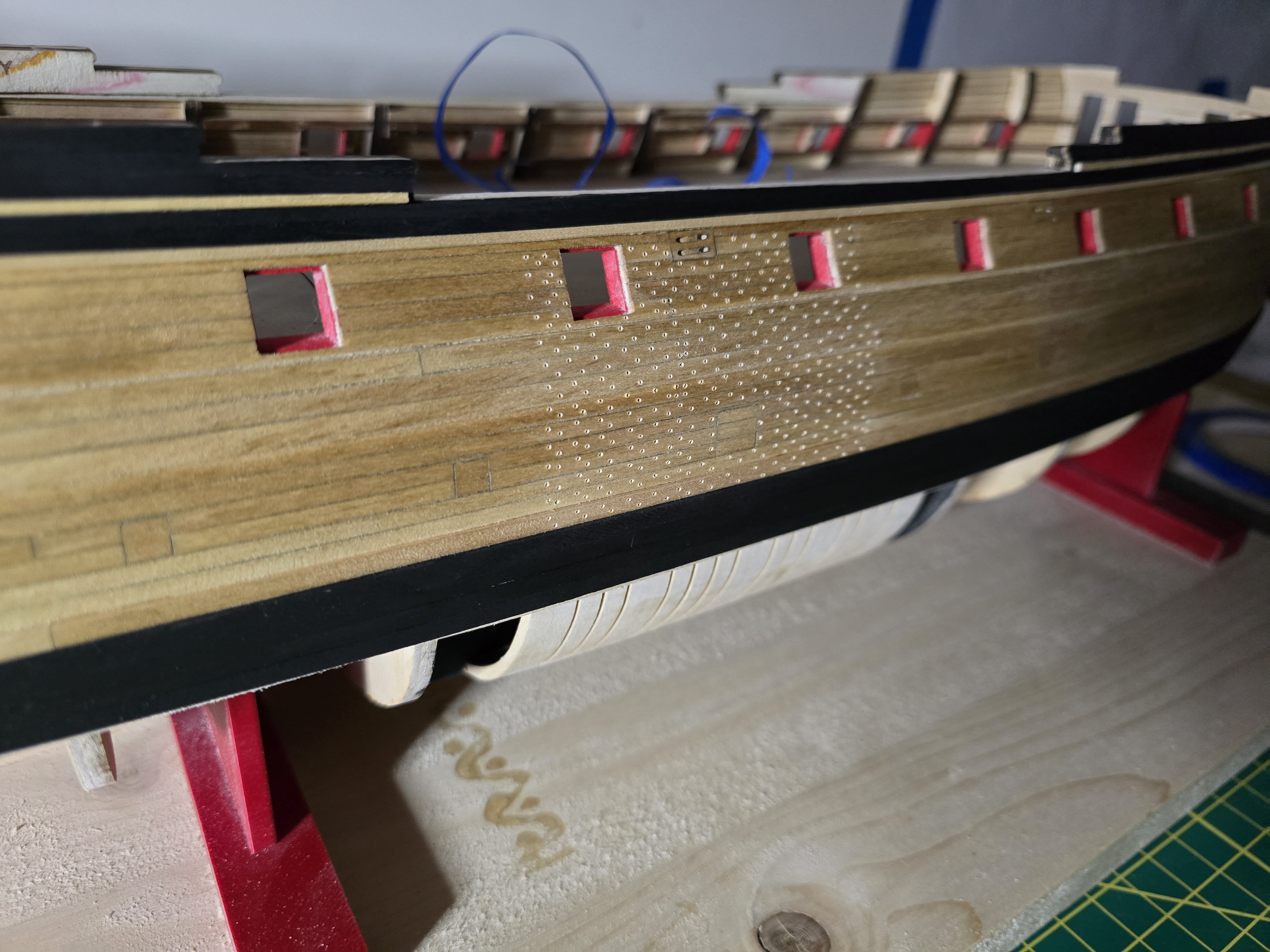
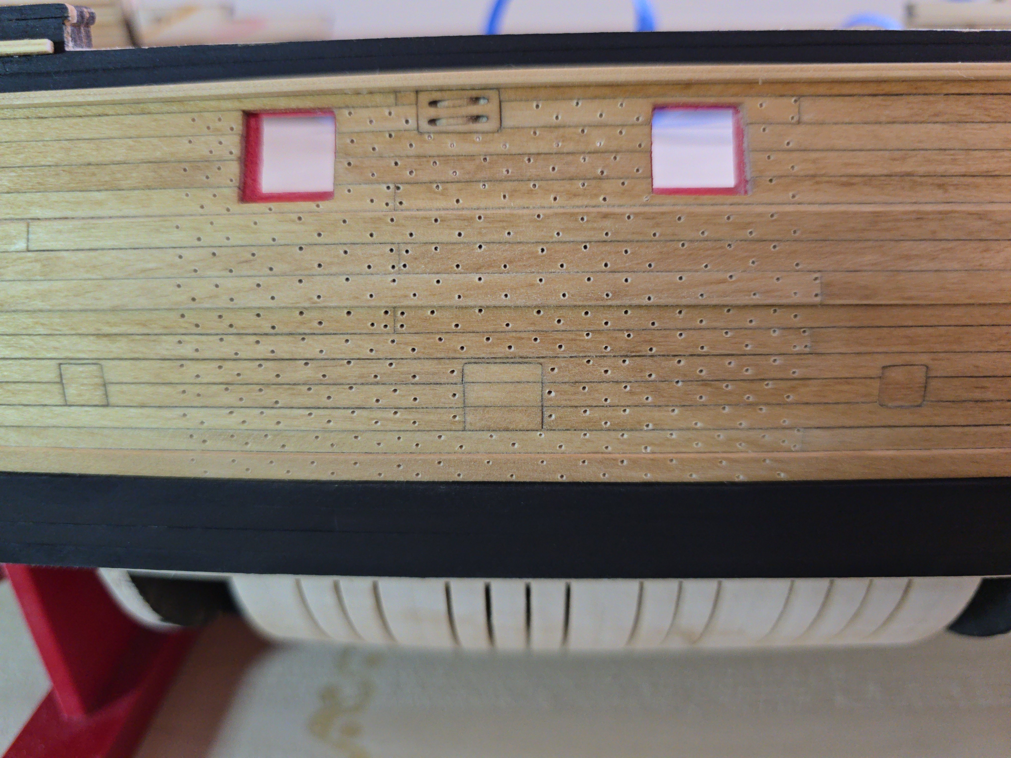
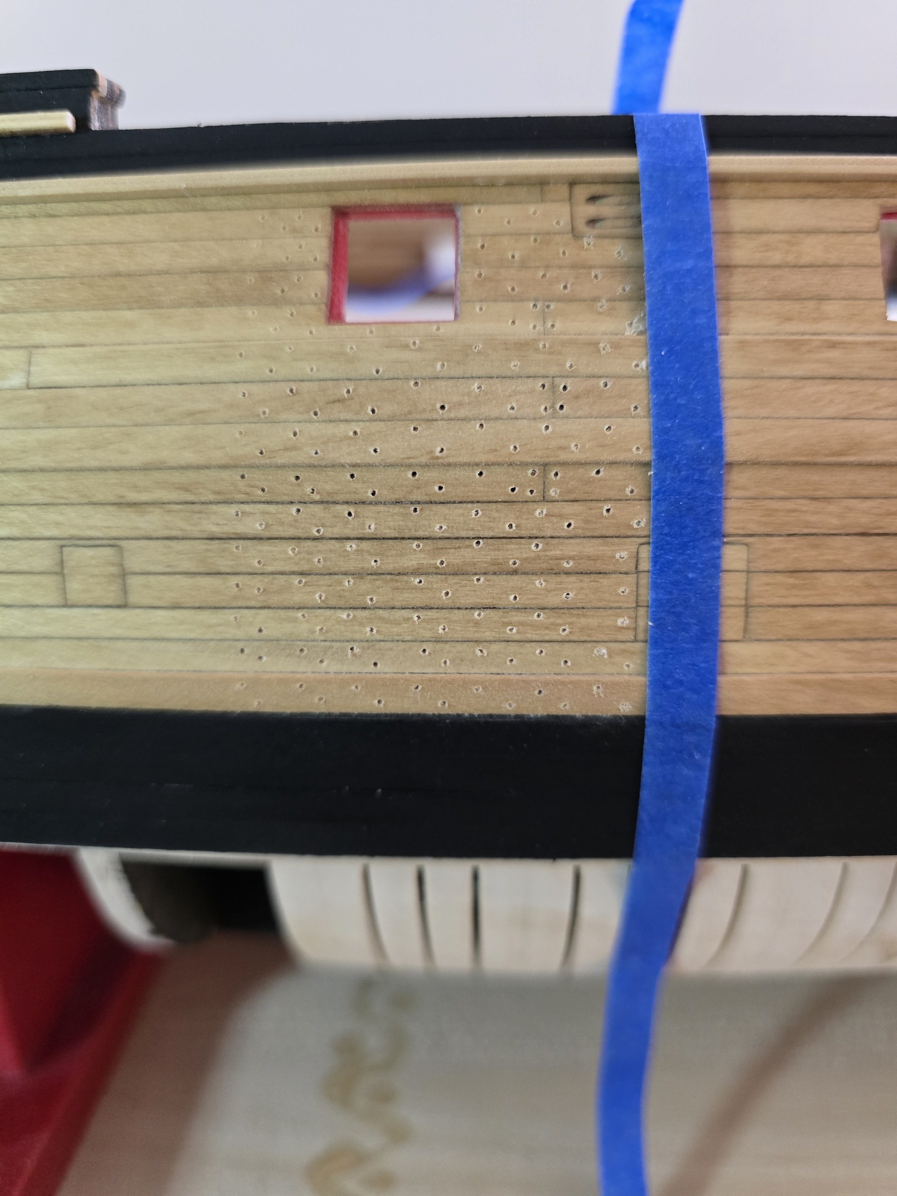
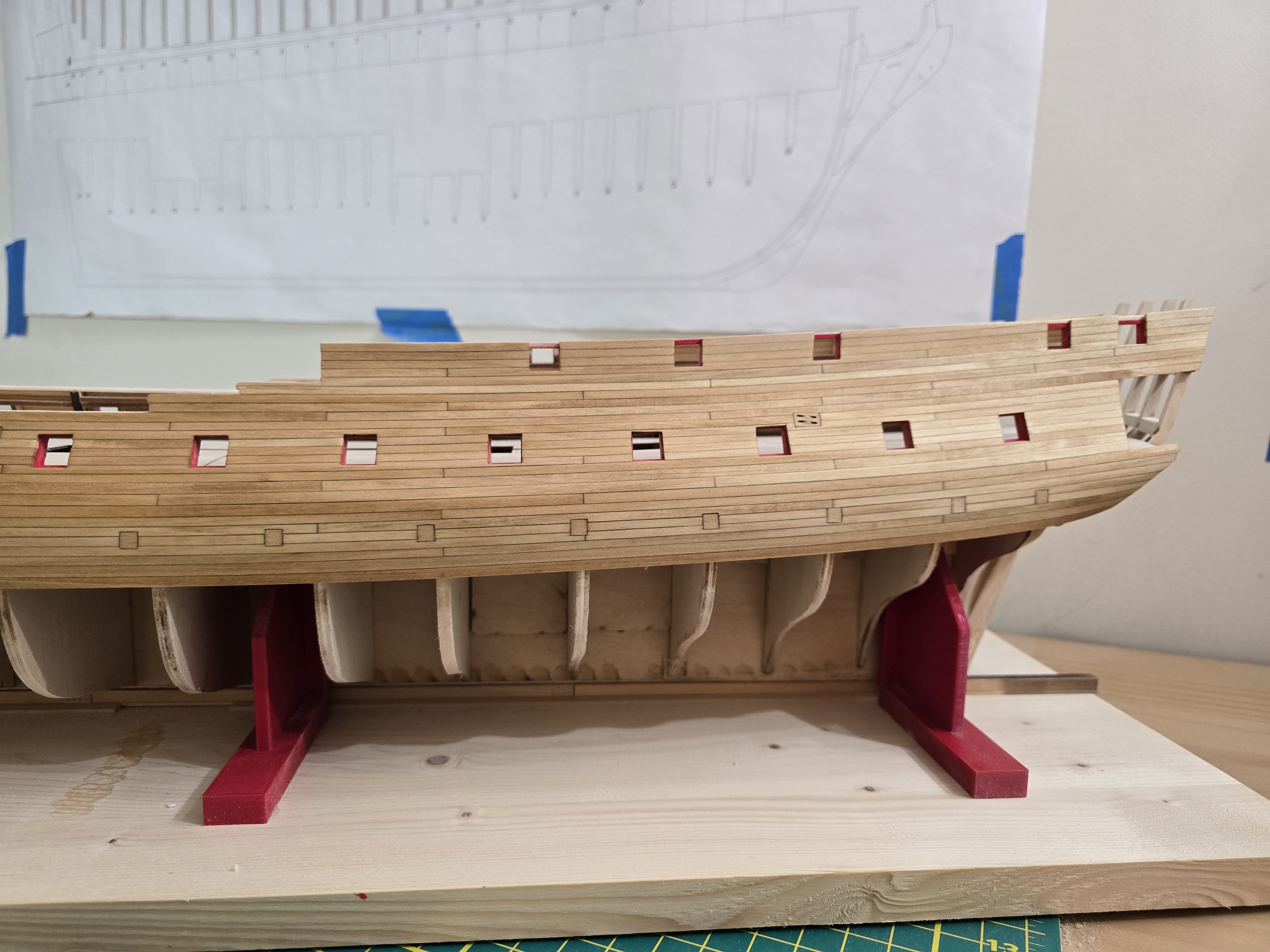
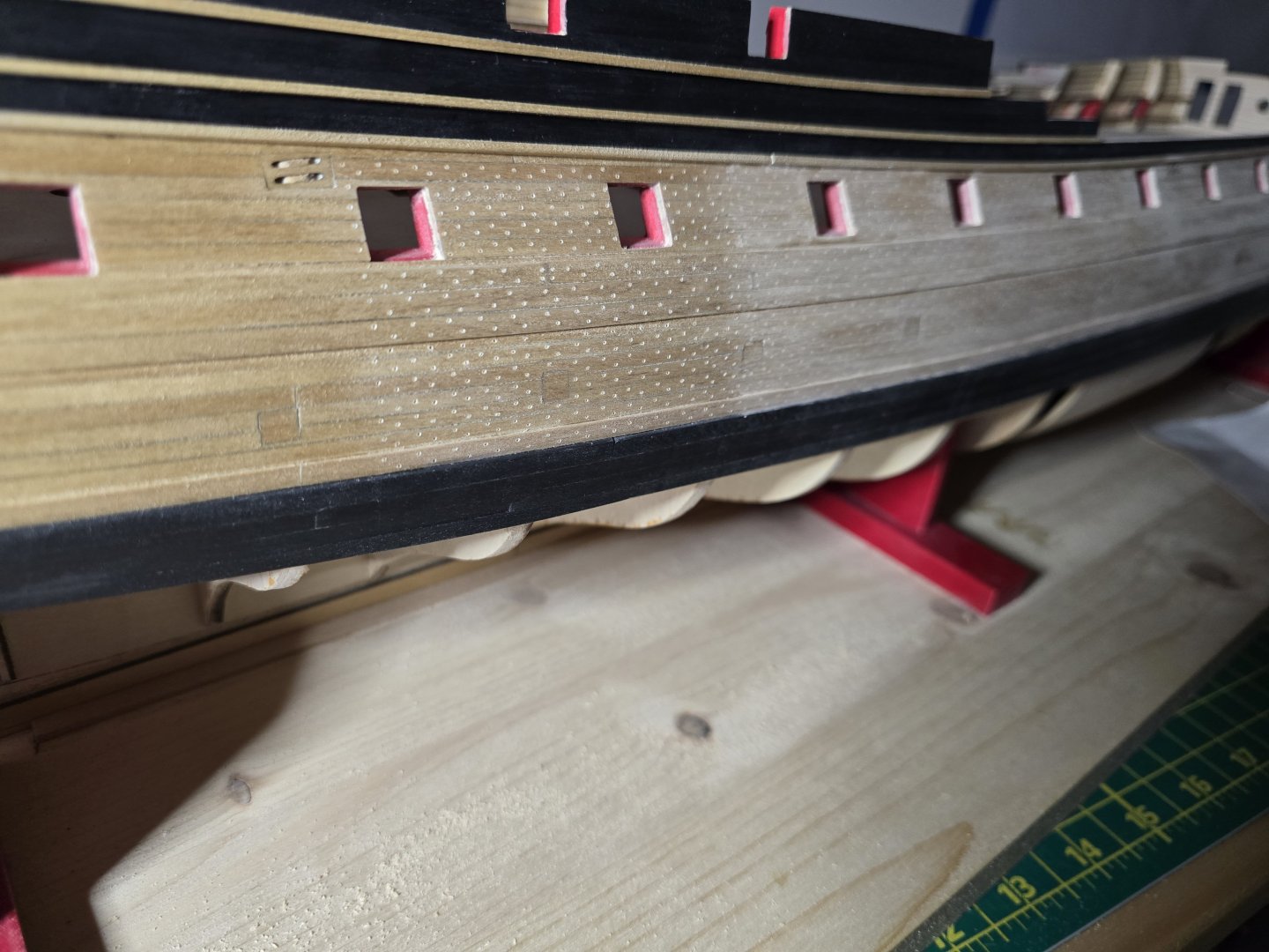
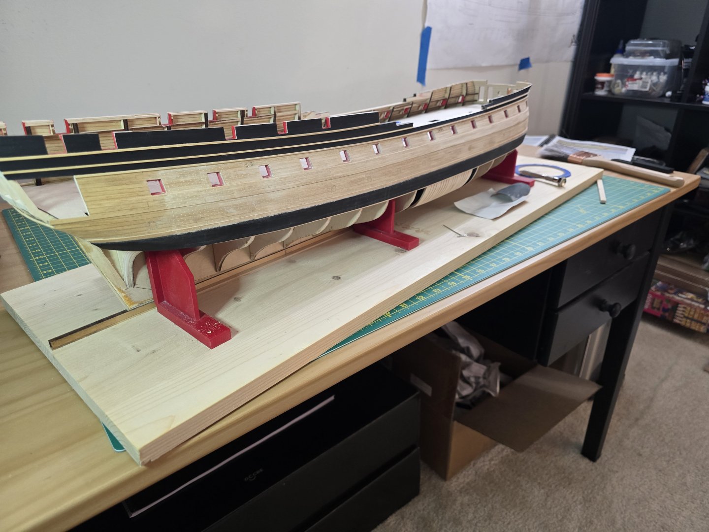
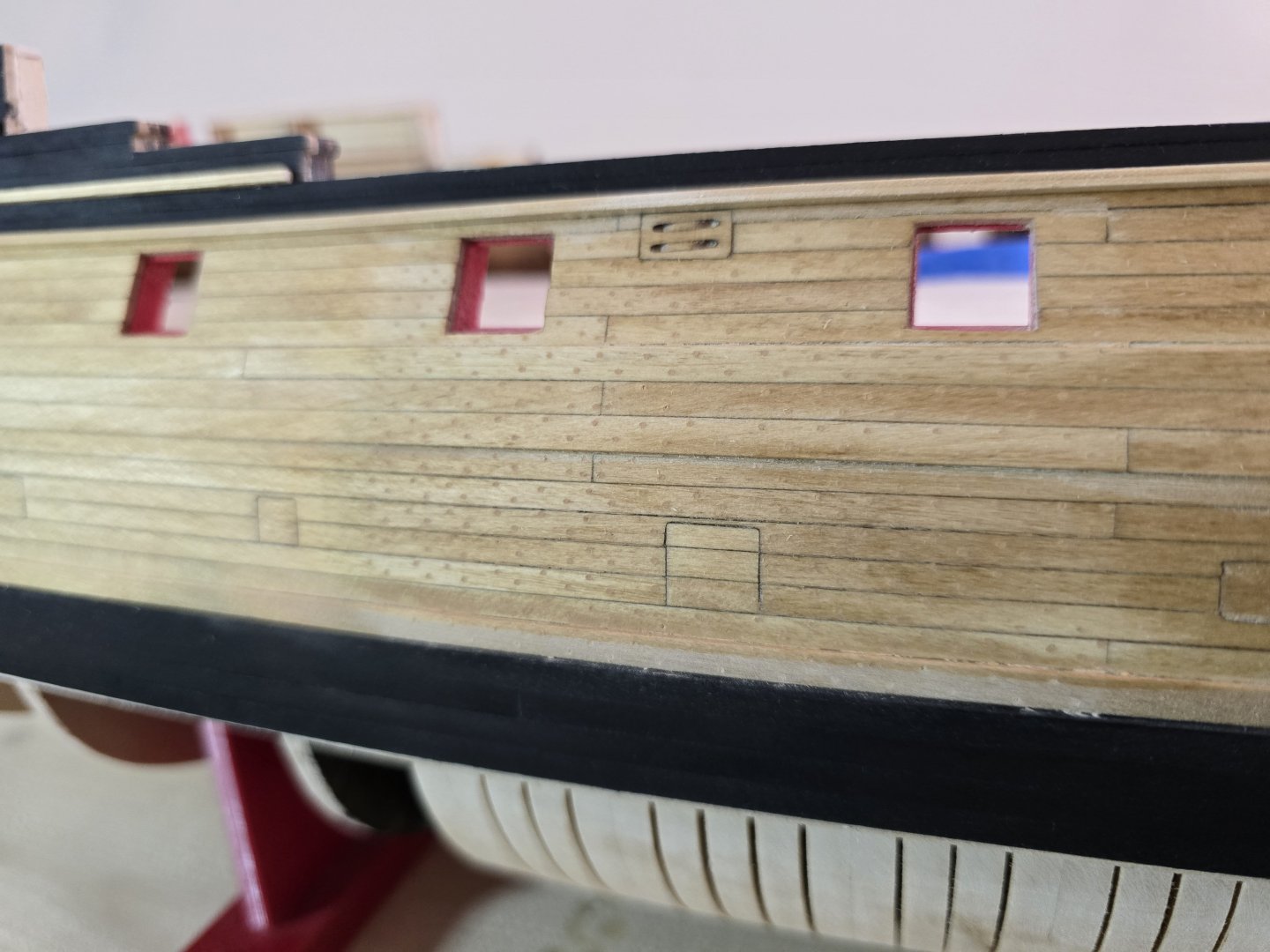
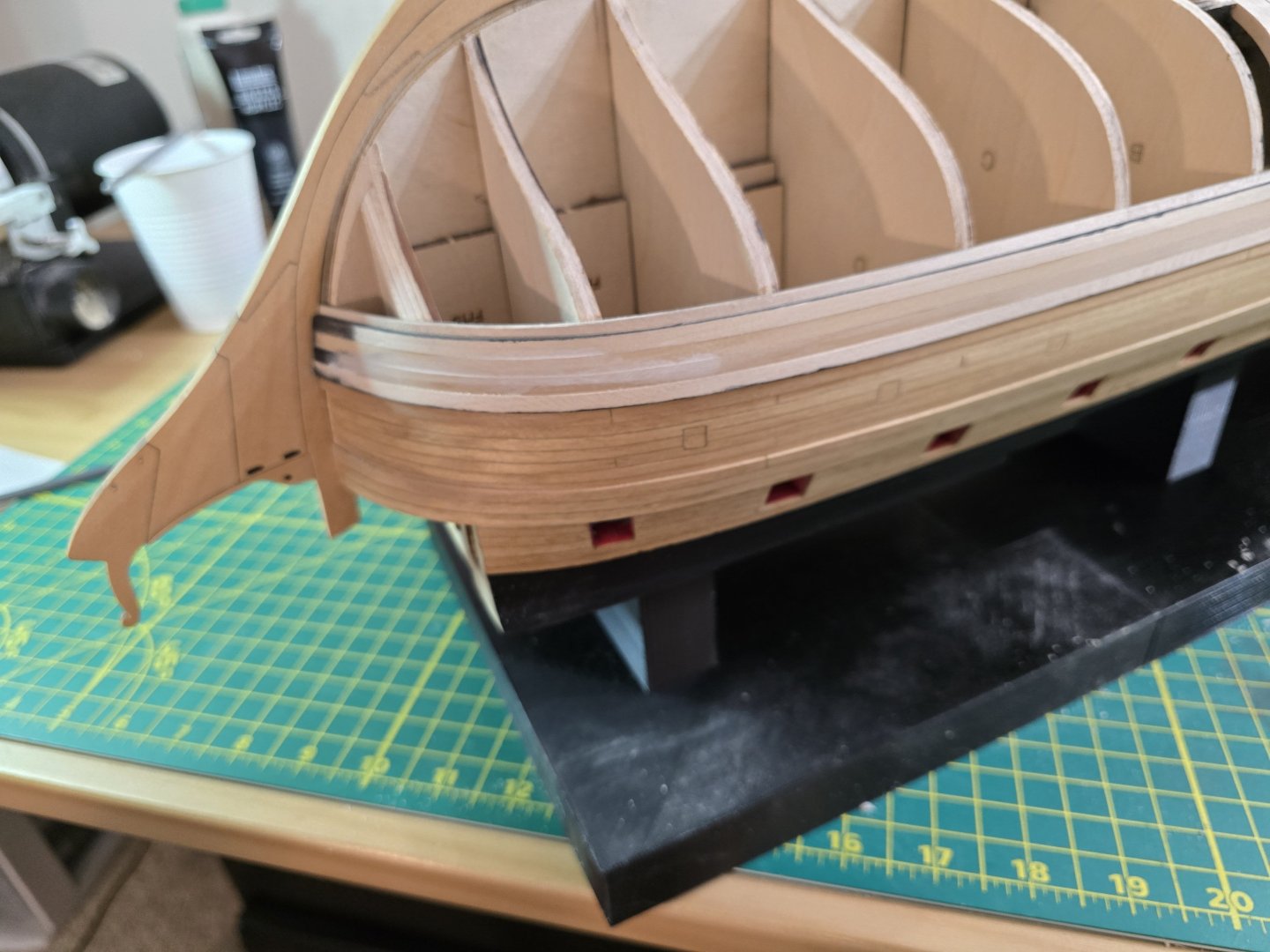
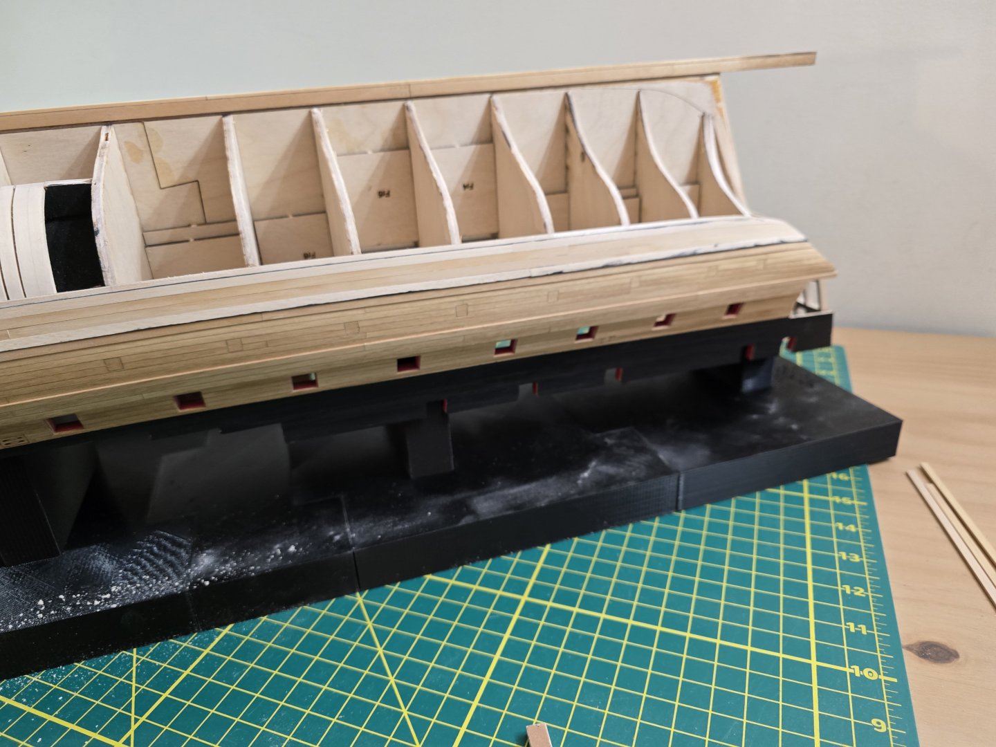
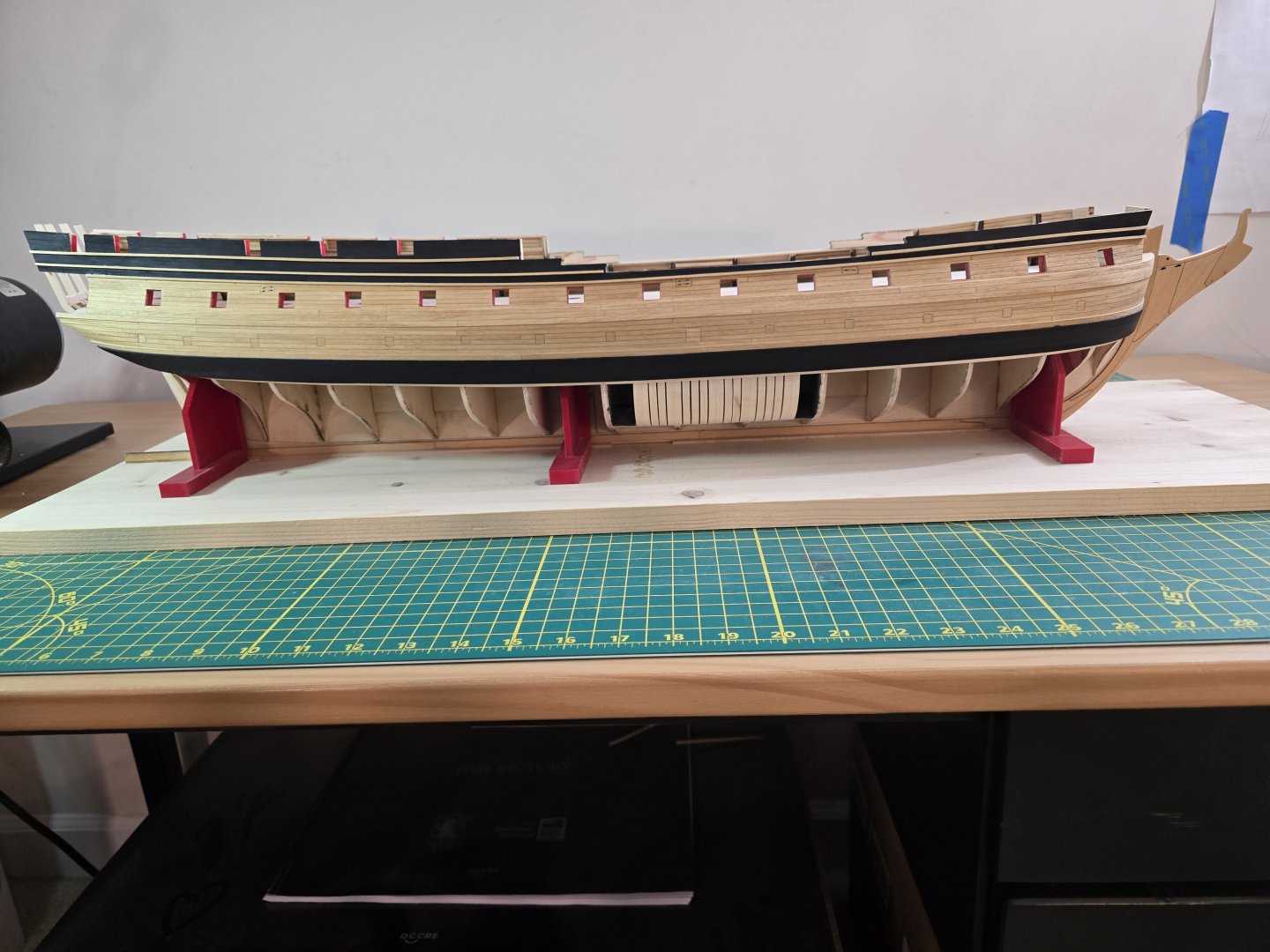
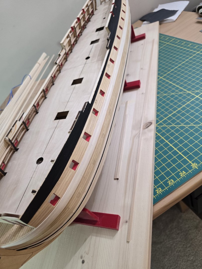
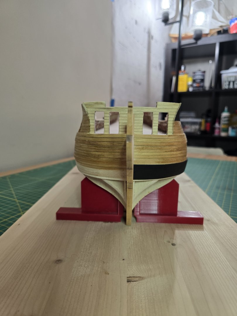
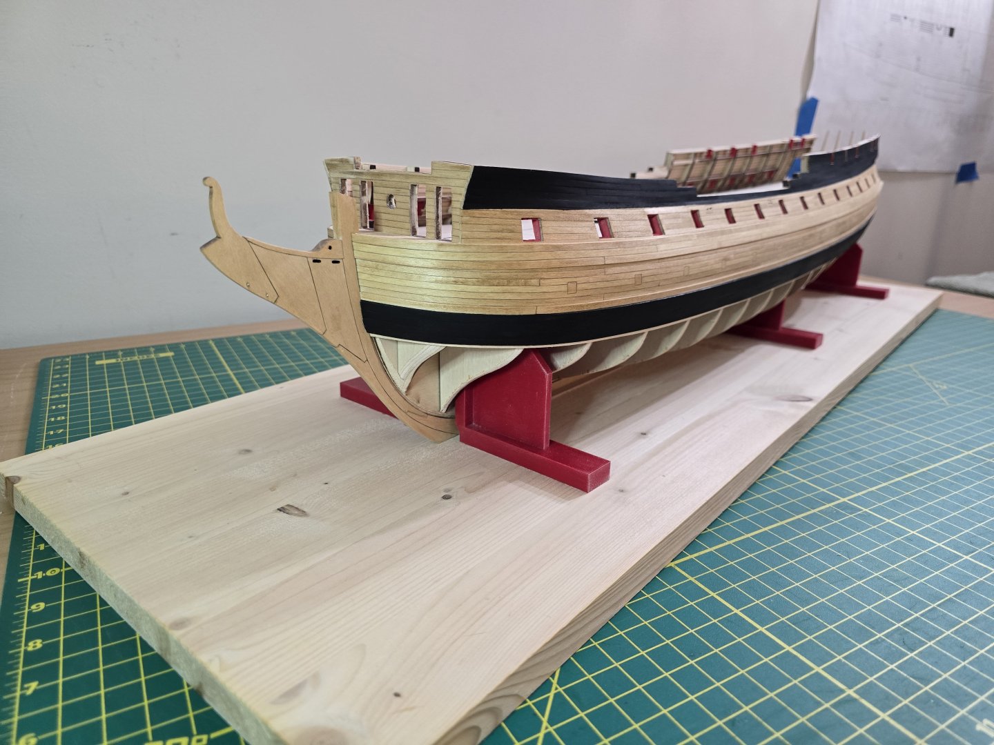
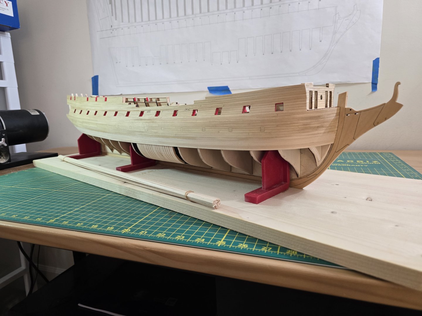
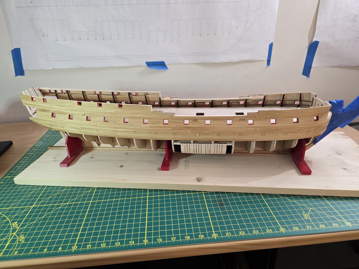
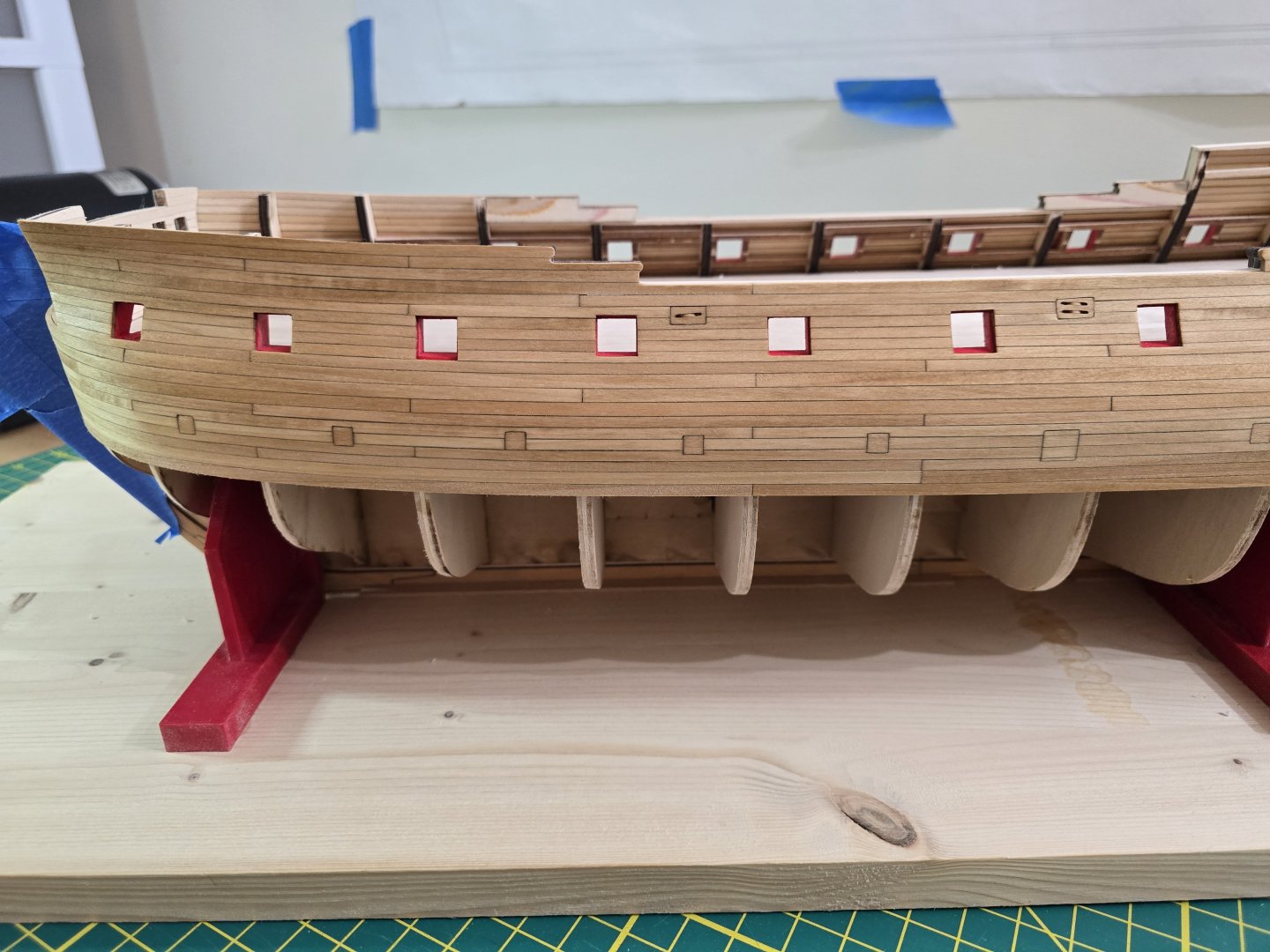
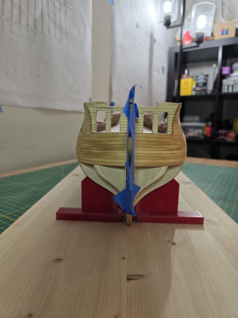
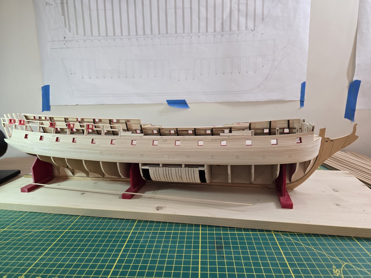
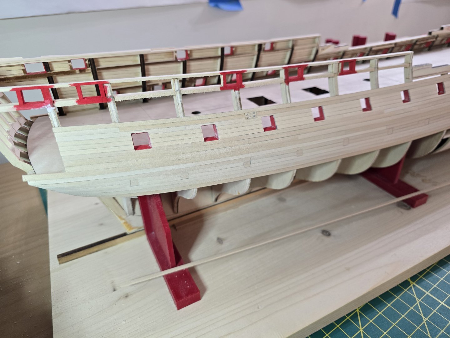
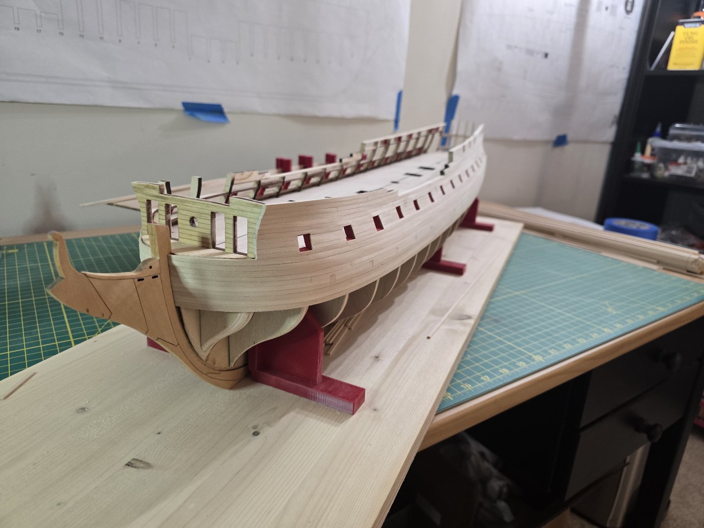
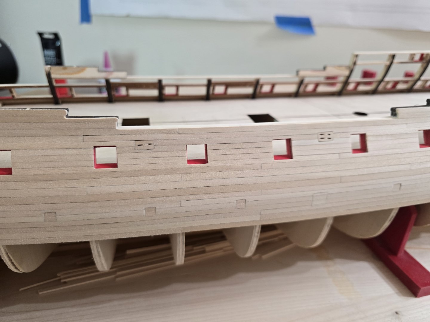
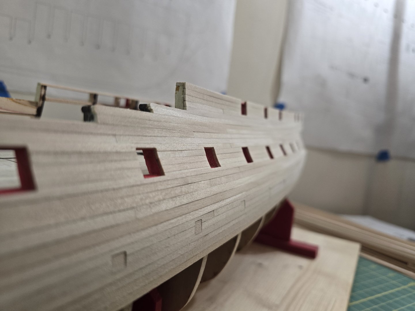
Hey all! I know it's been a while. I got sick a few times since December. I swear I caught everything that was going around. Anyway, it's taken a long time to tree nail! I'm almost done with the starboard side of her. I am counting every tree nail I make, so if you guys want to guess how many tree nails it took me for the starboard side, be my guest! I'll leave a few pics as to my progress. As you can see, I only have a small portion at the stern to finish. I know it looks like a mess right now. But I'll clean it up and stain/varnish this side before moving to the other side. I will have to touch up the black painted whales a little bit too. Anyway, this is a short update and I'll continue tree nailing! Thanks for following along! Jeff


-
Nicely done! It's coming along very well! Jeff
-
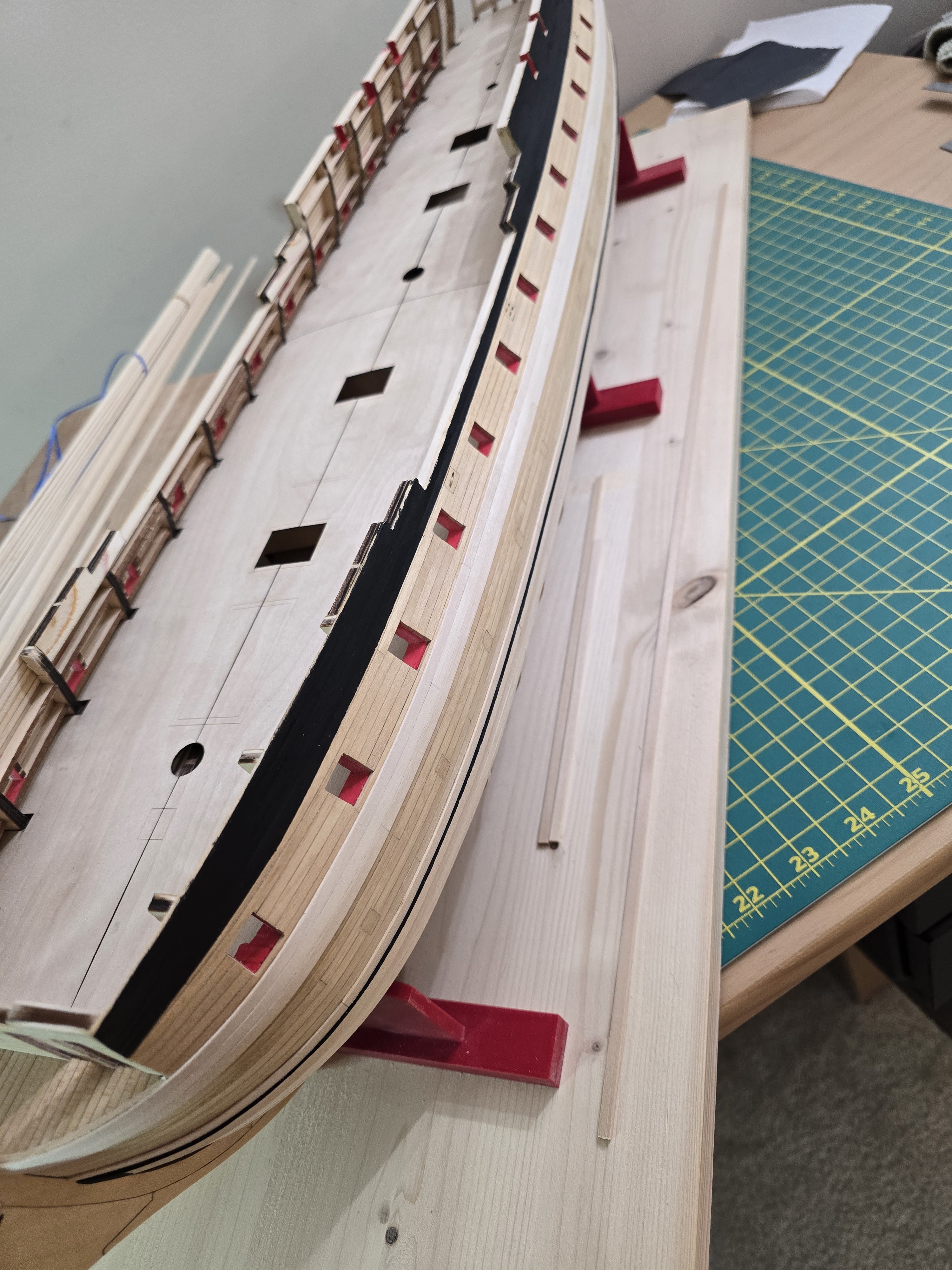
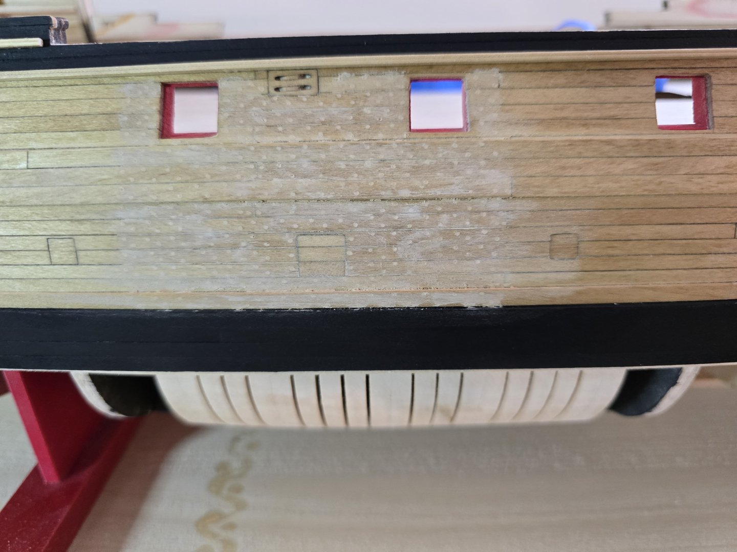
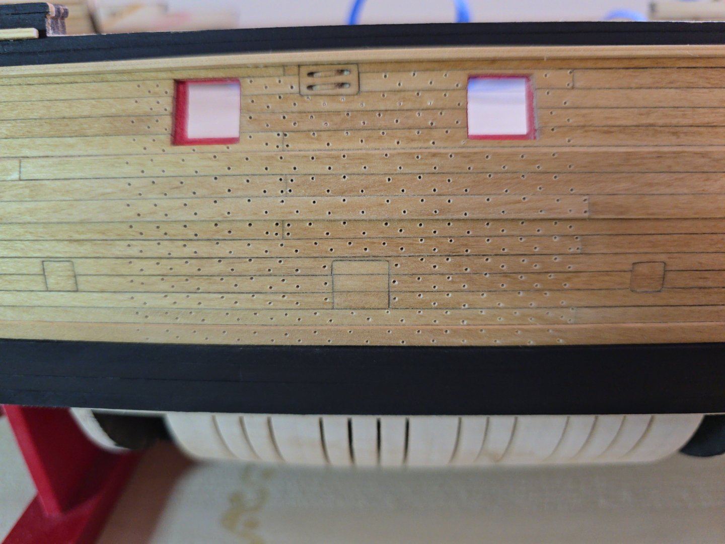
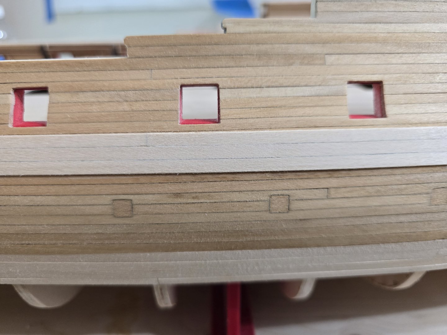
Hey all! So I have decided to tree nail the hull from the wales upward. But only the hull section that's not painted black. This is a pretty slow process and I'm trying to refine how im doing it. Like the instructions say, I first started on the side with the exposed hull section. I tried to line up the tree nails with the bulkheads as best I could. Here are some pics of my process. I first drill the holes. I place a piece of tape down to match where the ribs are, then I place a square next to the tape to try and make sure it's straight. I manually drill one column at a time until I have completed 3" of tree nails. It's hard to see the drill holes unless I have lower light. I then lightly sand the holes with 400 grit sandpaper just to clean up the tops from loose wood. I don't have enough an awl, so instead, I took a T pin to each of the drilled holes lightly touching just to make sure the holes are round. Afterwards, it looks like this. Then comes the messy part. I fill in each hole with natural wood filler (the kind recommended in the instructions) I then sanded it down to remove the excess. I hope you can see some of it. I have to sand more of the excess off. Sometimes it's really hard to tell if I sanded enough, so I have to take a very lightly damp cloth and rub the hull for the tree nails to appear. I had to do that with the pic above, but i can tell it needs more sanding. I do think it will look really nice once it's done. This will be a very labor intensive timely process. I will try to give update as to how its going in a few days. Wish me luck! Jeff


-
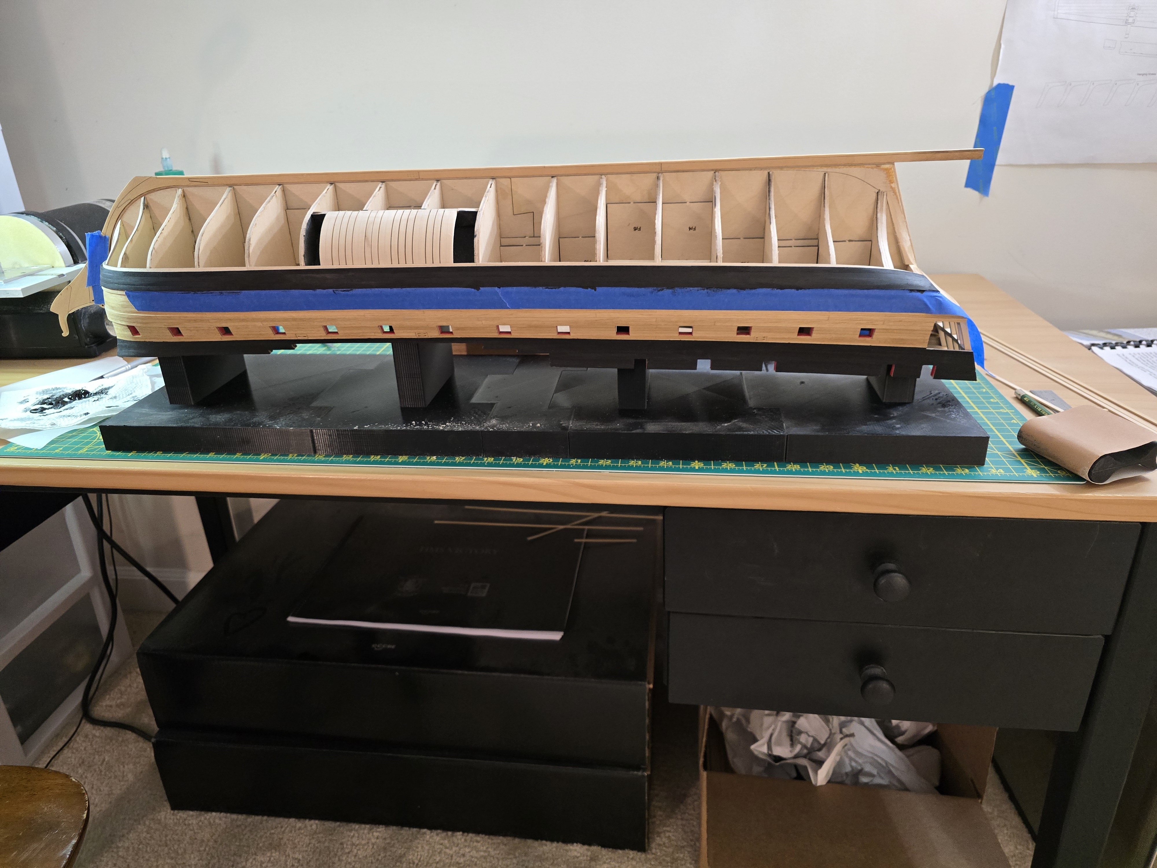
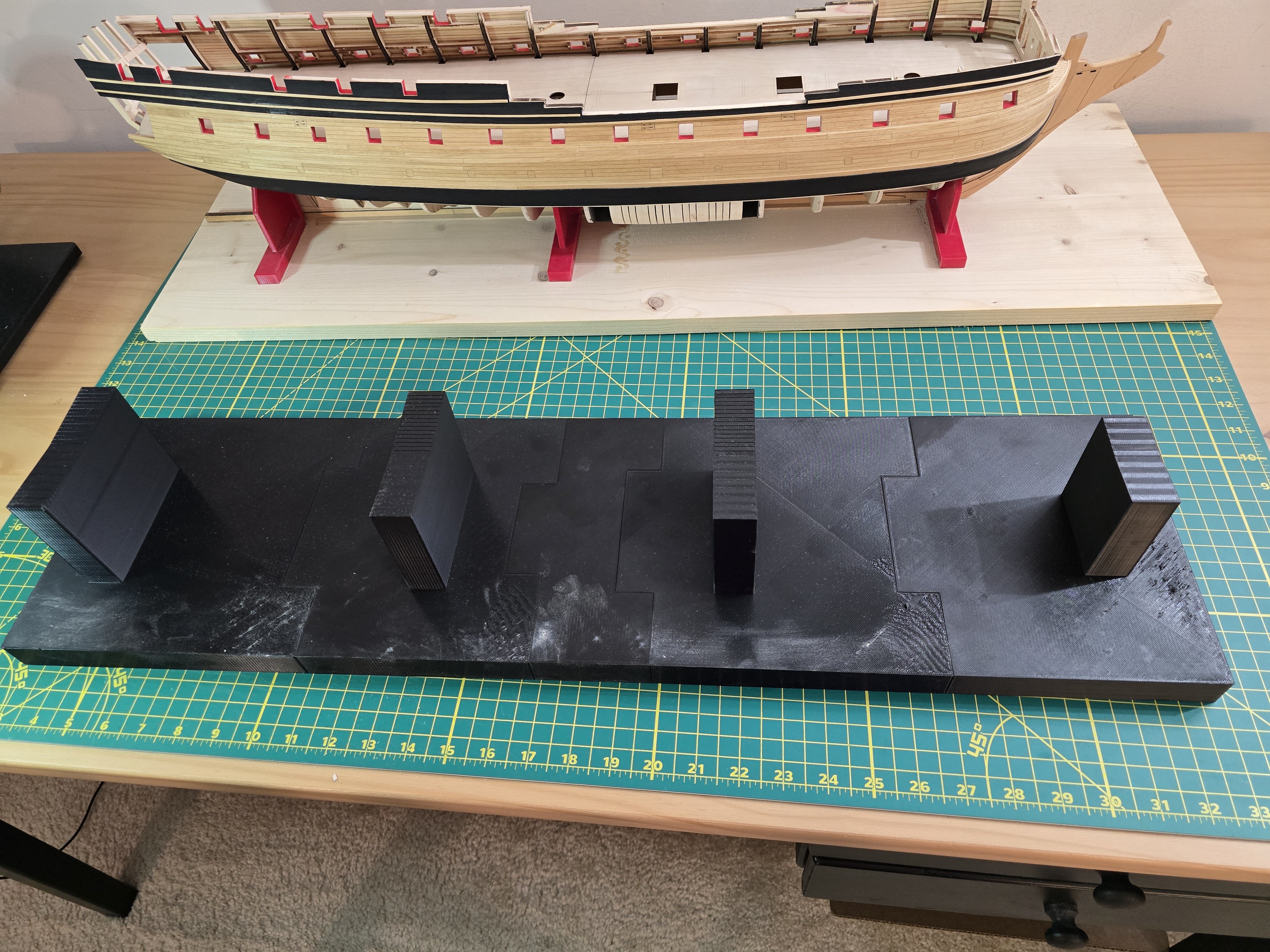
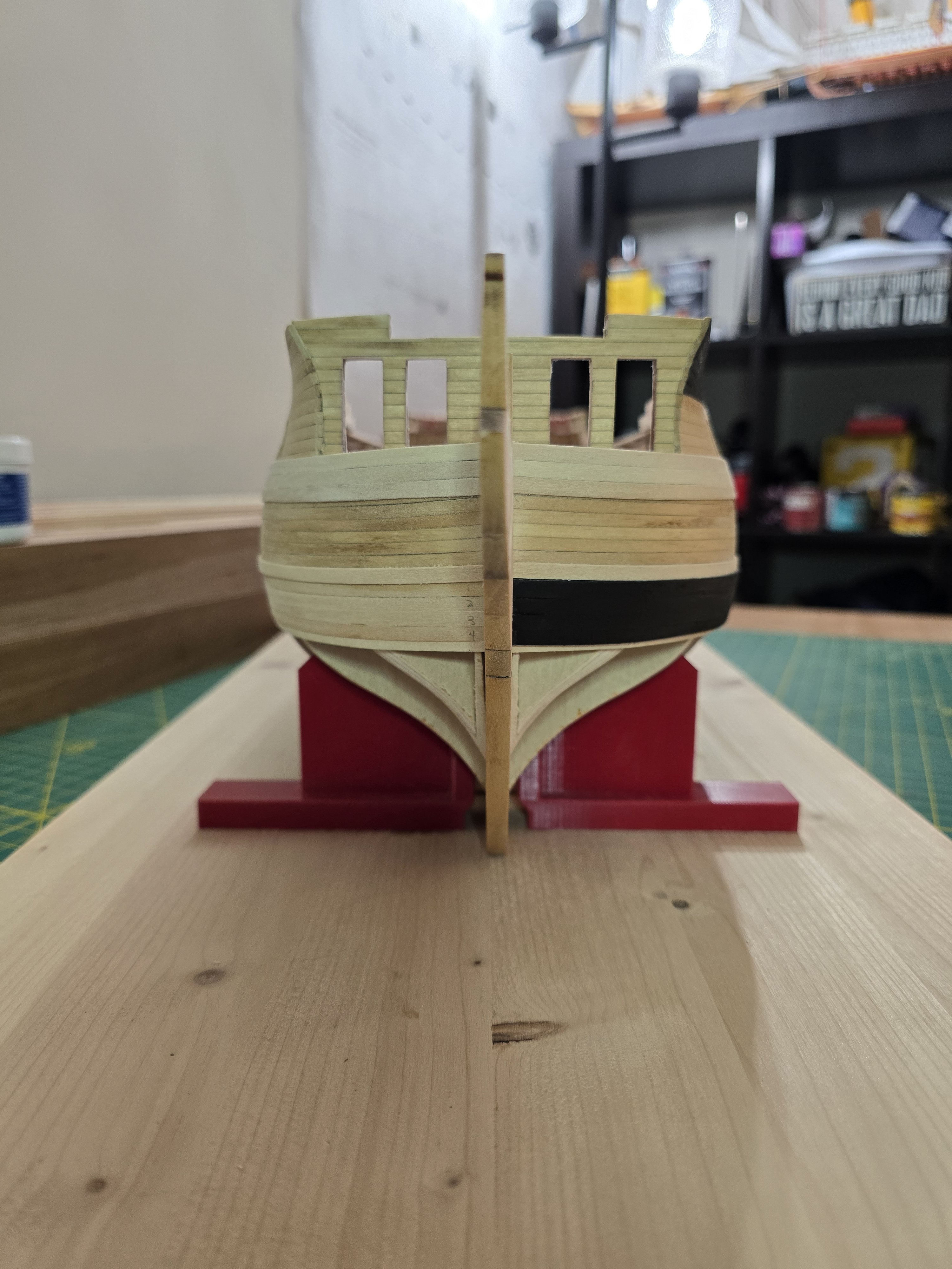
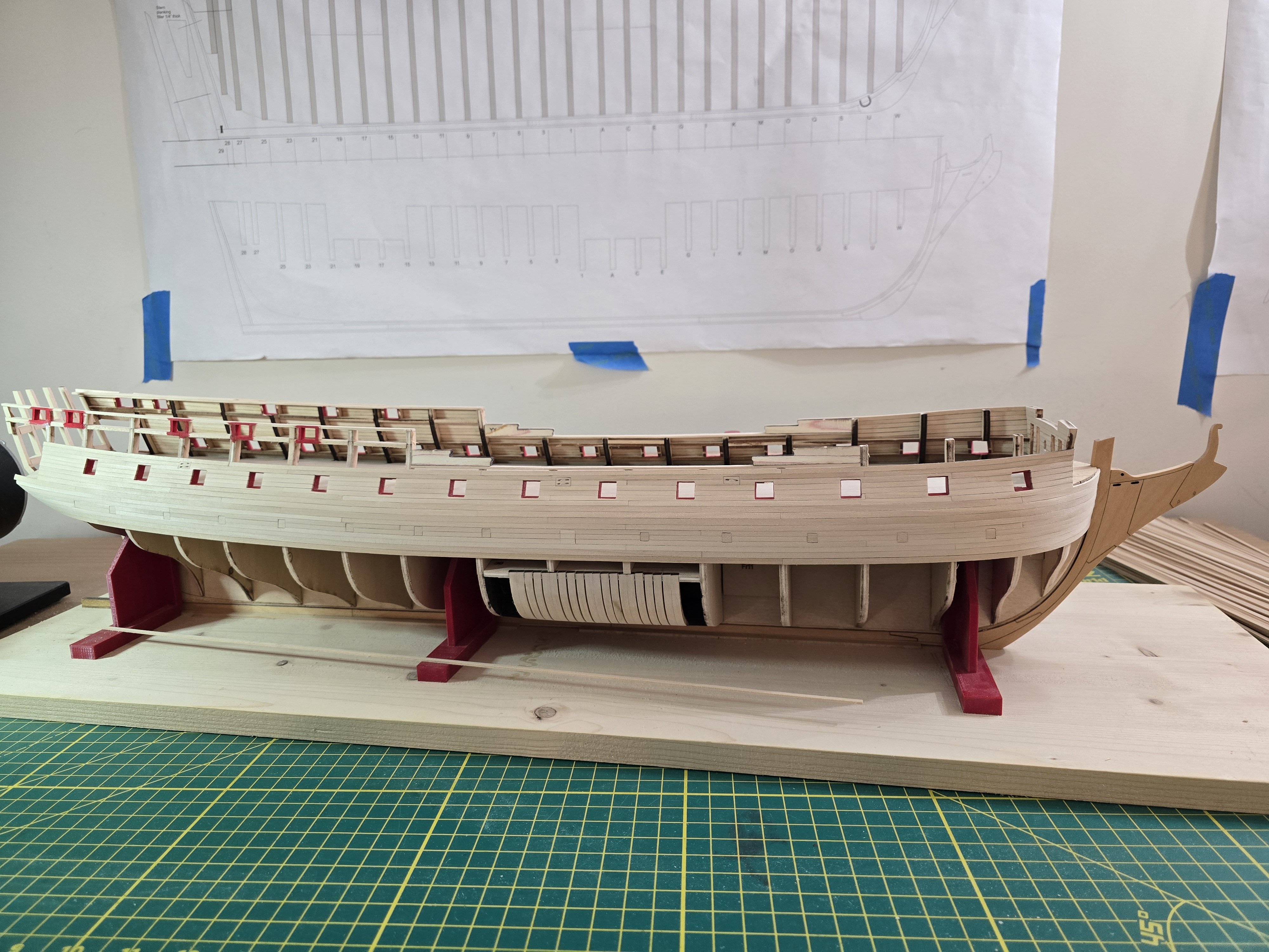
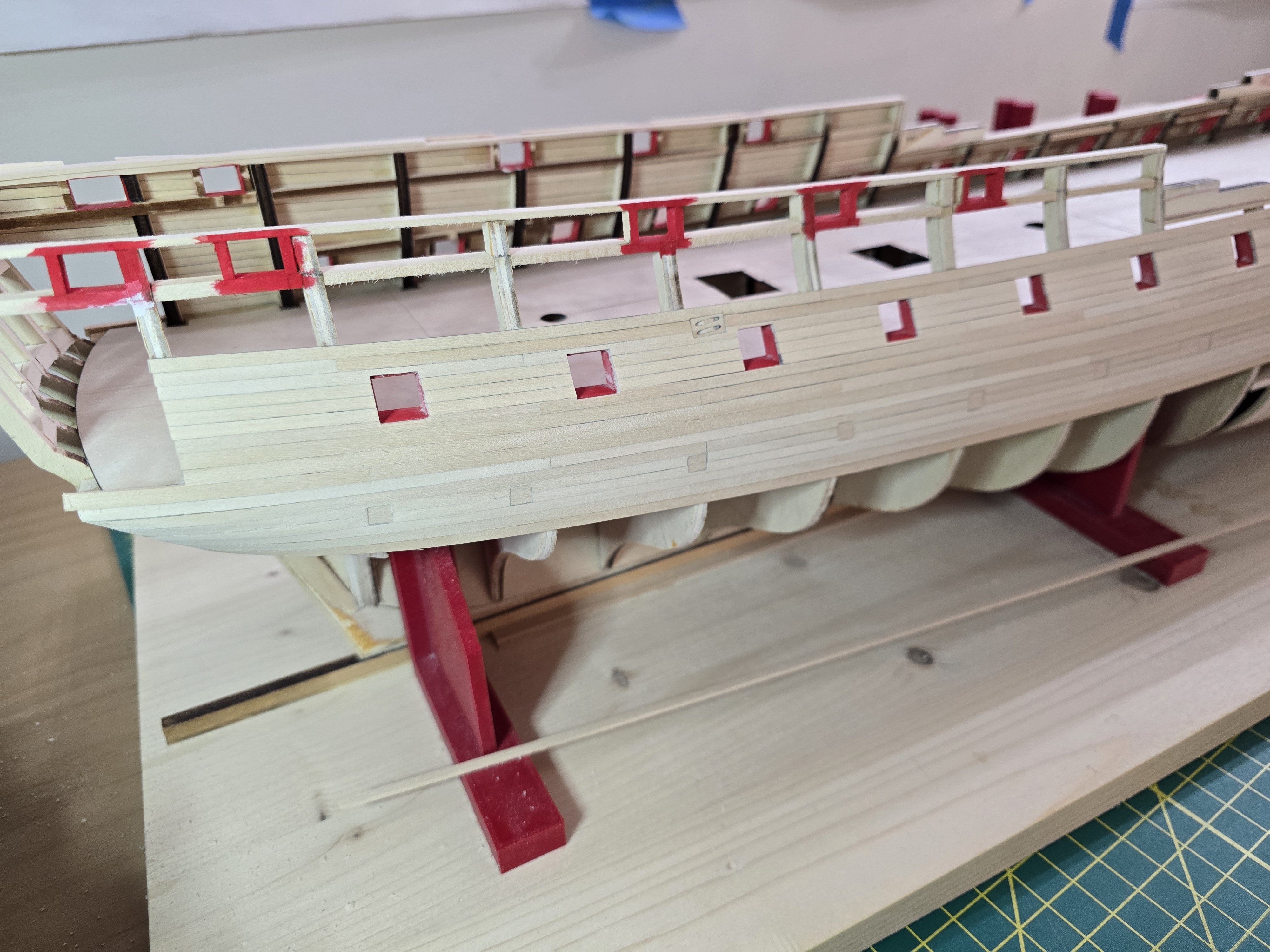
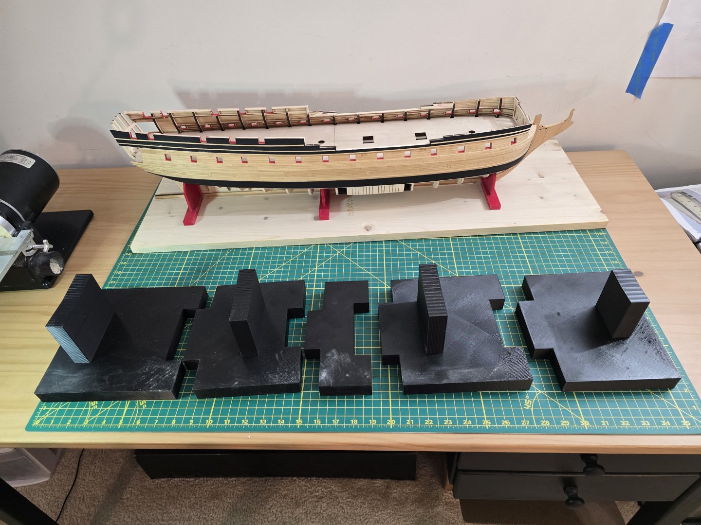
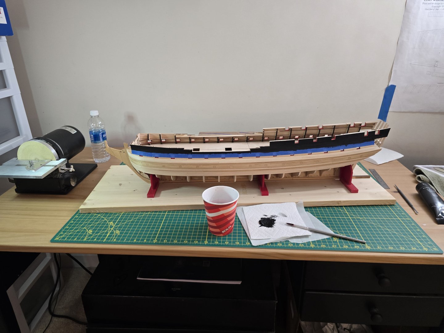
Happy 2025 everyone! I finally felt better enough this week to make some progress. I have completed the other side wales and decided to put the molding on like the other side. I already described how I complete the wales and molding in previous posts, so I'll just post some pics of both sides finished. Oh, I have to note. I 3D printed a new holder for the ship while she is upside-down. I made the design in Blender after measuring the ship and where I wanted the supports to go. I made 4 support points. Each connection joint is a different size so that the holder only fits in 1 way. It took quite a while to print as each piece must be able to be printed within the size limitations of my 3D printer. Whew! Finally those steps are completed! I would like to start tree nailing, but I'll wait until tomorrow to start. Thanks! Jeff


-
@Wawona59 Hi John! Thank you for following my build log! I apologize for not replying sooner. I caught pretty much everything since before Christmas and I'm finally starting to feel better. Like you, I had my Confederacy kit sitting away for years before I felt mostly comfortable to start her. It was fun just looking at the box with anticipation. Haha! Thanks for following and I hope you and everyone have a great 2025! Jeff
-
@wernerweiss Thank you for your thoughts. I do appreciate the critiques, especially from someone who has finished The Confederacy! By the way, you have a great build log of her and you did a fantastic job. Your Confederacy is excellent. Jeff
-
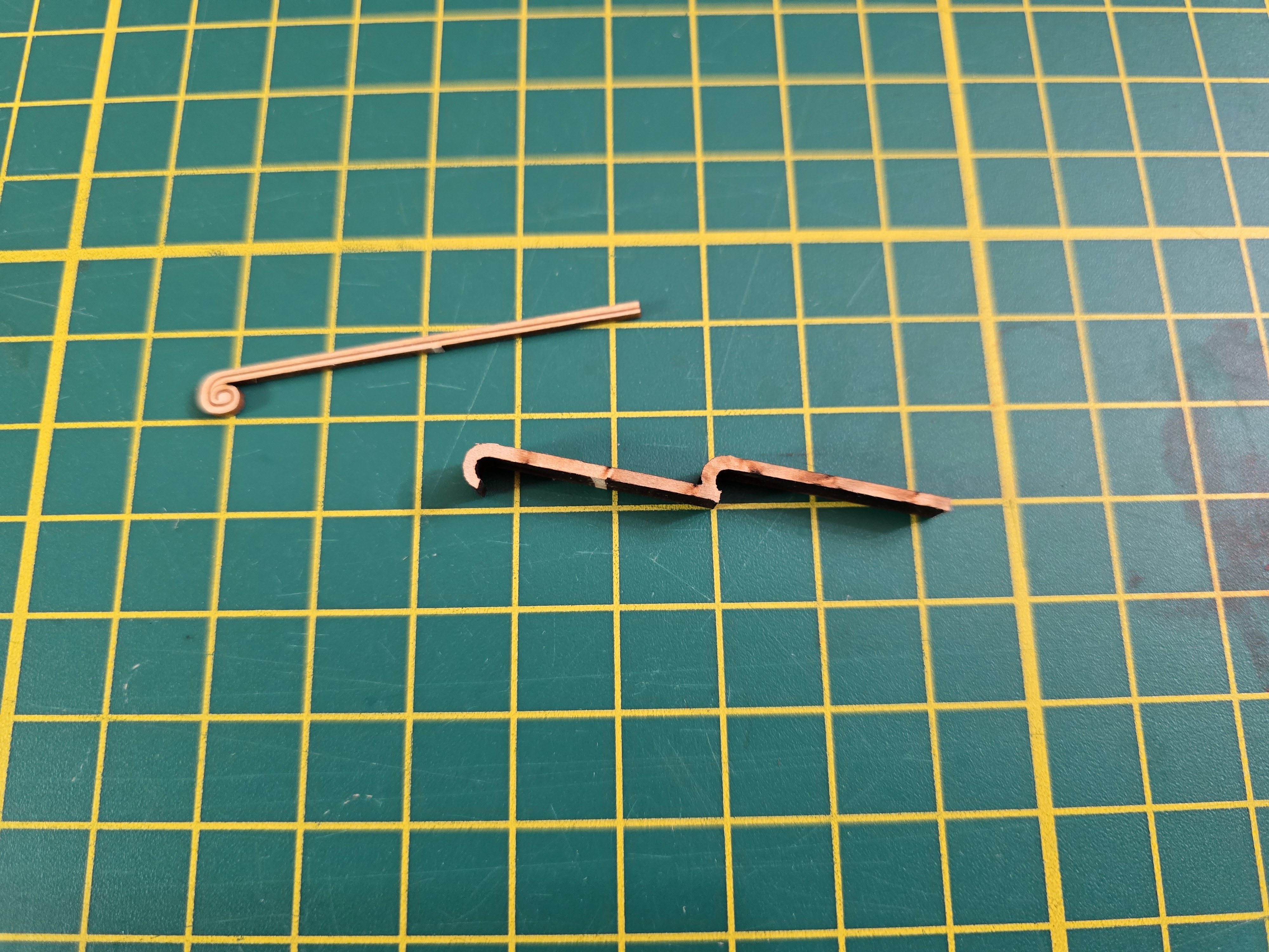
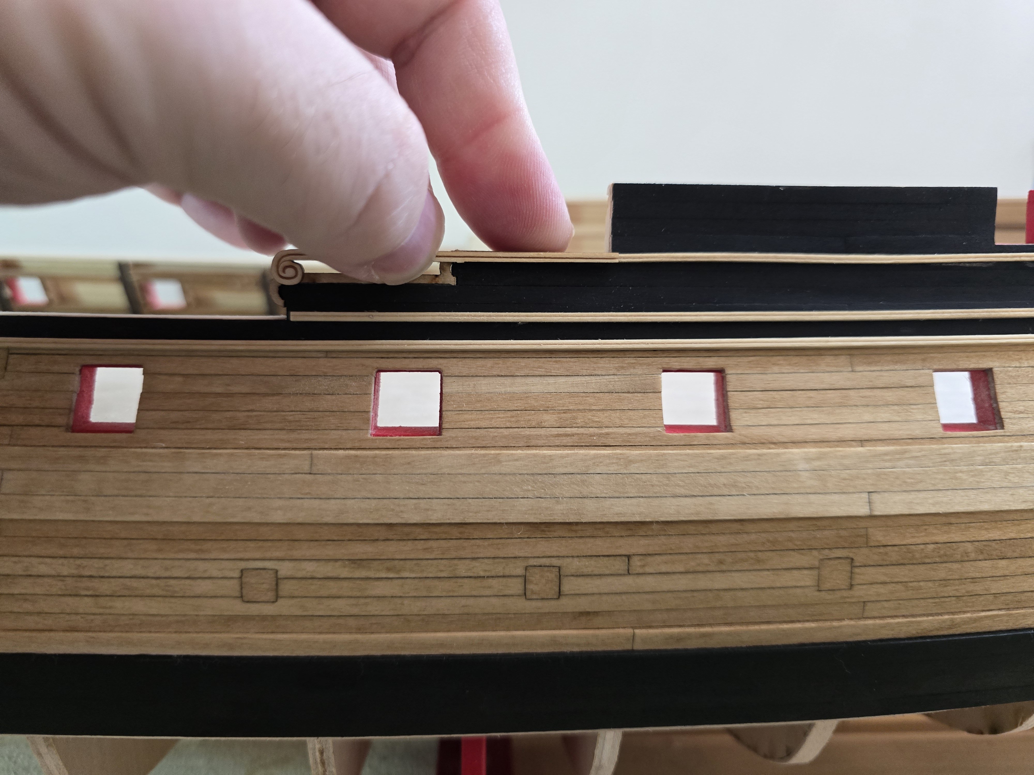
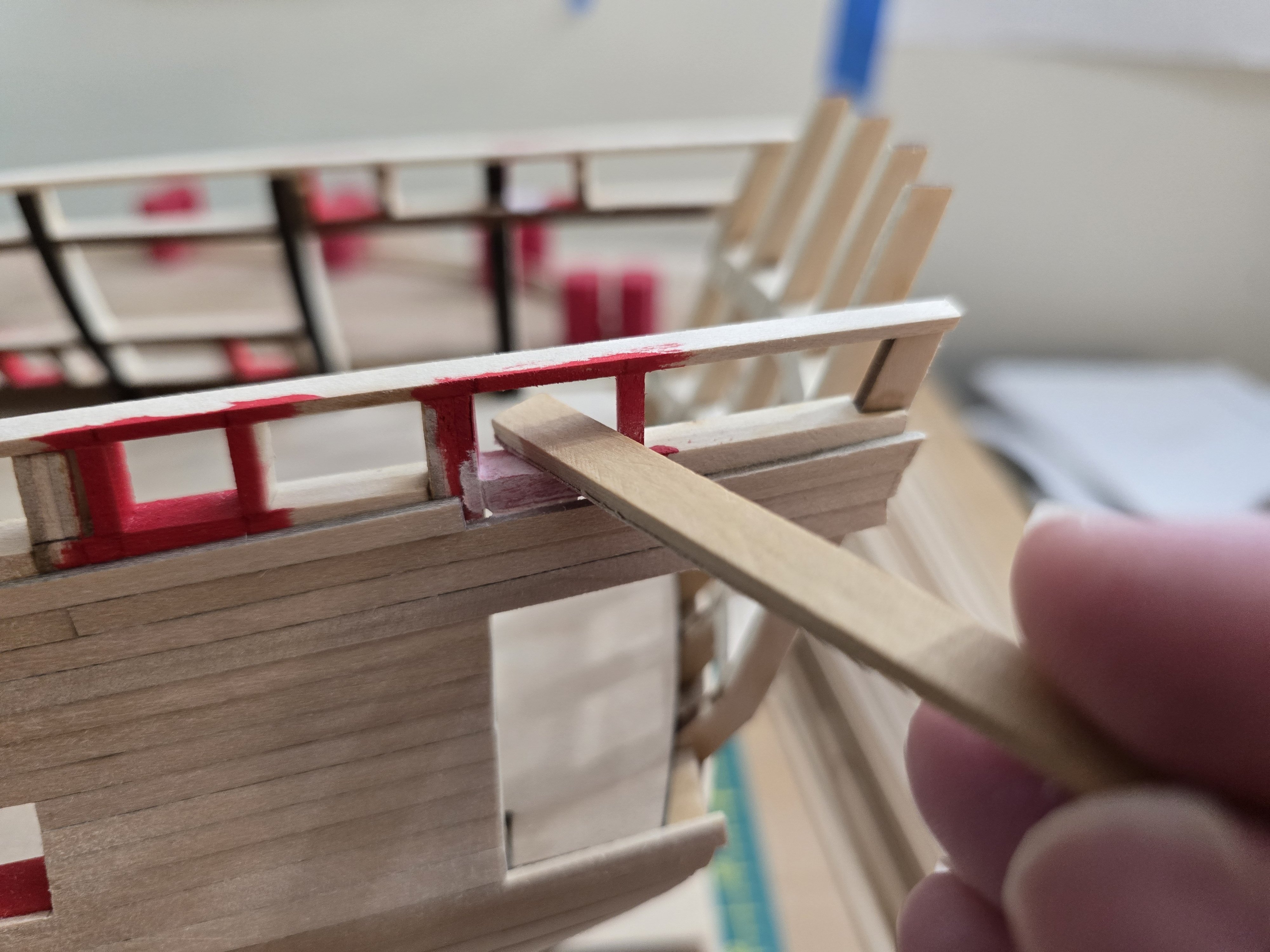
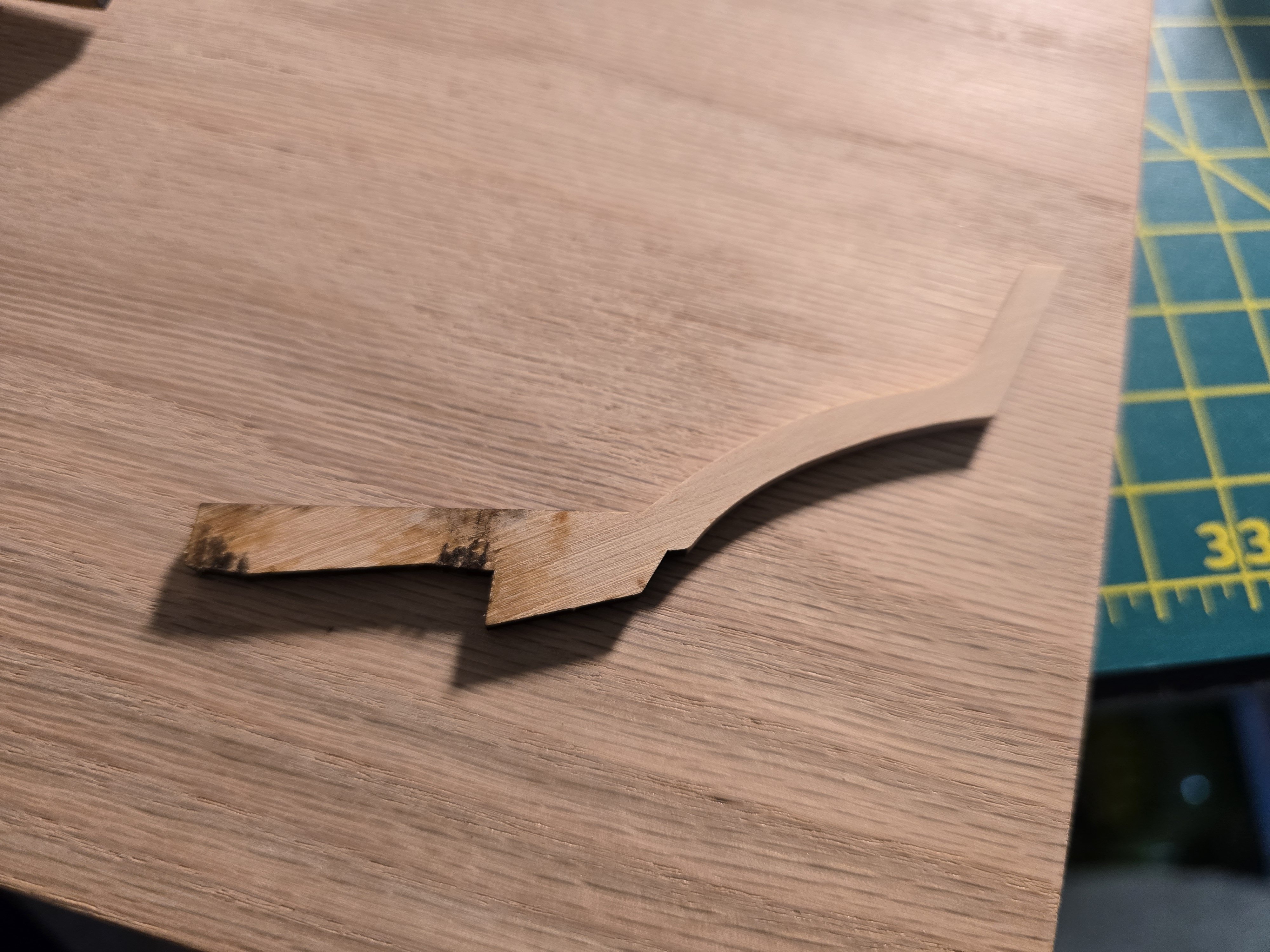
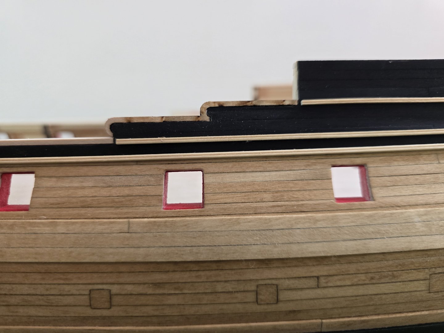
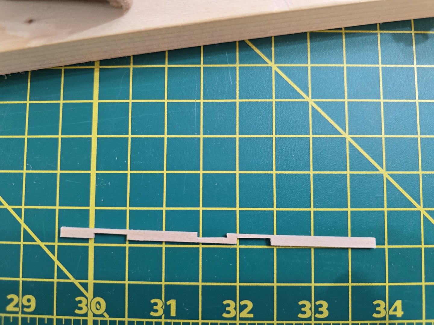
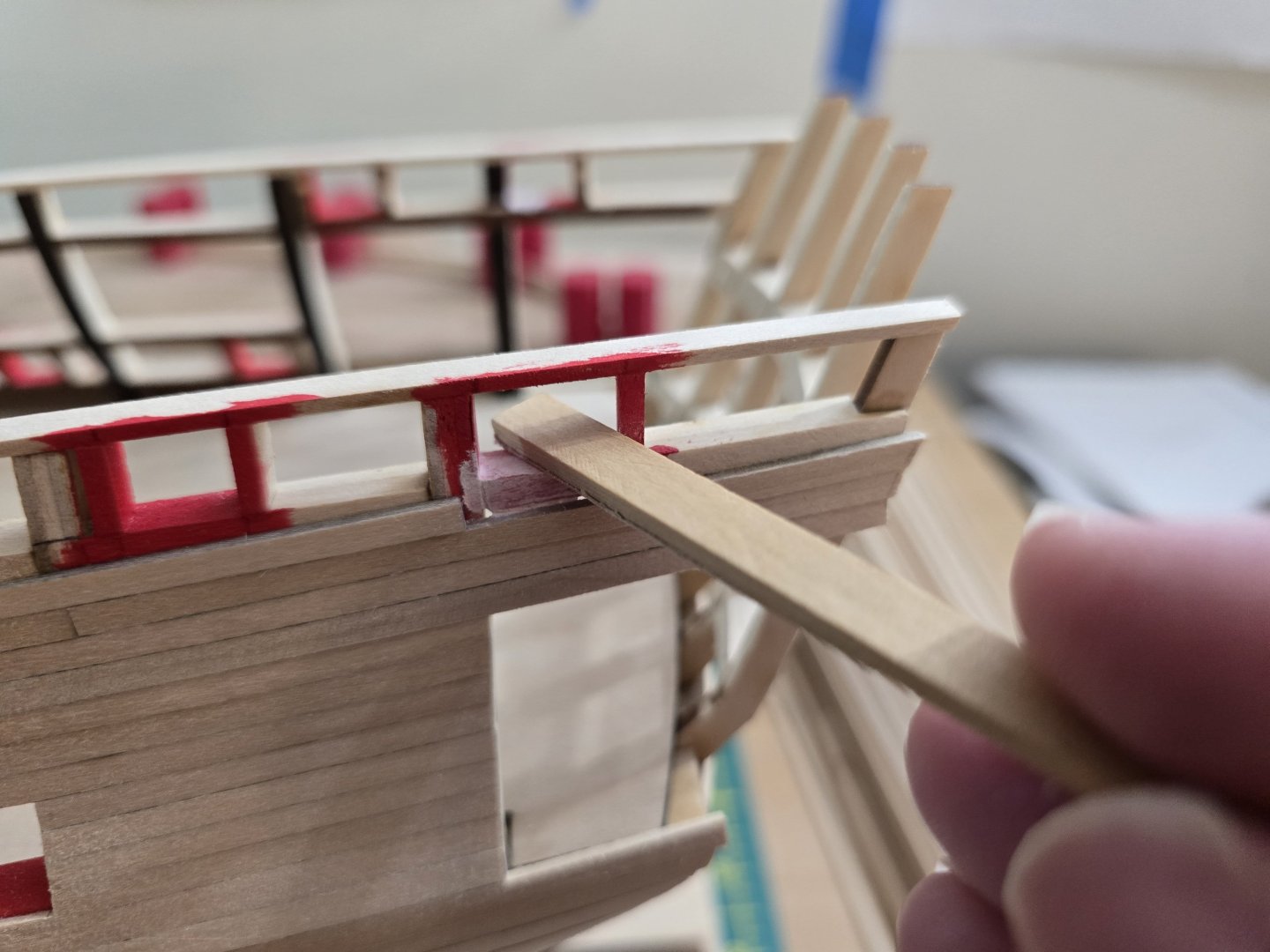
@wernerweiss Hello! I wanted to let you know that I have not glued the cap rails on yet. Gluing the cap rails is on page 118-119 in the instructions and I'm on page 42. I wanted to make sure that the molding strips would be at the correct placement, so I cut out a cap rail and a volute laser cut piece and test fitted them to the model. I also placed (not glued) the 1/16" strip ontop of the waist as well to check the lower molding strip. This next pic shows the cap rail in place along with the waist piece. This pic is where I have overlapped the volute piece over the top of the cap rail and ontop of the molding piece I glued on earlier. It seems to line up with the molding very well! I think I have the molding pieces glued into the correct position on the model. On page 39 of the manual, it states that finishing the wales/molding/painting is optional at this point of the build if the builder wants a break from planking. I sure wanted a break from planking! Haha! So that's why I continued with the optional steps before continuing to plank the hull. Thanks for your feedback! Jeff


-
@wernerweiss Hey! Thanks for the feedback! I did check the instructions too, and it does specify to add the molding first next to the waist. I did check the laser cut cap rails to see how far back they are cut to match up with the molding pieces. The instructions say, to place the molding pieces correctly, place a 1/16" strip ontop of the waist and make sure the molding strip sits evenly with it. I also checked the instruction photos and it also shows the molding strips sit slightly back, not up to the edge of the waist. I think you have a good idea of adding the channels along with the molding strip to make sure it has a nice curve. Also doing so won't make you cut out the molding strips where the channels will go. I might do this with the other side, but i haven't decided yet. I can be a little clumsy and if I have channels sticking out from the hull, I might accidentally knock them off! Haha! Thanks for your input! Jeff
-
Hey all! Happy holidays and new year! I added the molding strips to one side of the hull and wanted to share some pics. I tried my best with it. I did stain them first before gluing them on. Now into the other side to repeat the entire process! Thanks all for reading! Jeff


-
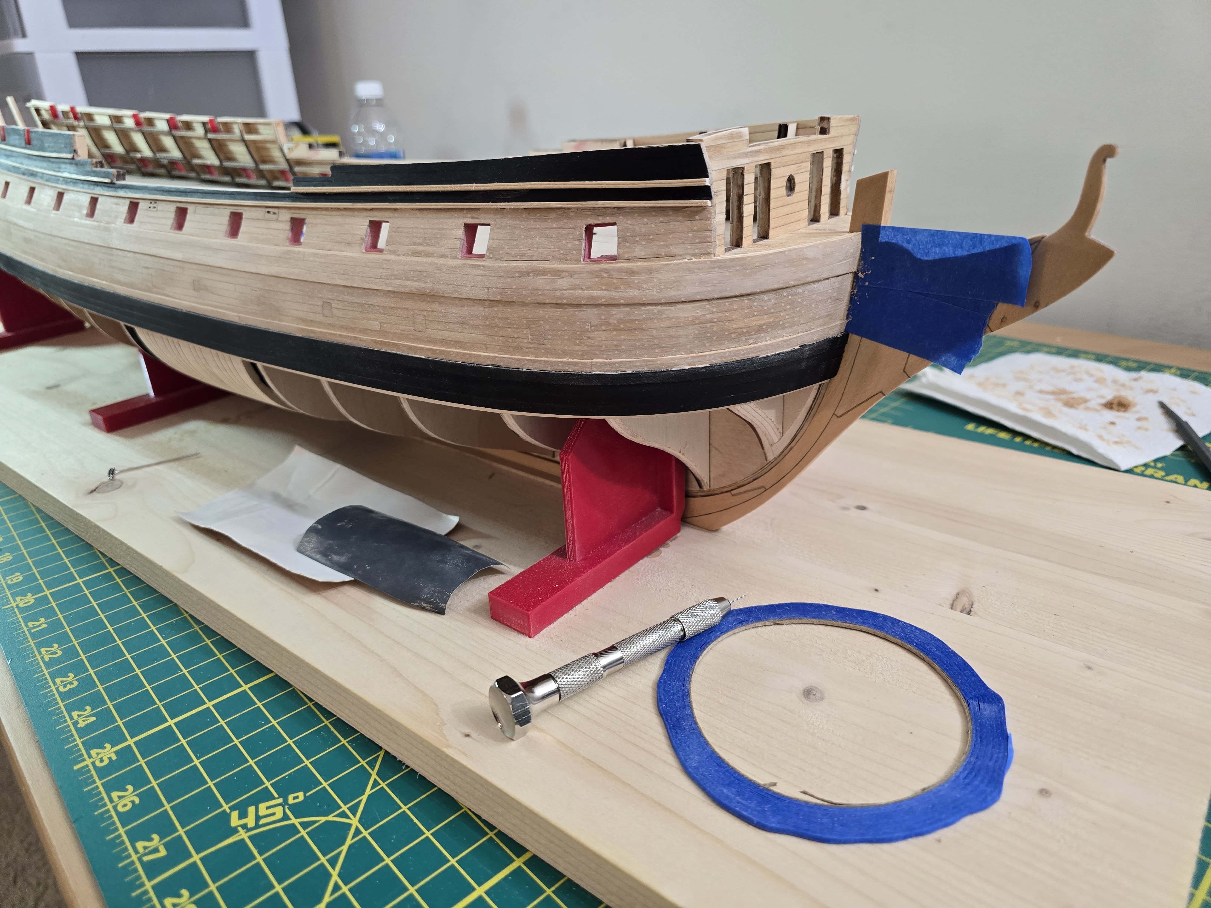
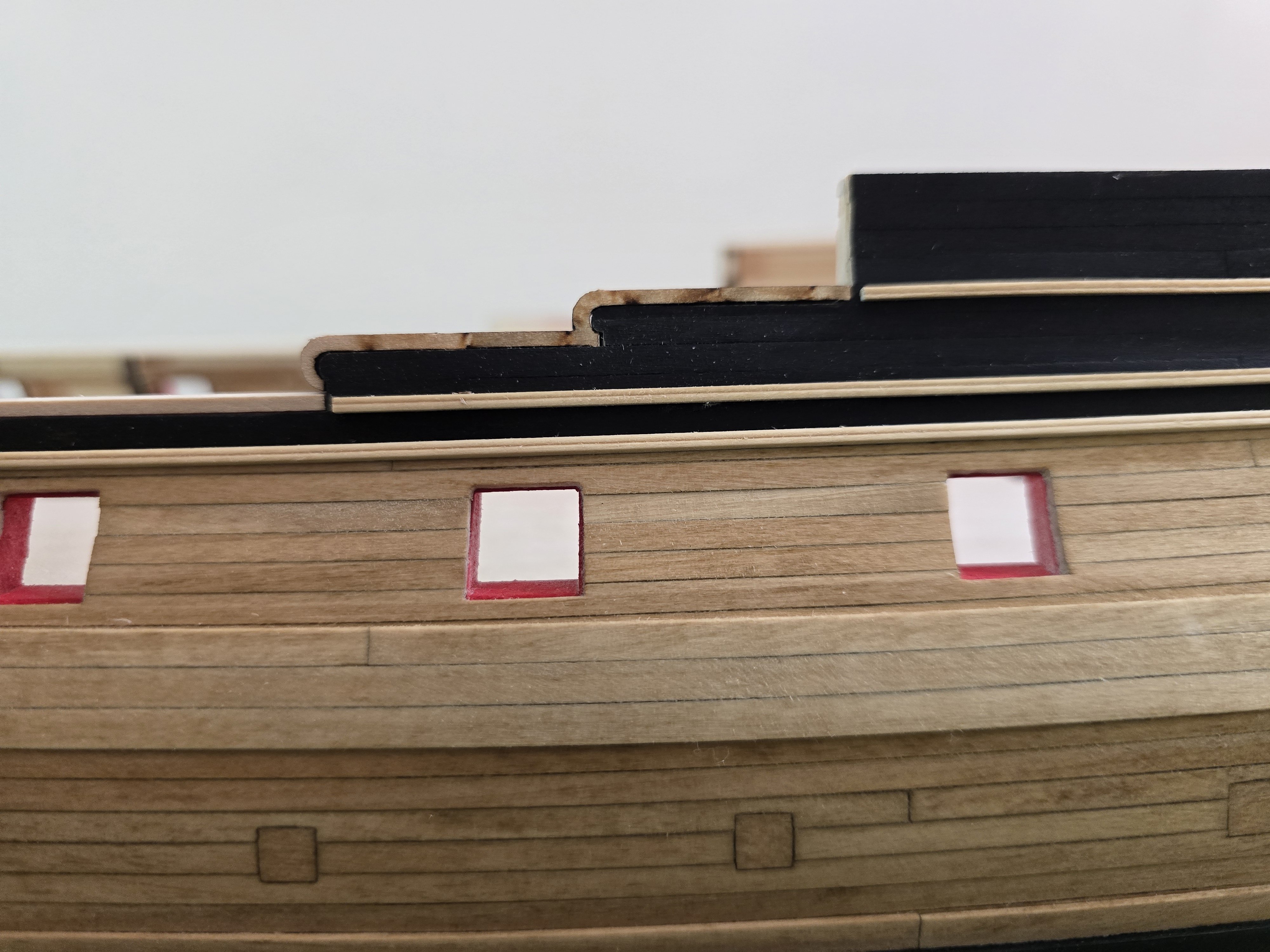
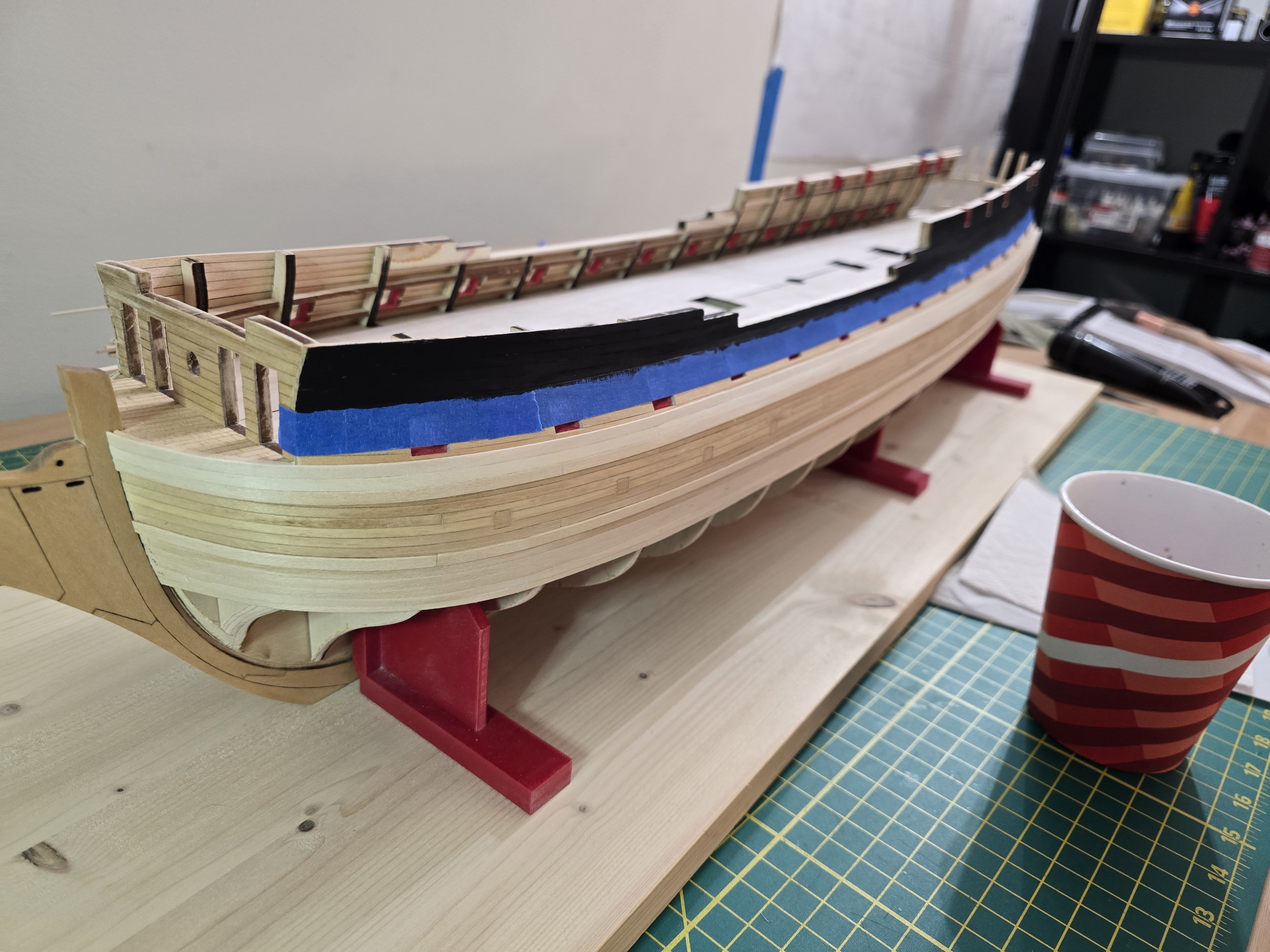
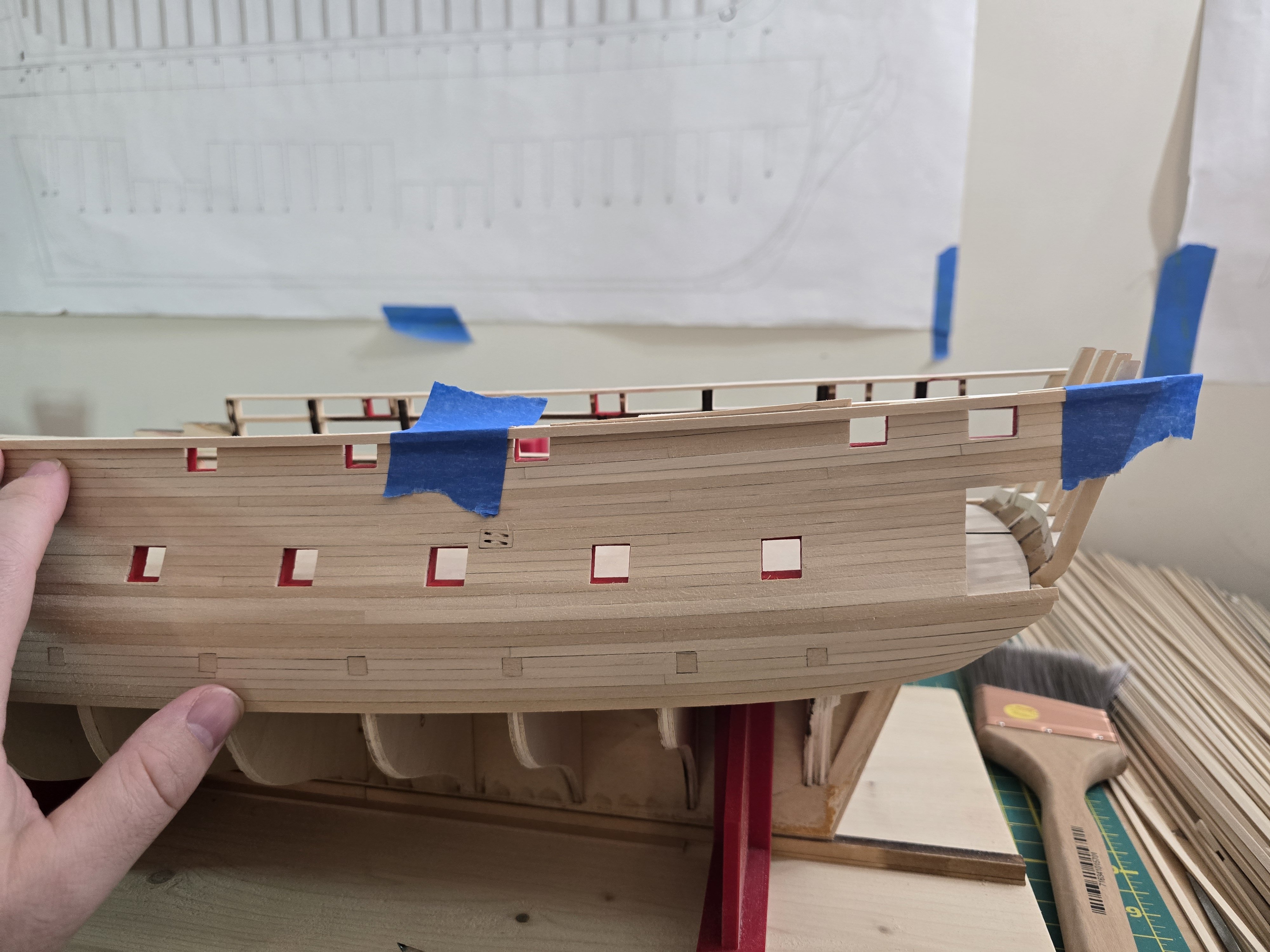
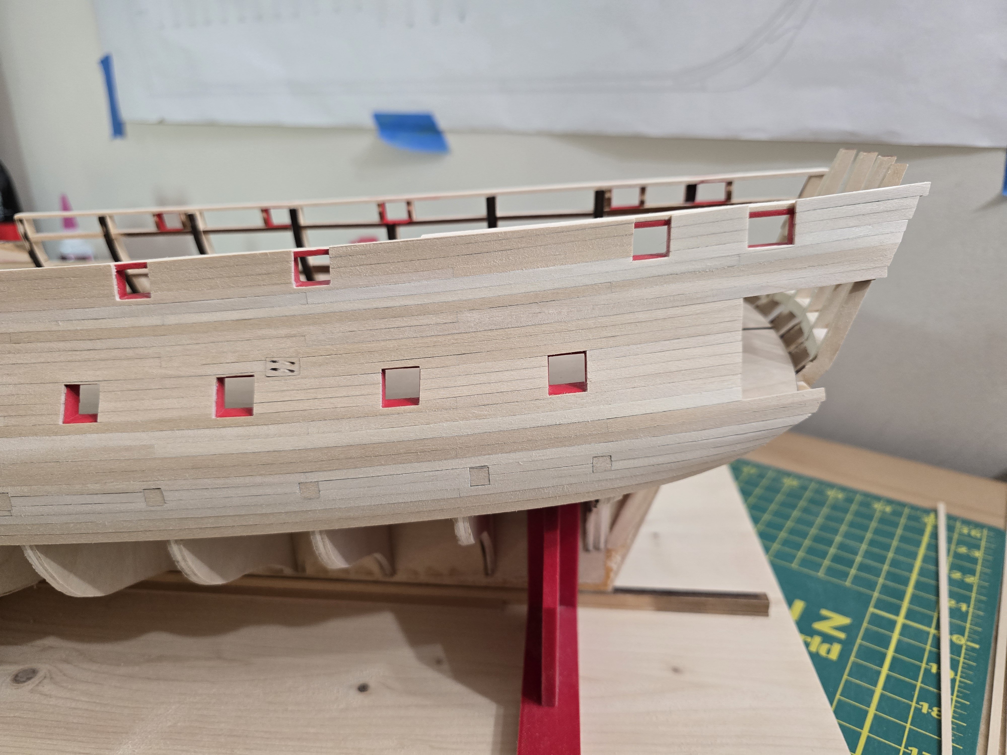
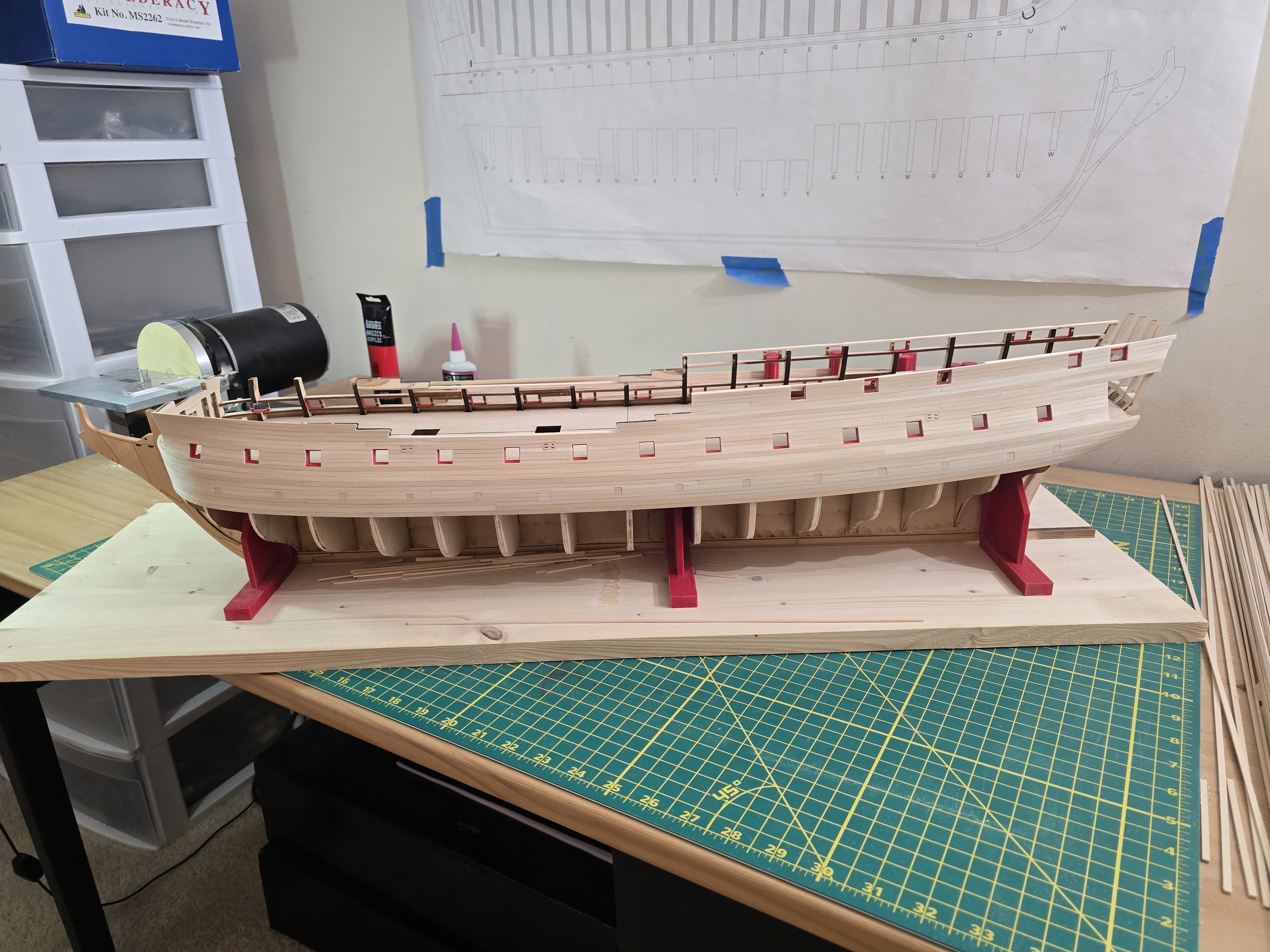
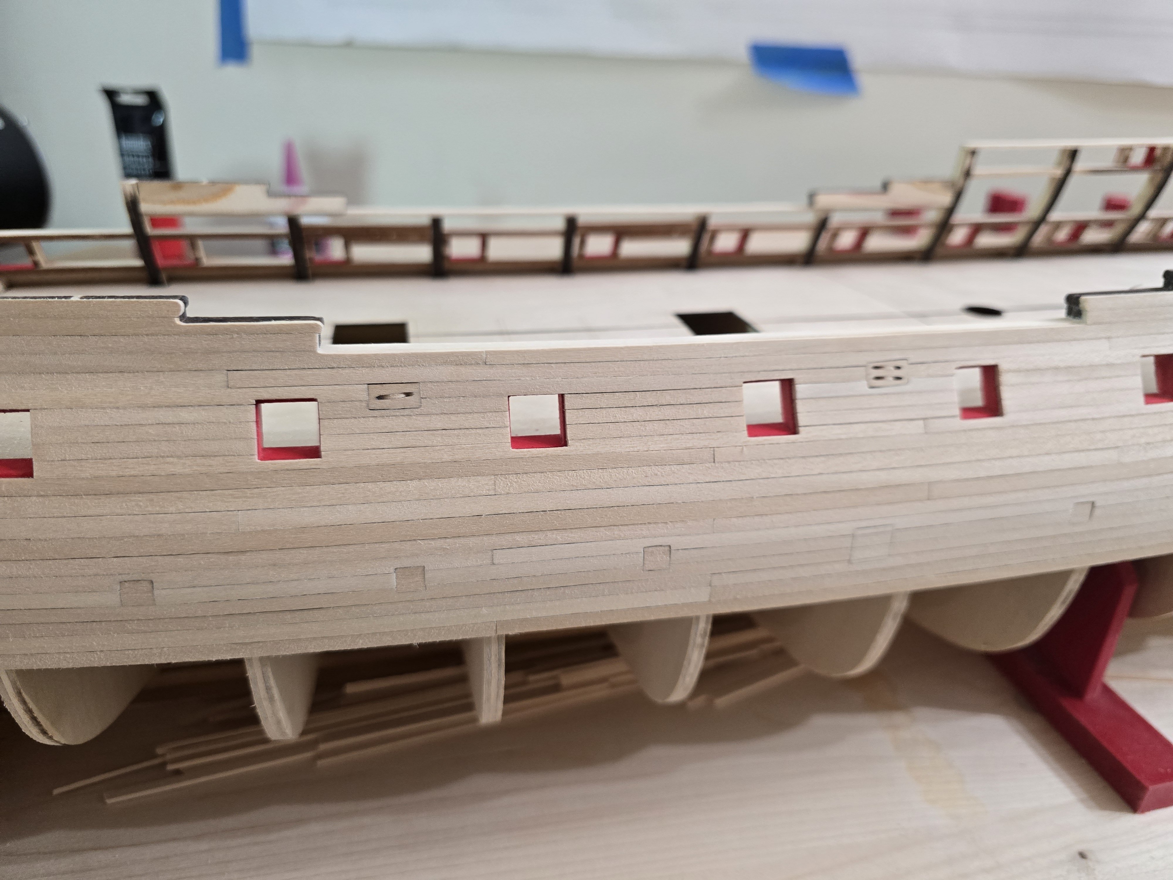
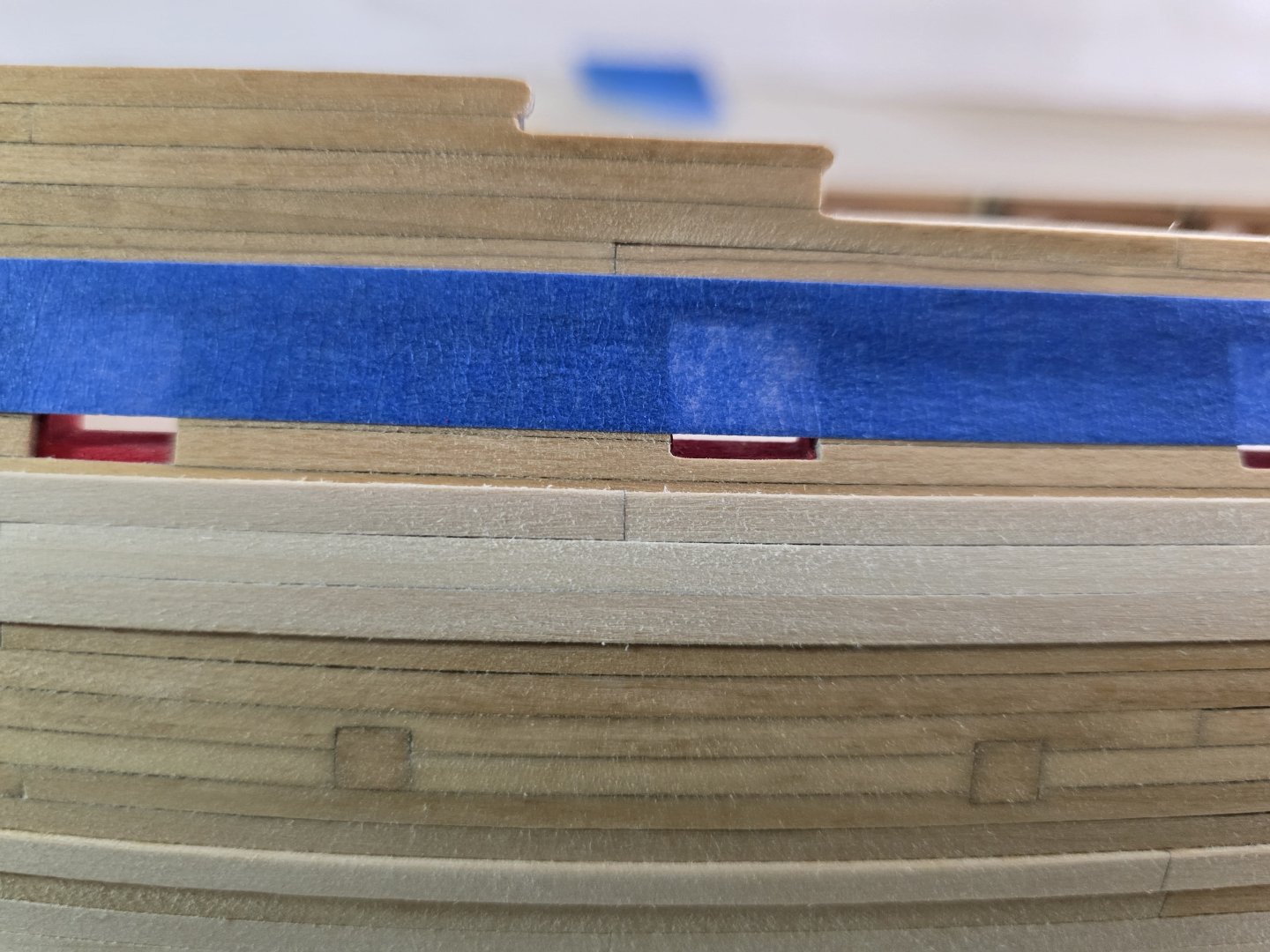
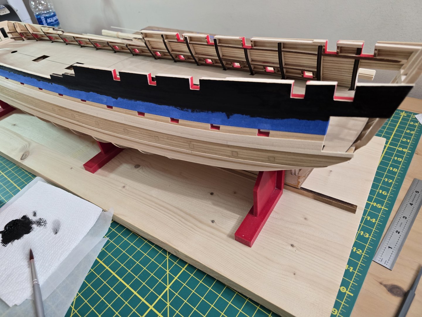
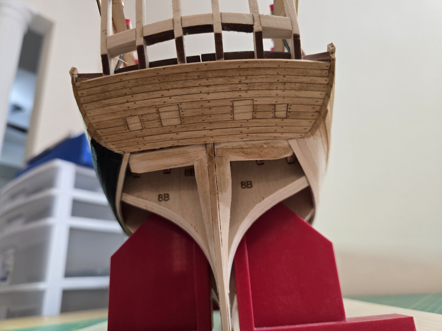
Hey guys! It took me a little bit of time to decide what to do next. I decided to do things are little out of order. First, I placed painters tape where the lower molding strip will go and made sure it was a good even curve. Then I marked it with a pencil. I then took the tape off and re positioned it slightly below that line. I hope the pic comes out ok. The reason I placed it below that line, is so that the black paint will overlap the molding strip so it will look even. I then proceeded to fill any gaps ( there were 2 very small gaps) and sanded it down smooth. This was done for the planks above the tape. After this was complete, I pained the planks black above the painters tape. During this process, the wood strips arrived from Model Expo! So I knew I was going to complete the main wales next. There was a slight problem though. I accidentally wrote down the wrong number of strips. The main wales are 4 rows of 2 planks each. So that's 8 planks total. But I like 2 extra strips just in case. My issue was, I wrote down 10 strips when I needed at minimum 16 strips. Yup. My bad. But Model Expo was quick to take my order and deliver the 10 strips free of charge. So that was super nice of them. I'm not sure what I'm going to do for the other strips I need to finish the main wales. I'll figure it out. Anyway, I then started the main wales on one side of the ship. I'm the first to admit, I'm not that great with putting painters tape down and not having some paint run through the tape. So before I placed the top main wale plank, I rounded the top edge then pained mostly just the top edges black. This should hopefully make for a much cleaner look than placing the top wale strake on first. This allowed me to not have to worry about painting the top edge and accidentally painting the black strake. I continued down the 4 plank rows. Since these will be pained, I applied some filler to smooth out any small gaps or ubeaven surfaces. As i was planking the wales I noticed my lower counter tree nails weren't great. What I mean is, I did not sand enough of the wood filler off the counter so it looks sloppy. So I sanded the entire lower counter again to get off the extra wood filler. Once all this was completed, I taped up the side for painting the main wales. I then proceeded to pain the wales. This was the result. That was satisfying to see it with the wales pained. I then decided to stain and varnish both sides of the ship. This will include the channel wales, Blake strake, and the lower counter again. I wanted to do both sides because it seemed like the right thing to do. But before doing this step, I had to get the molding strips ready. I followed the directions in the instructions using the provided molding scraper. This is how it turned out. This third picture was important because to make a good clean run of the molding, the bottom most requires 2 molding strips. You have to be careful when picking and sanding both strips. Some of the molding strips were wider than the others. So you have to choose 2 which had the same width or it will look off when glued on. Then last night, I stained and varnished both the ship and the molding pieces. I stained/varnished the molding pieces before placing them on the model. Here is what it looks like varnished. It's currently drying so I can't work on it tonight. The last thing I will need to do is add the molding strips. Whew! That was a lot. Let me know what you guys think! Thanks! Jeff


-
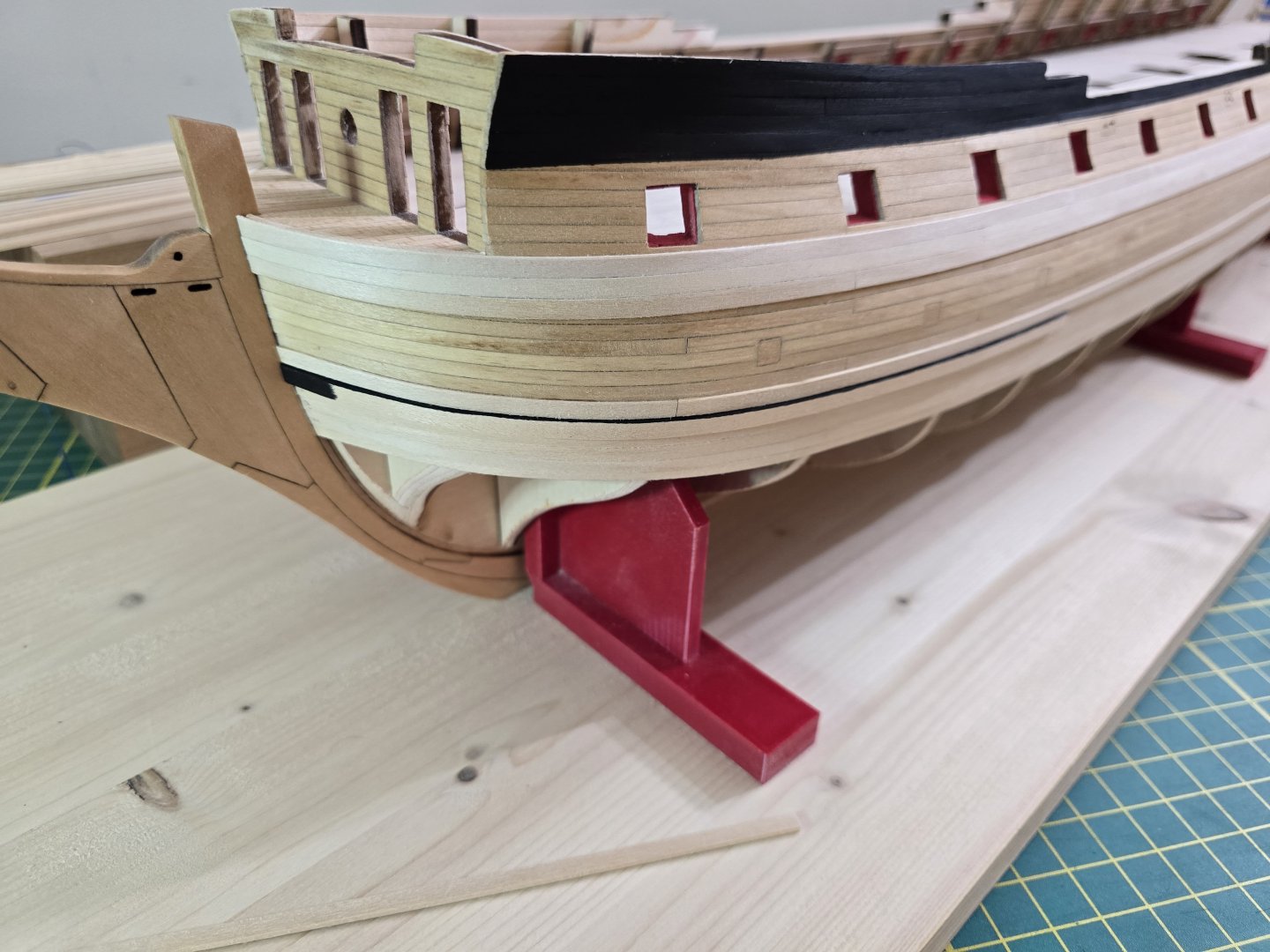
@CiscoH You are right. I'll have to get used to edge bending. But at least it's only for the wales, for now! Thanks for the kind words! I'm trying to take my time and not rush anything. Since my last update, I still have not heard back from ModelExpo about a few more 5/32" x 1/16" needed to start and complete the second layer of the main wales. I guess I haven't heard back yet because of Thanksgiving. I hope to hear from them soon. Because I don't have enough strips for the main wales, I instead added the channel wales and the black strake. I have been able to finish adding both! Here are some pics. I first completed the channel wales. After the channel wales, I then added the second layer black strake. This was a little tough to try and make the strake run nicely down the hull. I feel it's easier to spot a misaligned strake on bigger models than smaller ones! Here are some pics of the ship after I added the black strakes. I'm not sure exactly what to work on next. Should I continue with the molding strips; painting/varnishing, then tree nailing? Or wait for the wale strips and start planking below the wales? I'm leaning towards adding the molding strips and paining / varnishing. I really don't want to starting planking lower down the hull until all these steps including the wales are completed. Thanks everyone for your likes! Jeff


-
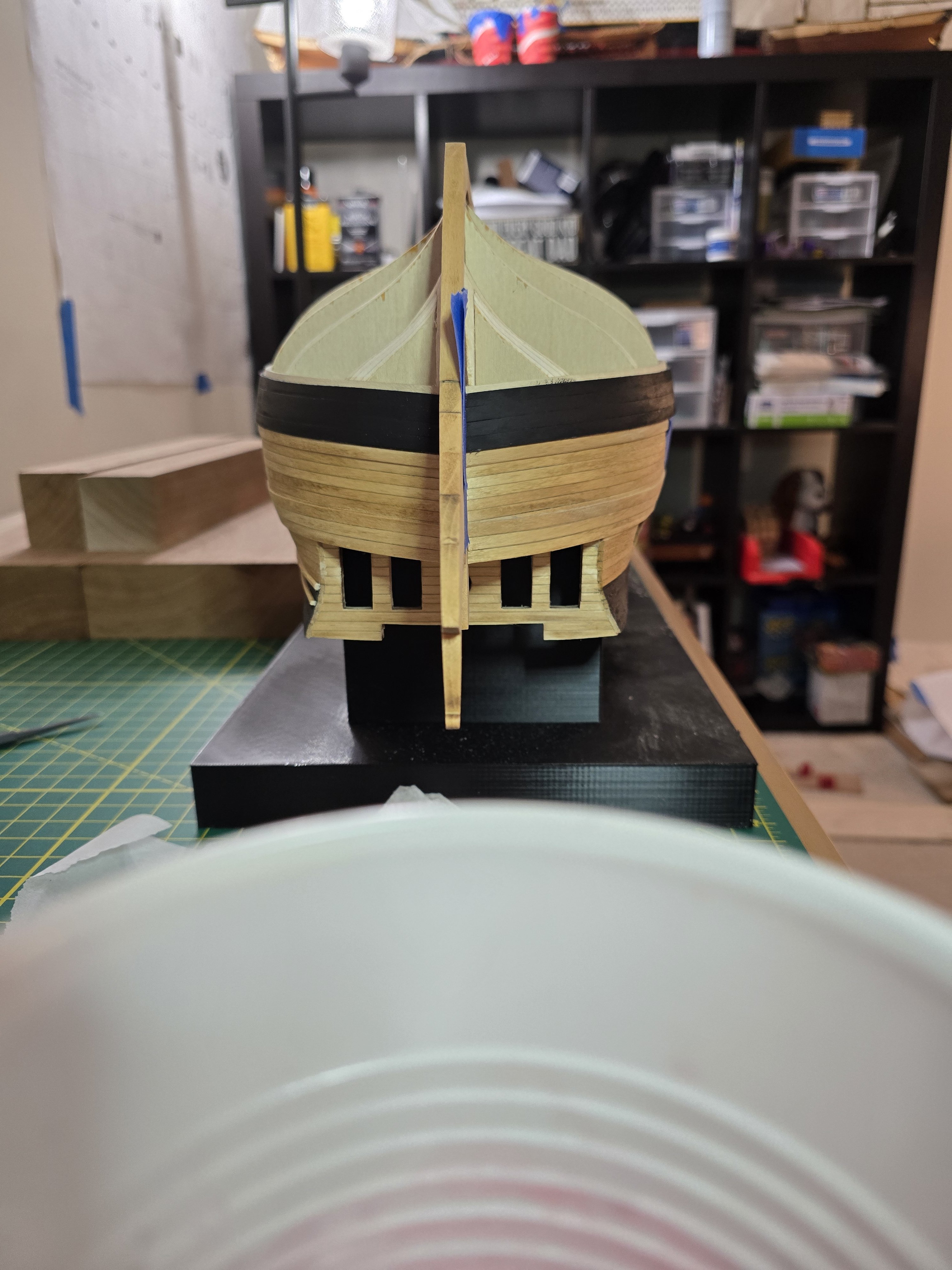
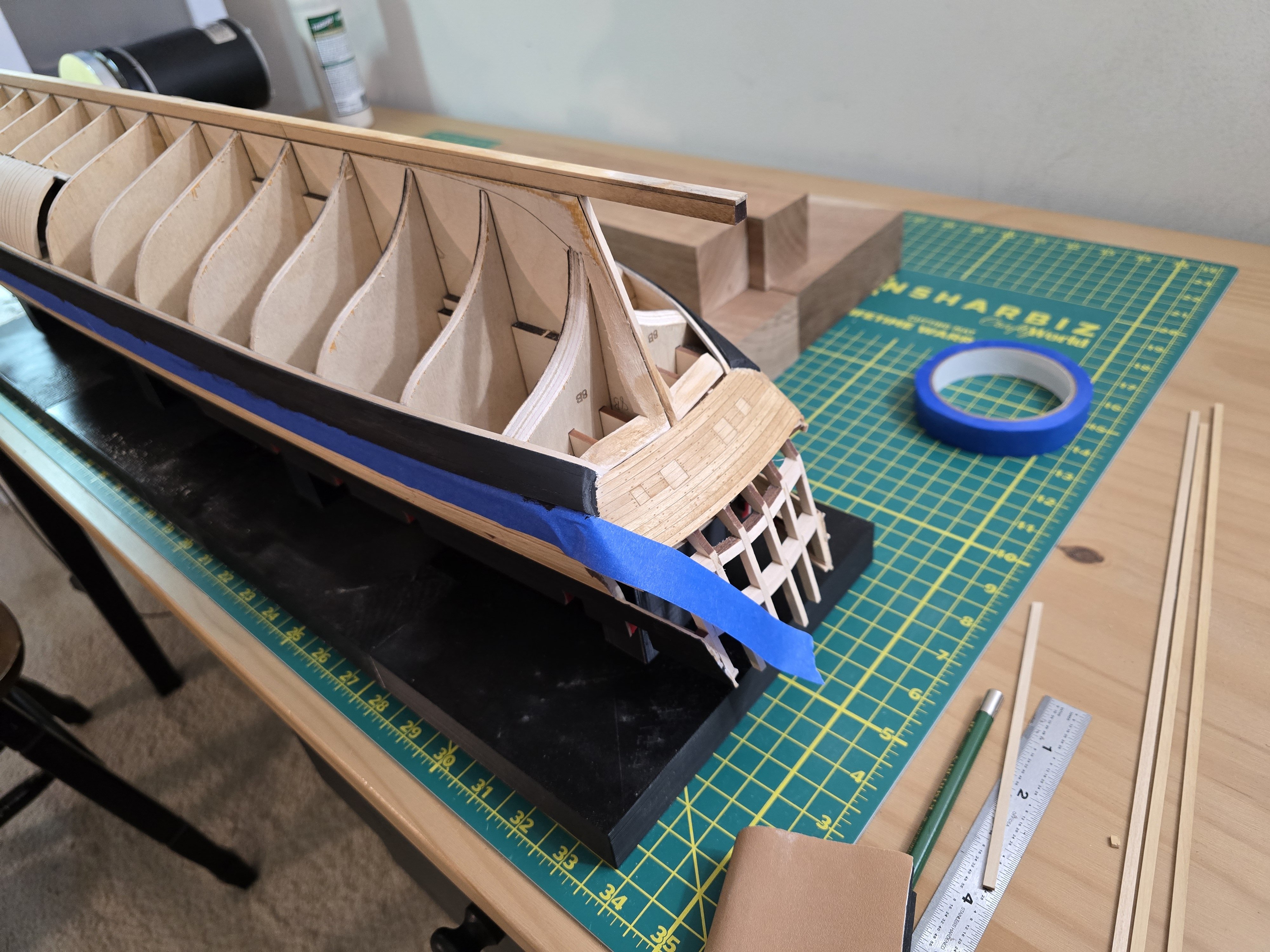
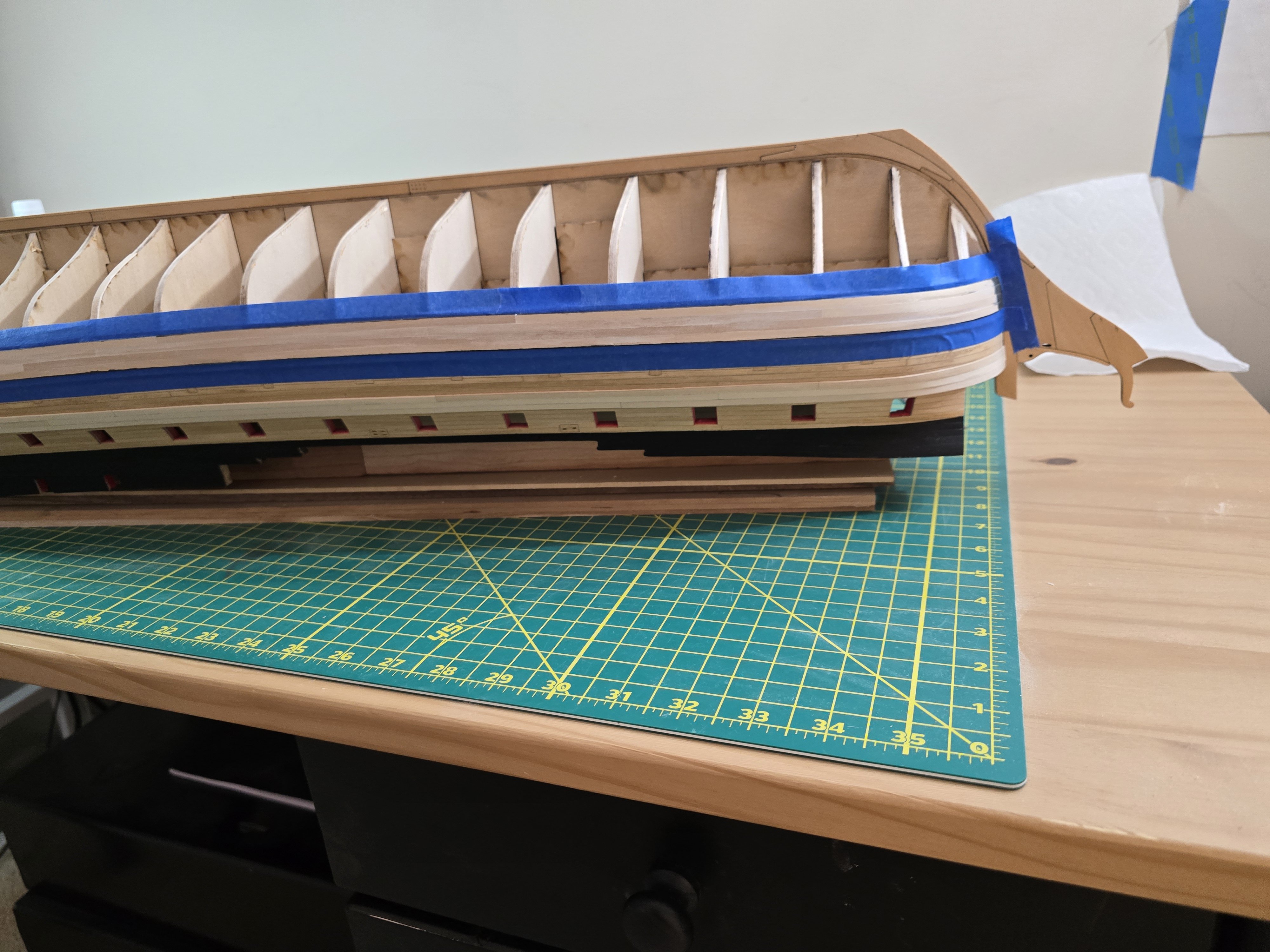
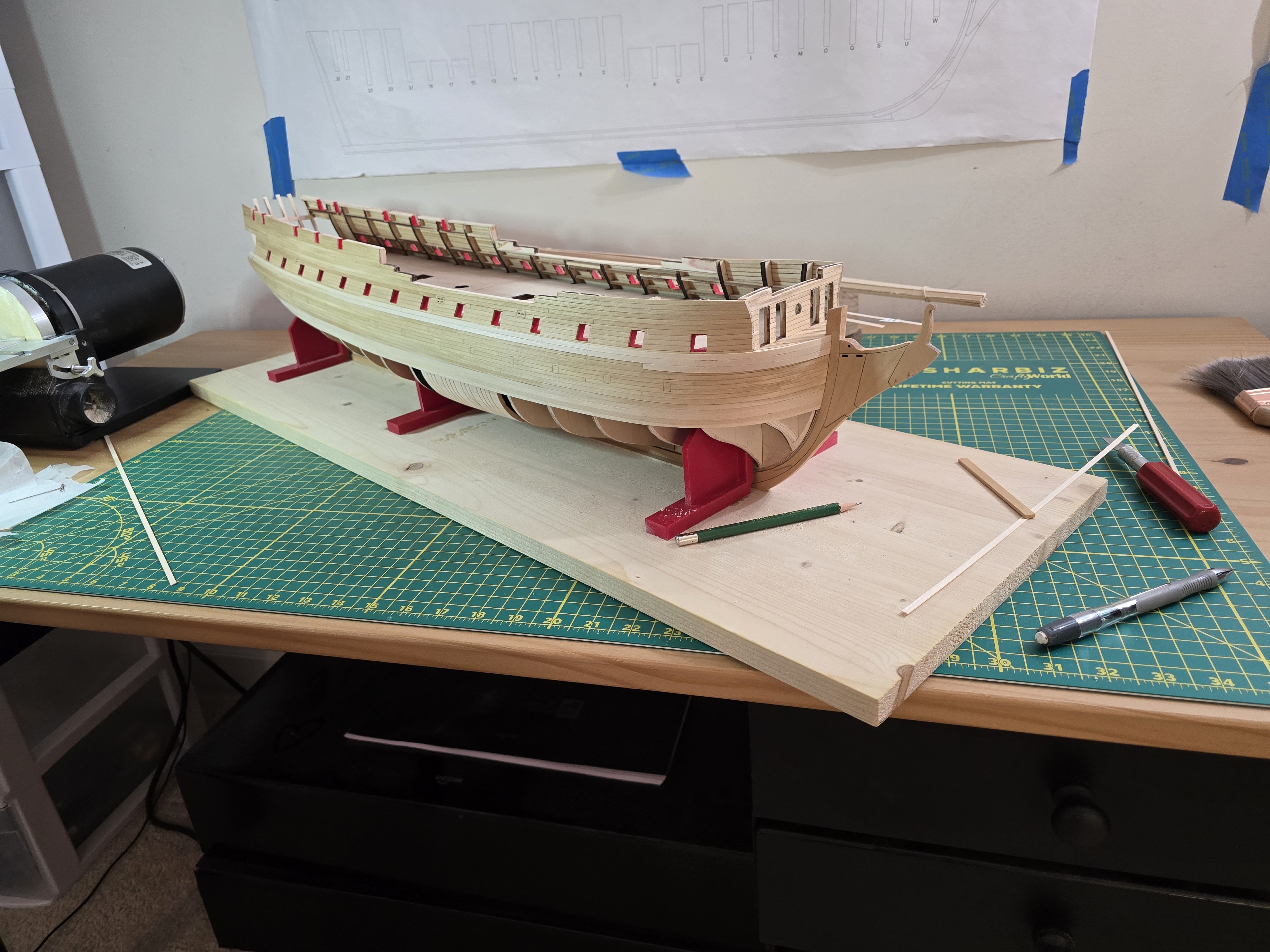
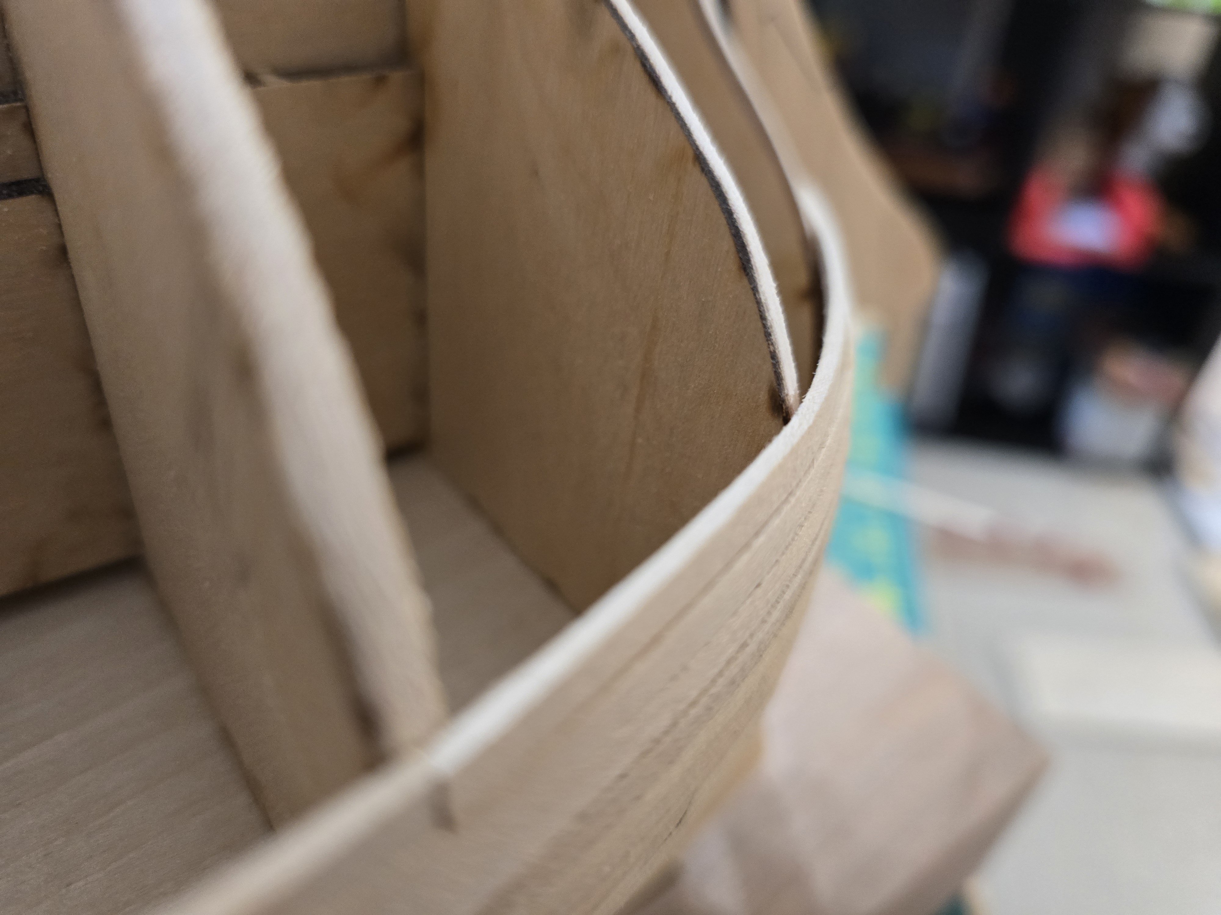
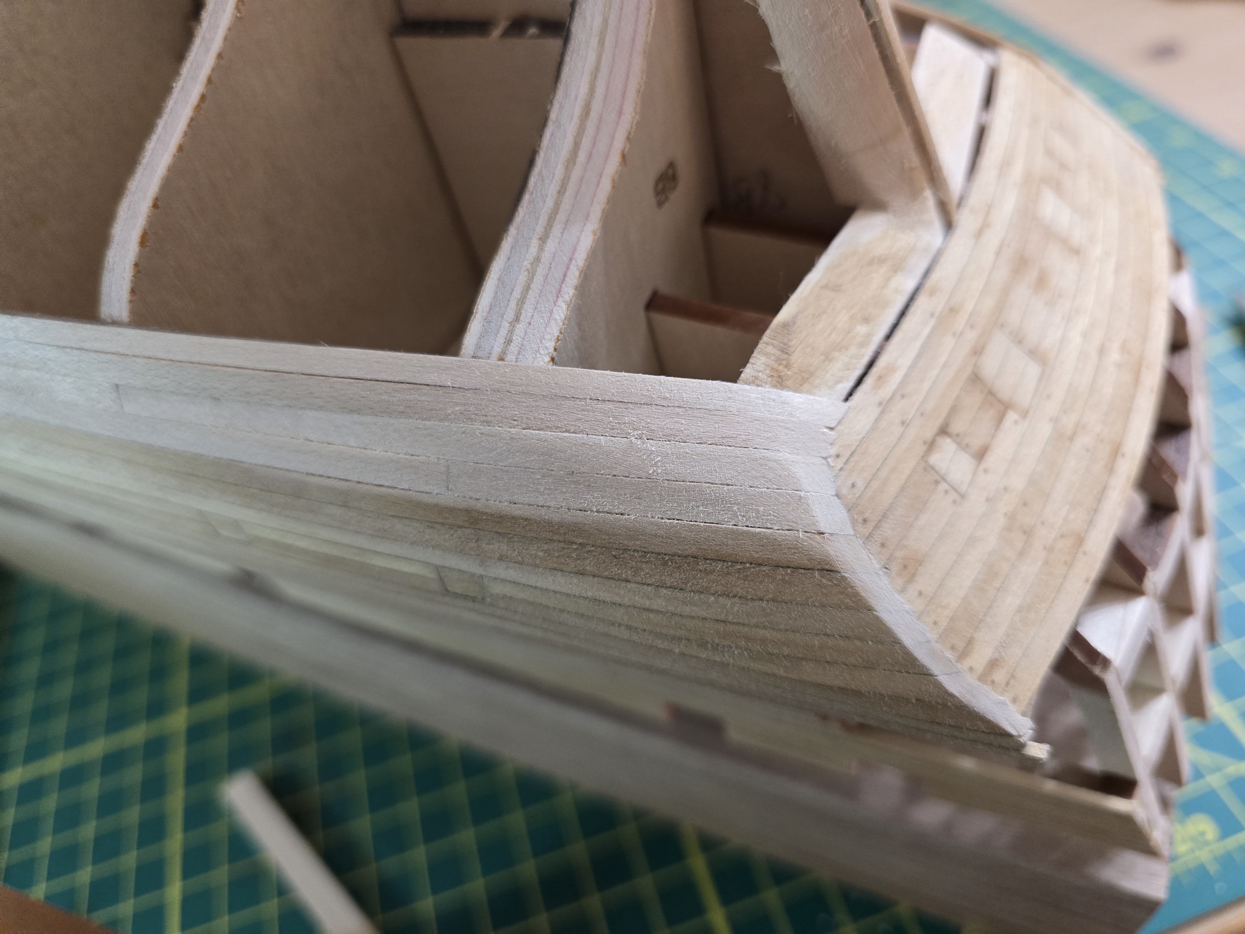
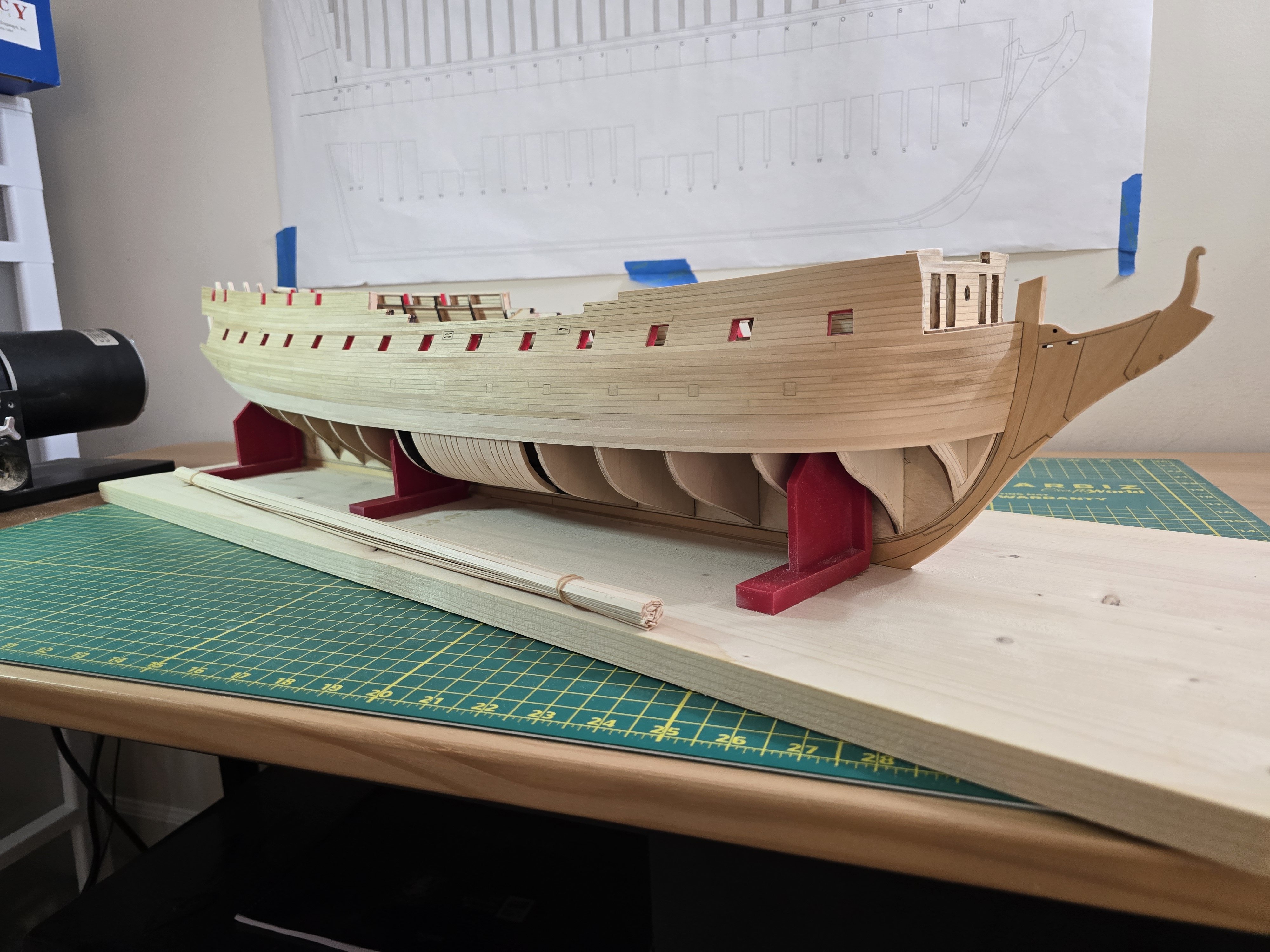
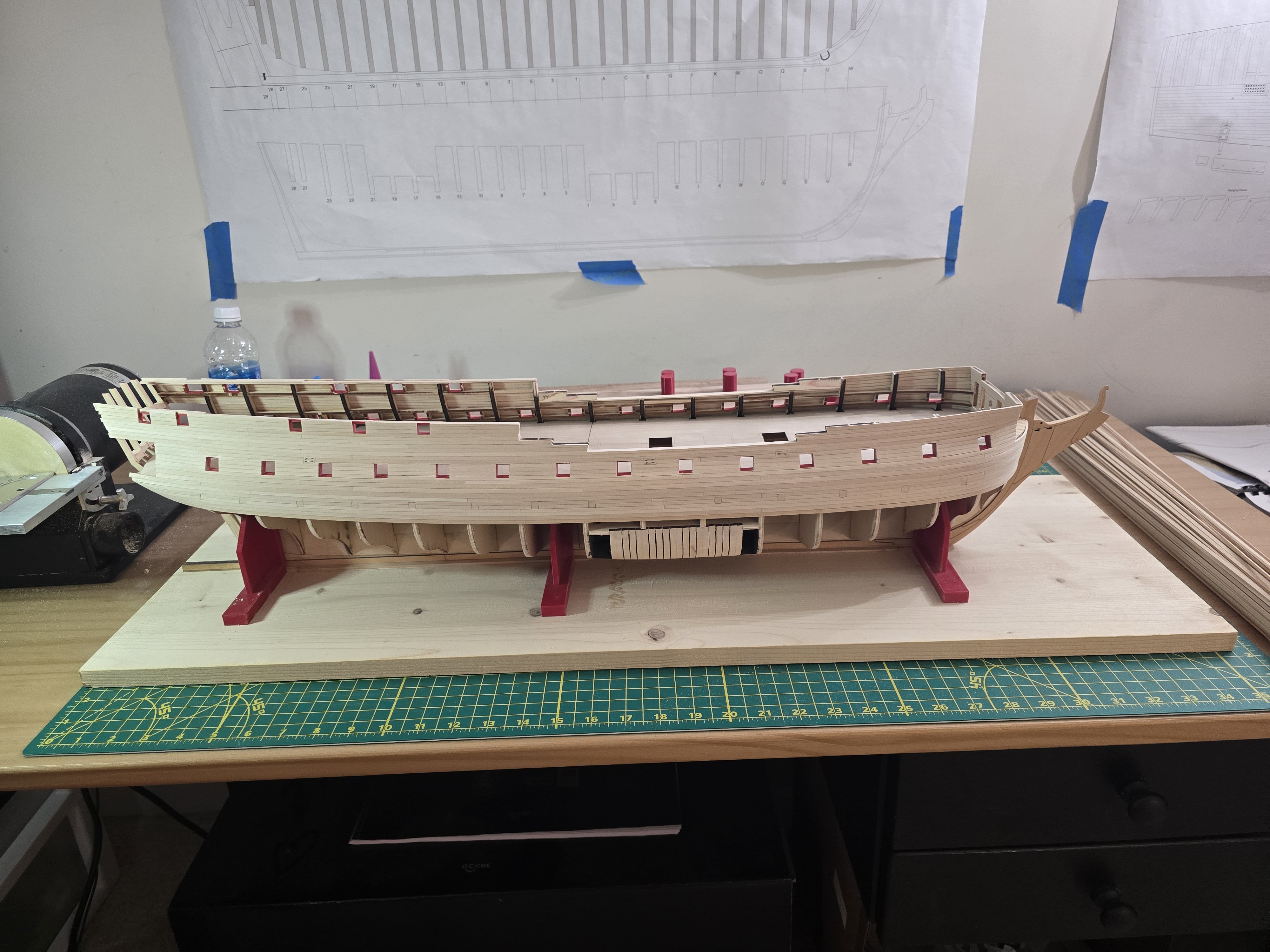
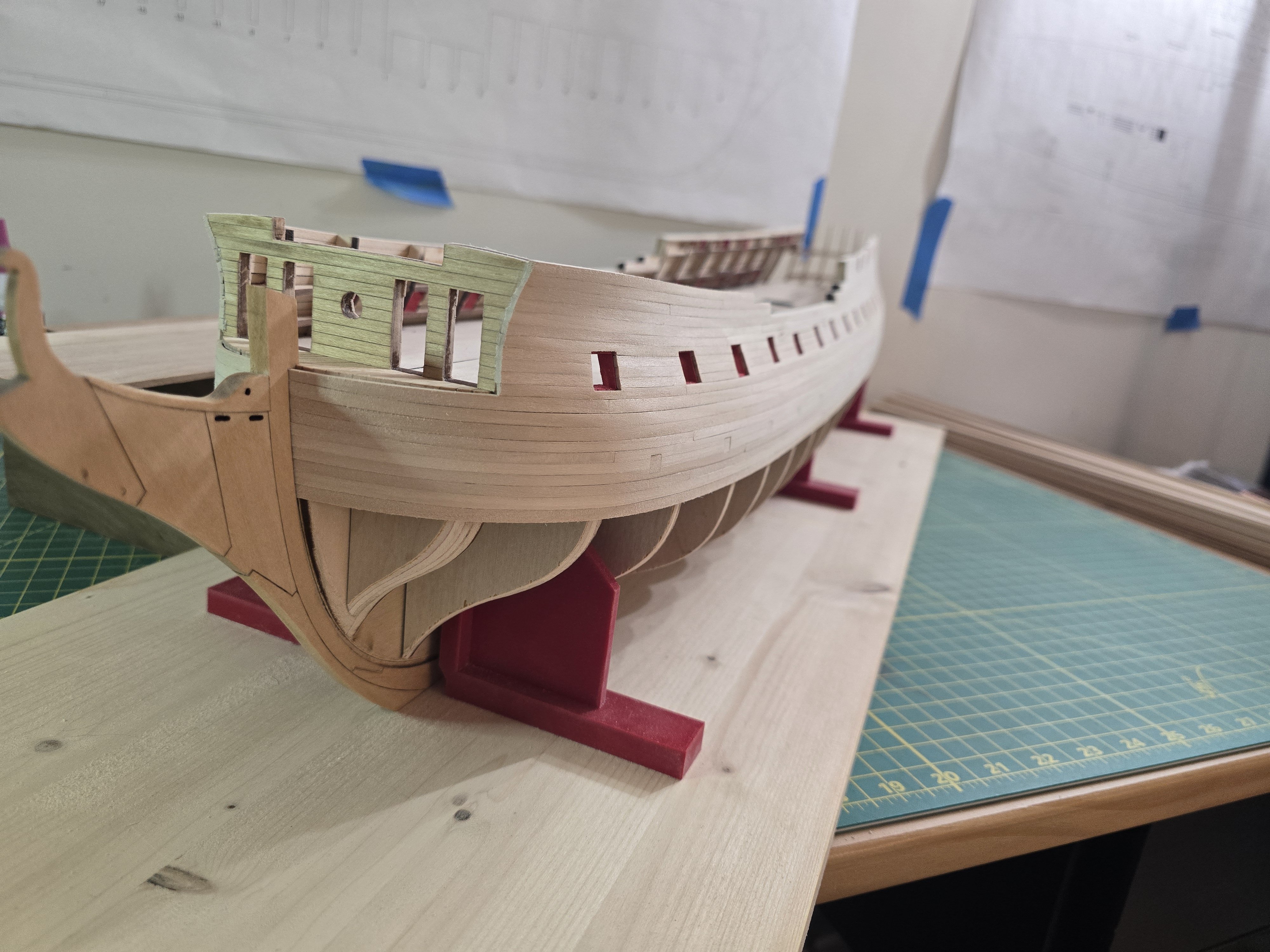
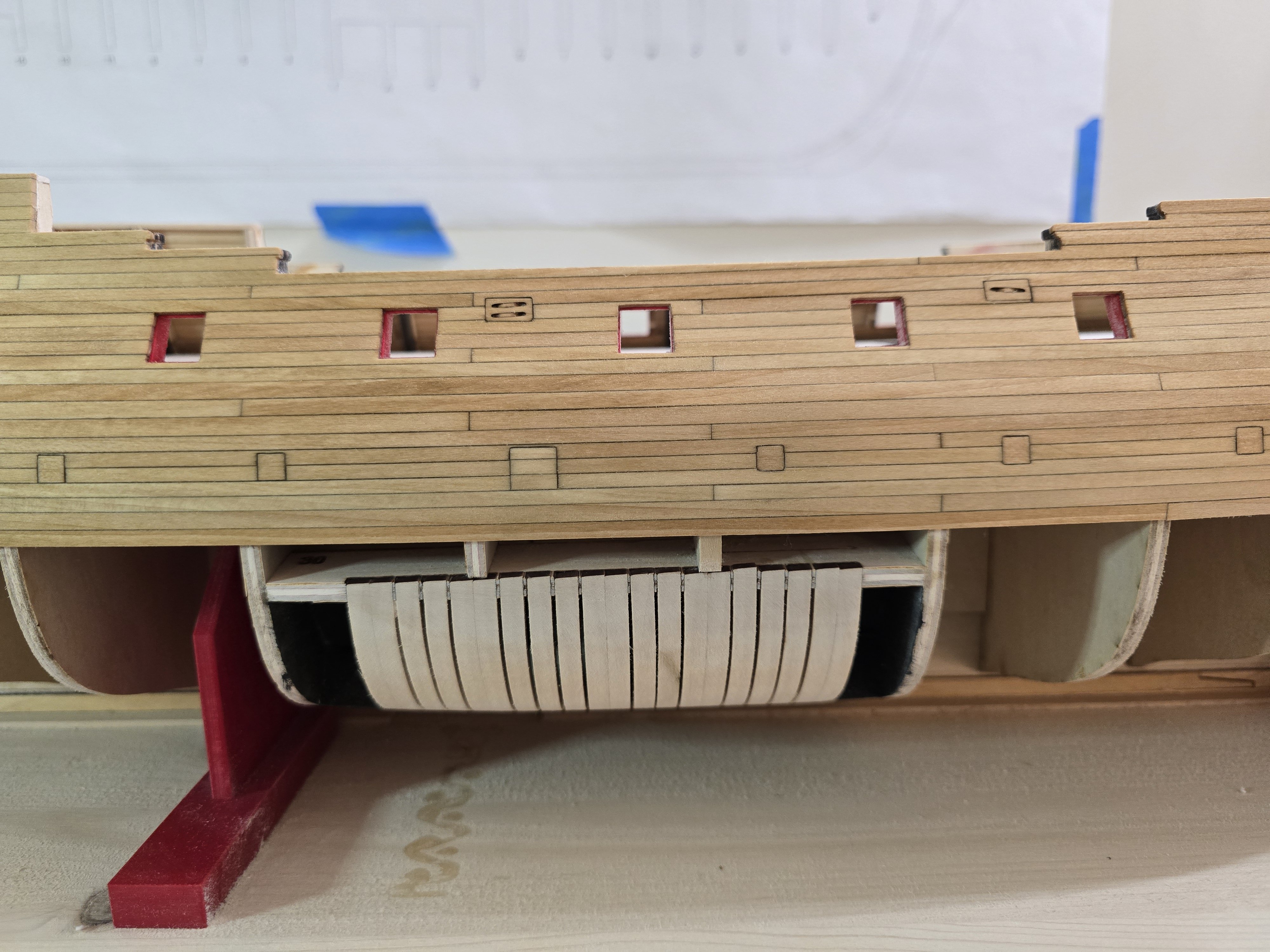
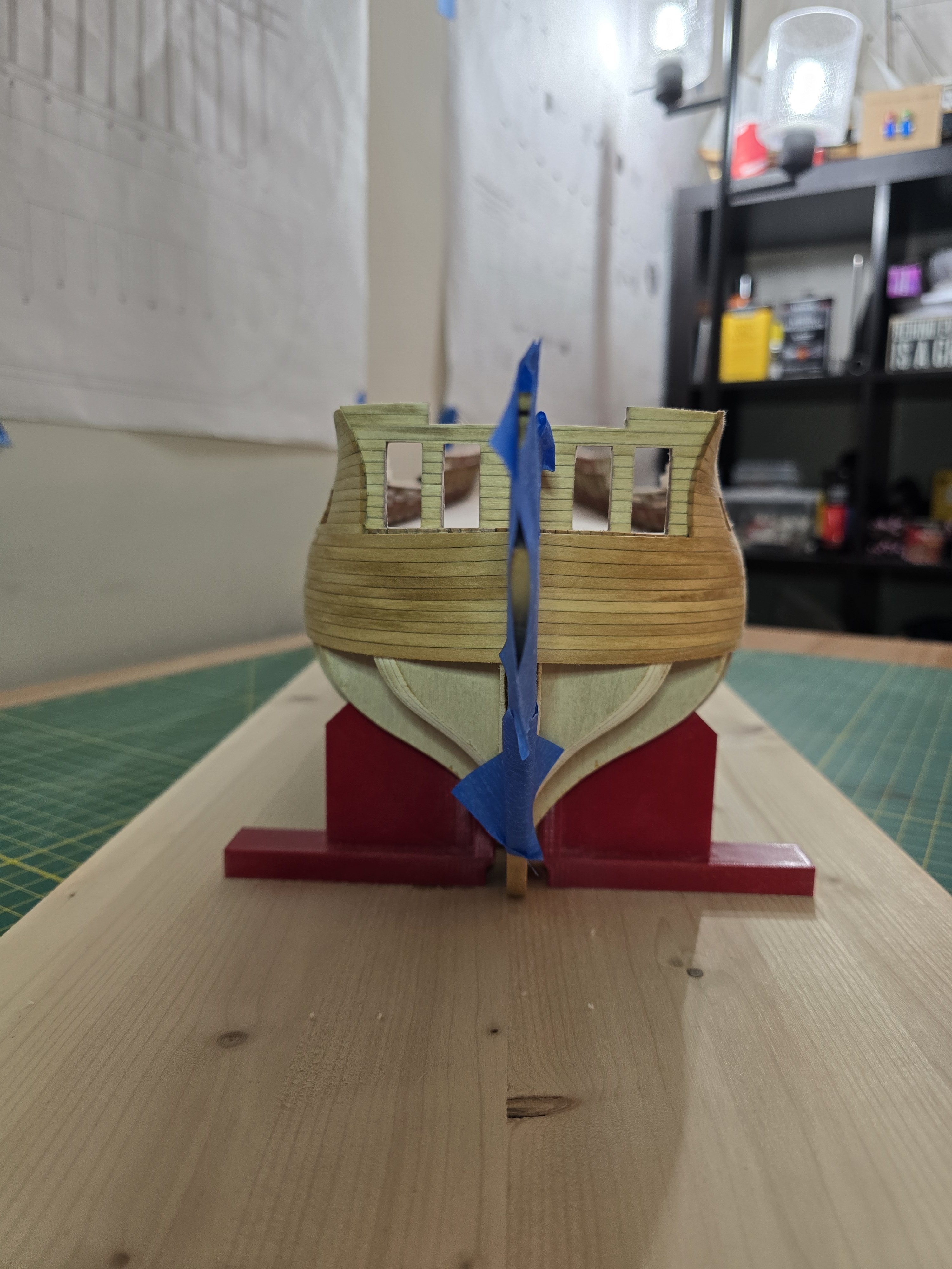
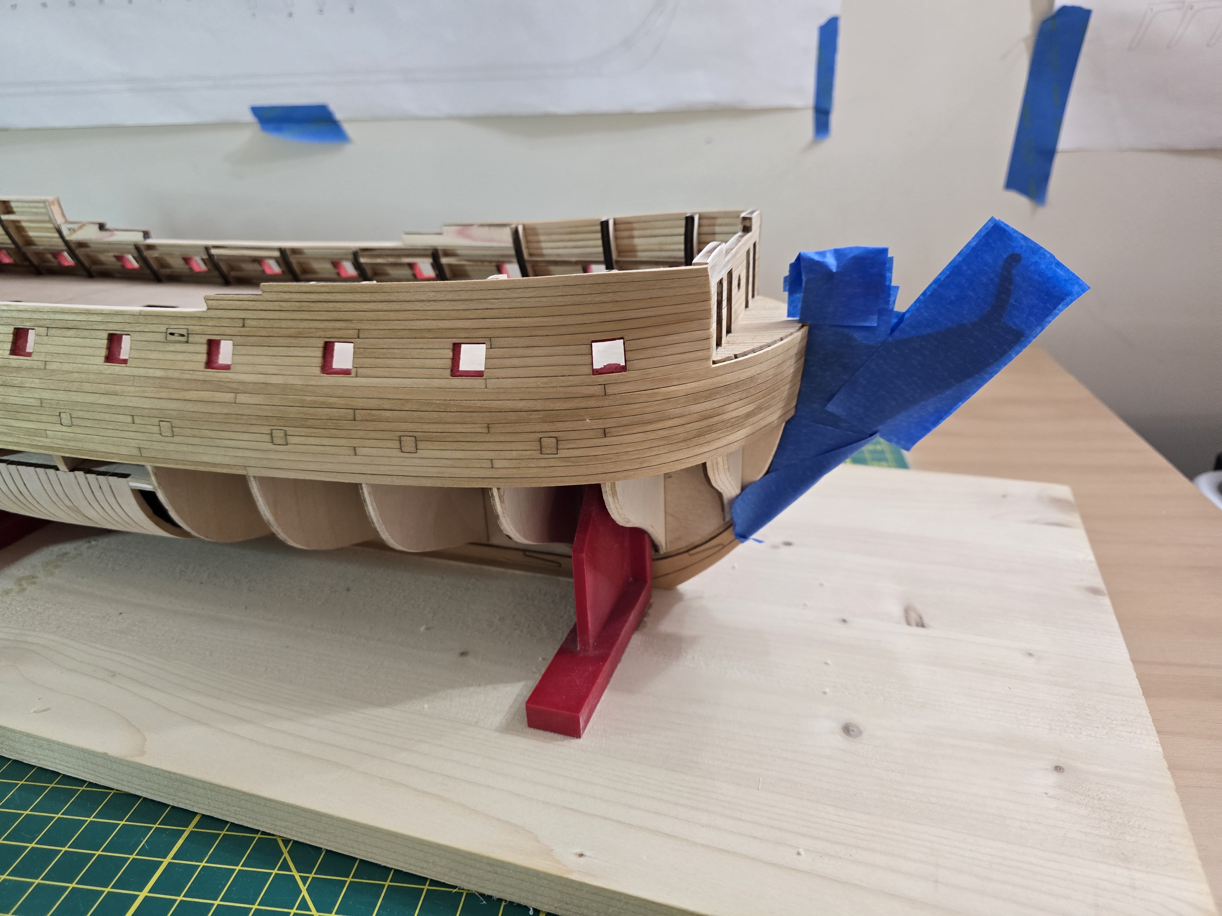
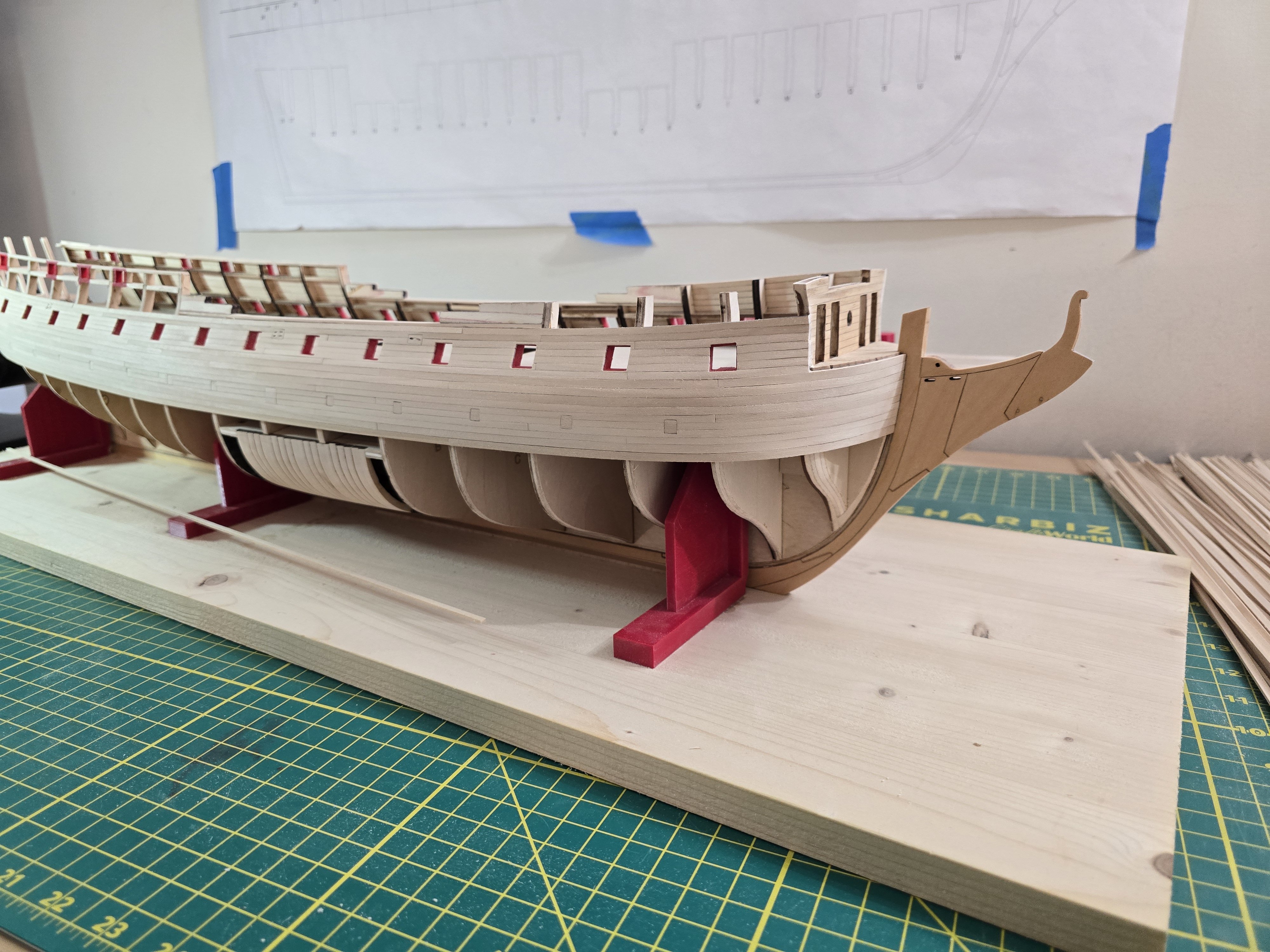
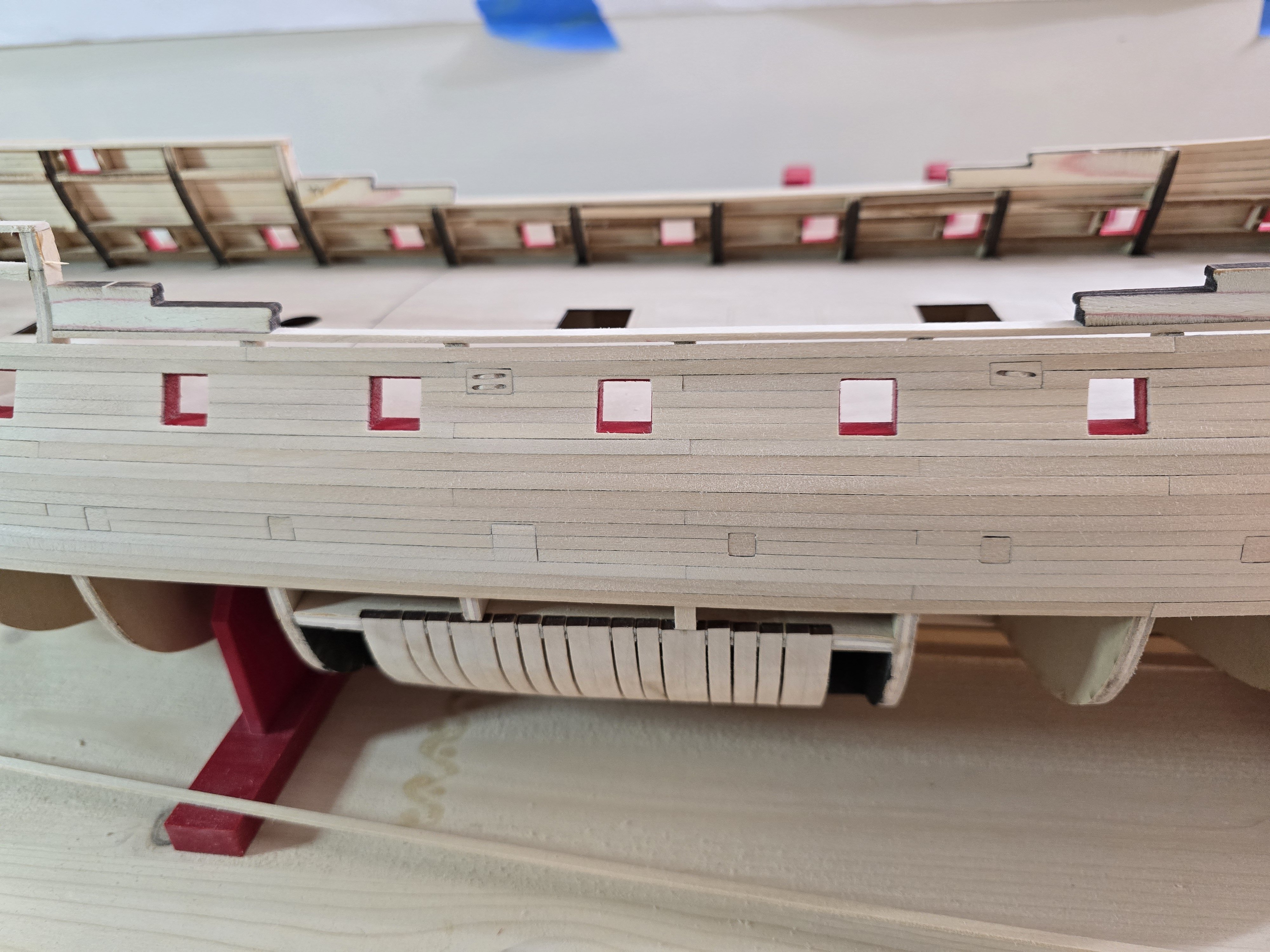
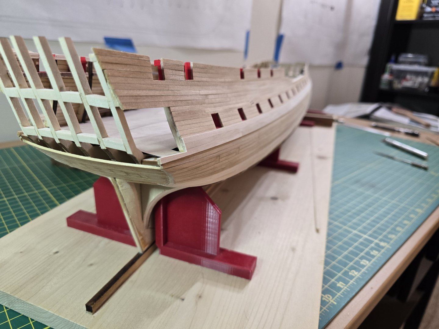
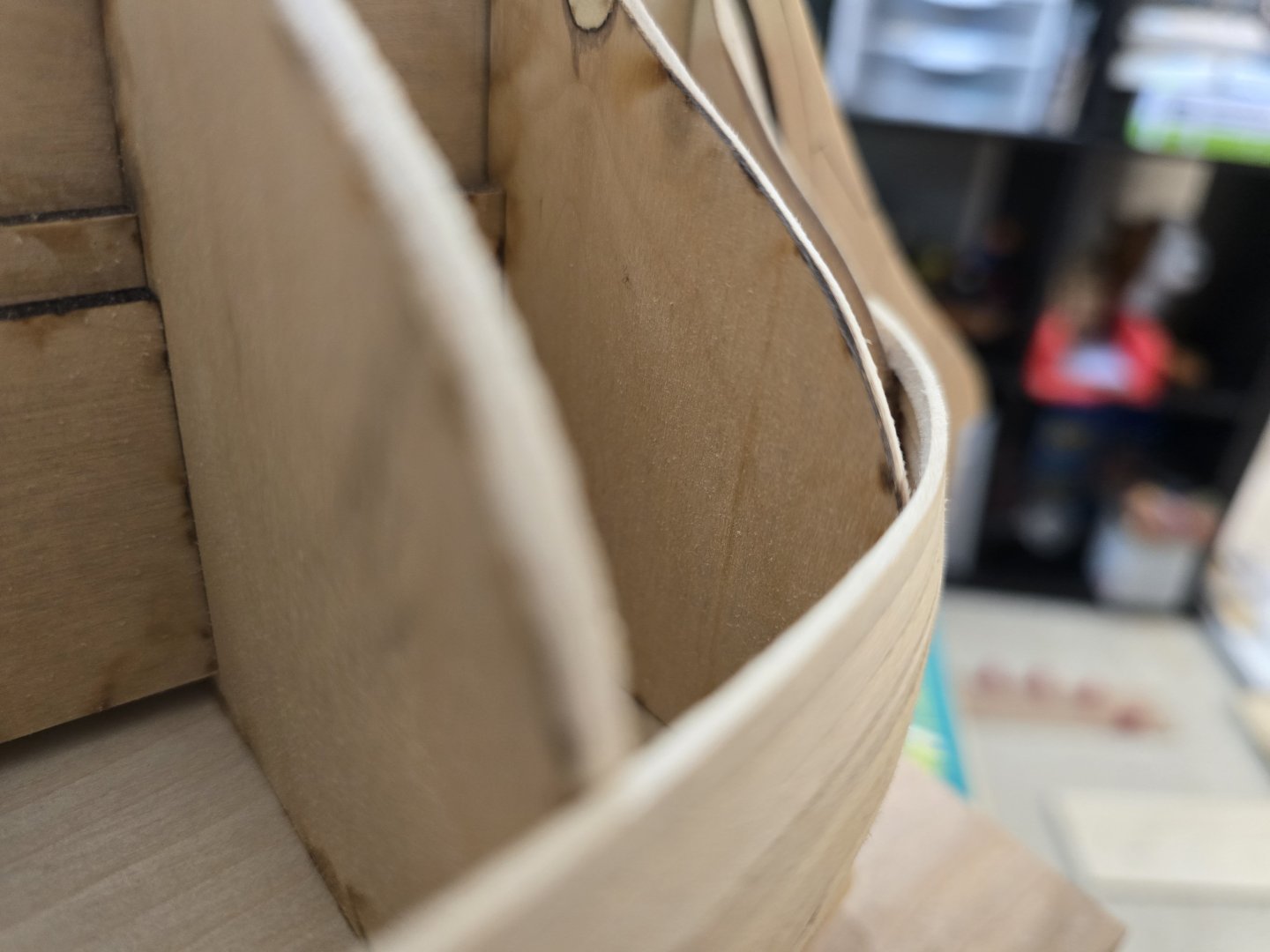
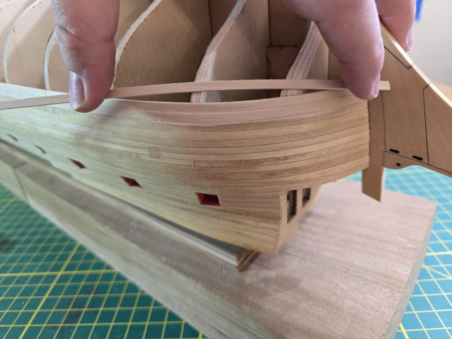
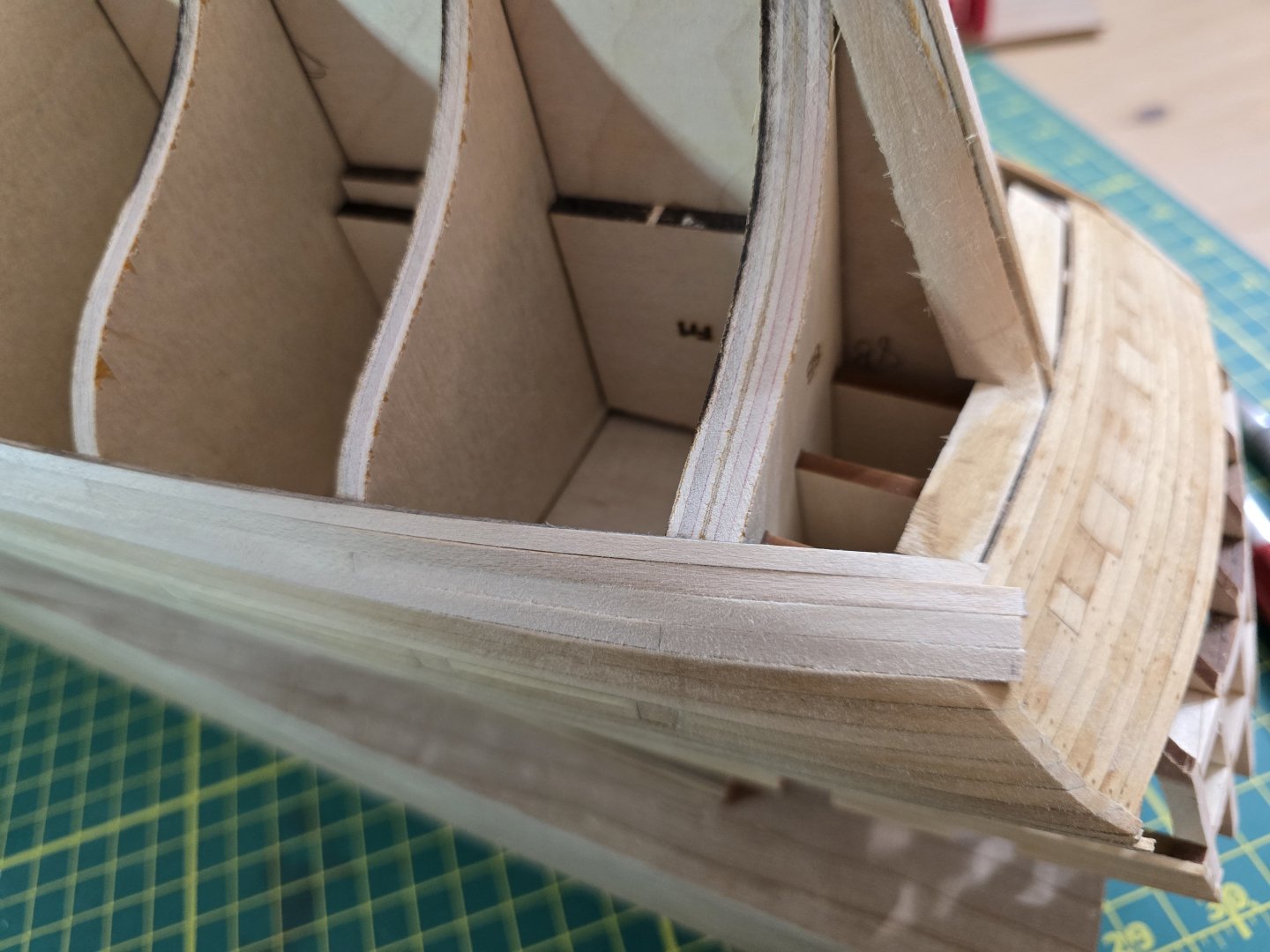
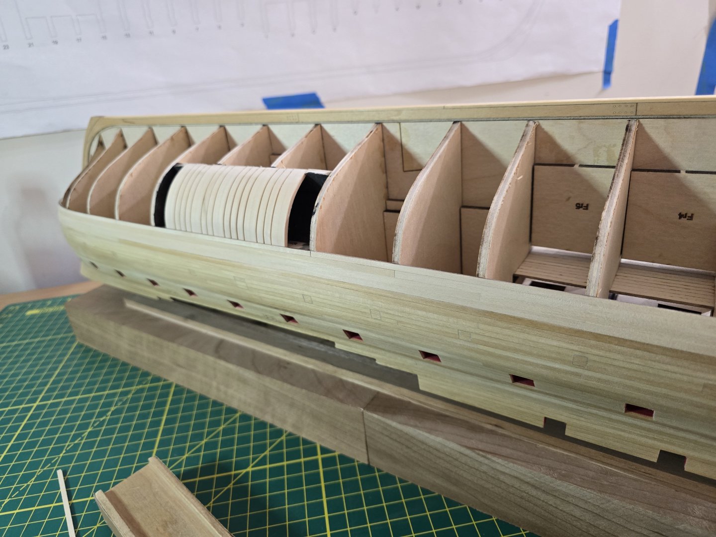
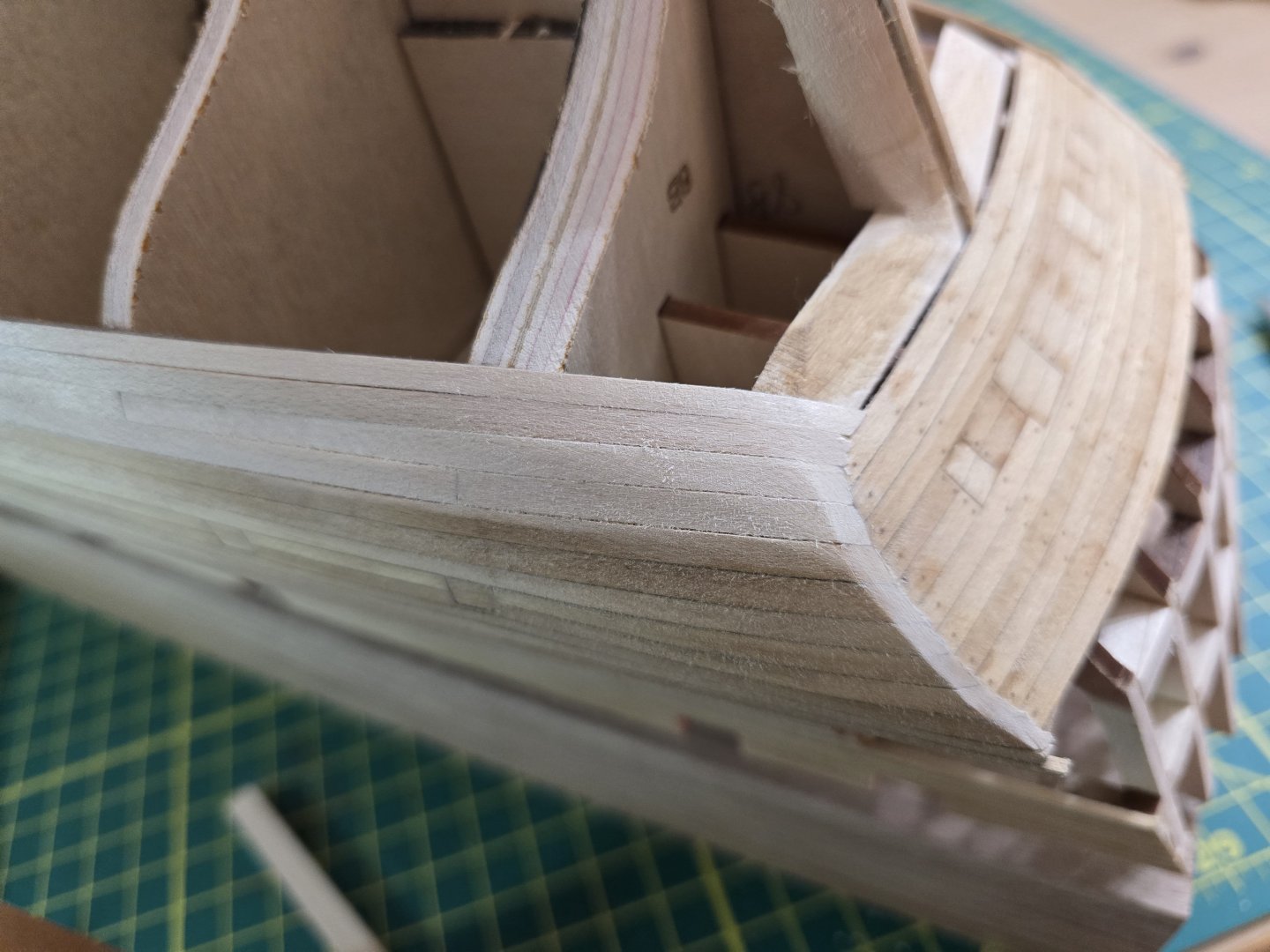
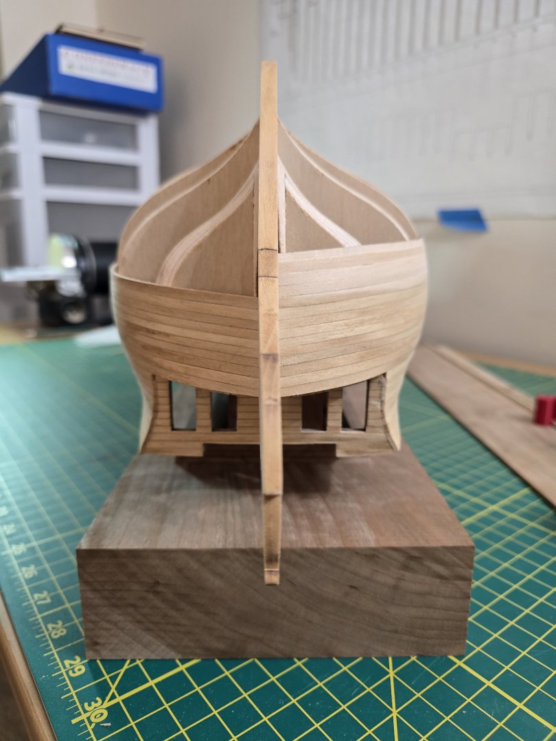
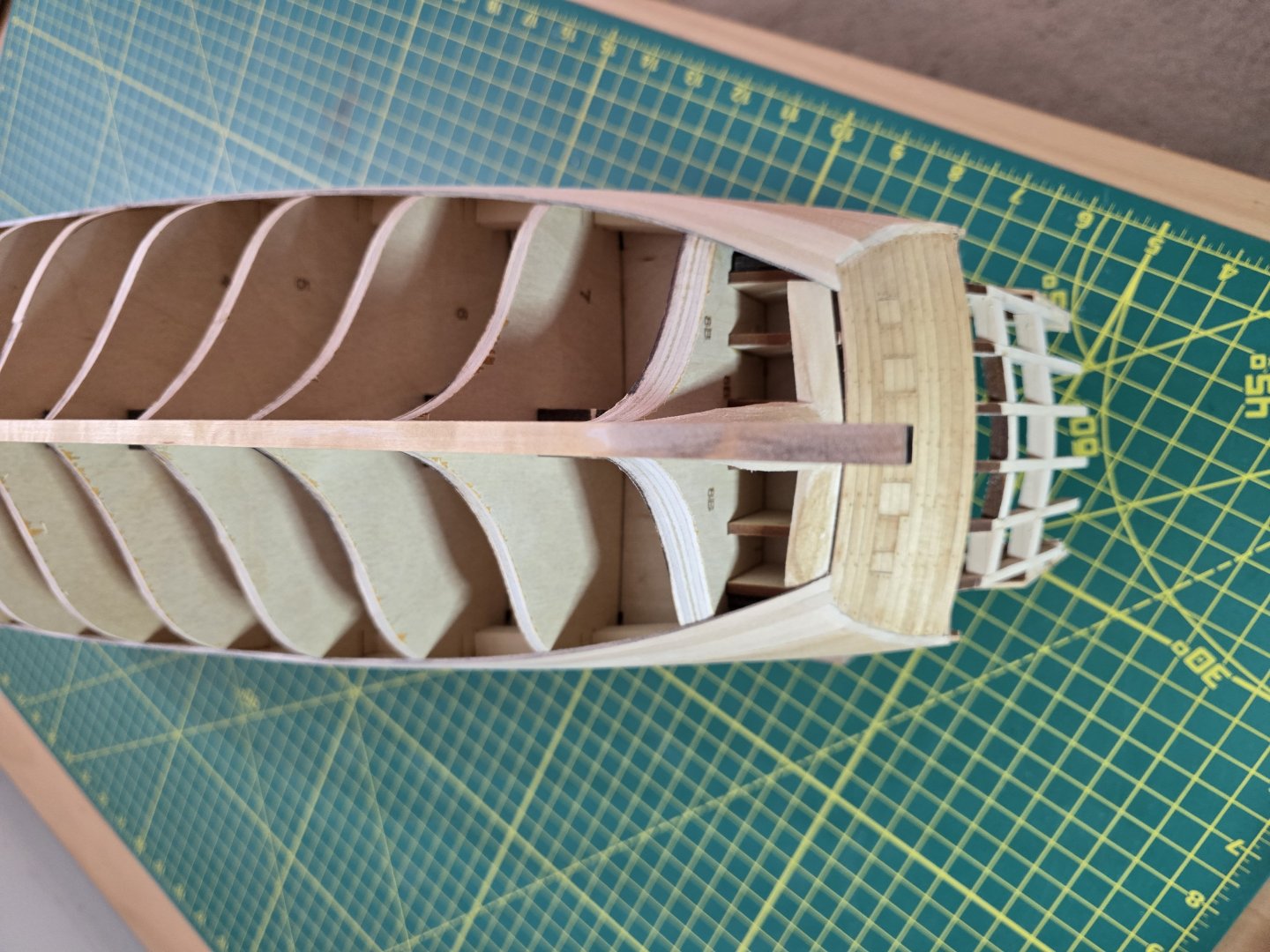
Hey all! I completed the first layer of the wales and the first rows below it. Here are some pics of my progrssion: I hope you can see this in the photo above, but the last wale strake and the strake after that both go under the lower counter. I hope this is correct. I had to start edge bending the planks as i I got lower onto the hull as they would not fit correctly near the bow. This was more prevelant on the last wale strake and the one below that. Here is an example: Hopefully this comes out clear, but if you look at the bulkhead that is in focus, the top plank does not lay flat on the bulkhead at all. Instead it juts out. This causes a massive issue with trying to place the next plank above it as it will cause the next plank to form a gap between both it and the previous row of planks. No amount of sanding can fix this issue. To fix this, I removed the badly placed plank. I then laid a new plank on top as shown below. I then marked where the center of the biggest gap was on the new strake and edge bent it using the mark as the center point. After placing it back onto the model, the curve now looks like this: Notice the top of the plank sits against the bulkhead. Whew! I continued and finished both sides. These next pics I thought was just cool because it shows off what we will never see again as we continue to plank. The underside of the gundeck and bulkheads and supports. Finally, here are a few pics of it placed upright. I hope it looks alright! Lastly, I need to say I ran out of 5/32" x 1/16" strips! I literally have 1 full strip left and some left overs. I did not throw any out. I used all of them that were provided in the kit. So I have contacted Model Shipways ( Model Expo) to see if I can get 10 more strips so I can finish the second layer of the wales. I did fill out their ordering form using their instructions. We shall see! So what I CAN place on next are the 5/32" x 1/32" strips used for the channel wales and black strake. So I will start on that soon while I wait for the new strips. Thanks all! Jeff


-
Those gunports look really good. Cutting out the top of the gunports isn't easy and I'm glad you took your time with it. Well done! Jeff
- 21 replies
-
- 1
-

-
- Santisima Trinidad
- OcCre
- (and 2 more)
-
@glbarlow Thank you for your advice about sanding the tops of th bulkheads. What I actually ended up doing was to sand down the boxwood gunport frames that protruded higher than the bulkheads. I sanded these at an angle to give more material to the next adjacent bulkhead. I just didn't want them protruding and somehow getting stuck on something. Because knowing me, that would happen! I looked at your build log and you have done a fantastic job! I'm looking at your placement of the wales too to help gadge if mine are alright. Thank you for the advice! Jeff
-
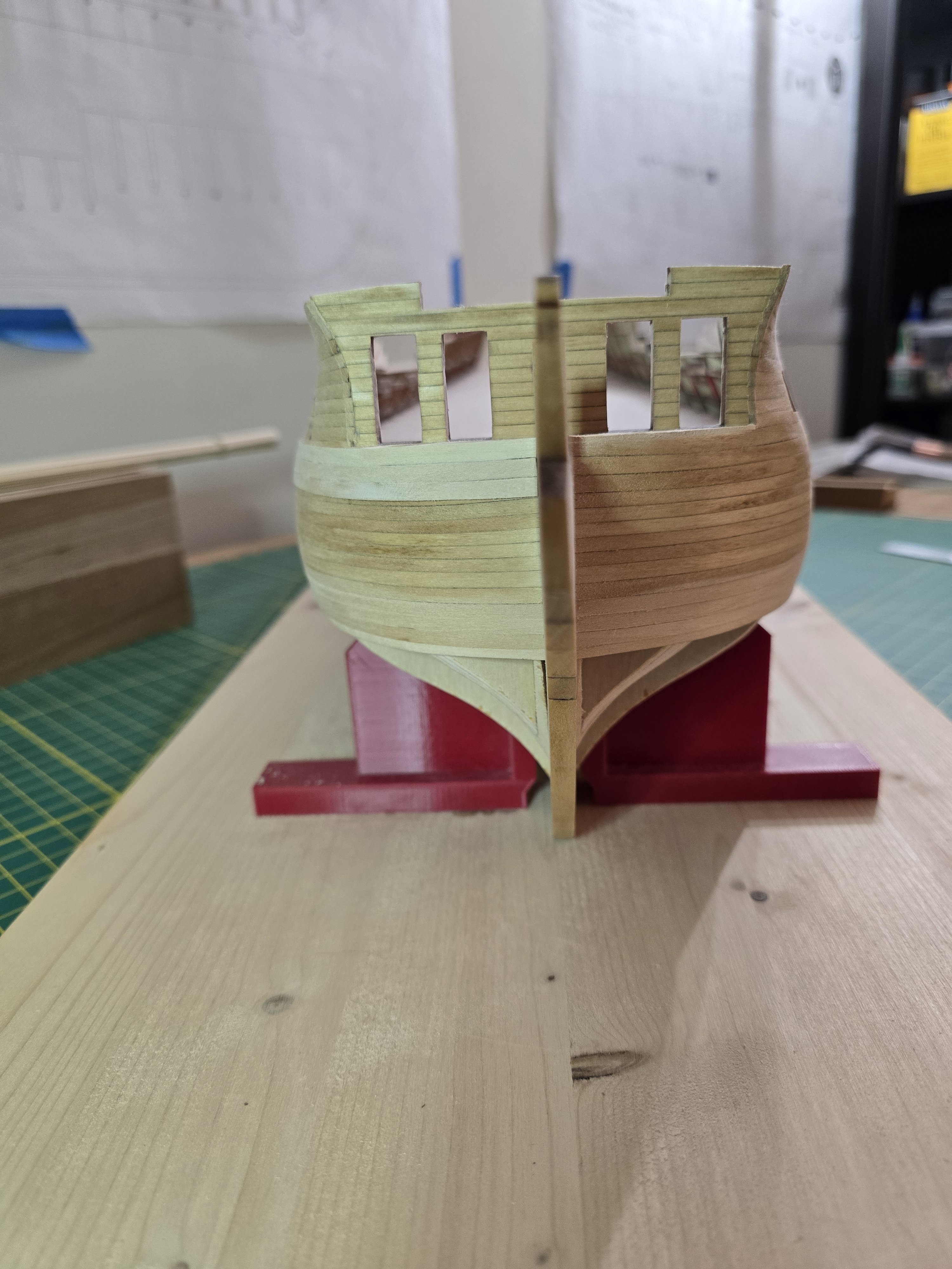
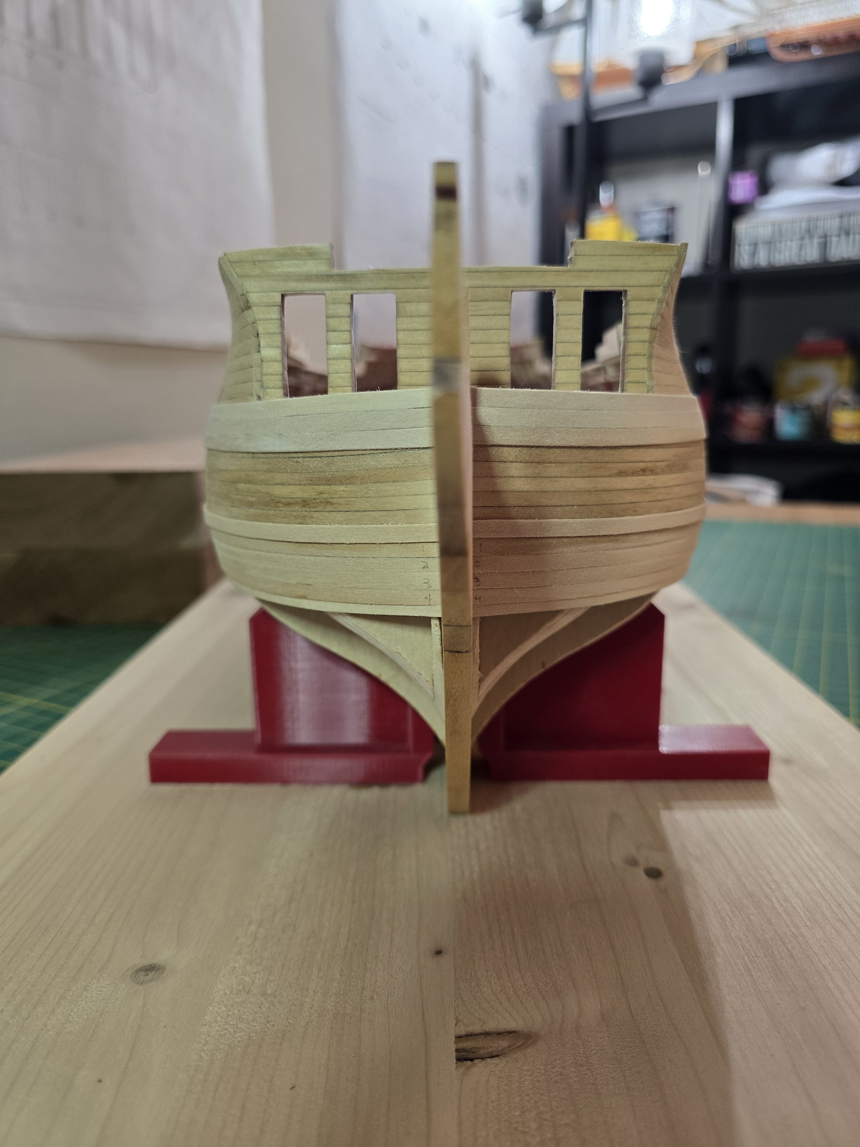
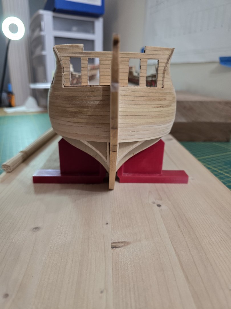
@Erik W Thank you very much for linking to your log. You have done a fantastic job on your planking! The seams really came out well and the square tuck looks really good! After comparing, I think mine looks ok but I feel maybe not quite enough curve at the bow. But maybe it is enough. Maybe I'm being too much of a nitpick. Concerning the stern, I might make a copy of the stern from the plans and tape it on the model to see if I think there is too much of a curve. I'll also look through your and others build logs to conduct more comparisons of the stern and bow. The last thing I want is too much of a curve on either. That would mess up quite a bit of the planking. Thank you for the advice Erik! Jeff
-
Hey all! I need another set of eyes. The first plank is the most important to lay the rest of the planks. I have placed the first wale strakes on one side of the hull and would like to ask of you guys think if looks like it's in the correct place. If it looks good, I'll continue with the other side's first strakes so I can make sure they look as even as possible. If not, I don't mind taking these 2 pieces off and adjusting. Fixing the planking now will save a lot of headaches later. Thanks!! Jeff Houston


-
Ross, you have done amazing work! It looks fantastic! I really like how the decking turned out. Nicely done! Jeff
- 21 replies
-
- 1
-
-
- Santisima Trinidad
- OcCre
- (and 2 more)
-
Thank you Ronald! I agree I really like how the edges are turning out! I looked at it again today and noticed the stain has lightened some. I think that's great! Because later, I will need to add in all those tree nails and stain/varnished again. I was a little worried that if I stained again, it would be too dark. I'm going to take a break from her for a few days to allow the stain/varnished to finish drying and stop smelling. In the meantime, I'll be working on my Cheerful build starting tomorrow. Going to start planking the first layer of the wales! Thanks all! Jeff
-
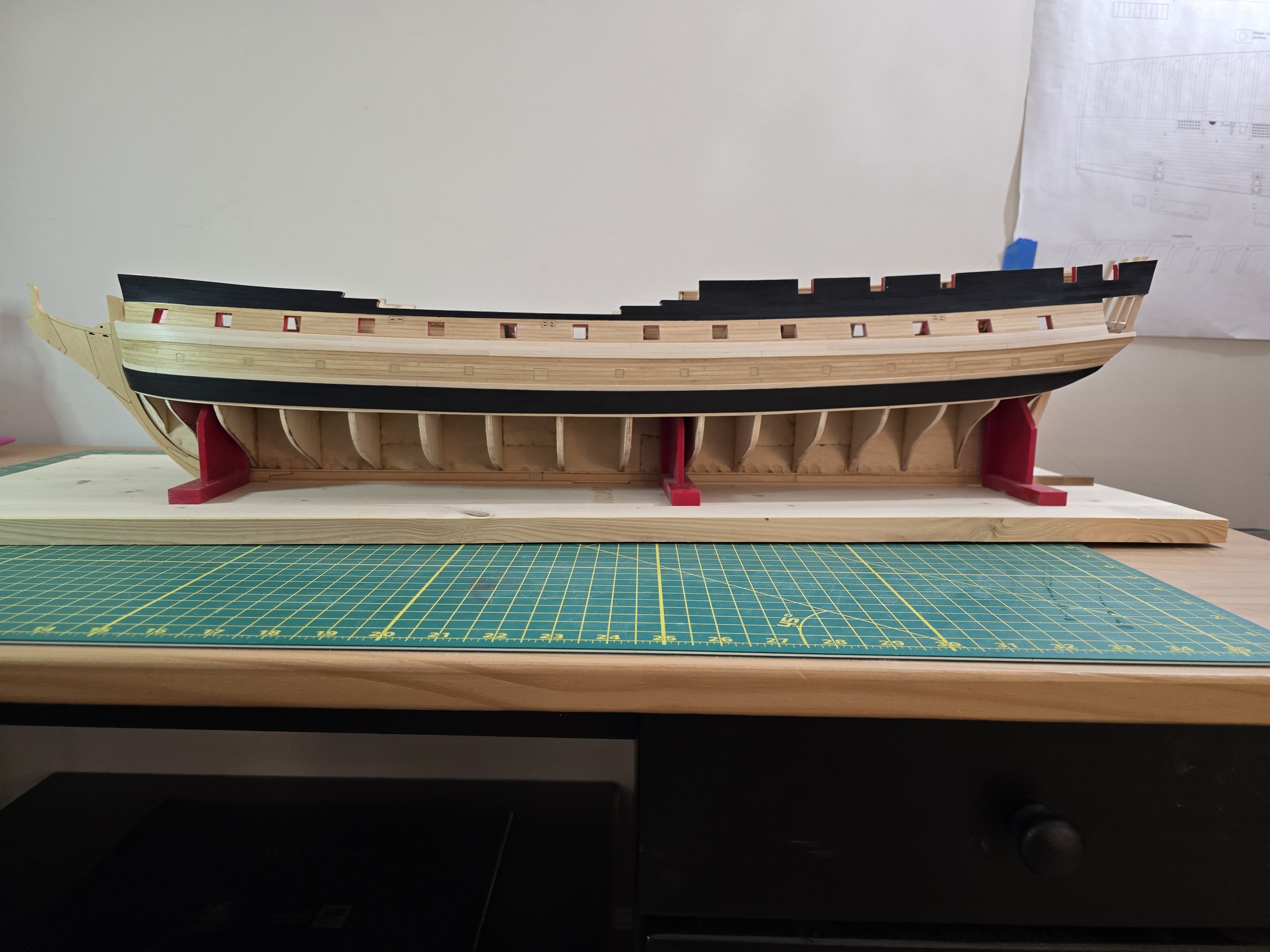
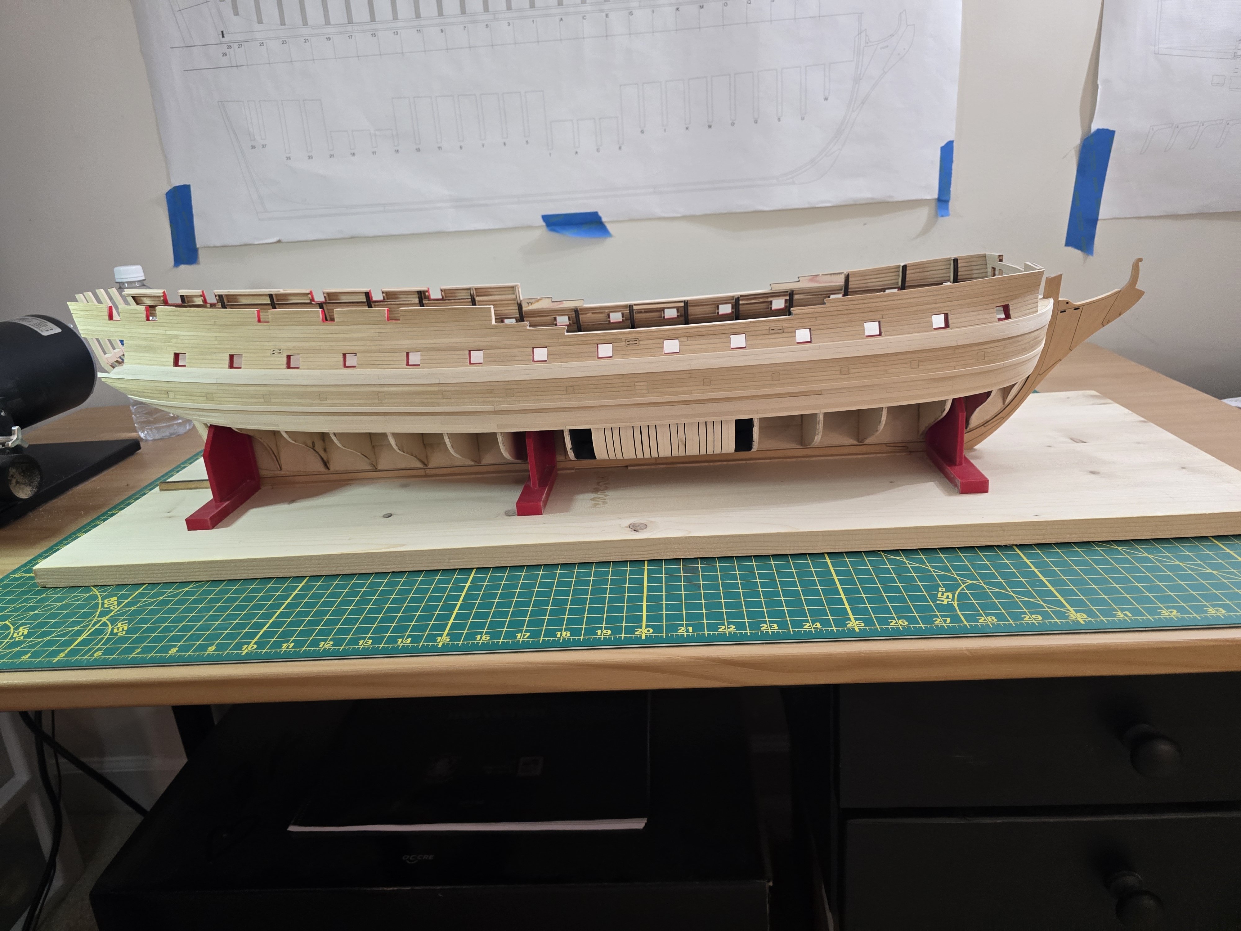
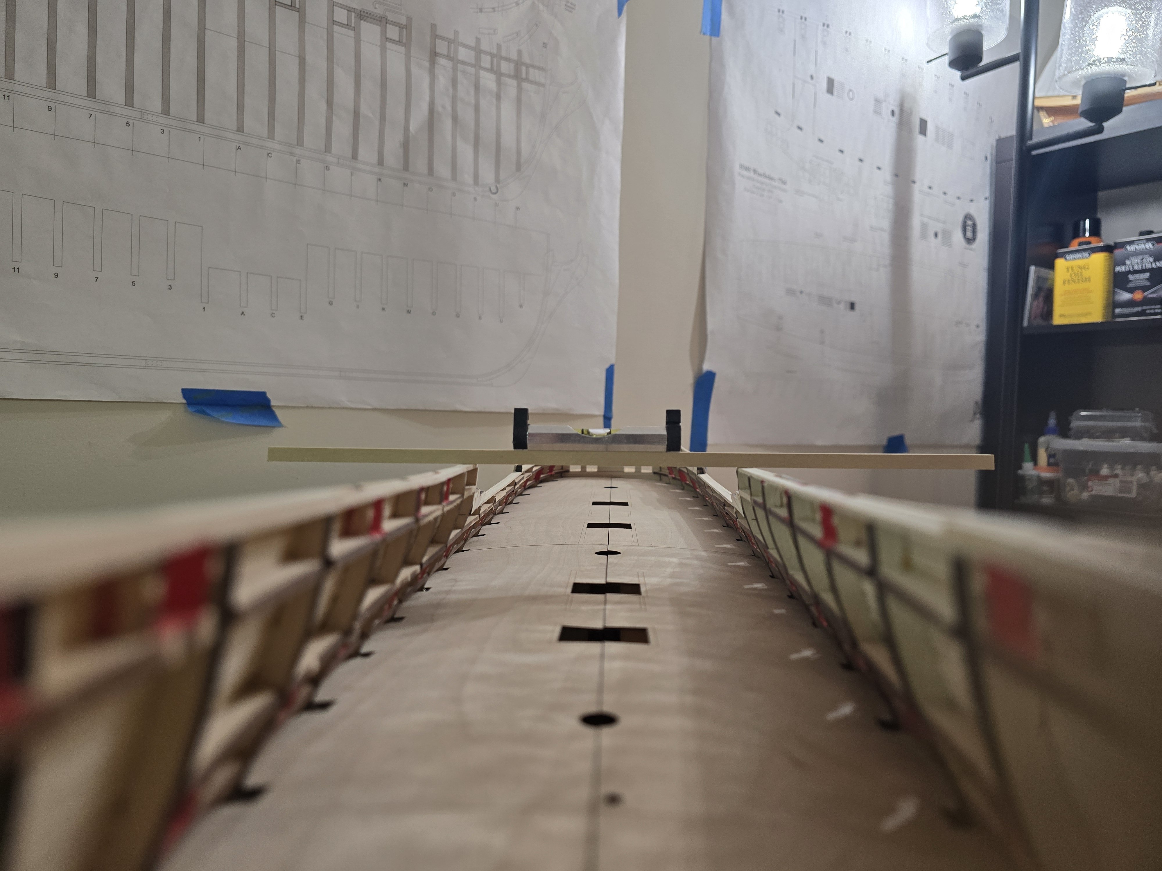
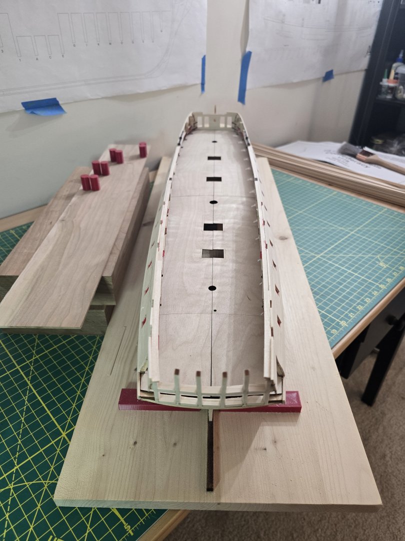
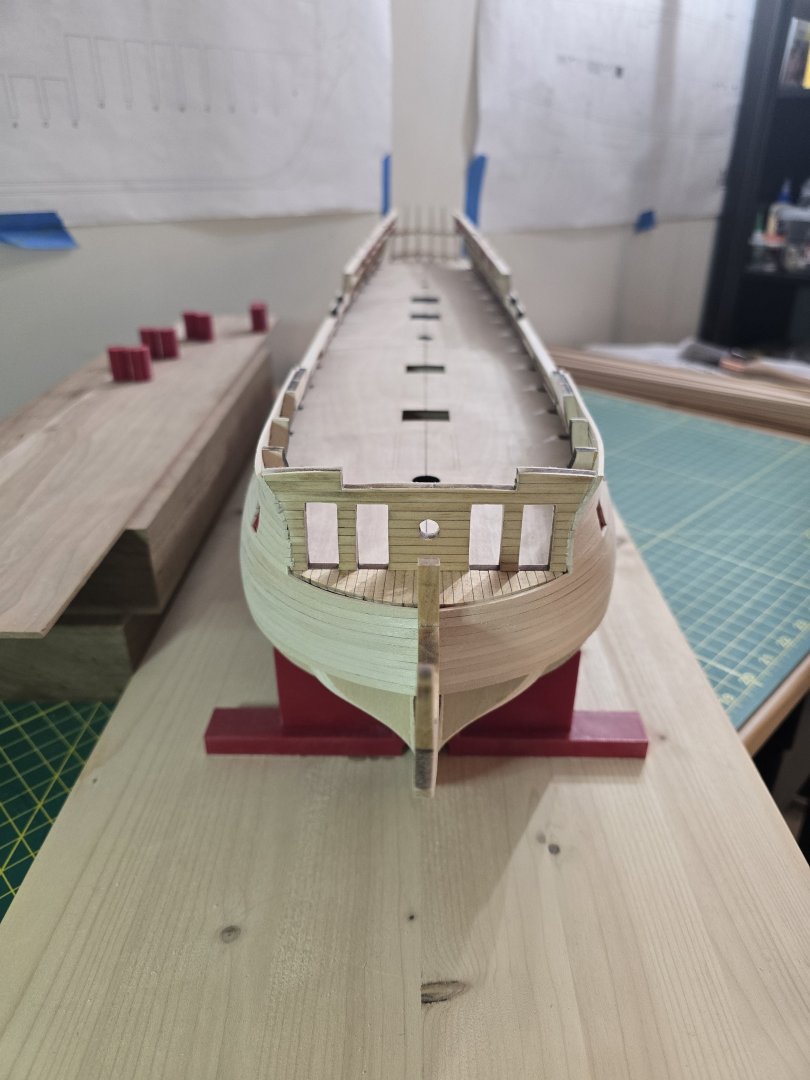
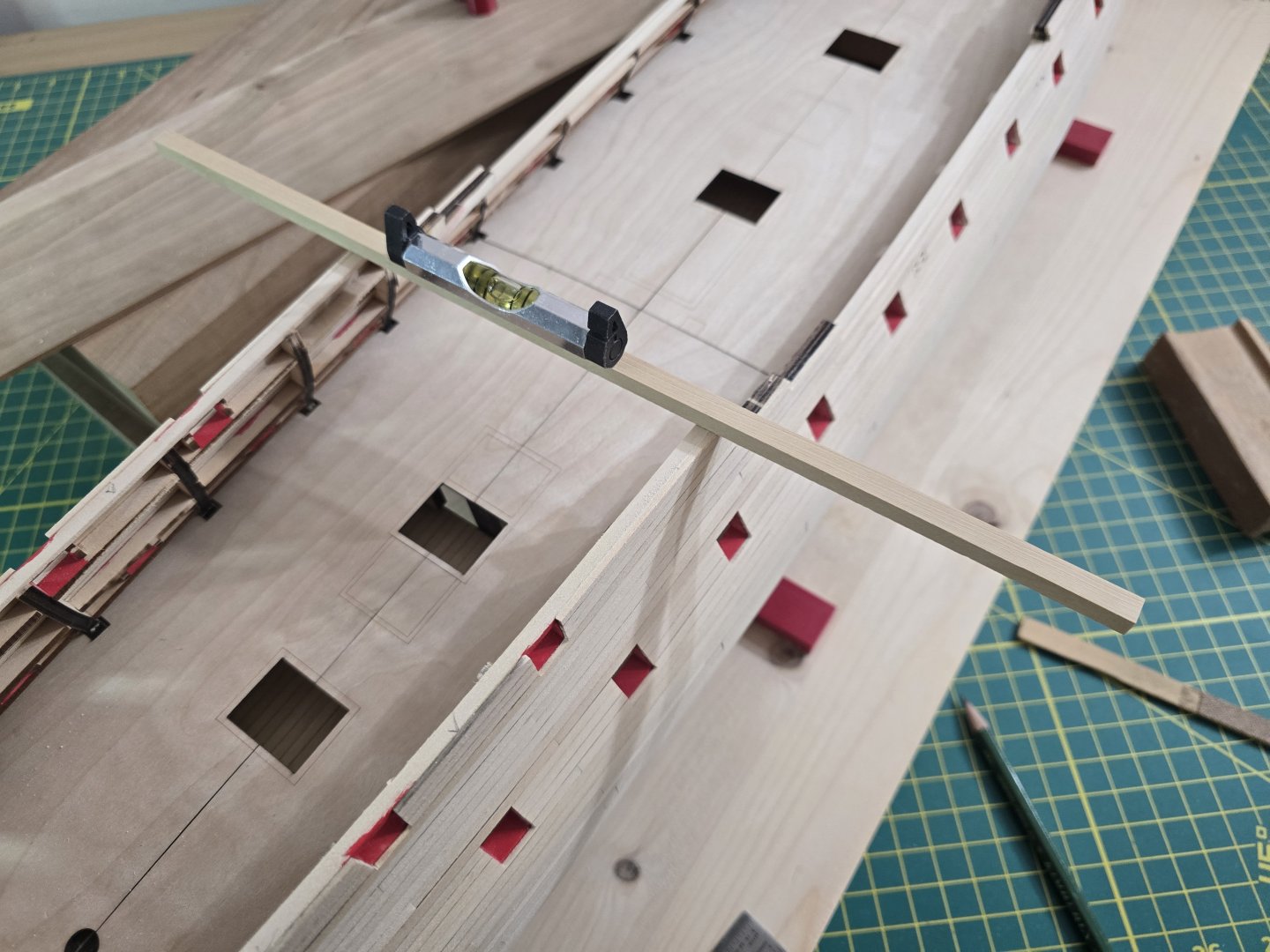
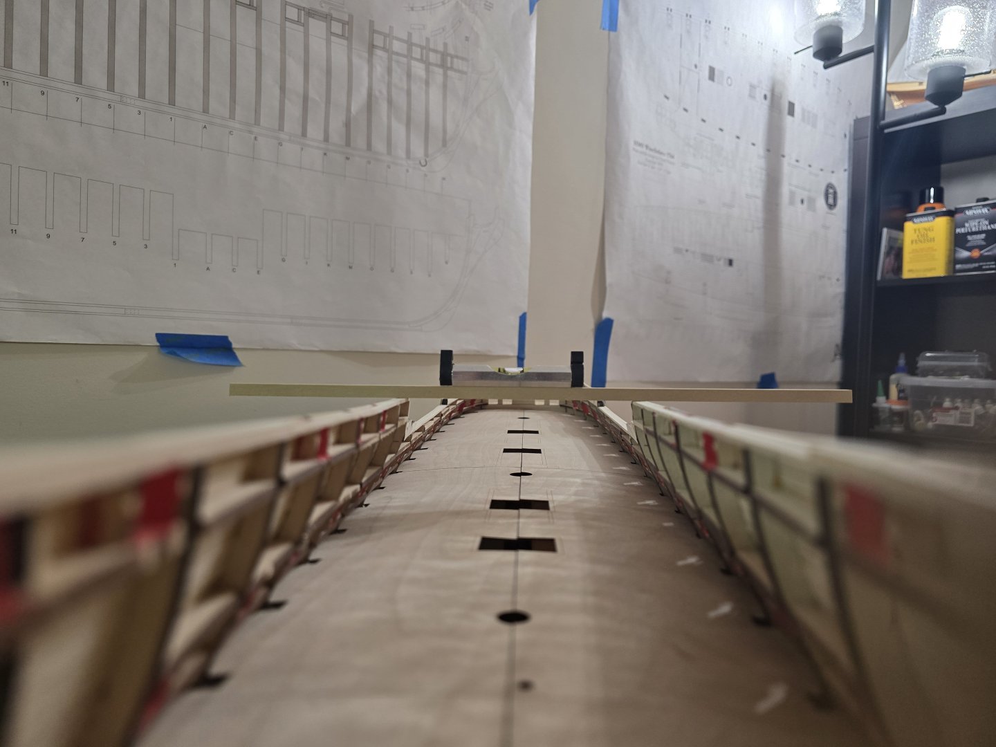
Thanks all! So I finally finished planking the other side of the hull. This step takes so long as each piece must have the correct angle and length. Whew. This feels like an accomplishment! Here are some pictures of the other side finished. What I also did, was to make sure at the stern, the tops of the hull planking were as level as possible for both sides. This should help make the ship look much more even when installing the cap rails a lot later in the build. What I did, was to take a wide strip of boxwood (since it's heavier and harder so it won't bend with a level on top) and place it on different sections of the hull planking and sanded down the tops of the planks where needed to make it as even as possible. After that, I tried my best to sand the hull as smooth as I could with 220 grit sandpaper. This took a little while as there were lots of small spots to try and even out. According to the instructions, the next part was to stain and varnish the entire portion of the hull that was planked! I took about 30 minutes to setup my stations. I first used a pre-stain wood treatment coat. I then wiped off the access after 5 minutes. As it was drying, i mixed together a 1:1 ratio of Minwax Golden Oak stain and clear polyurethane varnish. I needed to thin out the golden oak stain to try and keep from blotching as much as possible. After putting on the stain and varnish, this was the result. In the pic above, there was some blotching near the top above the first few gunports. Please correct me if I'm wrong, but I think quite a bit of that will be painted black a little later in the build. So I'm not too worried. What I was surprised by was how well the pencile edging came through! I made sure to only pencile one edge of the planks. I am glad I didn't darken both plank edges that meet or it would be too dark! Please let me know what you guys think! It will look different once it's painted and the wales/ molding strips are added. But I do feel I finished a huge step in the build and it feels very good! 😀 Thanks all for reading and for your comments and likes. I do appreciate them a lot! Jeff


-
Hey all! Thank you for all your comments and likes! I have finally finished planking the gun deck outer hull. It really does take a long time to plank the hull on the gun deck. Here is an example of a complex strip I have to create to plank around the gunports. This piece was created for the top of the gun ports but also has to go around a sheave shell. These pieces take a while to make! The next pictures show how far I have gotten so far with the planking. The planking will go faster until I reach the quarterdeck gunports. At least the quarterdeck gunports do not require the rabbet as the gun decks gun ports do! Whew! I'm almost there! Thanks all! Jeff


-
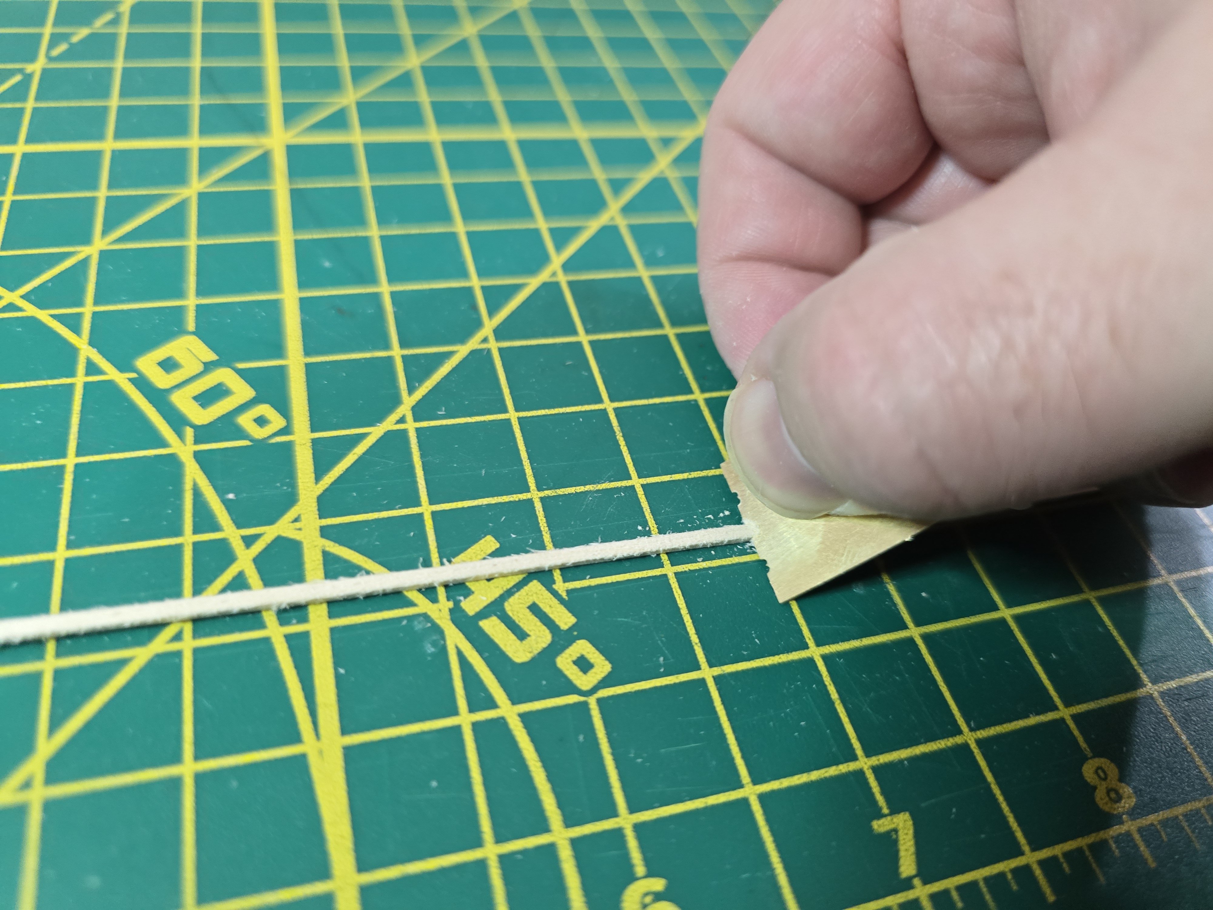
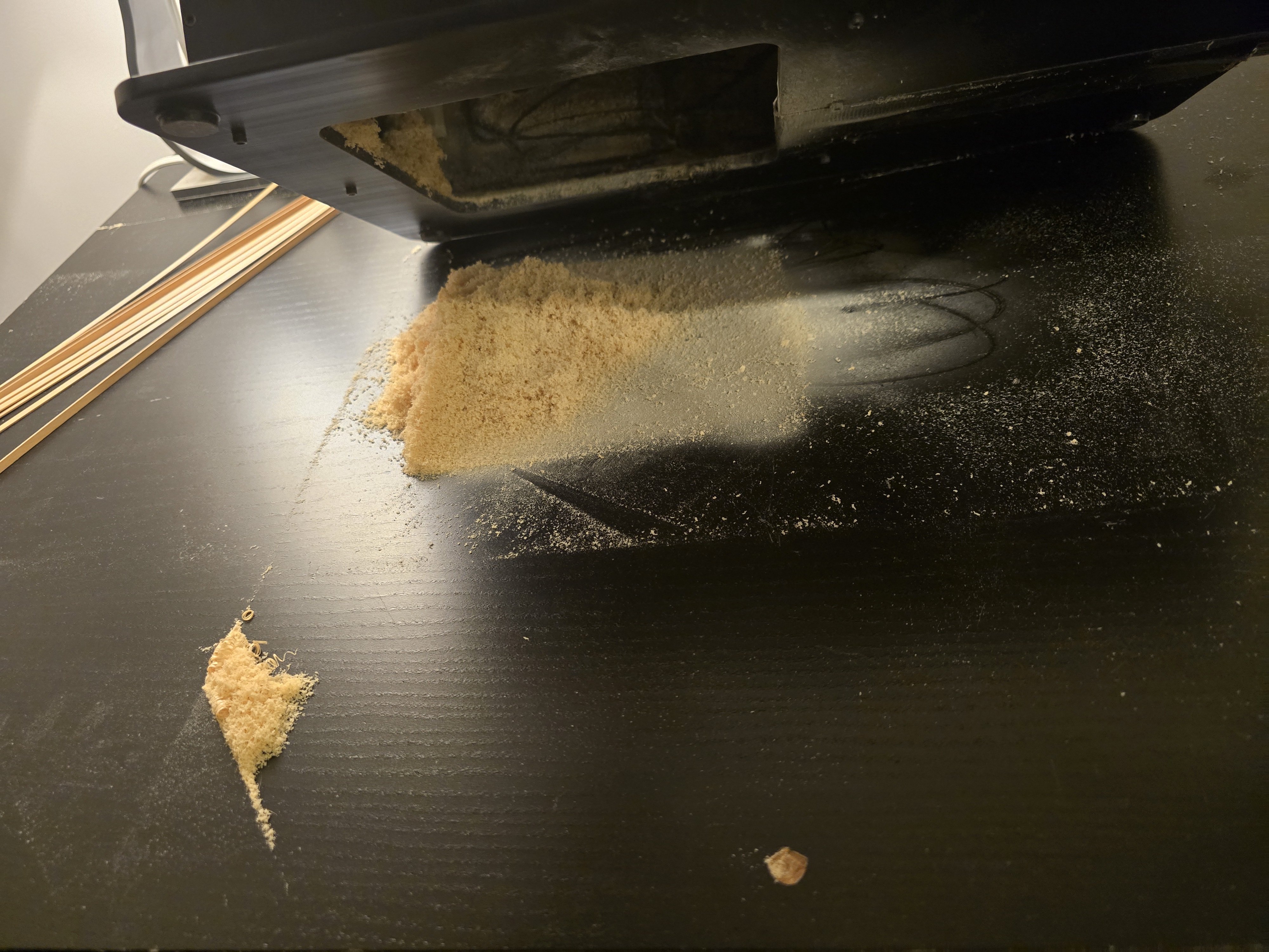
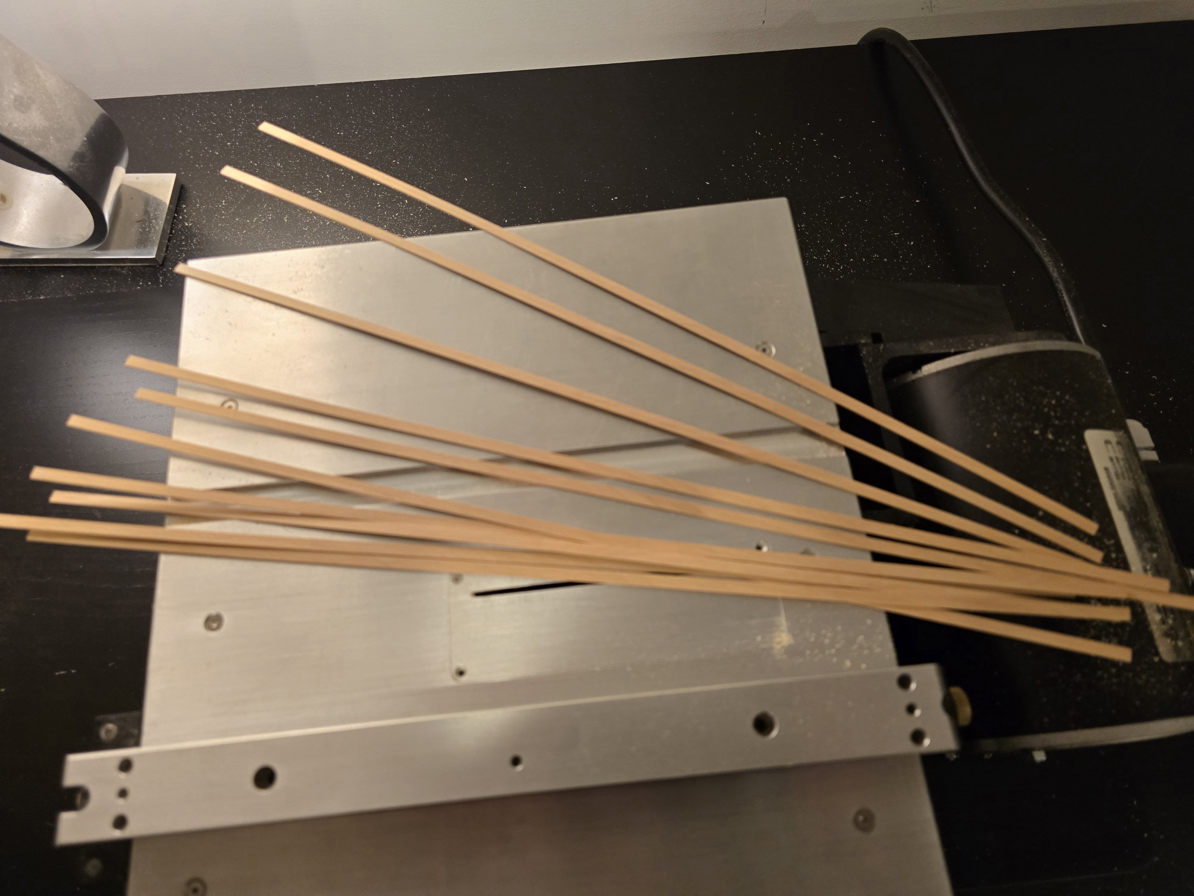
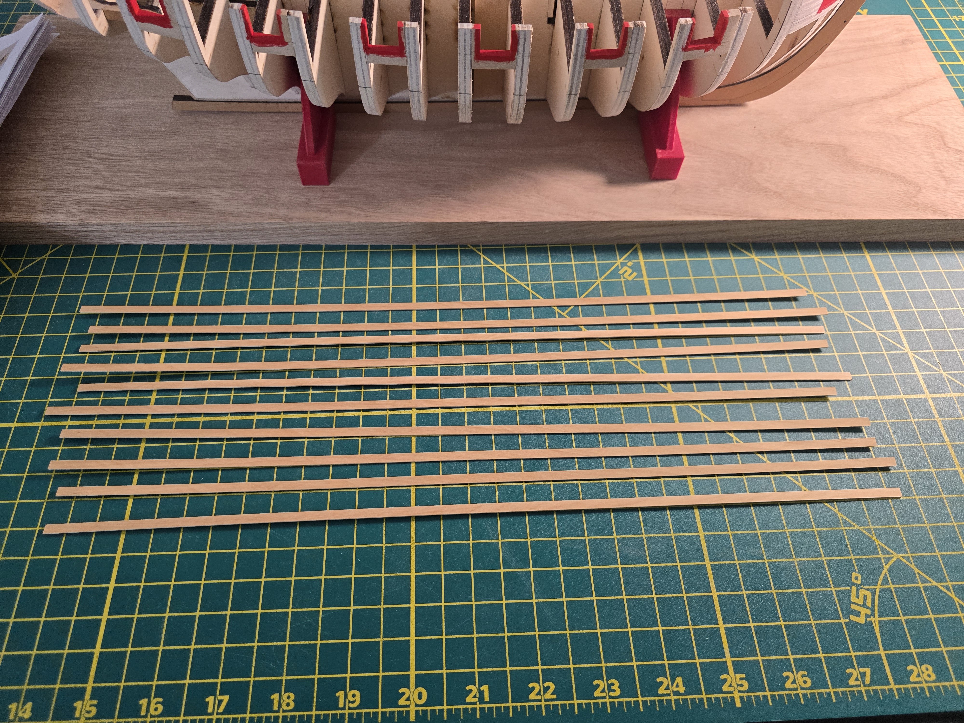
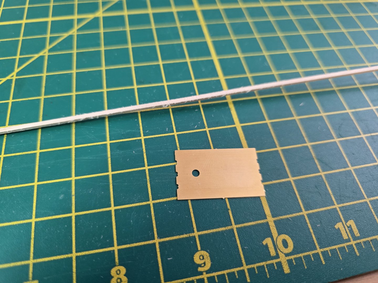
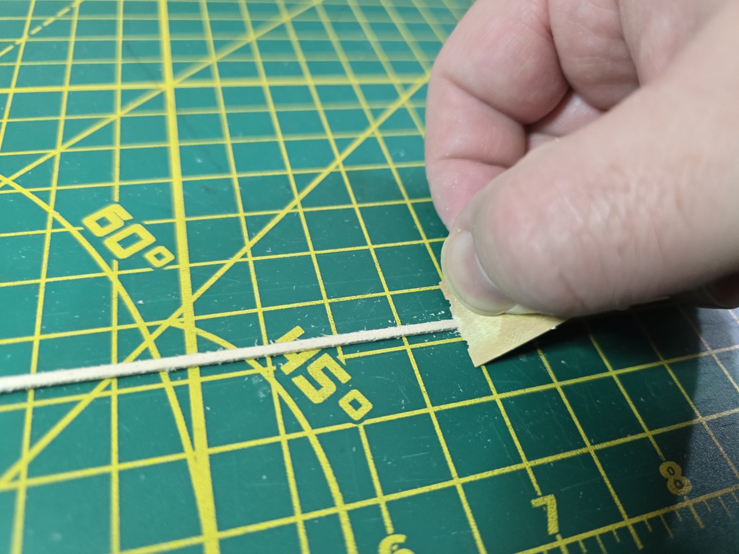
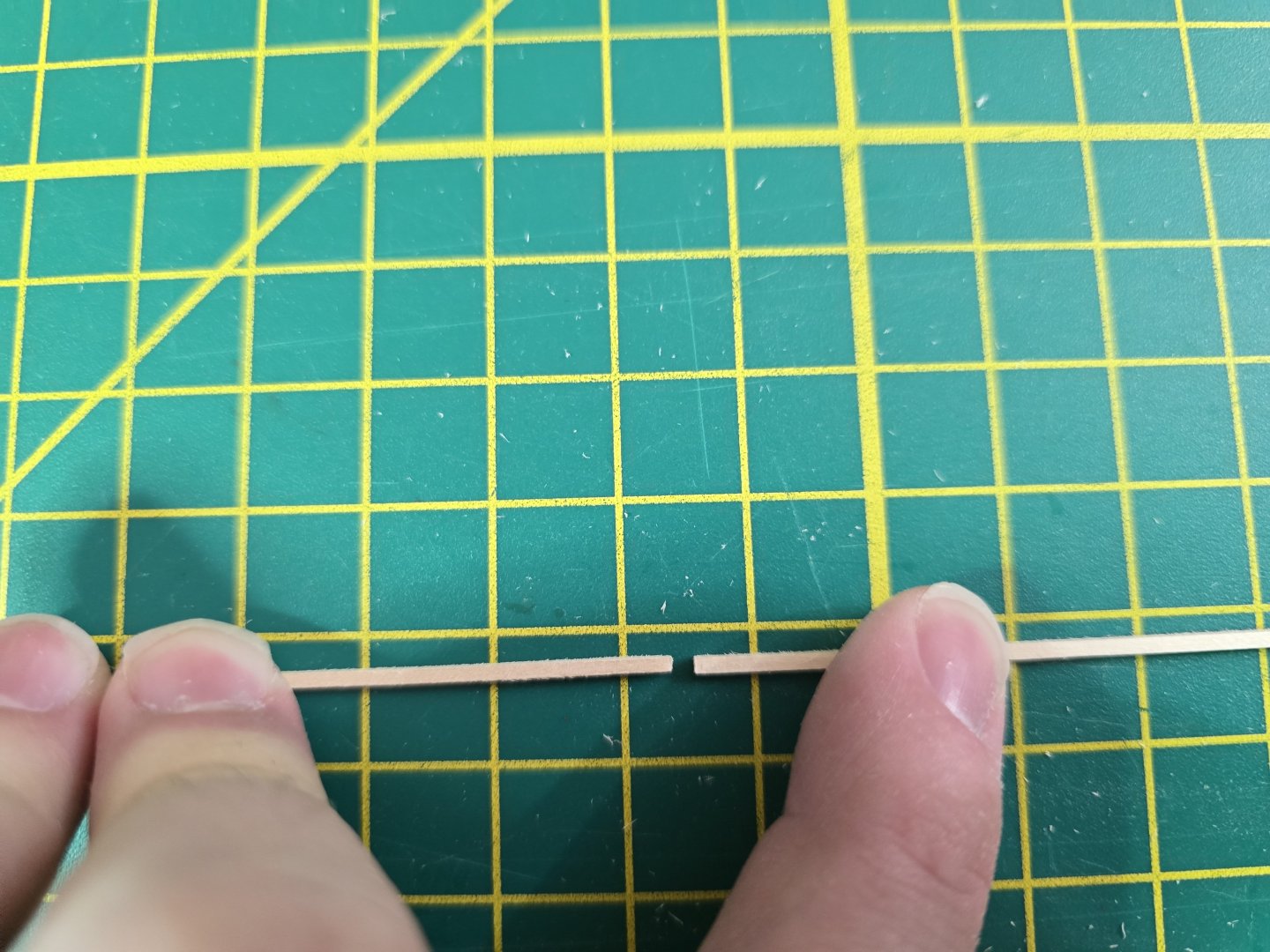
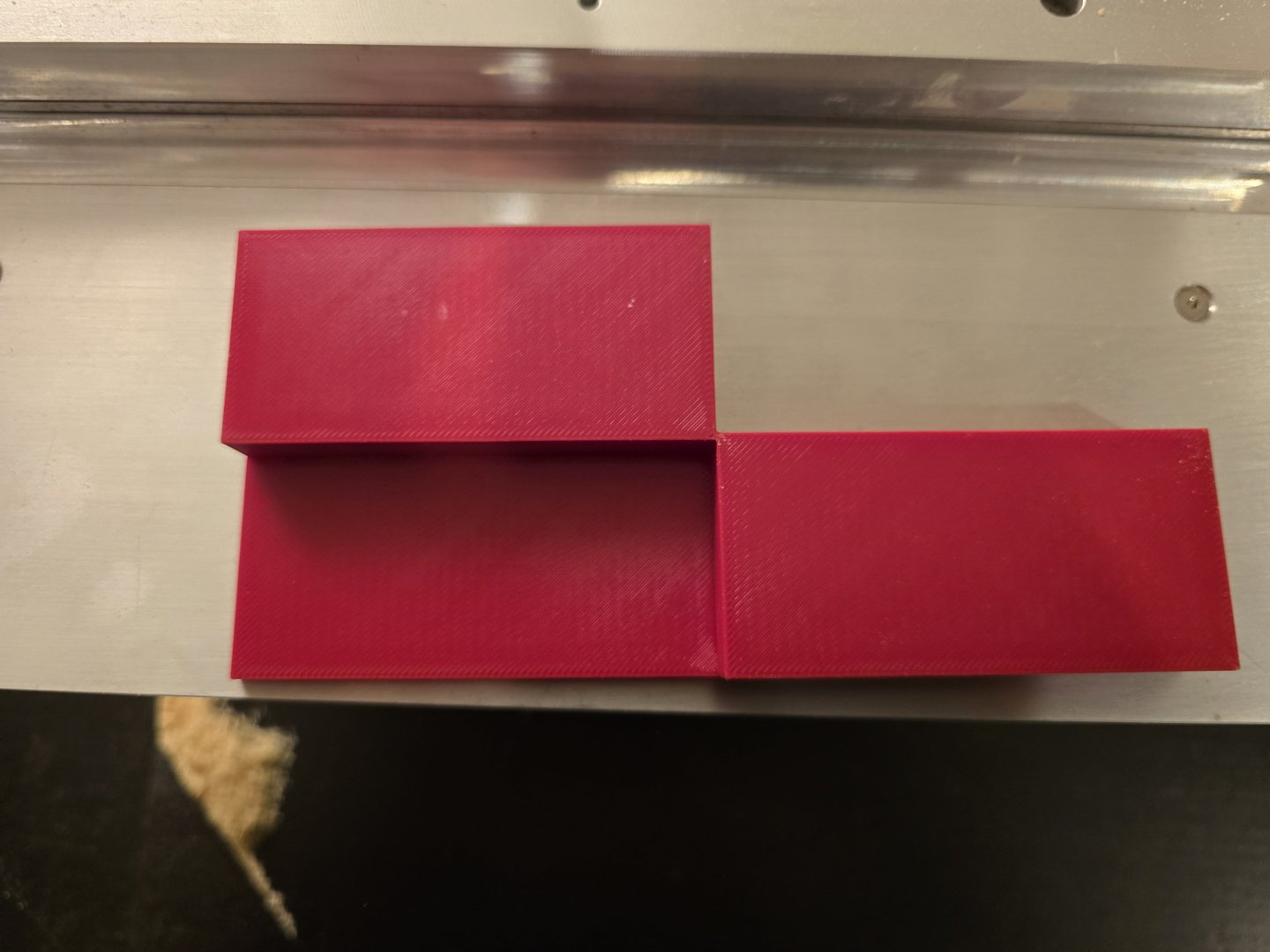
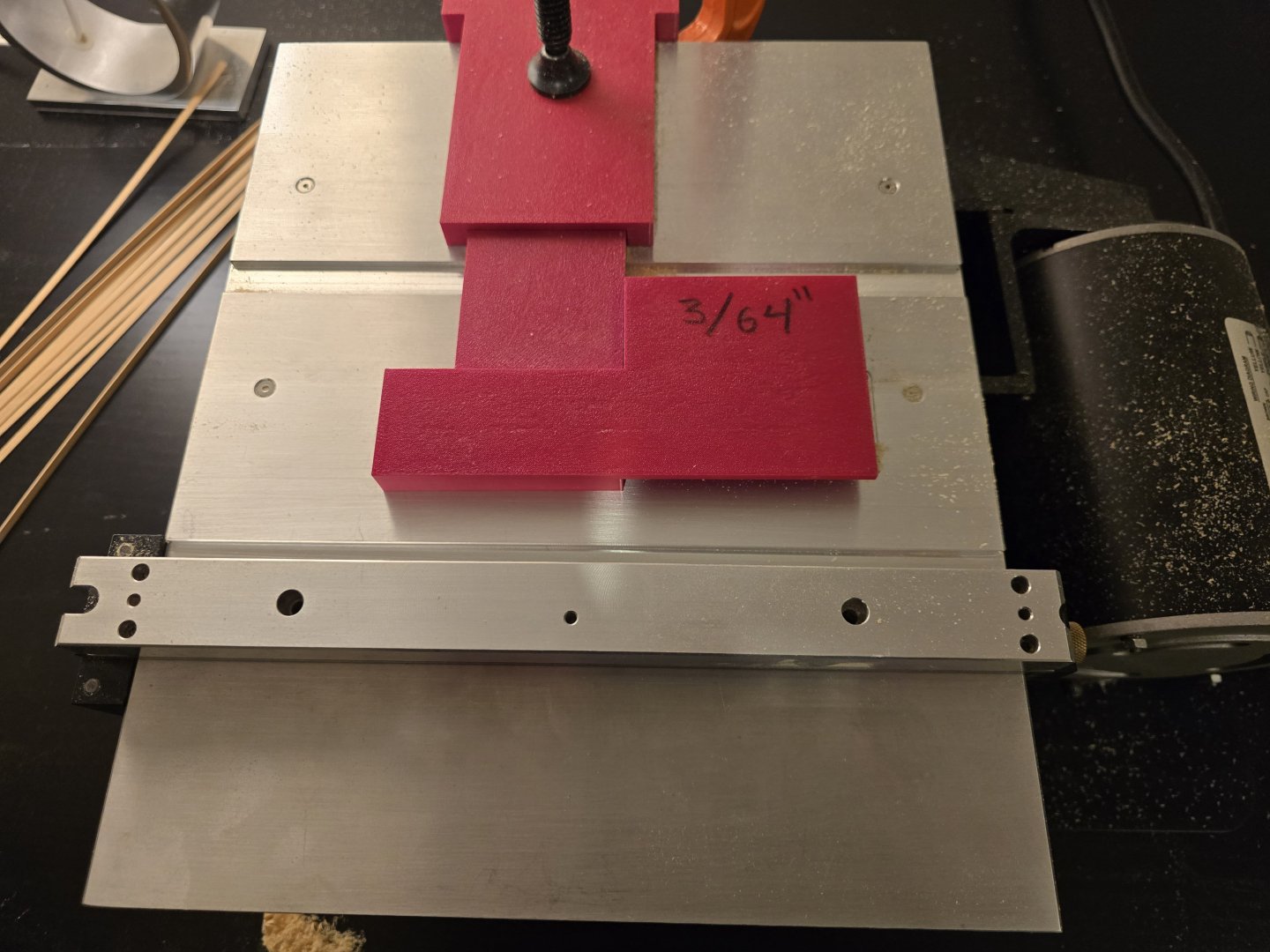
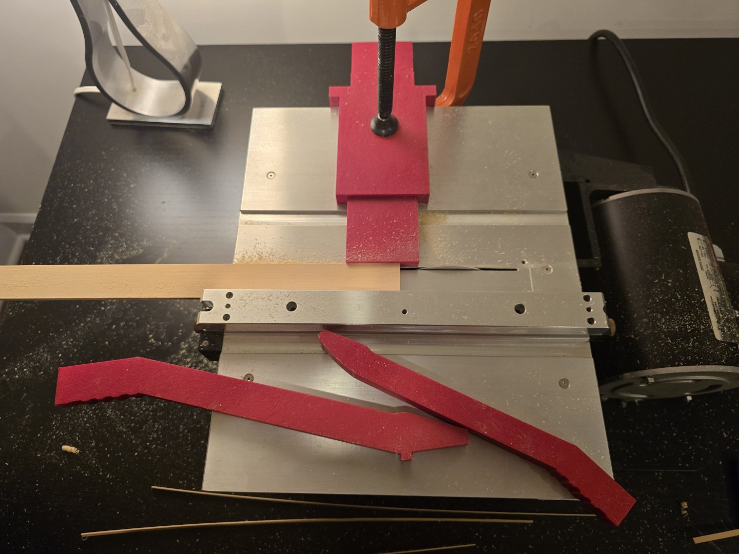
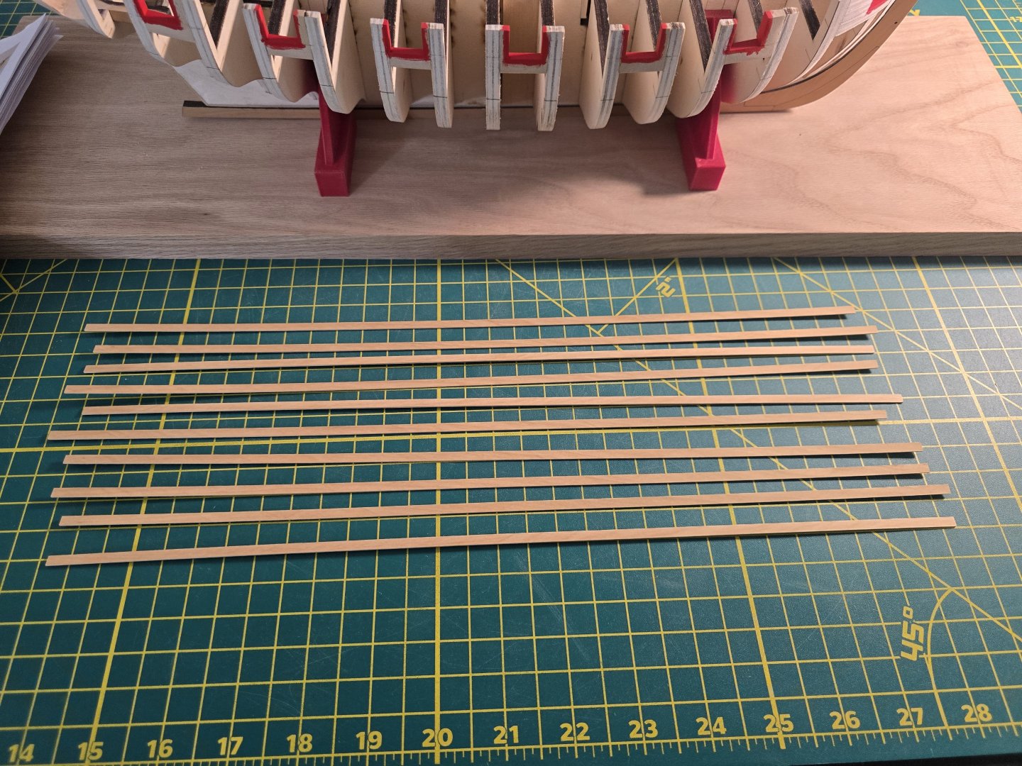
It's time to mill! I won't always make a post about milling strips (this will probably be the only one) but I thought it would be important to show this as it's vital to the building process for Cheerful. Firstly, this is how I milled the 5/32" strips for the wales. There are 2 rows of planks for the wales (first layer) and each row takes 2 strips. So this means I need to mill 8 strips to complete the first layer of the wales. I always make a few more strips just in case. So I will be milling 10 strips total. The tools that I use for milling strips are: 1) My Brynes table saw ( wonderful table saw) 2) A push rod 3) Another rod (curved at the end) to hold in my other hand to help keep the wood running smoothly through the saw blade 4) The saw blade (3" 90 tooth .03 kerf slitting blade) 5) A 3/64" spacer 6) A jig to make sure each strip will be 3/64" wide 7) Super important!! Goggles for my eyes 8) 5/32" wood sheet For me to get the correct width (3/32") I 3D printed a spacer. I then place the spacer on the saw blade so I could then run my 3d printed jig up next to it for the correct width. This is the underside of the spacer. I placed the saw blade up against the under edge of the spacer (the left side middle edge). I hope that makes sense. The blade actually goes UNDER the spacer as you will see below. The 3/32" width comes from the distance between the wall of the spacer that butts up against the blade, and the other side's OUTER edge ( in the pic above, that outer edge is the right most top edge). I know that's a lot of words. But I hope the pic below helps to clear it up. Then I place my 2 piece jig up against the spacer. The jig is in 2 parts. The bottom part of the jig can move freely back and forth so it can but up against different spacer widths. I then clamp it in place. This really helps getting even, consistent cuts from the wood sheet. I then make a test cut to validate the correct width. The left stick is the push stick I 3D printed, the right stick is curved at the end so it doesn't cause as much friction when making sure the wood is held properly while being pushed through the saw. I also sanded it as well with 220 then 300 grit sand paper to try and get it smoother. The only reason all my 3D printed jig and things are red, is because that was the only filliment color I had at the time! I used Blender ( which is free) to create the models. For filliment, I printed with PETG + as its a little more durable than normal PETG. I have a good reason why I place the wood sheet against the fence and move the fence each strip. Kickback. I tried to place the wood edge being cut on the fence so I wouldnt have to move the fence each time. But this cause a lot of kick back (shooting the strip backwards like a bullet) and it was also hard to keep the correct width at the end of the strip since very little to no wood was then touching the fence. I learned very quickly to never position myself in front of the saw blade in case there is kick back. Won't be a good time for my stomach! It's so strong that sometimes the kick backed strip can tear through dry wall insulation! Secondly, when I position the sheet and move the fence up to meet it, I don't push the fence hard against the wood sheet. Instead, I put the sheet of wood against the jig, then bring the fence up so it just touches the wood sheet. I then tighten the left side of the fence (looking at the picture above) I then SLIGHTLY move the back part of the fence away from the saw blade (very small.. trying for less than 1mm) this allows a little wiggle room for the sheet to not get stuck on the fence as the wood sheet gets pushed though the blade. This prevents kickback from the sheet. I have never had the sheet kickback with this technique. Lastly, I ALWAYS wear safety goggles and stand facing the side of the saw. This way, there's no way I will be in the line of fire in case there is some kickback. When I'm pushing the wood through the saw blade, I go slow as to not cause too much heat buildup on the blade and wood. Pushing the wood too fast can cause the wood to burn and burn residue can pile up on the blade. This is especially true for slitting blades as they are very thin and tend to get hot quite a bit quicker than other blades. Burnt looking blades can leave residue on subsequent strip cuts, making new cuts loom burnt. No good. Here are my 10 strips all cut. It looks a little fuzzy. So here's another pic. Lastly, just these 10 strips make all this sawdust. Quite a bit more than one would think. I need to 3D printed an adapter to connect my vacuume to the vacuumed port on the side of the saw. I know this was a little long winded. But I just wanted to share how I cut strips. The learning process for me took a long time and with many failed attempts at milling strips correctly and consistently. It felt more of a secret art than anything! If any of you have good tips for milling wood, please feel free to share! I hope to start planking the first layer of wales tomorrow! Though, I do need to order some more sheets for all the planking that needs to occur. Thanks all! Jeff


-
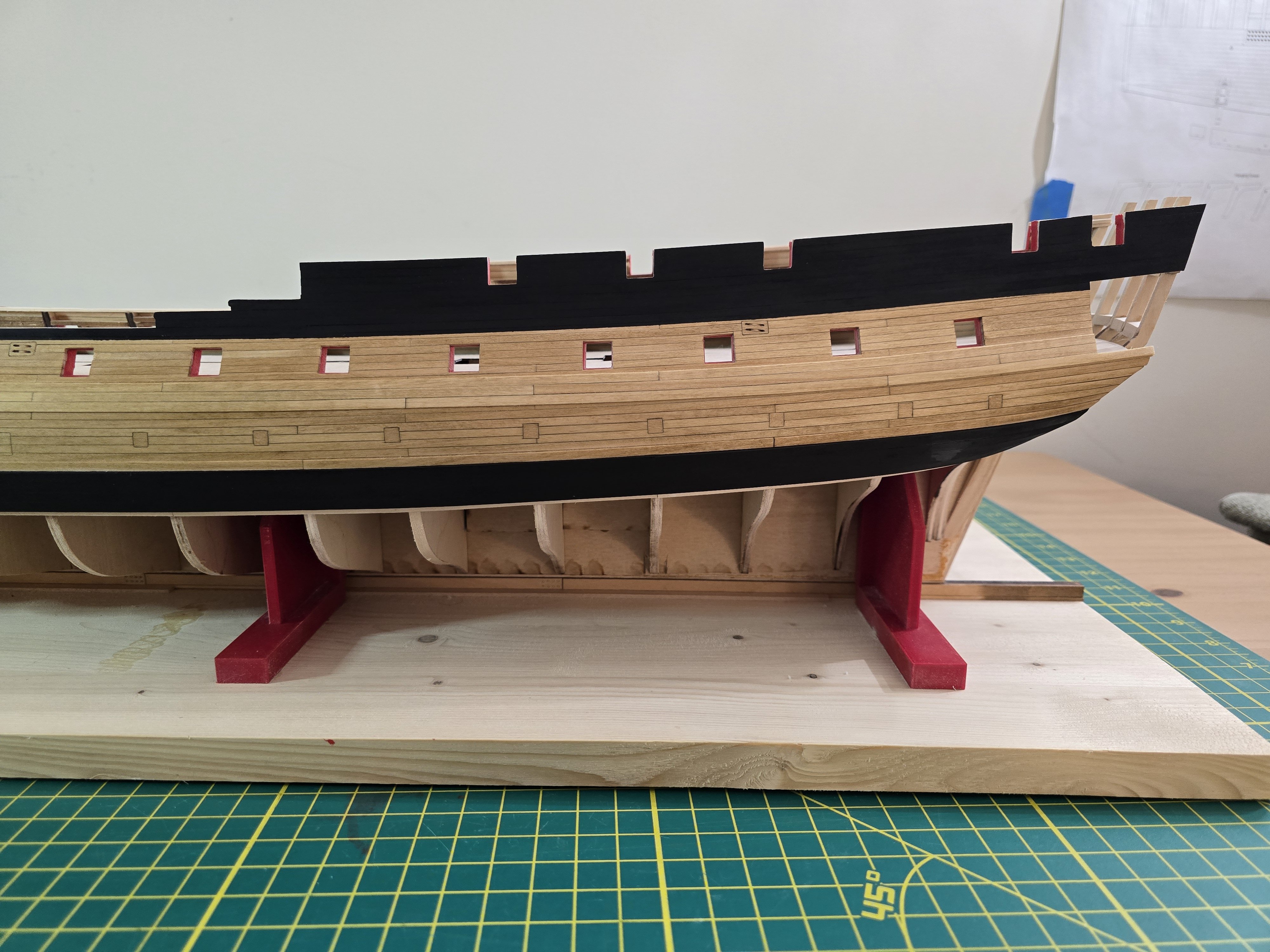
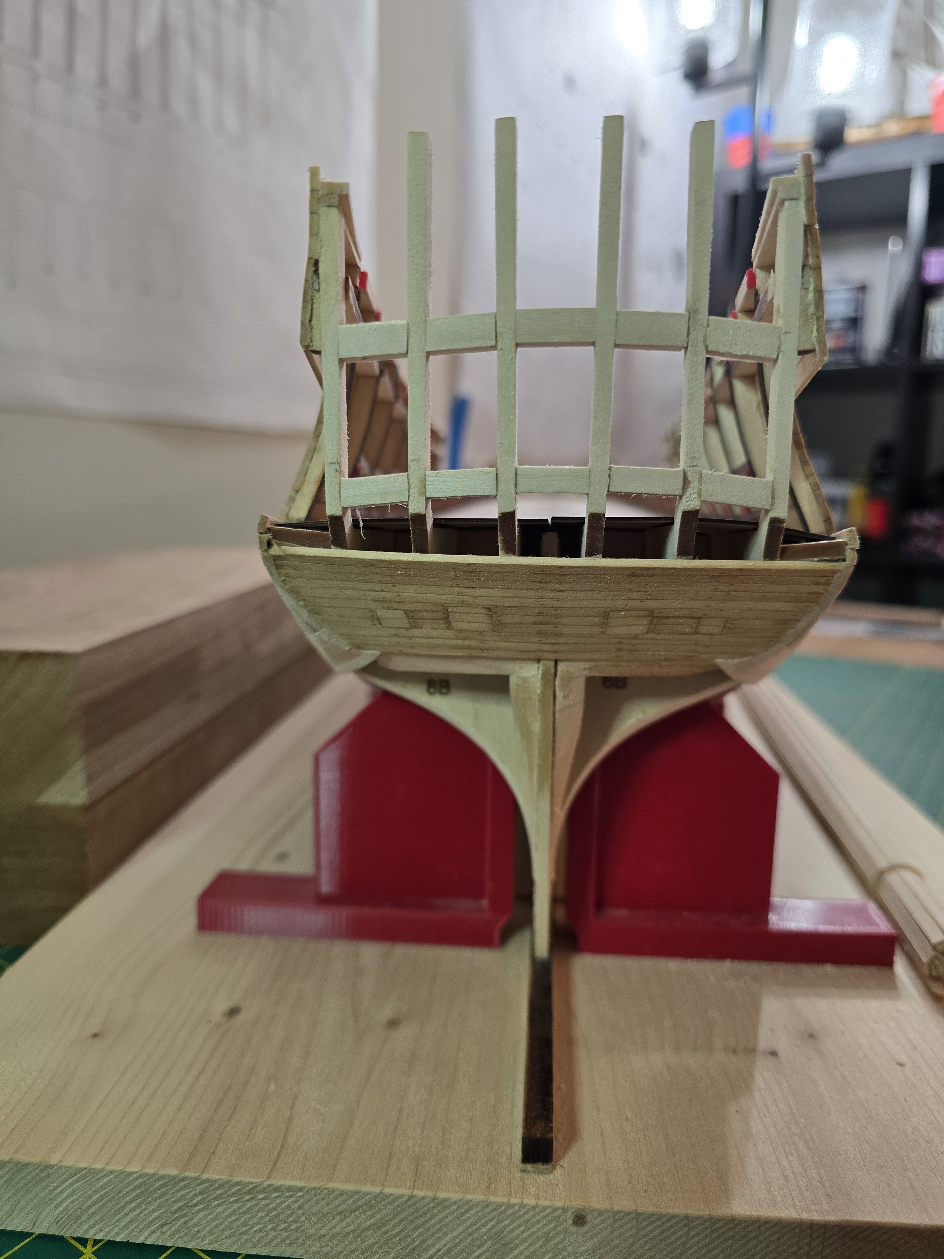
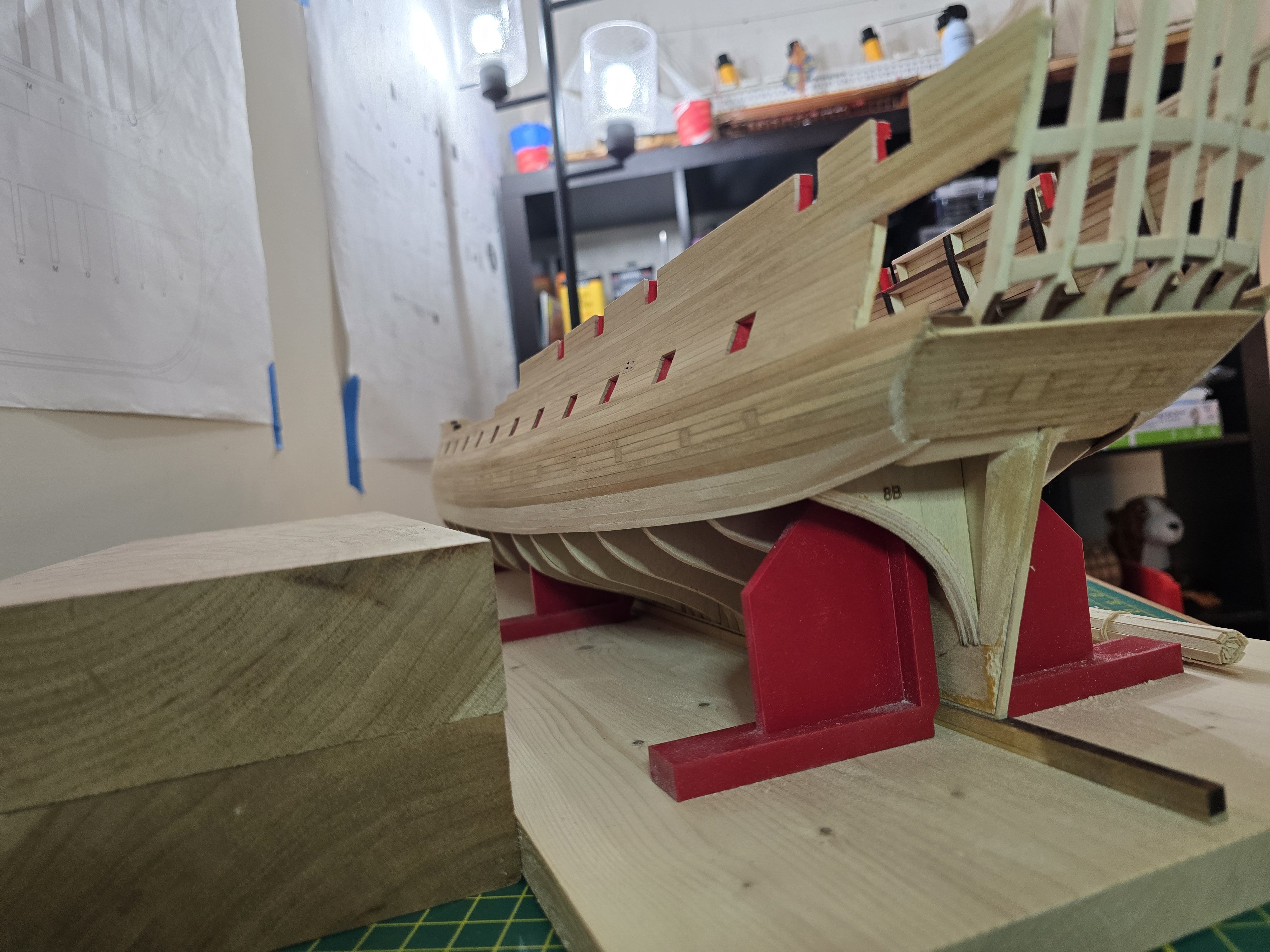
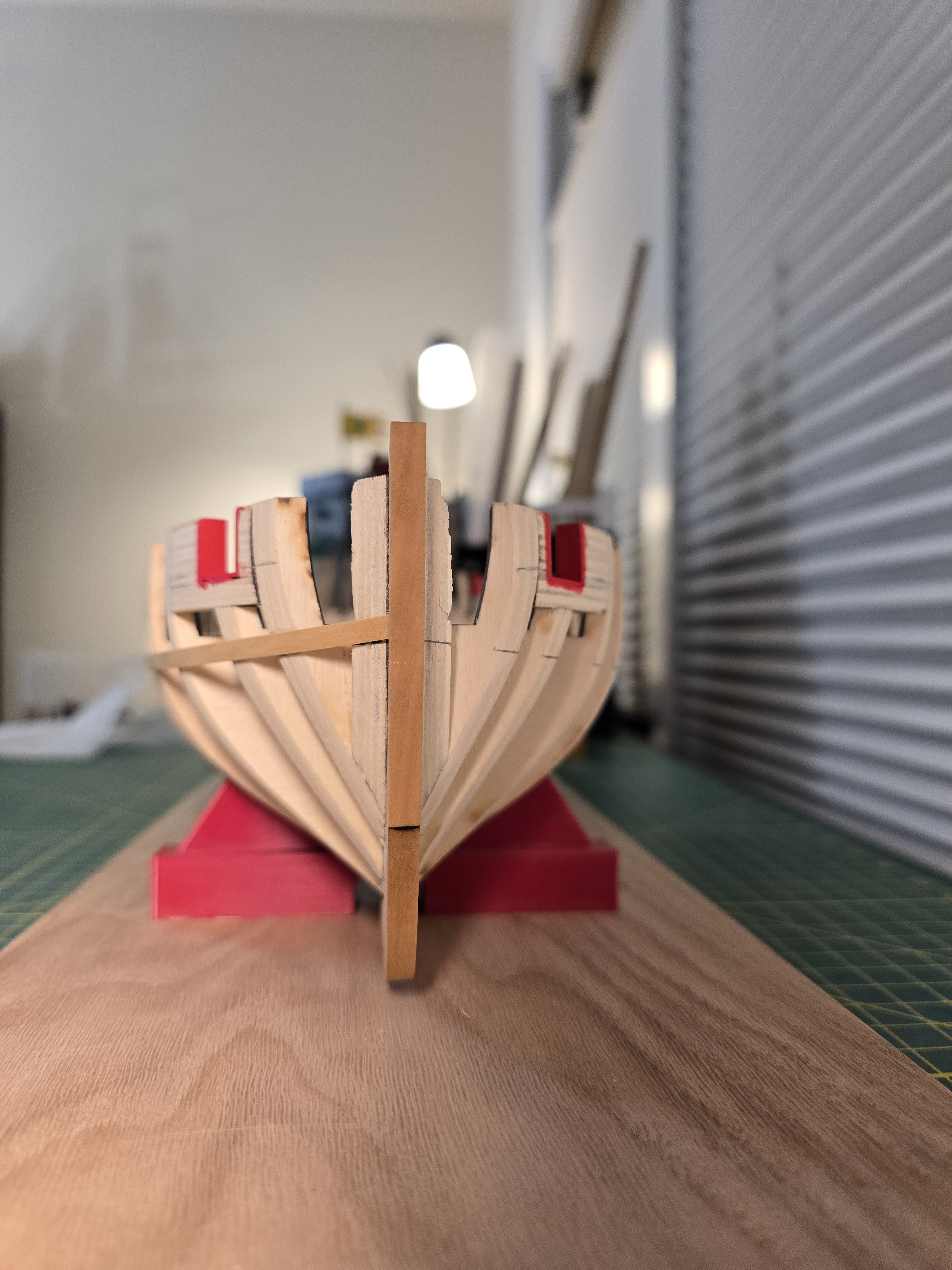
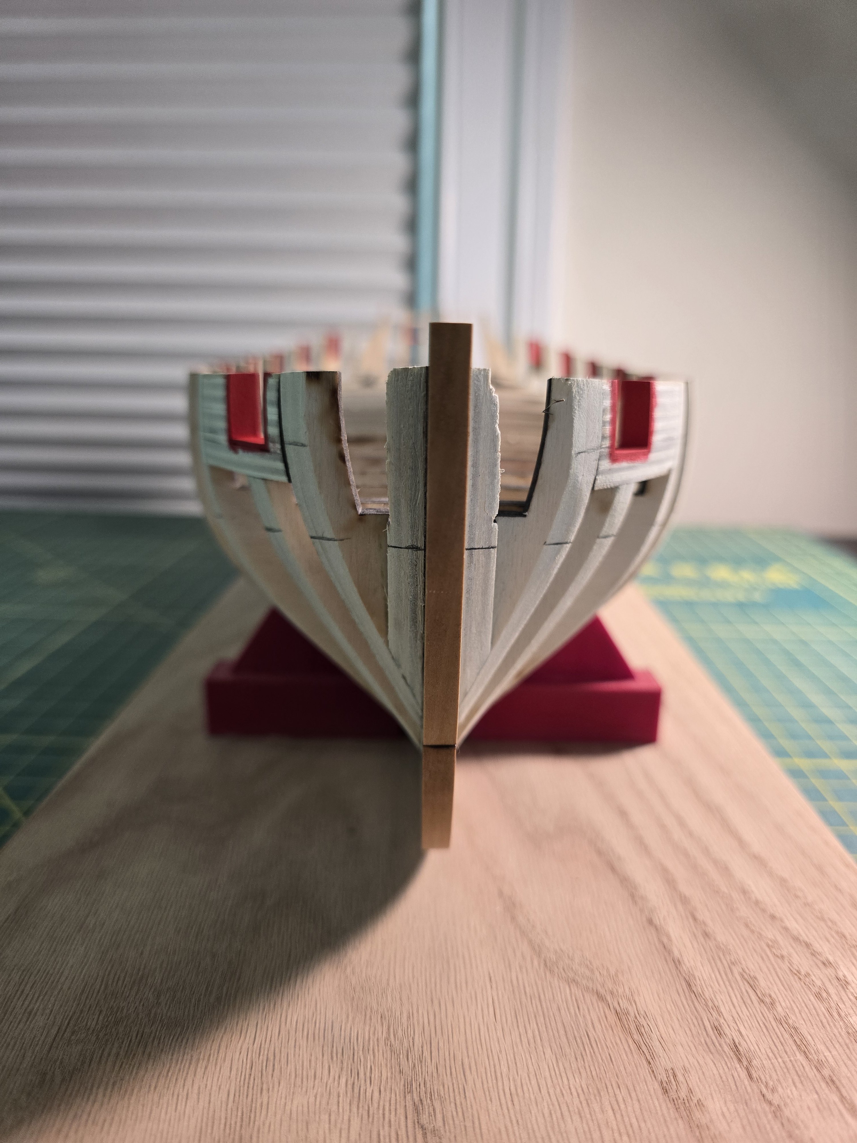
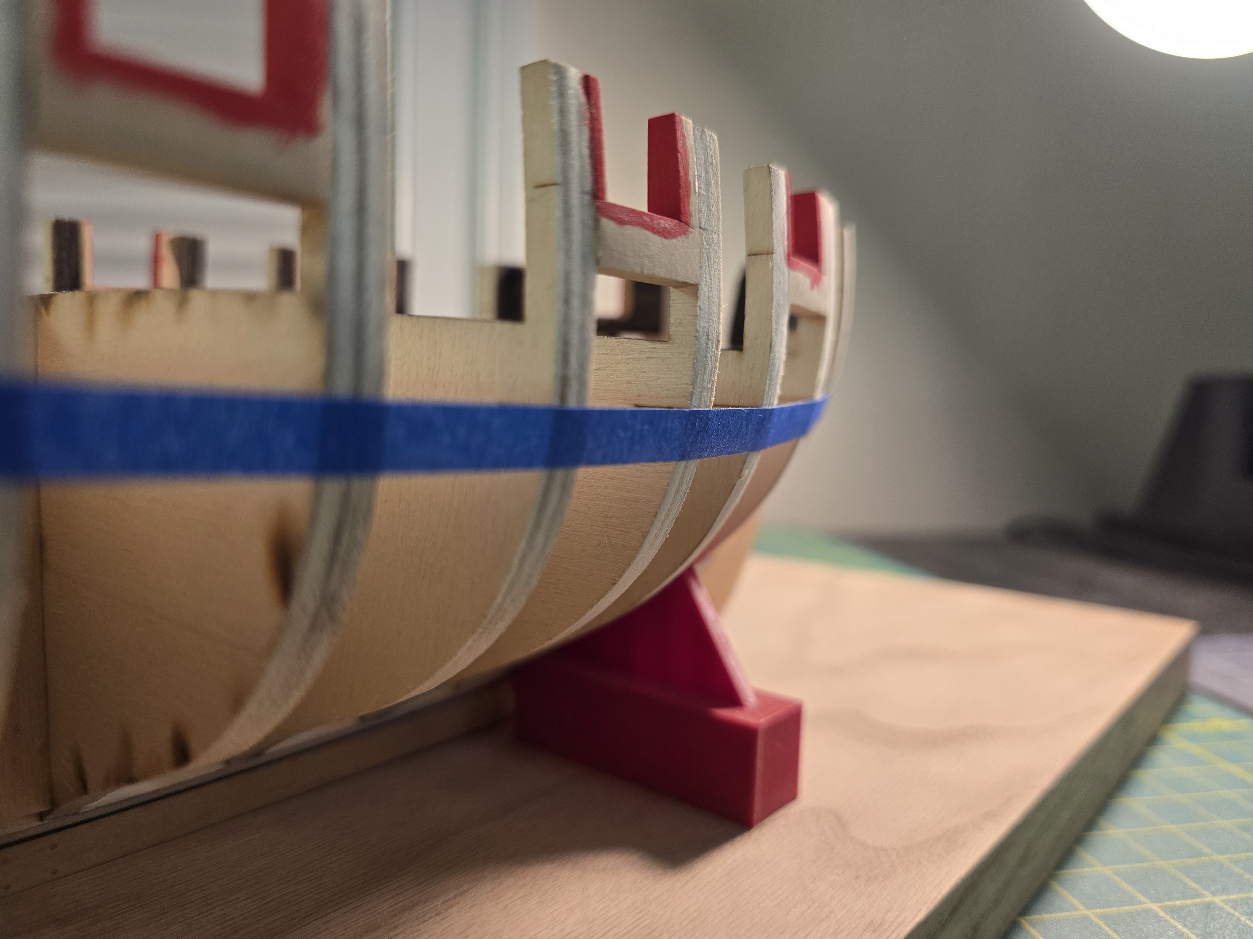
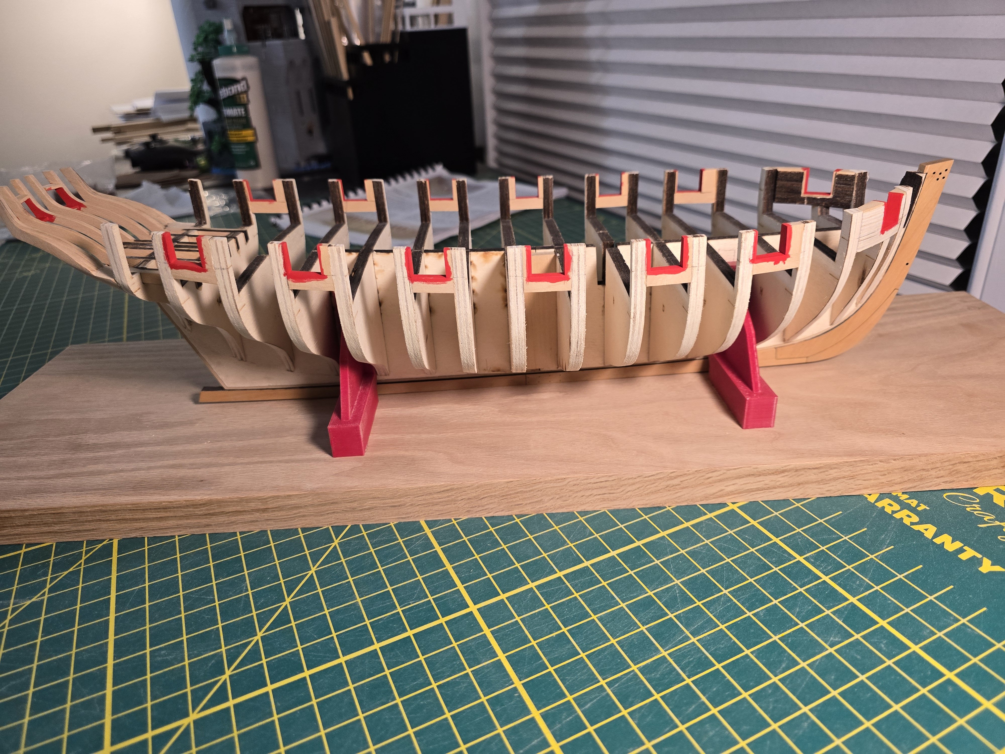
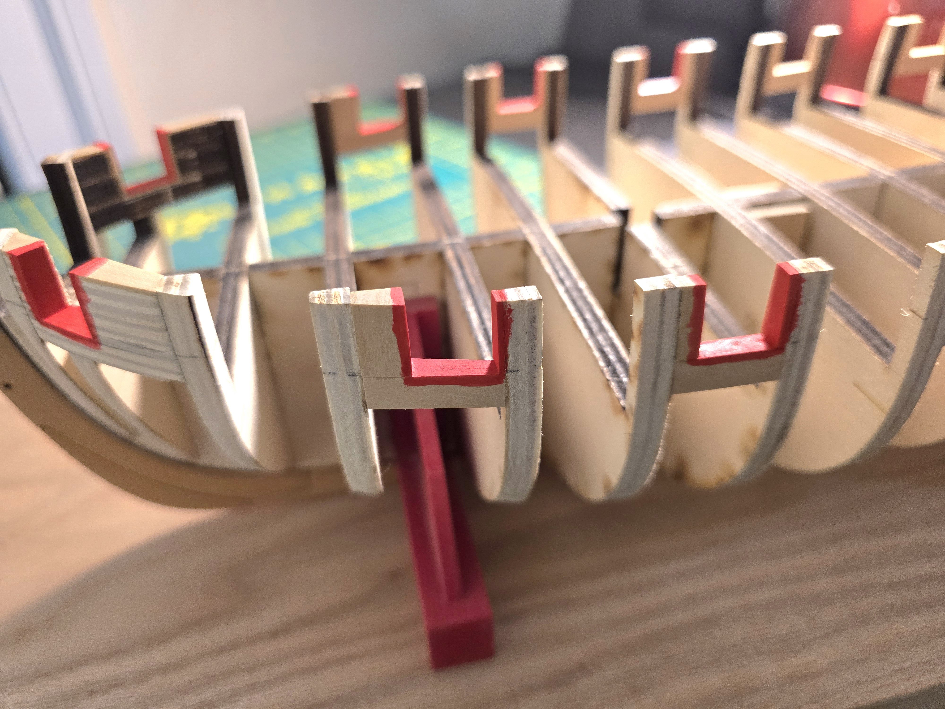
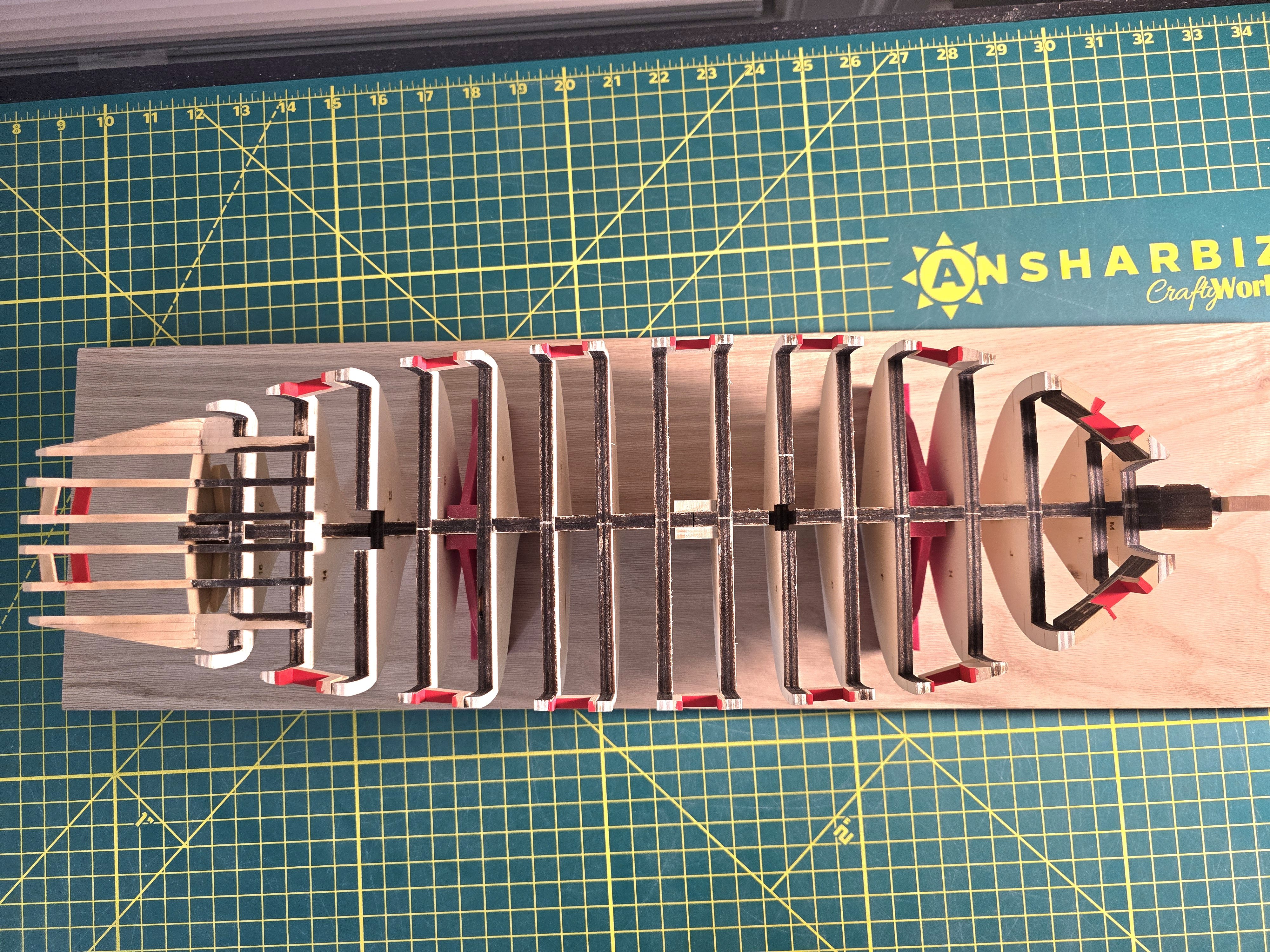
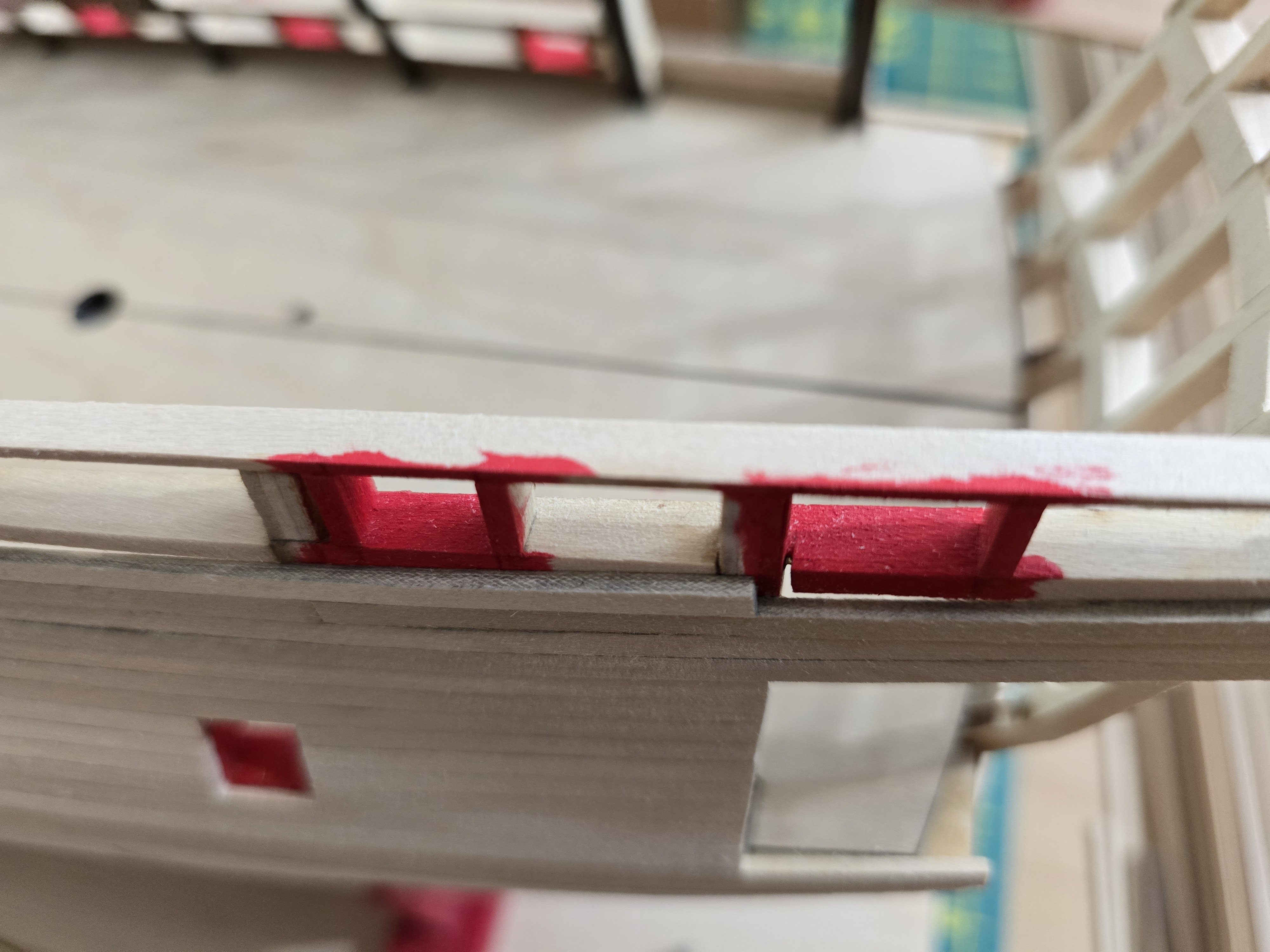
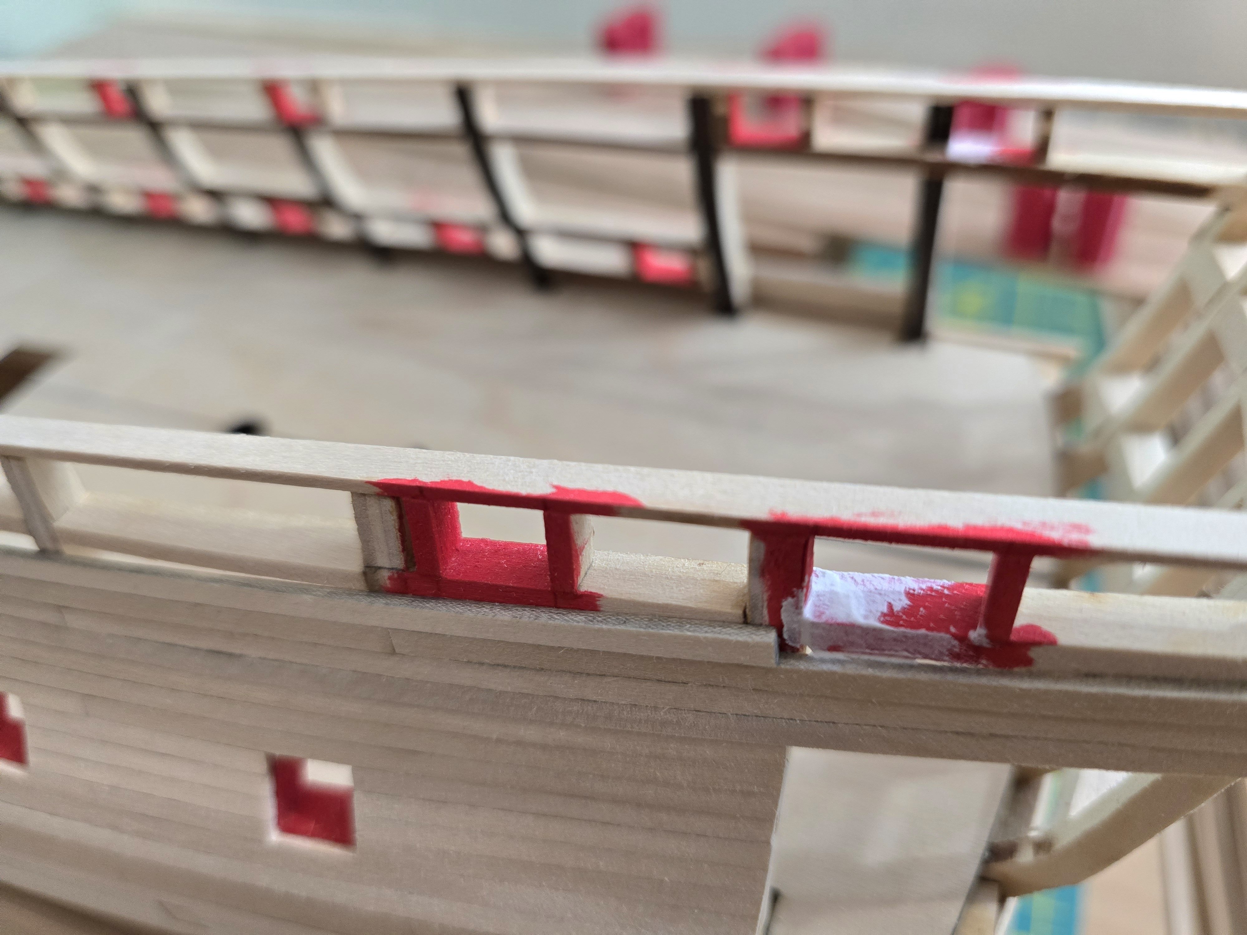
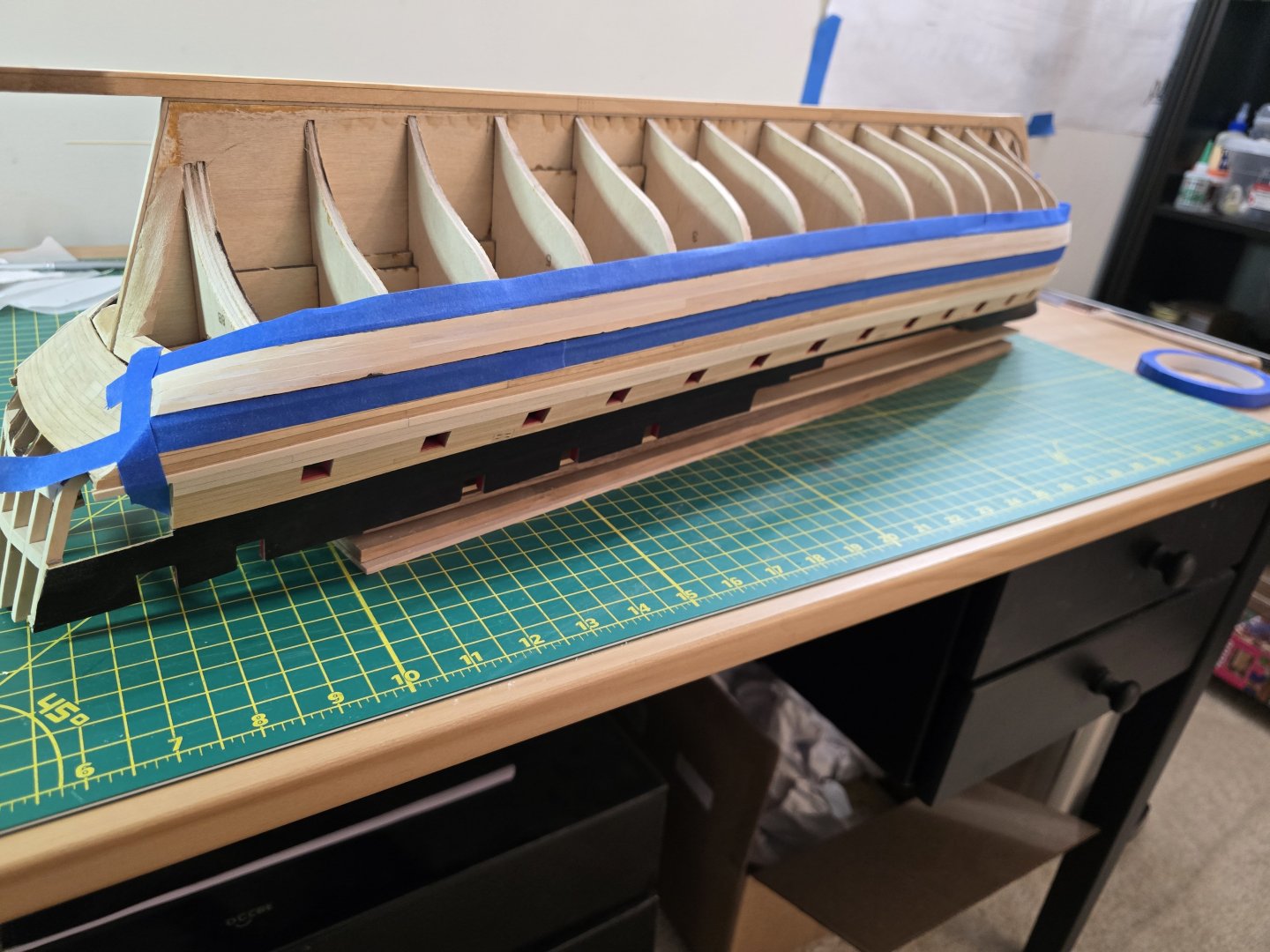
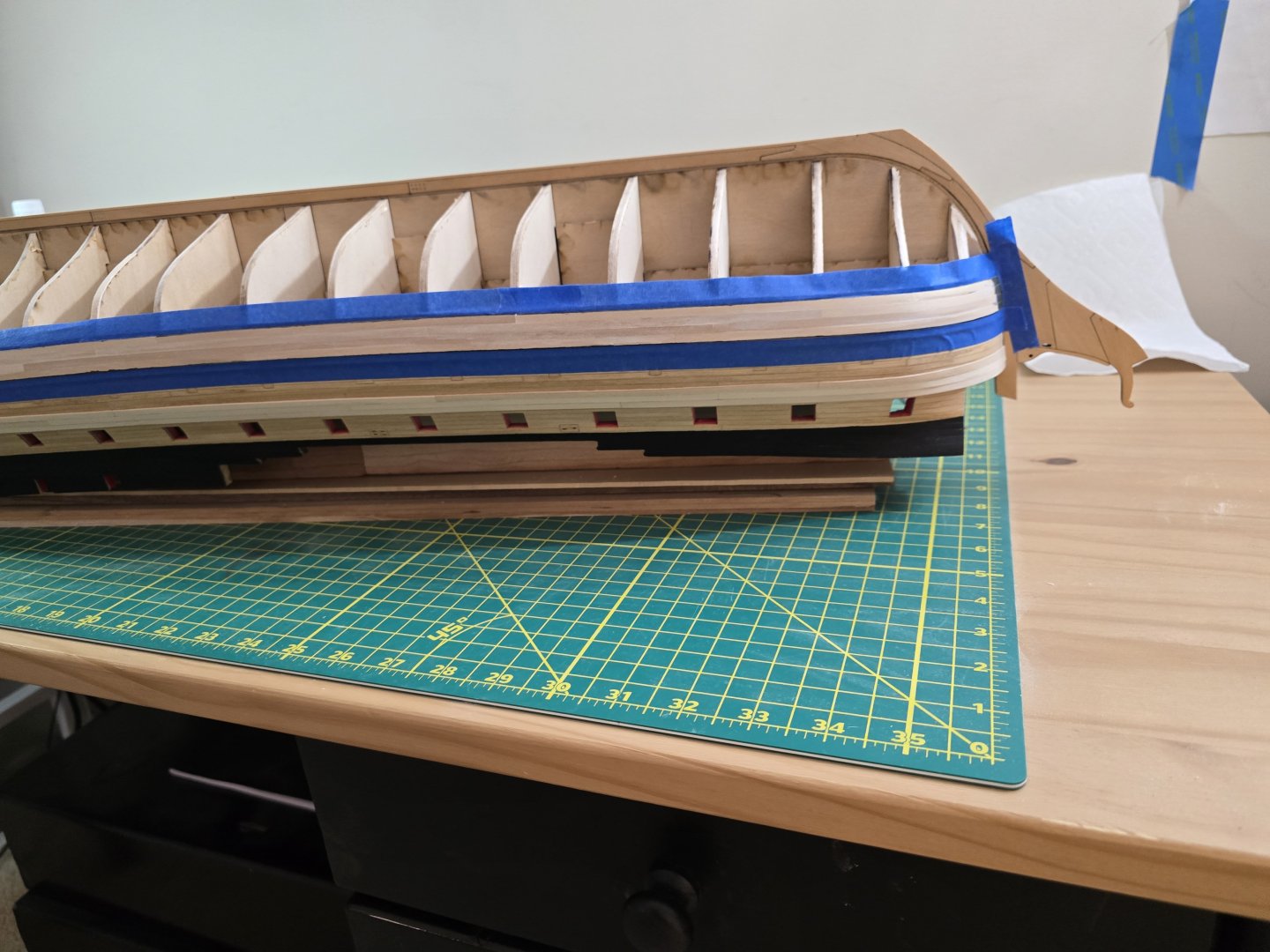
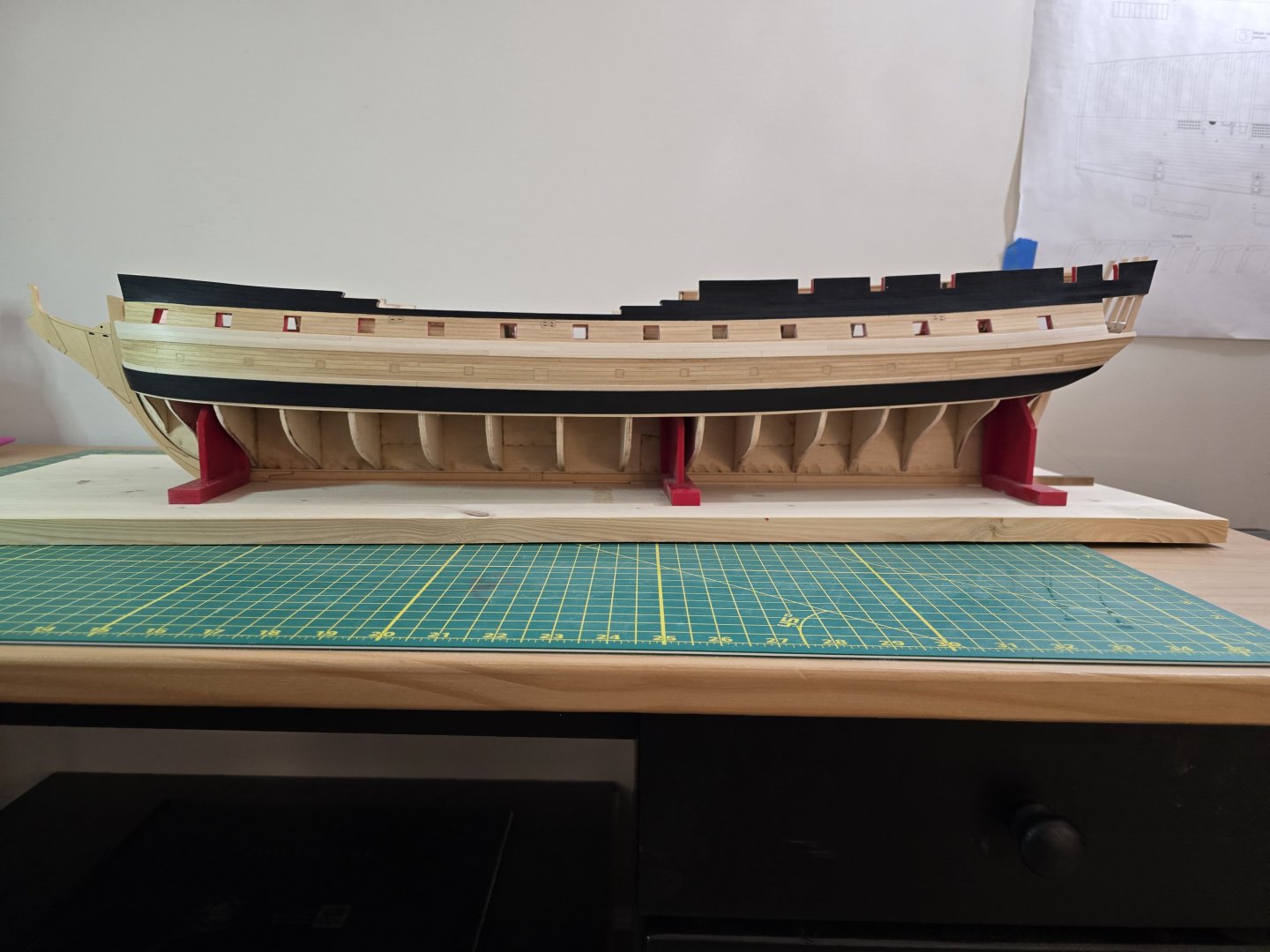
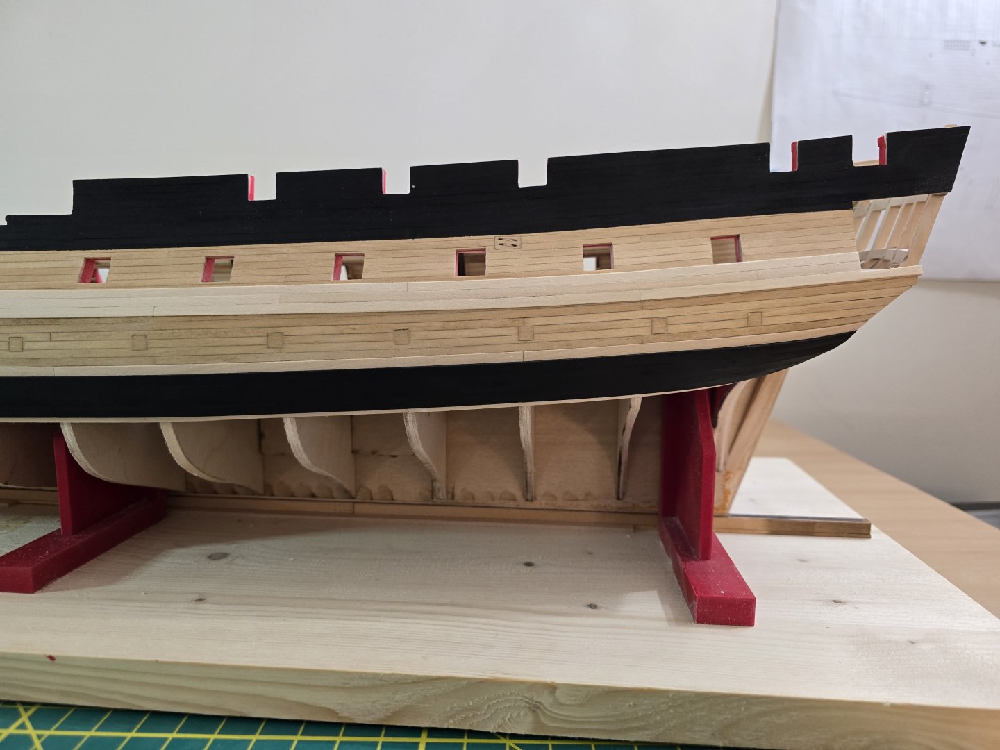
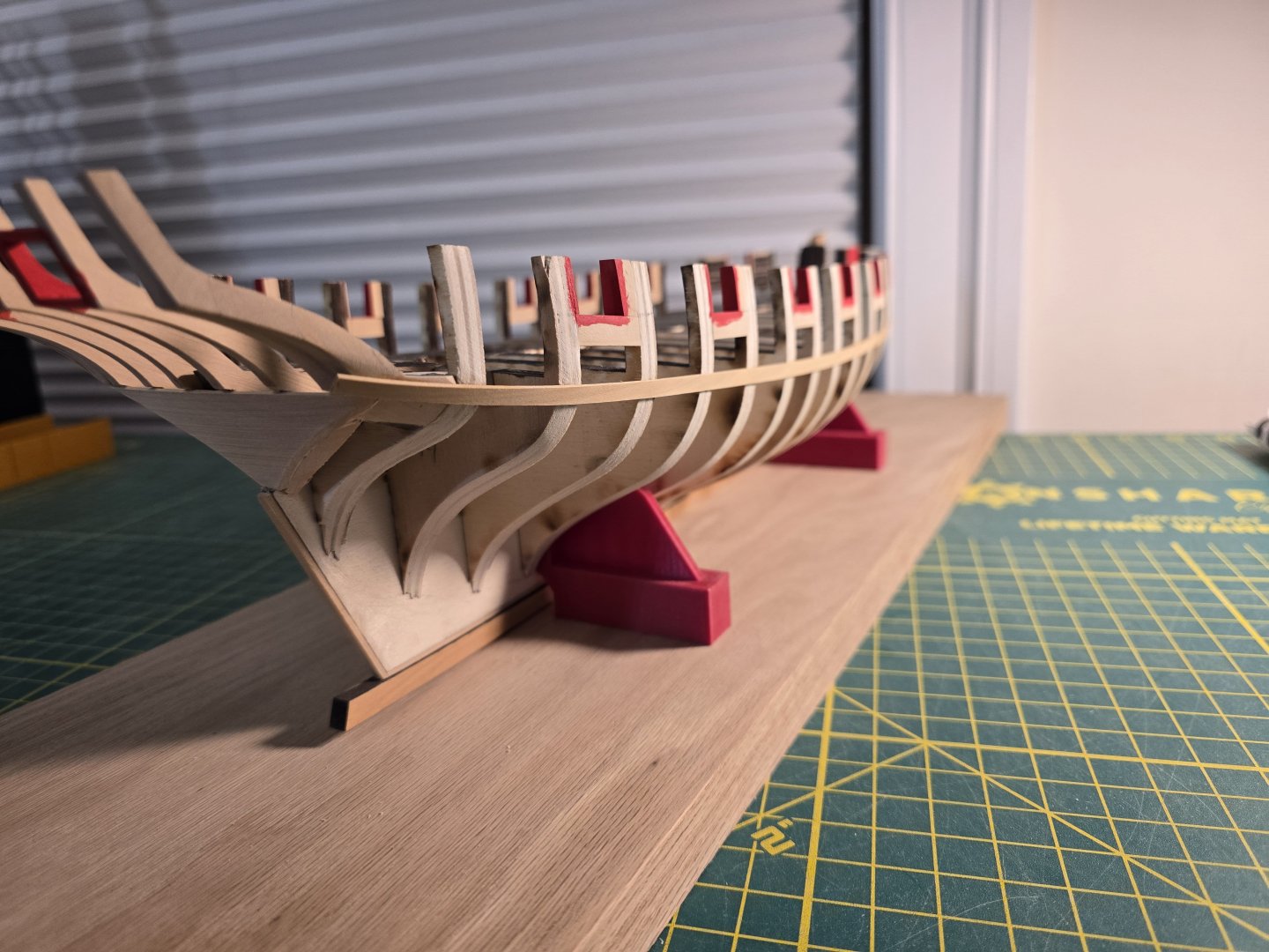
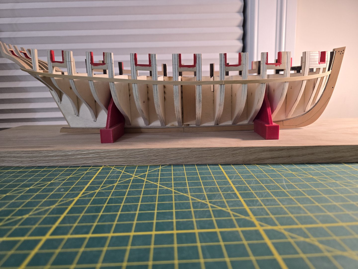
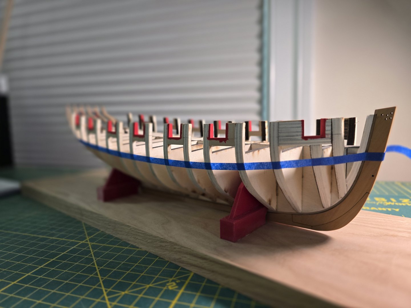
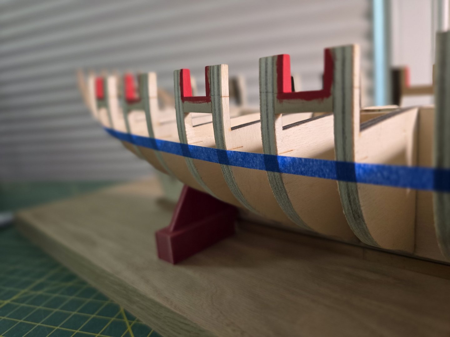
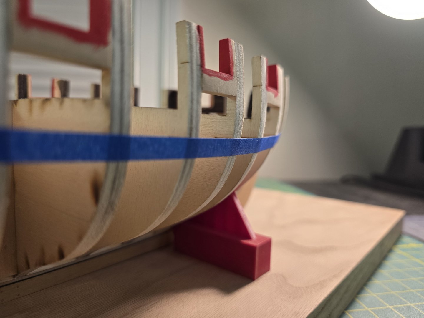
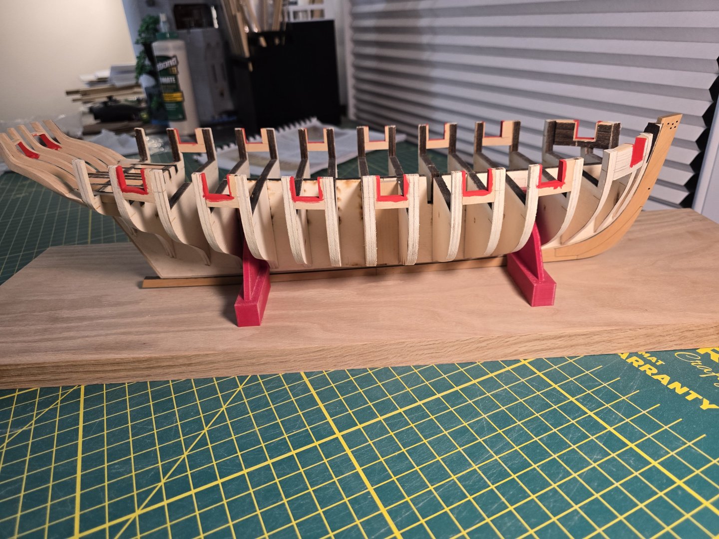
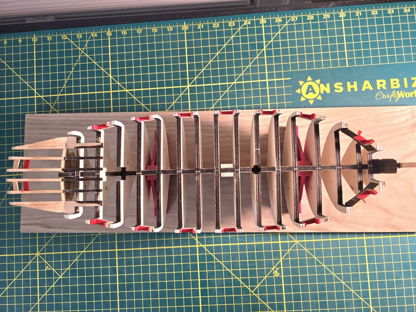
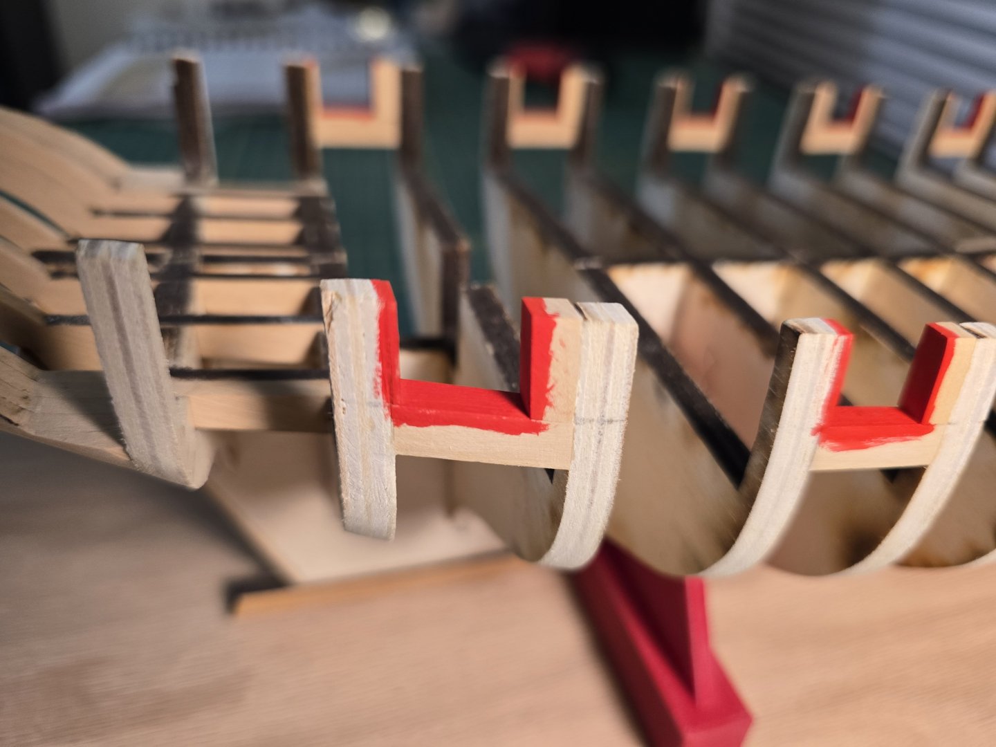
Thank you everyone for your nice comments and likes! They really help give me confidence in this build! Sorry for the delay. Between Halloween, working on my USF Confederacy, and work, I wanted to take a small break since I finished the framing. First off is a little painting. I used a normal brush i picked up at the local hobby store along with basic red paint. The color was called Pyrrole Red. I wanted to know what pyrrole meant so I looked it up. Of course it means a toxic chemical right? Haha! That freaked me out at first until i searched "Pyrrole Red" which is apparently an actual color. Whew! Anyway, I tried to paint each gunport in a thinner first layer. I had to thin it down with water since it's an acrylic paint, but I thought it came out pretty well. It might be hard to see, but after the first layer, there obviously are some spots that need to be gone over again. But with patience and some more watered down paint, I added 2 more layers and spot checked the painting work. With the painting out of the way, its time to mark where the wales will be located. I know i need to use a batten, but i usually use small tape strip to help line off the planks for gunports, wales, etc. You can see this in my above posts and in my Confederacy build log. (By the way, planking the gun ports on that ship sure takes a while!) Anyway, here are a few pics of me lining off the wales. I acutally do run a wood strip across the tape too, to gadge the curvature. But I can't really get pics of that since I only have 2 hands! When I first place the tape on each bulkhead, I try to line the tape up to each bulkhead line first. I don't care if it's the correct curve or not. I use that as the starting point to look at the tape curve in as many angles I can, like in the pics above. When looking closely at the curve, especially at an angle, it's really easy to spot any dips or bumps that need to be corrected. This can take a little bit of time. Once I make a correction to one bulkhead former tape position, I step back and look at the curve from multiple angles again. I continue this until I am satisfied with the curve. I always try and only focus on one side at first, then once I feel satisfied with its position, I move onto the other side so I can match the wale placement markings at the bow. For some reason, I was very surprised by this, I only had to modify 1-2 bulkhead former lines on each side. This is very unusual as for the Confederacy, I had to modify many bulkhead former line segments! After I was content with the curves on both sides, I would hold the tape on each bulkhead former when I marked the lines on the top of the tape. This will be a 2 post entry since they are different parts of the build I'm posting about. Next will be milling the first layer of the wales! Thanks all! Jeff


-
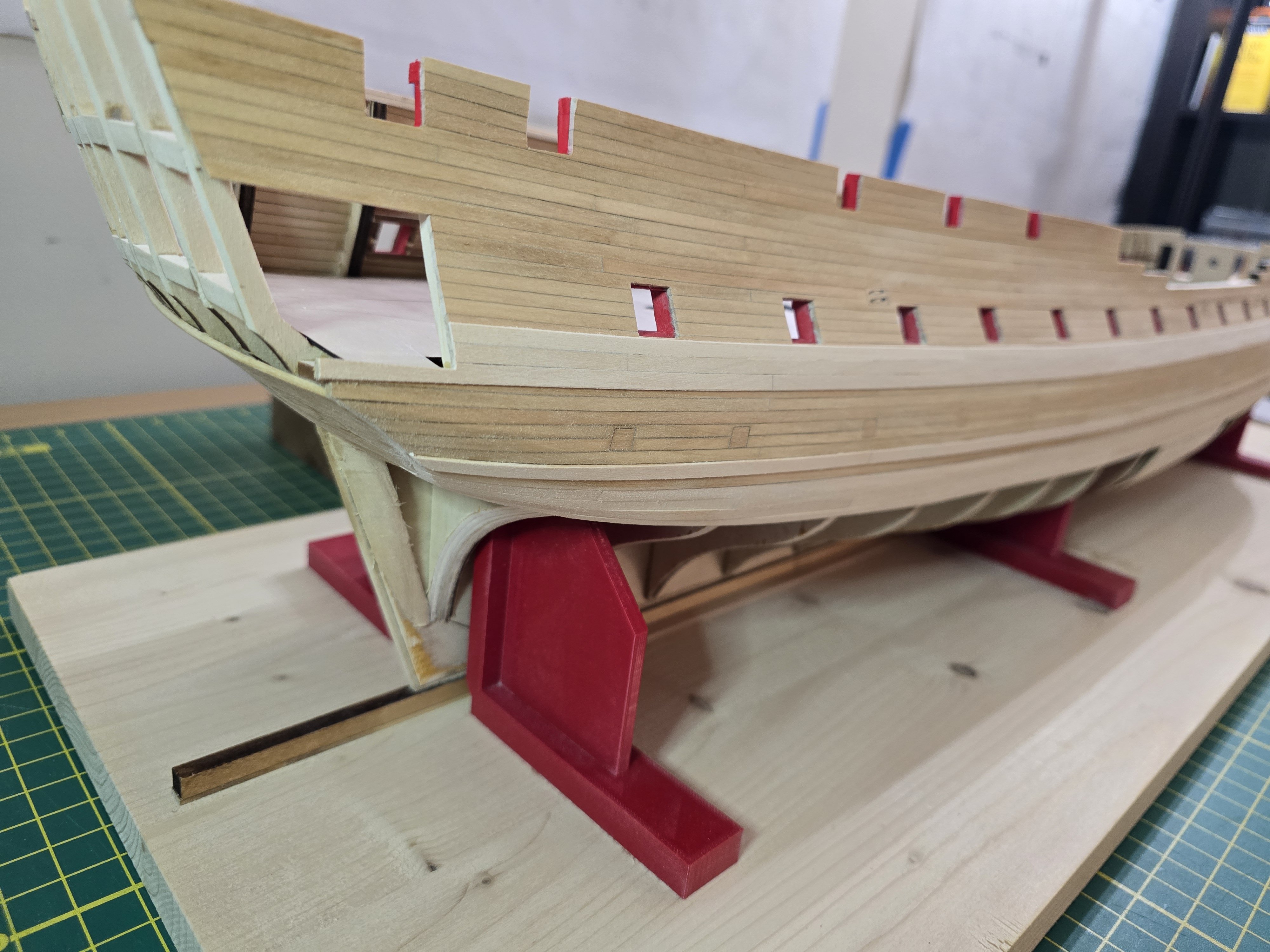
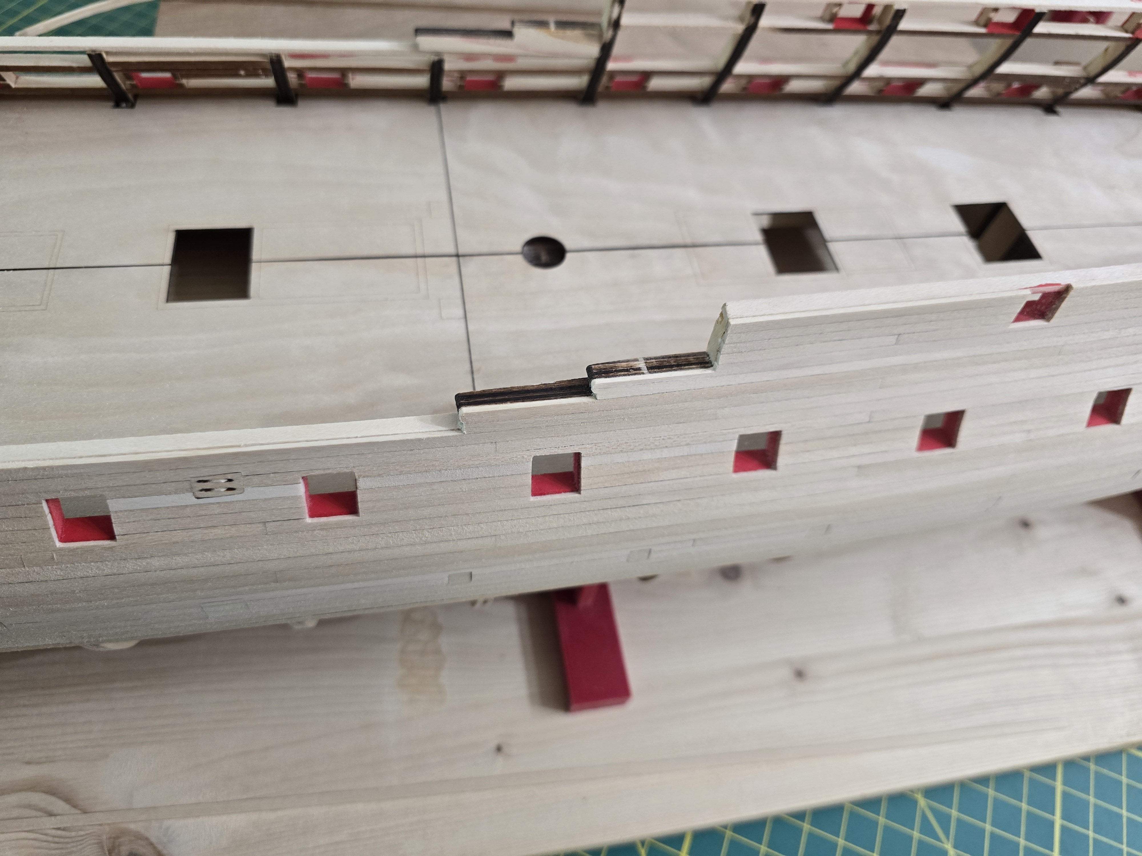
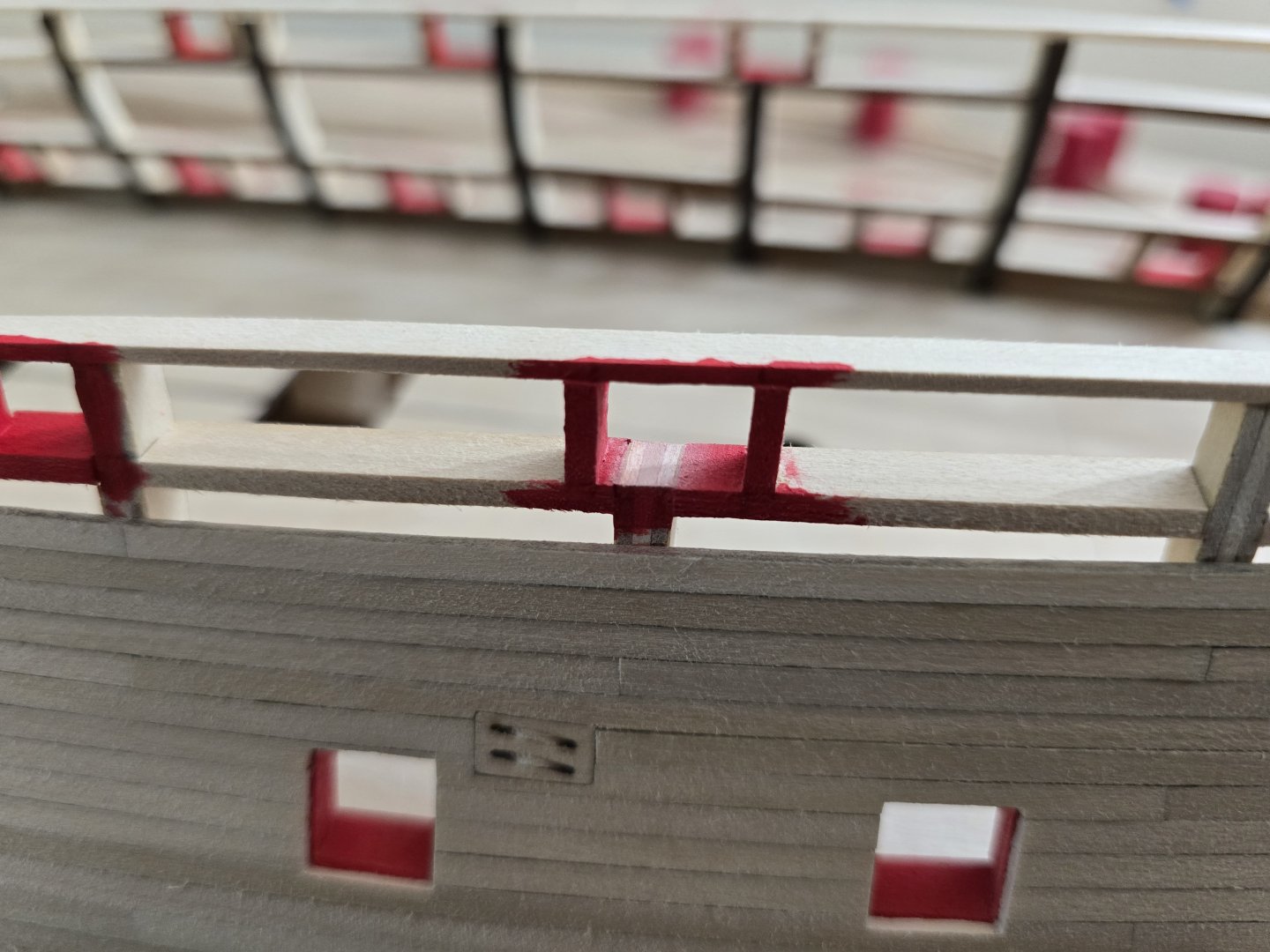
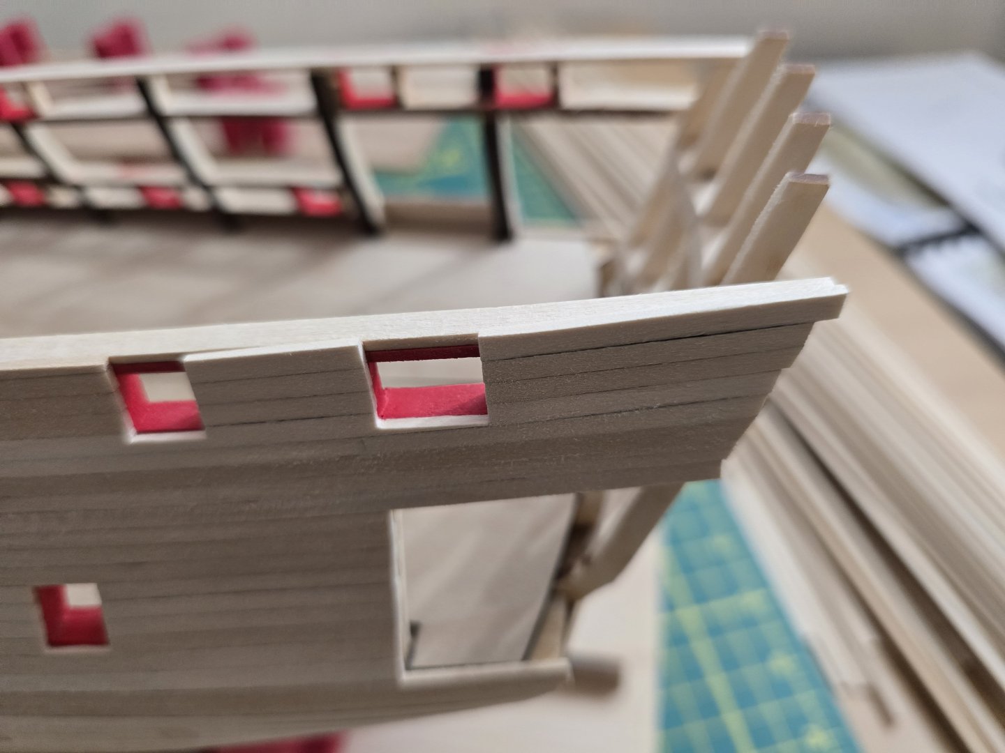
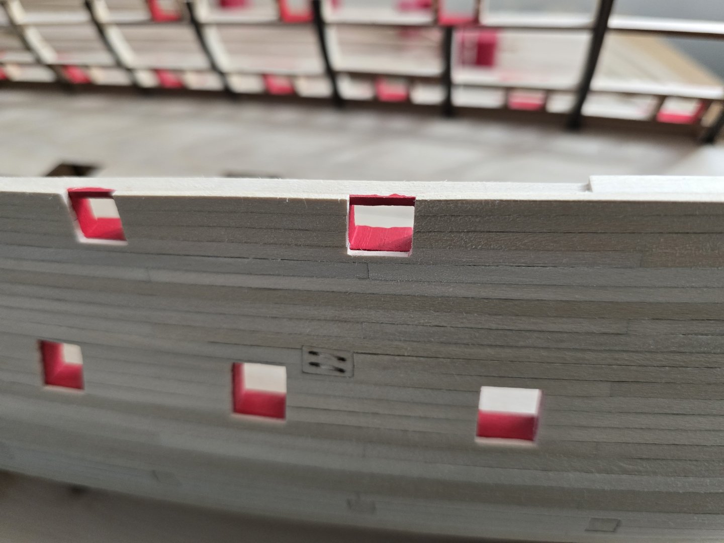
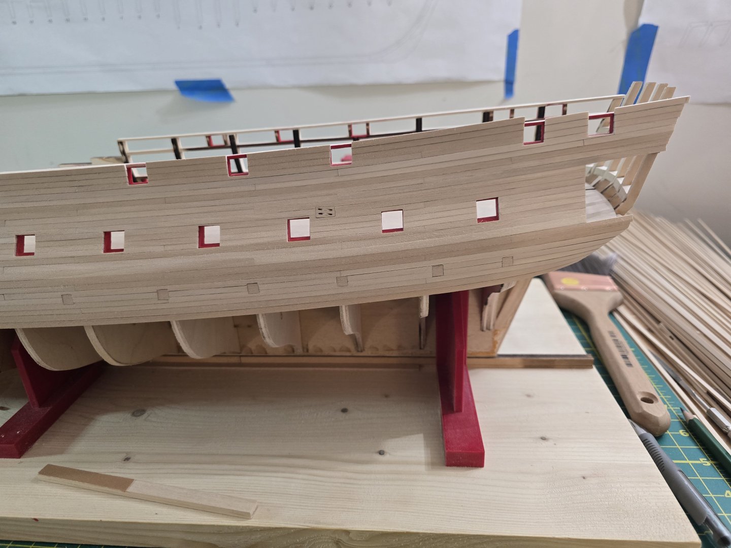
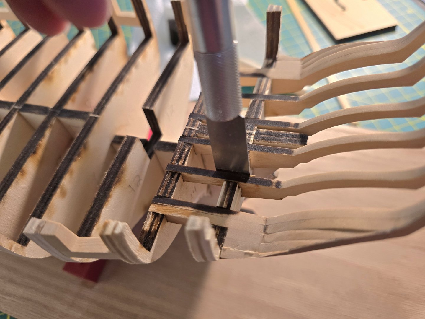
Hey all! I finally finished the side planking on one side! Well, other than the wales, painting, molding strips, etc. While planking up the hull, I noticed the aft most quarterdeck gunport had a "hole" on the sill. This is because it's where the laser cut pieces fit together, but not perfectly. You can see from the picture above, there is a space between the sill and the frame that I needed to fill. I took some wood filler I had from Occre and tried it out! After applying and letting it dry, I sanded it with 220 grit sandpaper. I then repainted it, and here was the result. I think it turned out really well! I completed the same steps on the other side of the ship since it had the same problem. I also had to sand down the other quarterdeck gunport which I had to cut the bulkhead out of. I realized I didn't sand it enough and the bulkhead plywood was very visible through the gunport sill. So as shown, I sanded it down. I then applied some wood filler and sanded / repainted. It now looks like this. It looks lot better. Again, I completed it on the other side as well. I also wanted to point out that the instructions say there should be 15, 1/8" x 1/16" planks to reach the top of the bulkhead formers. I had one area that took 16 strips. I'll show you below. Maybe I had too much of a curve for the planks? I don't know. But to fix it, I didn't have much of a choice but to do 2 things. I first added another lintel strip above the first one. The instructions do specify if need be, you can add another strip like this if your planking rises above the first lintel strip. I made sure to get a good fit and glued the second lintel strip ontop of the first while also gluing it to the hull plank it touches. I didn't need to make it very long. I only made it long enough to match the planks that needed the extra support. I then needed to make sure I had a good gentle curve so I taped a batten to the 15th strip like so. I then marked where I needed to take off the top plank and sanded it down to make sure it has a nice curve. To make sure i had a good curve, i placed a strip where the cap rail would be and made sure there weren't dips or bulges. I know it's not perfect, but it will be pained black anyway later in the build so I wasn't too worried about it. Here is what the side looks like currently. Please let me know what you guys think! Now it's time to start the other side. Thanks! Jeff


-
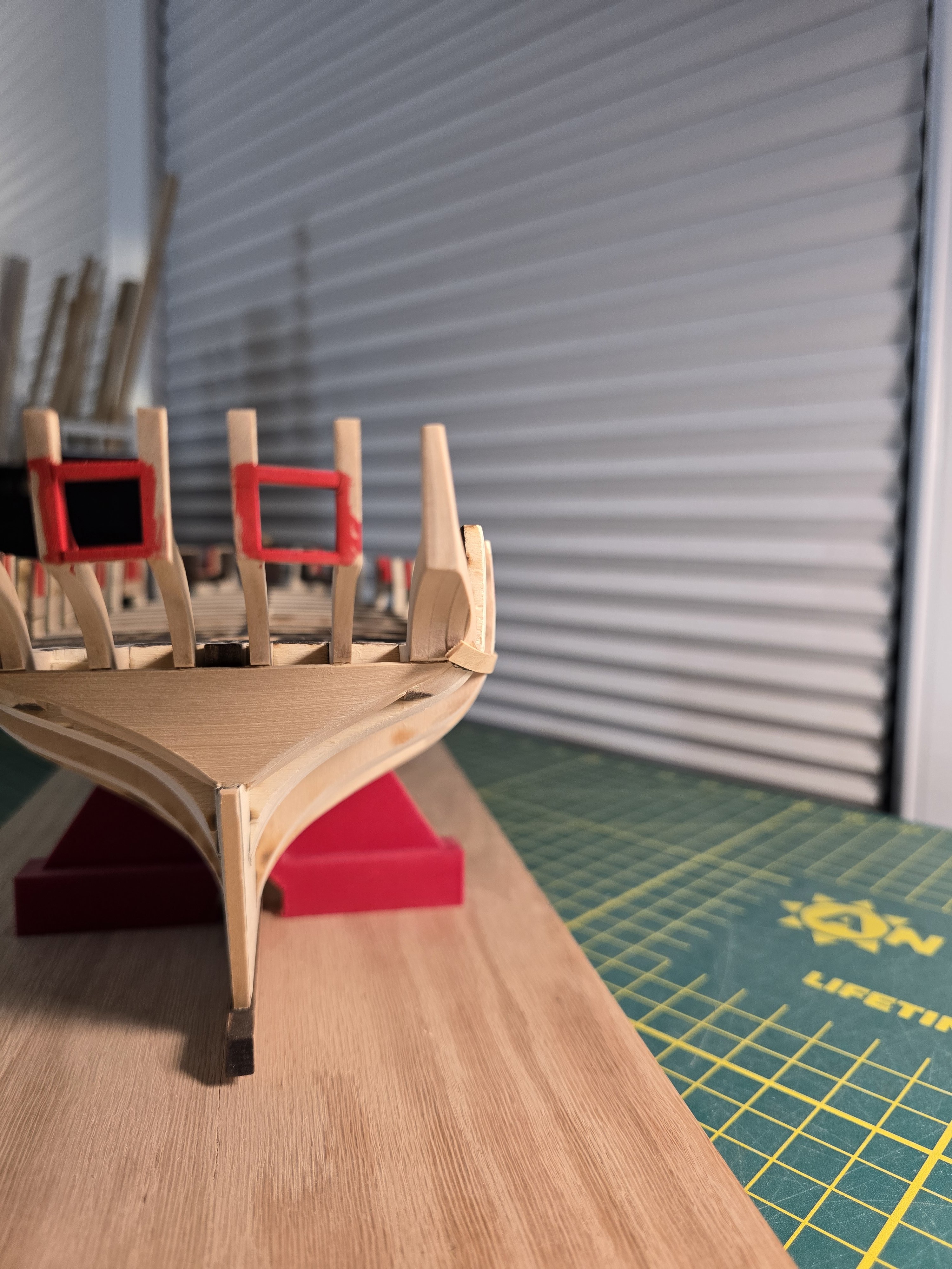
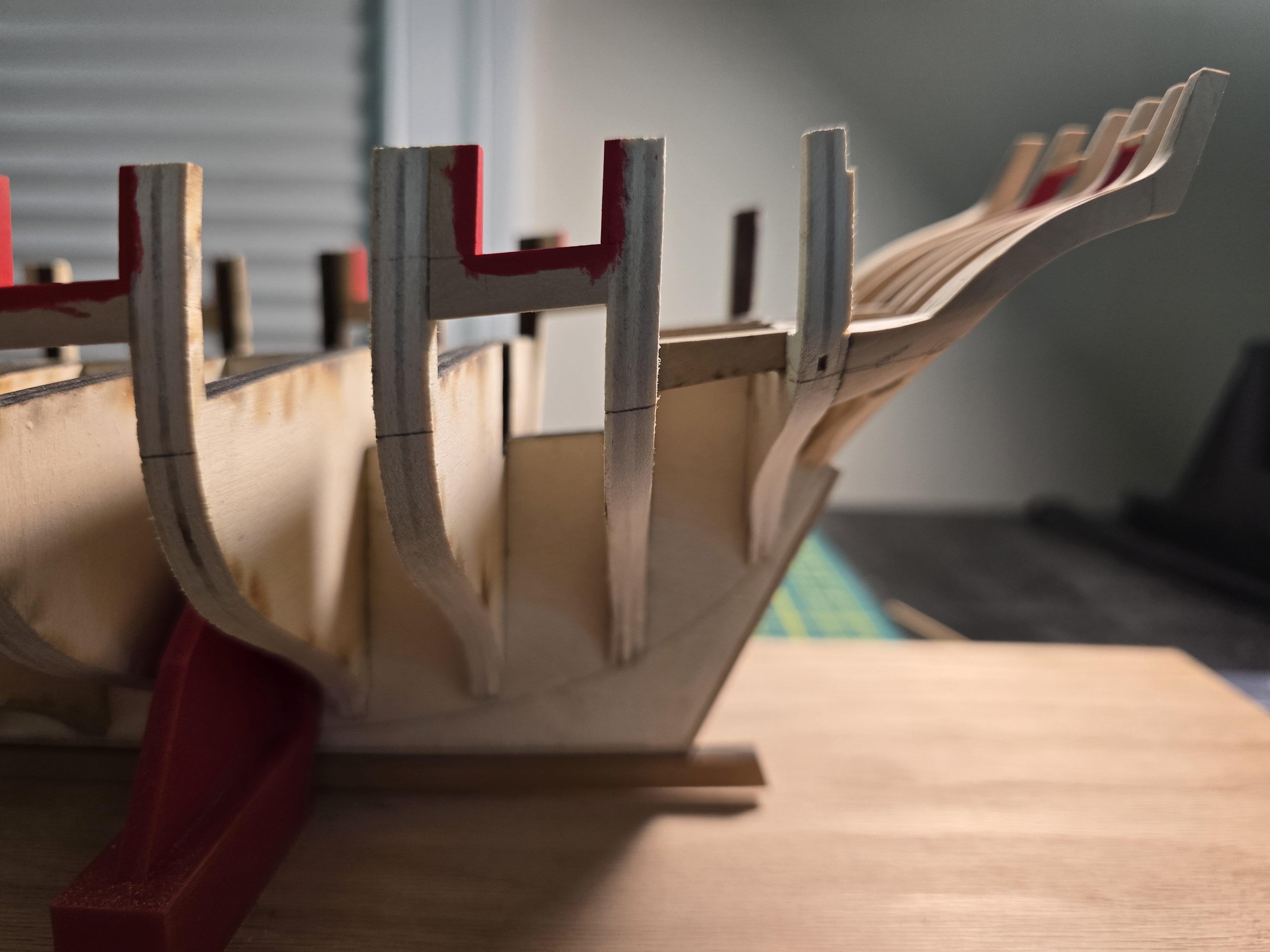
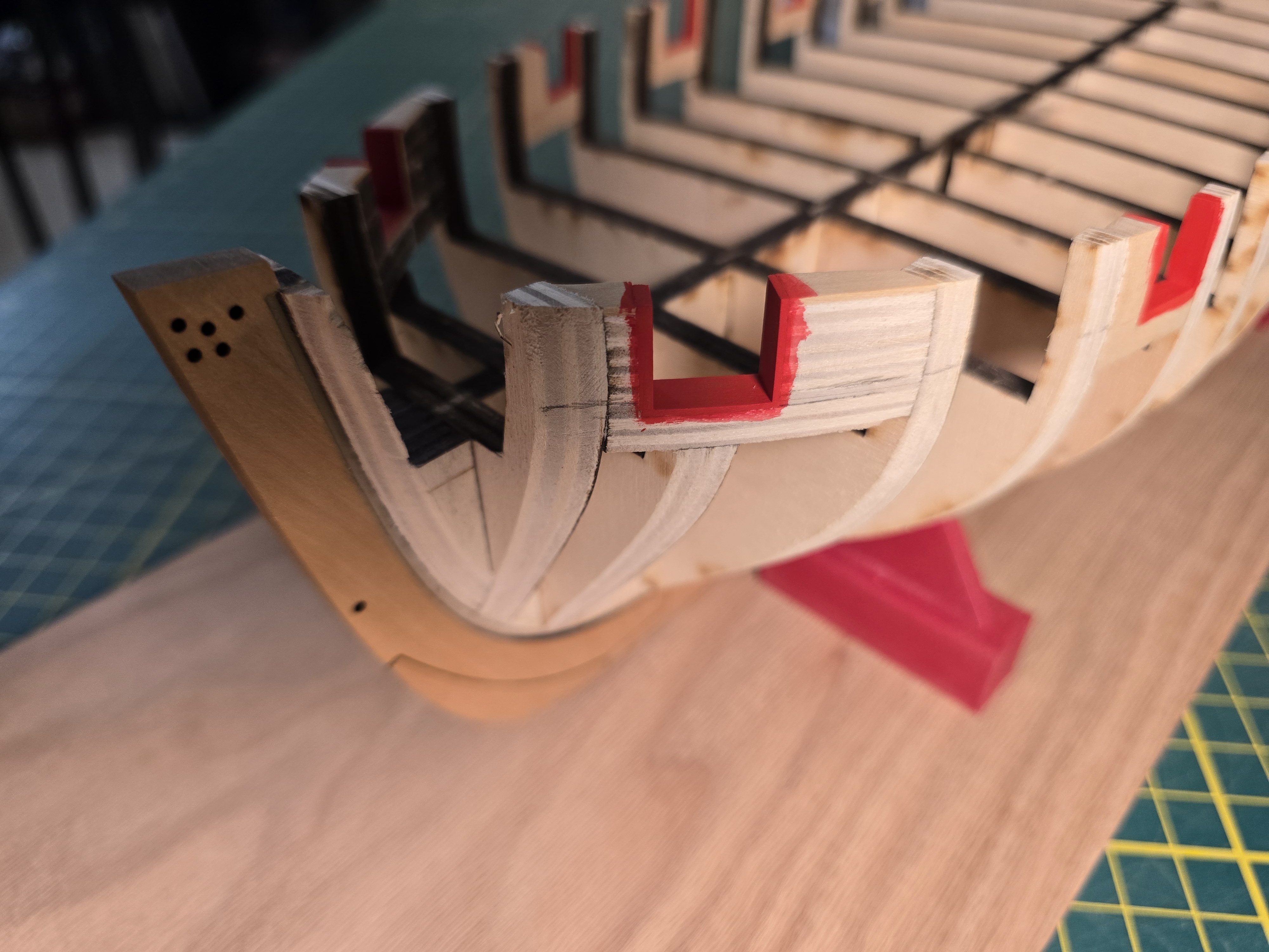
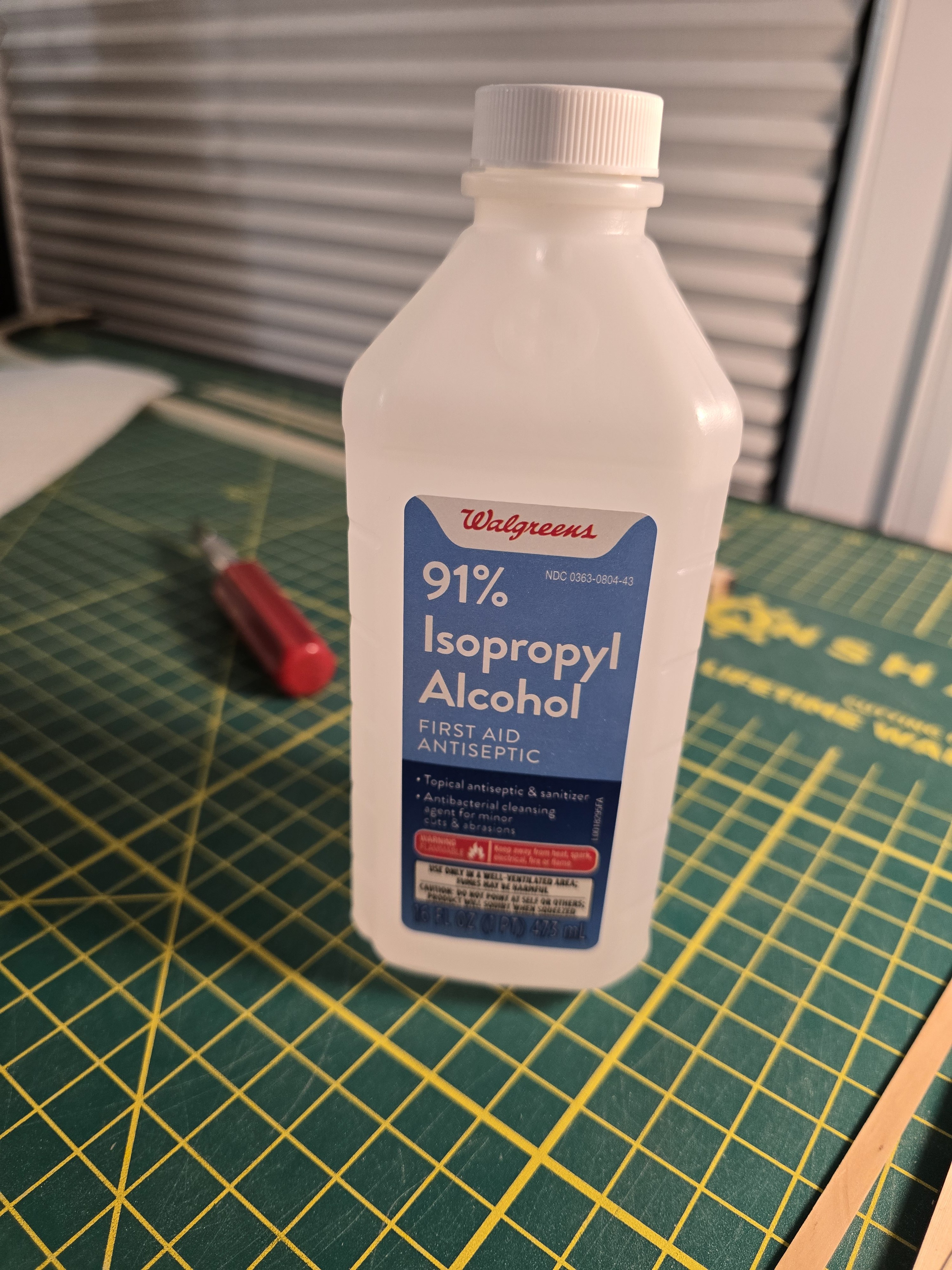
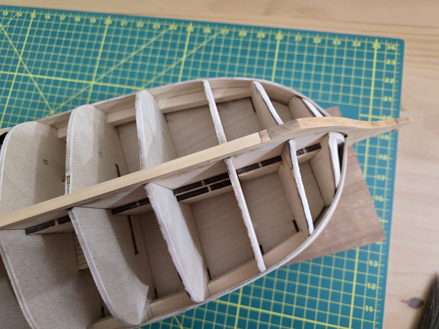
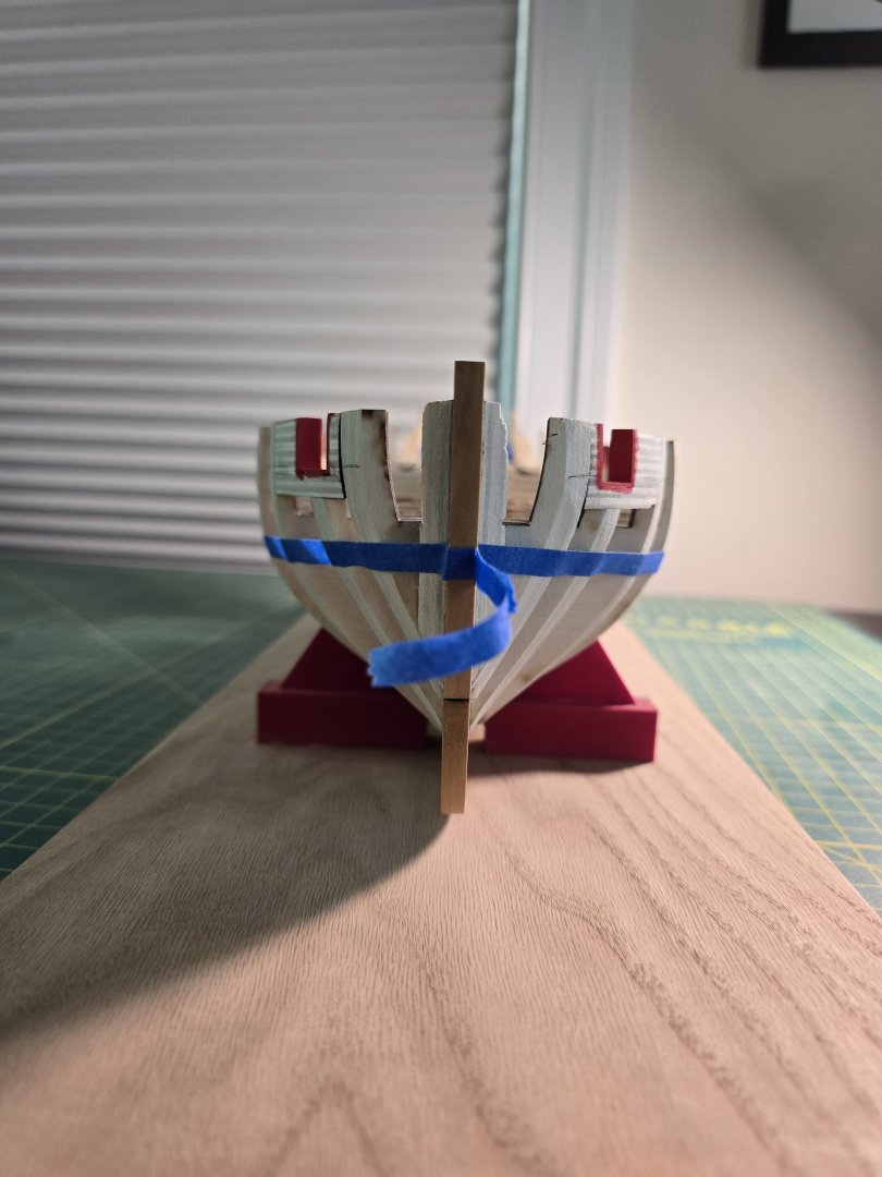
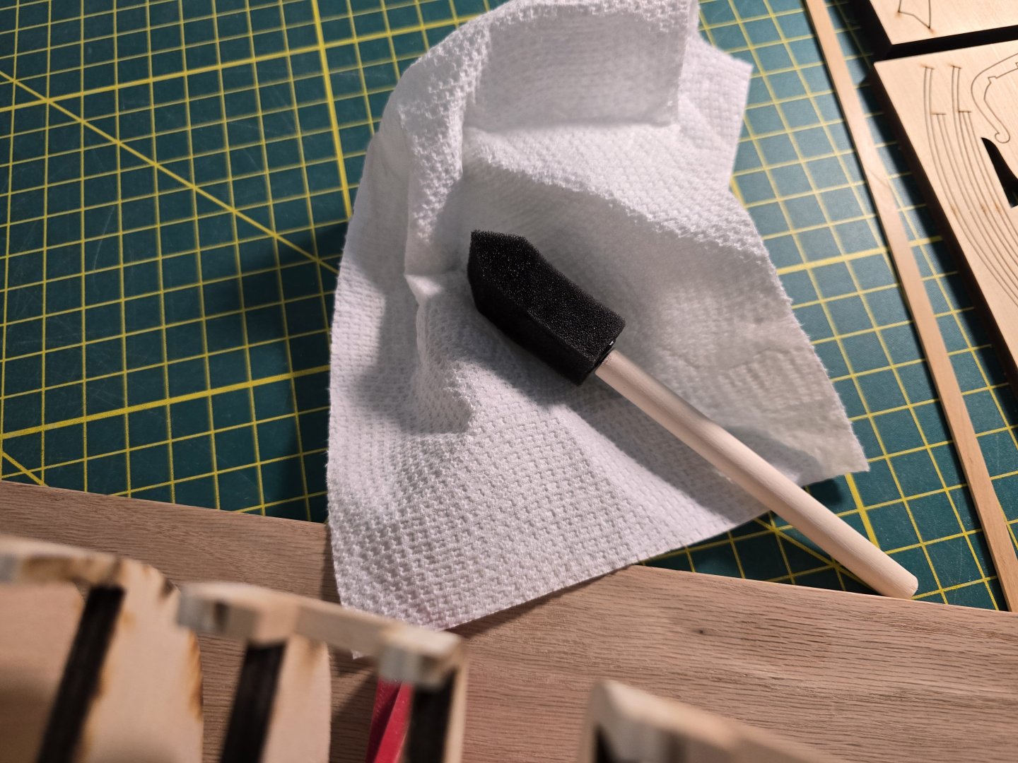
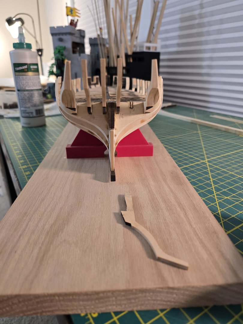
Thank you Paul! I appreciate your feedback! Today I had an issue. I realized that the Y stern pieces were not in the correct orientation. Notice the second frame from the front (Y) is too low. I will have to remove both Y pieces and reglue them. I had used wood glue for these parts so this is how I removed the part without breaking anything. I took some 91% alcohol and dipped a foam brush in it. The foam brush soaks up the alcohol very well! So I touched the 2 points where the stern Y piece is glued to the bulkhead formers with just the corner of the foam brush. I made sure the alcohol covered all the joints well. I then let it sit for about 10 seconds or so then CAREFULLY placed my razor blade onto the sides of the aft most joint. I slowly with little pressure moved the blade back and forth going deeper into the joint. I did this on both sides of the joint. The trick is to not push very hard. The piece then wad able to be lifted off the model. The second photo is when I took the other Y frame out to reposition it. I waited for the pieces to dry from the alcohol and lightly sanded the glue off. Lastly, I re-glued the pieces back but in the correct position. Whew! I wanted to make sure all the stern frames were in the correct positions before moving onto making the port sills and lintels. Thanks all! Jeff


-
Ronald, I agree with you. I feel the same as to not rush things. This is a hobby to relax with. Not only that, rushing only makes my work look sloppy ( I know from my own experience!) Nearshore, thank you for the compliment! This Confederacy kit is single planked. The only time in the kit where it's double planked are for the wales and molding strips. That's why I'm really trying to take my time with it to get the best results I can with my skills level. Thanks! Jeff