SardonicMeow
-
Posts
333 -
Joined
-
Last visited
7 Followers


.thumb.jpg.62d1d69fed1f32364417cb1f9cdeb009.jpg)

About SardonicMeow

-
 ExiledArtist reacted to a post in a topic:
Amanda F Lewis 1884 by SardonicMeow - Scale 1:48 - Chesapeake Bay pungy
ExiledArtist reacted to a post in a topic:
Amanda F Lewis 1884 by SardonicMeow - Scale 1:48 - Chesapeake Bay pungy
-
ExiledArtist reacted to a post in a topic:
Amanda F Lewis 1884 by SardonicMeow - Scale 1:48 - Chesapeake Bay pungy
-
ExiledArtist reacted to a post in a topic:
Amanda F Lewis 1884 by SardonicMeow - Scale 1:48 - Chesapeake Bay pungy
-
ExiledArtist reacted to a post in a topic:
Amanda F Lewis 1884 by SardonicMeow - Scale 1:48 - Chesapeake Bay pungy
-
grsjax reacted to a post in a topic:
Sultana by SardonicMeow - FINISHED - Model Shipways - Scale 1:64
-
Sterling59 reacted to a post in a topic:
Some silkspan tips
-
MAGIC's Craig reacted to a post in a topic:
Amanda F Lewis 1884 by SardonicMeow - Scale 1:48 - Chesapeake Bay pungy
-
yvesvidal reacted to a post in a topic:
Amanda F Lewis 1884 by SardonicMeow - Scale 1:48 - Chesapeake Bay pungy
-
yvesvidal reacted to a post in a topic:
Amanda F Lewis 1884 by SardonicMeow - Scale 1:48 - Chesapeake Bay pungy
-
yvesvidal reacted to a post in a topic:
Amanda F Lewis 1884 by SardonicMeow - Scale 1:48 - Chesapeake Bay pungy
-
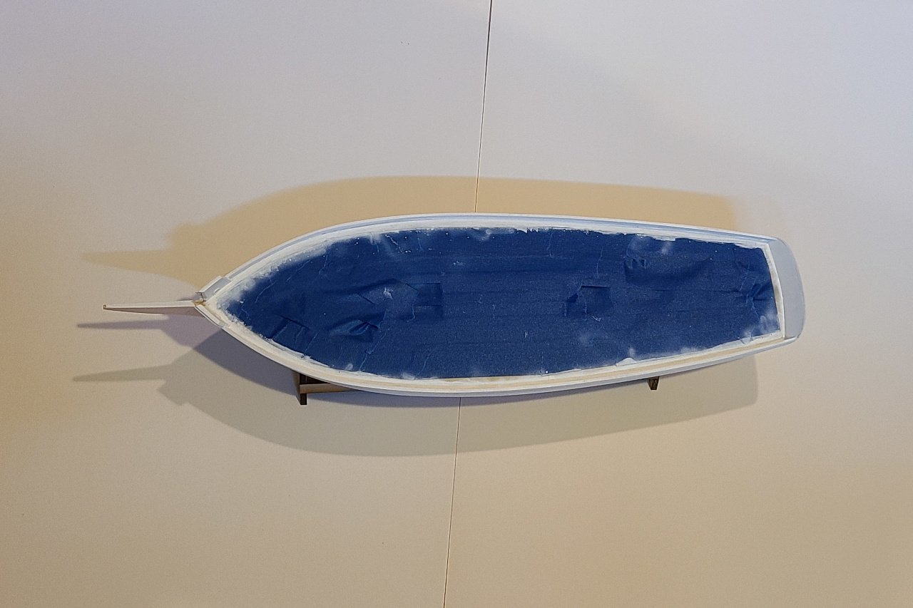
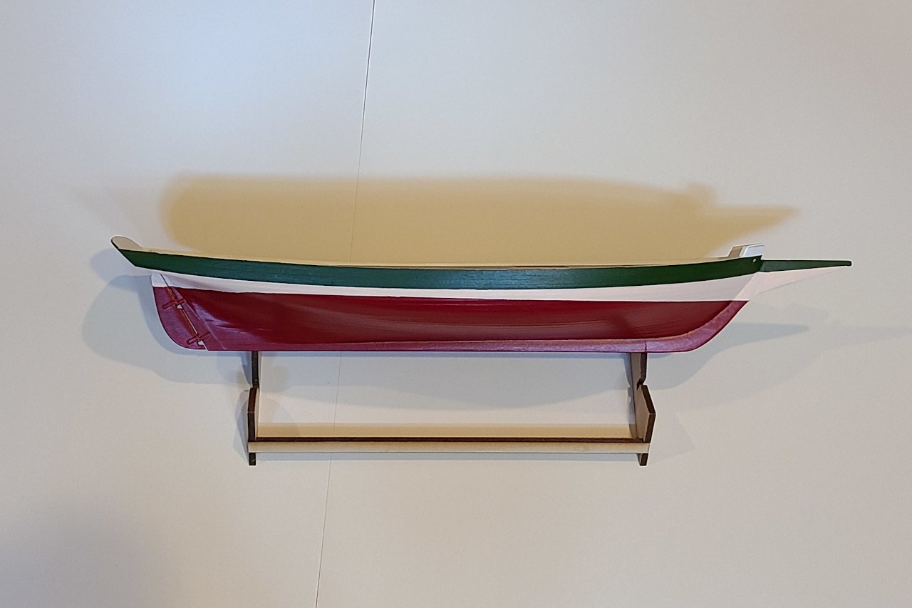
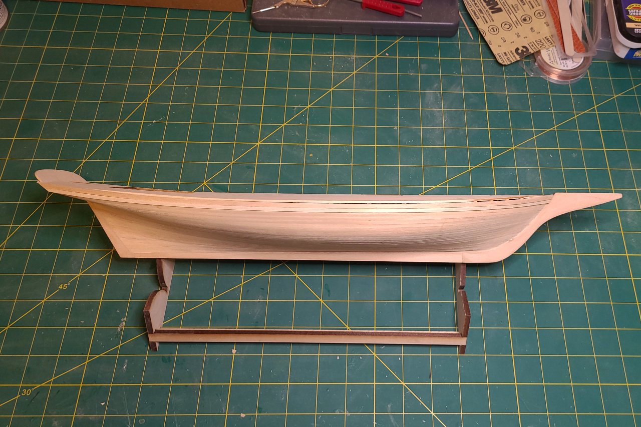
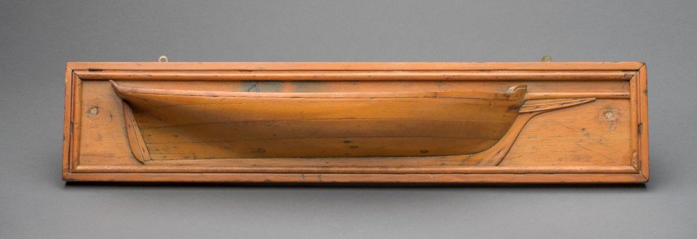
 Painting a pungy Pungies were traditionally painted green, pink, and red, as shown below. The waterways and rails were painted white. Above: Half-hull model of the Amanda F Lewis, constructed by William E. Geoghegan circa 1954 Image source: The Mariner’s Museum, retrieved from https://catalogs.marinersmuseum.org/object/CL24945 For most of her life, the Amanda F. Lewis was painted this way. However, in the 1930s, her owner was unable to find the traditional pigments, and she was painted grey above and white below. The painting in the first entry of this build log shows this paint scheme. In theory, I could have a historically accurate model if I painted it the same way. But, of course, the traditional colors are too nice not to use. The green color was called “bronze green”, sometimes described as bottle green. It was mixed from dark blue, raw sienna, and vermilion. I found a paint using chromium sesquioxide pigment that is sufficiently close. The pink was described as “flesh” color and was made from white, vermilion, and raw sienna. For some reason, no one sells paint in “pungy pink”, so I had to mix my own, and I followed the traditional recipe. I started by adding a little red to white, and ended up with a pink that looked like strawberry ice cream. After adding the raw sienna (much more raw sienna than red), I achieved a color that I think is pretty close to authentic. The red color on the bottom of the hull was “vermilion”, and I found a crimson color that looks good to me. The deck was taped off and everything received a coat of white. Then pungy pink on the bottom. More tape was added and the green and red were painted. (And I forgot to take pictures at this stage.) After all the tape was removed, and some touch-ups applied: View from above And from the side
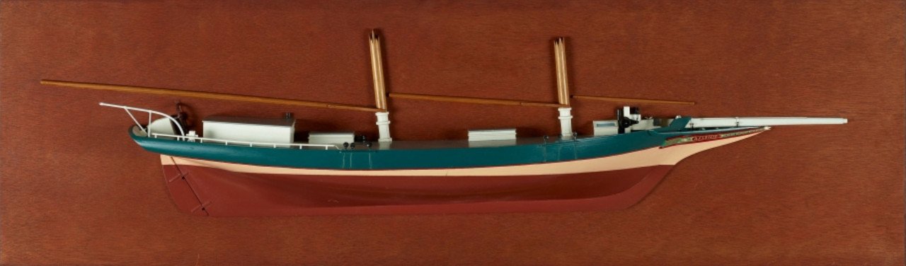
-
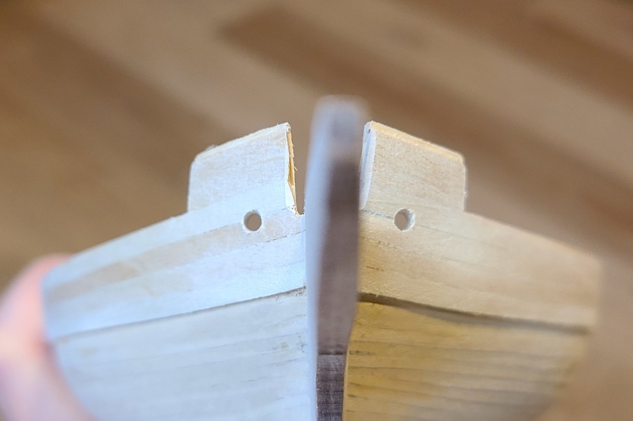
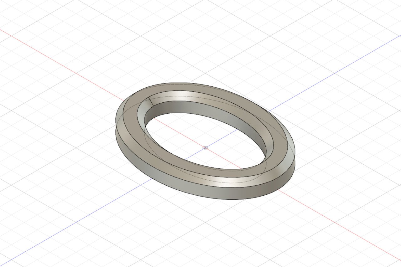
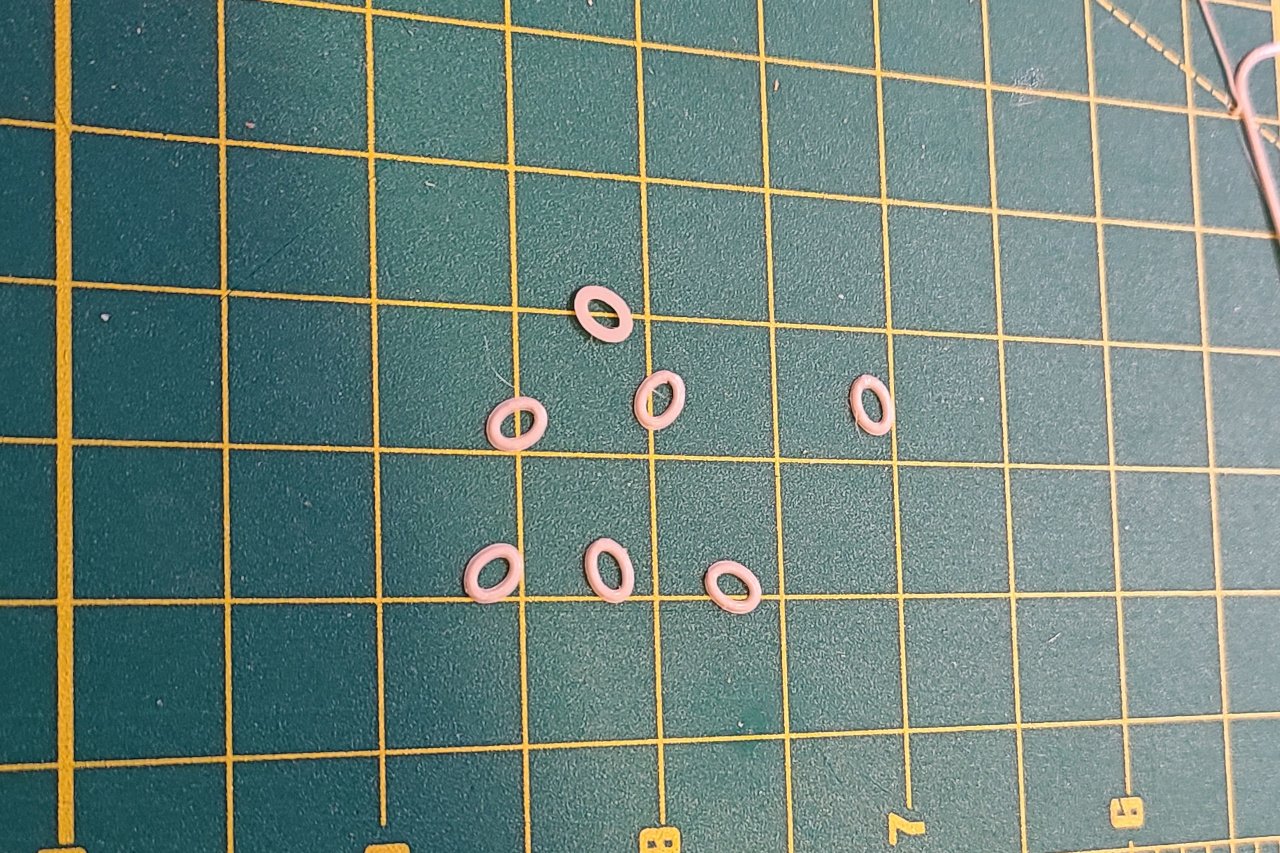
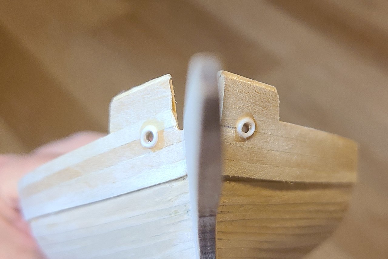
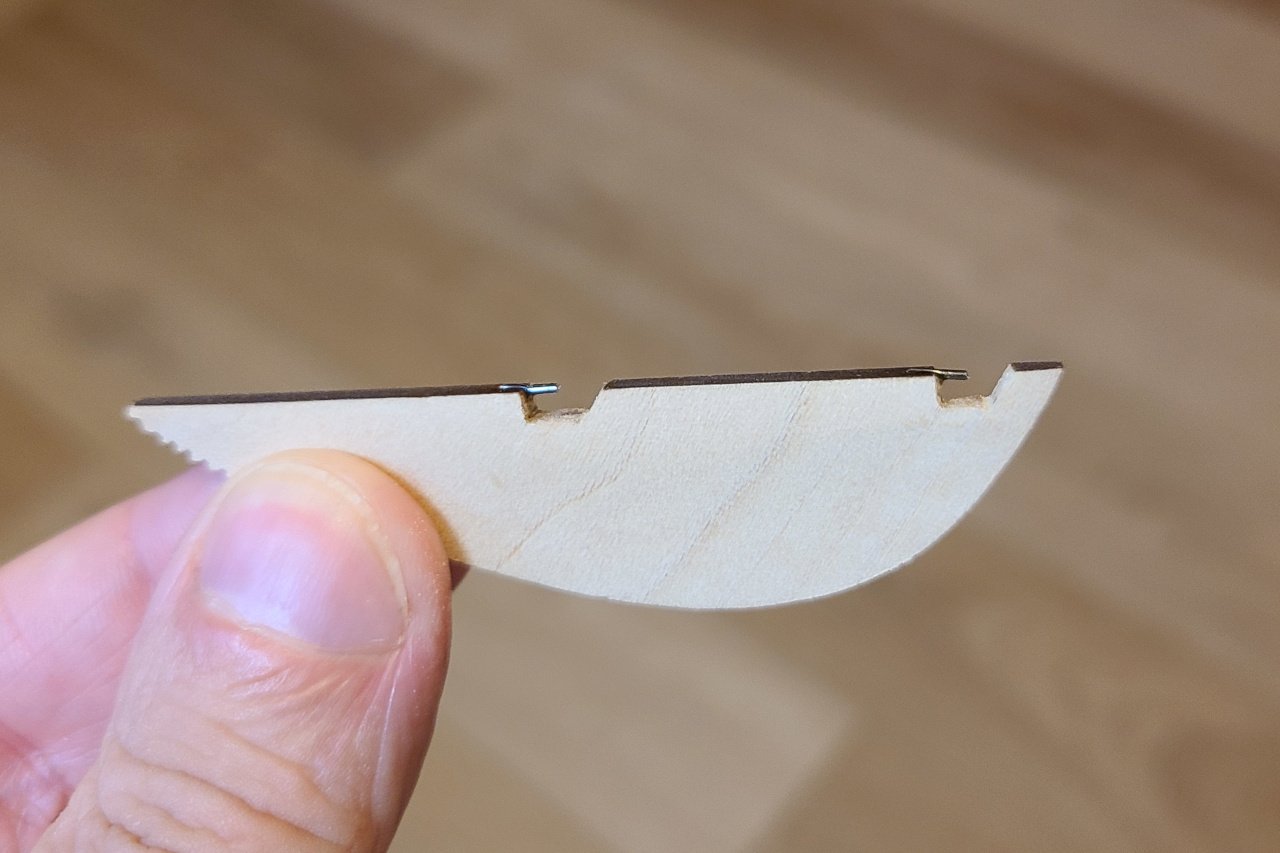
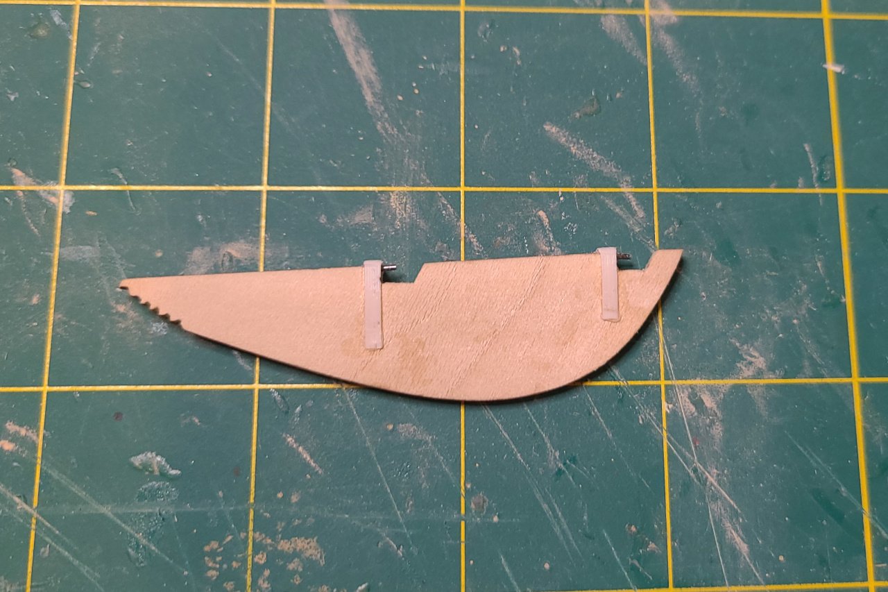
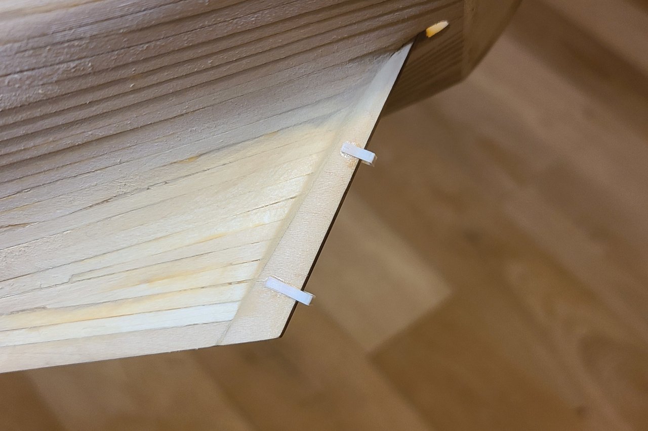
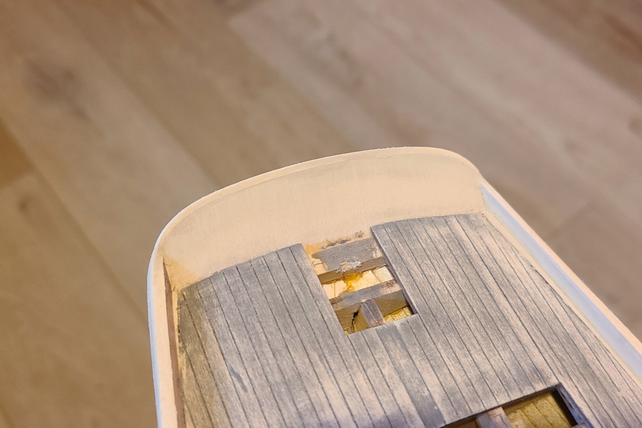
The hawse holes were drilled through. And a 3D part was designed to go on the hawse holes. I printed multiple because there are sometimes a few duds. Glued in place. And on the inside too. Pins were added to the rudder. And straps to make the pintles. 3D printed gudgeons. And all of it put together. All of this will be painted, so color and glue stains don't matter.
-
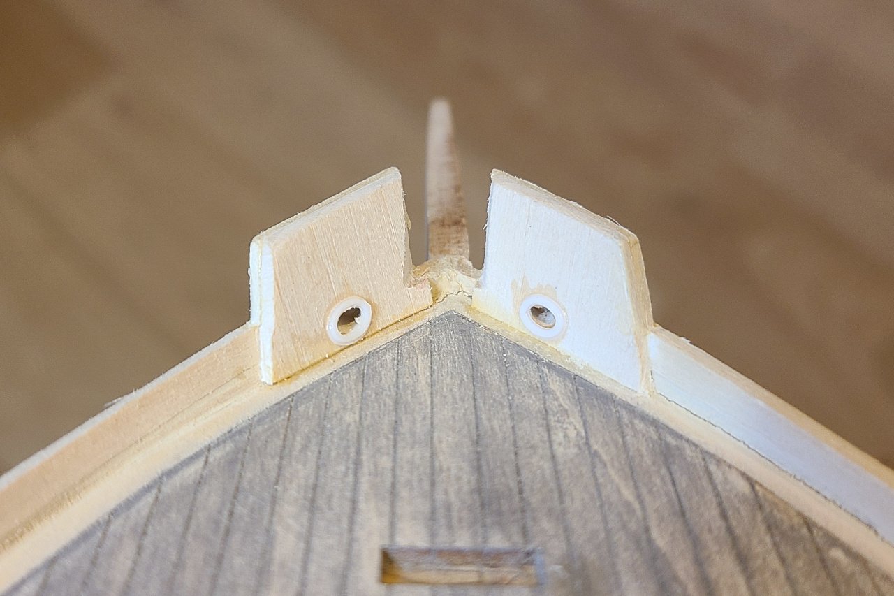
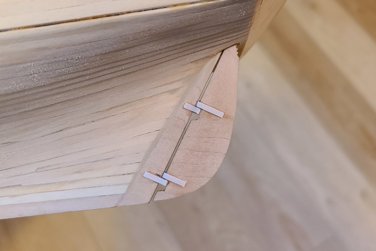
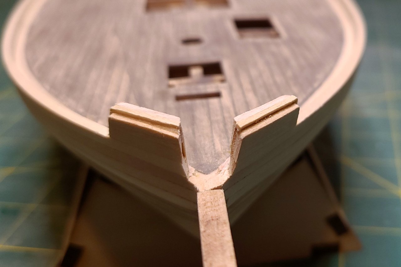
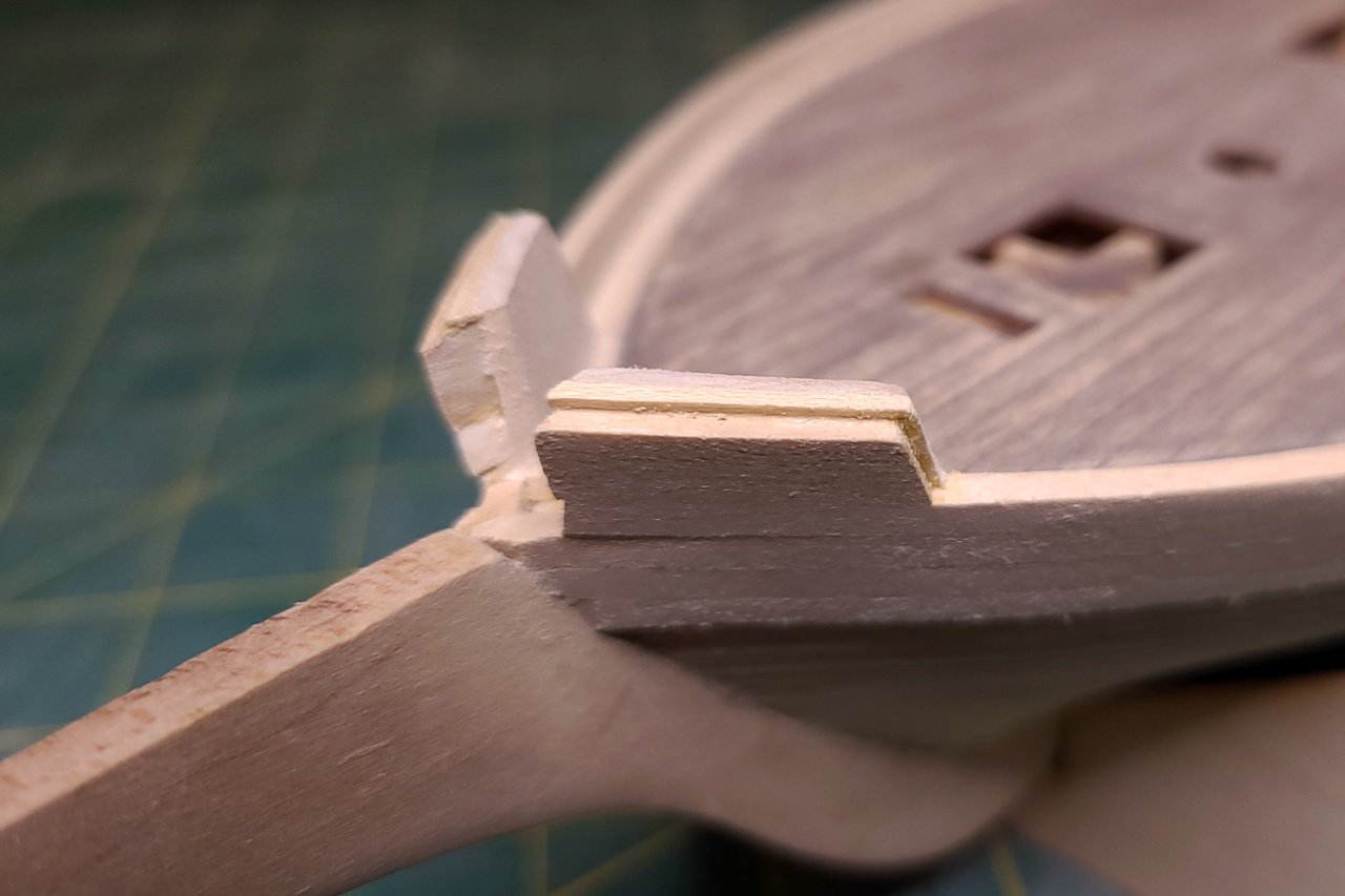
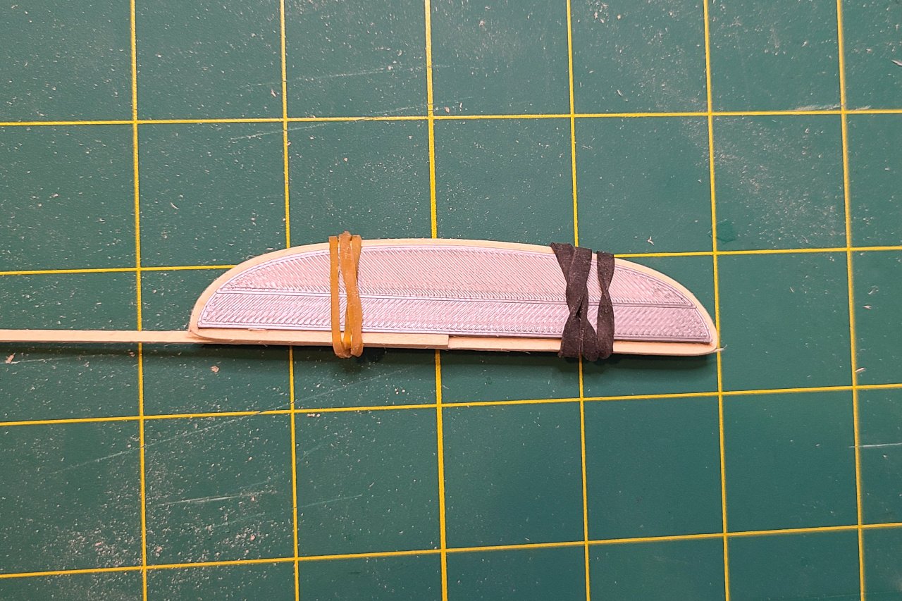
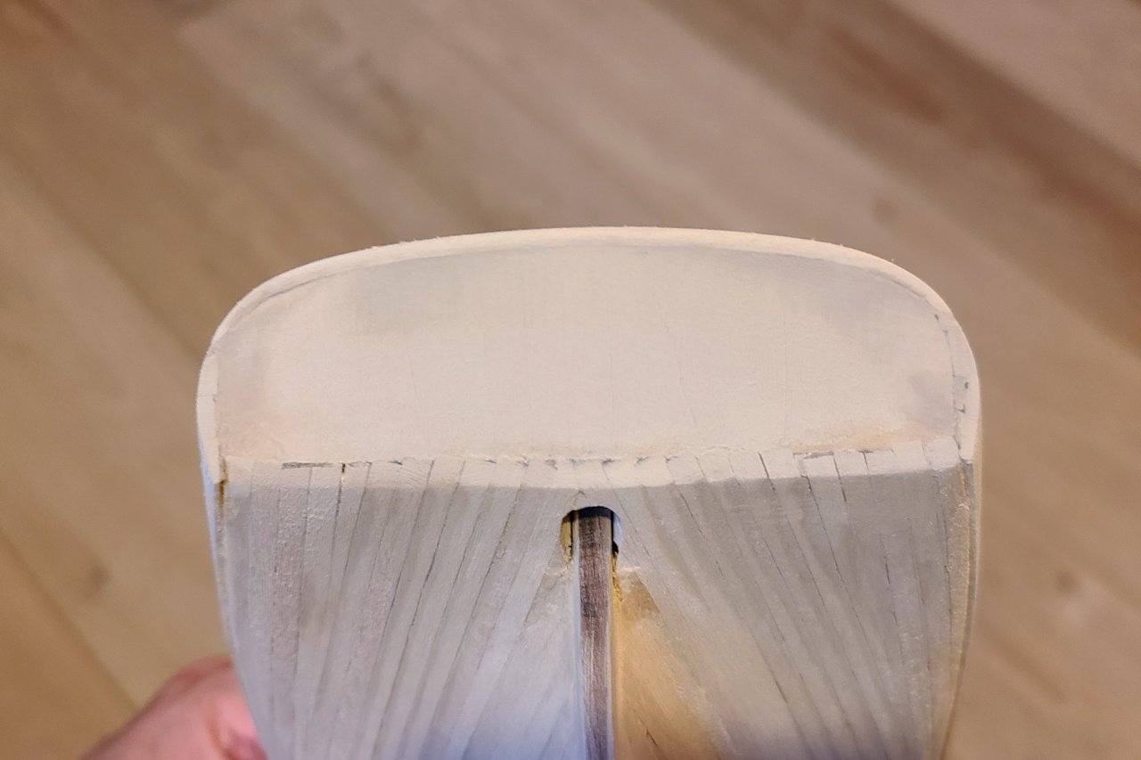
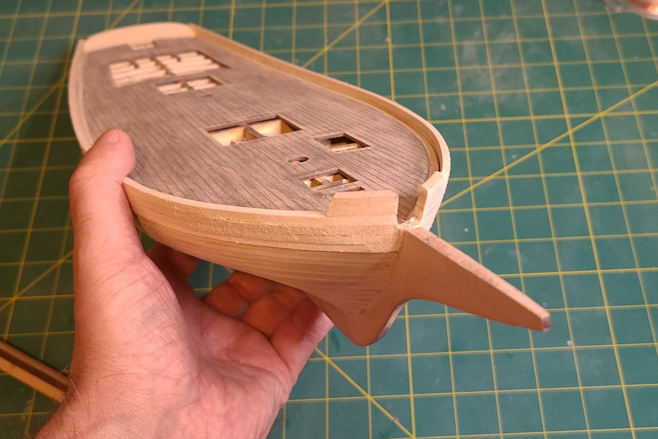
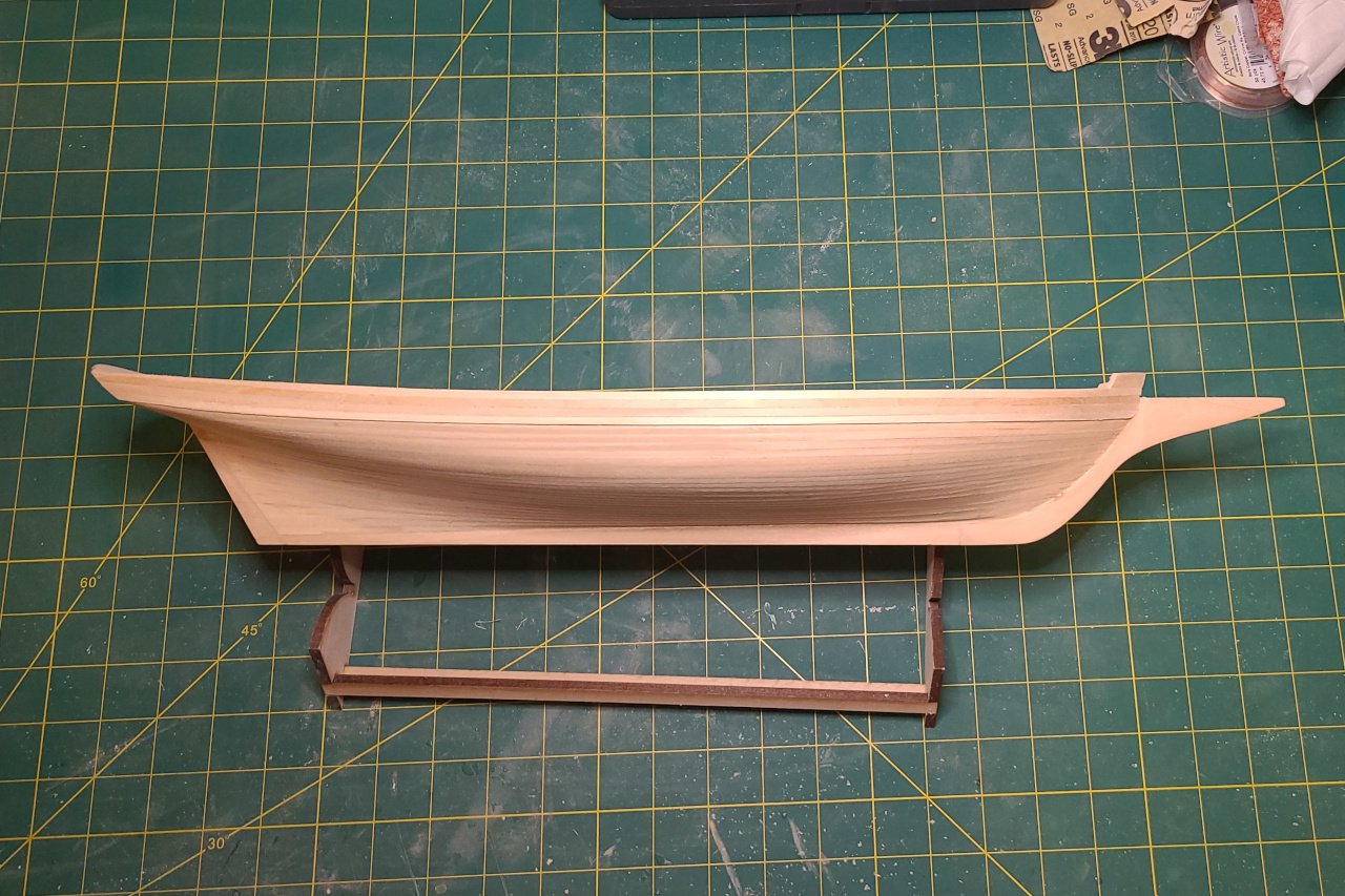
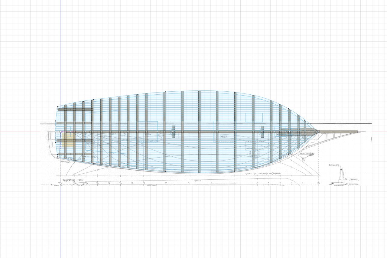
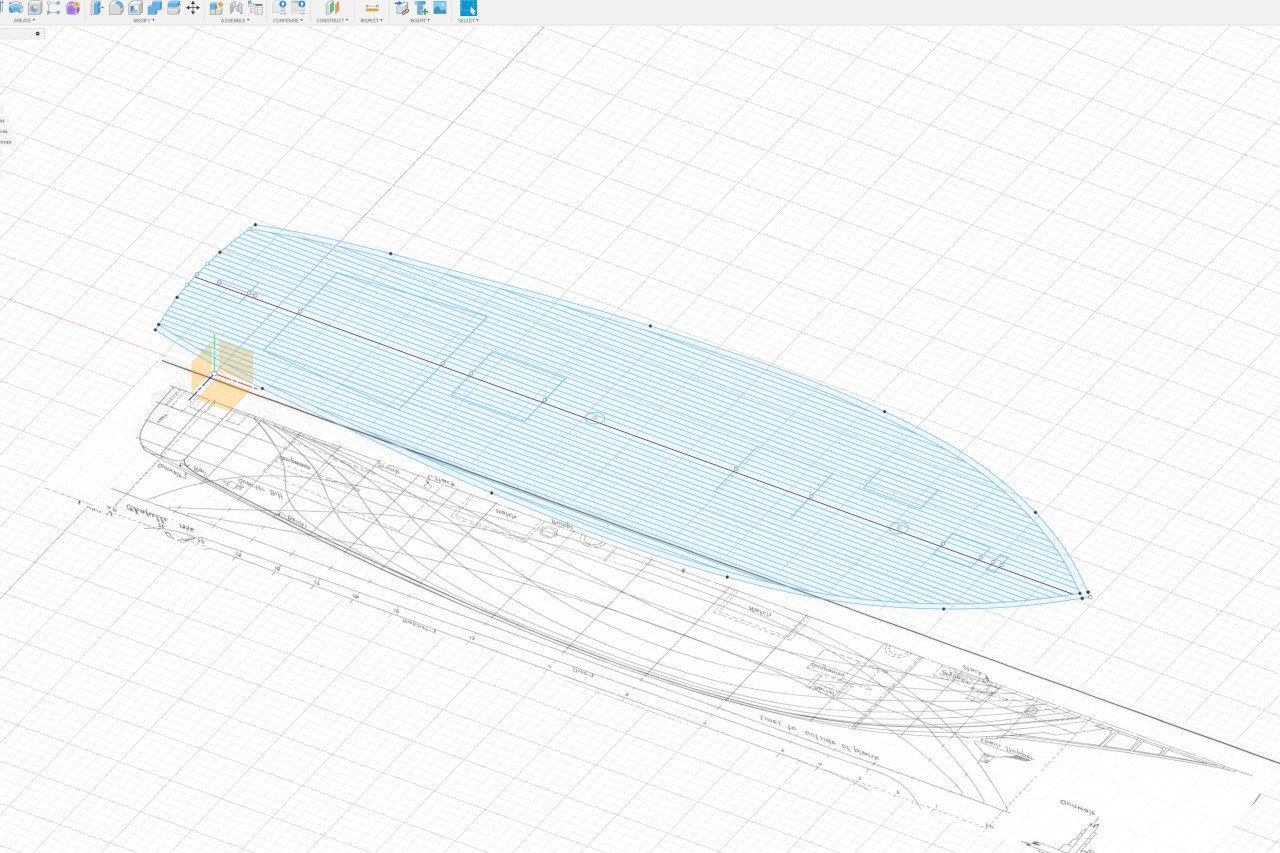
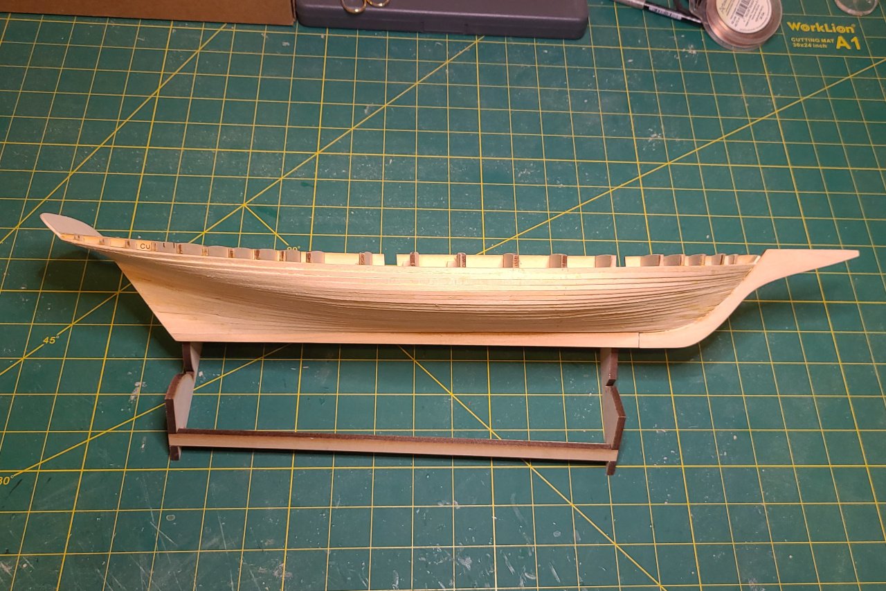
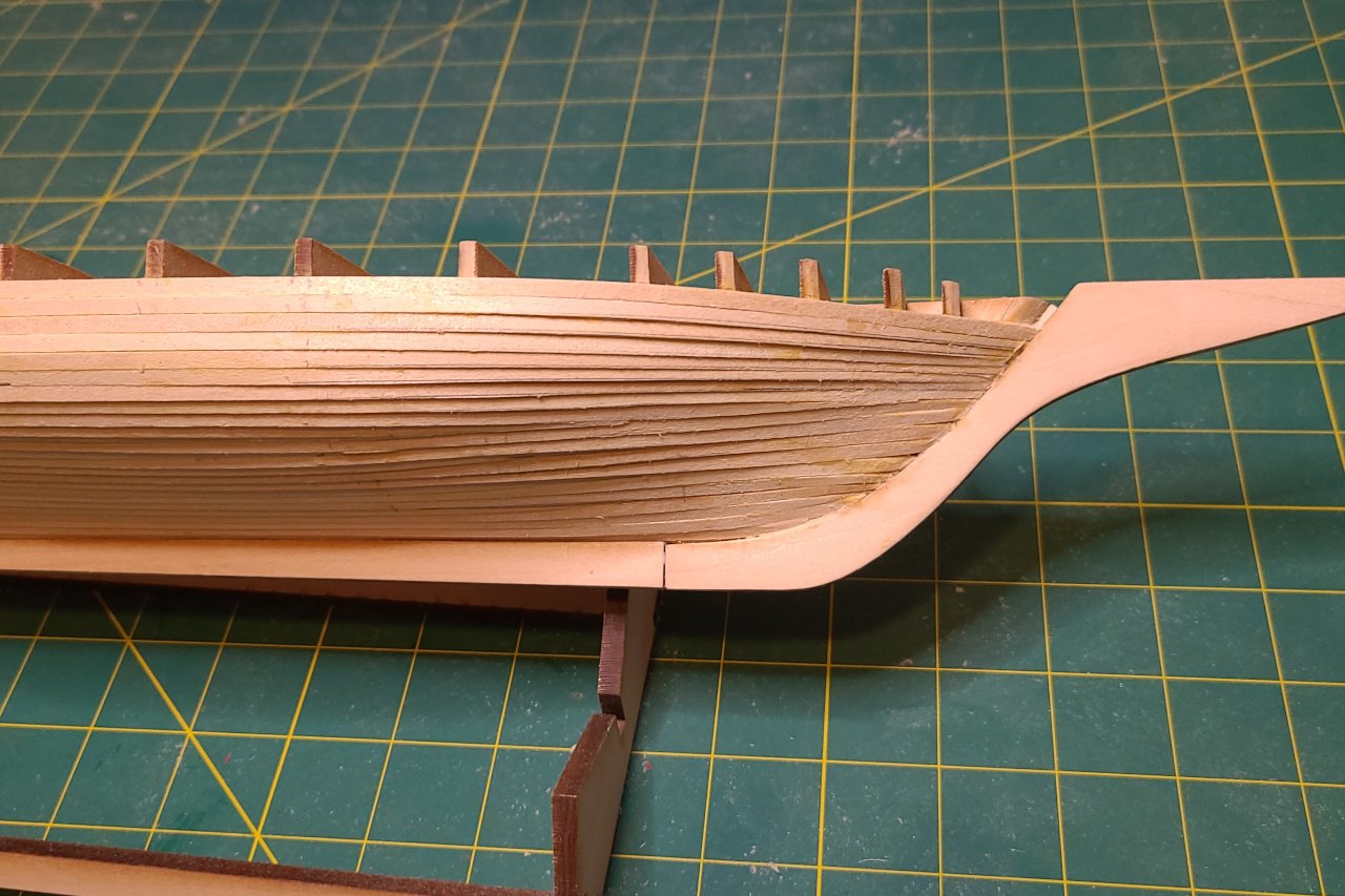
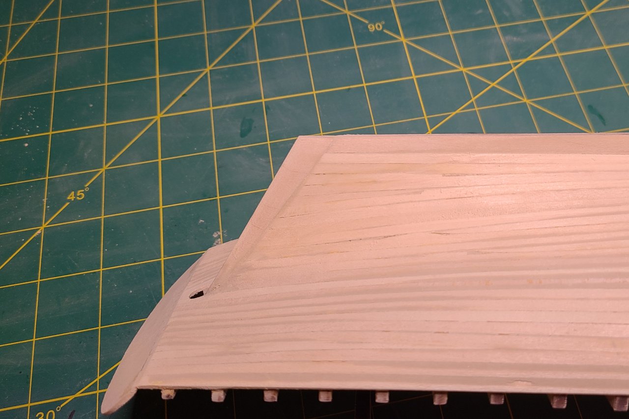
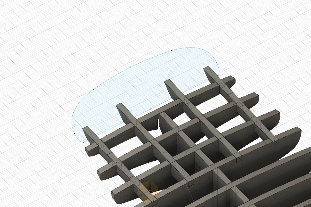
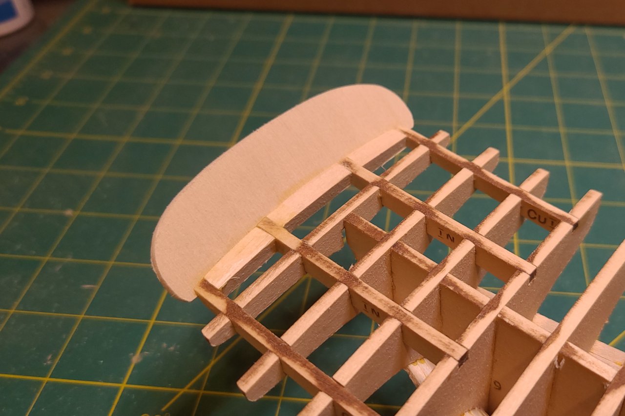
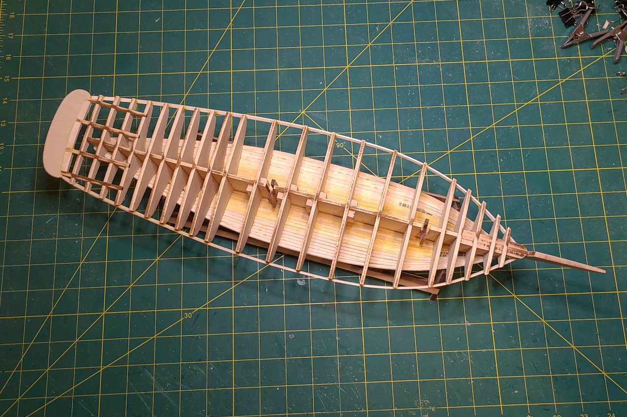
A small update. I built up the area at the bow. And also addressed the issues with the stern. Have a look at my last update to see what was wrong. I needed to add a thin strip along the edge that would add enough material so that the entirety of the stern would be smoothly rounded. Since I already had the shape of the stern in Fusion, I created and 3D printed a piece to use to form the strip. A 1/16" x 1/16" strip was soaked until it became flexible, then it was bend around the 3D printed piece and allowed to dry. After gluing the piece on, adding some filler, and sanding, the stern now has a nice shape.
-
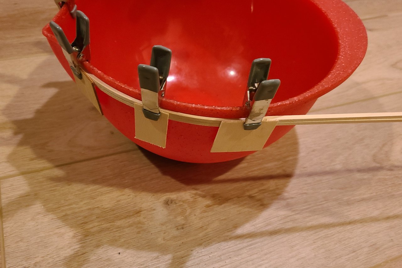
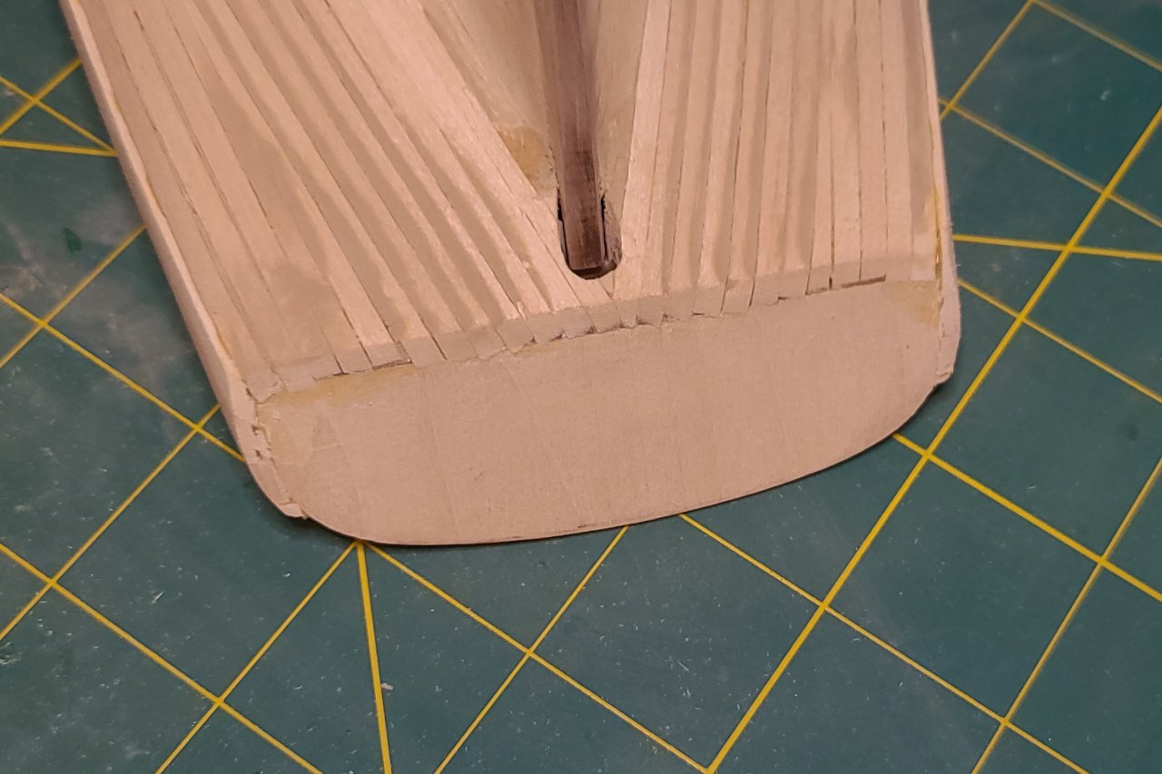
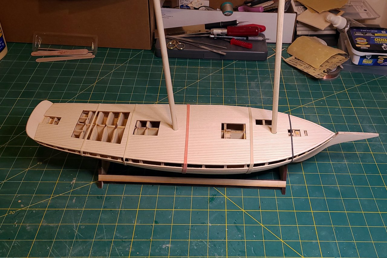
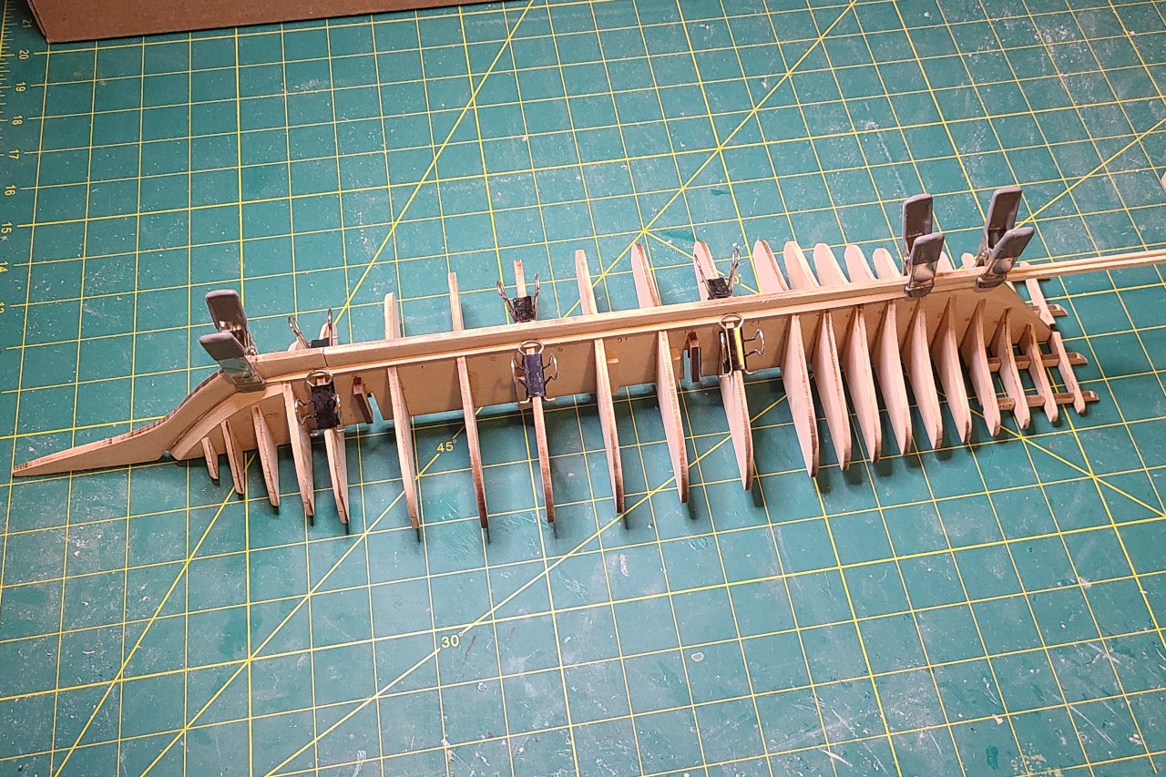
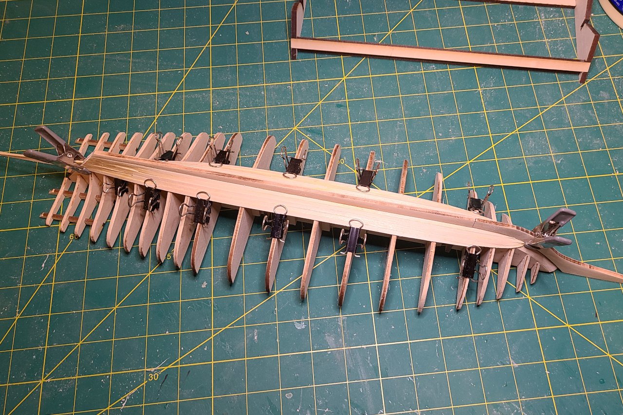
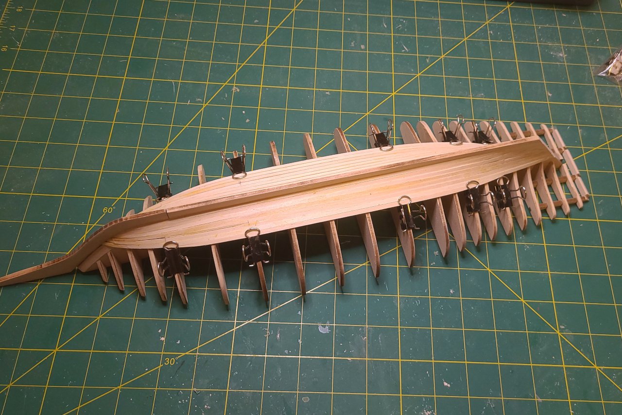
Now it's time to plank the hull above the bends line. The planking needs to be thicker, so I used 1/8" x 1/8" strips. They don't bend well on their own, so I soaked them in water and clipped them around a bowl to encourage the most extreme curve needed. Two planks added... And four planks... There is a bit of a gap between the planks aft. (And other imperfections not visible in these pictures.) These bits were added at the front that reinforce the hawse holes. (There is probably a name for them, but I'm not aware of it.) The stern has issues. The thick planking just added runs too high and will need to be reduced. And the whole stern needs to be more rounded. Also, I think the piece I fashioned is too short. After wood filler and hours of sanding, things are looking better. The stern is improved, but still needs work. I'm going to try to bend a thin strip to fit around the top of the stern. Somehow... I also stained the deck, then tried to sand it back to give it a weathered look. It's not too bad. The biggest issue is that, because the deck was laser scribed from a single wood sheet, there are some natural patterns in the wood that continue across planks. Next time: Adding some hull details and getting it ready to be painted.
-
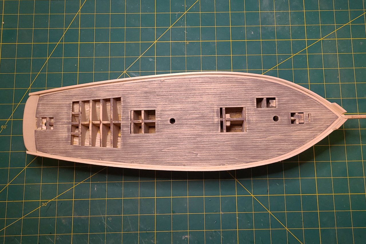
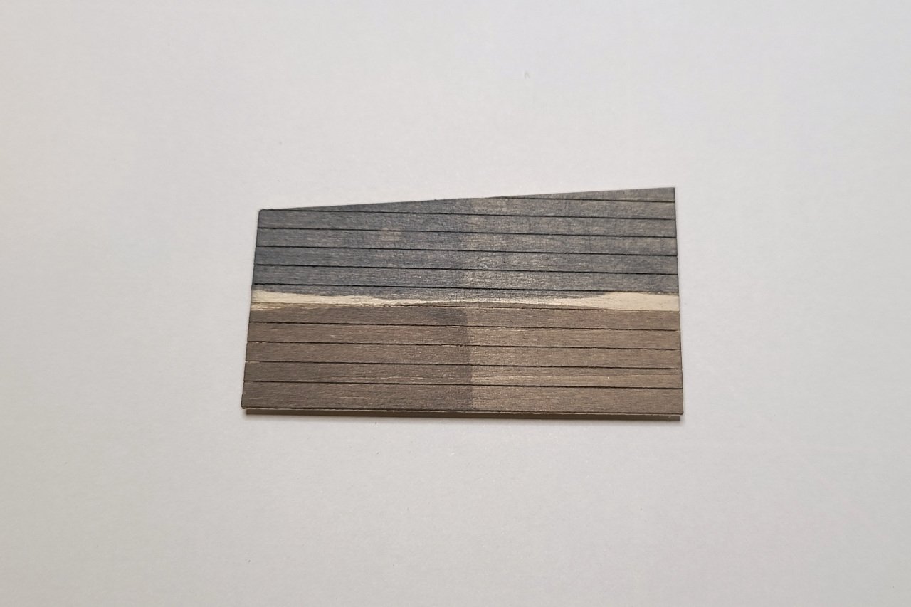
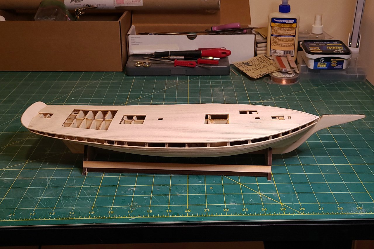
I wanted to get the deck in place next, as the sides of the deck would add more surface area to attach the bends planks. Rather than planking the deck, I chose to laser cut a scribed deck. First I had to determine the pattern for the planks. Looking through pictures of schooners of the same location and era, I found that straight planks were as likely as planks that follow the curvature of the bulwarks. I did not find any examples of nibbing. I decided to go with the simple option of straight planks. The design was laid out in Fusion, including the waterways and cut outs for the various deck features. And it was taken to the laser cutter. (This was the second version. I cut one originally then discovered a flaw in it later.) The deck was aligned with the hull by inserting dowels into the mast holes. Then rubber bands held the deck in place while the glue dried. And the deck is in place. I want the deck planks to have a weathered look. I picked up two stains that looked likely to work. The top is "weathered gray" and the bottom is "classic gray". A solid coat is at left and at right was the result after wiping the stain immediately after application. None of these is exactly what I'm going for, though the result at the bottom right is closest.
-
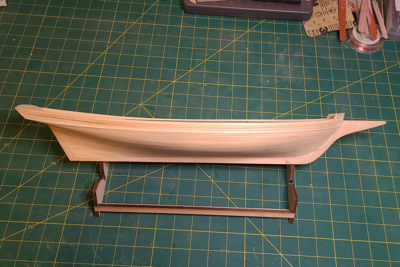
Planking of the hull was finally completed. The planking was quite clinkered in spots, especially here at the bow. Fortunately, wood filler exists. After a generous amount of wood filler and lots of sanding, the hull is pretty smooth. The stern post was glued on and a few gaps were filled in.
-
I listed pungies built by Joseph W Brooks, but he built other vessels too. The schooner Mattie F. Dean was built by him, but wasn't a pungy. There is a painting of the Mattie F. Dean on the Mariner's Museum website. Can you see what non-pungy features it has? I'll have to think about this. There are some flaws in my laser cut patterns that I've had to work around. I'm a little hesitant to give them out.
-
Planking of the hull continues. In Fusion, I designed the stern piece. It was not worth the trouble to go get it laser cut. I just printed out the pattern and then cut it from 1/16" sheet. The strake immediately below the "bends" was planked. If you look back at my laser cut patterns, you'll see where the location of this was marked on the bulkheads. Getting this strake in exactly the right position is important, so that the bends (which will be thicker) will run correctly. Now I'm planking the remaining space to complete the lower hull. I have family visiting this week, so work will be on hold for a little while.

-
Thanks, Jerry. I have updated the post to use the correct term.
-
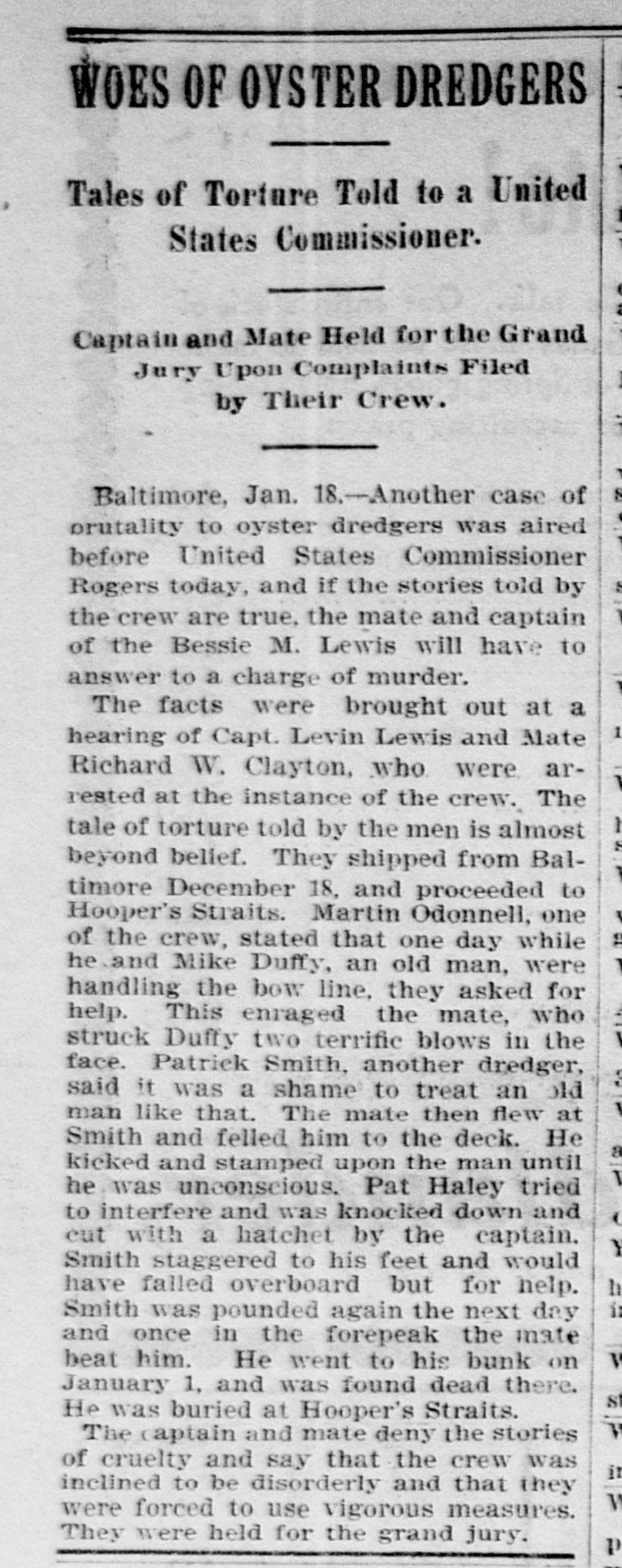
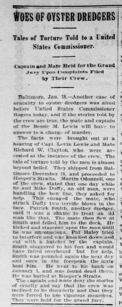
I couldn't find an account of what happened to Lewis after. However, I did find that Lewis was arrested for the incident described below. (Washington Times, 19 January 1898). His sentence was 2 years in jail and a $100 fine. Lewis died in 1902 at age 41.
-
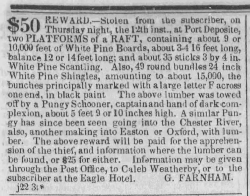
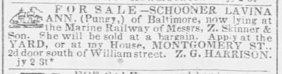
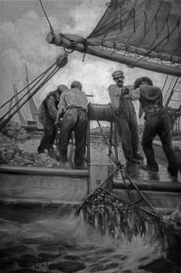
Historical Interlude 1 - What is a pungy? The pungy was a schooner unique to the Chesapeake Bay, a direct descendant of Bay pilot schooners and 1812 blockade runners and privateers. [1] The pungy type originated in the 1840’s. [2] The first mention I could find of “pungy” referring to the Bay schooner is the clipping below, from the Baltimore Sun 22 June 1840. The advertisement below shows that the term “pungy” was in use in the 1840’s. Below: Advertisement for sale of the pungy Lavina Ann, Baltimore Sun 5 July 1847 No one knows for certain the origin of the name “pungy”, but some speculate that it comes from Pungoteague or Machipungo, two towns on the lower Eastern Shore of VA. [3] Below: Builder's half hull model of a pungy, circa 1855. Image source: Chesapeake Bay Maritime Museum, retrieved from https://collections.cbmm.org/mDetail.aspx?rID=2004.0057.0001.00&db=objects&dir=CBMM A number of characteristics distinguished pungies from other Bay schooners. [4] Pungy James A. Whiting (built 1871) painted by Louis Feuchter in 1947 Image source: The Mariner’s Museum, retrieved from https://catalogs.marinersmuseum.org/object/CL12482 A - Flush deck, with only deckhouses and hatches protruding above it B - No bulwarks, only a low log rail, to ease loading & unloading; open quarter rail aft C - Clubbed jib & foresail boom (after 1850) D - Raking stem and sternpost E - Stout spike bowsprit with minimal or no steeve, no jibboom F - Topsail, if present, is single gaff topsail on the main G - Topmast bowed forward Based on the builder's model of the pungy Ida, built in 1873, John G. Earle listed these characteristics of a pungy hull: [5] 1. Full convex bow; clean slightly hollow run, with displacement well forward 2. Sharply raking stem, curving into the keel to form a gently rounded forefoot 3. Sharply raking sternpost leading directly to transom (no counter) 4. Relatively sharp sections 5. Forward sections are all convex, and flare boldly, consistent with the strongly raking stem, to form a full, beautifully-rounded deck line forward 6. The after sections within six feet of the stern become nearly horizontal for the greater part of their lengths, fairing to the sternpost rabbet in a concave curve and on the outboard ends, rounding to the stern in a quick convex curve. High, flat after sections with shallow quarters, are typical of the pungy. During the warm part of the year, pungies would haul cargo, bringing produce, lumber, and grain from points around the Bay to larger cities, and returning with fertilizer and other goods. Pungies would also make runs to the West Indies to pick up tropical produce. Their speed minimized the spoilage during those trips. [6] During the winter, pungies fulfilled their primary role: dredging for oysters. The pungies’ rig was particularly adept at crossing back and forth across the oyster beds, dragging the dredge behind. This was difficult and dangerous work. Conditions were cold and wet, leading to pneumonia and frostbite. Wounds to the hands were common during the culling of oysters. And unexpected jerks and reverses of the dredge handles could cause all manner of injuries. [7] Below: "The Dredge Comes Up from the Deep like a Mining Cage of Steel" painting by Clifford W. Ashley 1908 (best known for the Ashley Book of Knots) Image source: The Mariner’s Museum, retrieved from https://catalogs.marinersmuseum.org/object/CL20648 Pungy captains sought out vulnerable men to do this work. European immigrants, who could not speak English, were popular targets, as were men recently released from jail. Below: 24 November 1896 article from Der Deutsche Correspondent, a Baltimore newspaper for German immigrants Translation: A brutal captain. On the basis of an arrest warrant from the Federal Commissioner, L. F. Lewis, captain of the oyster boat "Amanda F. Lewis," was arrested yesterday afternoon by Sergeant Buckless on board his ship and released on bail for an interrogation taking place today. Lewis is accused by Sieve McDonald, an oyster fisherman on board the "Amanda F. Lewis," of having treated him and the rest of the crew in an inhumane manner. There were a few pungy variants. One called a "beanie" had the rudder stock coming up behind the stern, rather than through a hole in the transom. A "she-pungy" was a pungy with a centerboard. The Genesta (built 1885) and Kessie C. Price (built 1888) were two examples. The pungy dominated the oystering trade until the end of the 19th century, when bugeyes and then skipjacks became the preferred craft for oyster dredging. Pungies acted as buyboats for oysters and continued to haul other cargo, but were quickly replaced by powered craft. 1: Footner, Geoffrey M. (1998). Tidewater Triumph. Mystic Seaport Museum Inc. pg. 253 2: Burgess, Robert H. (1975). Chesapeake sailing craft. Tidewater Publishers. pg 59 3: Snediker, Quentin and Jensen, Ann (1992). Chesapeake Bay Schooners. Tidewater Publishers. pg 48 4: Snediker and Jensen. Chesapeake Bay Schooners. pg 48-49 5: Footner. Tidewater Triumph. pg 224 6: Burgess. Chesapeake sailing craft. pg 59-60 7: Wyman W. (1884). Hardships of the Coasting Trade, and Particularly of the Chesapeake Bay Oystermen. Public health papers and reports, 10, 273–281.

-
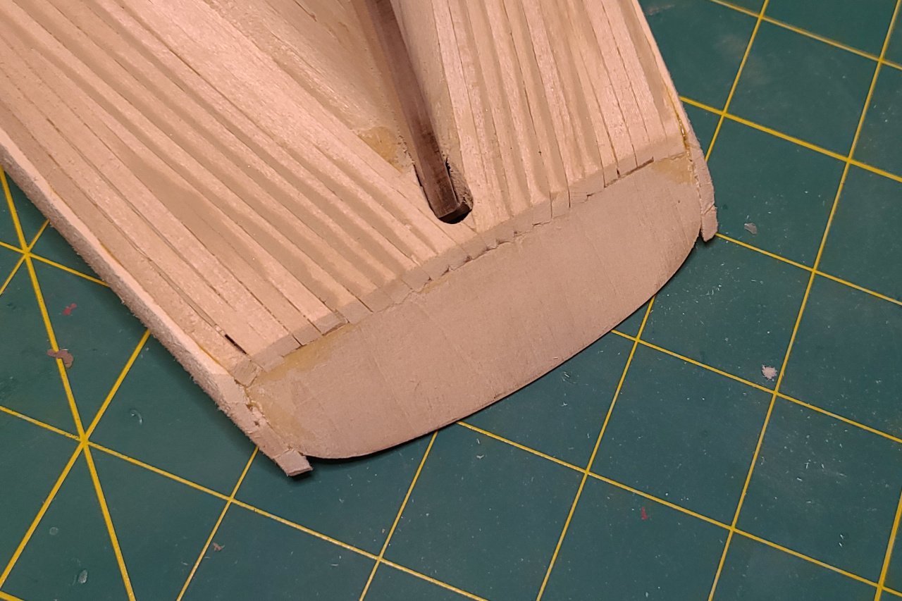
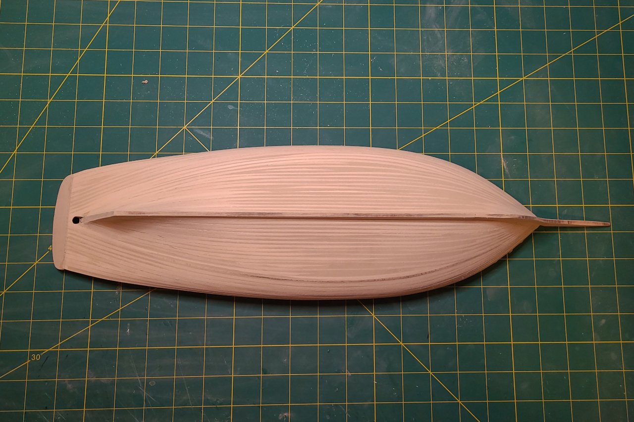
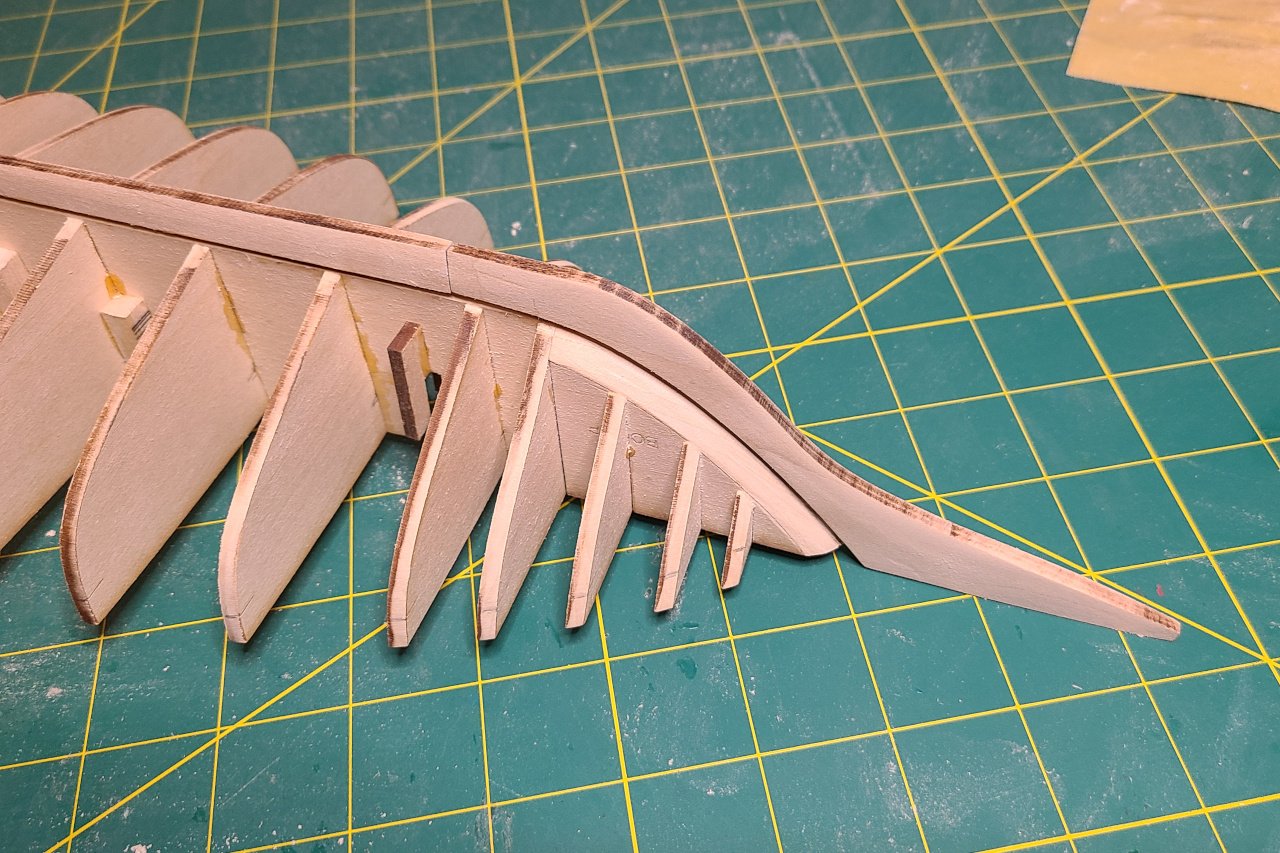
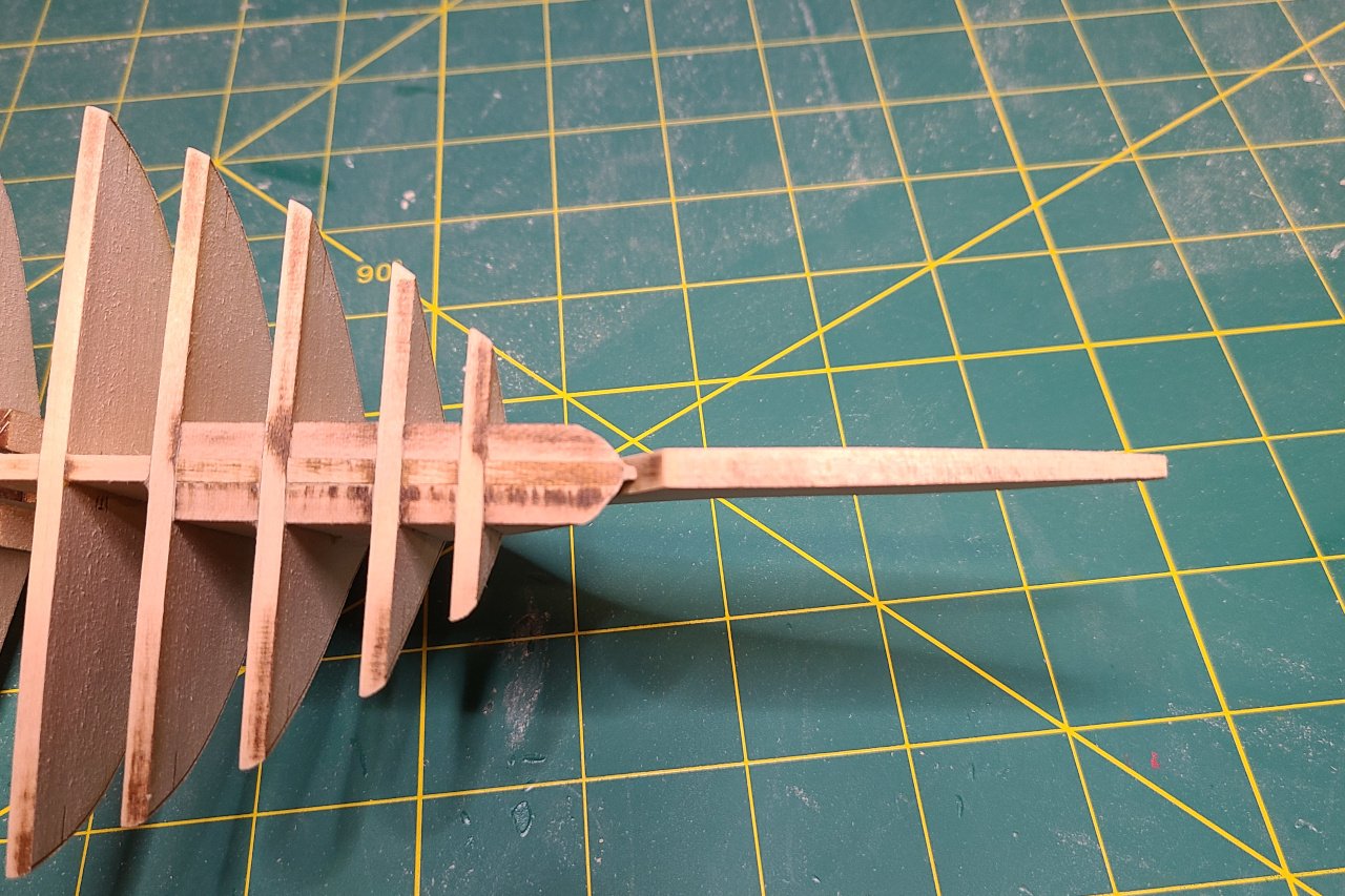
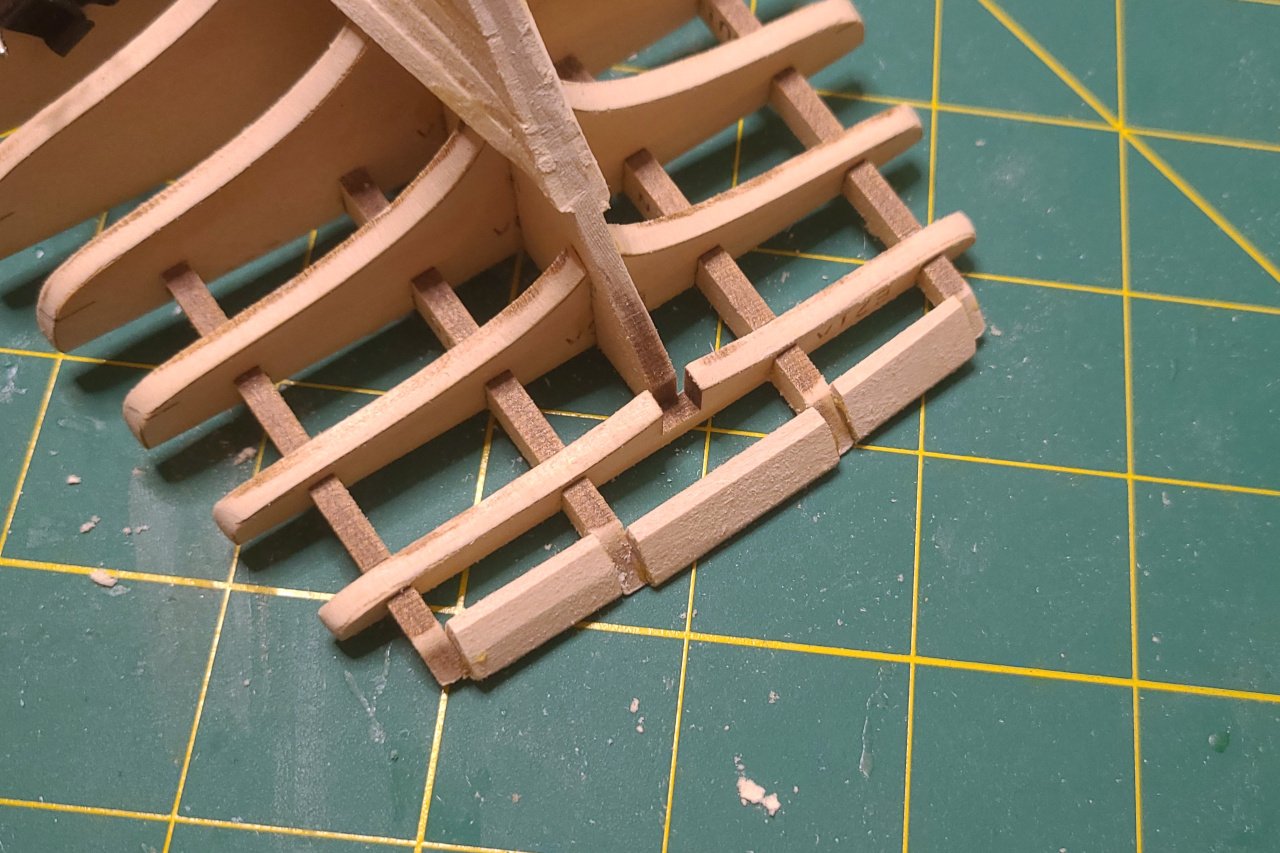
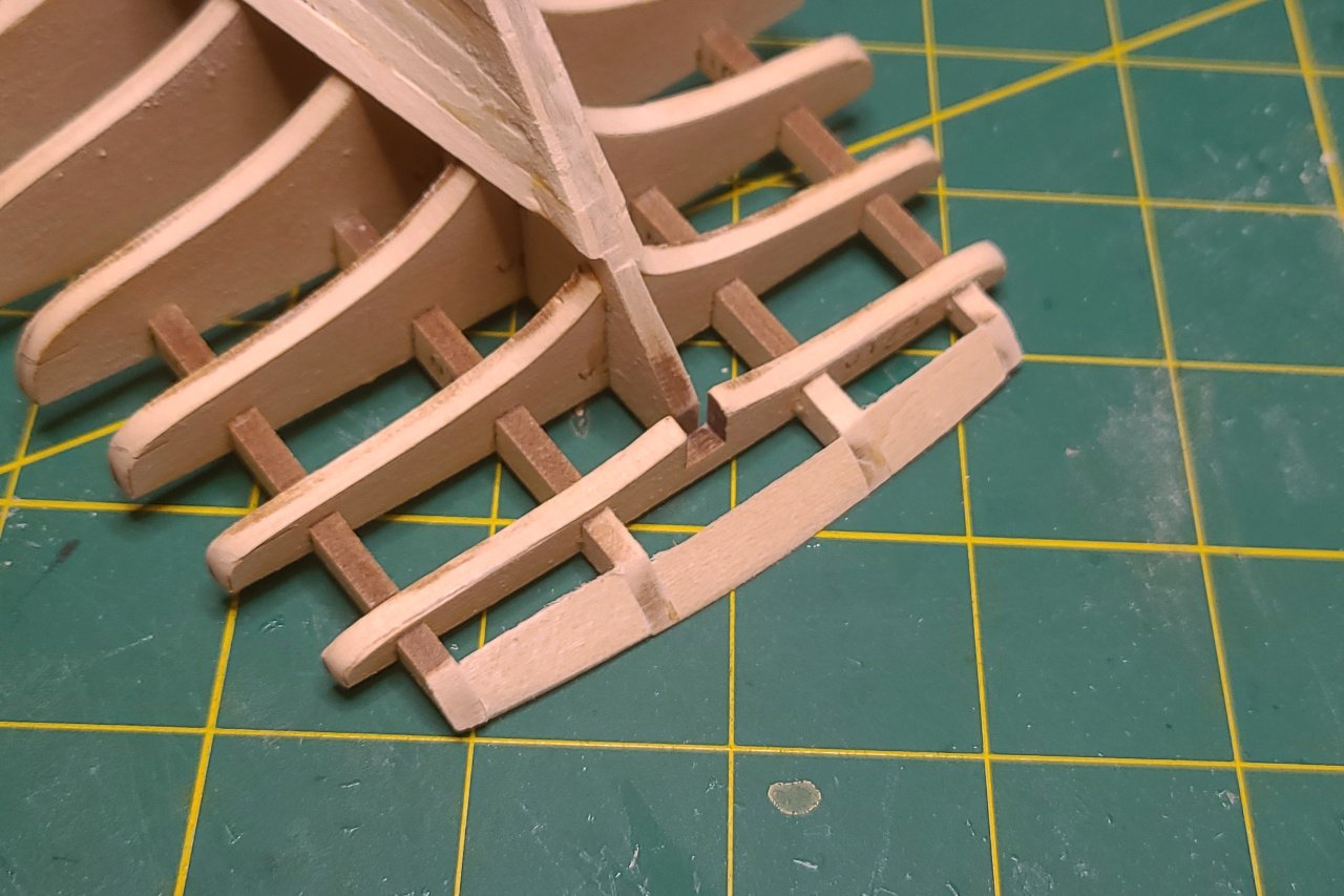
The stem and keel were tapered and then glued on to the thin strip. The ugly gap between keel and stem will need to be filled in later. The gap between the stem / keel and the thin strip on the false keel forms a channel that the planks will fit into. And the first planks are on. More planking... And more planking... It's not too bad, but there are gaps and imperfections. The plank ends at the bow are particularly ugly. Hopefully, filler and sanding will smooth it all out. I added some wood pieces here at the stern. And sanded them down. This will provide more surface area for the stern piece to be glued onto. Note to self: Need to make the stern piece. It needs to be in place before the upper hull can be planked.
-
SardonicMeow reacted to a post in a topic:
Amanda F Lewis 1884 by SardonicMeow - Scale 1:48 - Chesapeake Bay pungy
-
Hi, George. It's great that you have a connection to the Amanda F. Lewis. I presume your relative was Jeremiah Gibson (1846 - 1935)? He was her captain during the early 1900s. Washington Evening Star newspaper 4 August 1908: Washington Evening Star newspaper 28 August 1908:
-
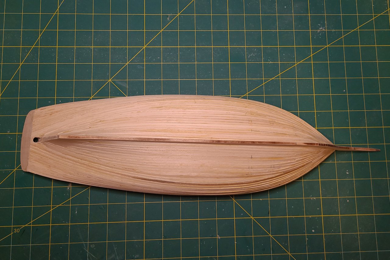
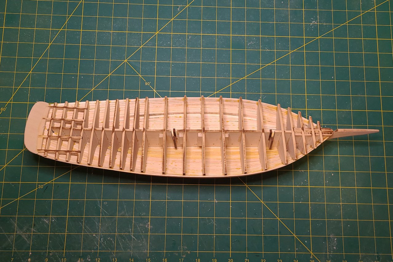
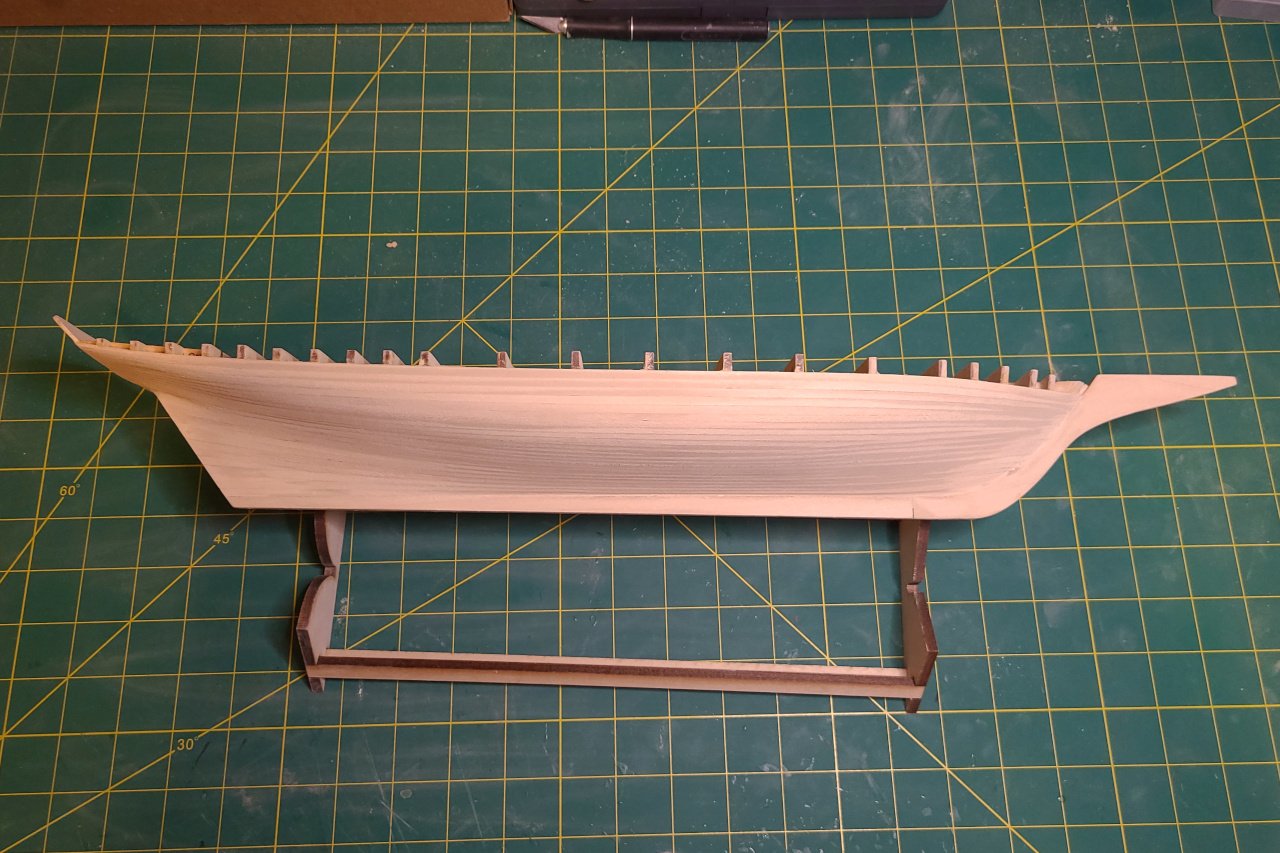
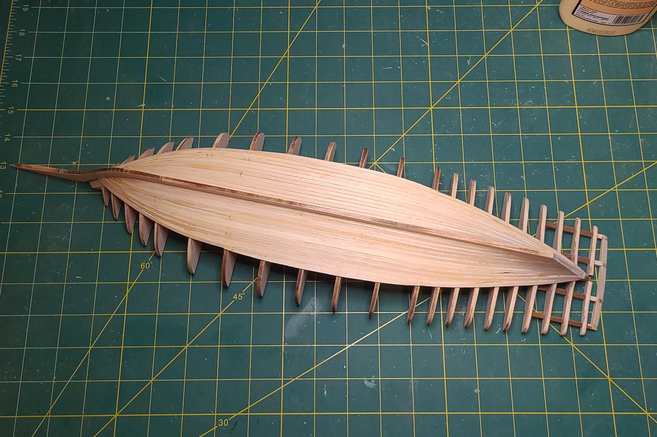
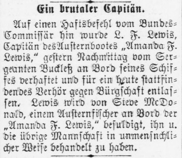
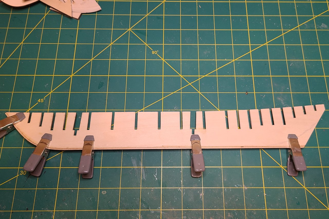
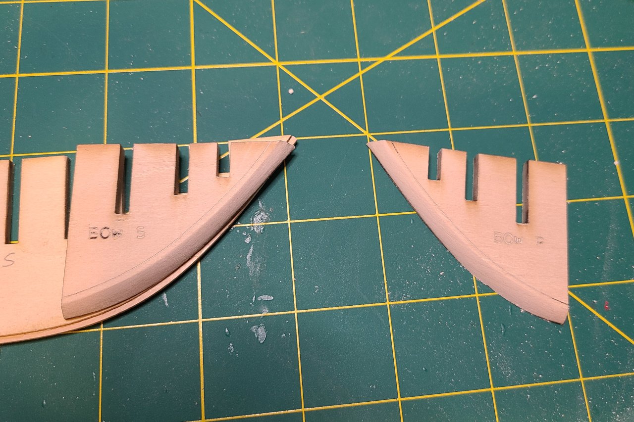
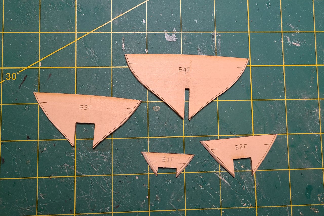
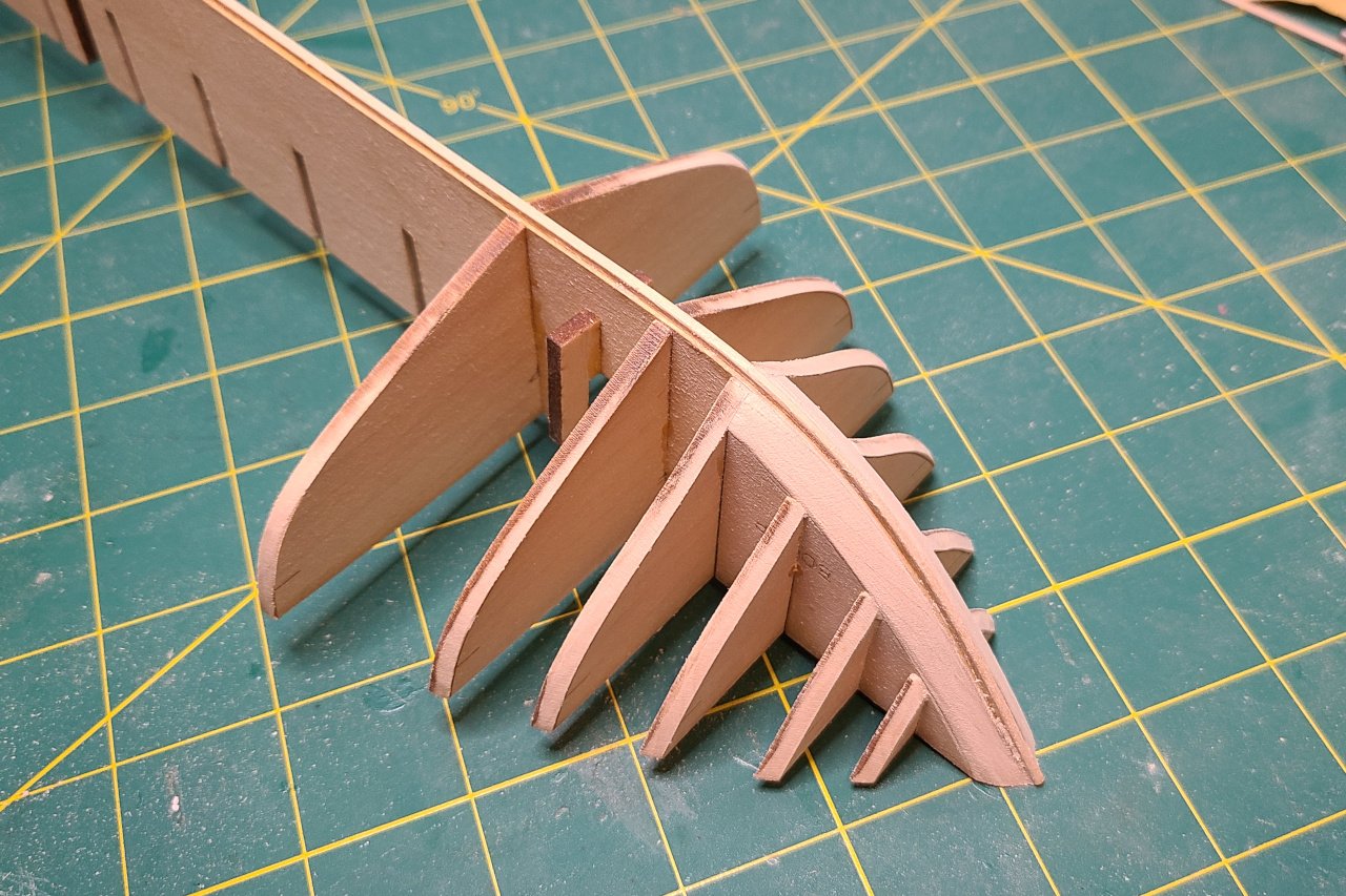
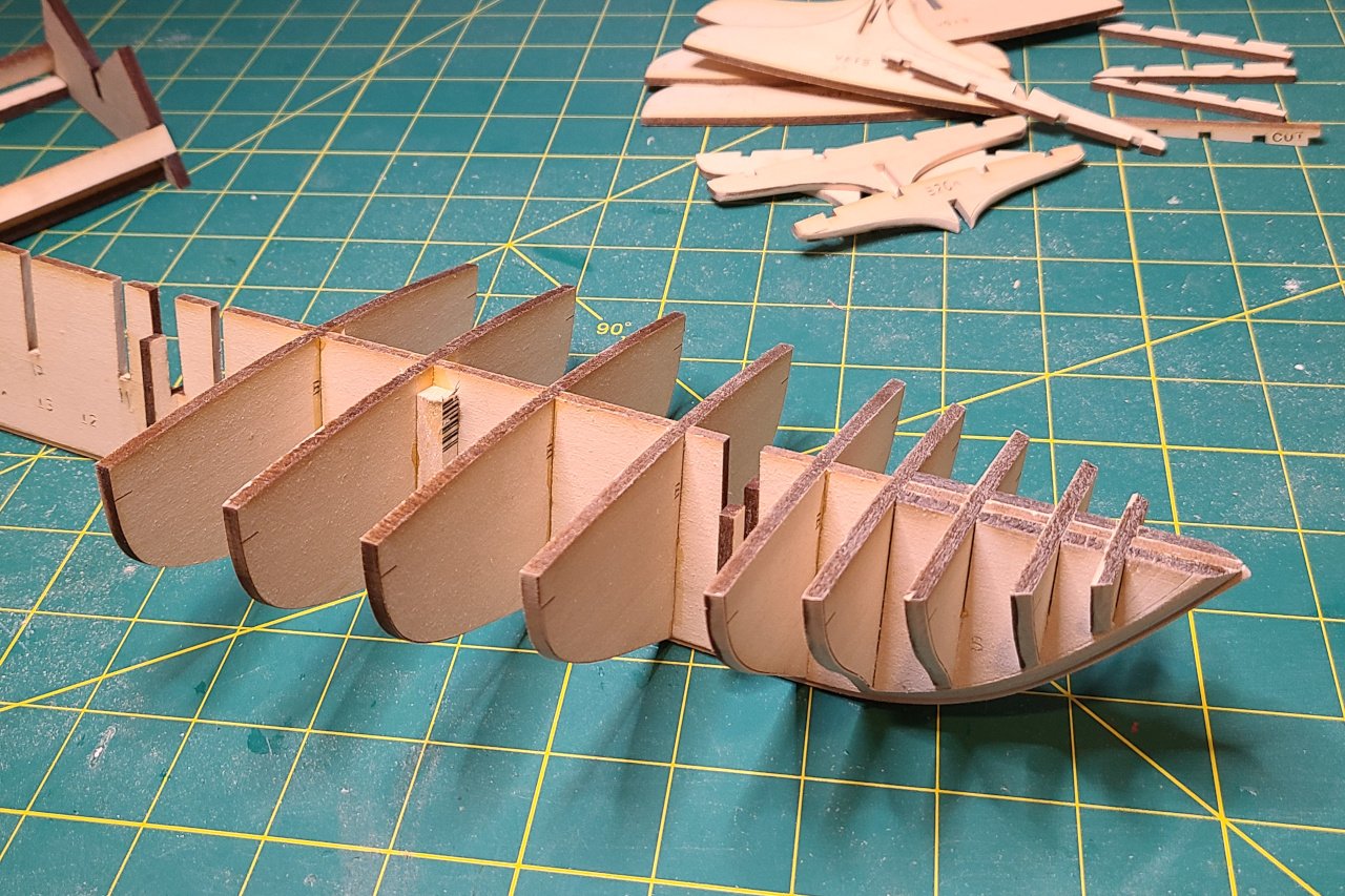
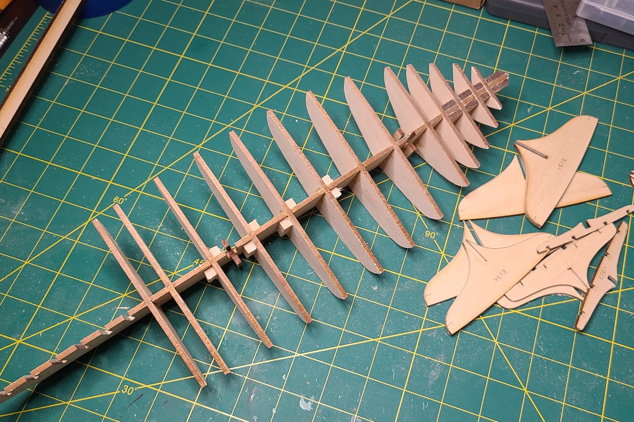
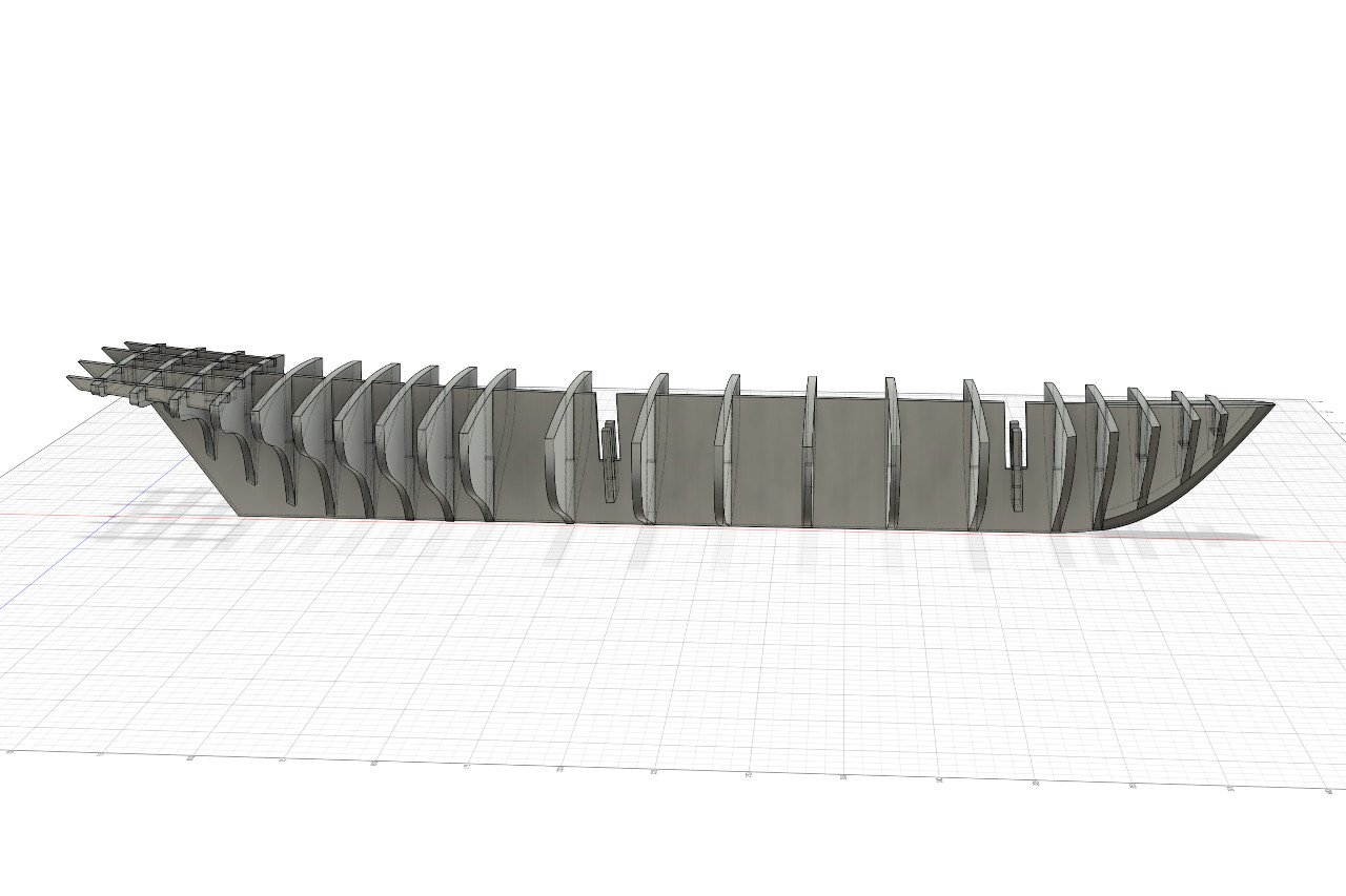
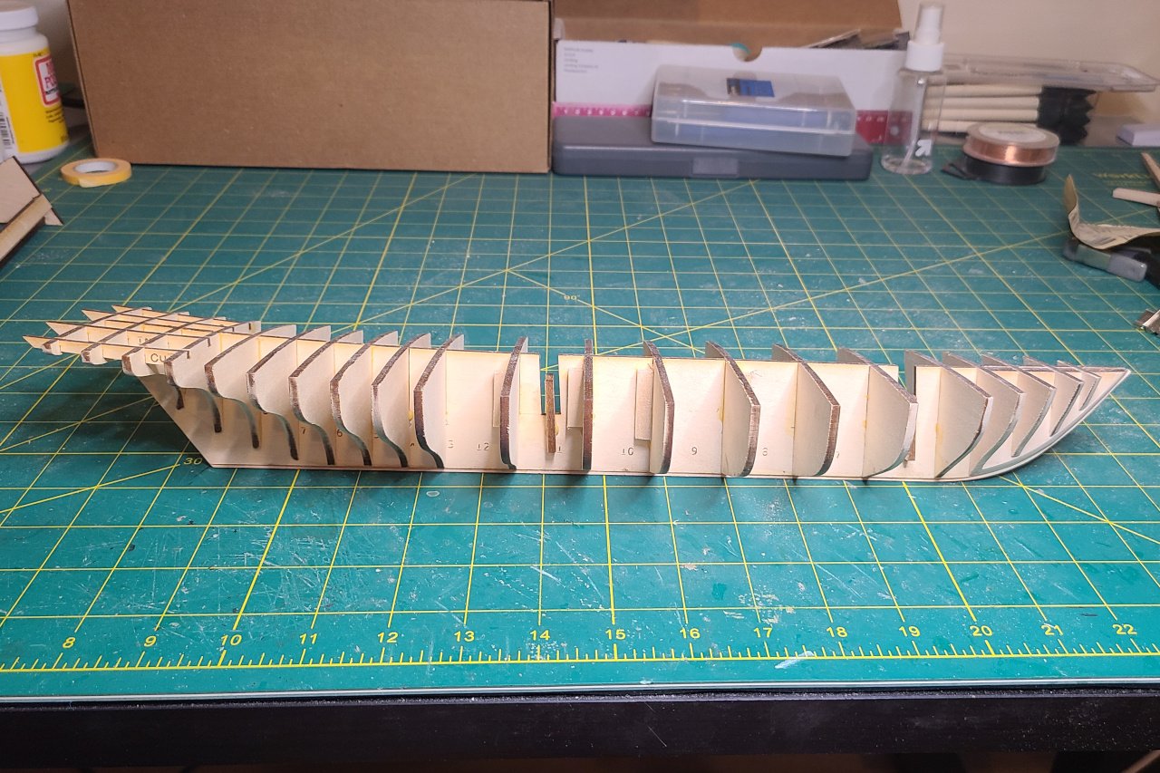
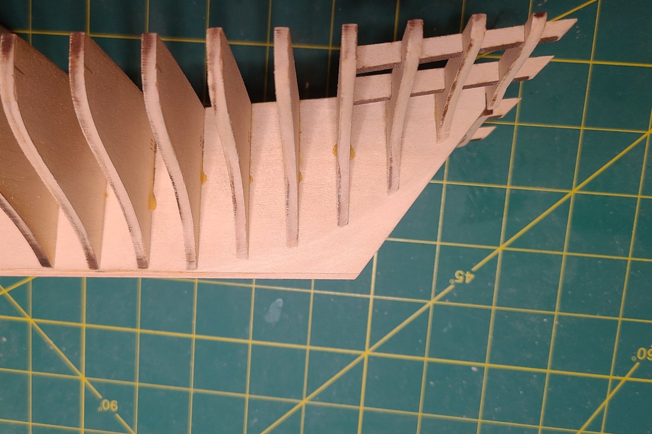
A thin 1/16" x 1/16" strip was glued to the bottom of the false keel to act as the rabbet. Pieces were partially faired using the engraved fairing lines. They will be sanded back further once glued in place. Here are the pieces at the bow after being sanded back. Adding more bulkheads... And more bulkheads... Everything is assembled. Here is the design versus reality: Lots of sanding the bulkheads aft to get a smooth surface. Also, the false keel was sanded thin below the bearding line. And it's just about ready to start planking.
-
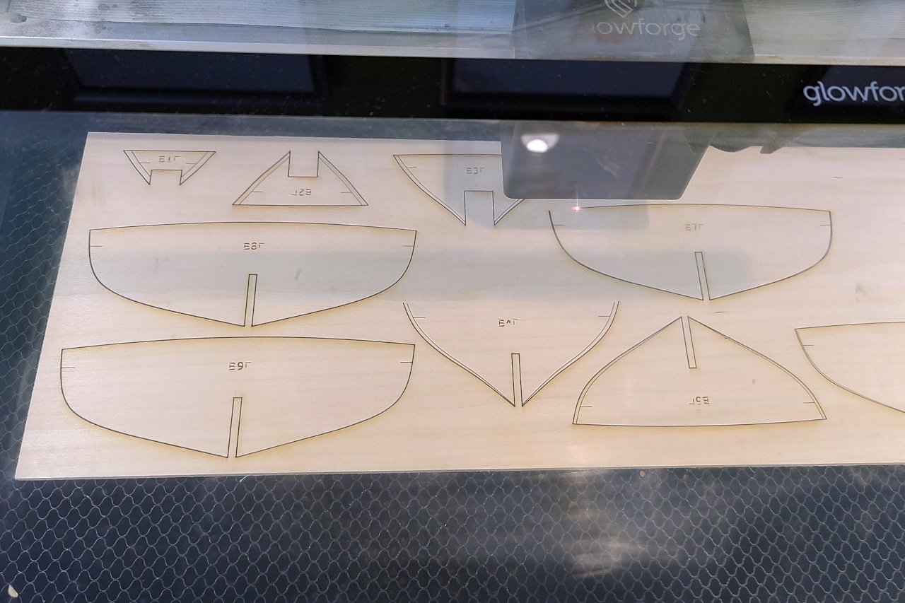
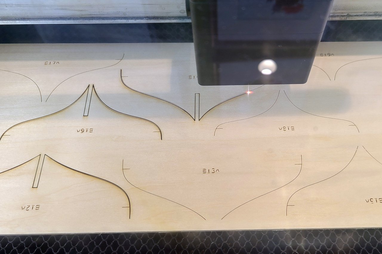
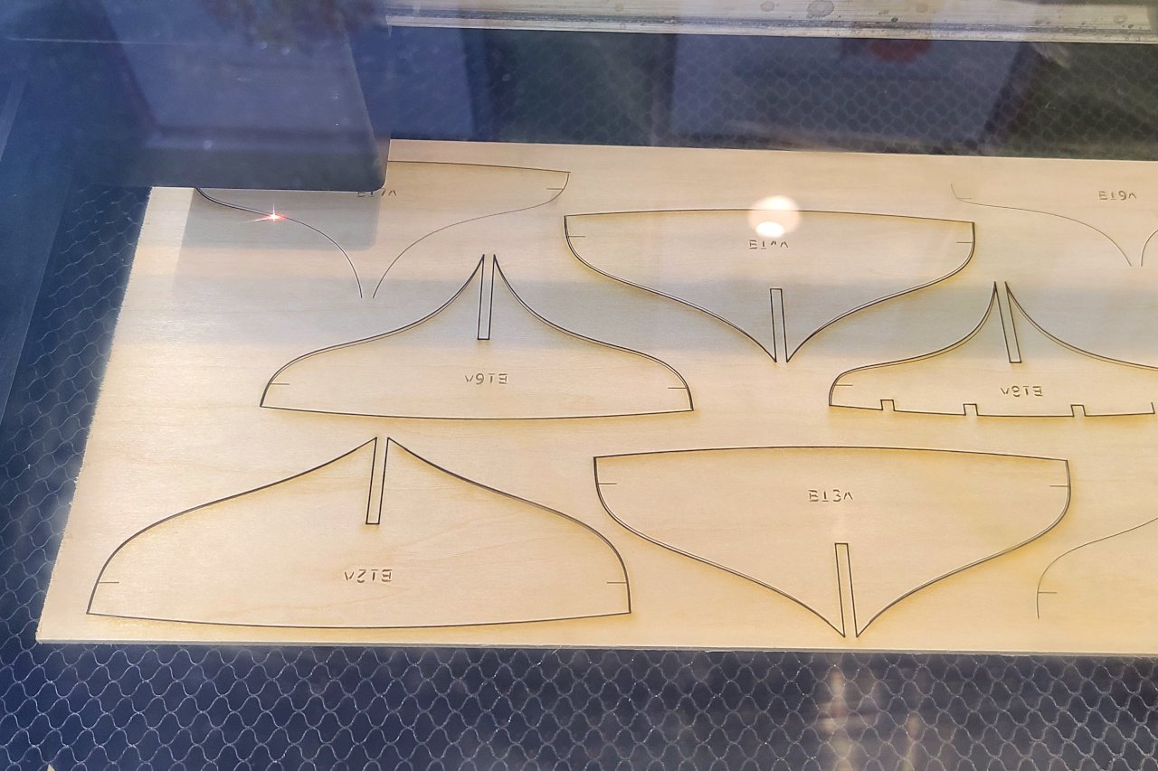
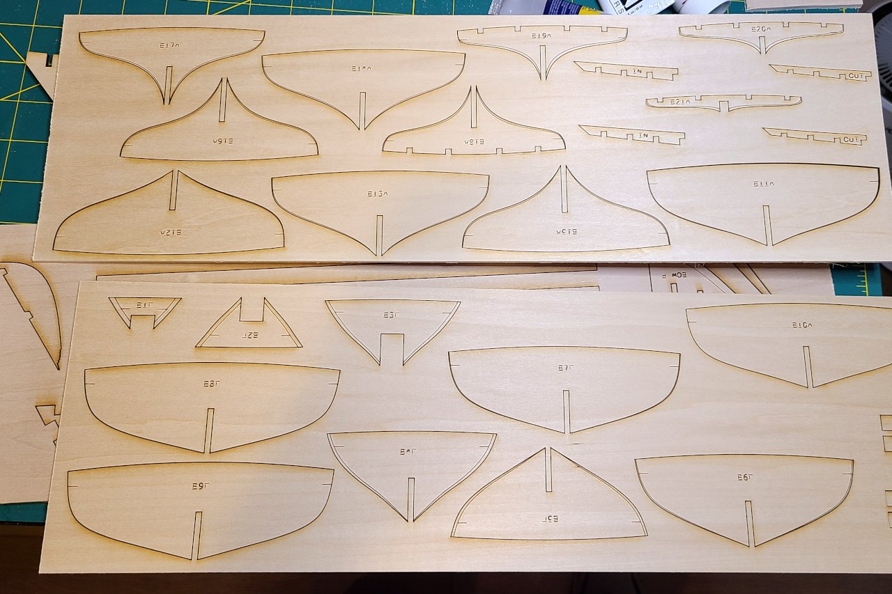
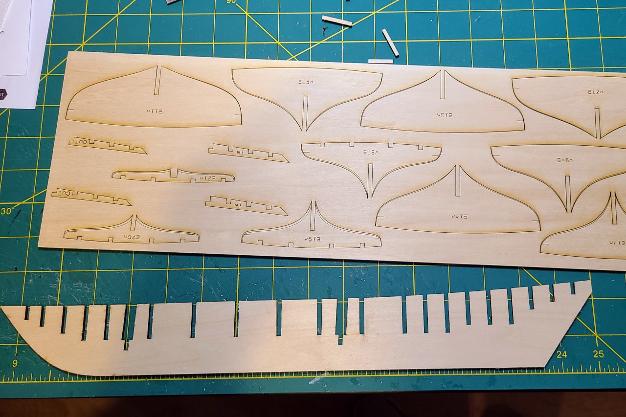
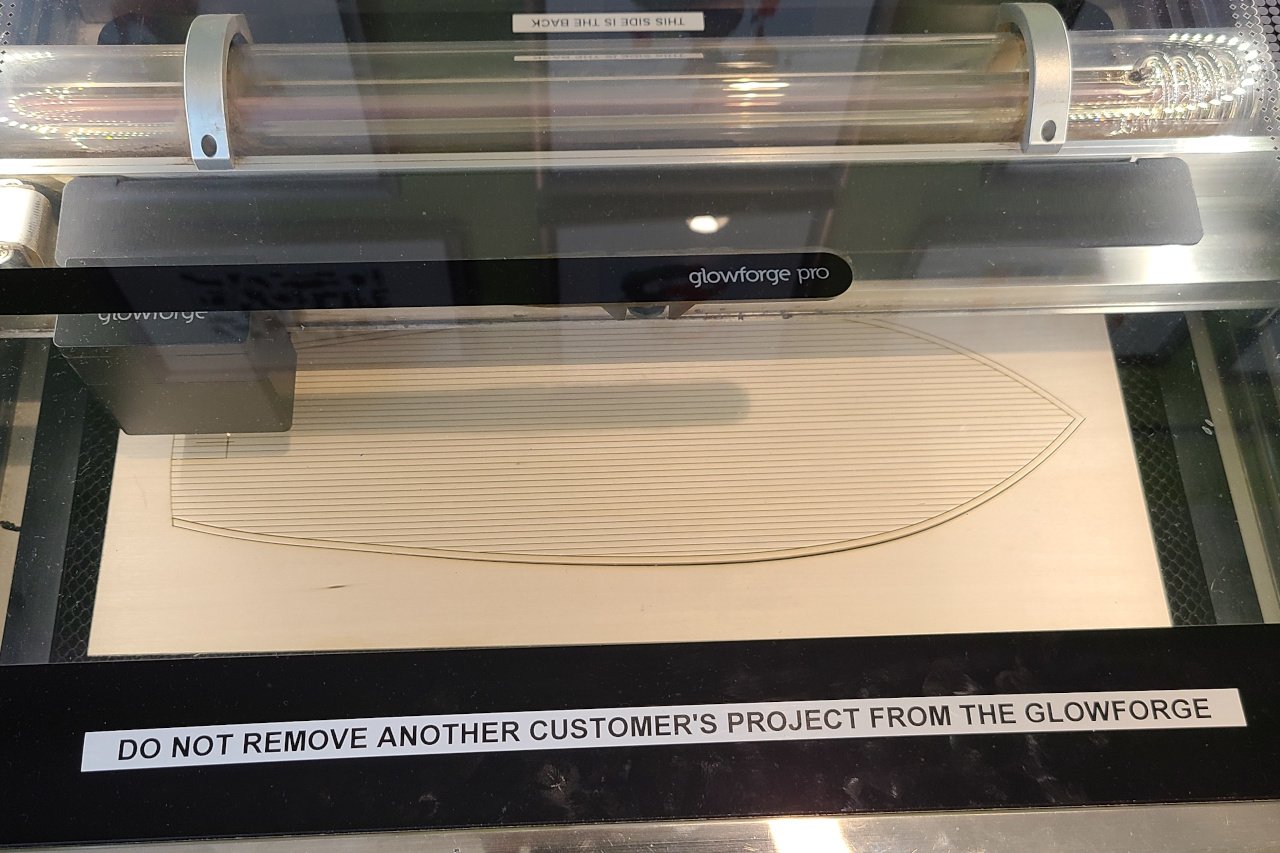
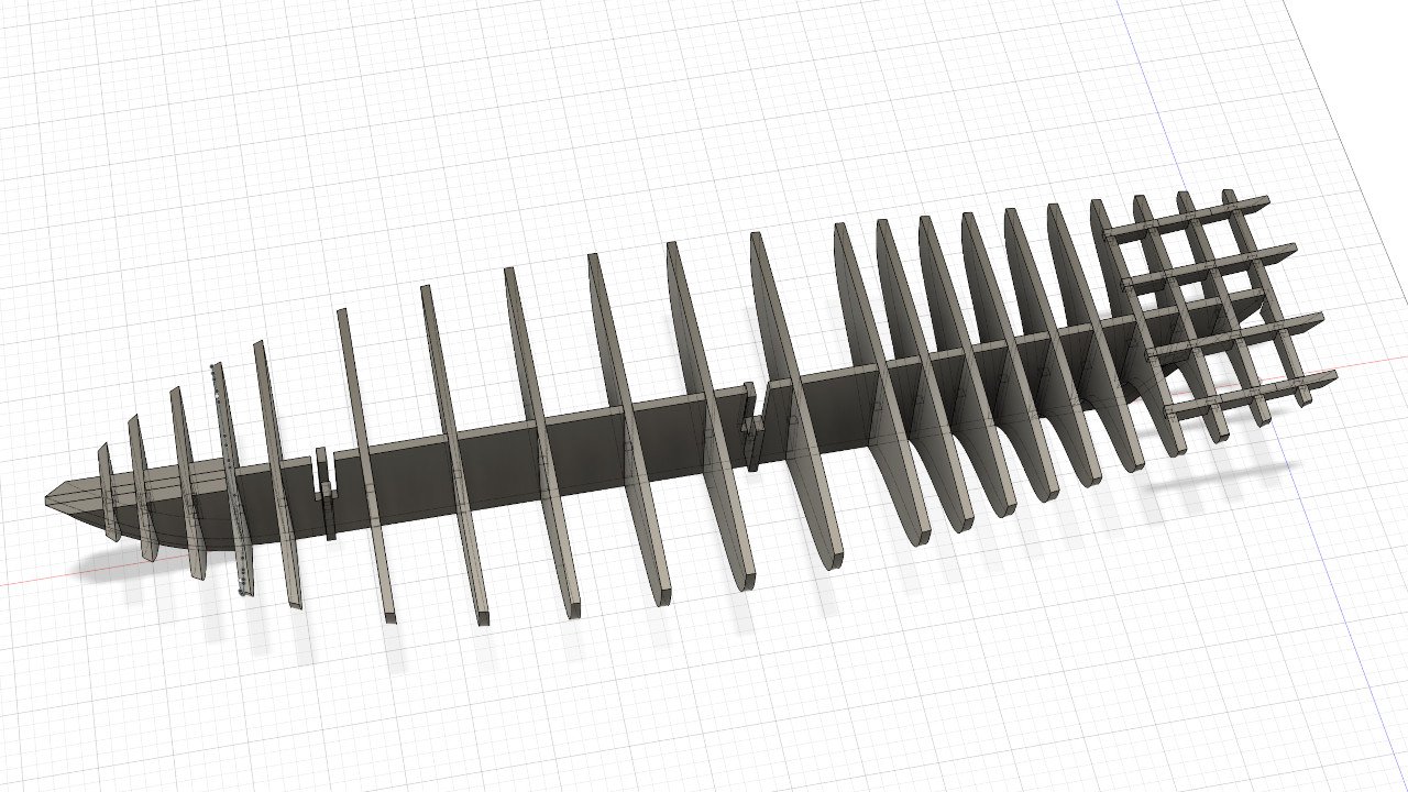
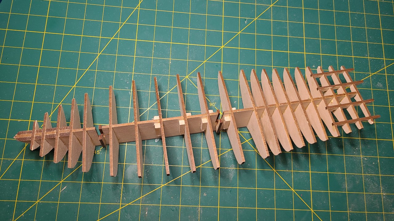
I am very fortunate to have a local library with a Glowforge available for public use. I visited and laser cut my pieces today. VRRRRMMMMM!!!!! ZAPPPPPPPP!!!! BBZZZZZZ!!!! (Insert your favorite laser cutting noises here.) And it's done. Time to put it all together. Some laser cutting notes: During some earlier testing, I estimated a .15mm kerf for the laser. I adjusted my patterns with that in mind, as I didn't want the pieces to be too loose when fitted together. However, I overshot and everything is too tight. I need to sand off a little bit around every notch. Ugh. I had some old laser cutting notes from my Sultana build that said that text should be converted to paths. I did that with all text, but some text has become unreadable. I think the Glowforge can handle text objects in SVG files, so I should have just let them be. Oh well.