HOLIDAY DONATION DRIVE - SUPPORT MSW - DO YOUR PART TO KEEP THIS GREAT FORUM GOING! (Only 13 donations so far - C'mon guys!)
×


SardonicMeow
-
Posts
333 -
Joined
-
Last visited
Content Type
Profiles
Forums
Gallery
Events
Everything posted by SardonicMeow
-
 Almost there... And done. Hopefully, filler and sanding will take care of most of the imperfections.

- 222 replies
-
- 3
-

-
- sultana
- model shipways
- (and 1 more)
-
Hi, Point and welcome to Model Ship World. While I'm still a modeling novice, I think you'll find my Sultana build (still in progress) to be of interest to you. It incorporates 3D modeling, laser cutting, and a little 3D printing (with more planned for later).
-
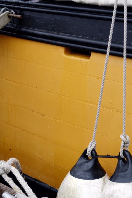
Yes, that's the look I'm hoping for. Something like in the picture below.
- 222 replies
-
- 1
-
-
- sultana
- model shipways
- (and 1 more)
-
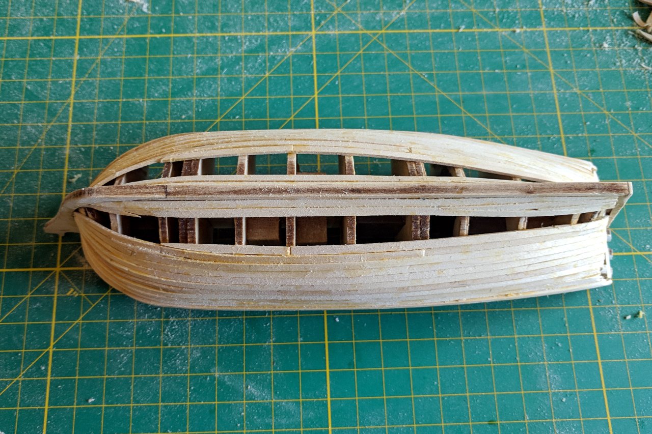
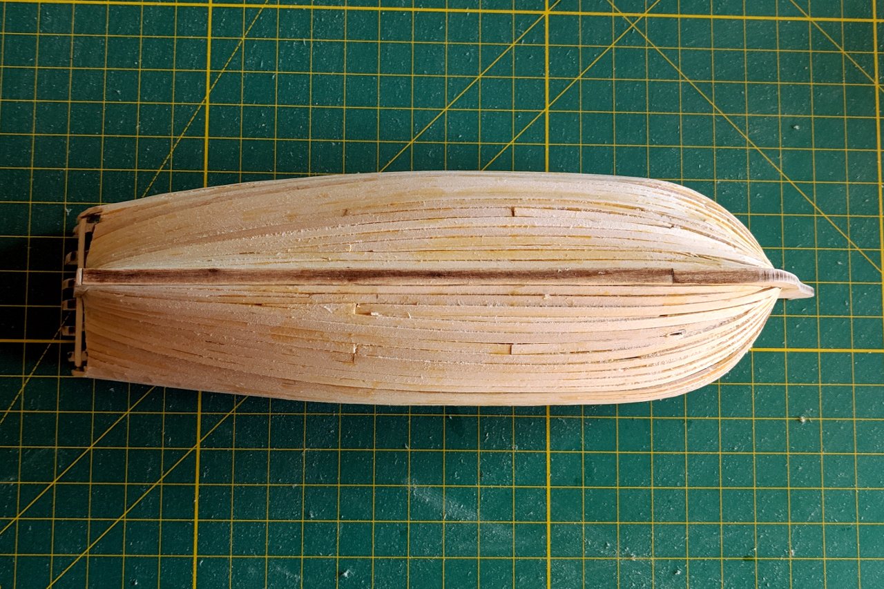
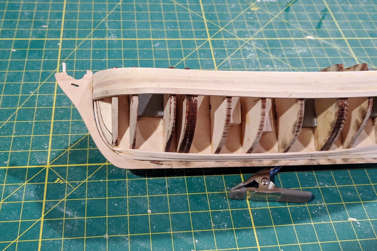
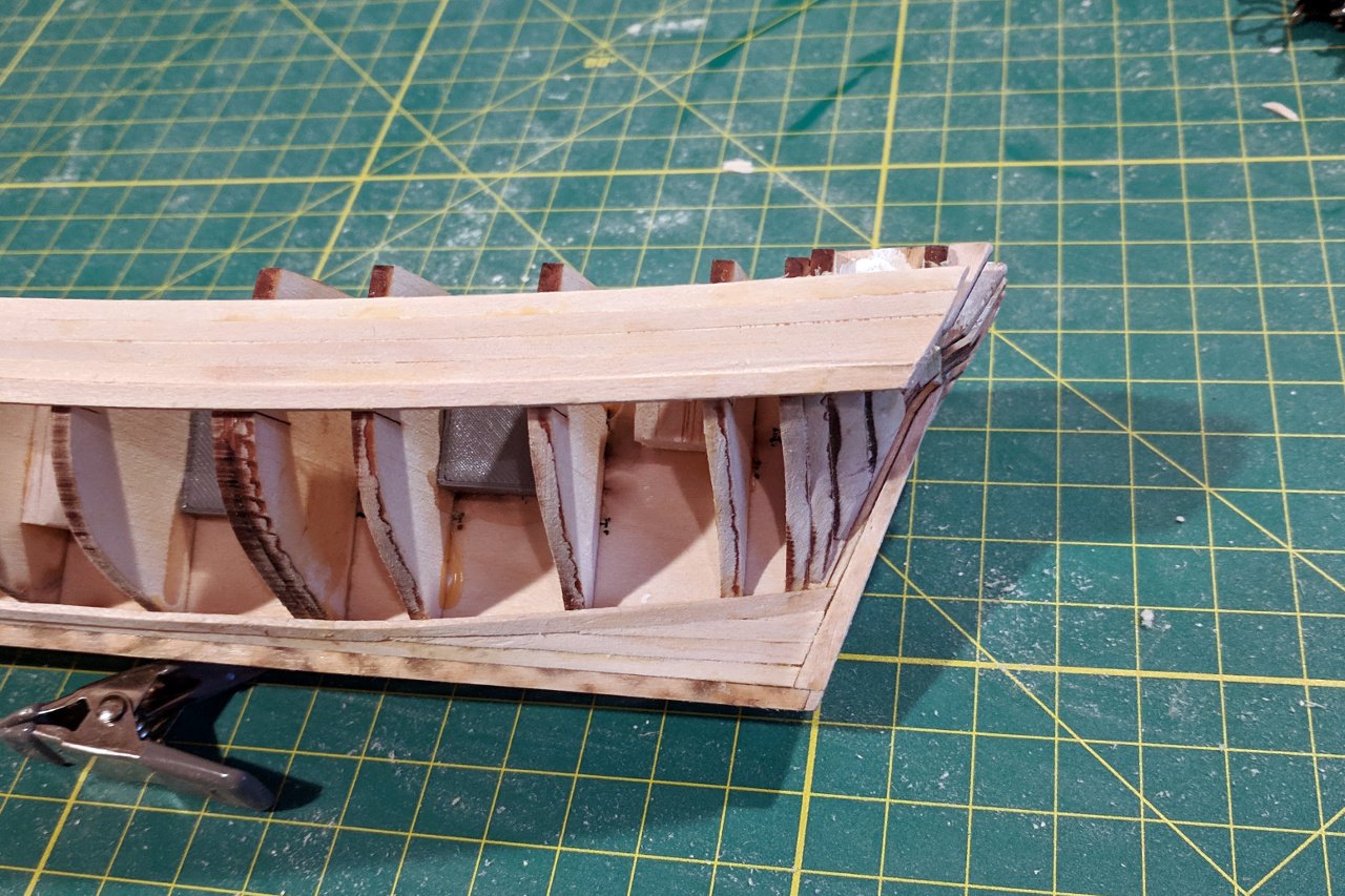
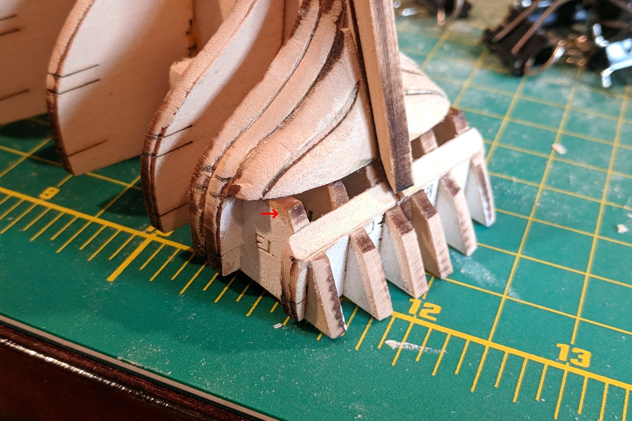
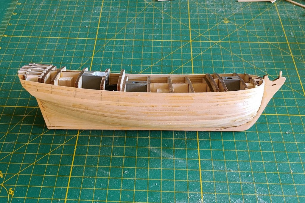
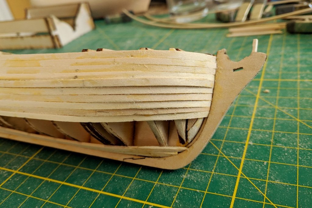
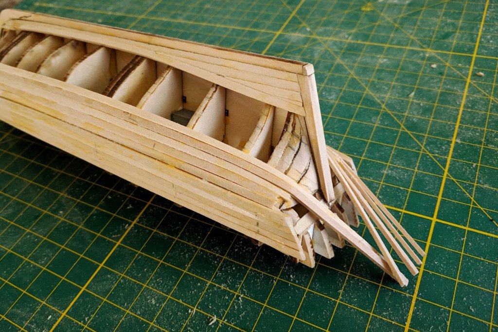
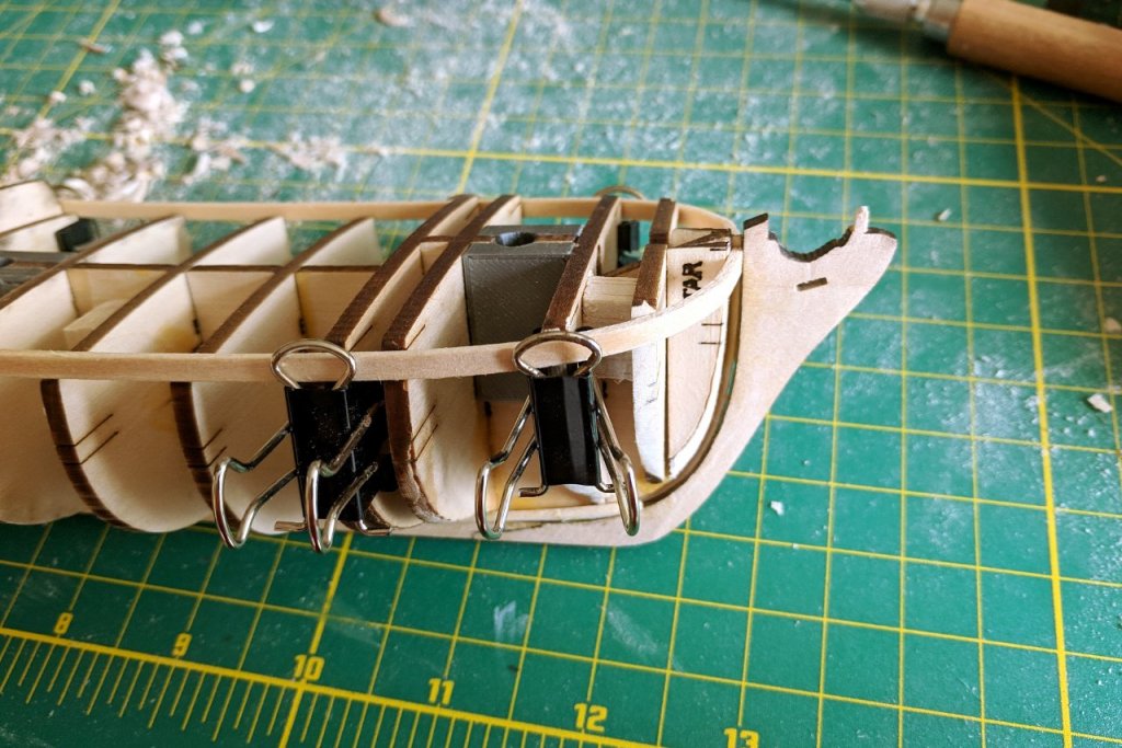
And more planking... This is only my second time planking a hull, and it shows. At the bow, things are getting a bit clinkered. I think it will be ok after gap filling and sanding, especially since I plan to paint the hull. The 1/8" x 1/16" strips I'm using are so thin already that not much spiling is possible. Here's the ugly part, the stern. Some of the planks broke while I was clamping them in place. The others I haven't cut down because I'm uncertain about where to end them. Also, it's a little hard to see here, but the wale strake should have been twisted much more back here. I think I may end up sanding down the wale strake completely then glue a 1/8" x 1/16" strip on top.
- 222 replies
-
- 3
-
-
- sultana
- model shipways
- (and 1 more)
-
Neat. I know intellectually that such a thing should be mathematically possible, but it still seems like black magic. With a table of offsets, you could get a nice set of curves built in no time.
-
Are you saying that you took the coordinates of points along the curve and plugged them into an algorithm, and the output was the coordinates of each of the control points for a spline that fits the curve?
-
I ran out of the lighter line very close to the end. I don't think I made any big mistakes that wasted it. There was definitely plenty of the darker line.
- 68 replies
-
- 2
-
-
- virginia 1819
- artesania latina
- (and 1 more)
-
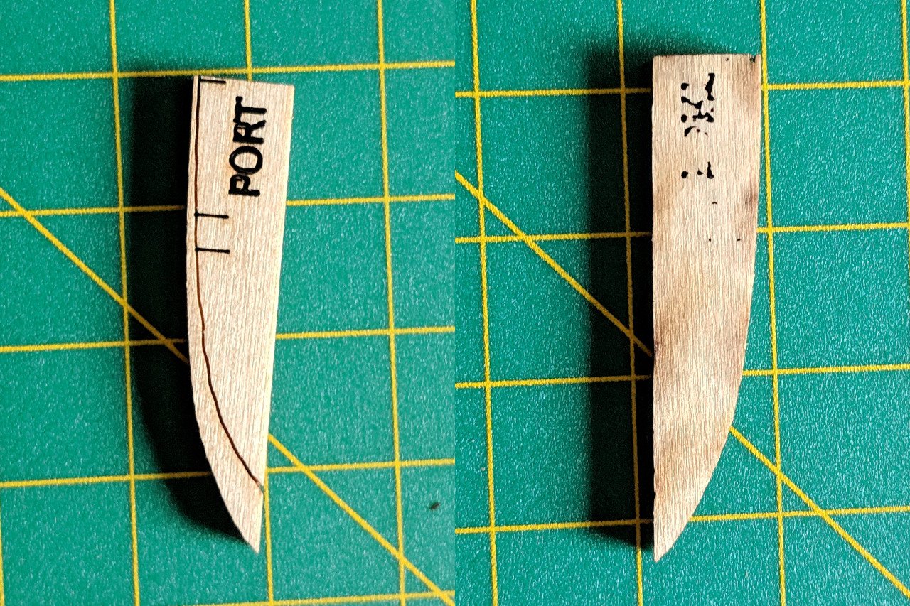
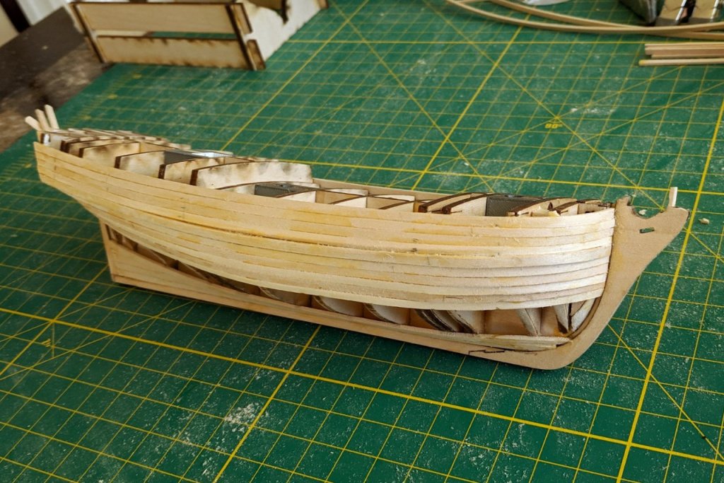
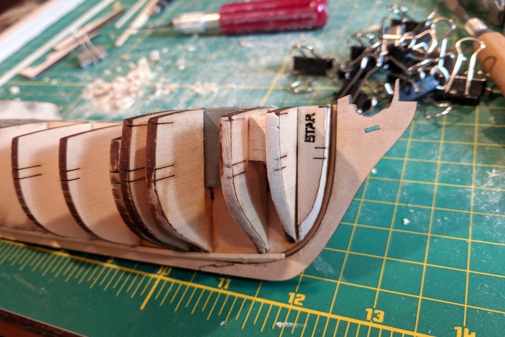
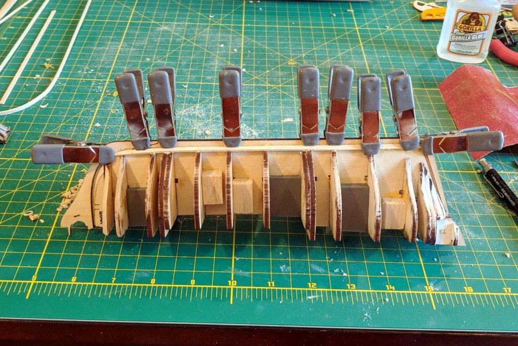
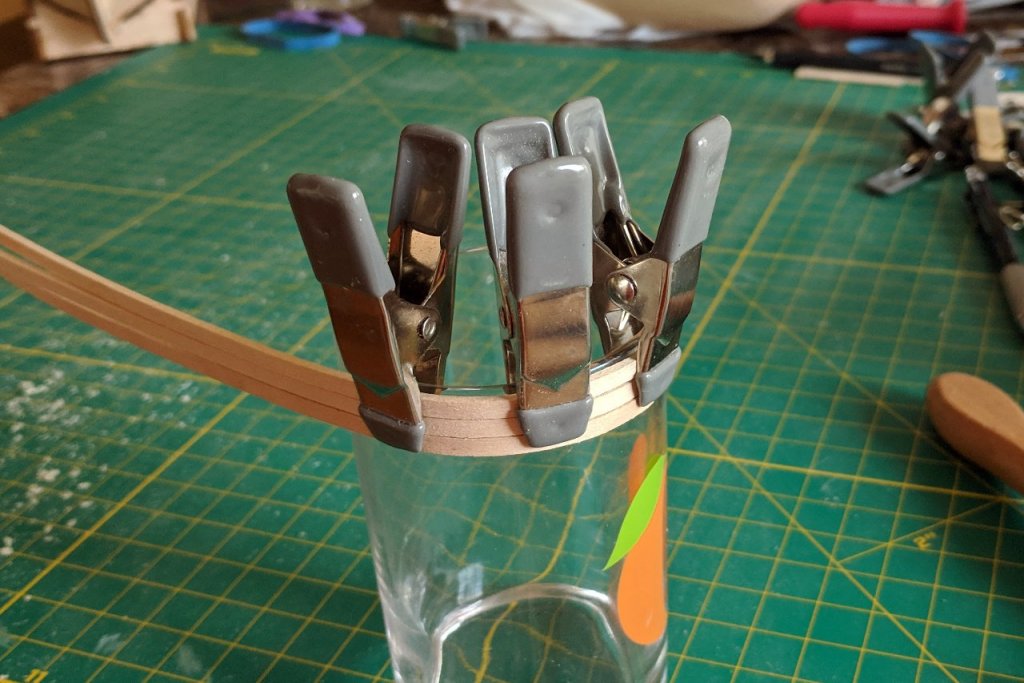
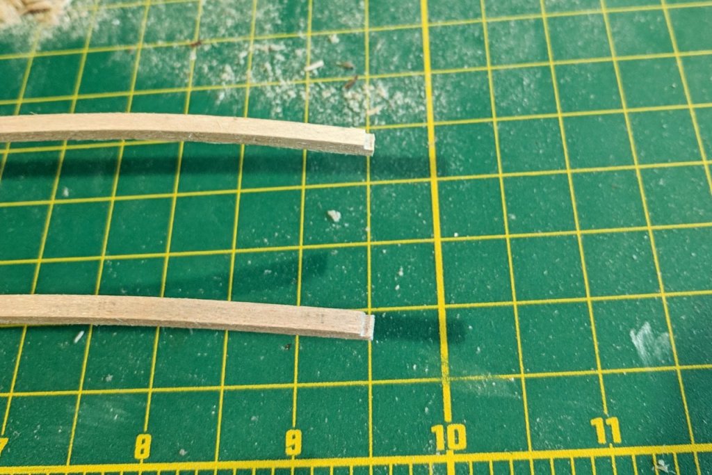
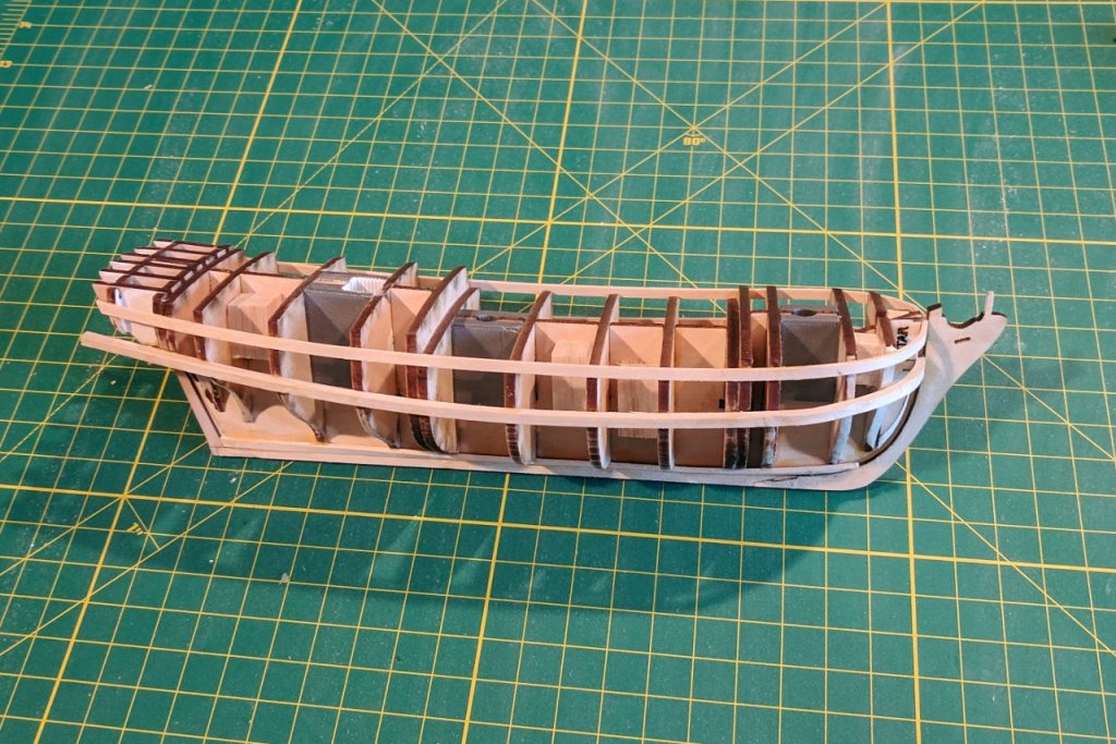
Assembly of the laser-cut pieces is complete (apart from the transom and rudder, which will be added later). Some observations: The keel ended up being a little short. I added a little block at the end to fill in the missing material. I think the error is from underestimating the thickness of the rabbet strip. (You might also notice the garboard plank there. I forgot to take a picture before that was added.) Oops. There is a little gap between the bow former on the starboard side and the first bulkhead. I didn't notice the mistake until after the glue had dried. The port side is fine. I don't want to reglue the piece, so I'll just sand it down a little extra beyond the fairing line. Note the reference marks on the pieces. The upper marks indicate the bottom edge of the bulkheads. The lower pair of marks indicate the run of the wale. The corner of this transom piece sticks out too much and needs to be sanded down to match the curve of the hull. And now to start the planking. As I mentioned above, the garboard was added first. The area below the bearding line was sanded down and as you can see in the first picture, the aft end of the garboard fits nicely and matches the thickness of the keel. Next, I wanted to add the strakes which match up to the reference lines. The Schooner Sultana book states that the hull planking is 2 1/2" thick, average 8" wide. Scaled down to 1:64, the 1/8" x 1/16" strips I am using for the hull planking are reasonably to scale. To match the curve of the bow, I wet the planks then bend them around a juice glass and allow them to dry. And the strake below the bulwarks line is added. For the wales I am using 1/8" x 1/8" strips instead of 1/8" x 1/16". This will cause the wales to stand out above the surface of the hull. The front of the strips is notched to fit into the rabbet. (In hindsight, it may have been better to use a 1/8" x 1/16" strip here and add a second one on top of it later. Bending the thicker strips was a challenge.) The current state of the model.


- 222 replies
-
- 4
-
-
- sultana
- model shipways
- (and 1 more)
-
Welcome to Model Ship World, Matt. You've caught the attention of the three of us with the most recent completed build logs of the Virginia 1819 kit. I'll be following along and would be happy to provide whatever help I can.
- 68 replies
-
- 4
-
-
- virginia 1819
- artesania latina
- (and 1 more)
-
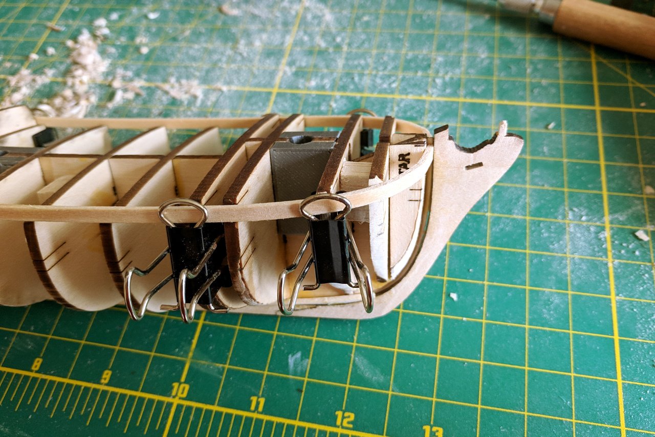
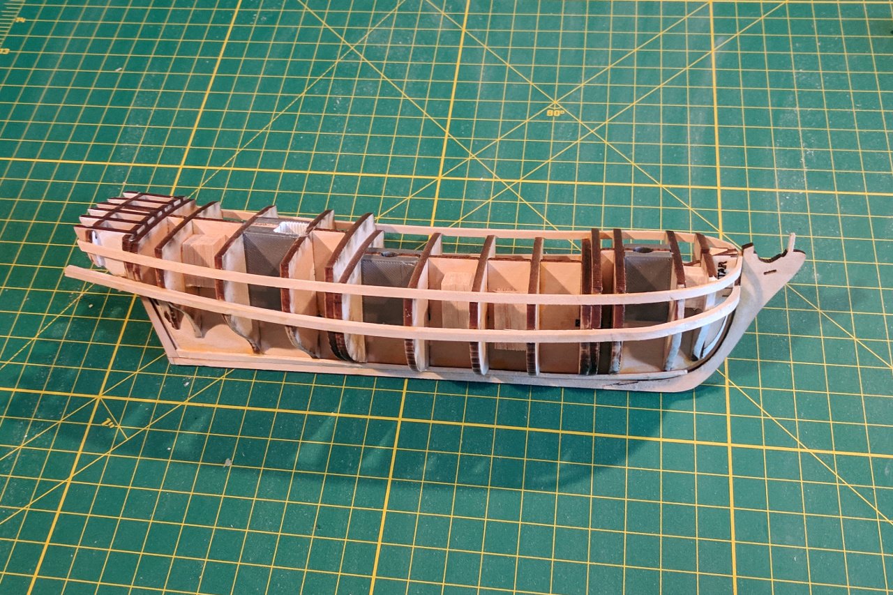
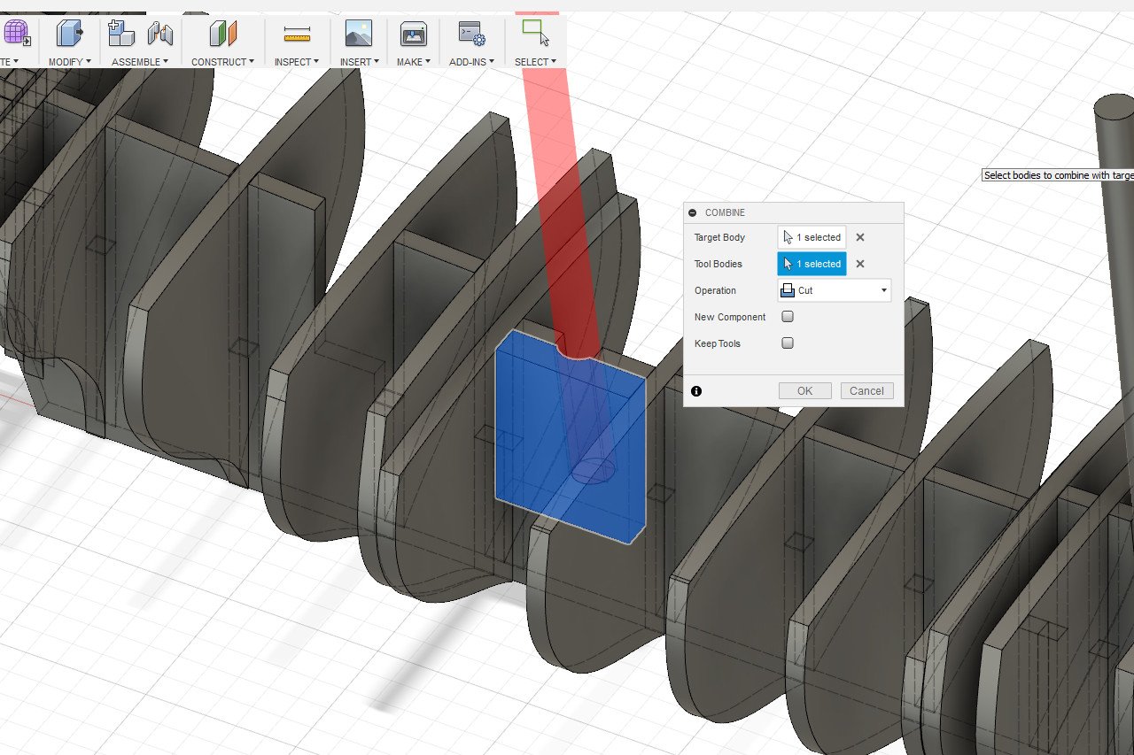
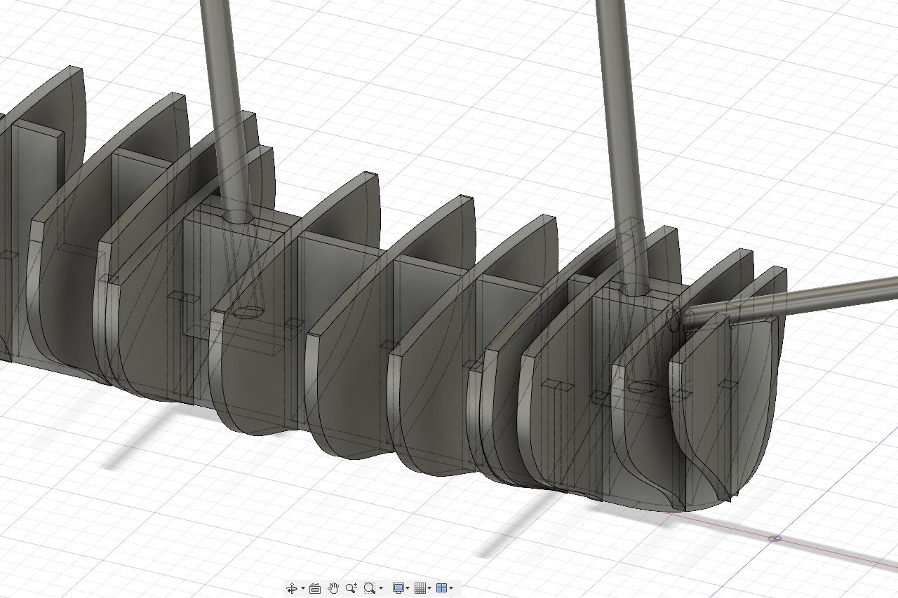
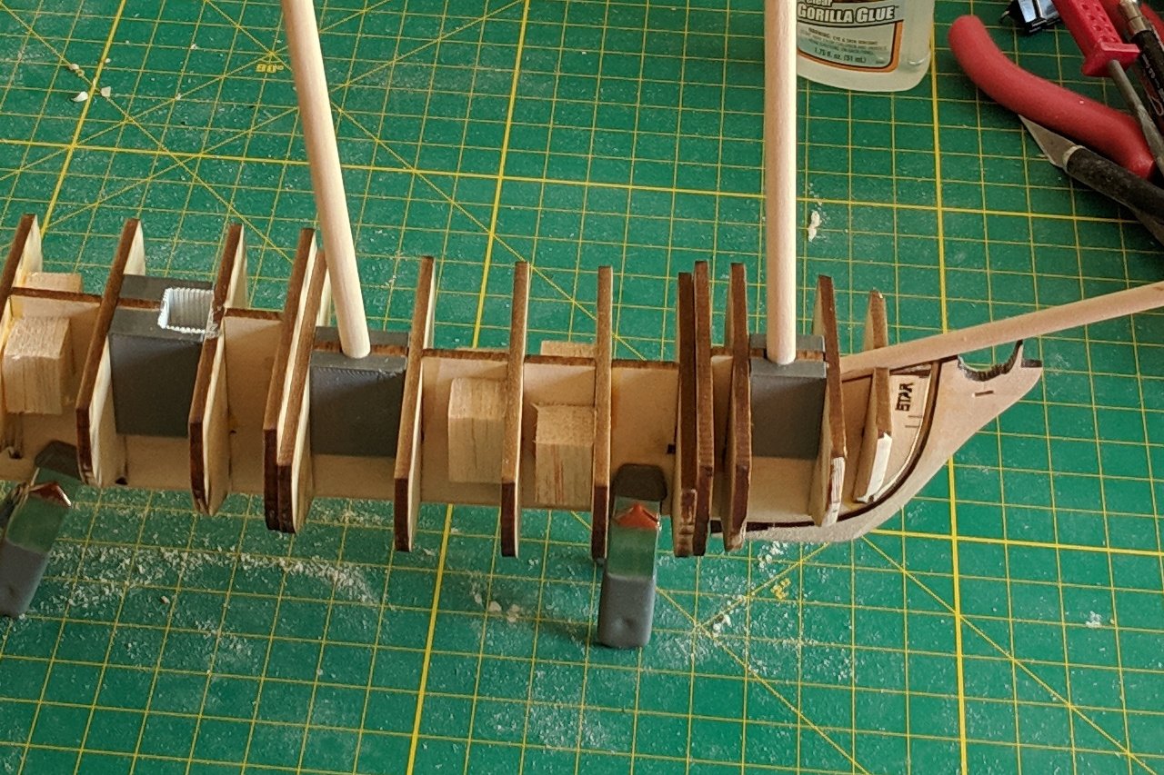
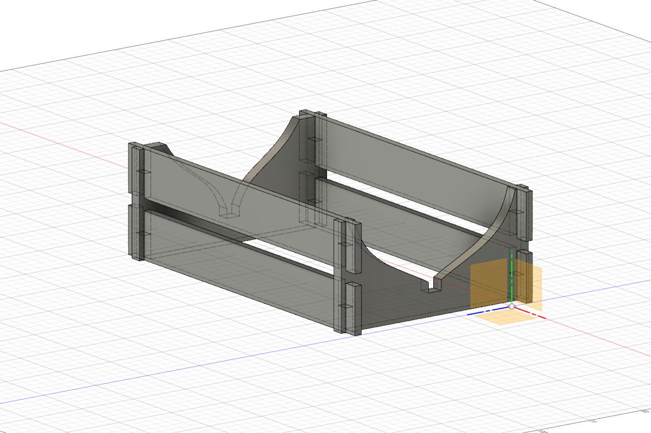
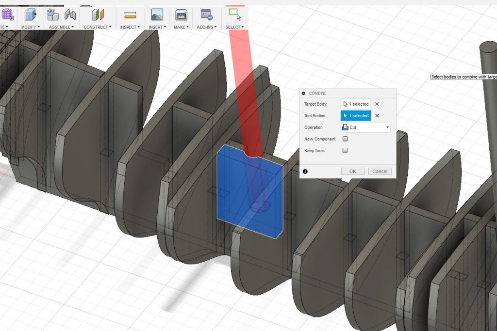
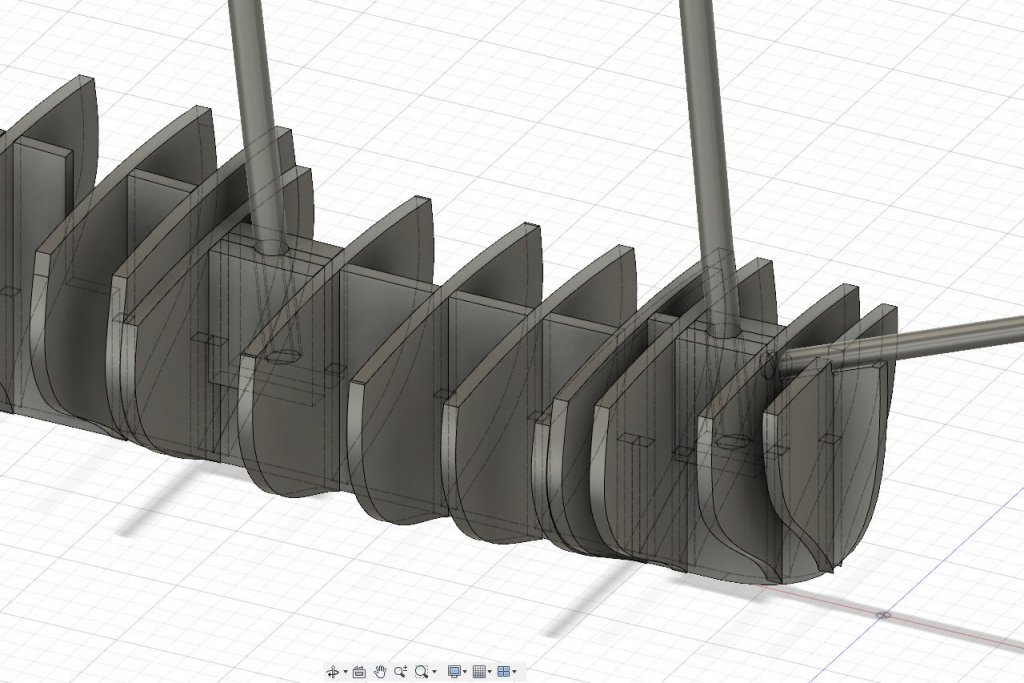
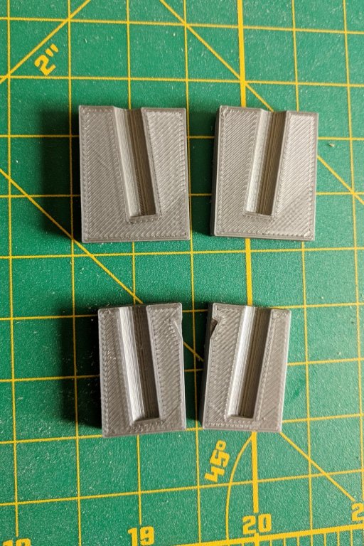
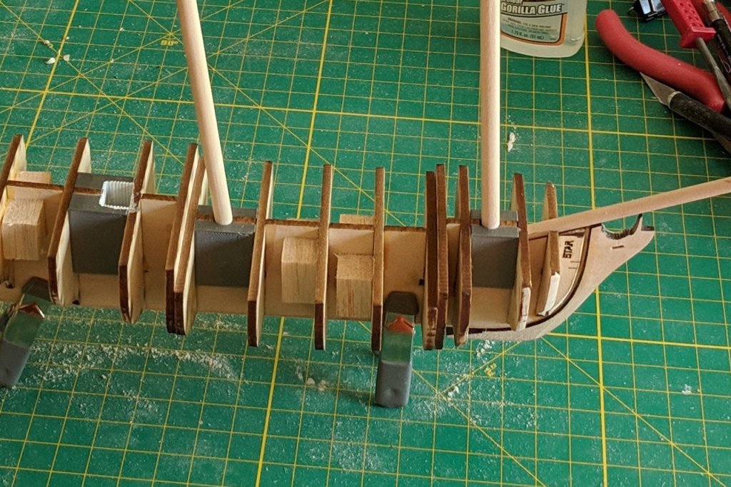
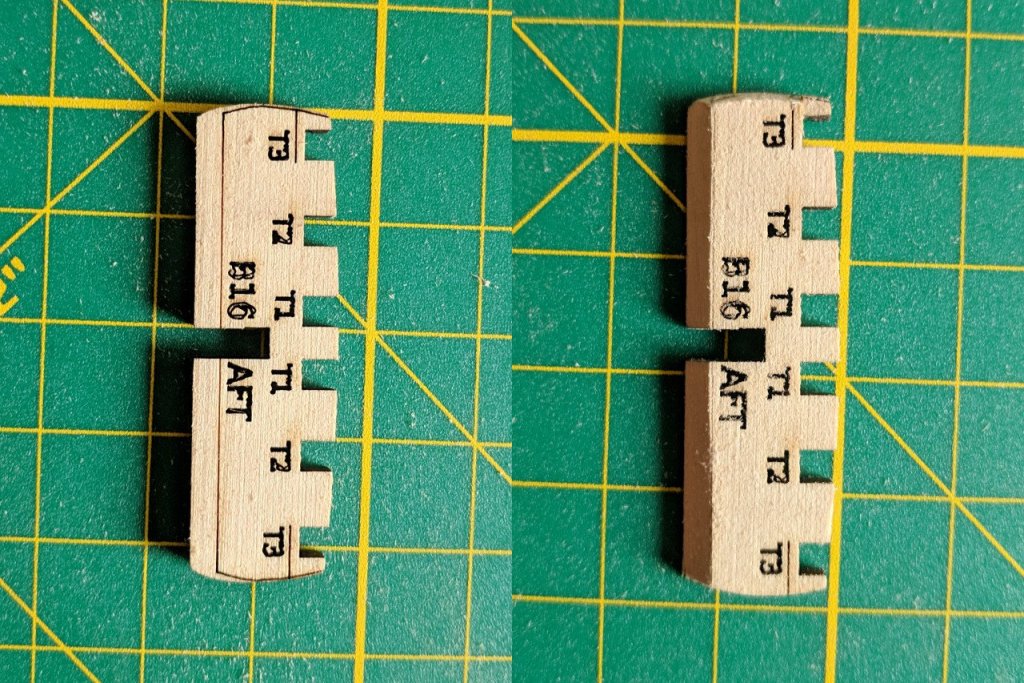
On the false keel, the cutouts for the masts are simple notches. The notches establish the forward and back angle, but do nothing to prevent side to side movement. Let's go back to Fusion 360 and imagine a part that fits on either side of the mast to hold it in the correct position. This is done in Fusion 360 by creating a little block and then subtracting the mast shape from it. The block is sized to fill the space between the bulkheads, so it also acts as a filler block to reinforce the bulkheads. A total of four pieces are designed, two per mast. And then they are 3D printed. Here are the pieces in place. The dowels for the masts and bowsprit have been test-fit into their respective holes. I also 3D printed the aft hatch opening. It was created with a texture and painted to simulate the white wood paneling of the interior of the ship. Also, at the point this picture was taken, I had glued on the stem piece.
- 222 replies
-
- 7
-
-
- sultana
- model shipways
- (and 1 more)
-
What would you suggest? I have already purchased basswood strips for the hull and deck planking. But I'd appreciate suggestions for future projects, even if I'm already committed to what I have for this one.
- 222 replies
-
- 1
-
-
- sultana
- model shipways
- (and 1 more)
-
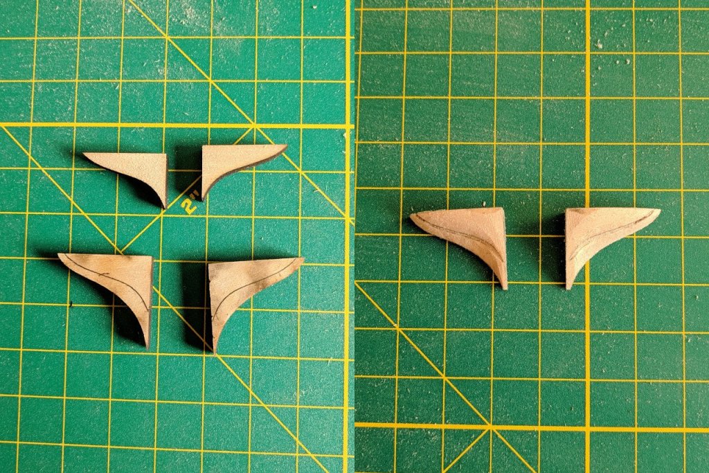
Various pieces were sanded using their engraved fairing lines. These two pieces were glued together and sanded down. They fill the space under the counter. A 1/16" x 1/16" rabbet strip was glued along the false keel. (I jumped the gun and glued one of the bulkheads in place first. I should have glued the rabbet strip first.)


- 222 replies
-
- 5
-
-
- sultana
- model shipways
- (and 1 more)
-
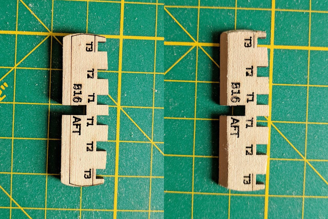
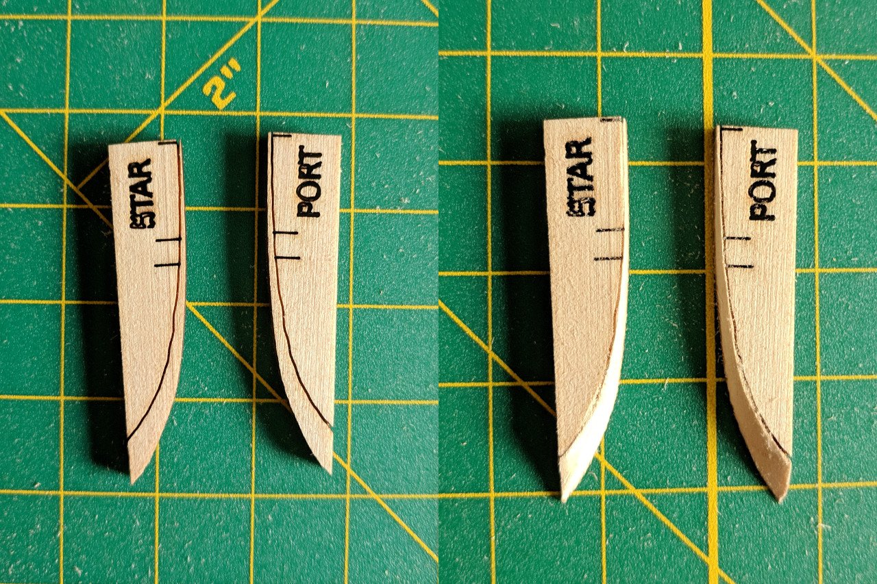
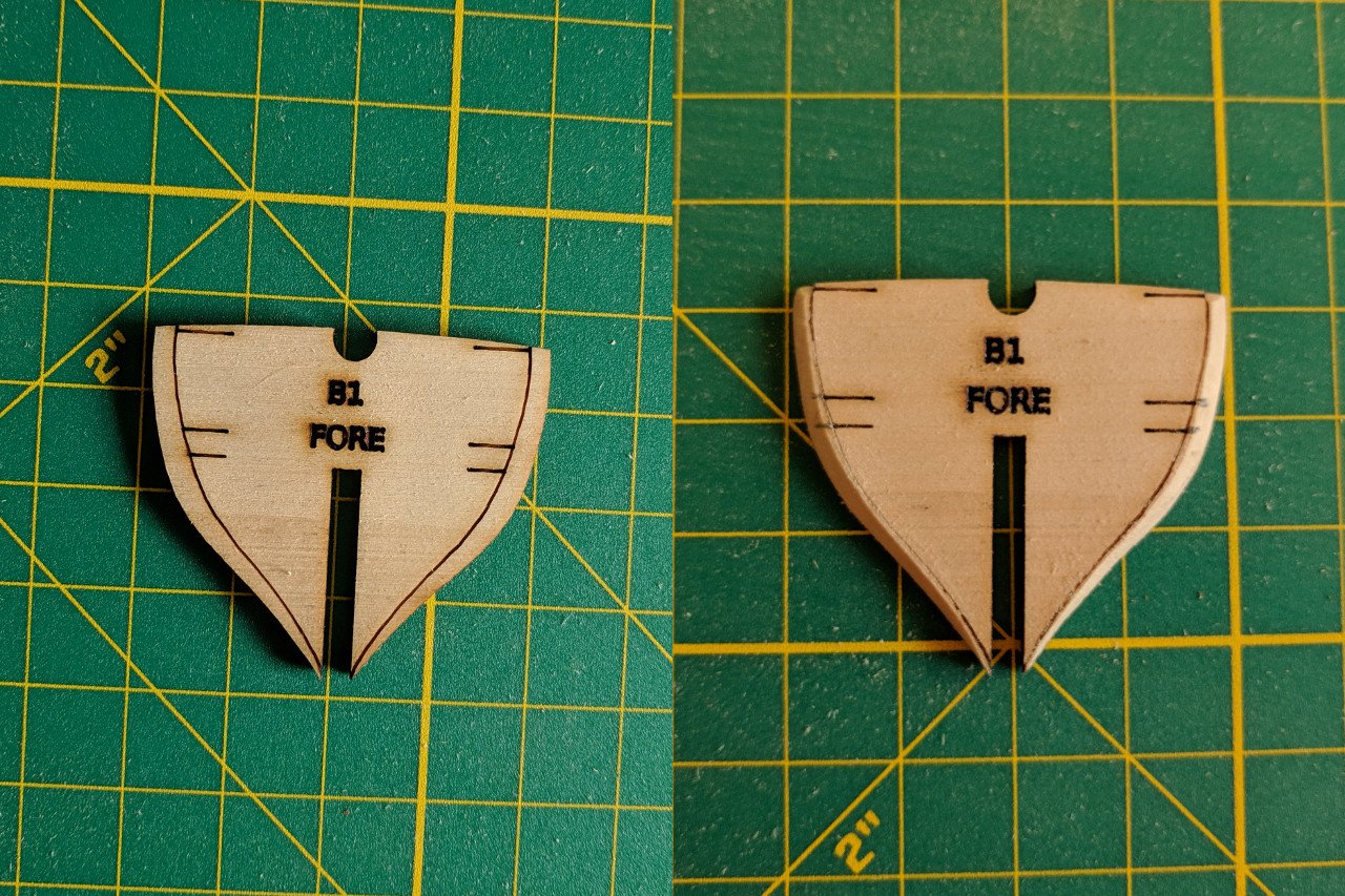
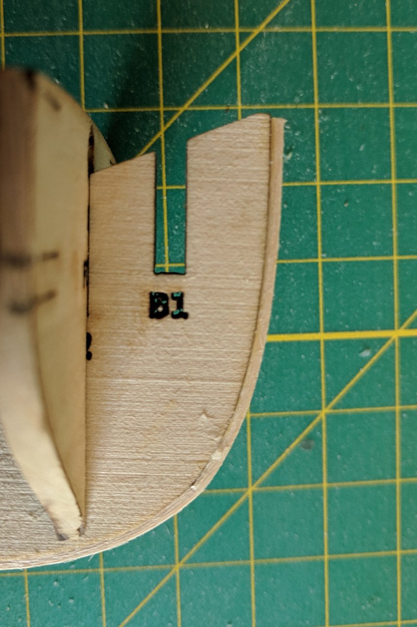
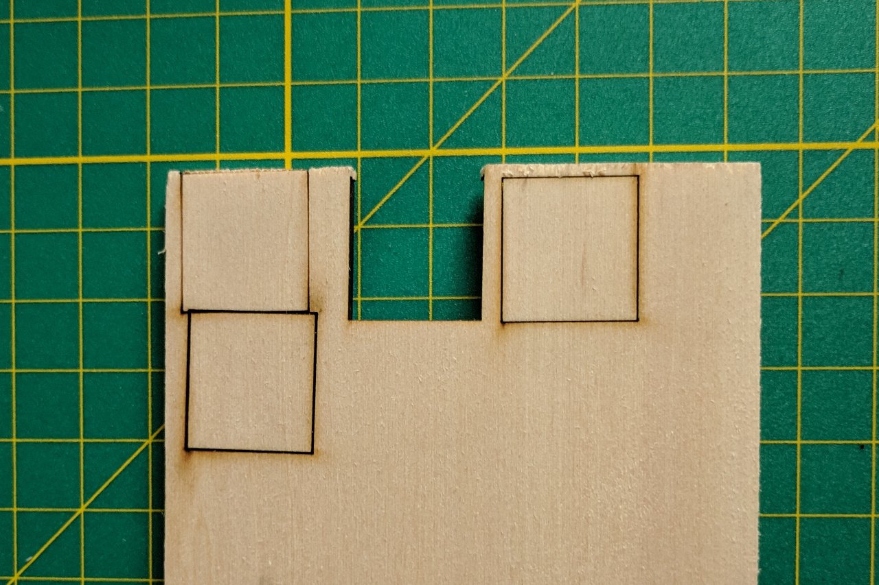
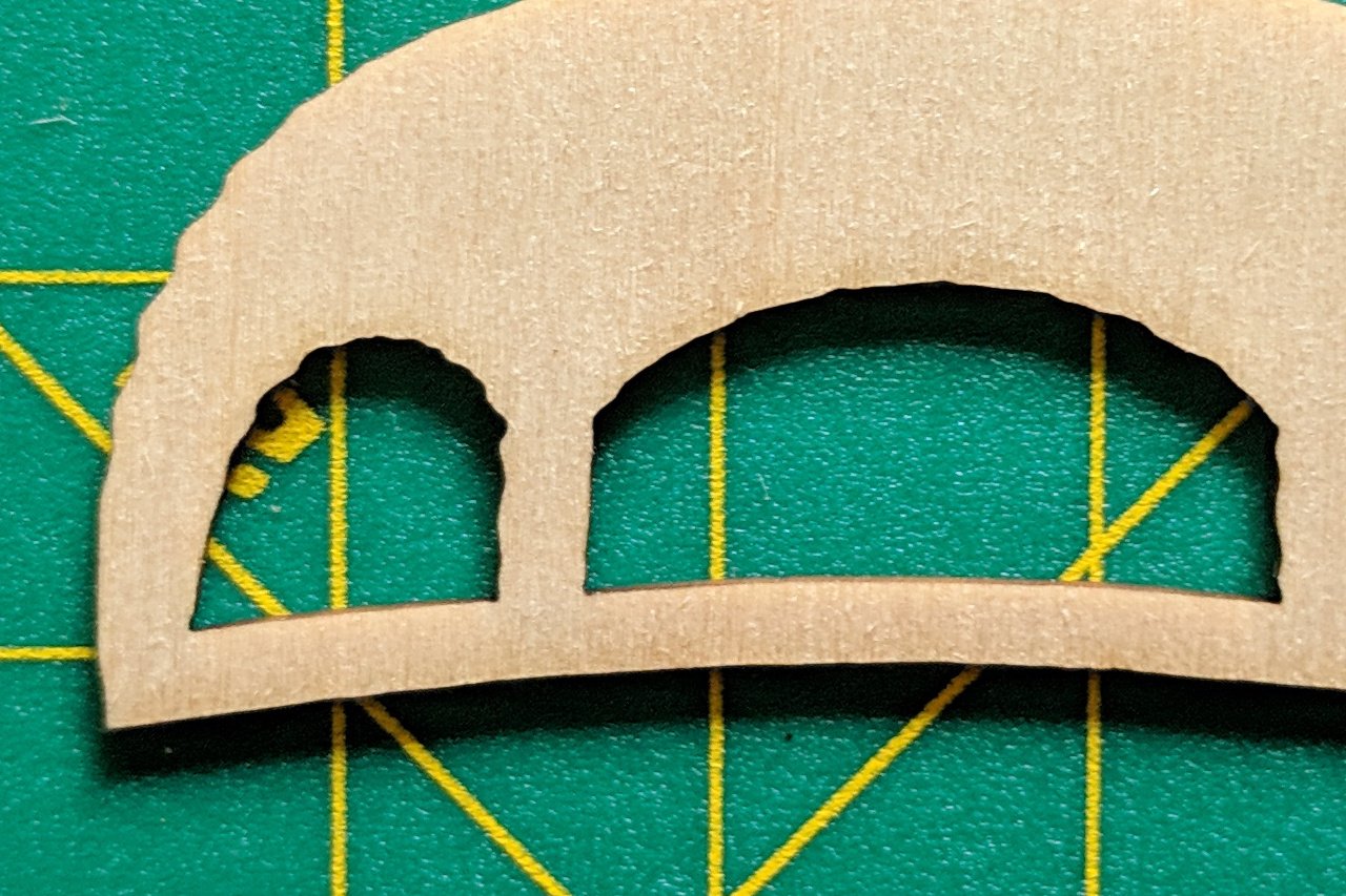
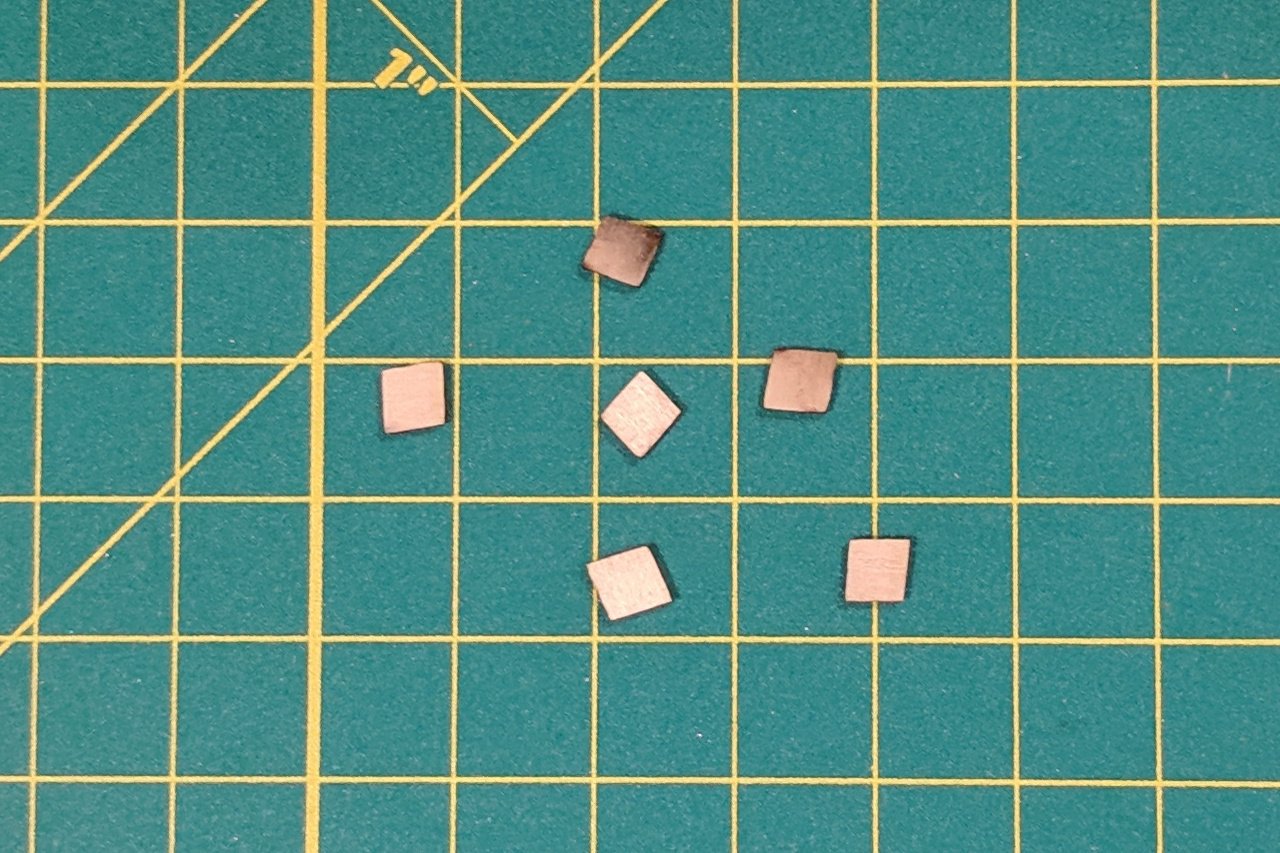
Some notes on laser cutting. The laser cutter I used is an 80 watt model. The strength of the cut is determined by two parameters: power (as a percent of maximum) and speed (in mm per second). The manual listed a recommended setting for cutting 1/8" basswood (50% power, 15 mm/s), and a recommended setting for engraving (14% power, 350 mm/s). I tried the engrave and it worked fine, but I was worried that the cut setting might be too strong. I was right. For 1/8" basswood I found 50% and 50 mm/s speed to cut just through. For my 3/16" sheet the setting I found was 50% power and 30 mm/s speed. And for the 1/32" sheet it was 50% power and 200 mm/s speed. If I had more time I would have experimented with other power settings, but I went ahead with the settings that I knew would work. Some test cuts shown below. After cutting the pieces, I tried a quick test fit and discovered that there was some wobble. I had made a rookie mistake: I didn't account for the thickness of the material cut away by the laser and just assumed a perfect zero thickness line. My later measurements show the laser line is about .3 mm in width. That's small, but enough that the pieces don't slide together perfectly. I'd rather not revise my design and recut, so I'll just be careful about making sure the bulkheads are perpendicular to the keel when I glue them in. Another thing I noticed is that some curved cuts have a wavy rather than smooth line. This is most noticeable on the transom pieces cut from the 1/32" sheet. I have two theories about why this happened. First, it could be related to how I had to save splines as polylines (details in one of my earlier updates). Or it could be a result of vibrations. I did nothing to hold the wood sheets onto the bed while they were being cut, so they may have been moved by vibrations from the machine. Anyway, the wavy lines can be sanded down smooth, so I think it will be ok. Finally, I noticed that the text labels on the pieces were cut very deep. Fairing and reference lines were fine. The issue with the text was a consequence of how I added the text. In Inkscape, I added the text using a san serif font then used Inkscape's object to path tool to convert the text into vector graphics. However, when they were engraved, the laser went over and over the text area to "fill in" the text, causing it to cut some or all the way through the wood. Fortunately, it happens in small enough areas that the model won't be affected. In the future, I should use simpler vector text.


- 222 replies
-
- 5
-
-
- sultana
- model shipways
- (and 1 more)
-
Well, I will be using some parts from the kit, and referencing parts of the kit plans. But you have a point. How much of a kit do you have to use for it to still qualify as a kit build?
- 222 replies
-
- 1
-
-
- sultana
- model shipways
- (and 1 more)
-
At a local Makerspace. I took a training class on how to use the laser cutter last year and did all the laser cutting this evening using the equipment belonging to the Makerspace. Just the thickness of the wood sheets. I used basswood because it's inexpensive and easy to get. (And because I really don't know much about the properties of other types of wood.) Maybe using a harder wood would have been better. I don't know. Yes, yes, YES! This is my Sultana build log, not a product development log. 😀 Completing the laser cutting is just the end of chapter one. I'm a long way from being done. I'm doing all this for fun. Like I said before, I'll share something once I have a complete, or nearly complete, model.
- 222 replies
-
- 3
-
-
- sultana
- model shipways
- (and 1 more)
-
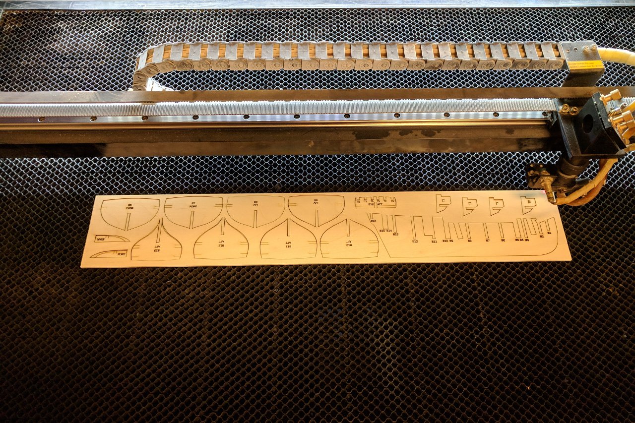
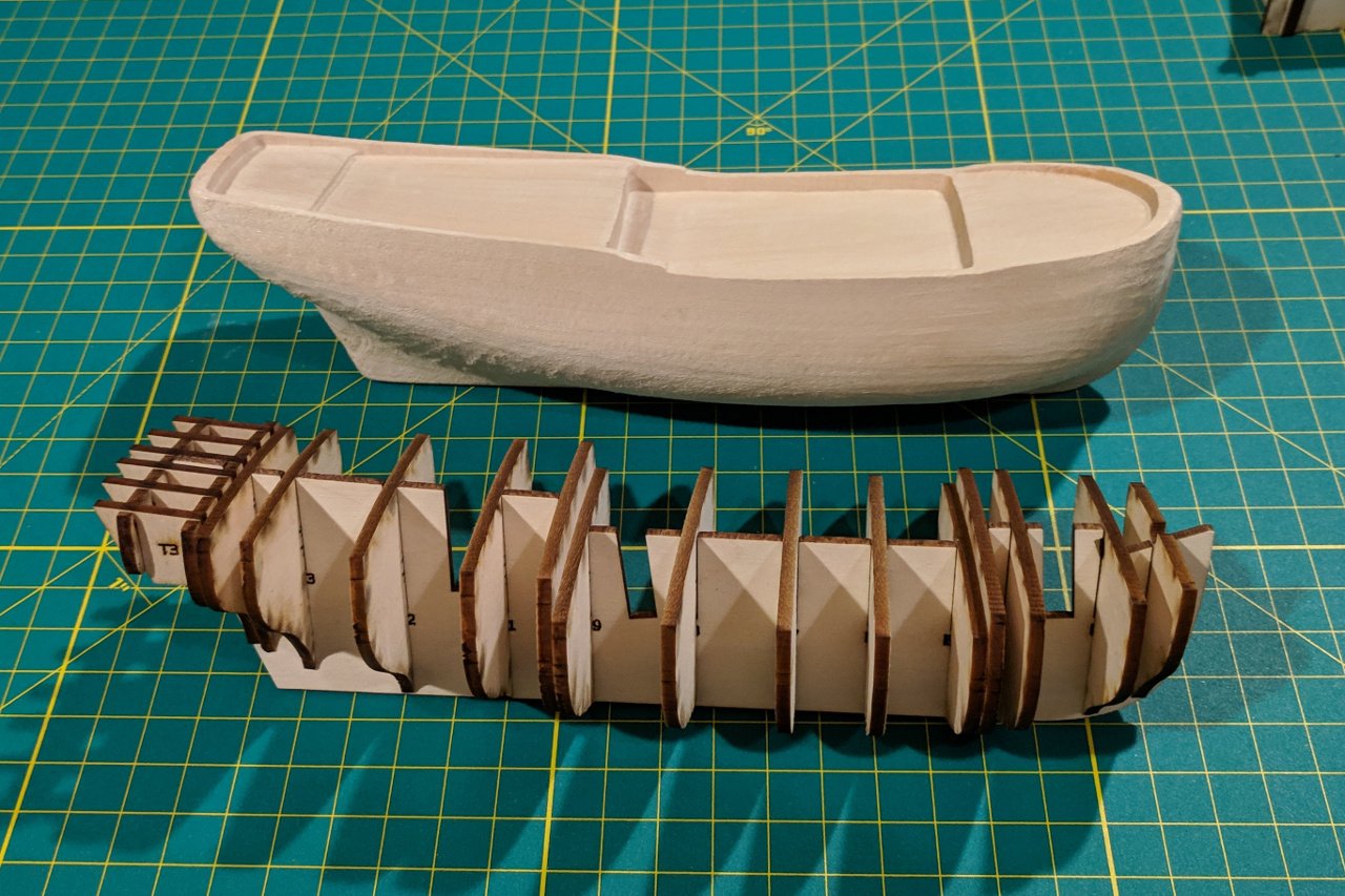
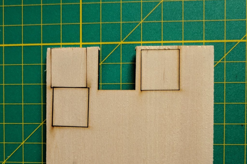
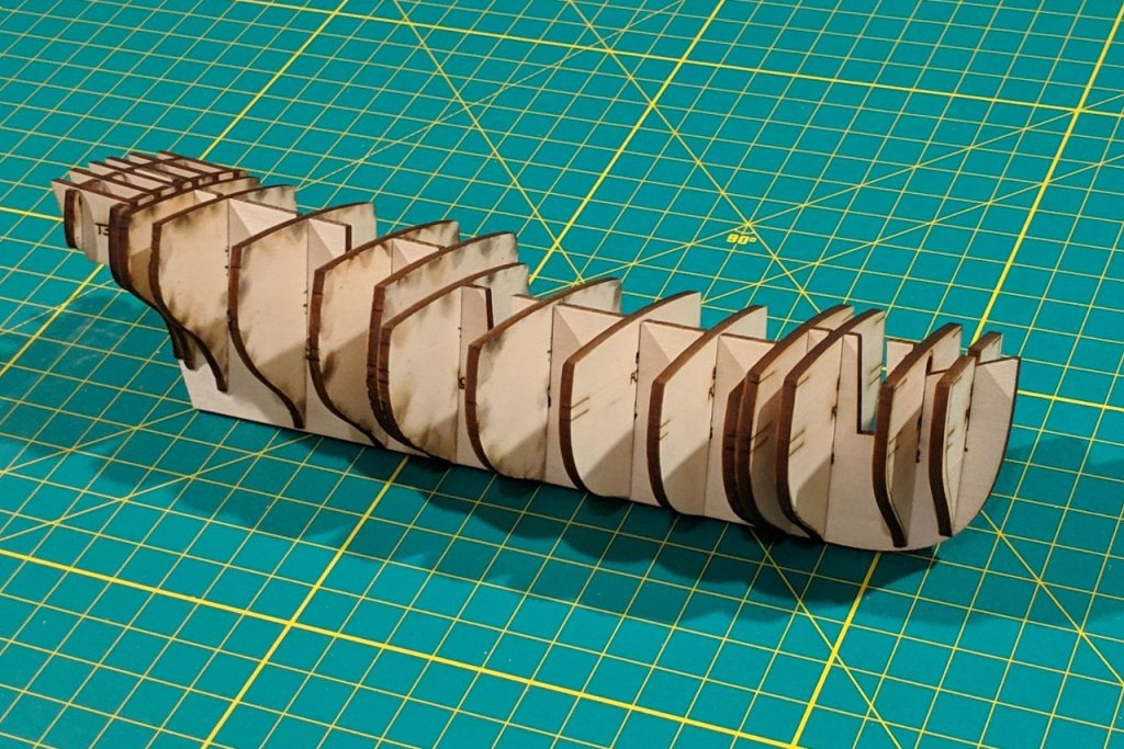
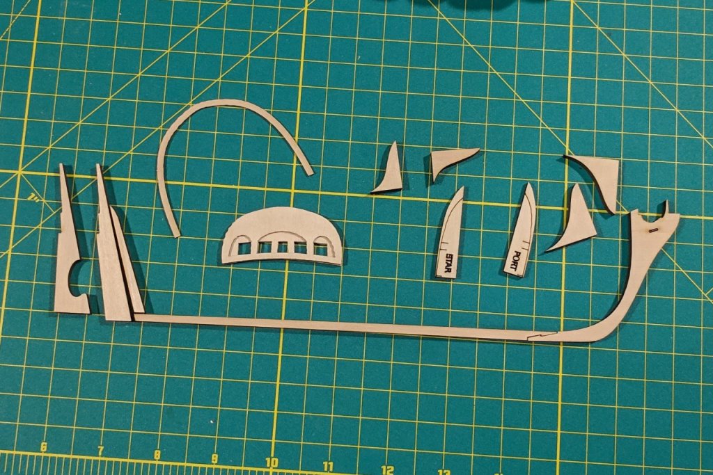
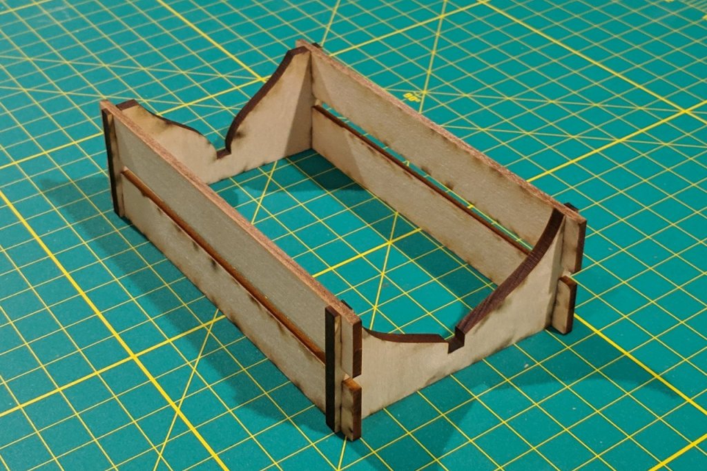
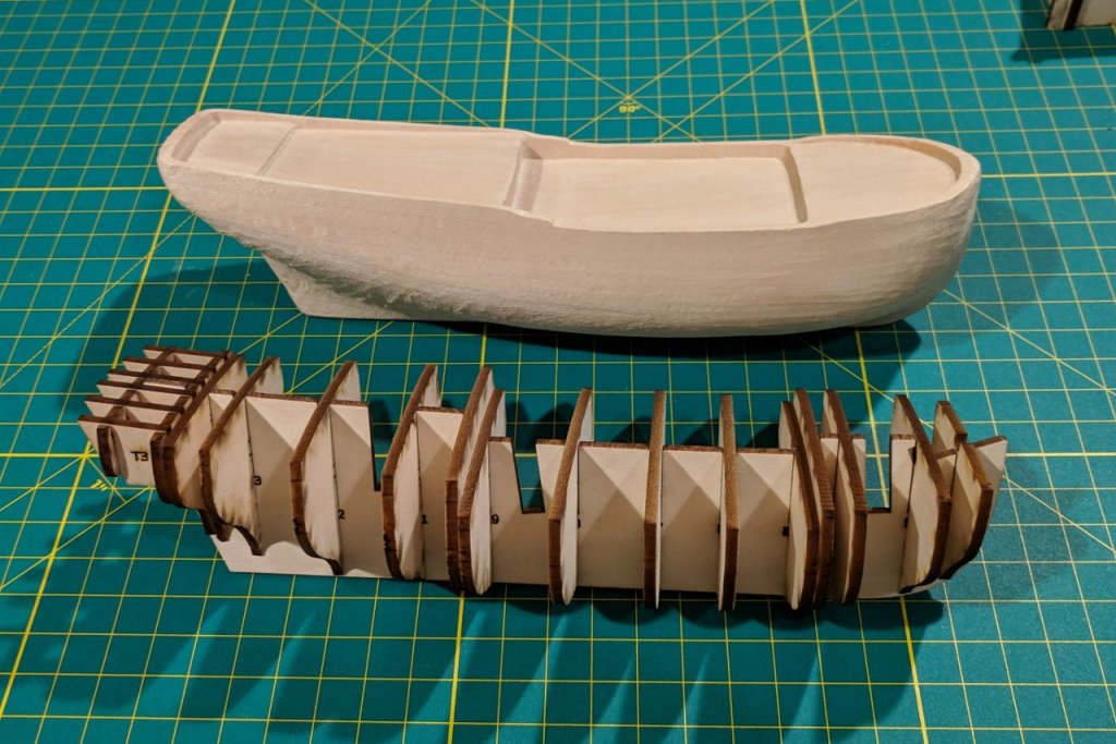
Sick of screenshots? Want to finally see some actual, physical pieces of wood? Well, I've been grinning ear to ear because I finally got my pieces laser cut! Here's one of the sheets after cutting. (I should have taken more pictures of the laser cutter in action, but I was too focused on getting the work done.) Here is a picture of the design, followed by the corresponding pieces dry fit. And various other pieces. Because someone requested it (hi, Patrick), the classic rudder is there as well as the modern rudder. This is my cradle for holding the ship while I work on it. And the laser cut pieces next to the original solid hull. Well, I kept the little bits that were cut out (see below), but probably won't use them. I have other ideas for the windows. Next time, a closer examination of the pieces and some lessons learned about laser cutting.


- 222 replies
-
- 9
-
-
- sultana
- model shipways
- (and 1 more)
-
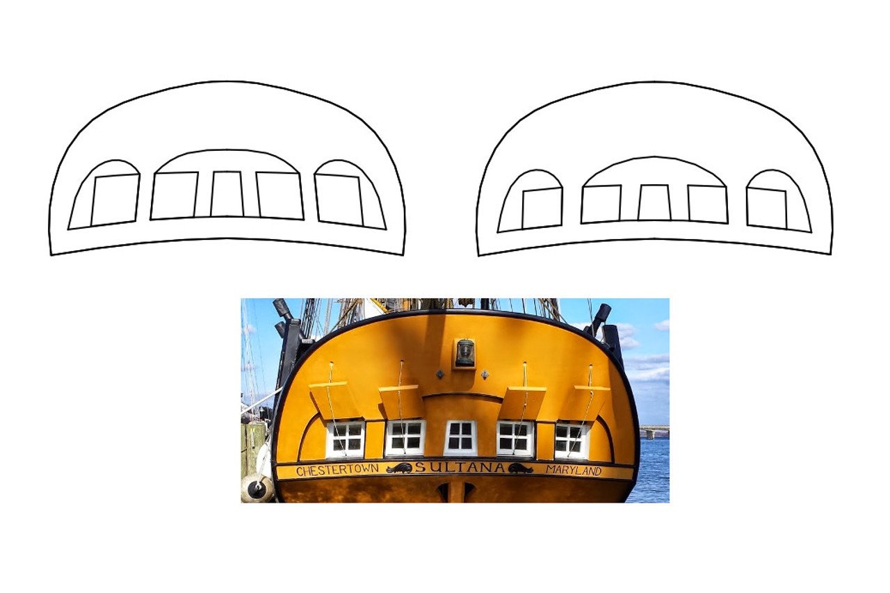
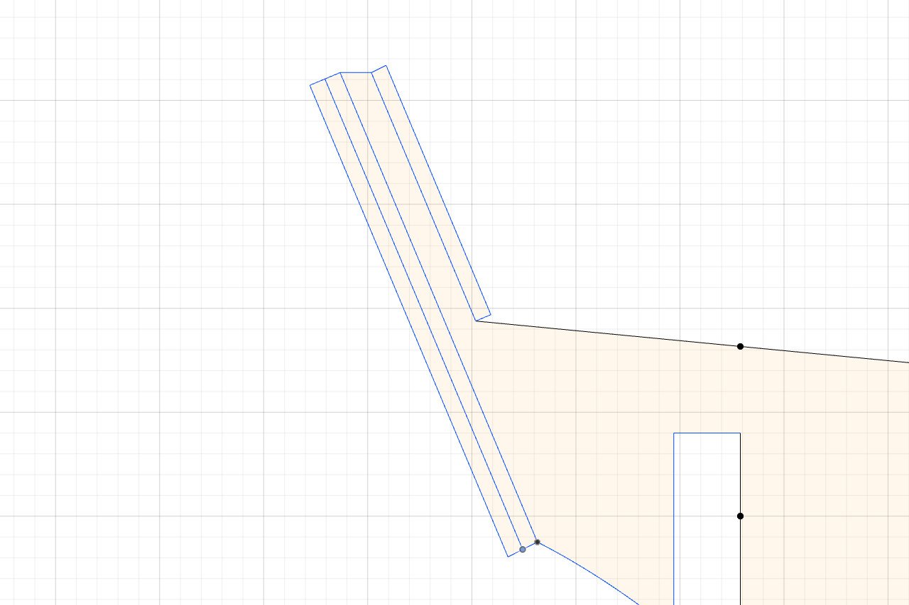
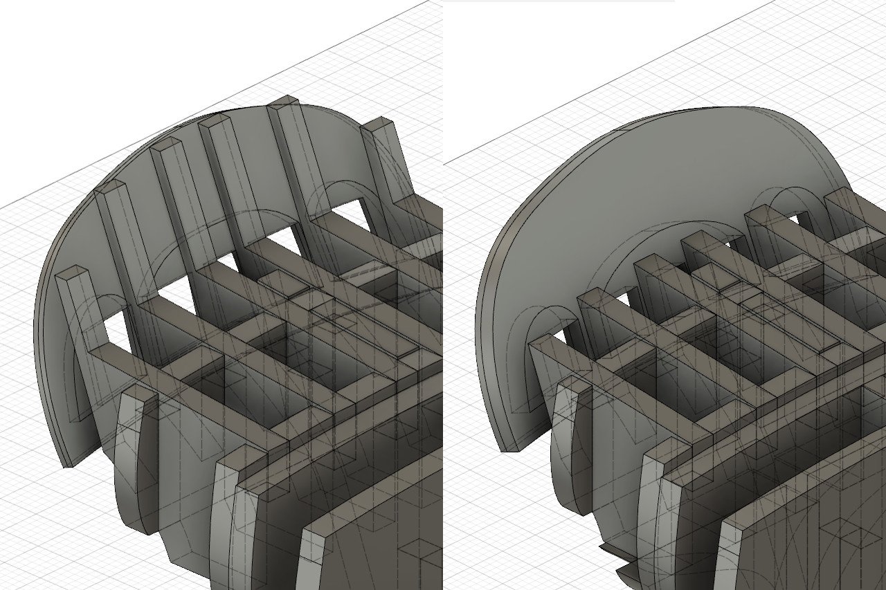
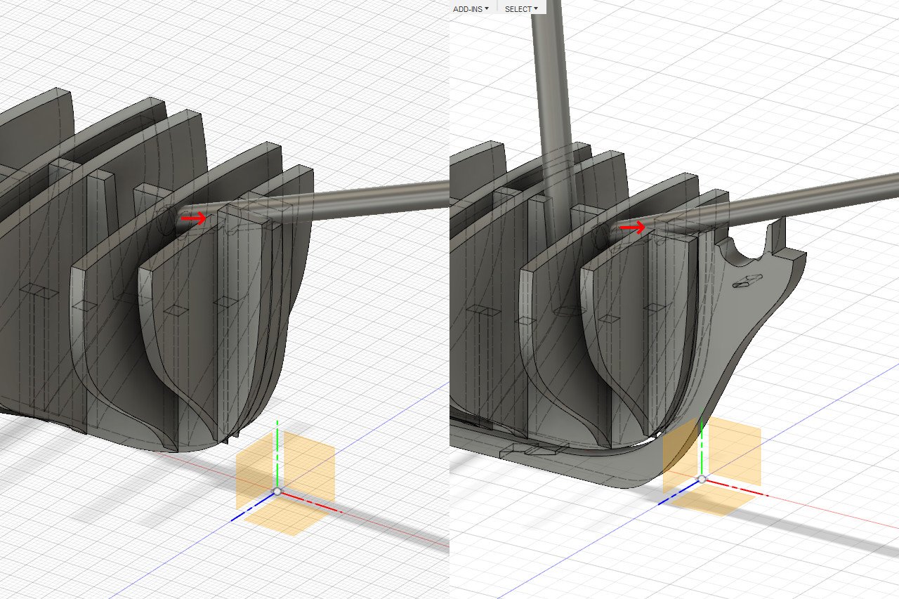
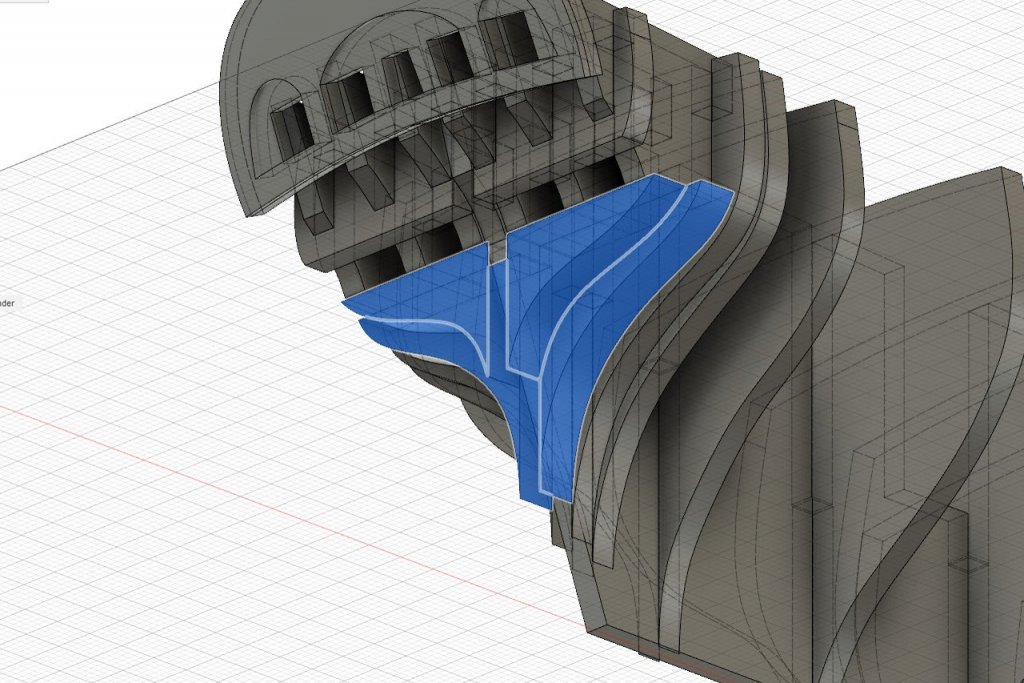
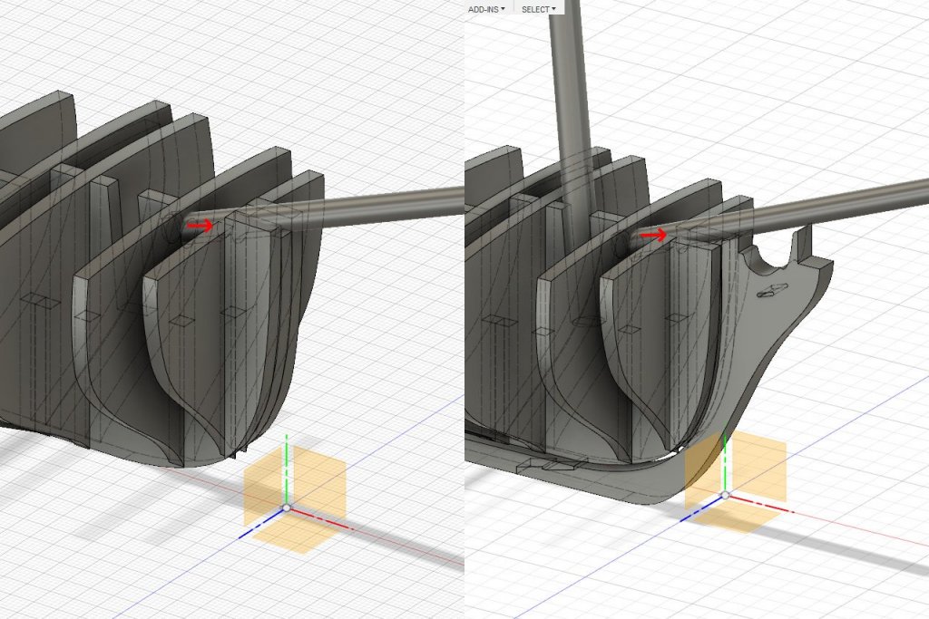
More design changes. First, I was concerned because there was no surface under the counter for the end of the hull planks to sit on. So, new shapes were added there. The new pieces are highlighted in blue in the picture. I was not happy with the transom windows, recess, etc. I spent some time redesigning the shapes and it now is closer to what's in my reference picture. Original attempt is on the left, new version is on the right. Originally I planned to glue the transom end piece above to simulated stern timbers, and also add some planking to cover the stern timbers on the inside. See the basic idea in the picture below. All those layers together is pretty thick, and trying to make the stern timbers thinner would only make then so thin that they would break easily. I realized that I don't need the stern timbers. There is already enough surface area for the pieces to be glued on, so the stern timbers were removed from those pieces. Instead, I will cut 3 transom pieces from 1/32" sheet: one with the recess pattern and two with the windows cut out. This stack will be glued directly on the back, very much as in the original Model Shipways plans.


- 222 replies
-
- 6
-
-
- sultana
- model shipways
- (and 1 more)
-
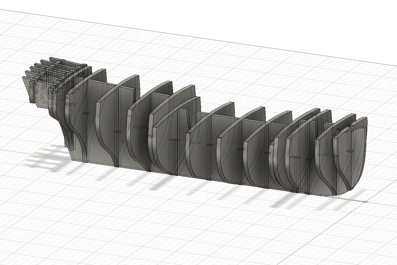
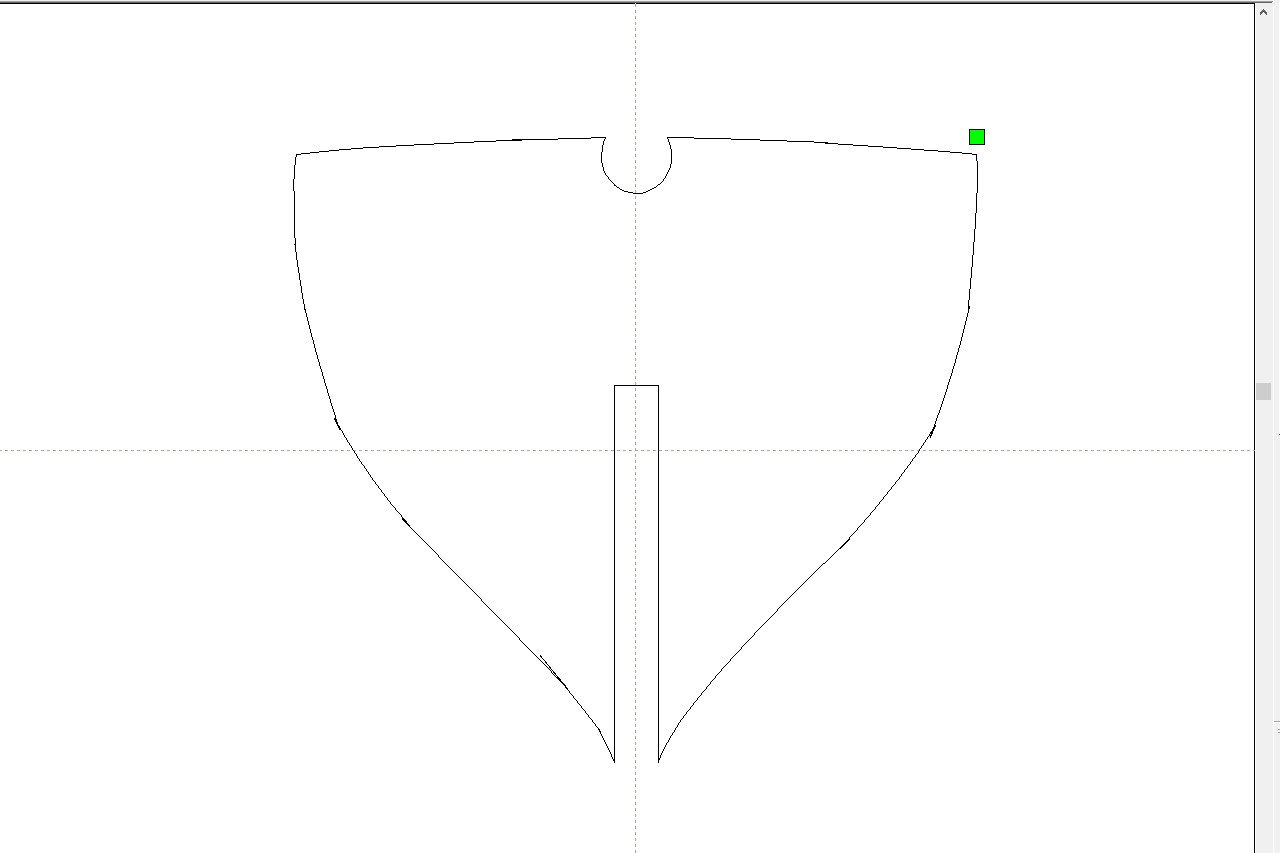
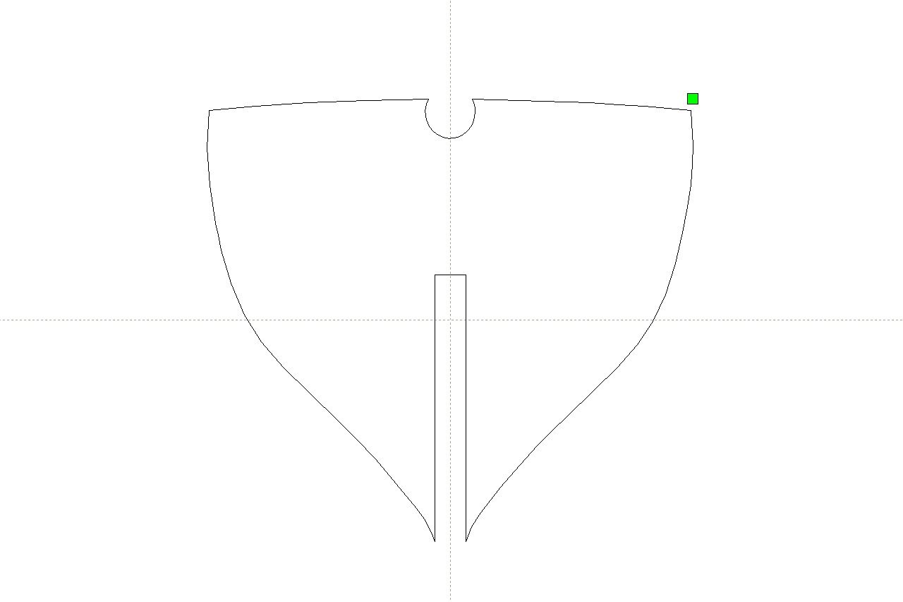
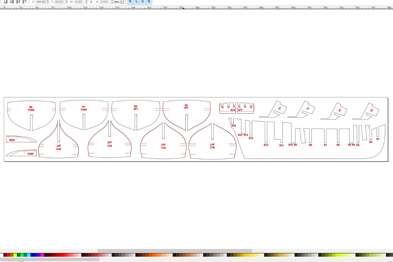
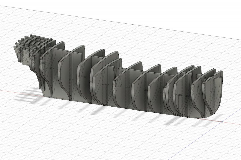
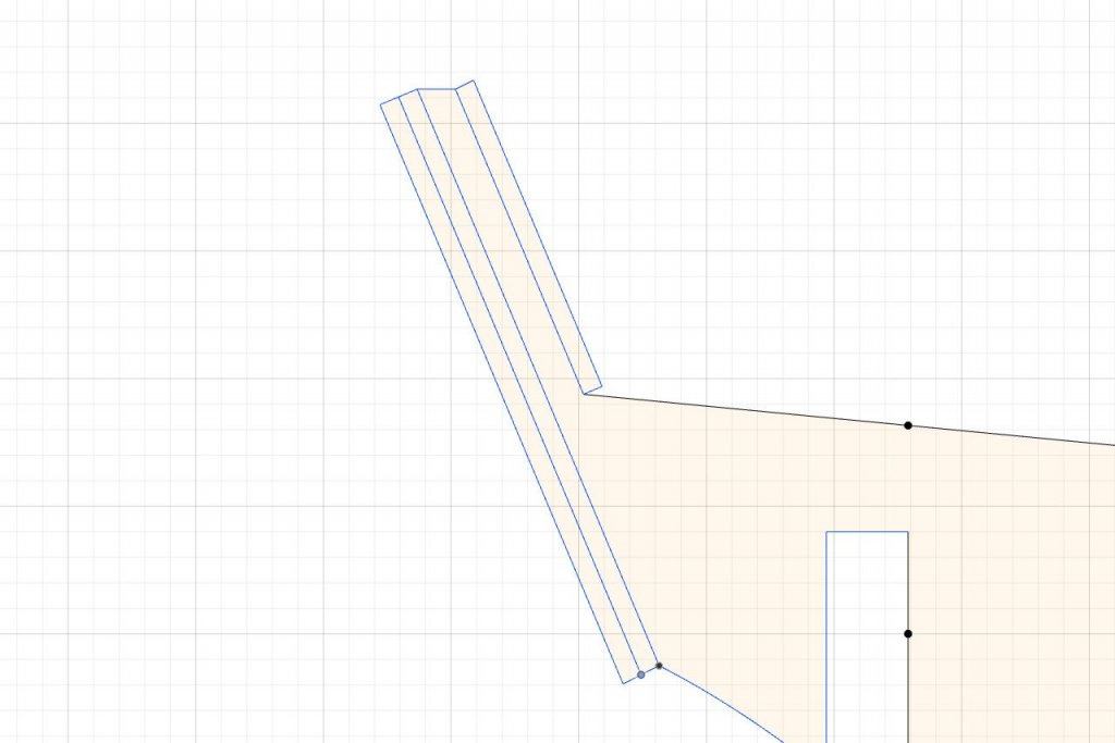
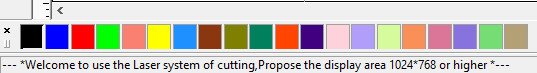
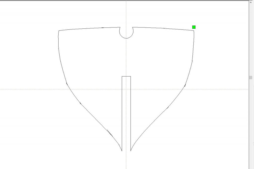
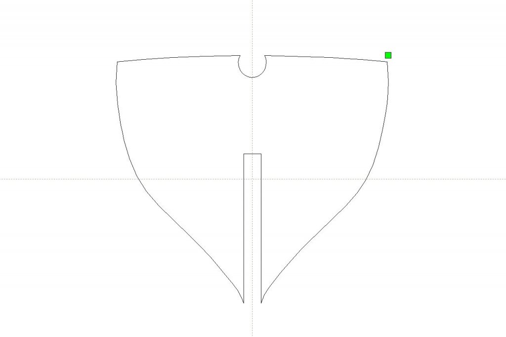
I caught an error in my design. The bow former pieces end at a level that is too high. I corrected them and now they end flush with the forecastle deck level. I hope there are no other errors that I have overlooked. Ok, let's get ready for laser cutting. The laser cutter software is called RDWorks. It has some basic tools to create and modify shapes, but... Well, have a look at the message that appears at the bottom left of the RDWorks window. I think it says it all. I tried exporting one of the bulkhead shapes from Fusion 360 as a DXF and importing it into RDWorks. There is a problem. Notice how the edges of the shape aren't smooth and sometimes overlap. This is not a problem with RDWorks. I found lots of people complaining about issues with the DXF export function in Fusion 360. Apparently, it outputs splines in a format that many other programs can't handle. The solution I found is a Fusion 360 plug-in called "DXF Spline To Polyline". The plug-in adds a separate DXF export option to Fusion 360 that converts splines to many short line segments. Here is the same bulkhead piece exported using the plug-in then brought into RDWorks. Once I confirmed that the plug-in was working as expected, I exported every shape (bulkheads, fairing lines, keel, rudder, transom, etc.) as a separate DXF file. There were 51 in all. It was pretty clear that arranging the parts for cutting using RDWorks would be a pain. I found some strong recommendations for the popular open-source vector graphics software Inkscape. Learning the basic operations within Inkscape didn't take long. In Inkscape, I created a new document with a size equivalent to a 24" x 4" wood sheet. Then I imported a DXF and moved it into place. For items that will be scribed rather than cut, I set the color to red. Labels were adding to pieces using the text tool. However, in order to make sure they would be scribed by the laser cutter, I had to convert the text objects into paths using the Path -> Object to Path menu option. When the whole Inkscape document is saved as a DXF then imported into RDWorks, RDWorks will interpret each color as a layer, so the separation between the lines to scribe and lines to cut is preserved. Here's the first sheet of objects. I will end up with four total.

- 222 replies
-
- 4
-
-
- sultana
- model shipways
- (and 1 more)
-
Since you mentioned it, I'll keep both rudder versions in the design. Anyway, while working on the layout for cutting, I realized that I'll have some extra space. So I designed a cradle for the model to sit in while I work on it.

- 222 replies
-
- 2
-
-
- sultana
- model shipways
- (and 1 more)
-
In your second picture I can't help but notice the telltale orange wireframe of Blender. Was all this work done in Blender?
-
Laser cutting questions
SardonicMeow replied to SardonicMeow's topic in Modeling tools and Workshop Equipment
Thanks for all the responses. Lots of options to consider. -
Laser cutting questions
SardonicMeow replied to SardonicMeow's topic in Modeling tools and Workshop Equipment
Interesting. I didn't know that not all plywood is created equal. Where would I get quality plywood and how would I know it's good? I should have mentioned in my original post that all the laser cut pieces will be planked over and/or painted over, so the appearance of the wood doesn't matter to me. -
I'm working on a laser cut plank-on-bulkhead project and could use some advice from anyone who has done the same. My design is complete and I have been trained on the use of the laser cutter at my local Makerspace. So, I'm almost ready to proceed to the cutting. My first question is what wood to use. I know I don't want to use plywood, because I had issues with the plywood layers coming apart when I built the Virginia 1819 kit. Is basswood definitely out? My design has some delicate parts, so I guess basswood would be too easy to break? So what about cherry? Maple? Alaskan cedar from a certain someone? I really don't know how the different hardwoods compare. My design assumes sheets will be 1/8" thick. To what extent should I consider the grain direction when aligning parts? It seems obvious that long, skinny pieces should be aligned with the grain, but are there any other gotchas? How narrow can I safely cut parts? I have a few parts with sections that narrow to less than 2mm. Is that doable or will cuts that close together get burned through? Thanks in advance for your help.