HOLIDAY DONATION DRIVE - SUPPORT MSW - DO YOUR PART TO KEEP THIS GREAT FORUM GOING! (Only 13 donations so far - C'mon guys!)
×


SardonicMeow
-
Posts
333 -
Joined
-
Last visited
Content Type
Profiles
Forums
Gallery
Events
Everything posted by SardonicMeow
-
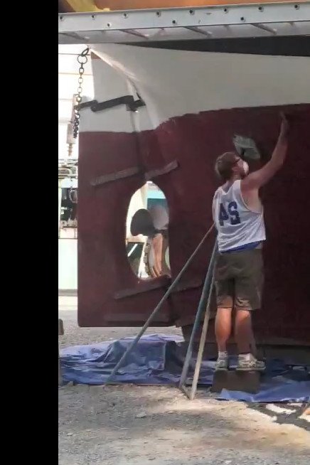
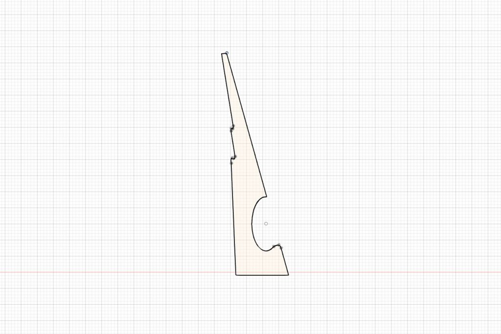
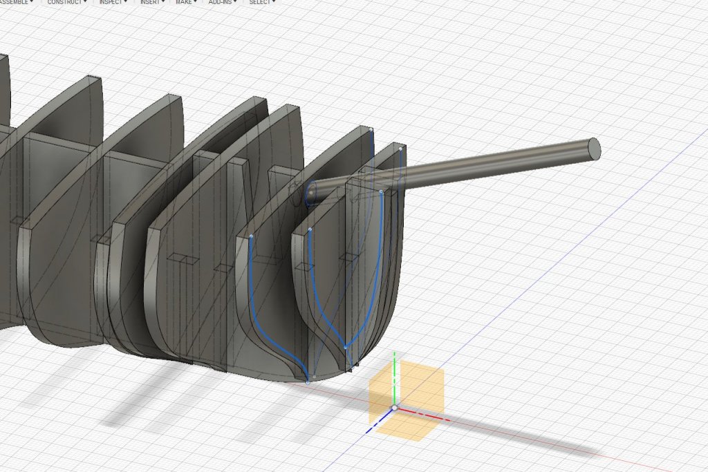
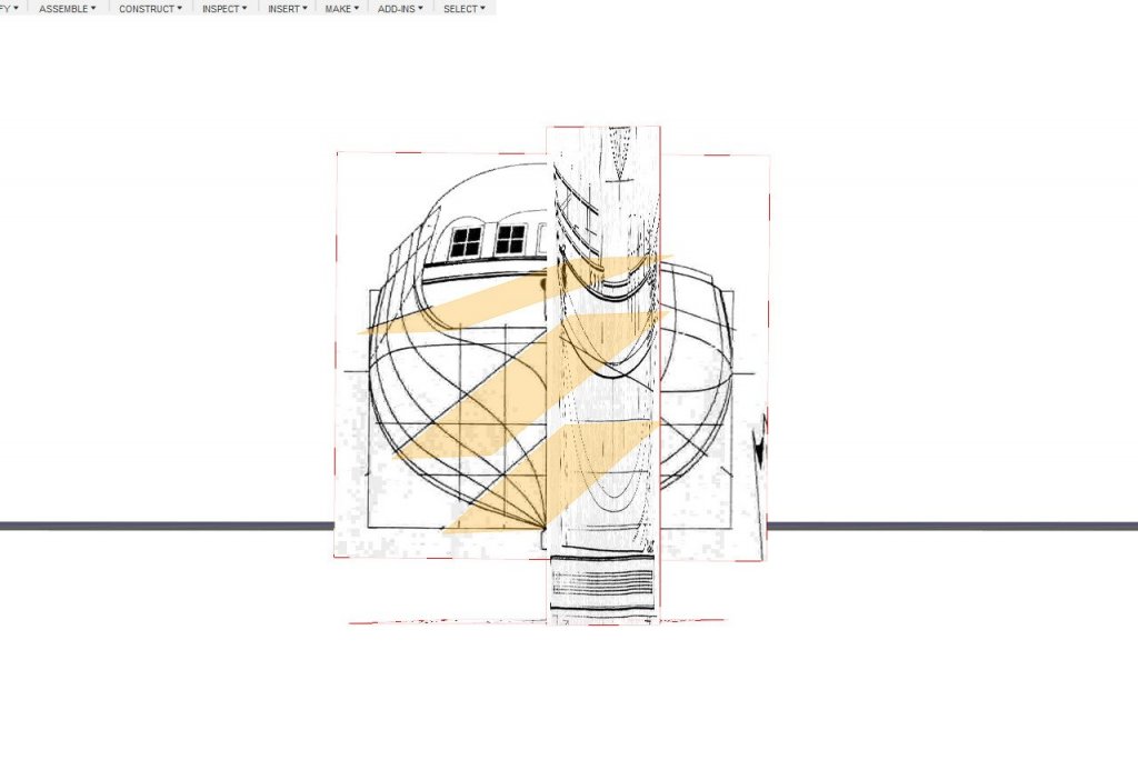
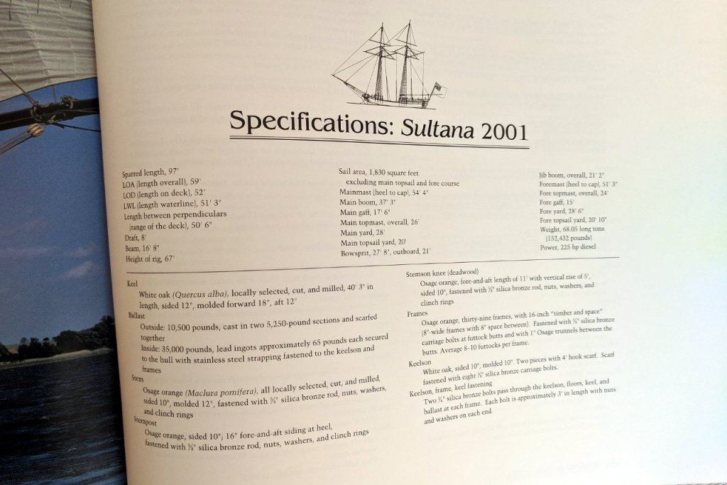
 Oh, right. I'm modeling the Sultana replica, which has a diesel engine. So I need a cutout in the rudder. After looking at some reference pictures, I tried creating the cutout, which is roughly elliptical. It didn't look quite right. Here is a screencap, cropped and flipped horizontally, from the YouTube video "Sultana Haul Out". I see what's wrong now. On the replica, the rudder has been extended back to make up for area lost to the cutout. As a result, the back edge is nearly vertical. Also, another detail is that the bottom edge of the rudder is higher than the bottom of the keel. And a little bite will need to be taken out of the sternpost. (Also interesting is that, in 2013 when this was recorded, the Sultana's hull was painted red below the water line. It was all white when launched. I don't know when the red color was added and whether or not it's still like that. I have noticed other changes in the paint job as well.) Here is the revised rudder. The Schooner Sultana book says that the prop is 32 inches in diameter. At 1:64 scale, that's 12.7mm. I checked and the cutout is large enough.
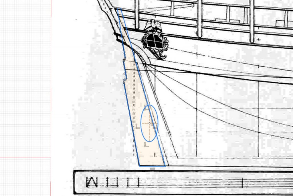
- 222 replies
-
- 4
-

-
- sultana
- model shipways
- (and 1 more)
-
I think I have things set up properly for the rabbet. Have a look at the picture below, which is a view directly from the side. There is a thin gap between the keel and false keel. My plan is to put a thin rabbet strip there. The idea is taken from Chuck's Syren practicum. Have a look at the diagram on the bottom left of page 4 to see how it's supposed to turn out. Also, I plan to cut the keel from thicker sheet than the false keel.
- 222 replies
-
- 3
-
-
- sultana
- model shipways
- (and 1 more)
-
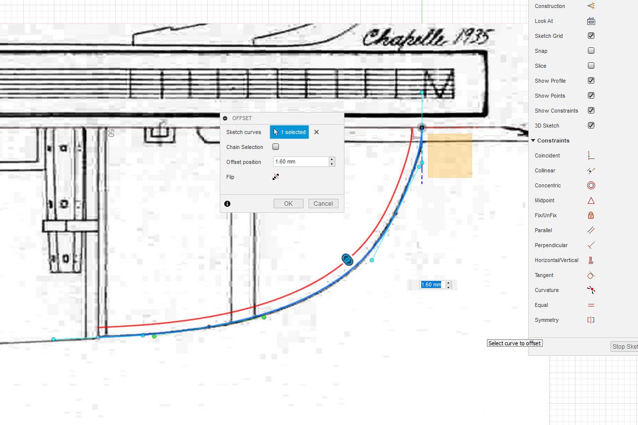
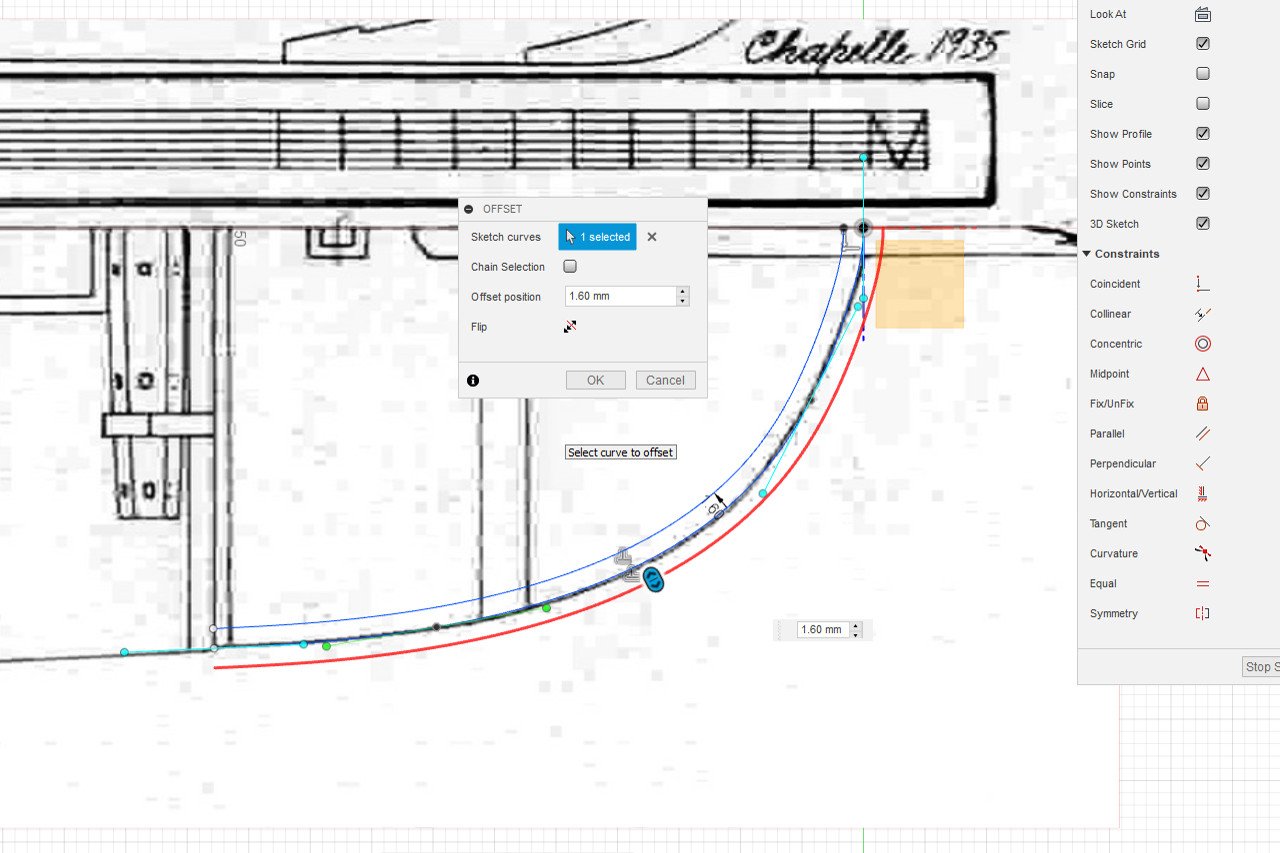
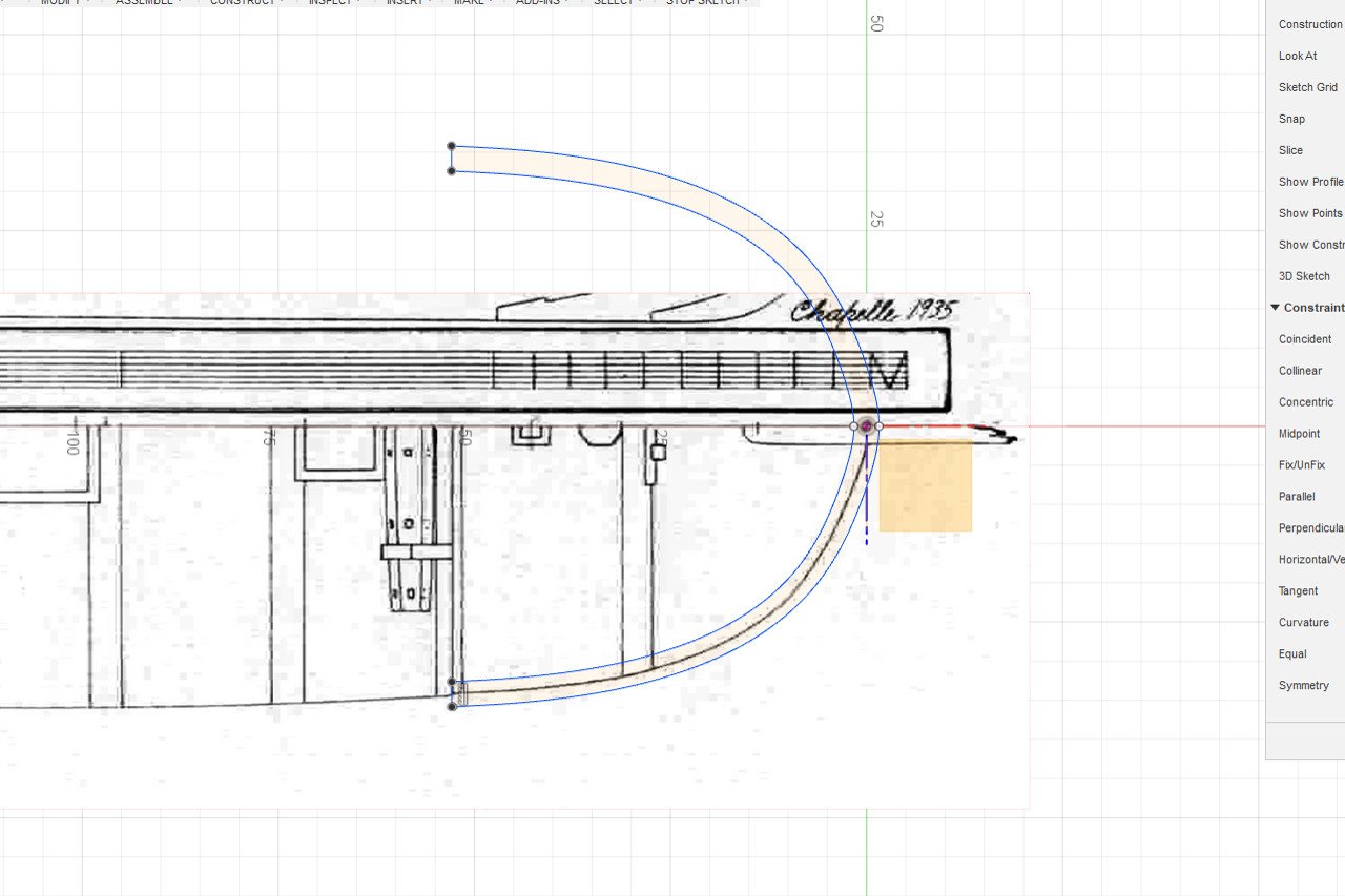
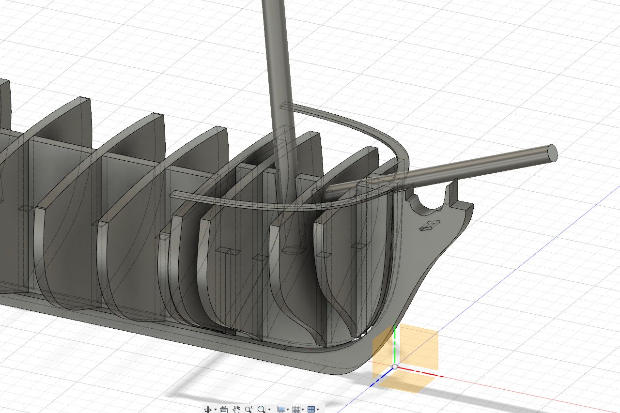
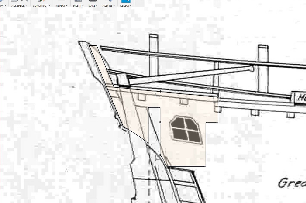
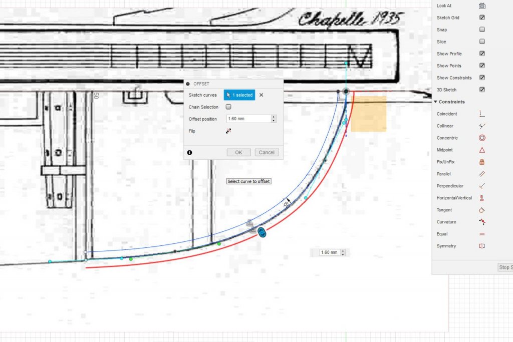
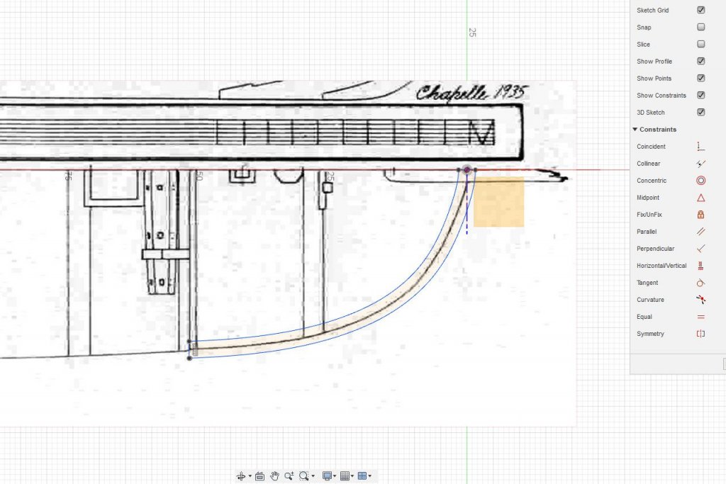
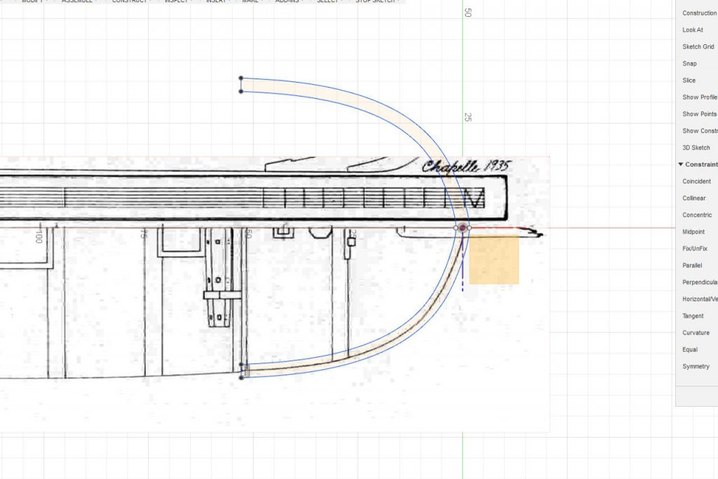
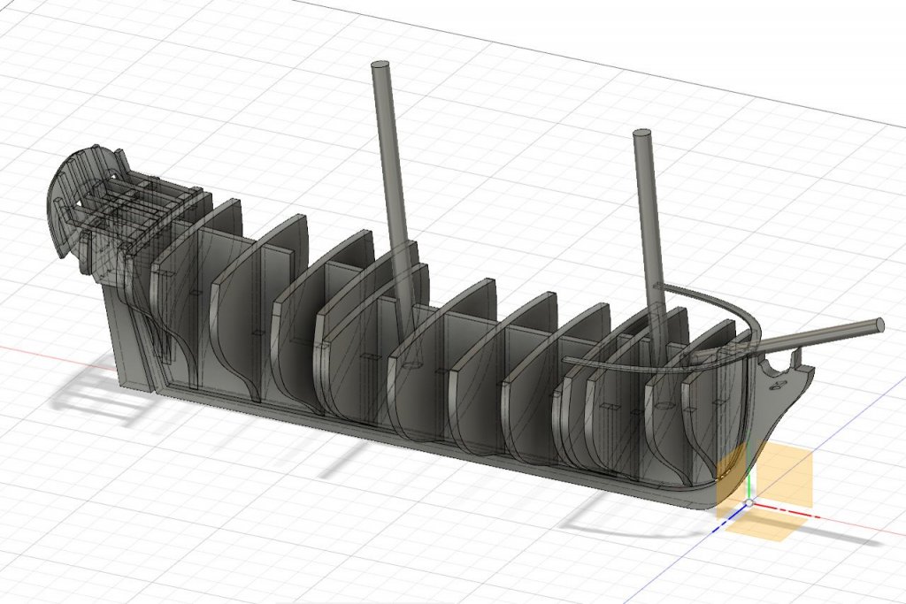
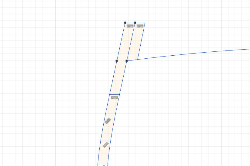
Thanks for your comments. But I don't think I'll be quitting my day job just yet. Working on the cap rail at the bow. First, a fit point spline to match the correct curve. Cap rails will be 1/8" / 3.2mm wide. I use Sketch -> Offset with an offset of 1.6mm to create the inner edge. The offset is repeated to create an edge 1.6mm in the opposite direction. The original line is removed and the shape is closed. And mirrored. Here is the piece roughly in place. The actual piece will not be flat; it will slope down as it follows the top the bulwarks. And here's a big picture of everything. There is one notable change. I decided not to include the gun stocks as part of the aft bulkhead pieces. I realized that I would have to plank around them, which seems like too much trouble. And with that, I think I have designed all the pieces that I want. Now I need to arrange them for the laser cutter. I'm still debating basswood vs. some other wood to use in the laser cutter.


- 222 replies
-
- 4
-
-
- sultana
- model shipways
- (and 1 more)
-
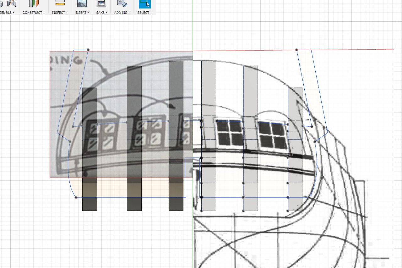
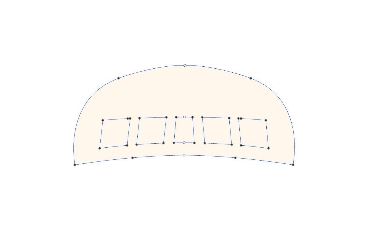
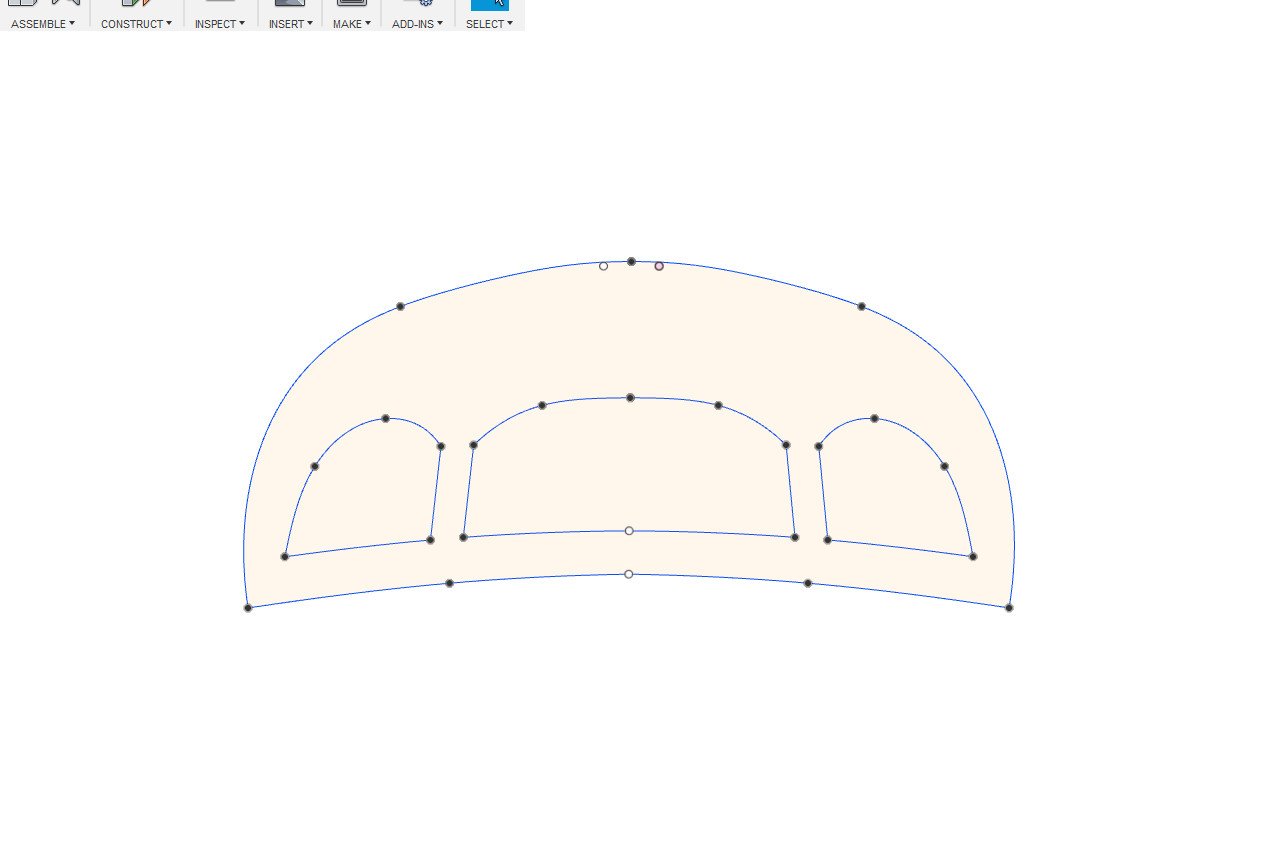
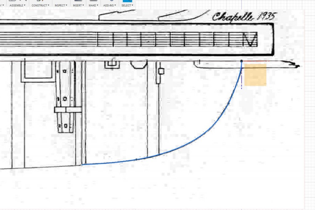
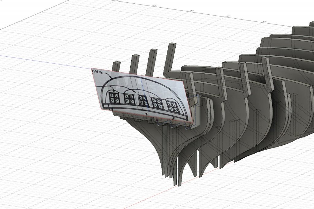
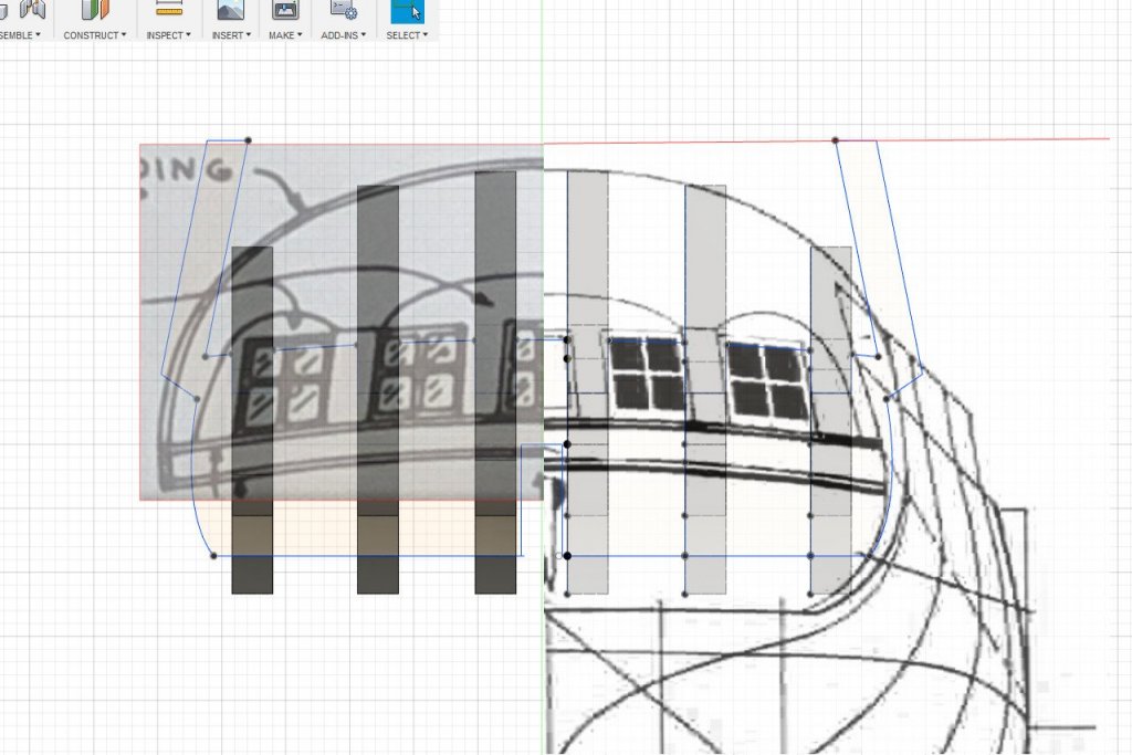
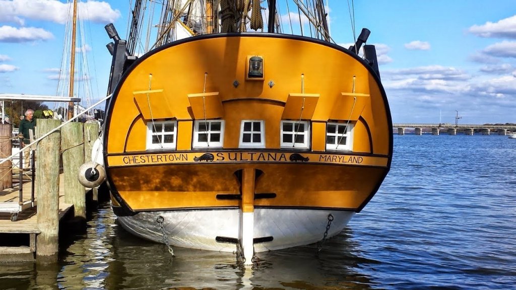
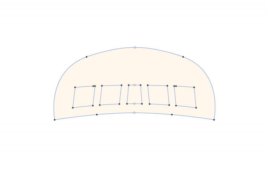
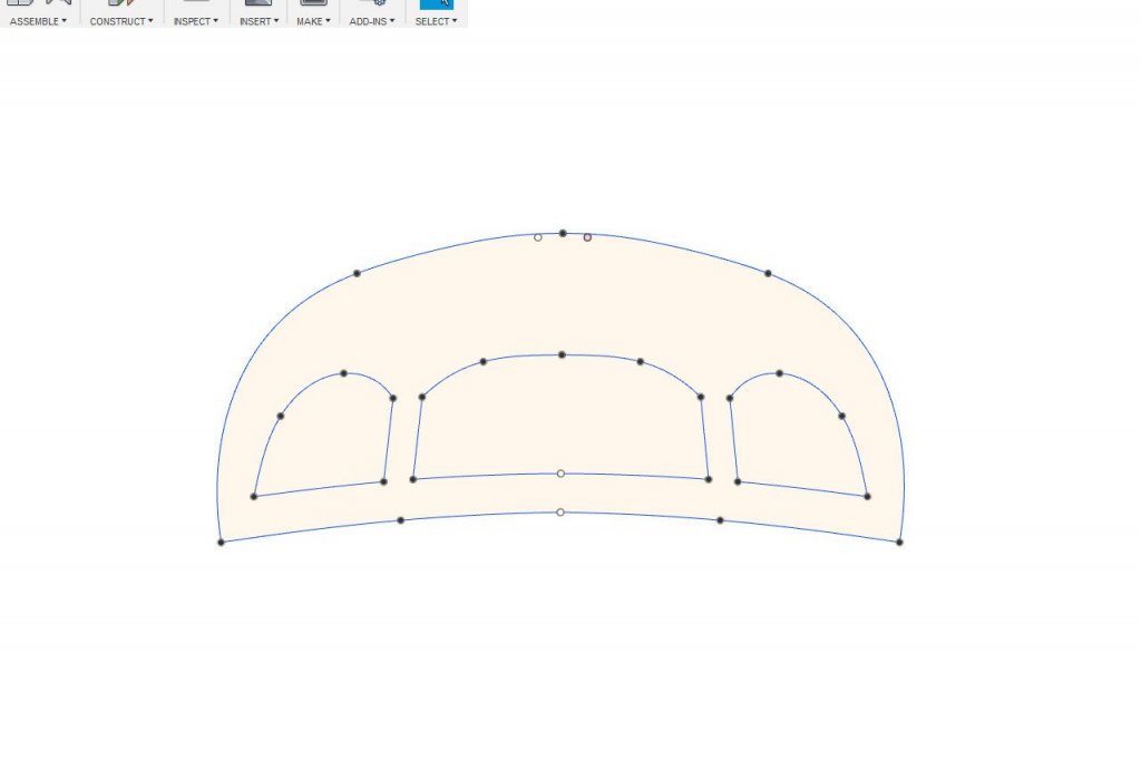
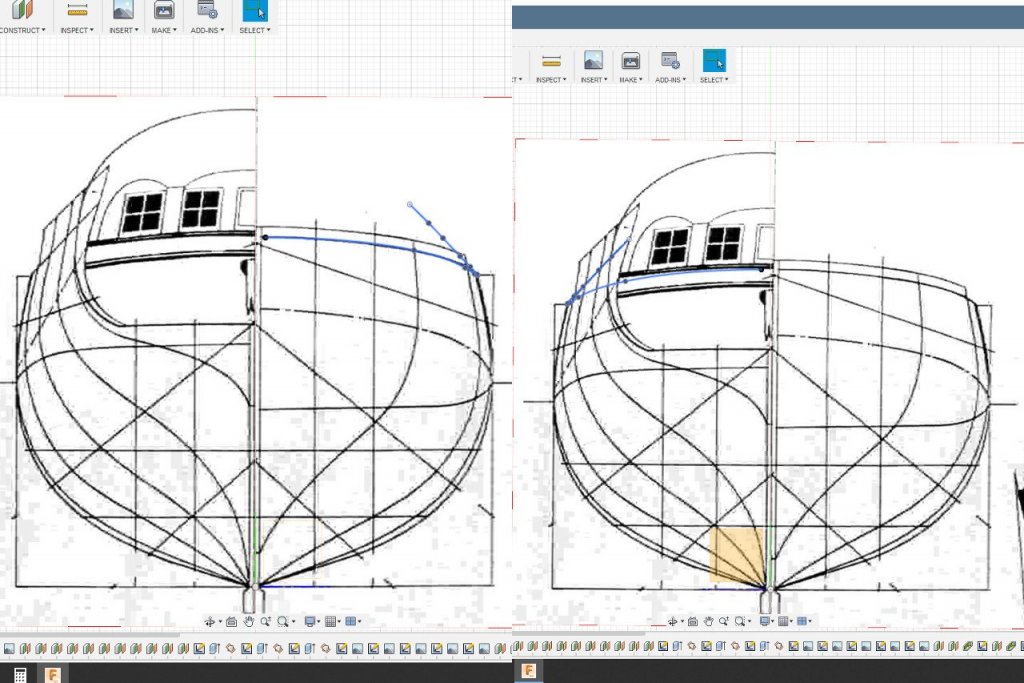
Reference marks were added to the scribe lines for each bulkheads (in the same sketches where the fairing lines are drawn). These reference marks indicate the location of the wales and the bottom of the bulwarks on each bulkhead. Next I turned to the end piece for the transom. After some careful measurement, I determined that the transom outline on the Model Shipways plans seemed to be properly sized. I scanned the image and brought it into Fusion 360. So far so good. In this image the Model Shipways transom is on the left, and the Chapelle transom on the right. The general shapes are similar, but the MS transom windows are larger and spaced further apart. Also, on the MS transom the lines for the recessed portion of the transom are higher. (There are also some symmetry issues with the MS drawing.) So what's correct? As I mentioned at the start of this build log, I will be using the Sultana replica as the standard. Fortunately, I found a good picture of the Sultana's transom at the website "829 Southdrive". Picture by the website author "Baydog". From this picture, the windows should be fairly small, and the recess line is fairly low. That makes the Chapelle drawing the closer match. Following the Chapelle transom and the reference photo, I came up with these two sketches for the two pieces. Solid parts were created in the 3D environment to see how they will look. (The real parts will be curved.)

- 222 replies
-
- 4
-
-
- sultana
- model shipways
- (and 1 more)
-
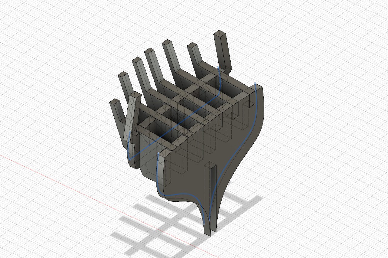
I've decided to go with the bulkheads at the bow that are perpendicular to the false keel. I have added some extra pieces at the bow. Blue lines are fairing lines that will be scribed onto the pieces Shapes of the stem, keel, sternpost, and rudder were traced from the inboard profile image. Bulkheads at the points where the deck level changes were doubled up so that there will be good surfaces where deck planks start and end. There is also a cutout now, partially obscured in this picture, for the hatchway ladder that goes down into the hull. And so here is what everything looks like at this point. Still to be done: design the transom end piece it might be nice to laser cut the cap rail at the bow add guide marks for the wales and any other useful reference marks Then it's a matter of exporting each element as a DXF and arranging them for the laser cutter. I need to decide soon whether I want to use basswood sheets or some harder wood. Because there are limitations on the width of hardwood sheets, that will affect how I can arrange the pieces for cutting.
- 222 replies
-
- 5
-
-
- sultana
- model shipways
- (and 1 more)
-
Yeah, on some of the build logs for Master Korabel kits I noticed that they use a big lateral piece to hold the other pieces, including some angled pieces. It seemed like a great idea to steal. But on this ship, it doesn't seem to gain me much. It would be more appropriate for a ship where the timberheads form stanchions for tall bulwarks with gun ports. On the Sultana, the bulwarks are really short. So I think in the end I'll be going with conventional bulkheads all perpendicular to the false keel.
- 222 replies
-
- 3
-
-
- sultana
- model shipways
- (and 1 more)
-
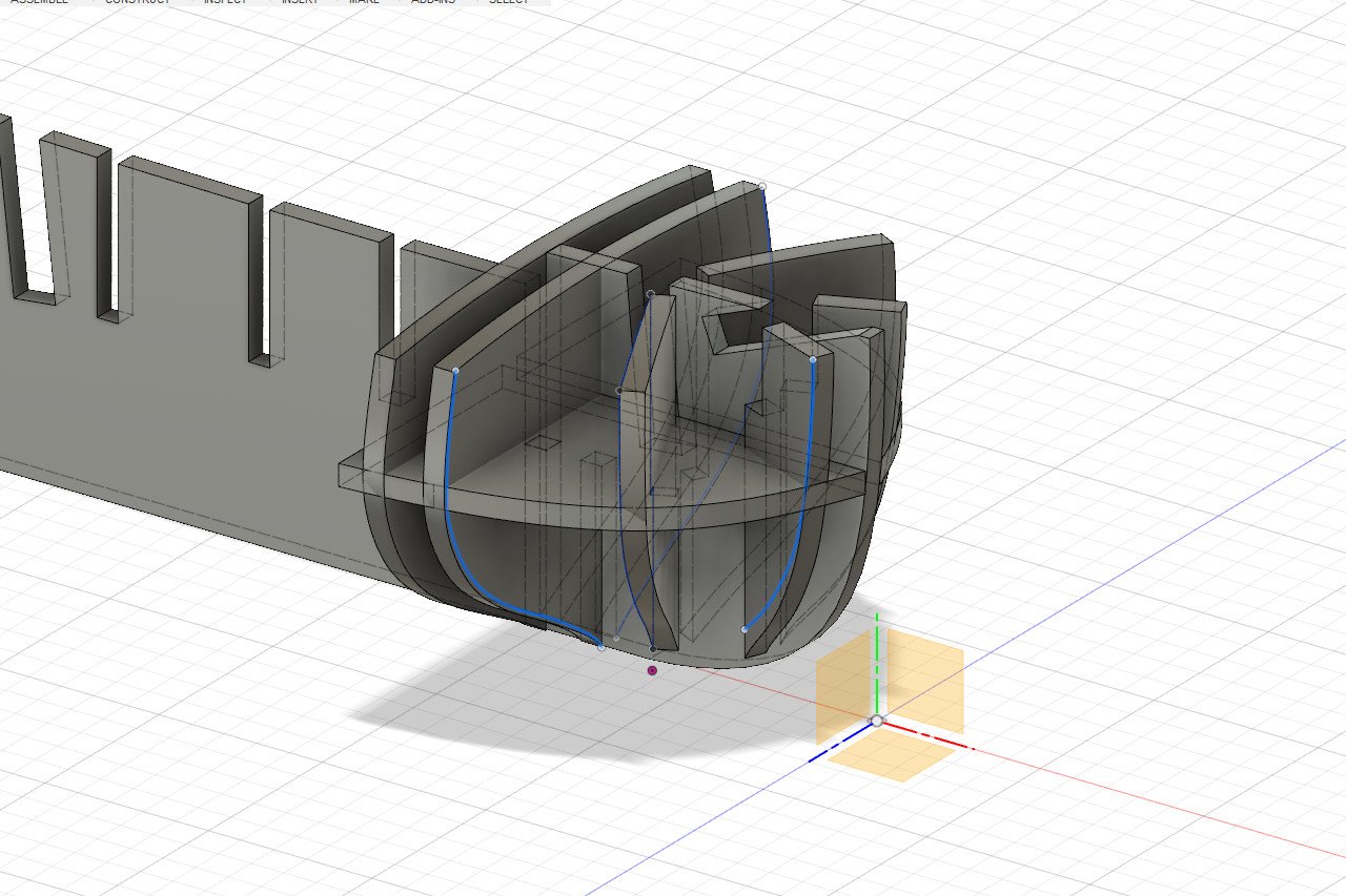
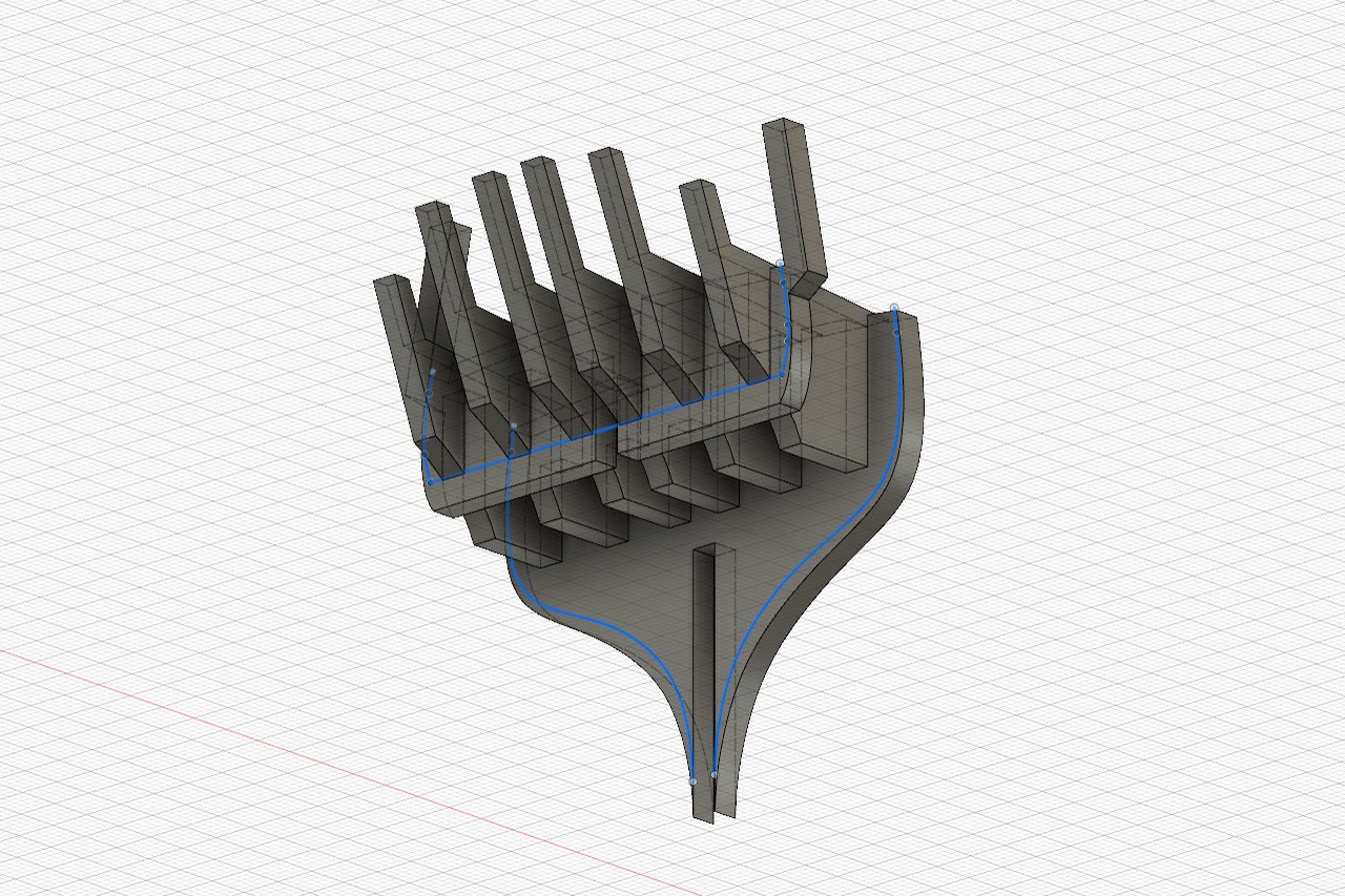
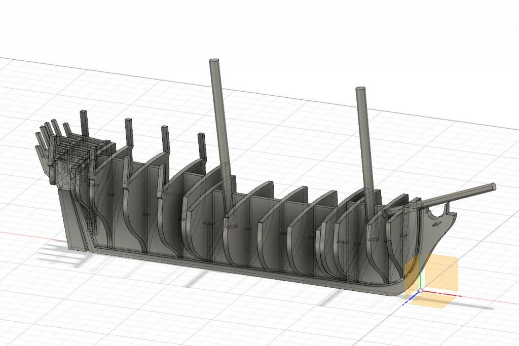
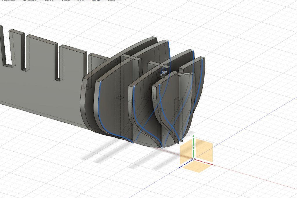
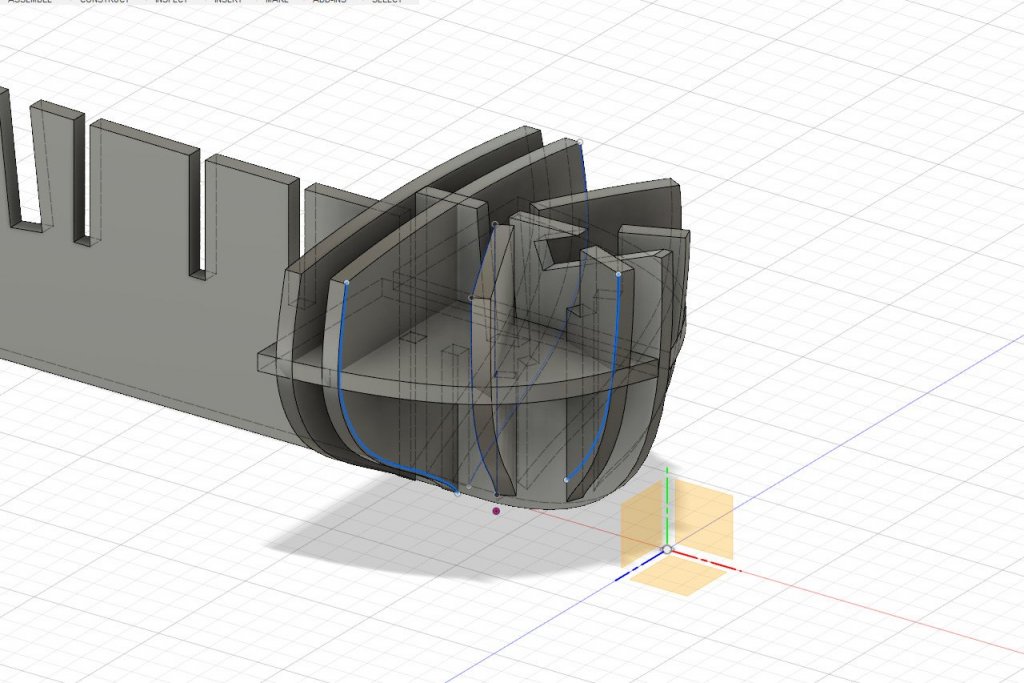
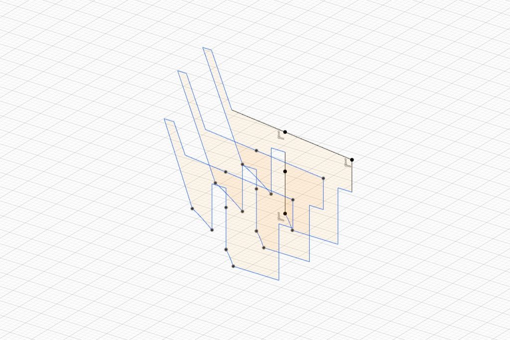
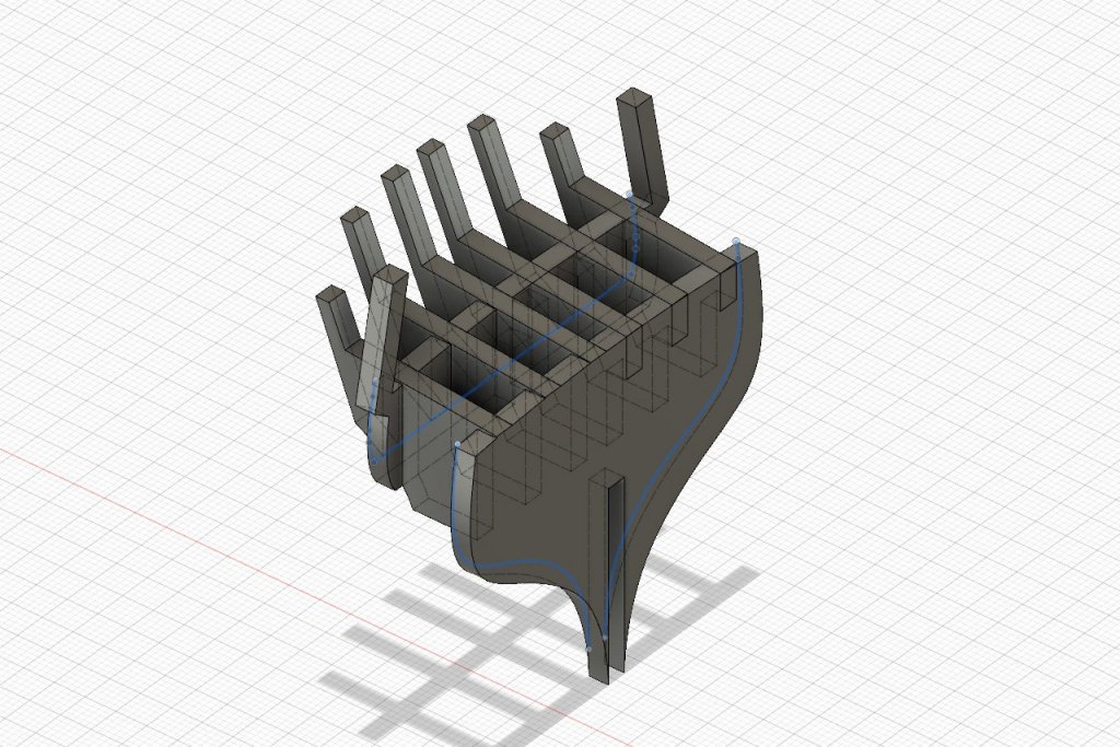
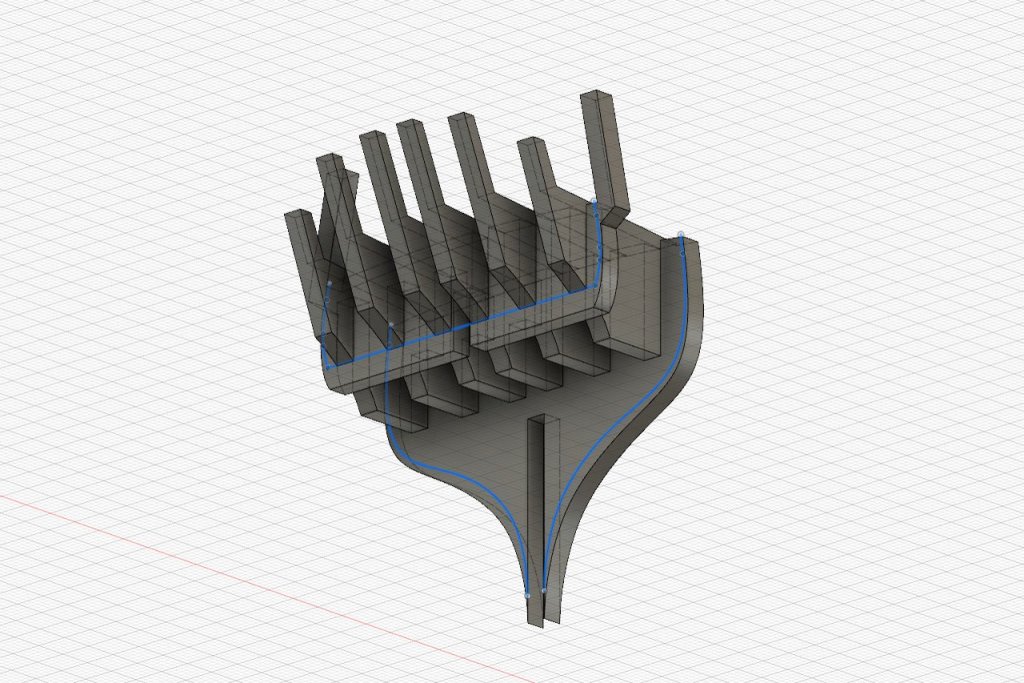
I've been trying different ideas for how to deal with the bow. The first option is fairly straightforward. There are holes in the bulkheads for the bowsprit. Blue lines are fairing lines that will be scribed on the parts. Option two is a bit more radical. There are pieces at an angle somewhat analogous to cant frames. Horizontal pieces matching the curve of the bow will hold them in place. It looks cool, but I don't know if there is any advantage to it.
- 222 replies
-
- 4
-
-
- sultana
- model shipways
- (and 1 more)
-
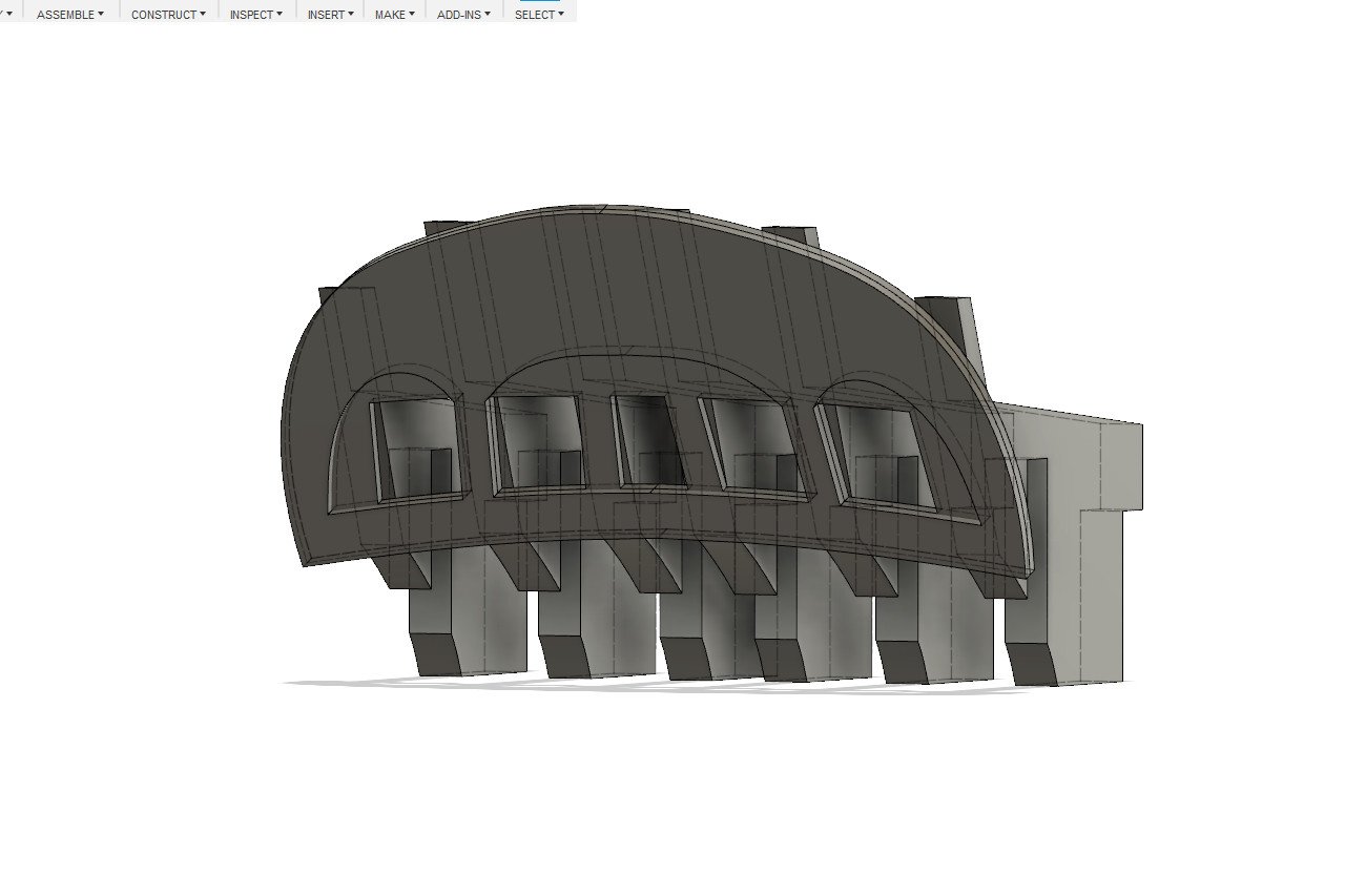
Working on the transom this time. My goals include creating a strong surface that the end transom piece can be attached to. Also, I wanted to ensure that there is some open space behind the transom windows. Here is in innermost piece. And the next two pieces. And some pictures of how the transom pieces fit together with the aft bulkhead pieces. Blue lines are the fairing lines that will be scribed on the pieces. Next, as I have been gently reminded, I have to figure out how to deal with the bow of the ship.

- 222 replies
-
- 4
-
-
- sultana
- model shipways
- (and 1 more)
-
Ha. No, let me see if I can make something usable first. At the end of all of this, if there's interest, maybe I'll post the DXF files for others to use.
-
You're correct, Lou. I think you overlooked the part near the end of my last update where I mentioned that bulkheads near the bow still need to be done. My last picture is just showing the current state of the design, not the final one.
- 222 replies
-
- 1
-
-
- sultana
- model shipways
- (and 1 more)
-
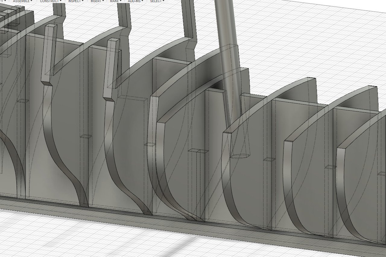
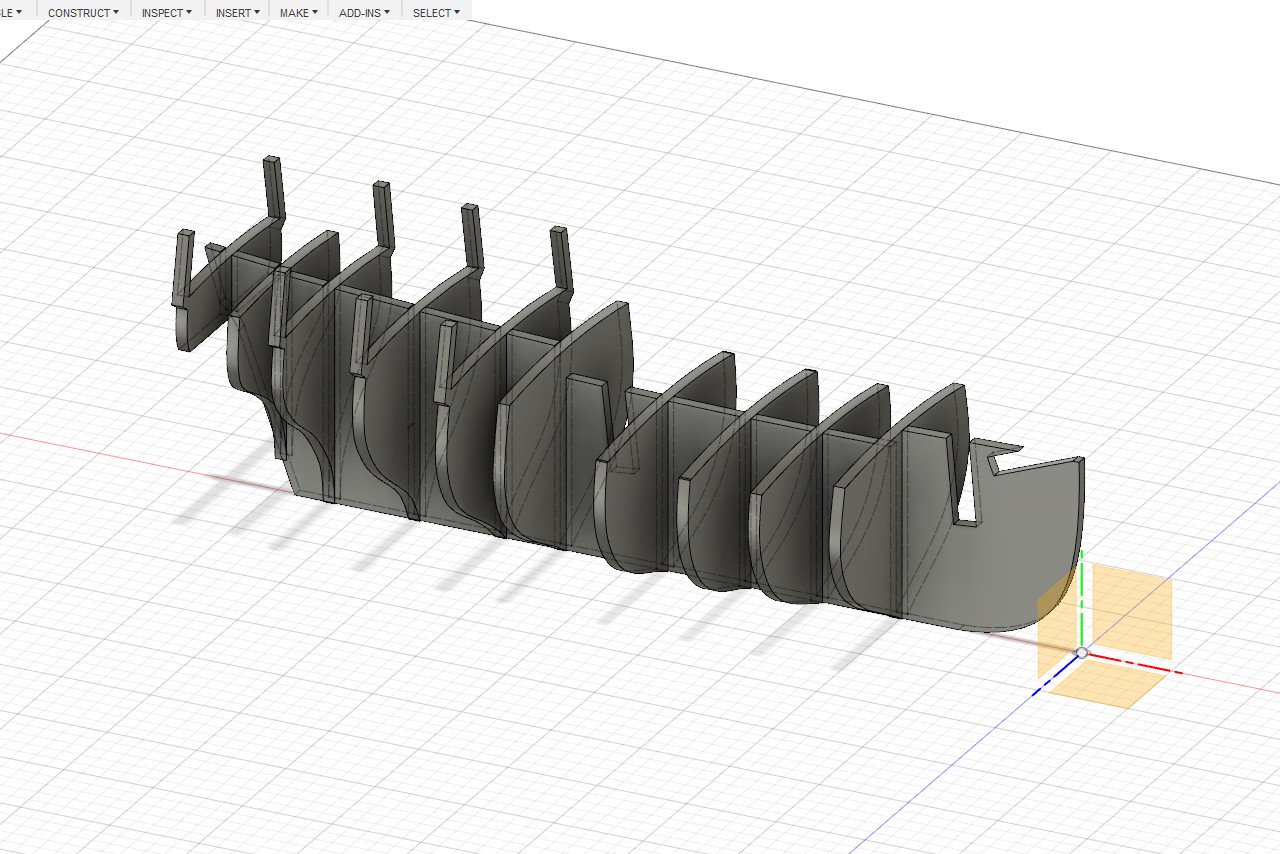
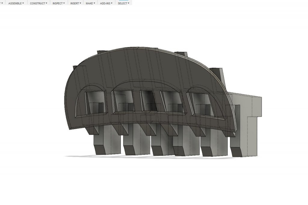
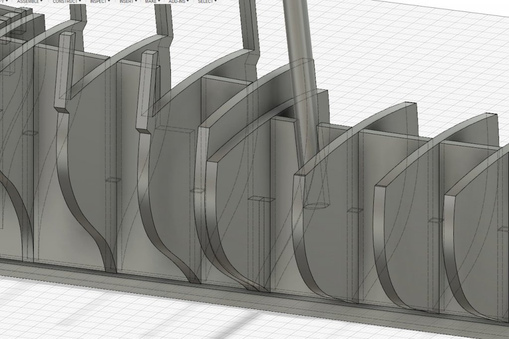
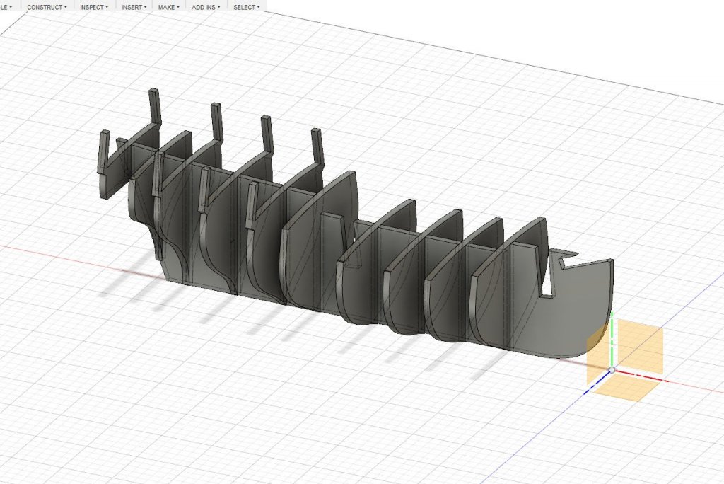
Several bulkheads were added at the center of the ship. Because little to no fairing will be required, no fairing lines were identified for these bulkheads. And here's another bulkhead in the aft part of the ship. But maybe there is an opportunity here. If the bulkhead is positioned appropriately, then I can do this... And that takes care of making the swivel gun stocks. The same is done for the other locations with swivel gun stocks. And just to get an idea of what the final product will look like, I thickened the bulkhead templates to the appropriate thickness. This is what it looks like so far. I still need to work on the transom and bulkheads near the bow.


- 222 replies
-
- 5
-
-
- sultana
- model shipways
- (and 1 more)
-
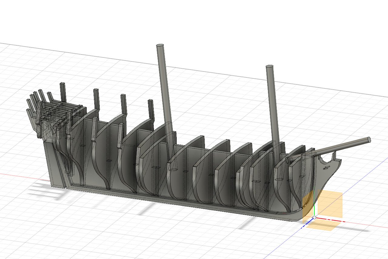
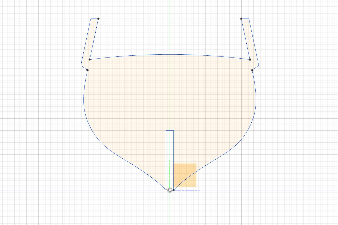
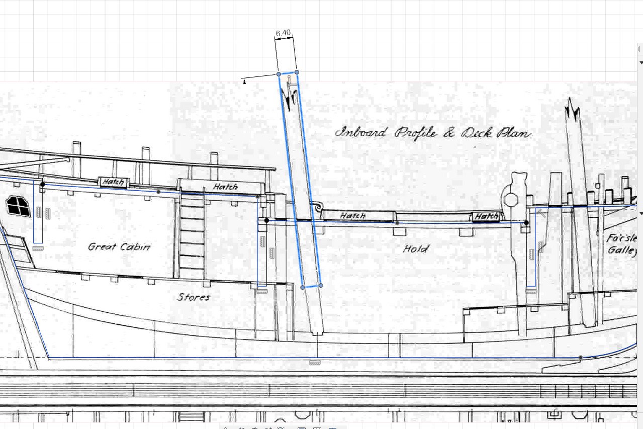
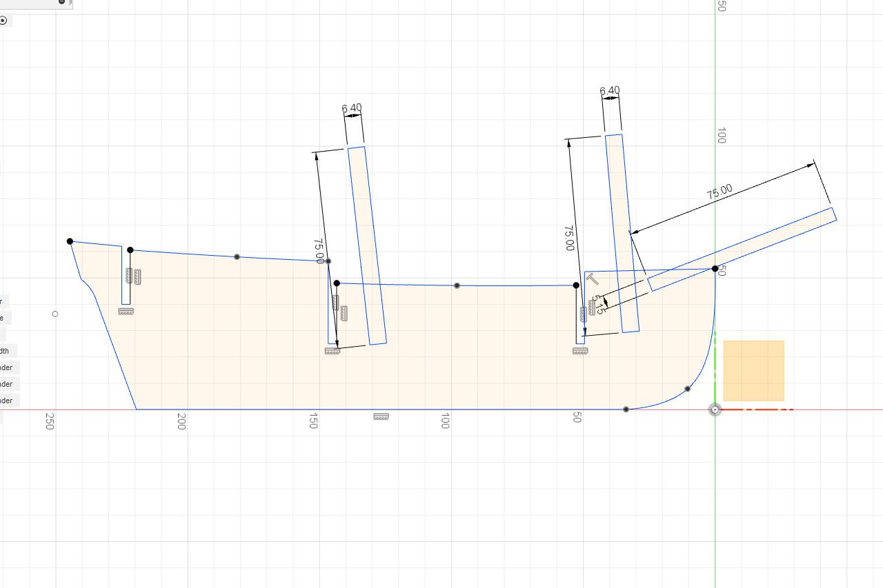
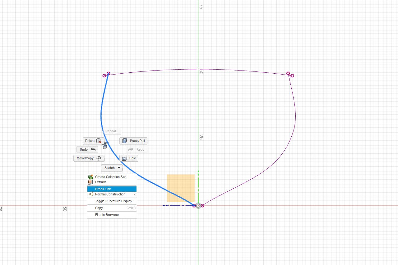
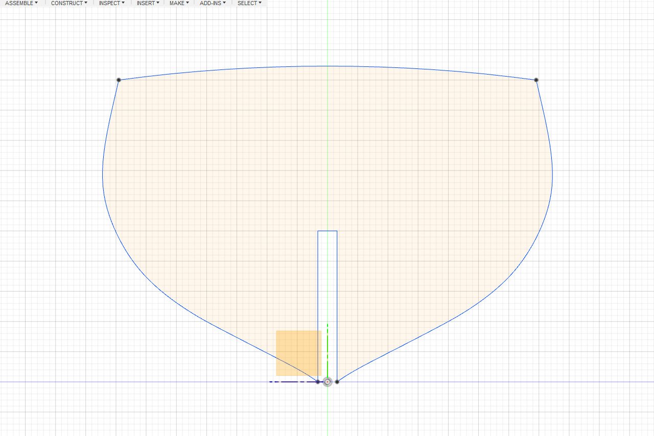
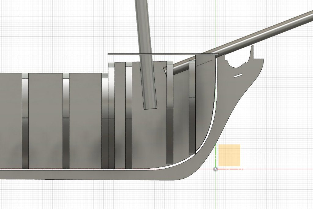
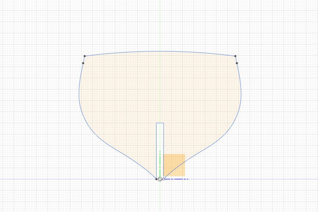
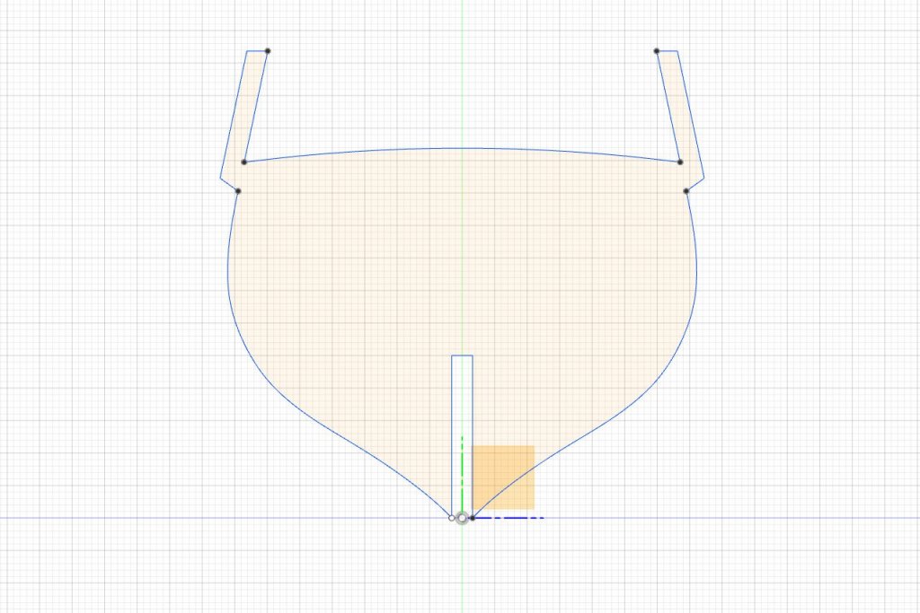
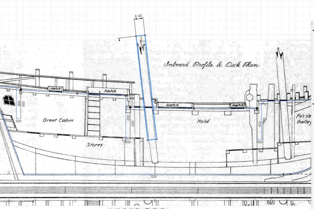
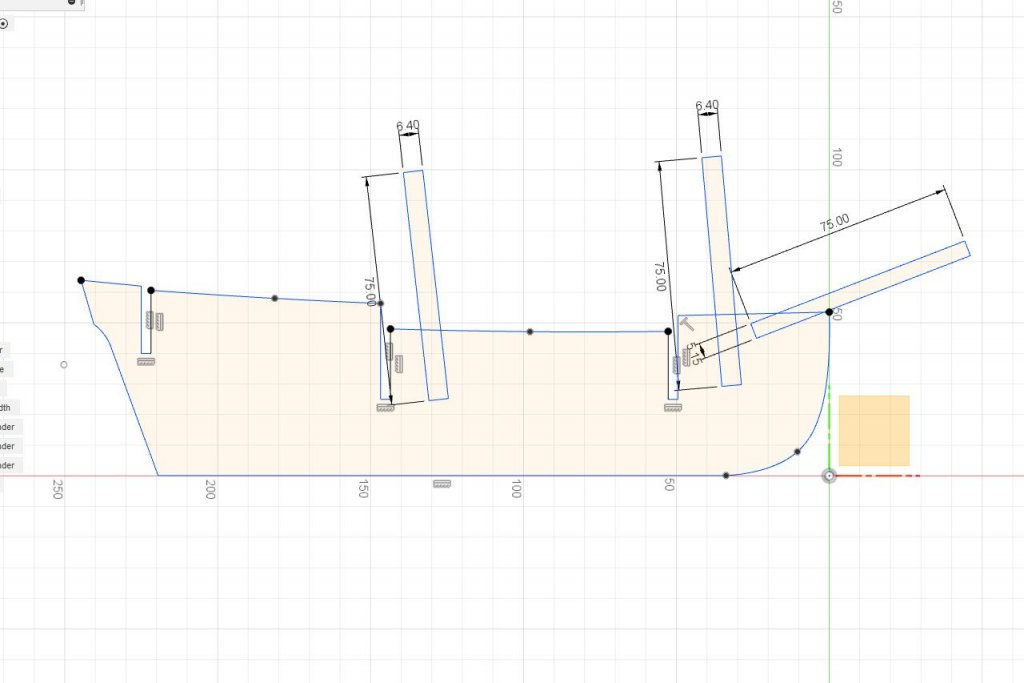
Before I add any more bulkheads, I think it's a good time to cut out the notches for the masts and bowsprit. The kit-supplied dowels are 6.4mm in diameter for the masts and 5.15mm in diameter for the bowsprit. Tapering will be required above the deck, but I'm happy to leave them at full diameter within the hull. I edit the sketch for the false keel. Rectangles are added with a width equal to the diameter of the dowel, then rotated and moved in position to line up with the masts on the inboard profile image. A similar procedure is followed for the foremast and bowsprit. Finally, the Sketch -> Trim tool is used to get rid of the lines that aren't needed. I hope that little pointy bit at the front won't break.
- 222 replies
-
- 4
-
-
- sultana
- model shipways
- (and 1 more)
-
Yes, that's something I hope to do. Probably not. The bulwarks are very short -- just a few inches above the deck level in some places. I think I'll do things like in the practicum: end the hull planking just below the level of the deck, then fit a strip for the bulwarks above it, with another strip on the inside.
- 222 replies
-
- 2
-
-
- sultana
- model shipways
- (and 1 more)
-
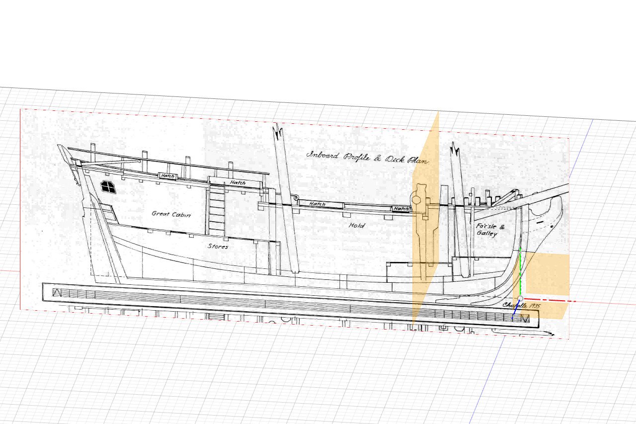
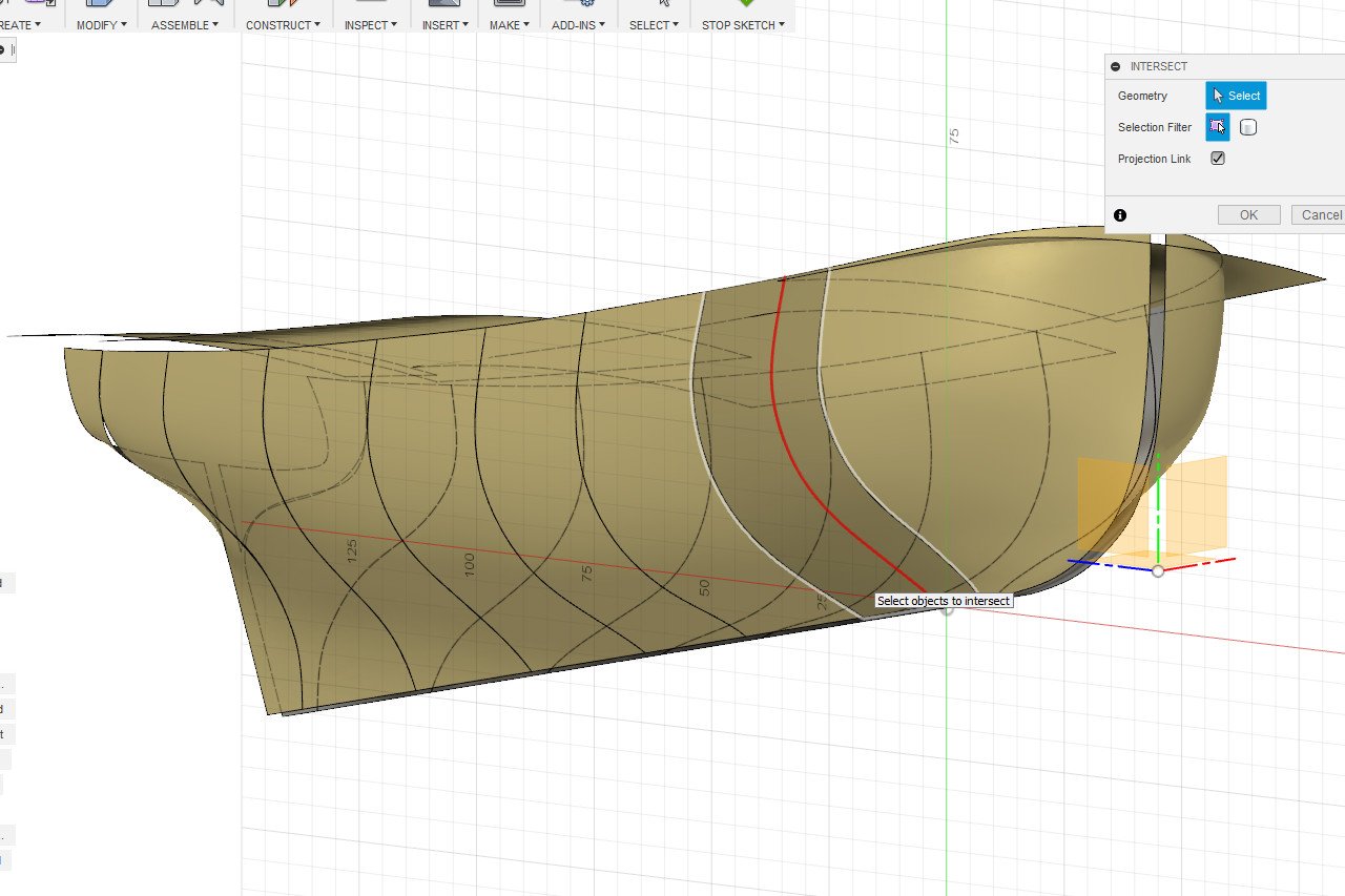
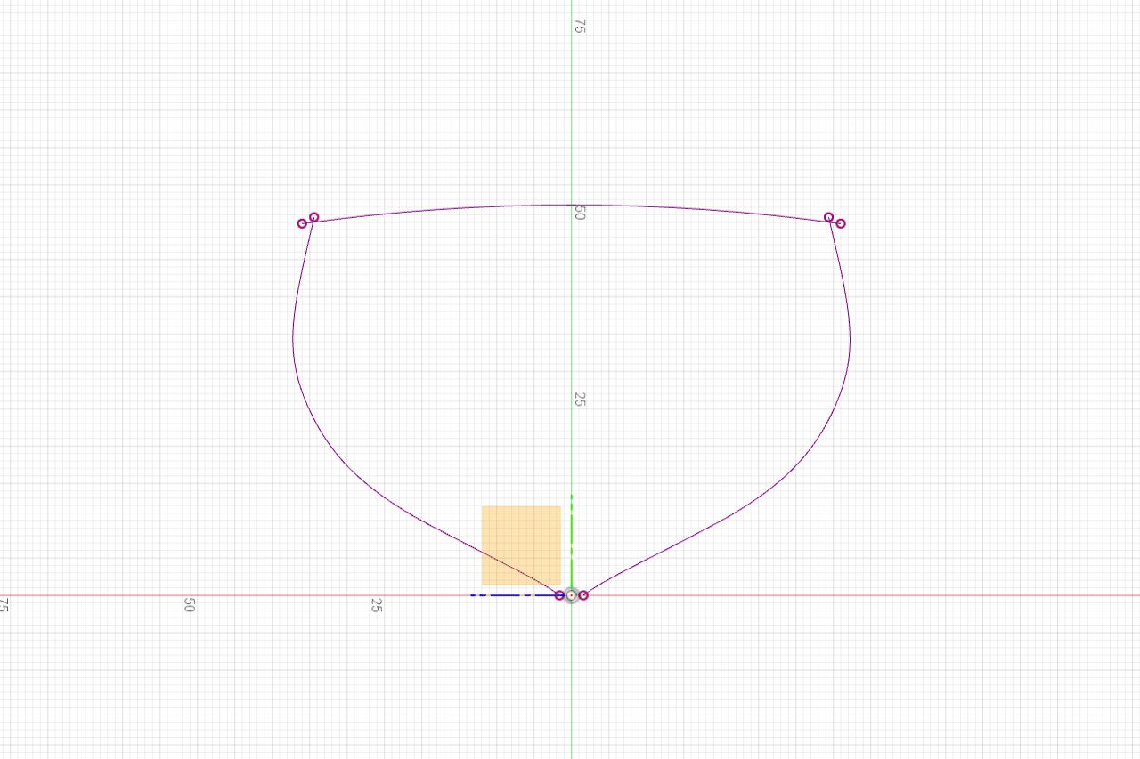
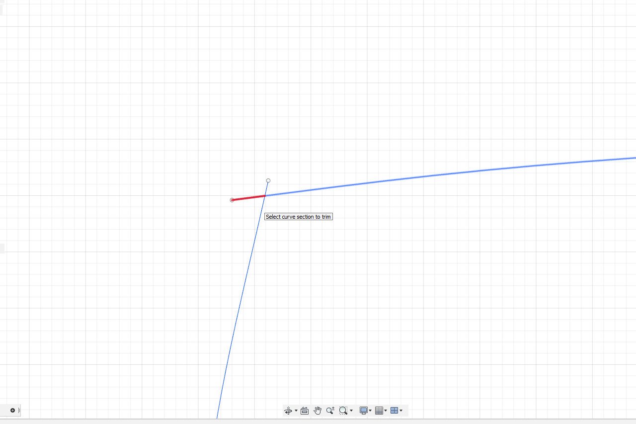
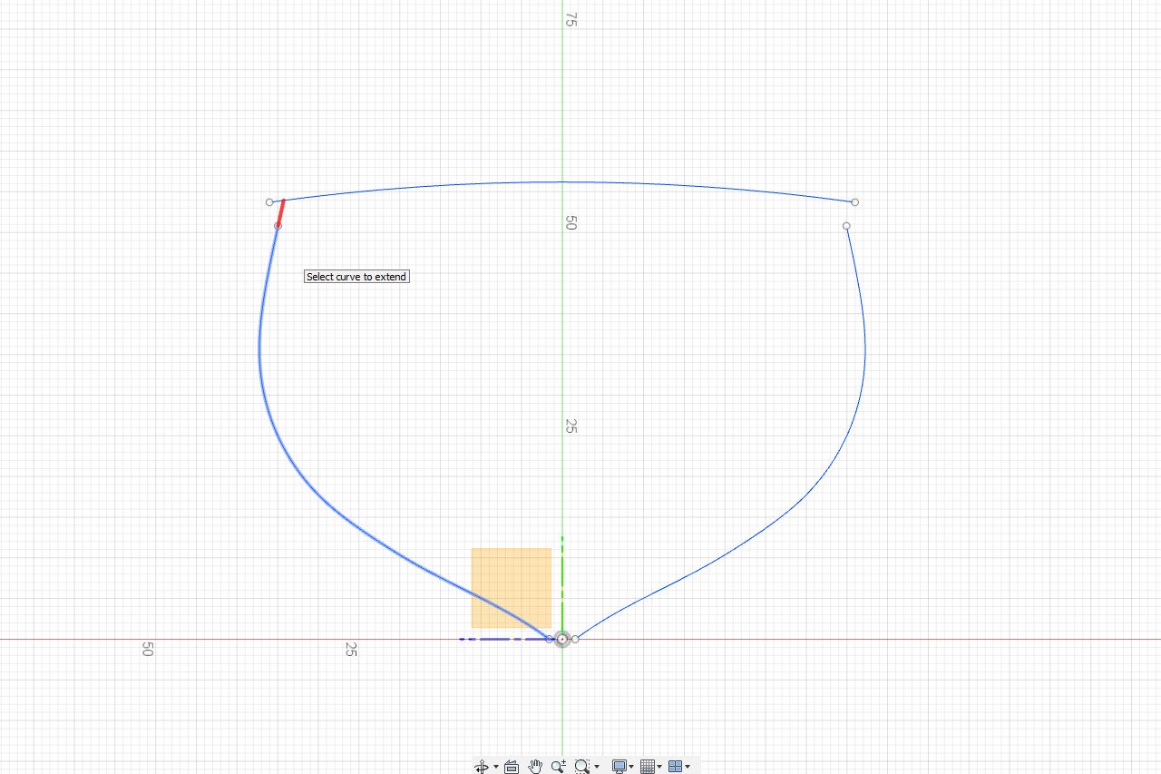
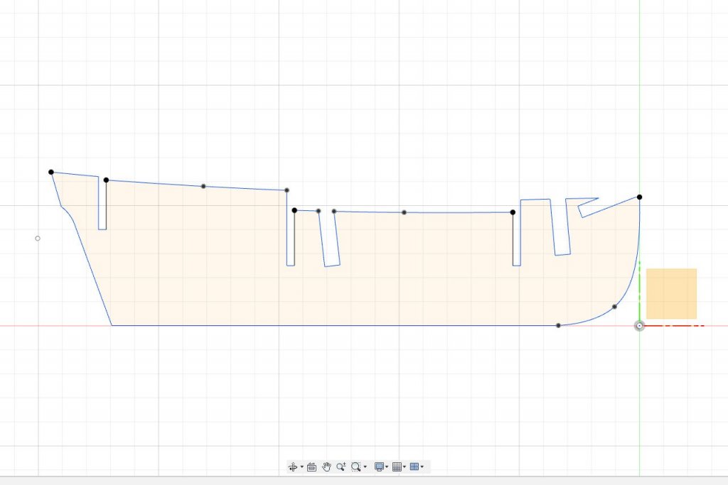
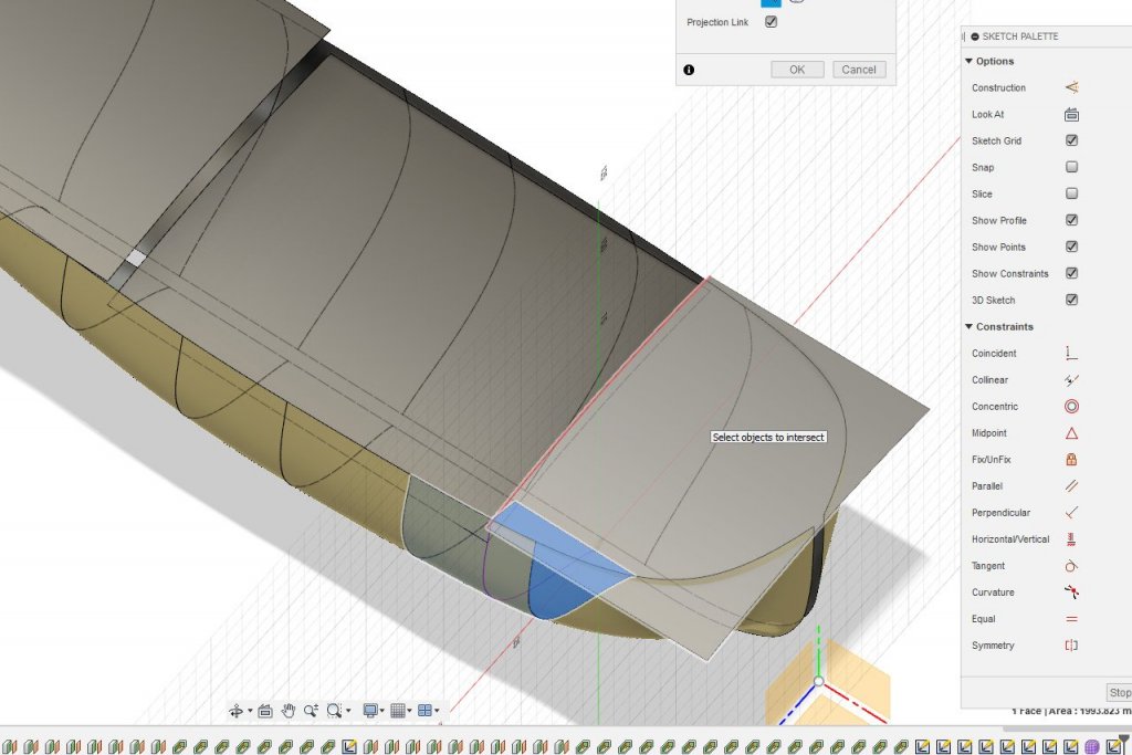
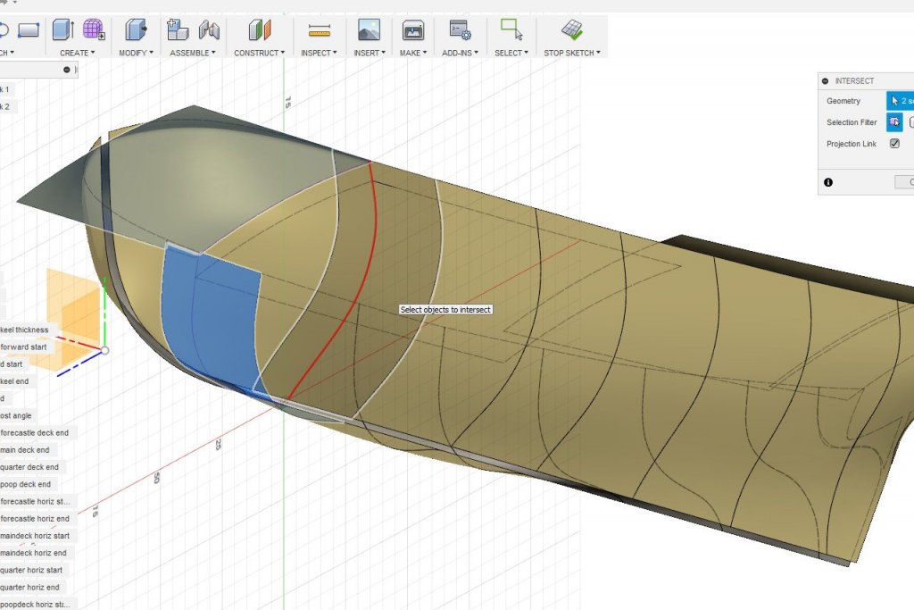
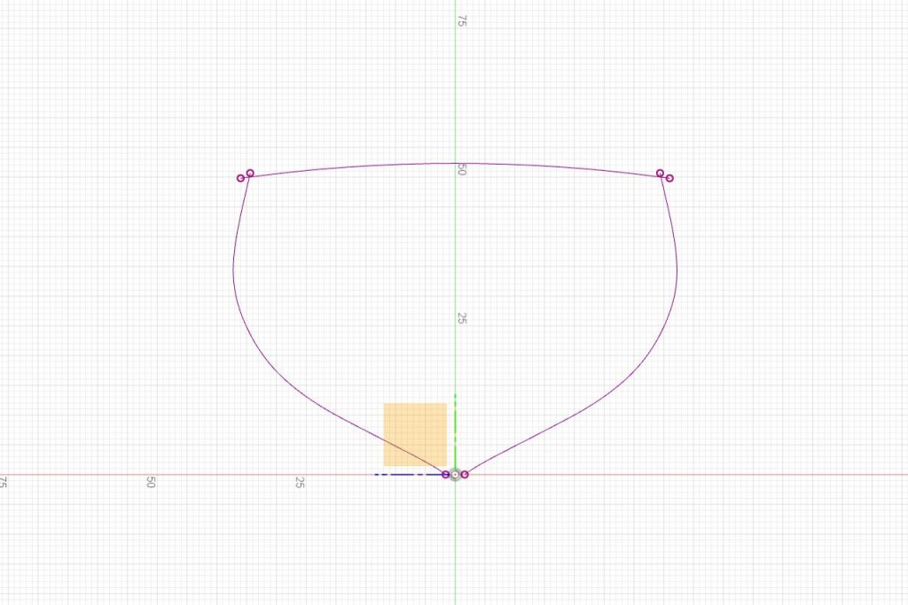
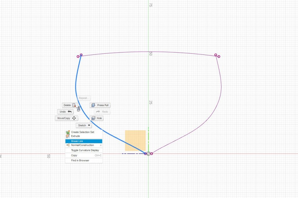
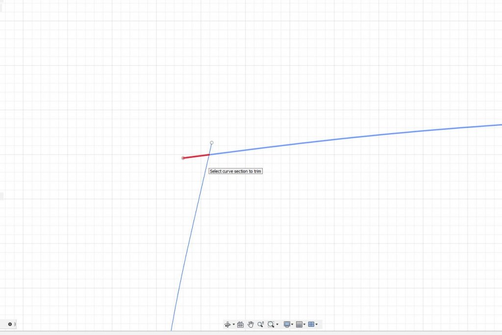
Finally I will start to find the shapes for some bulkheads. I know that I will want bulkheads at the three points where the deck level changes, so those seem like good ones to start with. I start by making the inboard profile image visible, since it shows the internal structure. Via the construction menu, I create an offset plane at the point where the forecastle deck drops down to the main deck. It's 52.7 mm back from the forward perpendicular. Next I make the hull and deck surfaces visible. I select the offset plane and go to Sketch -> Project/Include -> Intersect. As I move my mouse pointer over the surfaces, anywhere the offset plane intersects with a surface, the intersection curve displays as a red line. I'll click to select the first intersection curve. And the one across the deck. And finally the one on the other side of the hull. When I click Ok the three curves are saved as a new sketch. There is some overlap where the deck and hull lines meet. To edit the sketch any further, I have to break the link between the intersection curves and the surfaces. I select a curve, then right click and select Break Link. This is repeated for each curve. The curves change from purple to blue. Now I go to Sketch -> Trim. When trim is active, segments of lines in a sketch that can be trimmed will turn red when the mouse pointer is over them. I trim off all the overhangs. And I add a notch 25mm above the baseline. The first bulkhead is complete. I can right click on the sketch, choose Export to DXF, and import the shape into laser cutter software. Of course, I need to add a matching notch to the false keel. I would also like to add fairing lines to each piece. The procedure is the same, but I don't need to include the intersection with the deck surface, and there is no notch. For the other bulkheads at places where the deck level changes, I follow the same procedure. For the second bulkhead, the hull lines don't quite reach the deck curve. In this case, I first use Sketch -> Extend to extend the lines, then use Trim to trim any overhang. I edit the false keel sketch and add notches at the appropriate locations for the three bulkheads I've created so far. And here's a view of all the sketches defined in this session. All of these will be exported for use on the laser cutter.


- 222 replies
-
- 5
-
-
- sultana
- model shipways
- (and 1 more)
-
My goal is to produce templates for laser cutting. Hopefully it will be more clear in my next update.
-
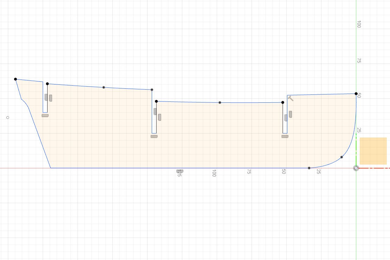
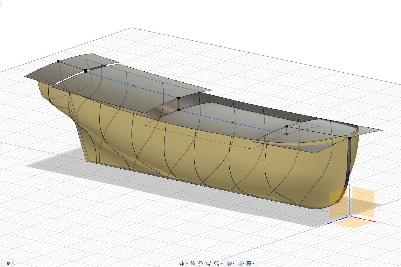
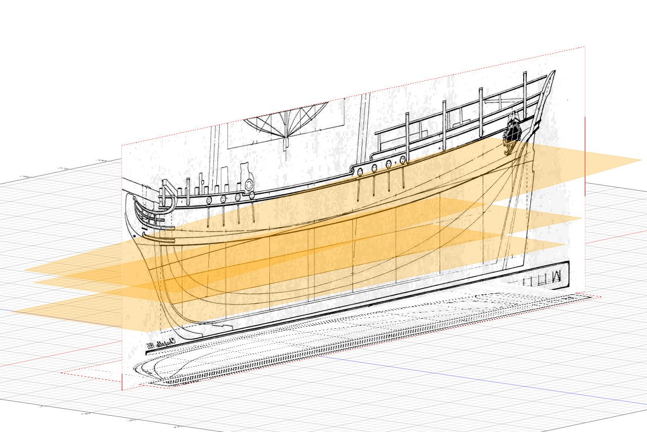
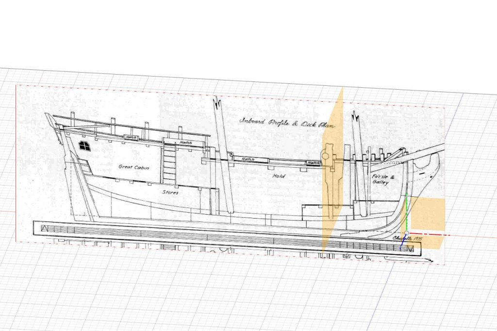
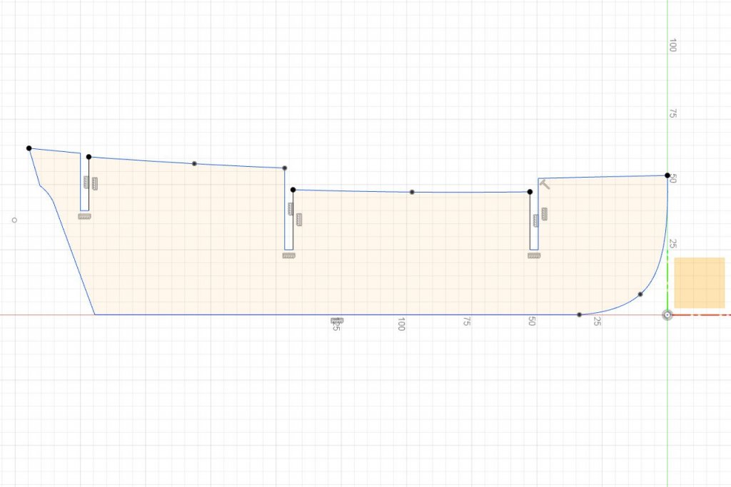
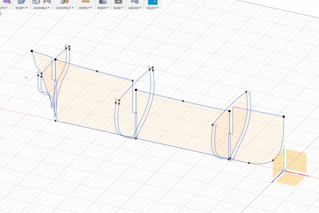
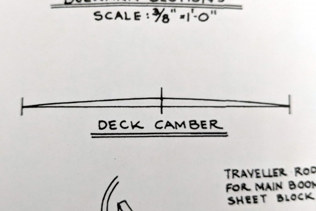
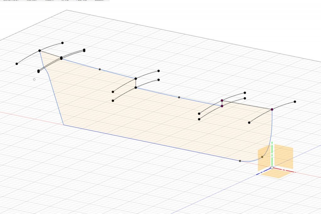
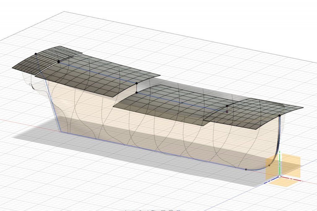
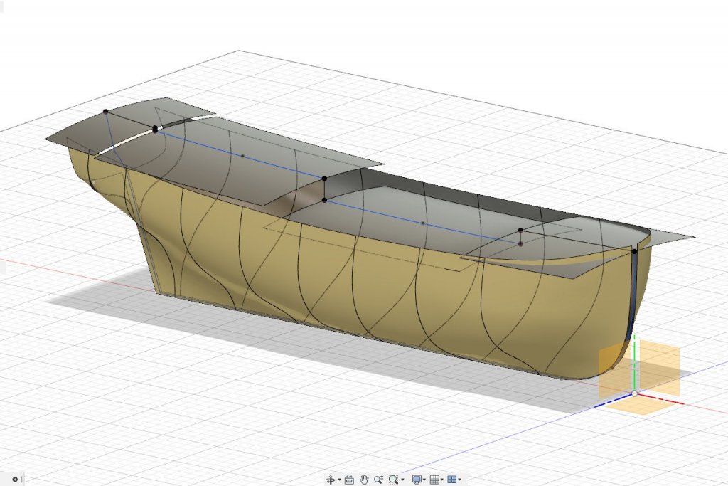
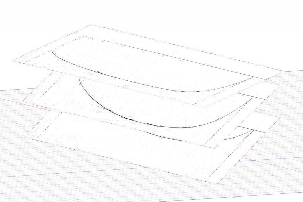
The next thing I need to figure out is the exact placement of the decks and the deck camber. I bring up the inboard profile image. Starting a sketch in the centerline plane, I trace the lines along the underside of the planking on each deck. The lines for the two innermost decks (main deck? and quarter deck?) are very slightly curved. The other two are just straight lines. The sketch continues alone the rabbet and back to the start. I'll be using this sketch for the false keel. Notches for bulkheads will be added to it later. The deck camber isn't obvious from the Chapelle plans. On the Model Shipways plans, there is a diagram showing an arc over a span of 72mm with the highest point of the arc at 2.5mm. I assume this is the camber at the widest part of the deck, but can be applied overall. Applying those measurements, I create arcs on the 3D model passing through the start and end points of each deck. Surfaces are lofted across the arcs. For the two larger deck sections, the line of the deck along the centerline is used as a rail, because it's curved. That gives those deck sections a very slight saddle shape. (This picture makes it look like I'm creating a solar-powered ship. 🙂) Here are all the surfaces to this point.

- 222 replies
-
- 6
-
-
- sultana
- model shipways
- (and 1 more)
-
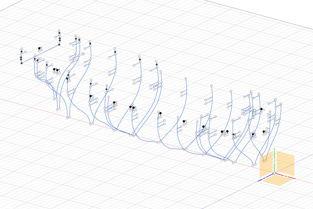
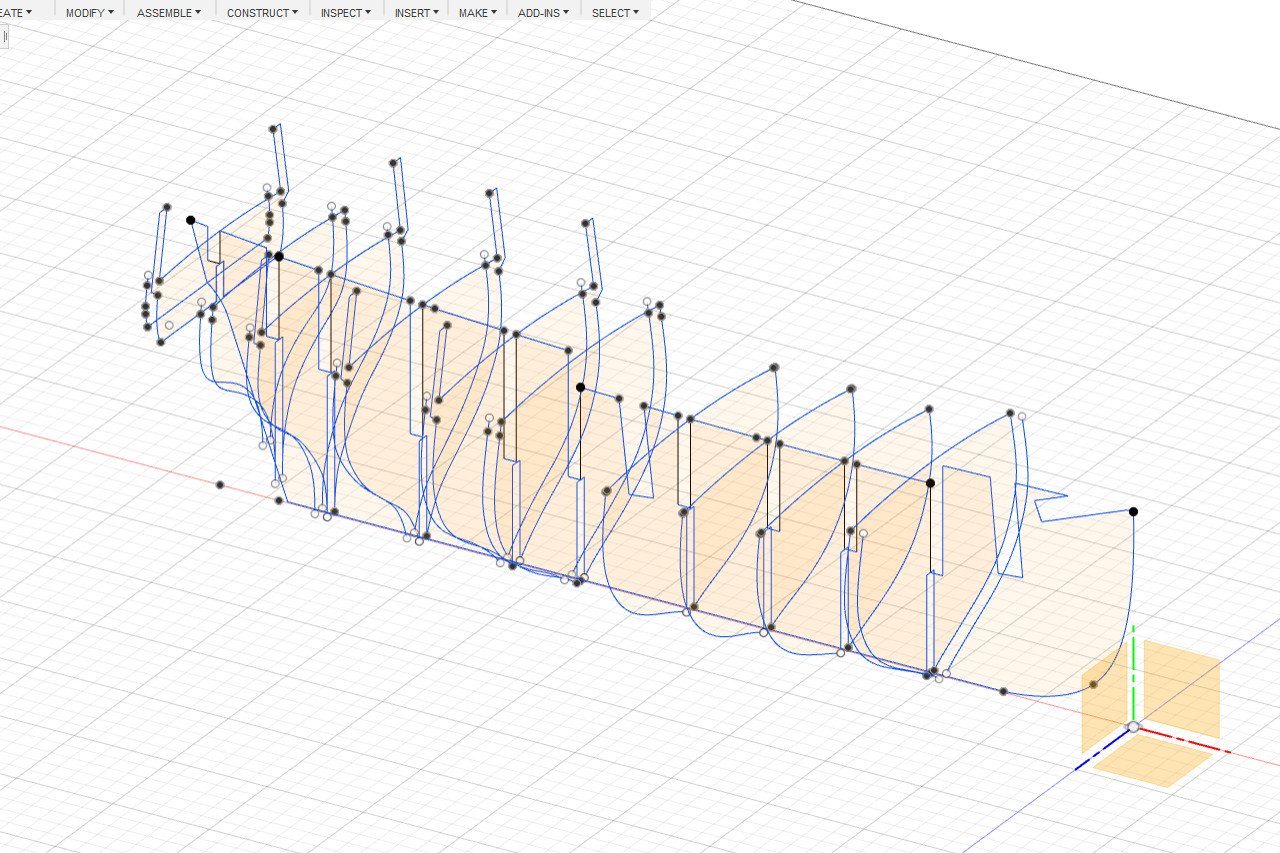
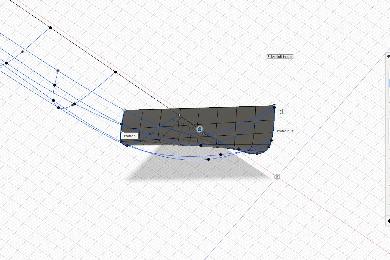
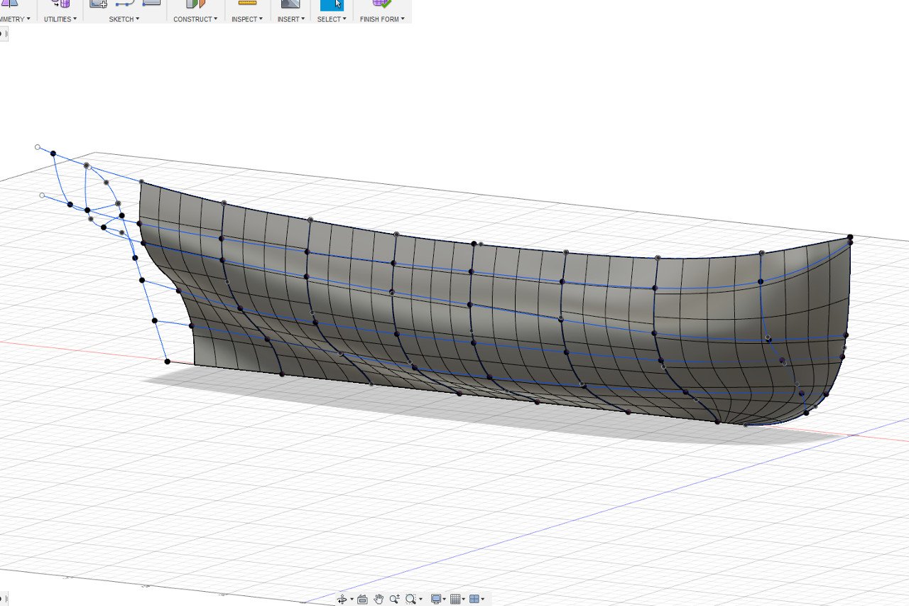
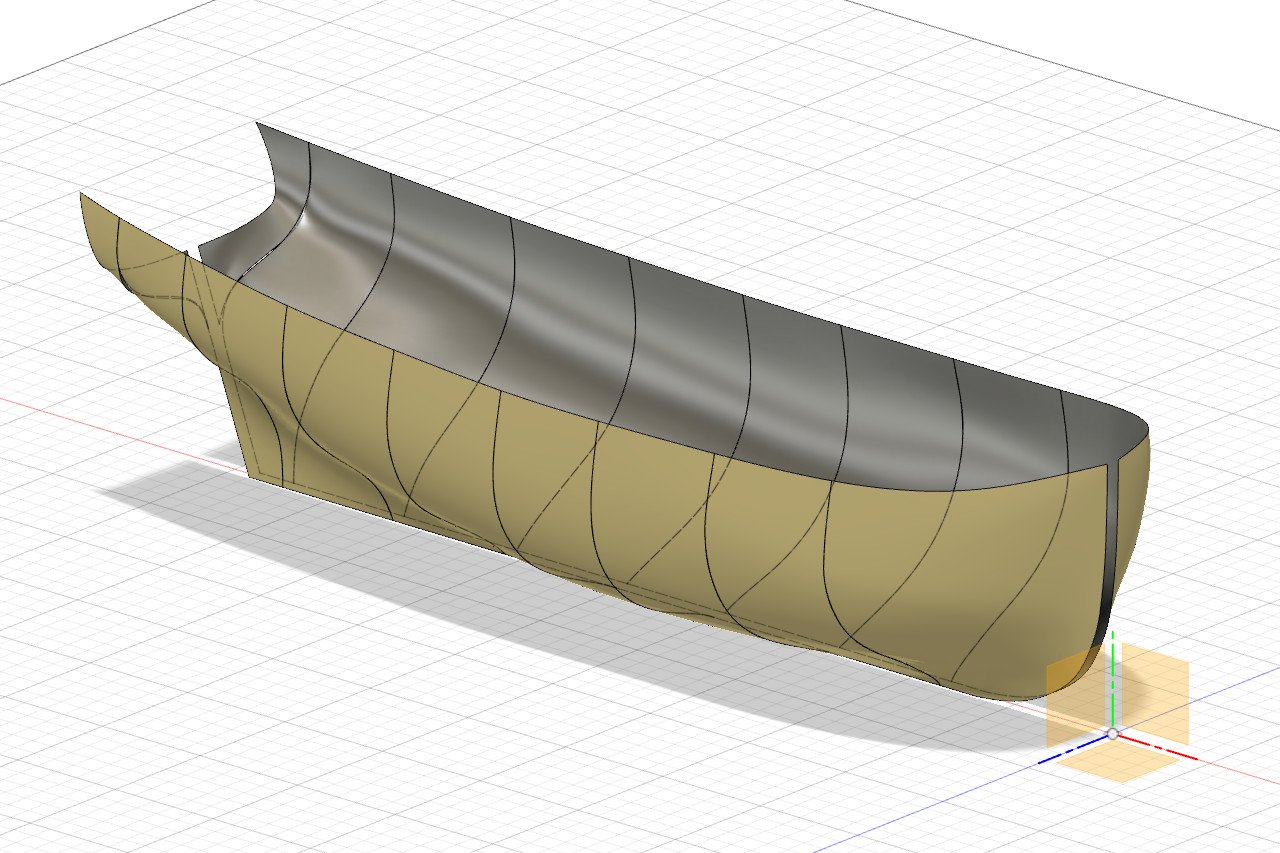
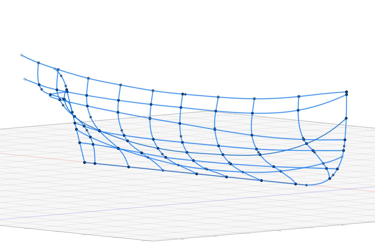
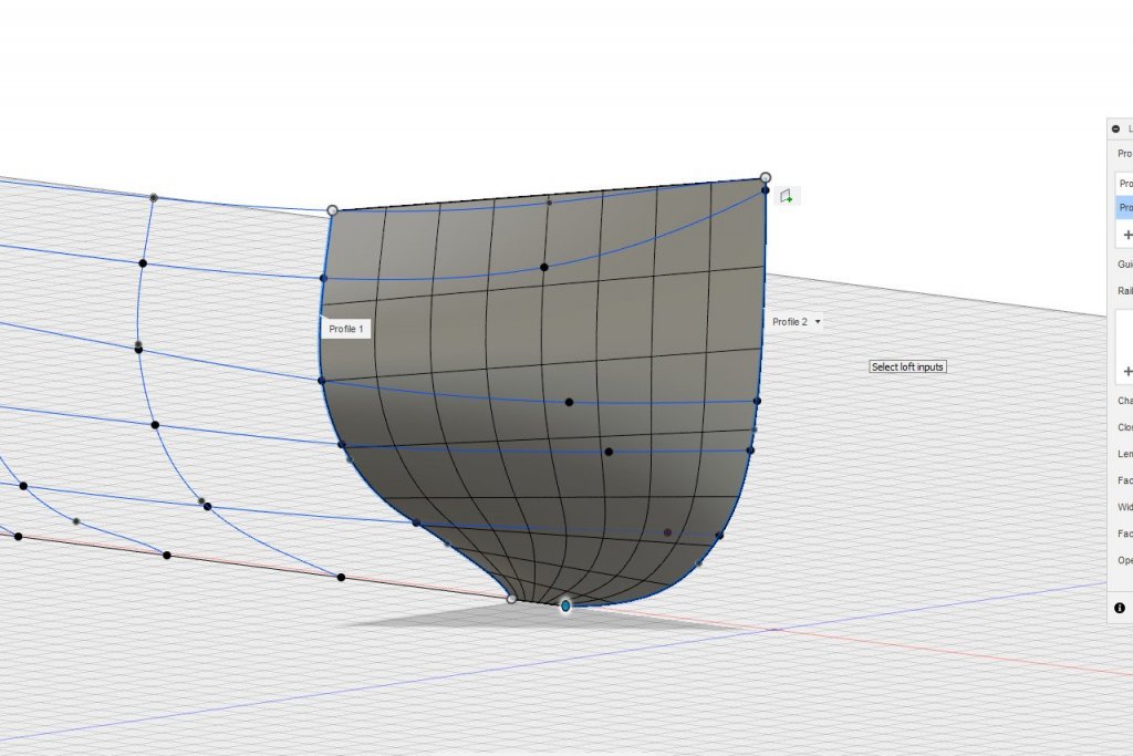
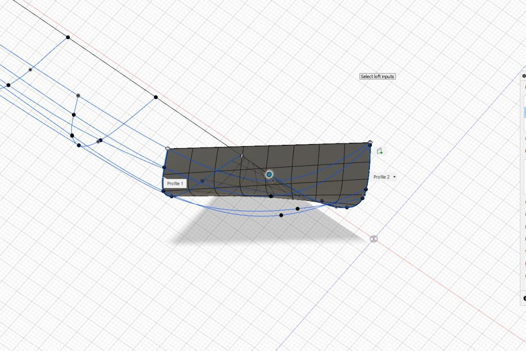
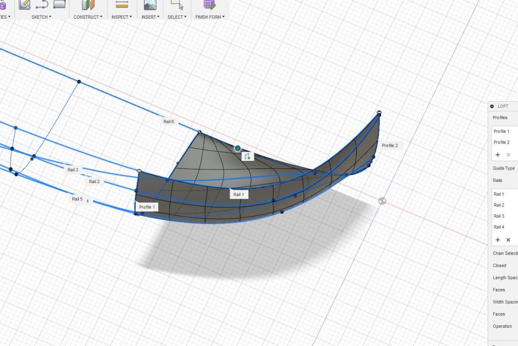
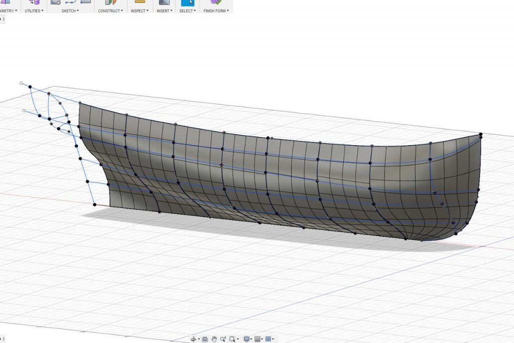
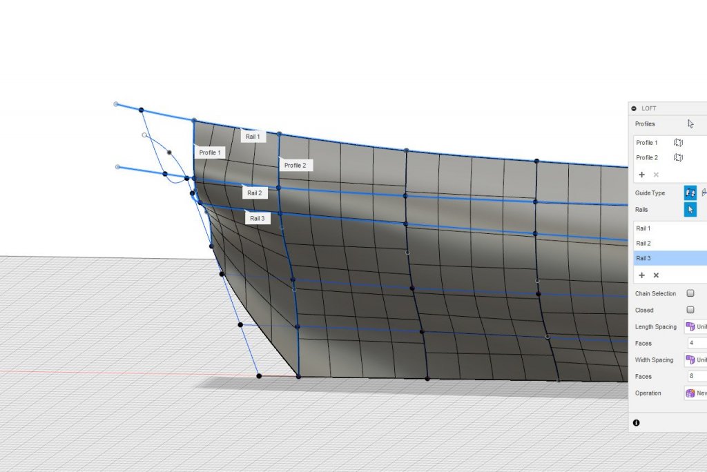
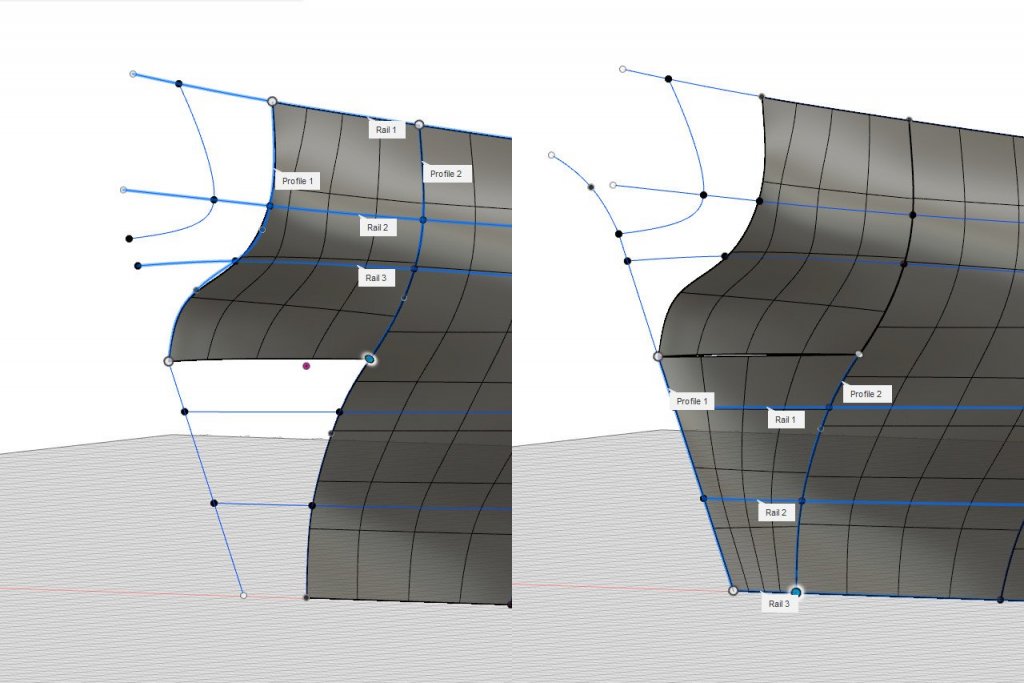
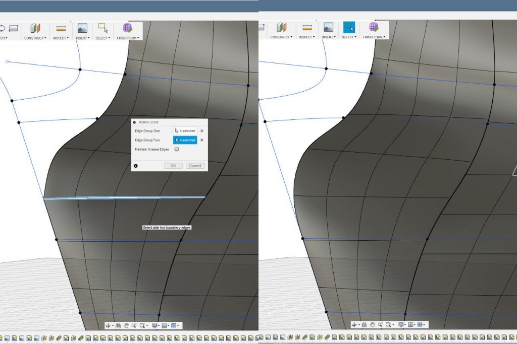
In order to establish a good ending shape for the hull, I added one more curve at the stern. This is a little guesswork since it isn't a line on the plans, but I think the shape is pretty close. Now the lofting can begin. I click on "Create Form" to enter the sculpt environment. Then Create -> Loft. When I select the start and end curves for the first loft, it looks like this. From above, it's clear that the shape isn't right when there aren't any rails. Once the rails are selected, the shape conforms to them. The surface is constructed in sections by lofting between station lines. Uh oh. The loft doesn't work back here. My solution is to loft this area in two parts. First, I break the longer station line into two parts. The top part stops at the same height as where the smaller station line ends. The remaining half of the station line matches a line along the sternpost. Then the two pieces are lofted separately. There is a little gap between the pieces. The Modify -> Merge Edge operation is used to seal the gap. I finish the lofting and create a mirror of the surface. It doesn't look too bad. The reflection in the aft area has a little wobble in it, showing the isn't quite smooth there, but I can deal with that later. It's neat, but so what? How can I use this? For my next trick, I need a volunteer (or several) from the audience to pick a number between 1 and 200.

- 222 replies
-
- 3
-
-
- sultana
- model shipways
- (and 1 more)
-
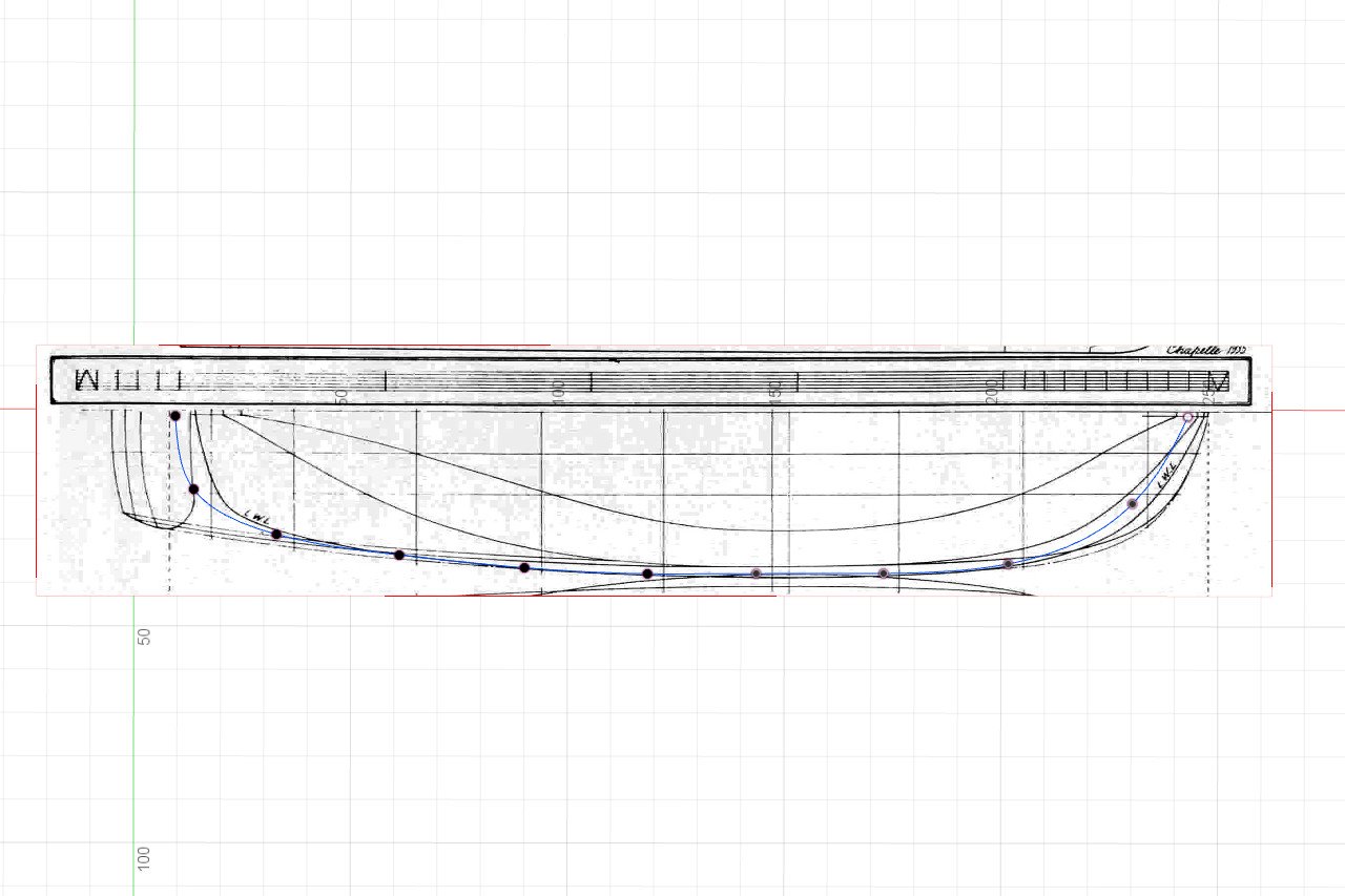
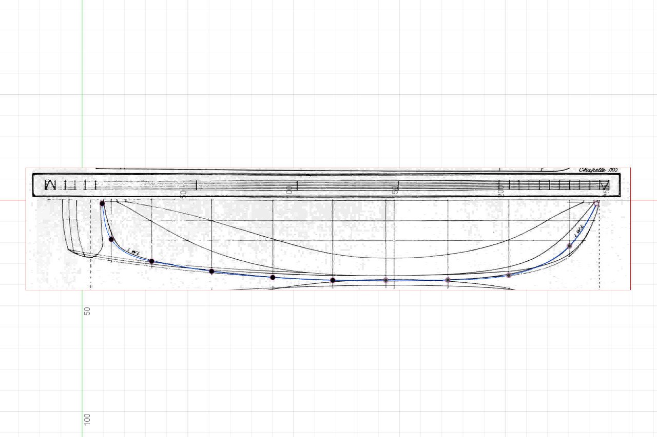
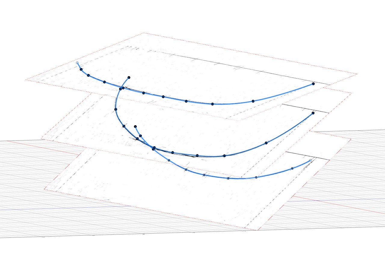
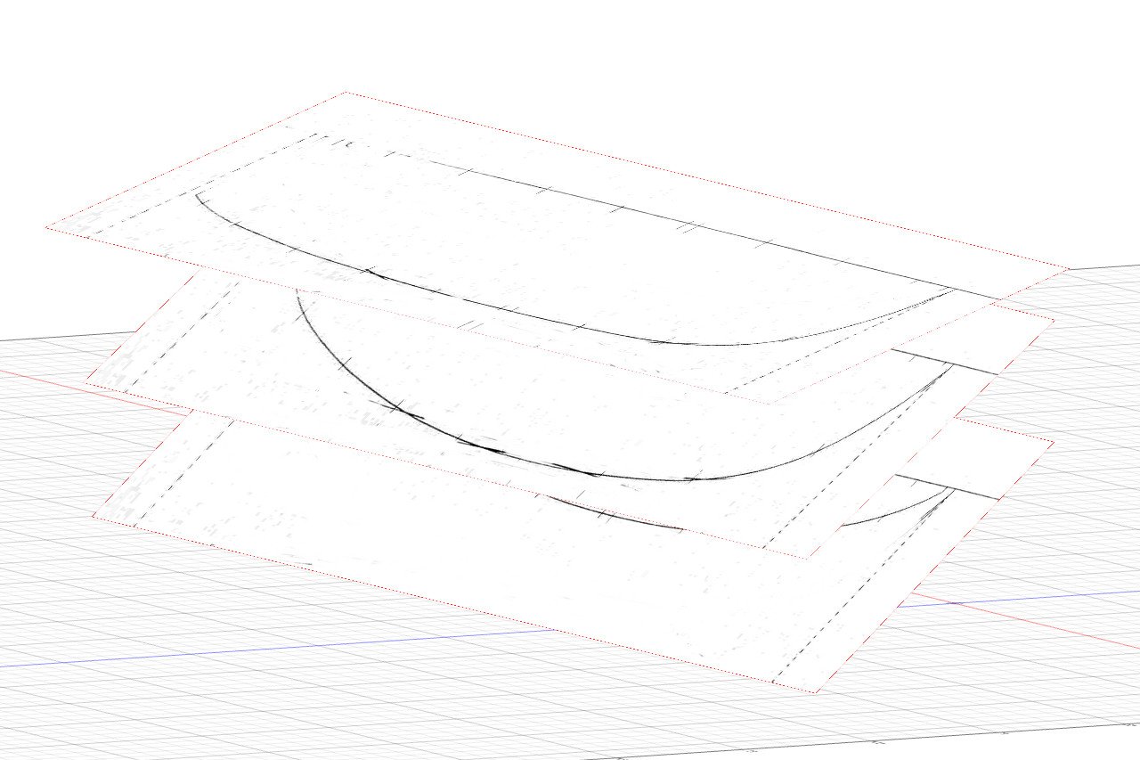
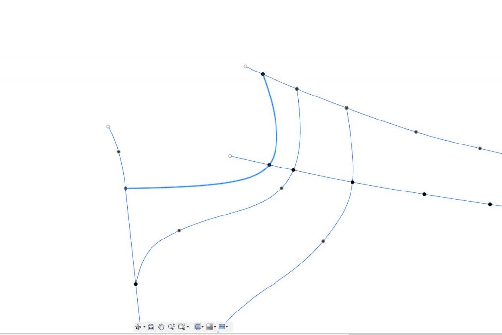
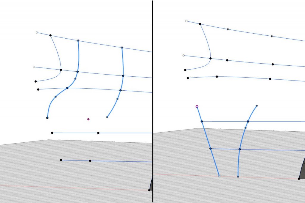
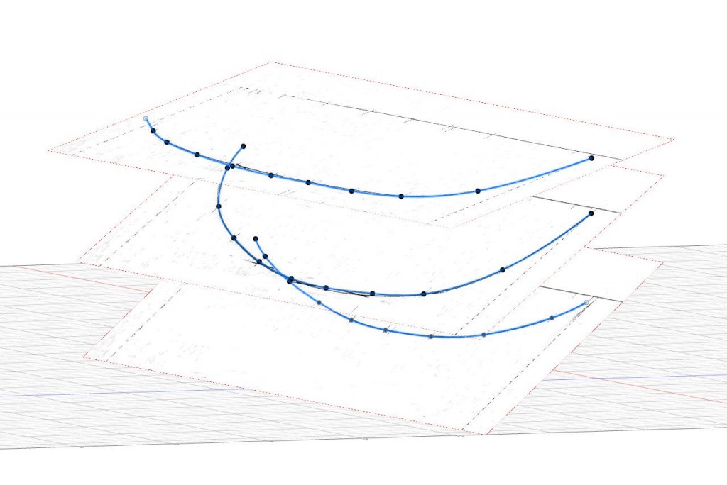
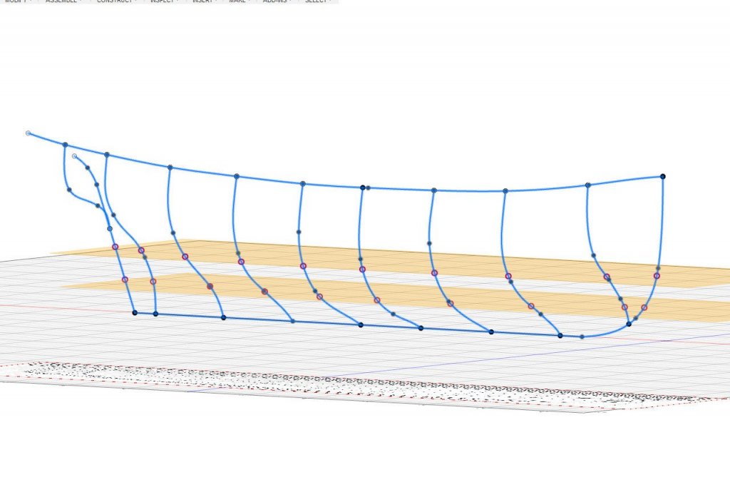
The sketching of lines continues with finding intersection points and then sketching fit point splines through those points. Here are the intersection points for the two waterlines, with the waterline planes visible. And then the splines. Drawing the lines is easy -- just a matter of connecting the dots with a little adjustment of the curves at the end. The same procedure is followed for the load waterline. But wait... The intersection points don't seem to match up to the line on the plans. Is this an error in the plans? No. This is because of how sketches work in Fusion 360. When you start a sketch, you choose the plane on which it will be drawn. Then Fusion 360 brings you to a view that is tangent to the drawing plane. Because the load waterline is tilted a little off horizontal, the view isn't directly down onto the plans. Instead, it's skewed a little, so the view doesn't match up. The load waterline drawn on the plans is a projection of the hull line down onto a horizontal surface, so to see it correctly, the view needs to be changed so that the viewport is looking directly down. See the view from directly overhead below. Those of you with sharp eyes may have noticed that aft-most portions of the load waterline curve don't quite match the line on the plans. That is an issue with the plans, as the intersection point is correct in the sheer view. I think it's close enough not to matter much. Do diagonals work like the load waterline? Are they projections down onto a horizontal surface? No, they really do get drawn directly on the tilted planes. Here are all the lines at this point. Now it's finally possible to create the hull surfaces.

- 222 replies
-
- 4
-
-
- sultana
- model shipways
- (and 1 more)
-
Thanks, Patrick. I've been closely following your Sultana build log (and the one by moreplovac too).
- 222 replies
-
- 2
-
-
- sultana
- model shipways
- (and 1 more)
-
Thanks for following along. I used Gimp to convert the plans.
- 222 replies
-
- 2
-
-
- sultana
- model shipways
- (and 1 more)
-
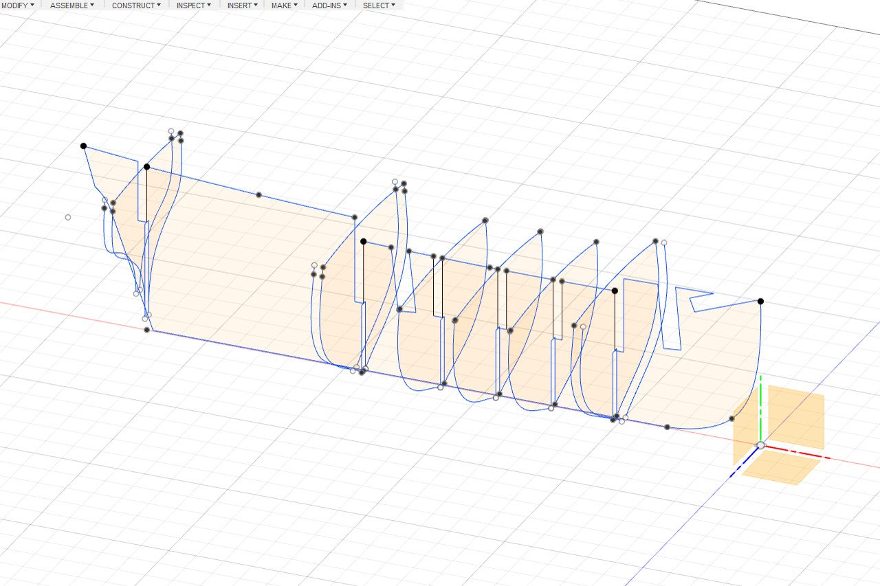
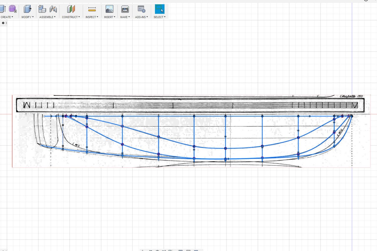
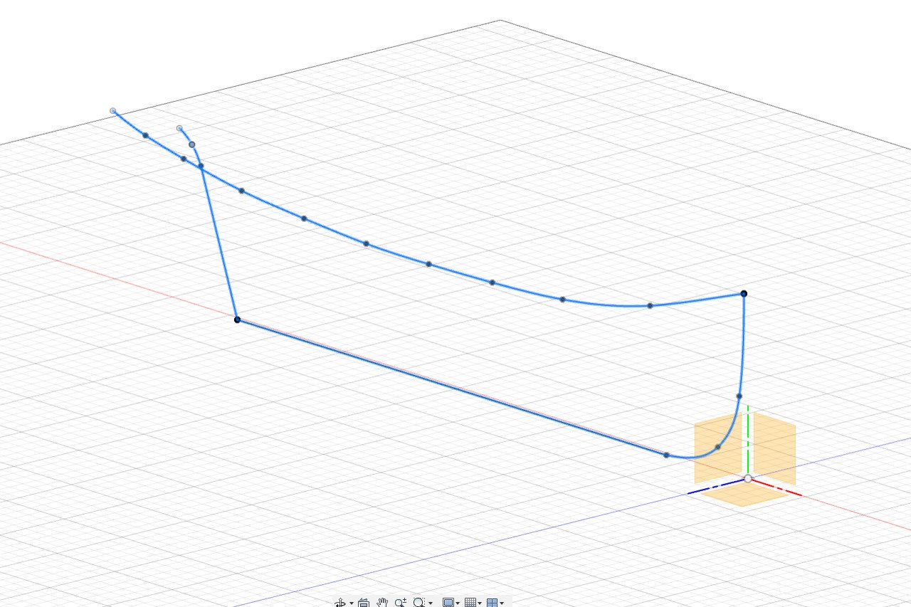
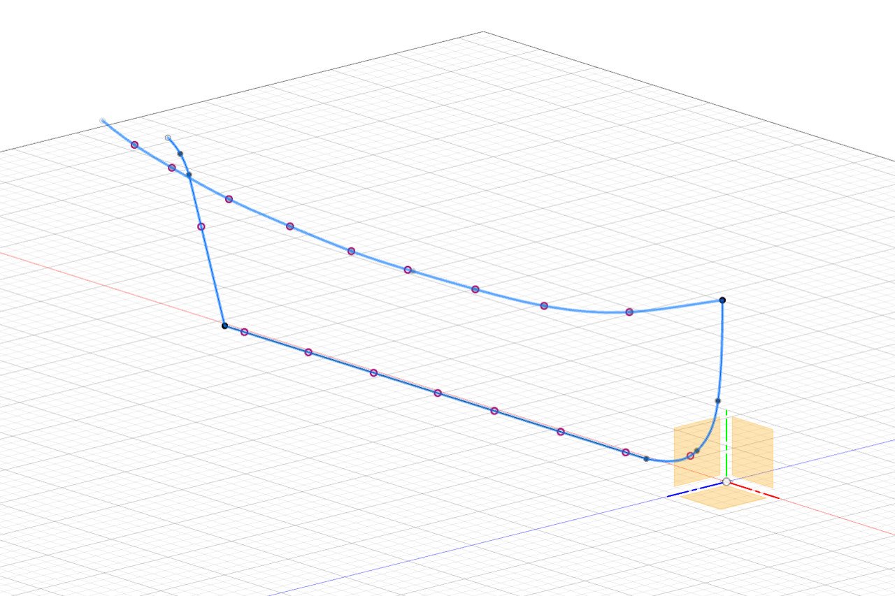
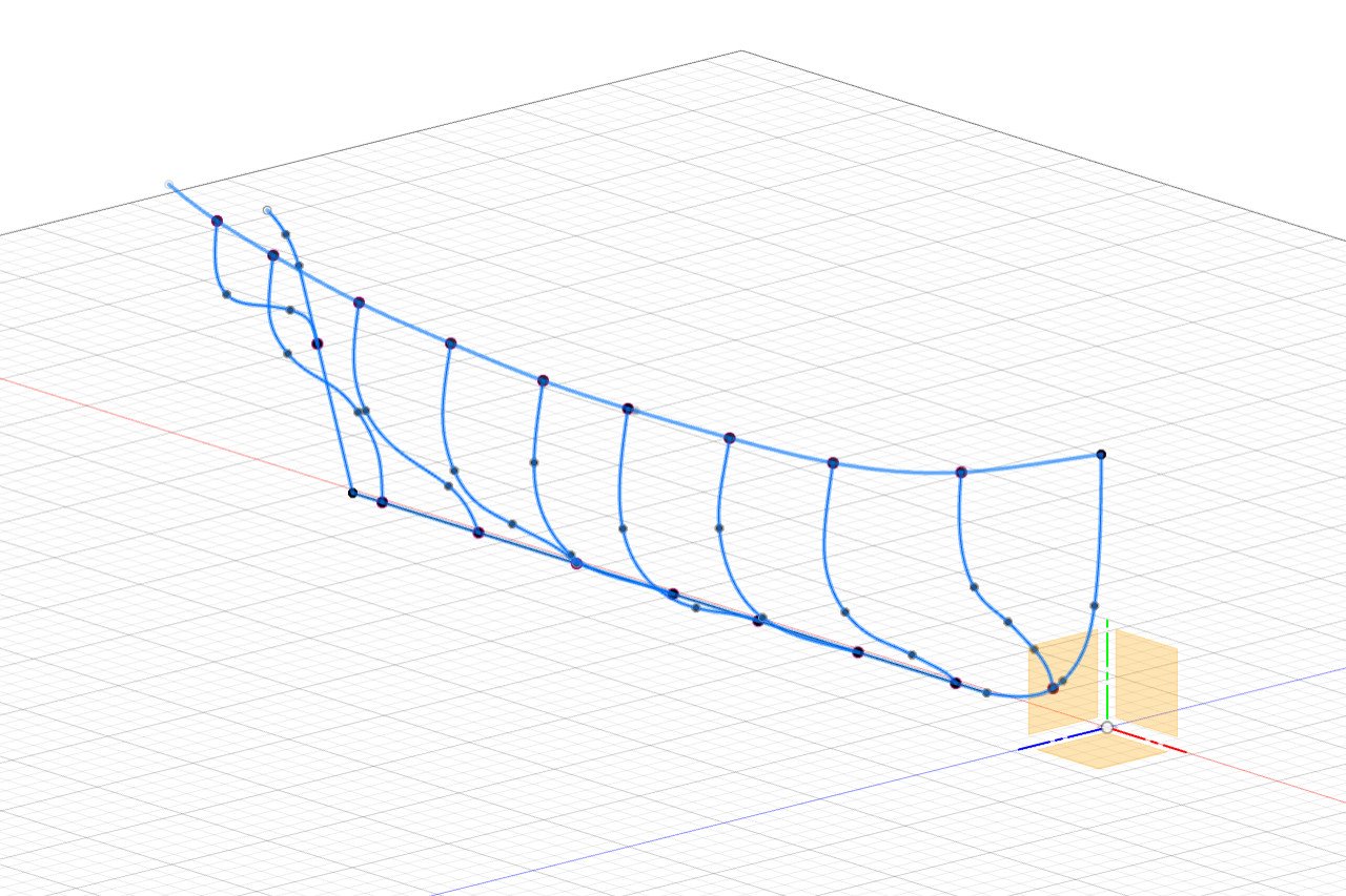
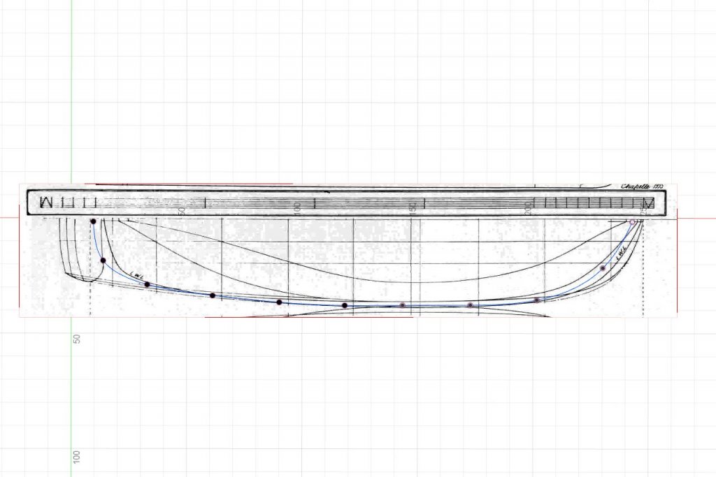
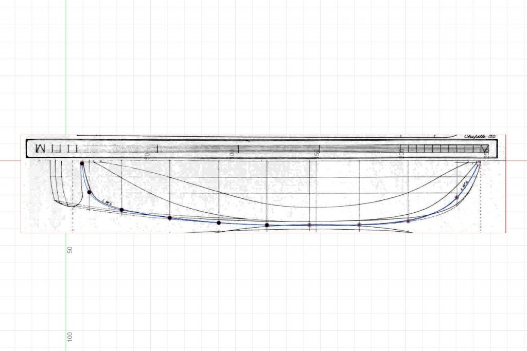
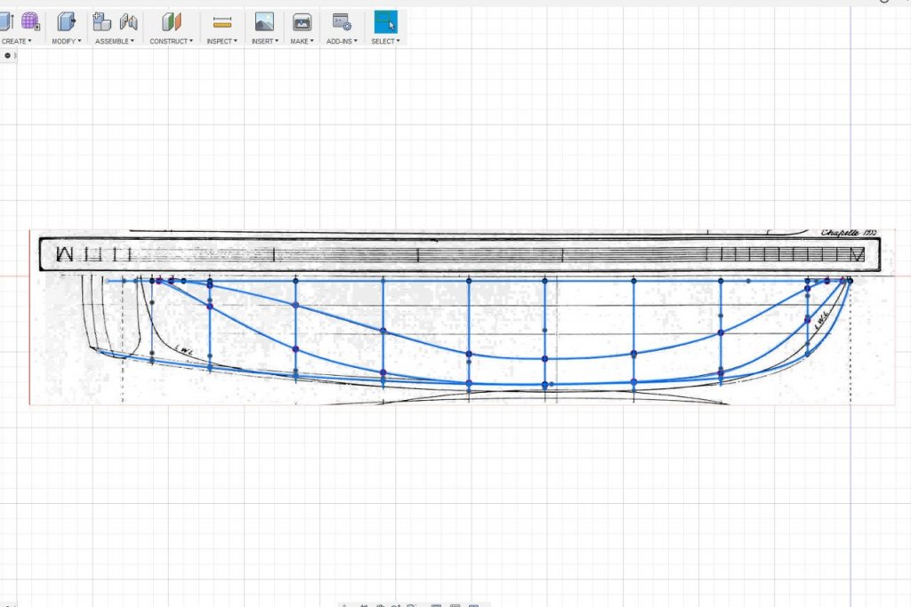
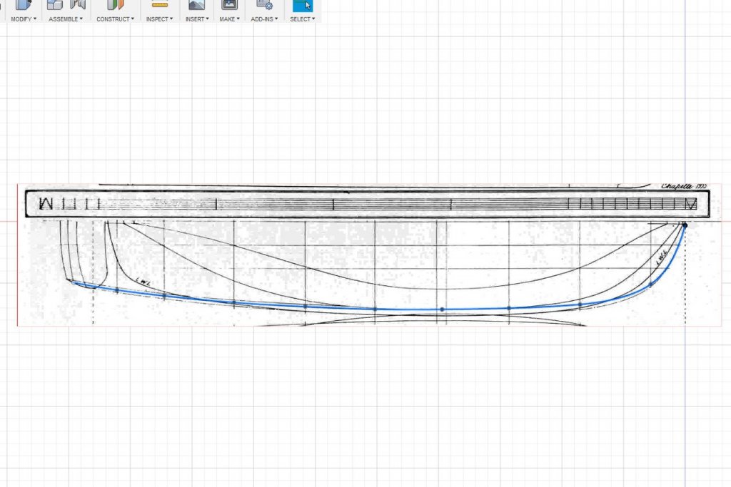
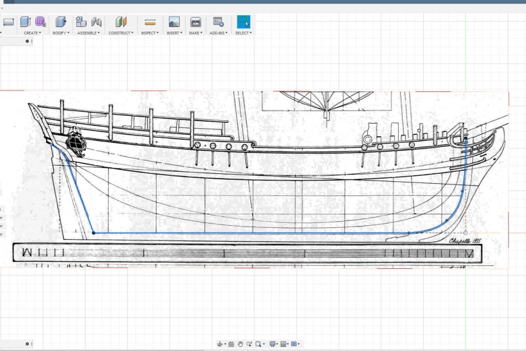
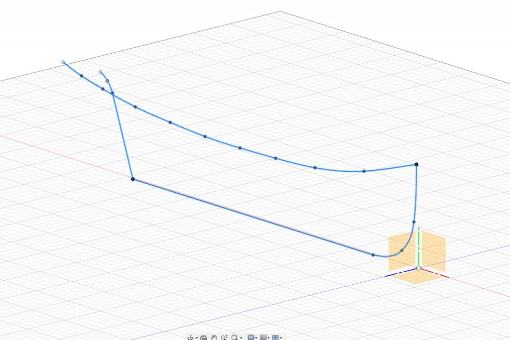
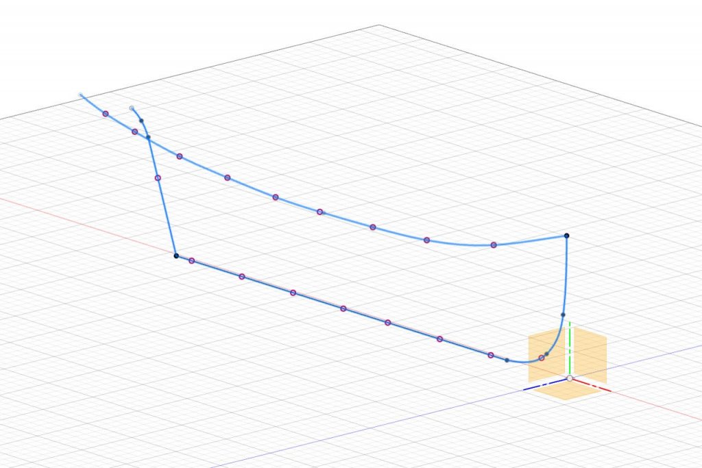
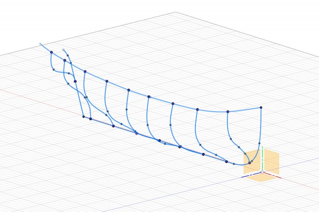
Now I'll create sketches of the various hull curves. (In the 3D/CAD forum, there is a thread where I worked through this method. You can check it out if you're interested in more details about the procedure.) For the topmost line, I will create a curve following one of the bulwark lines on the plan. To ensure correct placement, I create a construction point at the tip of the bow, which will be used as a starting point for the curve. A fit point spline is created in a horizontal plane following the curve as viewed from above. Then the points on the spline are adjusted up or down to fit the curve as viewed from the side and front. In the picture below, the curve is viewed from the front and back showing how it follows the plan. Next is a sketch for the rabbet line. It is composed of several lines and curves. The sketch is drawn in the false keel thickness offset plane. The same starting point at the bow is used to start the bow curve, meaning that the bulwarks curve and bow curve intersect at that point. Here are the two sketches so far. Now I select the construction plane for station 1, then go to Sketch -> Project/Include -> Intersect and click on the existing lines to find the points where they intersect with the plane. This is repeated for each station plane. The intersection points are displayed as purple circles. Using the intersection points as start and end points, a fit point spline is sketched for each station following the curves on the body plan. Why all the intersection points? Later on, I'll be using the loft and rails feature in the Fusion 360 sculpt environment. Loft creates a surface between two or more curves (profiles). Rails can be used to adjust the flow of the loft. However, all rails used in a loft must intersect all profiles. To make sure all the curves intersect as needed, I find the intersection points first, and draw fit point splines using those intersection points. Next time, sketching continues.
- 222 replies
-
- 6
-
-
- sultana
- model shipways
- (and 1 more)
-
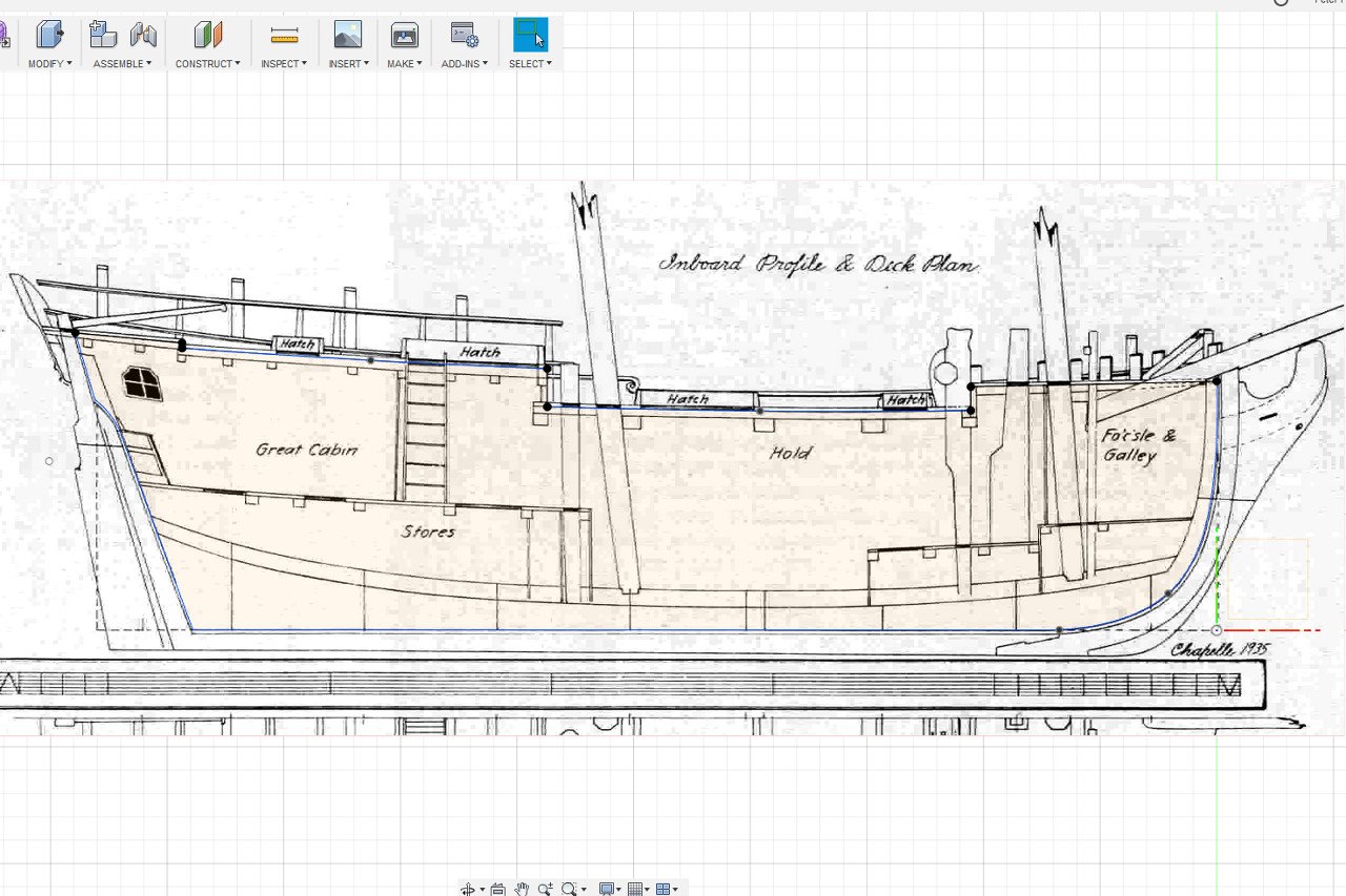
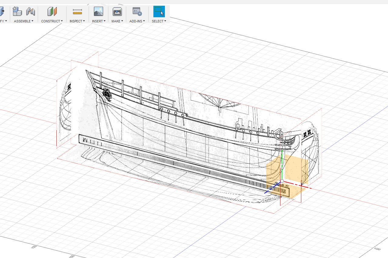
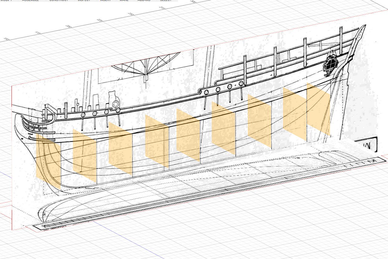
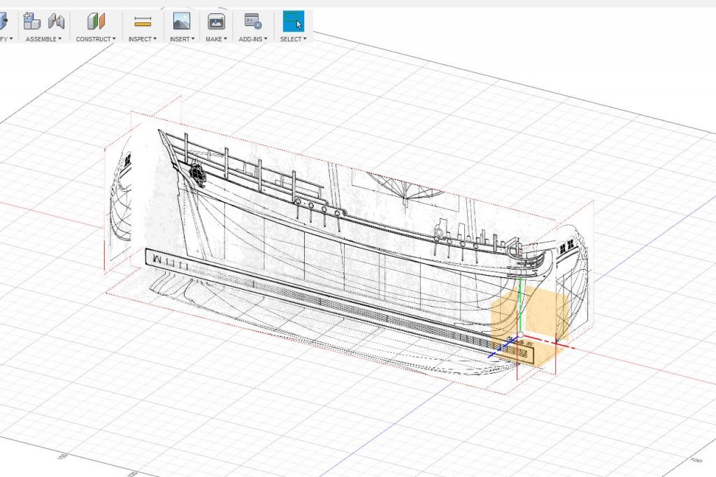
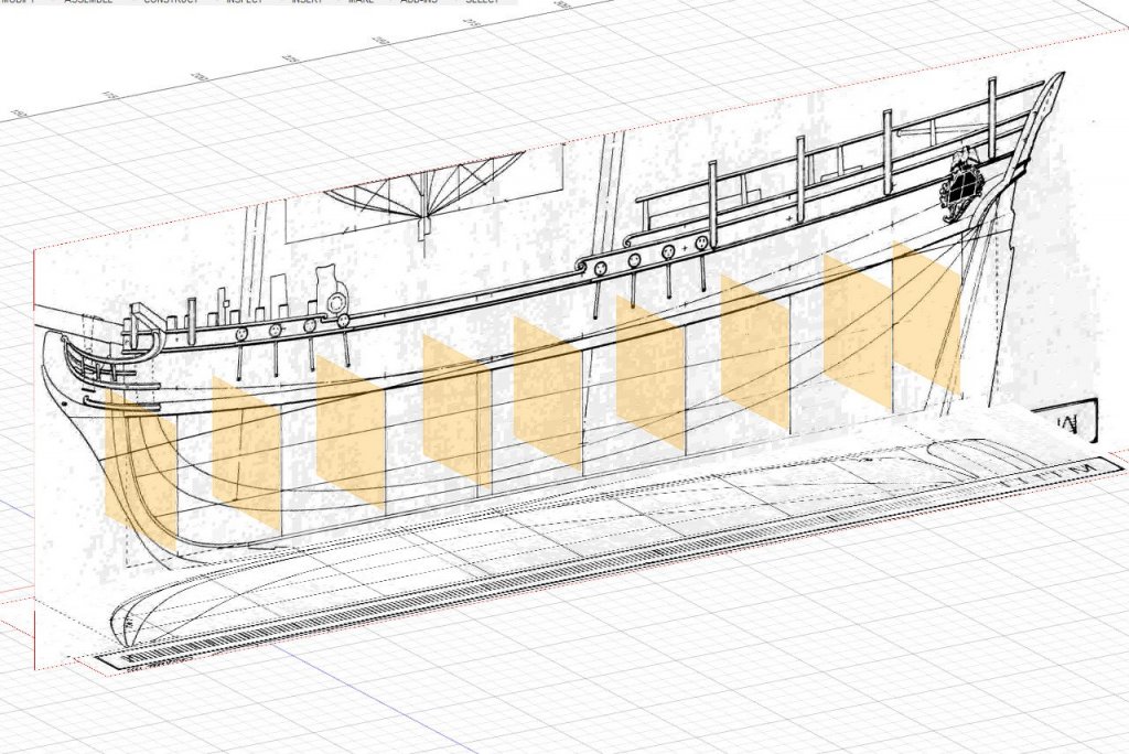
Step one is to bring the plans into Fusion 360 as canvas objects. The plans are checked to make sure that all lines are perfectly horizontal / vertical, and that lines in one view match up to the corresponding lines in a different view. The images have been scaled in the 3D environment to match the scale of the model (1:64 or 1 foot = 3/16"). The 3D origin is at the intersection of the baseline, the centerline, and the forward perpendicular. A number of construction planes are defined. Here are the station planes. And the two water lines plus the load water line. Planes for the three diagonals are also defined. And canvas objects for the diagonals are added to the environment. A final, and very important, construction plane is one which defines the thickness of the false keel. I plan to use 1/8" thick wood for the false keel and bulkheads. Converting to metric, that's 3.2mm. But because I am only building a half hull now, which will be mirrored later, I will set the false keel offset plane to be 1.6mm from the centerline. With the reference images imported and the construction planes defined, the environment is ready for the hull modeling to start.

- 222 replies
-
- 6
-
-
- sultana
- model shipways
- (and 1 more)
-
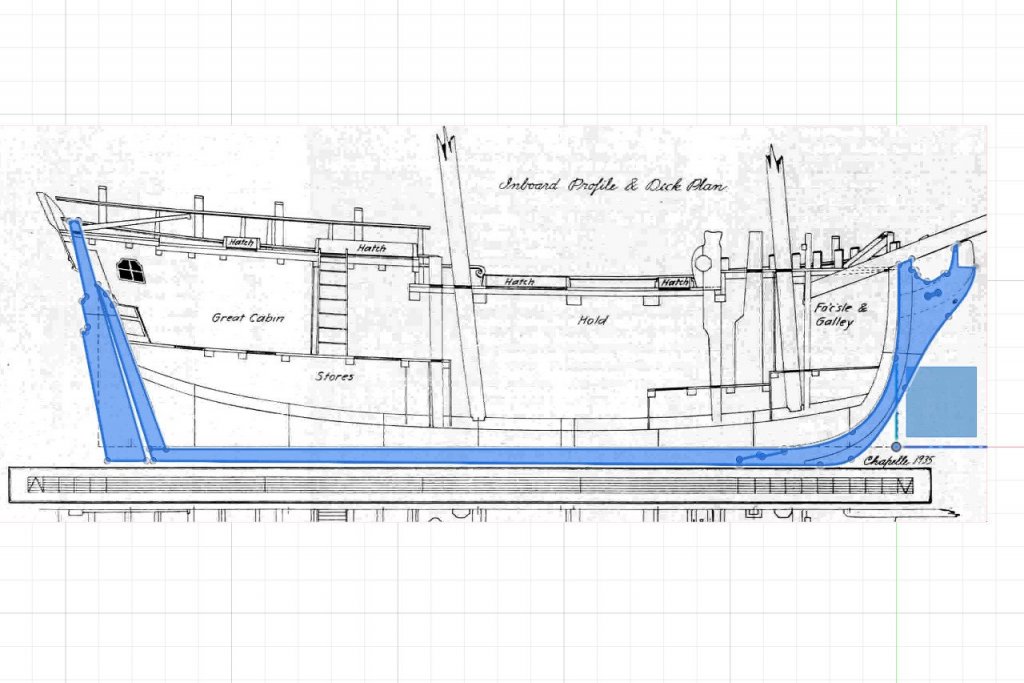
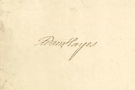
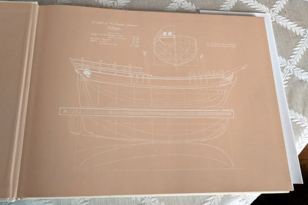
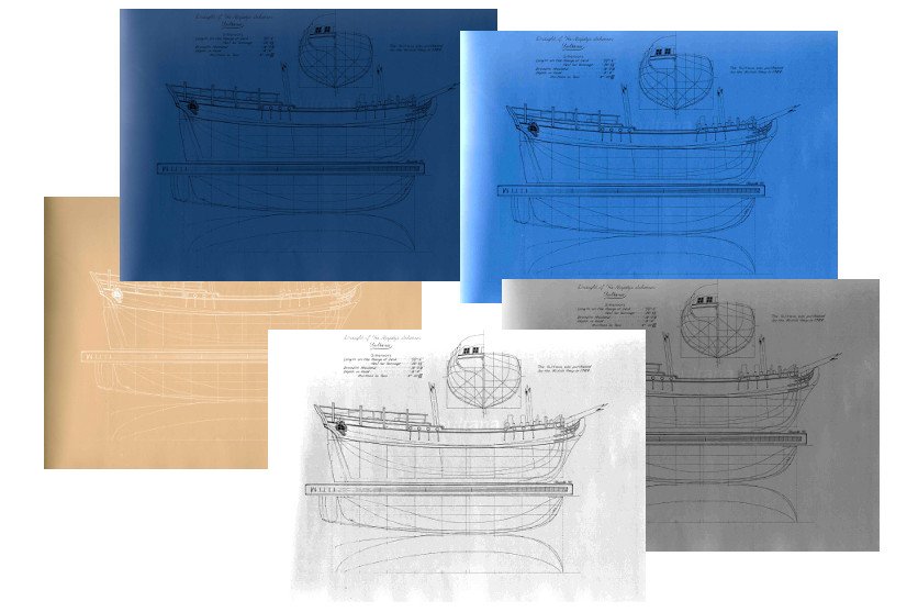
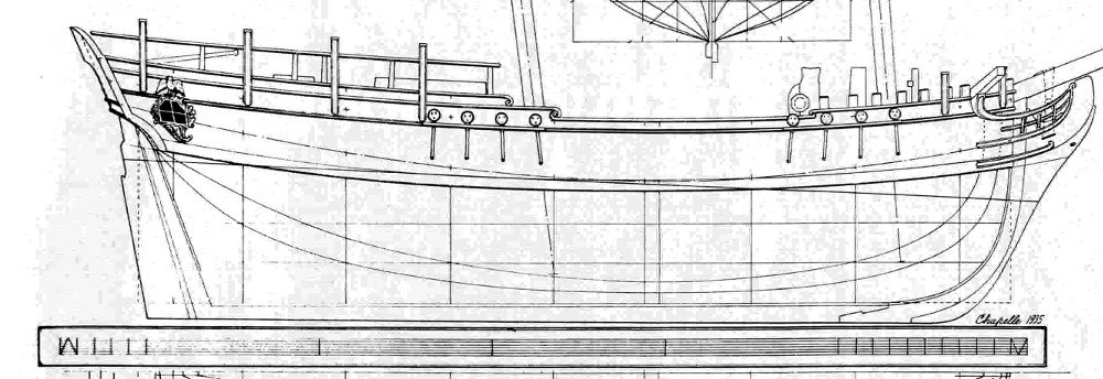
My plan, which I hope is not too ambitious, is to make a plank on bulkhead hull. I have access to a local makerspace with a laser cutter, so I intend to laser cut the pieces. I'd like to develop a workflow of going from plans to parts that I can apply to future projects. Let's look at the plans of the Sultana. Follow this link to see the original plans on the National Maritime Museum website. I suspect most visitors to MSW are familiar with the circumstances of the Royal Navy acquiring and recording the lines of the Sultana. Who exactly did the work of recording the plans, at Mr Randall's dock in 1768? Was it this guy whose name is in the corner? Adam Hayes? You probably know how the plans were cleaned up and recorded by Howard Chapelle in 1935. The Chapelle plans are reproduced on the end papers of the Schooner Sultana book. In white on orange... Thanks guys. Scan, invert colors, levels, convert to grayscale, more levels, crop into separate files. That's better. What stands out about the plans is how few station lines there are. Just nine. Was Mr. Hayes in a rush to meet his mates at the pub that day? Often, the plans of a larger ship will have 20 or more stations, and a modeler can just choose all or some, make bulkheads directly from those lines, and be done with it. But nine isn't enough. Based on my one and only plank on bulkhead experience, I want more bulkheads. I want lots of bulkheads. It's time to find my bulkhead lines. It's time to go to the drawing board start up the CAD software.
- 222 replies
-
- 5
-
-
- sultana
- model shipways
- (and 1 more)
-
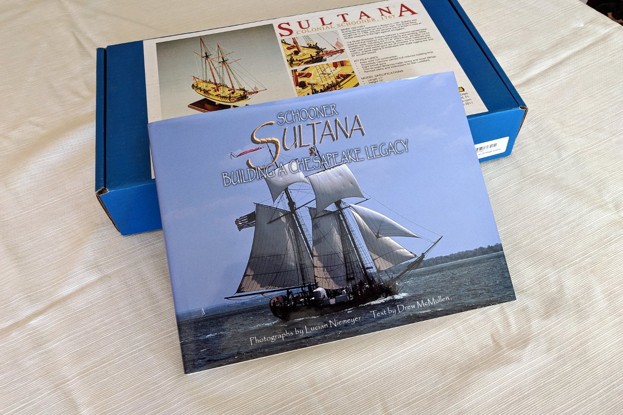
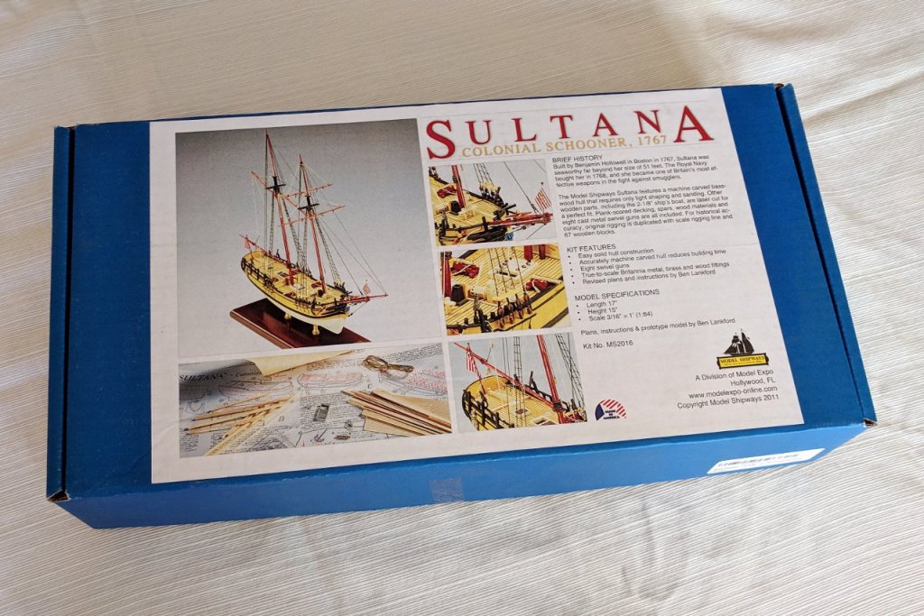
Welcome to my Sultana build log. I plan for my Sultana to deviate from the kit in two significant ways. First, I will be modeling the 2001 Sultana replica, rather than the 1767 original. In addition to pictures taken by myself and others, I'll be using the book Schooner Sultana: Building a Chesapeake Legacy by Drew McMullen with photos by Lucian Niemeyer. The book covers the construction of the 2001 ship with lots of descriptions and photographs. Best of all, there is an appendix with measurements of many of the main components. The second significant deviation is this.

- 222 replies
-
- 5
-
-
- sultana
- model shipways
- (and 1 more)
-
Thanks for sharing, Jim. It's good to see someone else doing similar work. I haven't gotten familiar enough with the T-Spline editing tools, but it looks like it's worth the effort.