SardonicMeow
-
Posts
333 -
Joined
-
Last visited
Content Type
Profiles
Forums
Gallery
Events
Everything posted by SardonicMeow
-
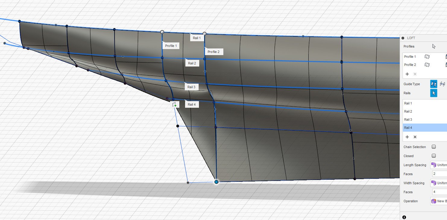
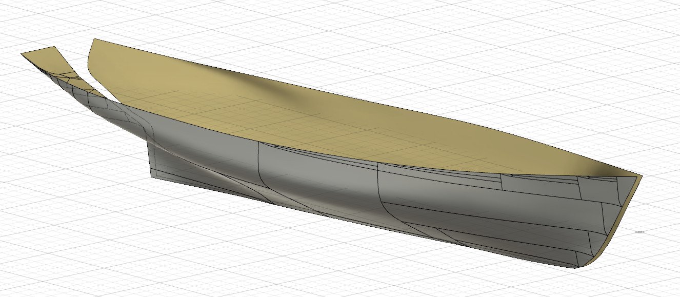
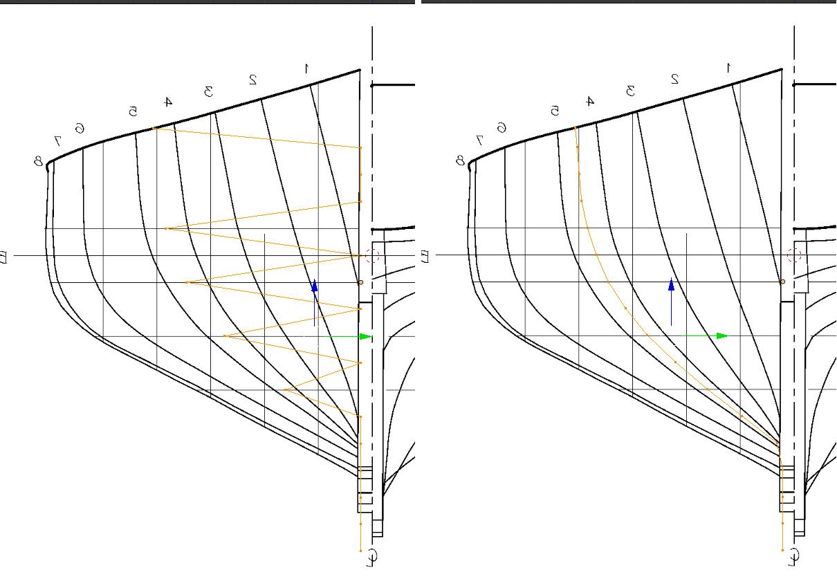
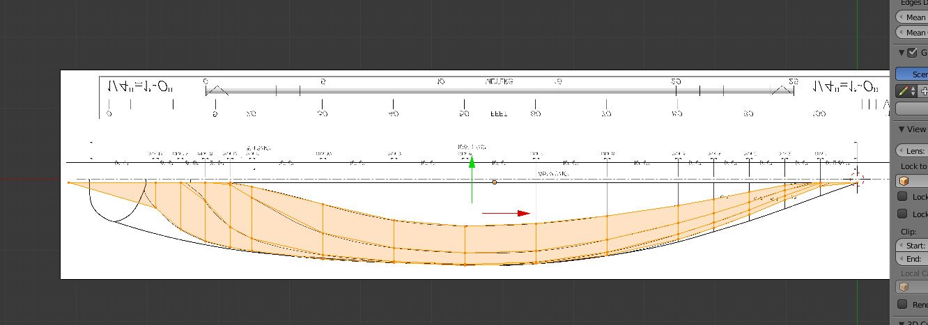
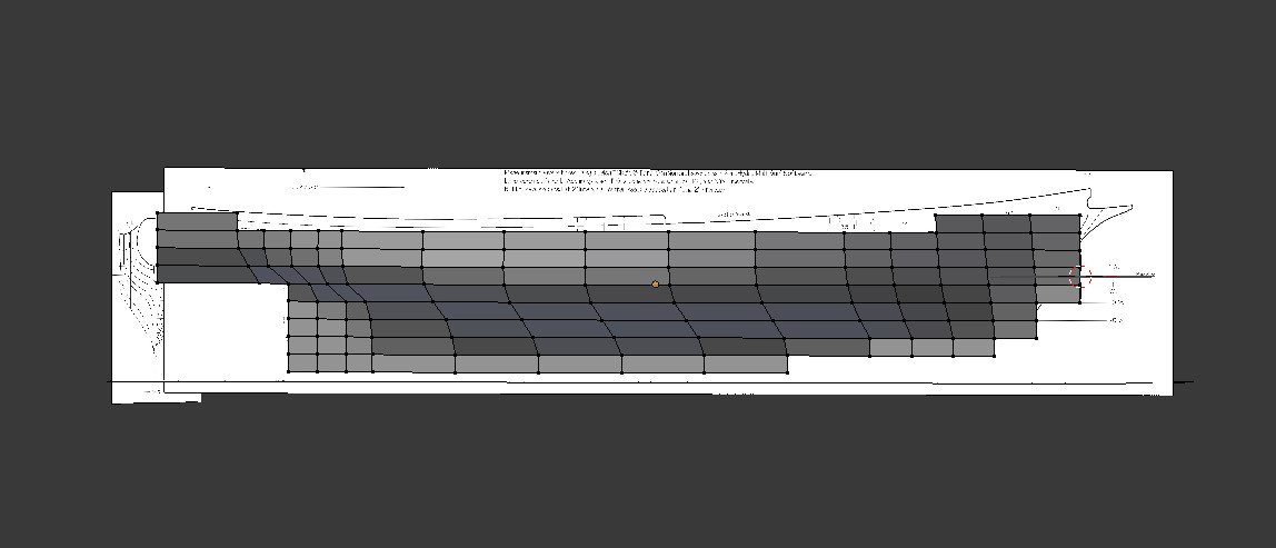
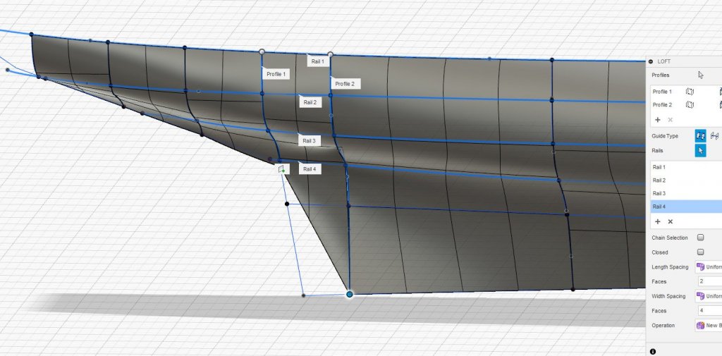
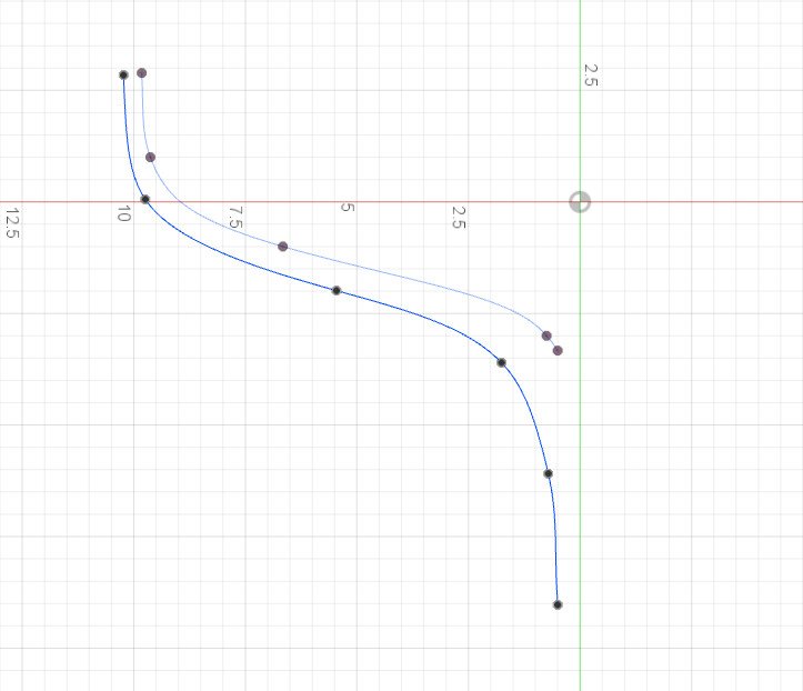
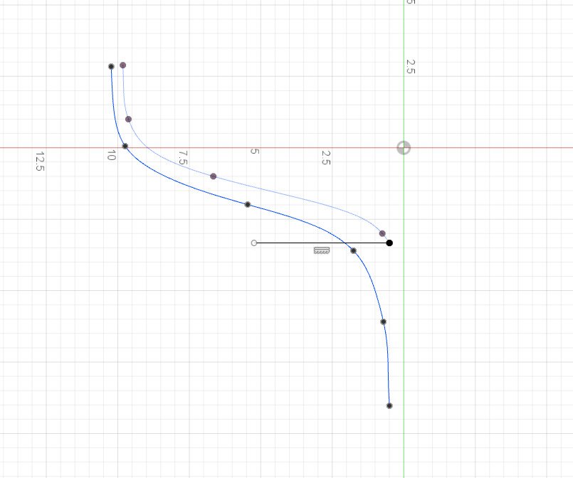
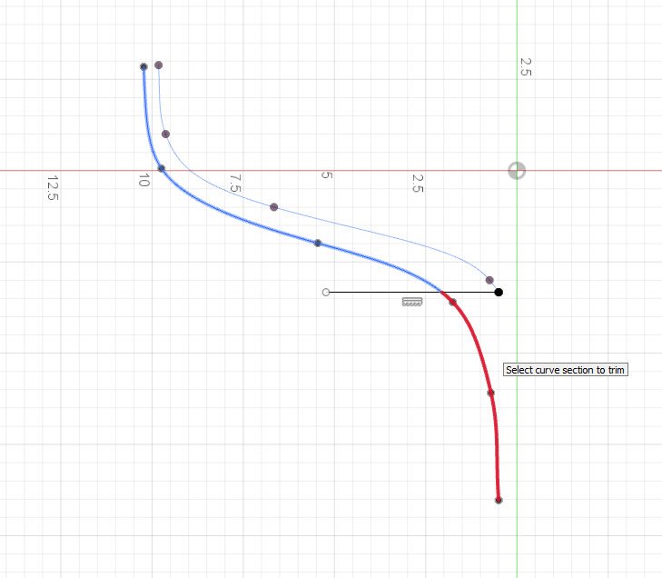
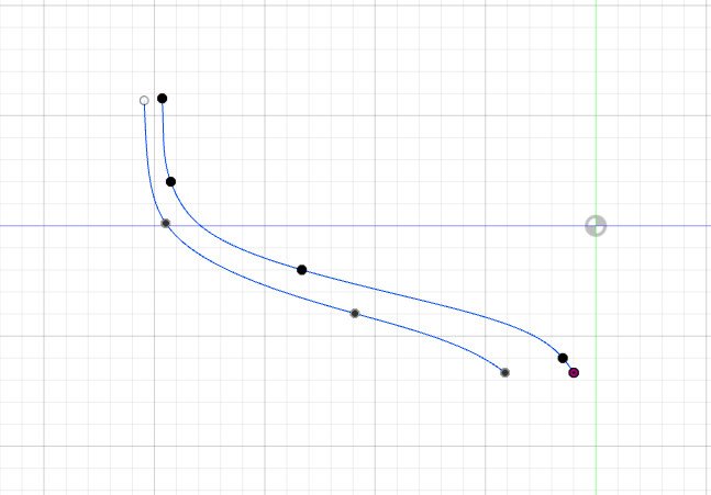
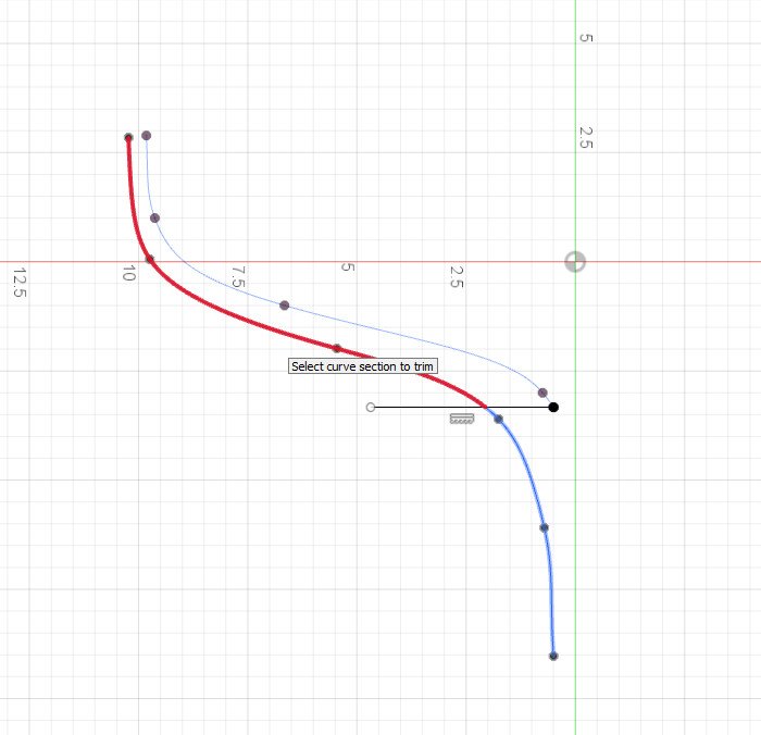
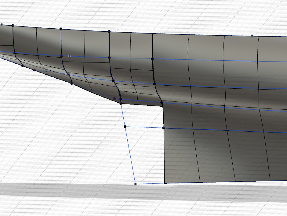
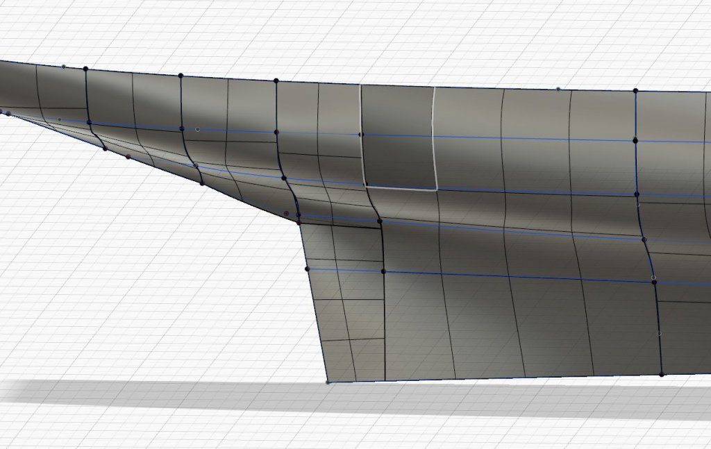
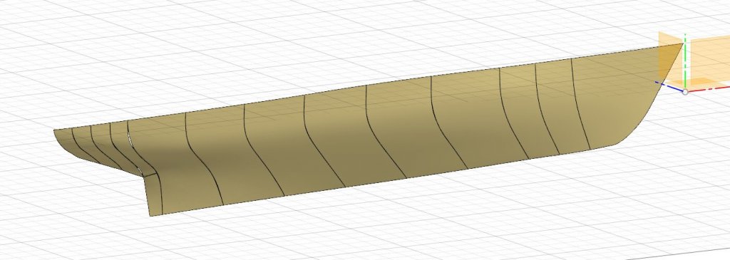
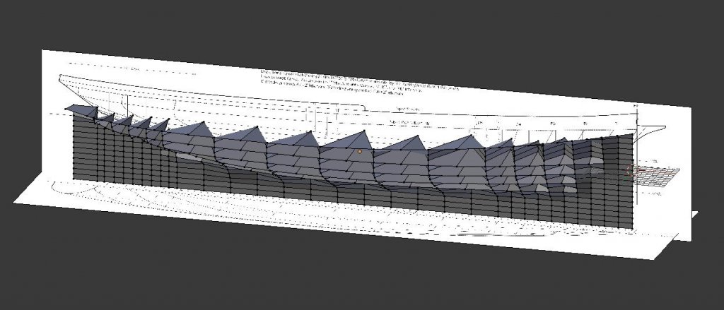
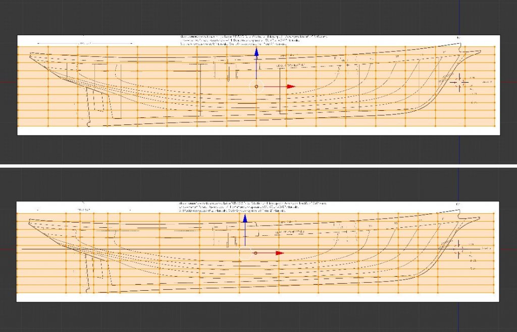
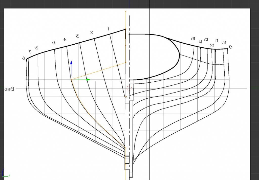
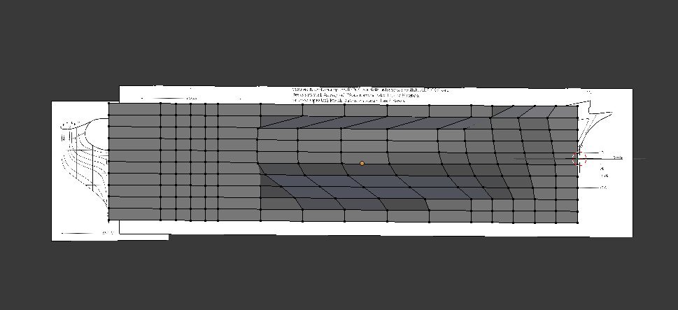
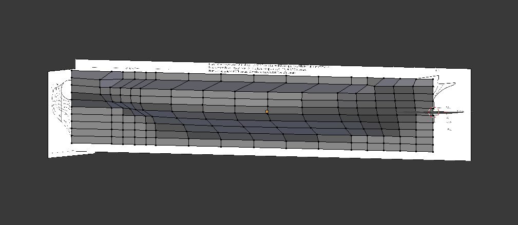
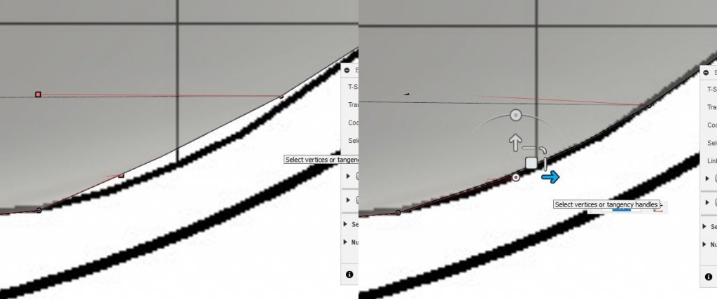
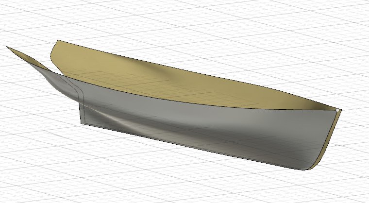
 I have been thinking about how the hull could be lofted in pieces rather than all at once. Each section between stations would be lofted, using whatever rails are common to the two. In the end, there would be an option to combine the pieces together. Here are the first several sections. And so on down the line. You'll notice that I skipped one section, because it's problematic. What to do here? If I loft between the two stations, the back end of the keel isn't covered. I realized I need to break this into two parts. One loft at the top from the smaller station (#12) to the upper part of the larger station (#11). Then a separate loft from the back end of the keel to the bottom part of station 11. To do this, I needed to break the larger station into two parts, while also retaining an intact copy for lofts forward. First, I highlighted the curve of station 11 and hit Control-C. Then I started a new sketch in the same plane and hit Control-V to paste. That was repeated to get three copies of the station line. The original will remain untouched. Copy 1 will be cut leaving only the upper part and copy 2 will be cut at the same spot, leaving only the lower part. Let's work on copy 1 (upper) first. I edit the sketch, and keep station 12 visible. Next I sketch a line from the bottom point of station 12 running horizontally to cross over the curve of station 11. Now I go to Sketch -> Trim. When I hover over the bottom portion of the curve below the line, it's highlighted in red. I click to remove the red portion of the curve. Here is the final result. Working on the second copy, the same procedure is repeated, but the top portion of the curve is trimmed. Only the blue portion remains. Now I can complete the lofting. First, I loft from station 12 to the copy of station 11 containing the top of the curve. And then the bottom part is lofted from the back end of the keel / sternpost line to the bottom of the station 11 curve. The final result is a set of surfaces that is an improvement over my earlier attempts at sculpting the hull as a single surface. You will notice there are some thin gaps between the surfaces in the aft area of the hull. I think if I loft using a larger number of faces, the surfaces will fit better to the curves and reduce those gaps. I did try using the edge merge tool in the Sculpt environment, but I ended up with distortions in the smoothness of the surface at the merge areas. It's not as good as the results I got from importing a mesh built in Blender (see my Blender thread for details) but it's the best result so far.
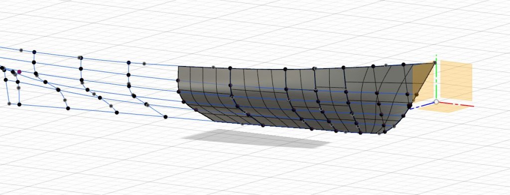

-
Hull modeling with Blender
SardonicMeow replied to SardonicMeow's topic in CAD and 3D Modelling/Drafting Plans with Software
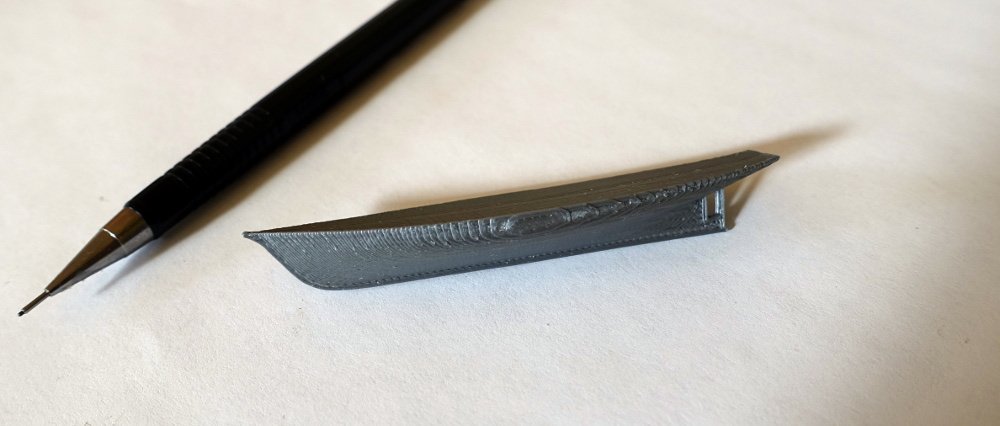
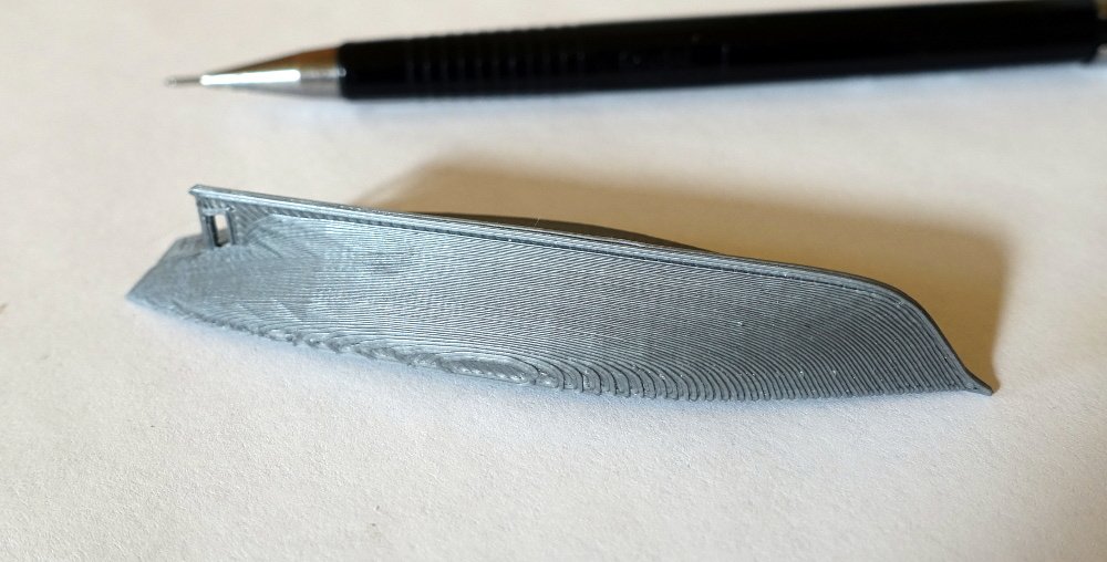
Two weekends ago I assembled a 3D printer kit. I added a keel to the Ernestina in Blender, then 3D printed the model. I probably should have added the bulkheads to make it look a bit better.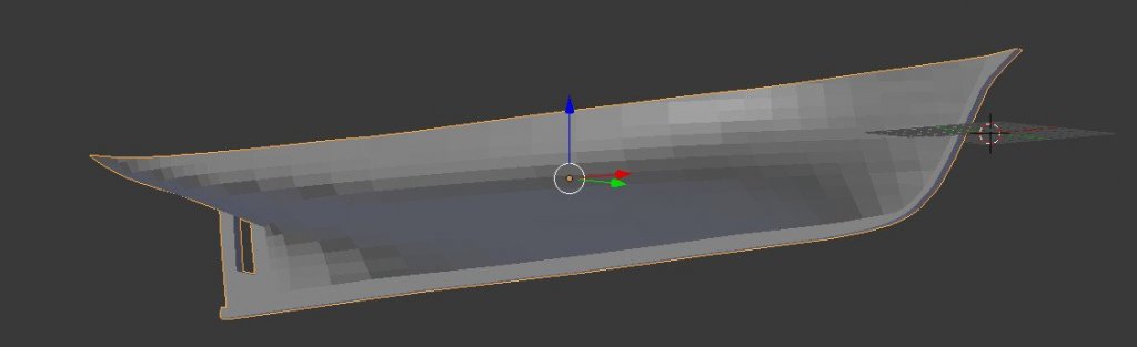
-
Hull modeling with Blender
SardonicMeow replied to SardonicMeow's topic in CAD and 3D Modelling/Drafting Plans with Software
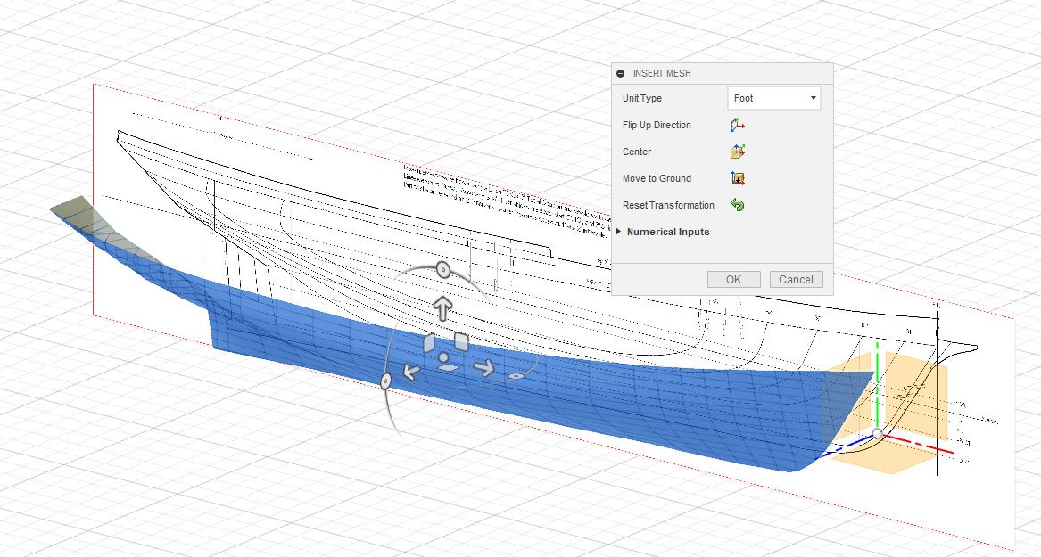
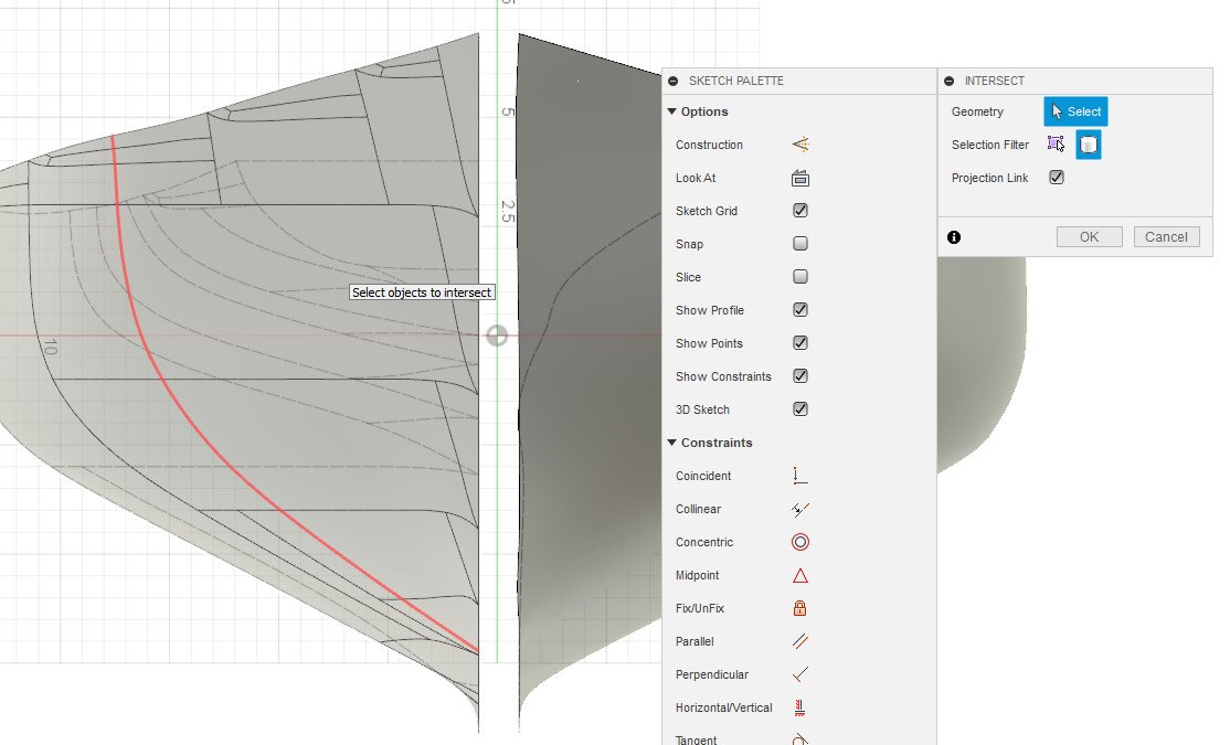
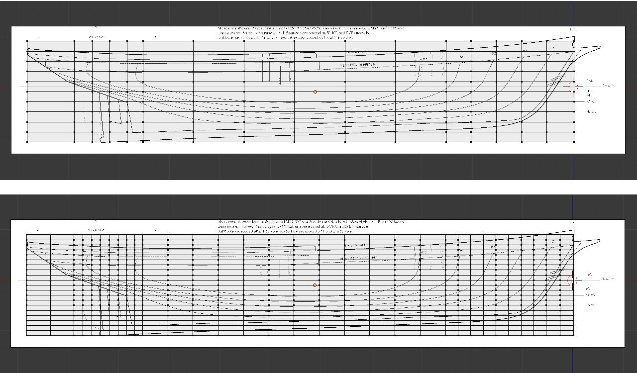
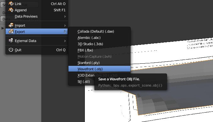
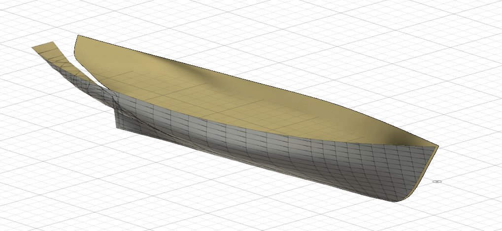
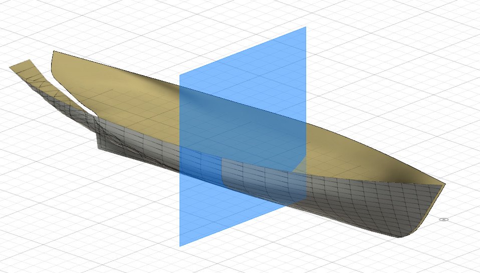
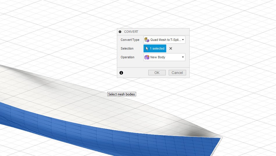
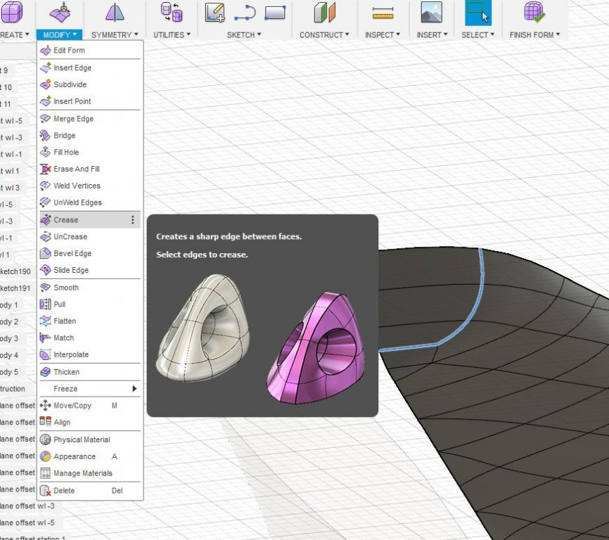
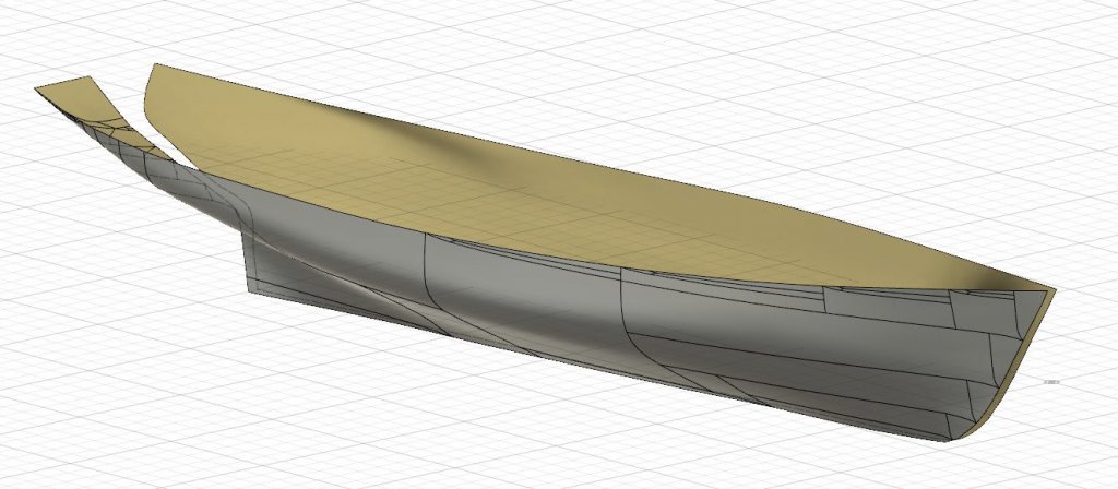
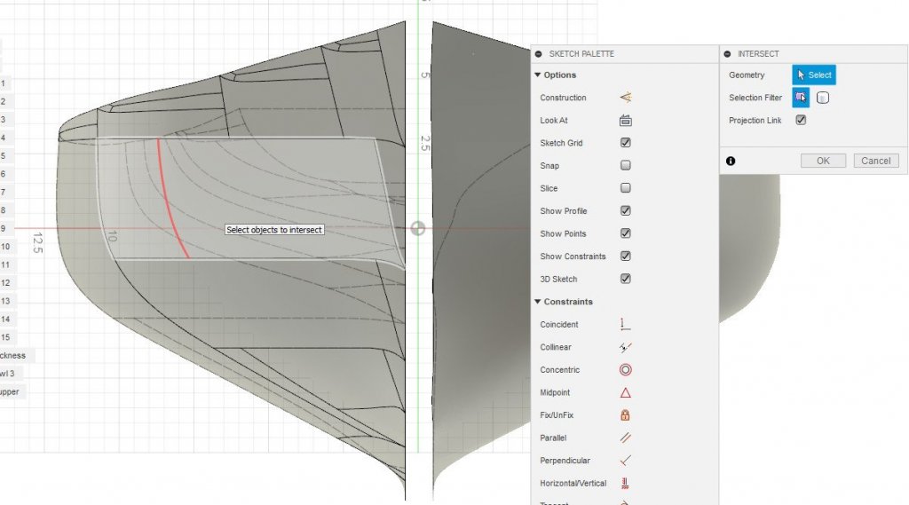
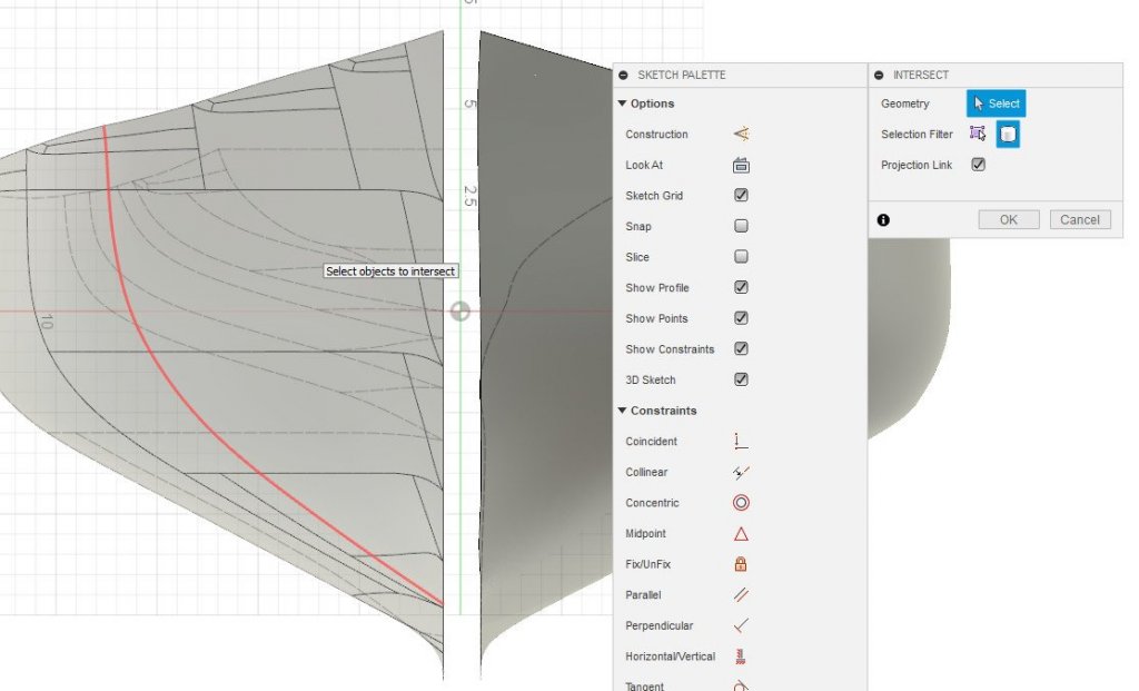
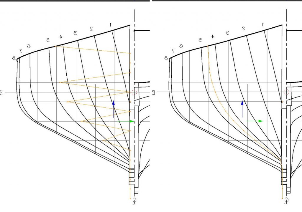
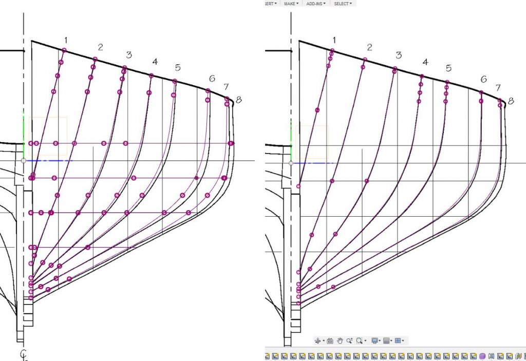
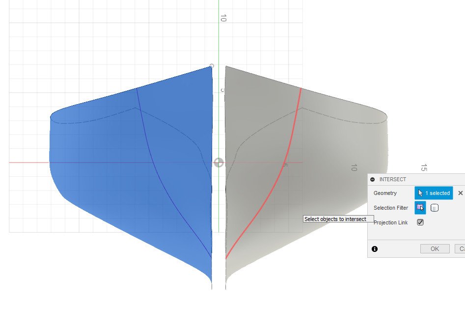
As I mentioned in my Fusion 360 thread, my goal in all of this is to create a 3D surface that can be sliced at arbitrary locations to generate intersection curves, then use those curves for a plank-on-bulkhead model. While Blender has some intersection tools, I found the ones in Fusion 360 to be much easier to use. Then the question is: how to bring the mesh from Blender into Fusion 360? The first step is to export the mesh. In Blender, go to File -> Export. There are several file formats available, but the only one that will work out is Wavefront (.obj). Switch over to Fusion 360 and go to Insert -> Insert Mesh. There are a number of import options, including units, and the location and orientation of the mesh. Fortunately, because I was consistent about the scale and location of the origin in both programs, I don't need to make any changes. Here is the mesh imported from Blender on the left and the one modeled in Fusion 360 on the right. I want to get the curves that result from the intersection with a plane. First, I select a plane. Then Sketch -> Project / Include -> Intersect. There is a problem. I can select the T-Spline body that I created in Fusion 360 but I can't select the imported mesh. Apparently the intersect operation isn't allowed on a mesh body. What to do? I'll have to convert the mesh into a T-Spline body first. I click on Create -> Create form to enter the Sculpt environment. I click on the mesh object to select it. Then Utilities -> Convert and Ok. I want to preserve the sharp edge around the transom, so I'll select the edges and click Modify -> Crease. Finally, Finish Form. The new body is composed of a patchwork of T-spline forms. I tried to create a hull in Fusion 360 made of only one piece. Clearly that was the wrong approach. It might be worthwhile to go back to my Fusion 360 attempt and try to build the hull form in pieces. Anyway, with the mesh converted to a T-Spline, it's possible to take intersection curves. By default I have to select piece-by-piece (as in the picture above) to get the full intersection curve, but I get it all at once if I change the selection filter from "Specified entities" to "Bodies". If anyone knows how to do the same intersection operation in Blender, I'd love to see how.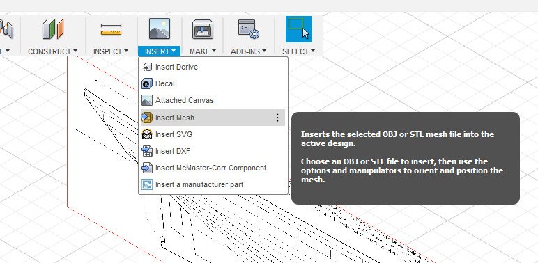

-
Hull modeling with Blender
SardonicMeow replied to SardonicMeow's topic in CAD and 3D Modelling/Drafting Plans with Software
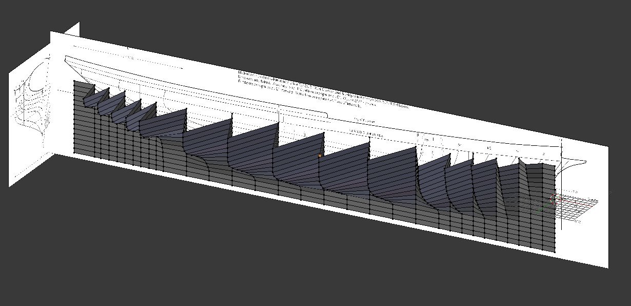
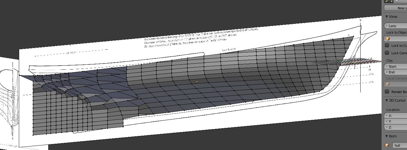
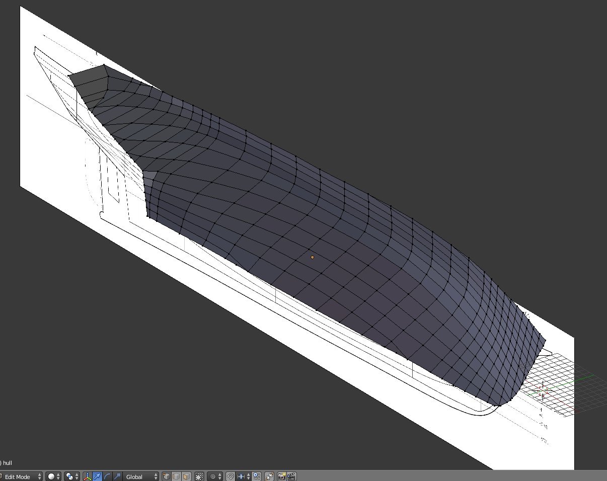
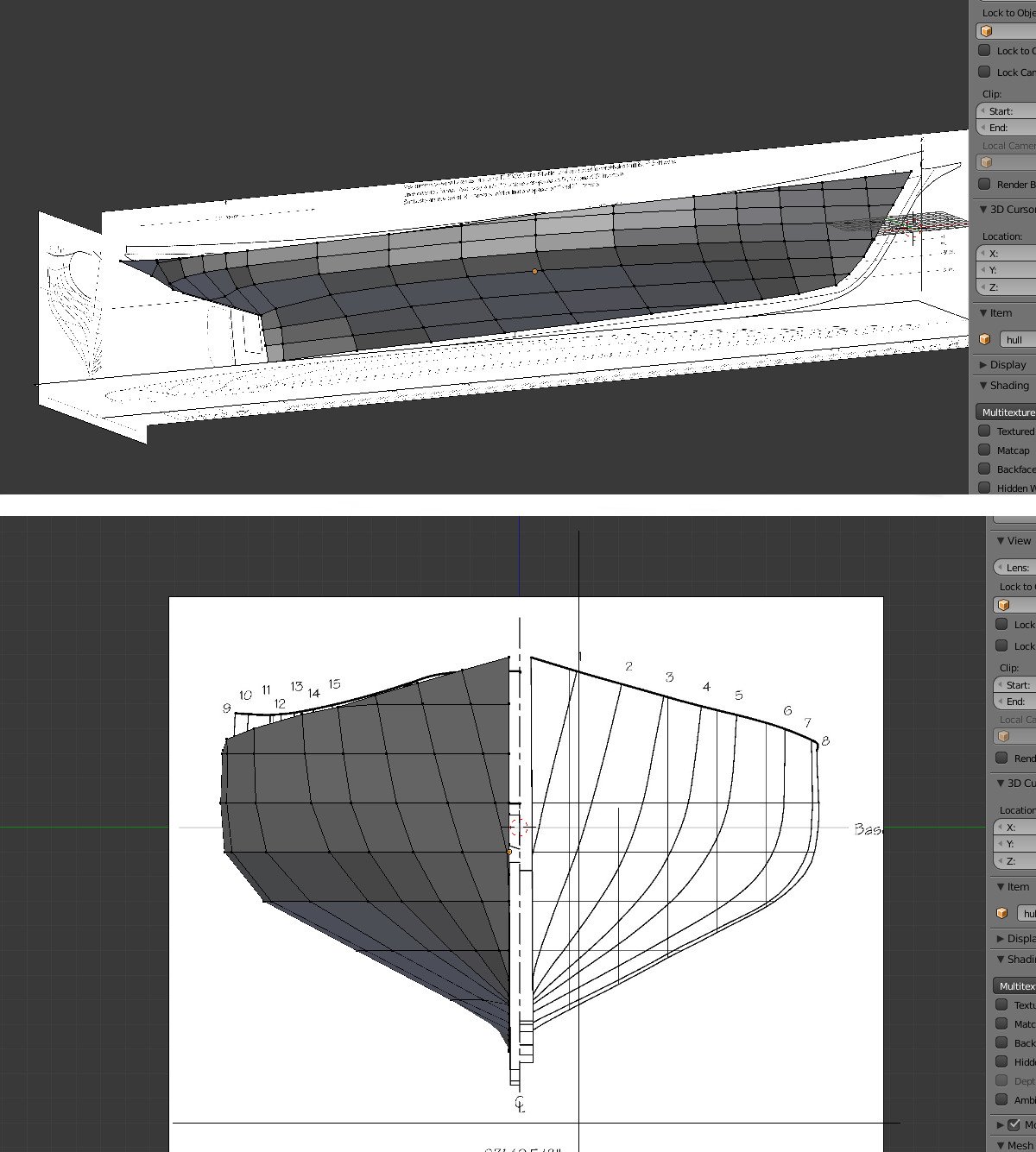
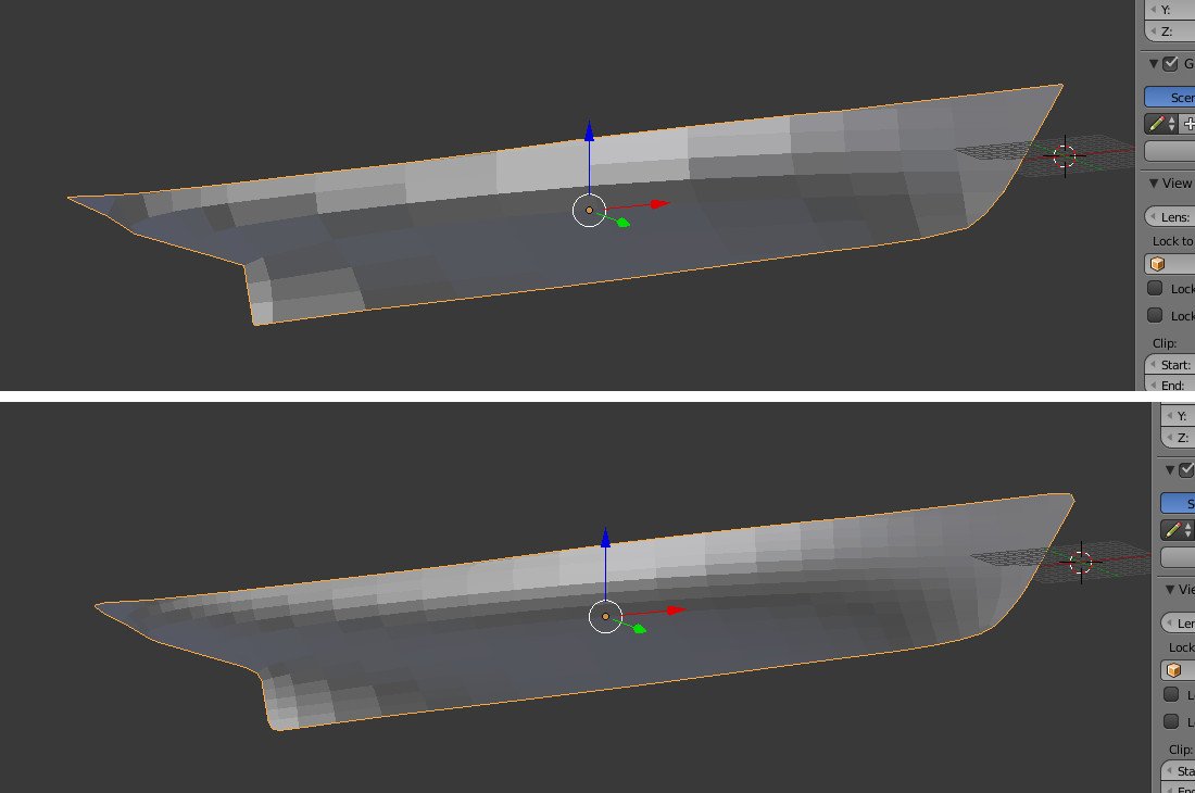
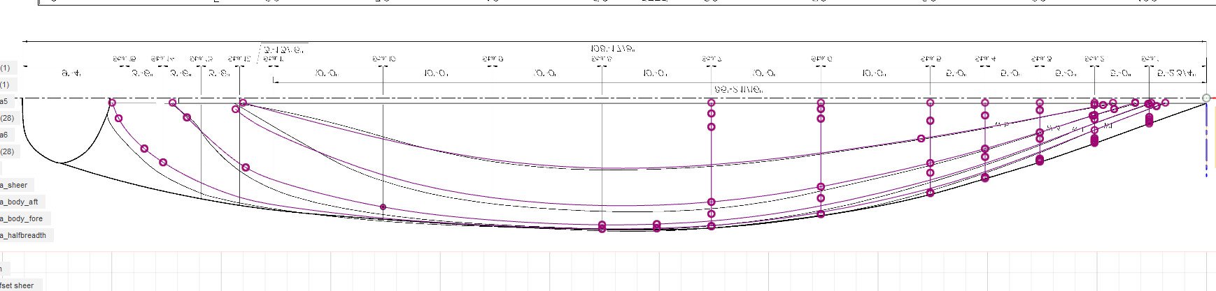
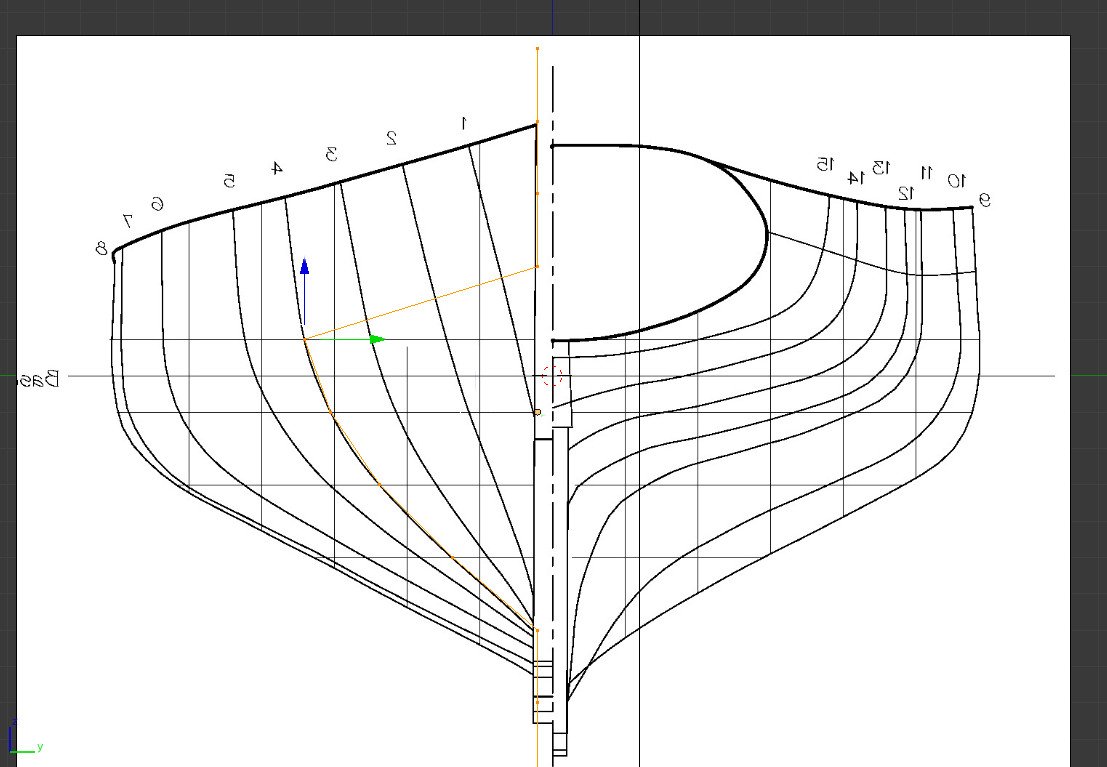
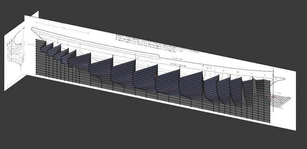
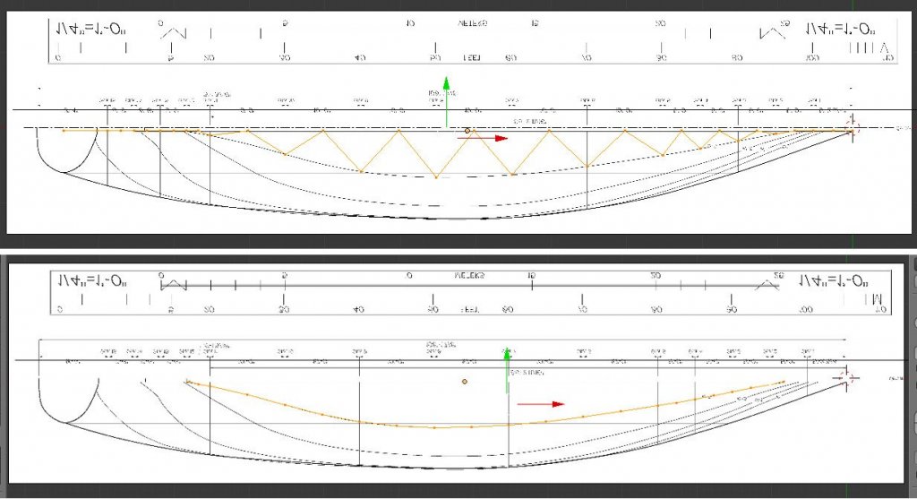
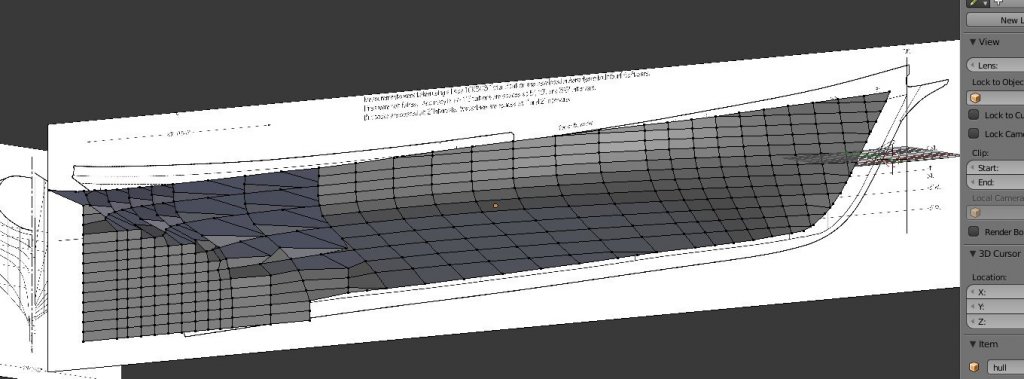
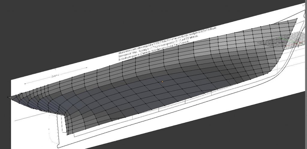
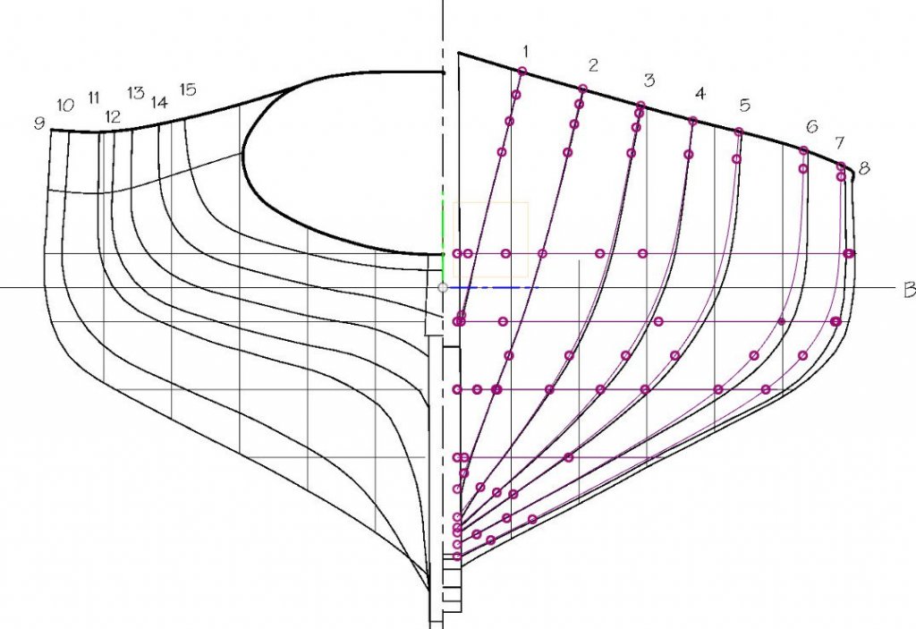
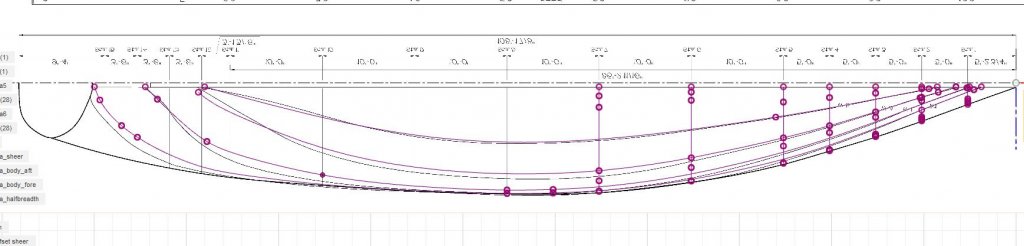
I have gone back to an earlier save. The mesh is still just a flat plane here. This time, I'm going to apply a Simple (not Catmull-Clark) Subdivision Surface right at the start, which gives me four times as many faces. As before, there are vertical lines at each station line and horizontal lines at each water line, but also new intermediate lines. Now I'll work as before, selecting vertical columns of vertices at a station line, hiding all others, and then pulling vertices out from the centerline to lie along the station line. When all the station lines are complete, I have created the USS Accordian. How do I model the curves of the intermediate lines? Well, I can at least find the points where they intersect with the water lines. I select a water line and view it and the halfbreadth view from above. Points already on the water line are from the station line work just done. The points from the intermediate lines can be dragged out to the water line. This is repeated for the remaining water lines. Now it looks like this. Enough points on the intermediate lines are in the correct place to get a good idea of how the line should flow. I go one by one and adjust points on each intermediate line to create clean curves. There is some guesswork and eyeballing here, because there are no plan lines to follow. When the line is done, it's useful to switch from wireframe to solid view and see if the new lines look uniform with the rest of the body. Here it is a little over halfway done. Note that I also adjust the bottom edge of the object to the rabbet line as I go. Two views of the final result. Note in the aft view that this time I carefully constructed the flat transom area. Is this good enough? I'll apply some smoothing, then check the lines in Fusion 360 again. It's much better now, not 100% perfect, but I think I'm satisfied. At the worst spots, it's a deviation of 2 or 3 inches on a ship that's over 100 feet long. Here's a comparison of attempt #1 vs attempt #2. Next time, I'll bring the mesh into Fusion 360 and compare it to my earlier work.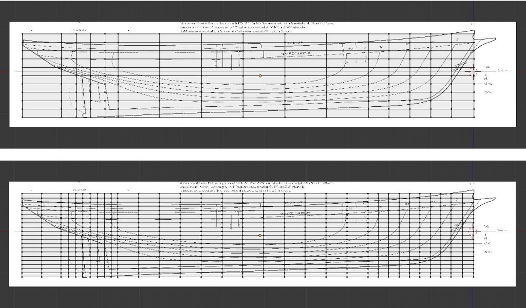

-
Hull modeling with Blender
SardonicMeow replied to SardonicMeow's topic in CAD and 3D Modelling/Drafting Plans with Software
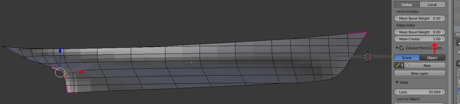
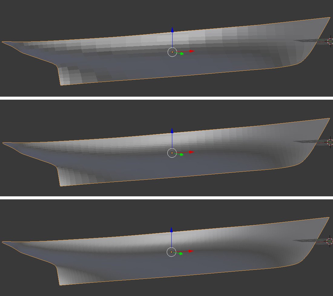
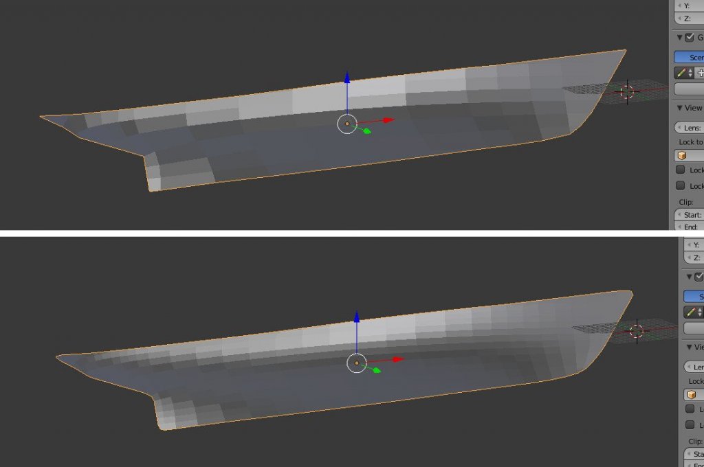
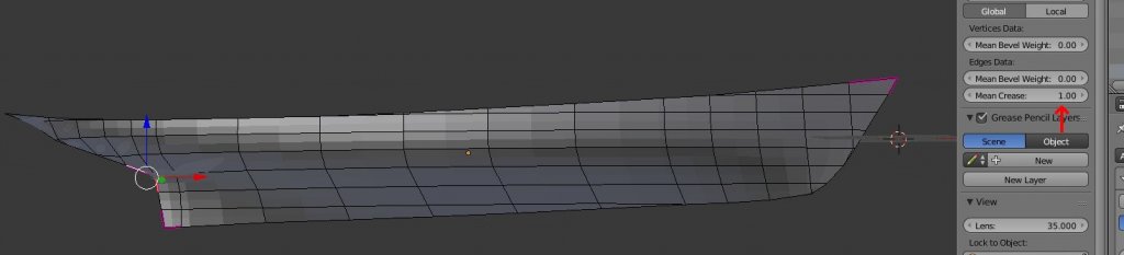
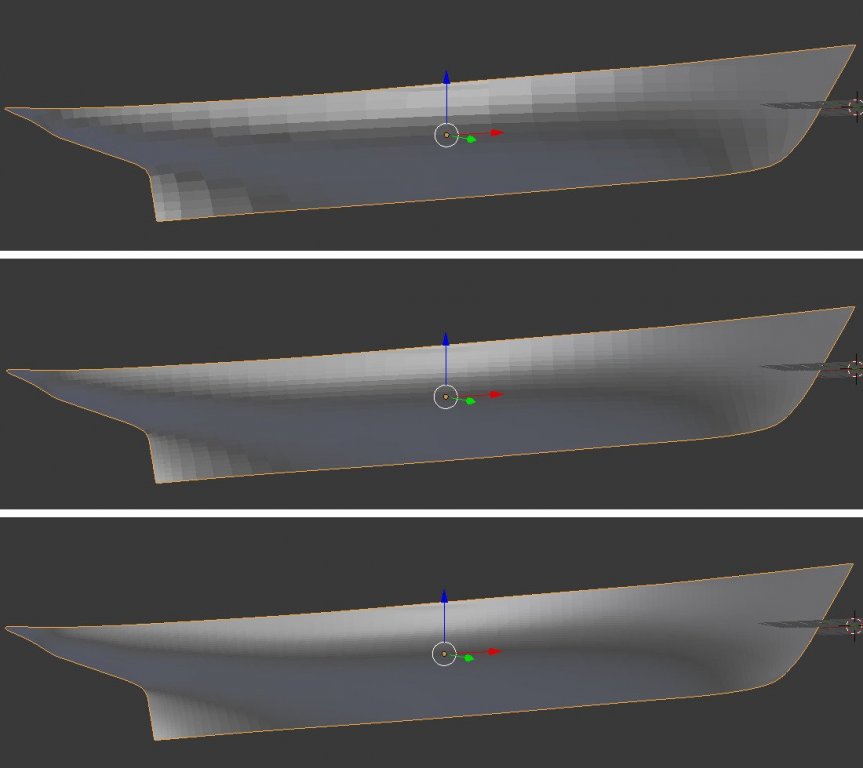
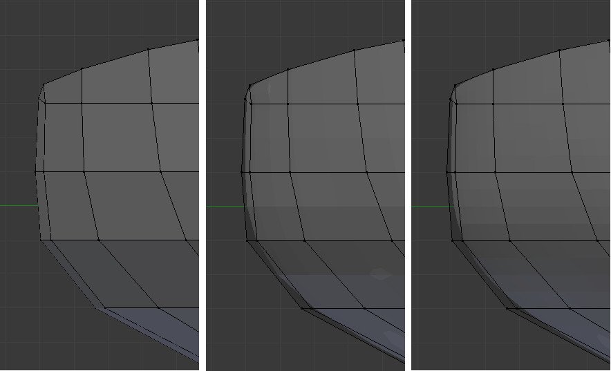
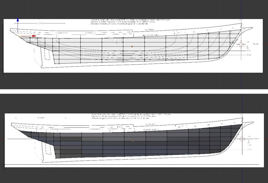
Here are a few views of the state of the mesh. The general shape is there, but it needs more faces in order to smooth things out. (The little info panel at the middle top says there are only 91 faces.) Fortunately, Blender has a great tool for this: the Subdivision Surface modifier. I select the Modifiers icon on the right, which looks like a wrench, then click "Add Modifier" and choose "Subdivision Surface". Modifiers don't take effect until they are applied, and there can be a stack of multiple modifiers which take effect in order. There are two modes: Simple and Catmull-Clark. Simple mode just divides up the faces without changing anything about the shape of the object. Catmull-Clark is where the magic happens. The Catmull-Clark algorithm subdivides the surface, adjusting the new faces to create a smoother surface. The View setting under Subdivisions determines how many subdivisions are actually performed. The image below shows before and after a single level of subdivision. It's looking better. But look carefully, and there is a problem. The tip of the bow is rounded off, as is the aft end of the keel. To fix this, we need to tell Blender not to perform any smoothing at those areas. I go back into edit mode, and at the bottom, switch from vertex select mode to edge select mode. I select the edges that I want to remain sharp, and on the properties panel where it says "Mean Crease" I change the value from 0 to 1. The affected edges are highlighted in a pink-purple color. Now the Subdivision Surface modifier smooths out the hull, but leaves the sharp areas sharp. Just for fun, here are images of one, two, and three levels of Subdivision Surface. Amazing. Incredible. It can't possibly be this easy, right? How close does this mesh match the lines on the plans? I'll import the mesh into Fusion 360 (procedure to be explained later) and plot intersection lines with the station and waterlines. The results are a little disappointing. The curve of the mesh is close at the bow but deviates from the lines amidships. The problem is that Subdivision Surface flattens as it smooths. Here are zero, one, and two levels of Subdivision Surface viewed from the front on the ship. Black lines are the wireframe of the original mesh. From this view, it's clear how the smoothing operation is also shrinking the surface. So much for the miracle of Subdivision Surface. But what if I manually create a mesh with a higher level of detail, matched to the plan lines? Then it won't suffer as much from smoothing. Next time.
-
Hull modeling with Blender
SardonicMeow replied to SardonicMeow's topic in CAD and 3D Modelling/Drafting Plans with Software
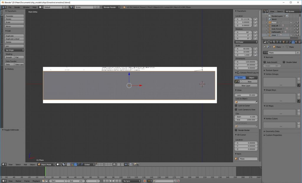
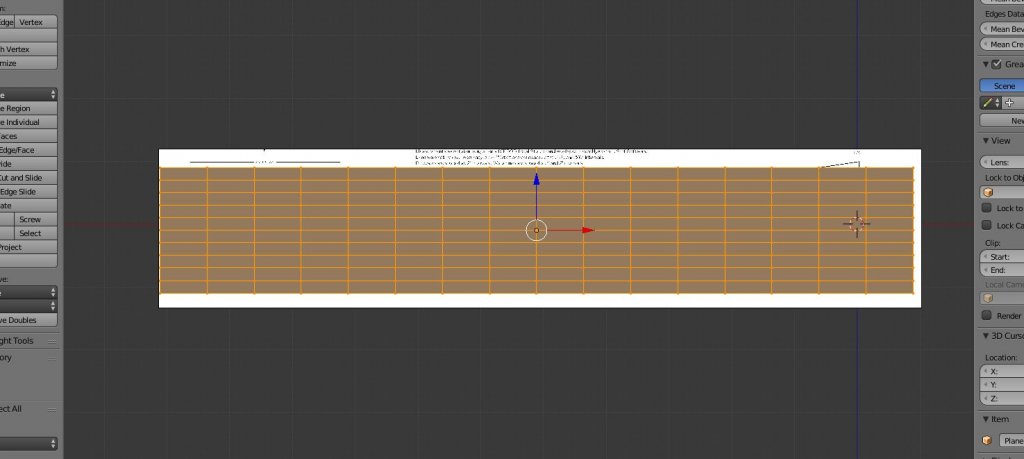
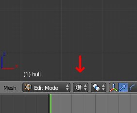
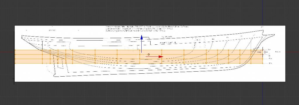
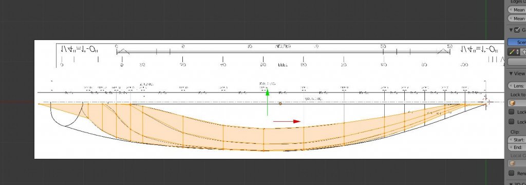
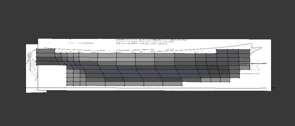
It's time to start creating the hull. Briefly, I'll be creating a plane, subdivide it, then pull out vertices to match the station lines. This will start to form the general hull shape. First, I'll click the eyeball icons next to the reference images to hide them. They are in the way right now. I can hide or unhide them whenever I need them. Then, Shift-A to create a new object, Mesh -> Plane. A new plane is created. It's 2 x 2 units and lies in the XY plane. First I'll rotate it 90 degrees in X. I'll move it -1 in Z to match the width of the keel out from the centerline. Then, I'll type in new dimensions. I want the plane to be larger than the length and height of the hull. It's also convenient for the height of the plane to be a multiple of the distance between waterlines (2 feet, in this case). 120 feet by 20 feet works out well. Next, I'll hit Tab to switch from Object Mode to Edit Mode. In Object Mode, an object is manipulated as a whole. In Edit Mode, the vertices, edges, and faces of an object can be manipulated individually. I'll hit Control-R to do a loop cut. The cuts will be horizontal or vertical depending on whether the mouse pointer is near a horizontal or vertical edge. The mouse wheel can be used to increase and decrease the number of cuts. I'll do 9 horizontal cuts, giving me 10 sections of 2 feet each. I'll do another loop cut of 15 vertical cuts, to correspond to the 15 stations. Because the stations are not evenly spaced, they will need to be adjusted. The control at the bottom left, just to the right of "Edit Mode", changes the display mode. The default is solid, but I need to change it to wireframe so that the reference image can be seen through the object. A few more hotkeys: 'a' toggles between all vertices or none, 'c' brings up the circle selector, a selector of adjustable size which can be dragged across vertices to select them. I'll hit 'a' once or twice to make sure no vertices are selected. Then I'll use the circle selector to select a vertical column of vertices. The selection of vertices will be moved in +X or -X until they line up with a station position. I clear the selection, choose another column of vertices and repeat. In the image below, you can see the original, where the sections are evenly spaced, and the result after moving vertices to match the station positions. One useful feature of Blender is hiding. The 'h' key hides what is selected. Shift-H hides everything except the selection. And Alt-H brings back whatever has been hidden. Here's my procedure at this point. I select the vertices in a vertical column (corresponding to a station). I hide all except those vertices. I switch to the body view (keypad 3), and going from vertex to vertex, I drag each out (using the green Y handle) to touch the station line on the reference image. Halfway done... And complete. To double check, I can select the four rows of vertices which match the waterlines. And view them from above (keypad 7). Looks pretty good. Now to start cleaning things up. First, I'll go and delete all the vertices that are far enough away from the hull that it's clear they are not needed. At this point, I carefully go along the rabbet and sheer line, adjusting the location of the vertices along the edges. Sometimes, vertices will be merged to create triangular faces. Below is the result in wireframe and solid views. At this point, it looks like a hull, but it's still very blocky with lots of straight lines instead of smooth curves. Next time, I'll use the Subdivision Surface modifier to start smoothing out the hull.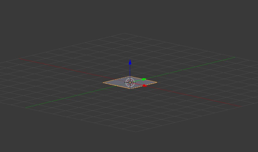
-
Hull modeling with Blender
SardonicMeow replied to SardonicMeow's topic in CAD and 3D Modelling/Drafting Plans with Software
Hi, Stephan. You clearly have much more experience with Blender than me. I'm just a beginner, but I'm sharing this log to document what I've learned. Once I finish my posts, I hope you will let me know if there is a better technique than what I have done. -
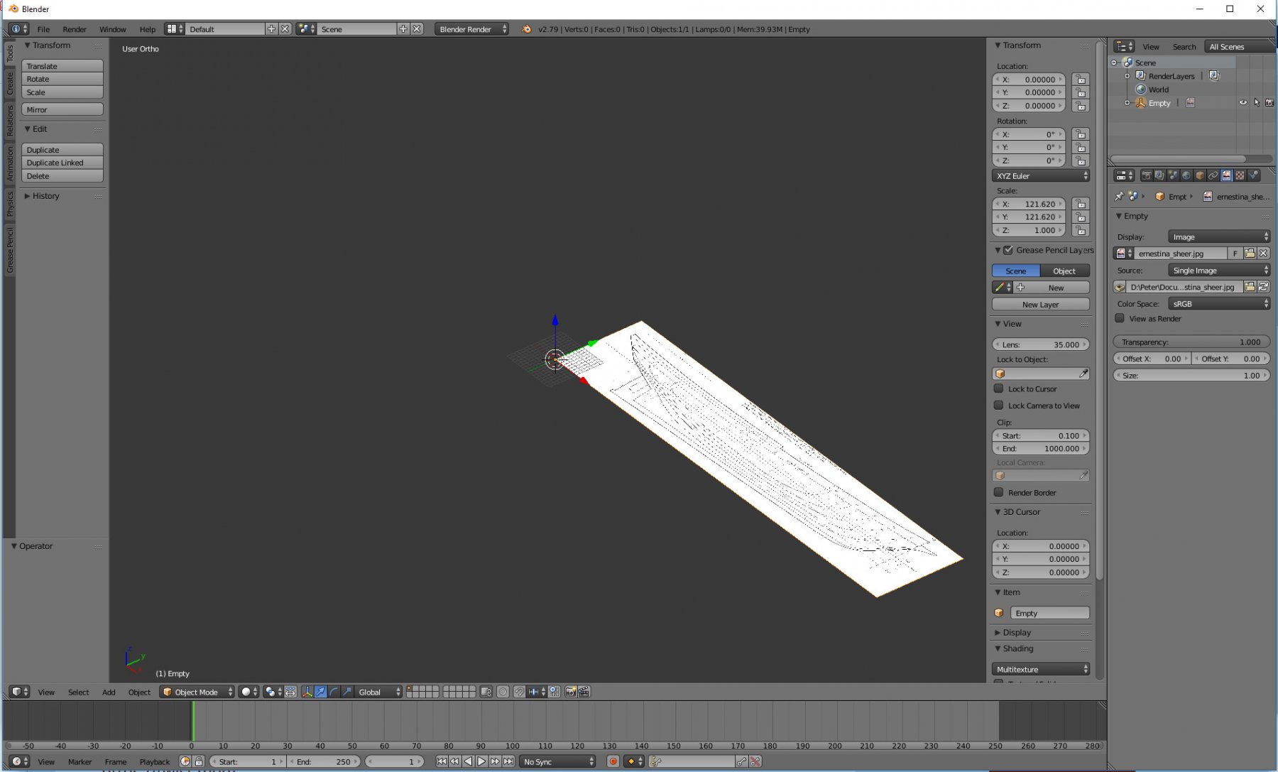
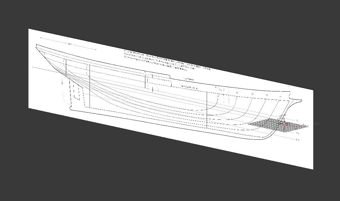
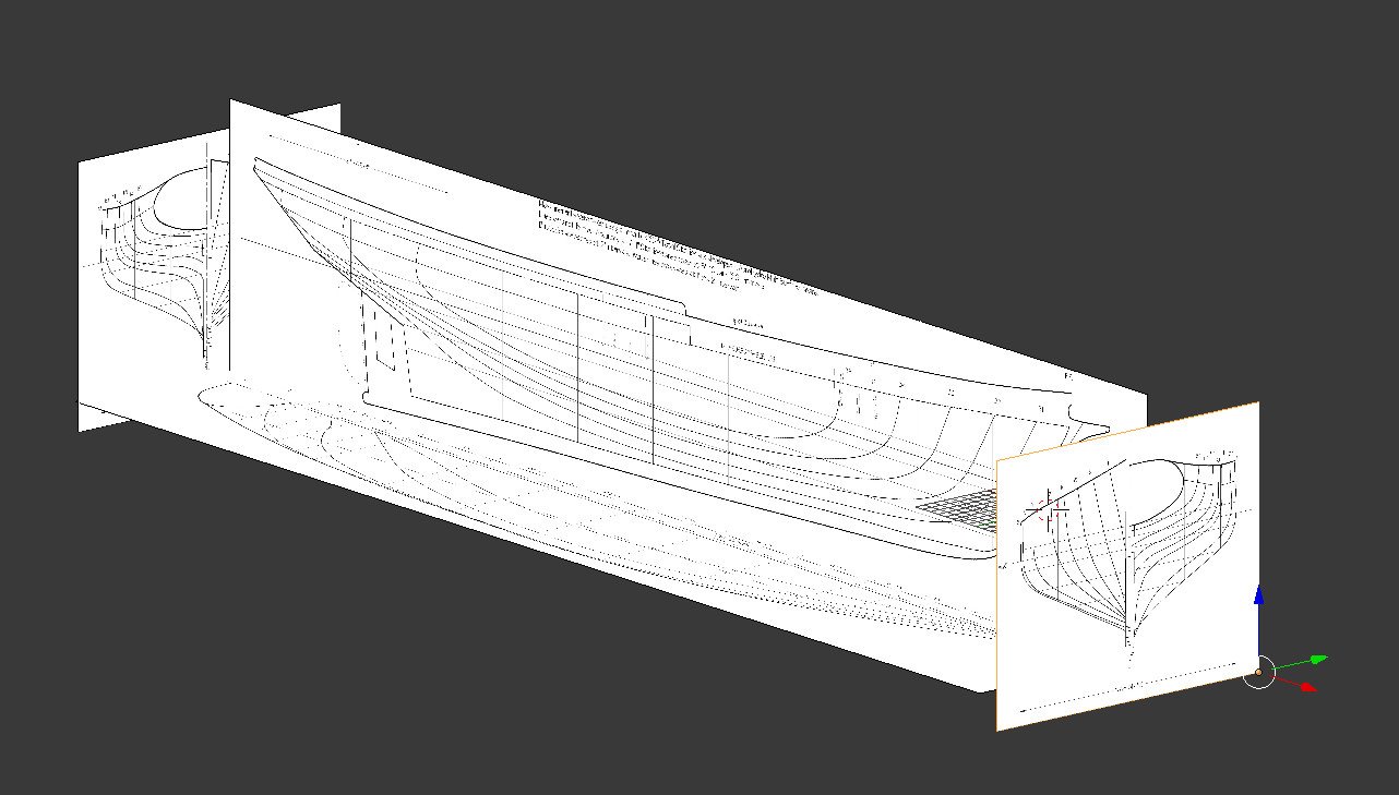
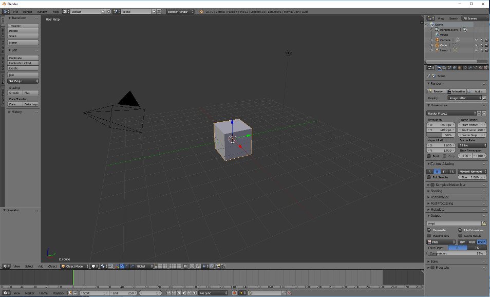
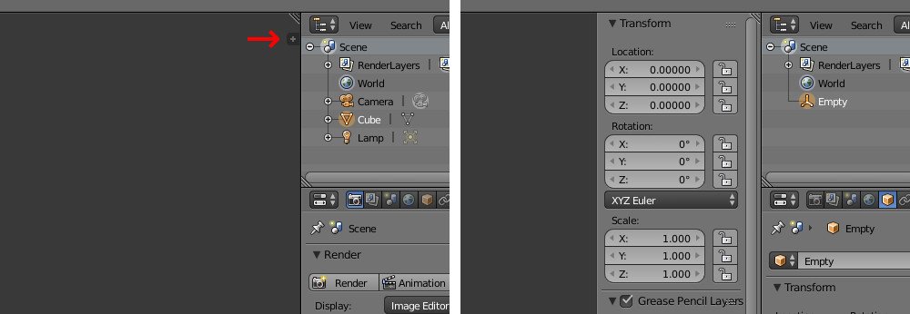
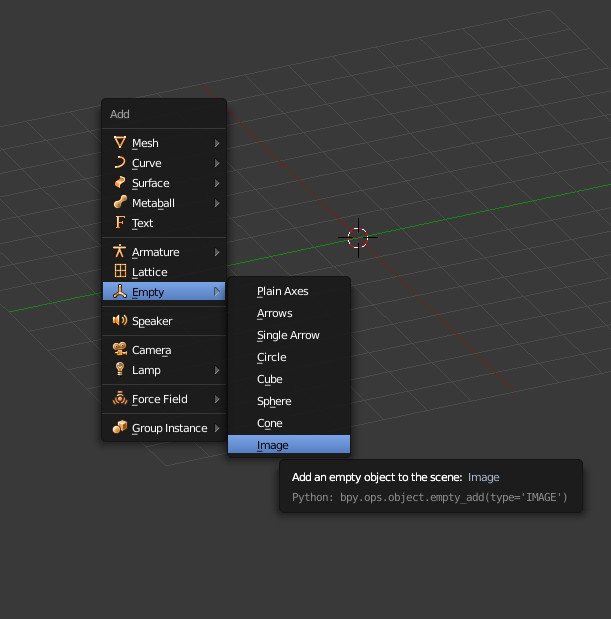
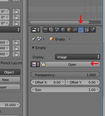
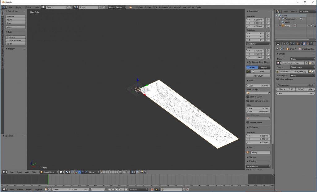
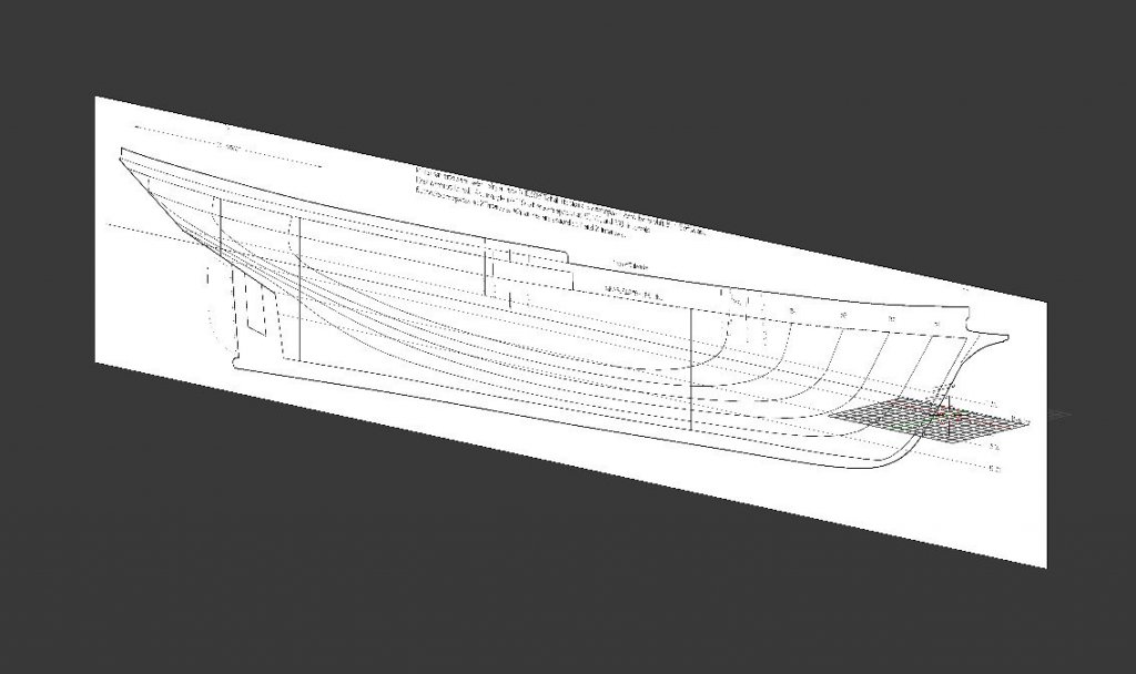
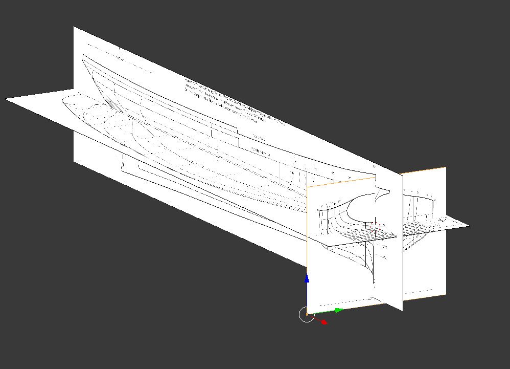
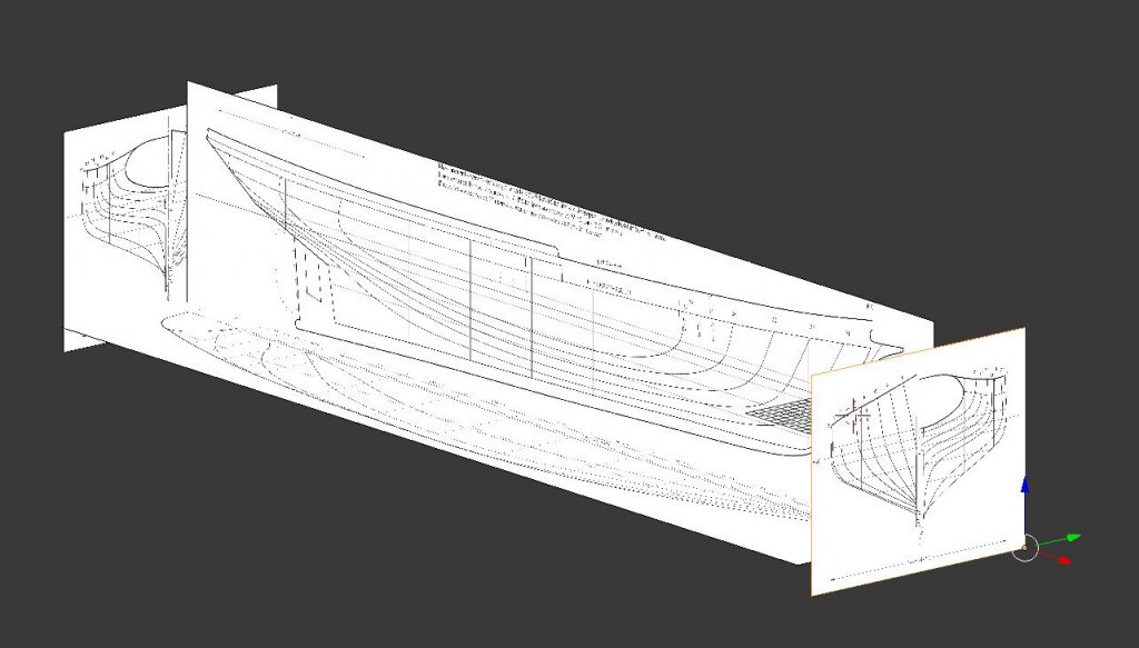
Welcome to the exciting (?) sequel. Previously, I blundered through using Fusion 360 to go from ship plans to a 3D model. This time, I'll be blundering through using Blender instead. Both Fusion 360 and Blender are powerful programs with overlapping features. However, while Fusion 360's strength is parametric modeling, Blender's is modeling meshes. I'll be using a mesh approach in this thread. A note on Blender versions: The current stable release is 2.79. Blender 2.8 beta was released recently. There are significant changes in 2.8, including interface changes, which means someone familiar with 2.7x will have to relearn some things for 2.8x. I wanted to use 2.8, but ran into bugs (since it is still in beta status). Therefore, I will be using version 2.79 here. As before, I'll be modeling Ernestina, because the plans are free and of good quality. Let's start up Blender. There are lots of interface pieces surrounding the 3D viewport in the center. The default scene contains three objects: a camera, a light, and a cube. None of the default objects are needed. Right click to select an object, then hit Delete to remove it. (In Blender 2.8 the default selection is by left click rather than right click. This can be changed in File -> User Preferences -> Input.) Some other initial setup. Keypad 5 toggles between orthographic and perspective views. Perspective is the default on the first startup. I need the view to be orthographic. To quickly switch between different orthographic views, the hotkeys are keypad keys 1 (front), 3 (right), and 7 (top). Keypad key 9 toggles orthographic views: front becomes back, right becomes left, and top becomes bottom. I have found these keys (1, 3, 7, 9) very convenient to switch through the views. The other thing I like to have open all the time is the properties panel. It can be toggled on and off with 'n' or it can be opened by clicking on the little plus sign in the upper right. Now it's time to bring in the images of the ship plans. As with my work in Fusion 360, the 3D origin will be at the intersection of the centerline, the baseline, and the forward perpendicular. The long axis of the ship will be along the X axis. Calculation time. I'll be creating the 3D model in feet, but in other circumstances it may be better to use a scaled measure. (For example, scale measurements down by 1/48 and then model in millimeters or inches.) I have determined previously that the images are 50 pixels per foot. The sheer image is 6081 x 1270 pixels, which makes it 121.62 x 25.4 feet. The forward perpendicular is 5567 pixels (111.34 feet) from the left edge / 514 pixels (10.28 feet) from the right edge. The baseline is 601 pixels (12.02 feet) from the top edge / 669 pixels (13.38 feet) from the bottom edge. The body image is 1450 x 1194 pixels, 29 x 23.88 feet. The centerline is 712 pixels (14.24 feet) from the left edge / 738 pixels (14.76 feet) from the right edge. The baseline is 468 (9.36) pixels from the top edge / 726 pixels (14.52) from the bottom edge. The halfbreadth image is 6000 x 1475 pixels, 120 x 29.5 feet. The forward perpendicular is 5610 pixels (112.2 feet) from the left edge / 390 pixels (7.8 feet) from the right edge. The centerline is 772 pixels (15.44 feet) from the top edge / 703 pixels (14.06 feet) from the bottom edge. The values from these calculations will allow the images to be positioned perfectly into the 3D environment without needing to eyeball anything. In Blender there are two ways to add reference images: background images, and empty objects of type image. Background images display an image as if it were an infinite distance away, and are only visible in the standard orthogonal views (front, back, top, bottom, left, right). Background images are removed in Blender 2.8 in favor of empty objects. An empty object of type image is a rectangular object that can be placed into a scene with an image painted onto it. The empty object can be moved and rotated like any other object. This makes them more flexible than background images. To make empty objects behave like background images, each can optionally be visible only in an orthogonal view. (There are several empty object types, which are "empty" because they will not be included when a scene is rendered. I only care about empty objects of the image type.) To add an object to the scene, click on "Add" at the bottom left or use the hotkey Shift-A. From the menu choose Empty -> Image. The object is added in the XY plane. The properties panel shows its location, rotation, and scale values. At the right, click on the Data button (the icon looks like three axes), then click Open and select the image. Now it's time to resize and position the object. While it's possible to use the mouse to drag handles and manipulate the object, I prefer to type values directly into the properties panel for precise positioning. First, in X scale I enter 121.62 and 121.62 also for Y scale. (Not 25.4 for Y. This is because the object's X and Y acquire the aspect ratio of the image, so both directions need to be scaled the same amount. This is a little counter-intuitive.) Rotate 90 degrees in X. Then it needs to be positioned correctly relative to the 3D origin. I quickly figure out the values I want are -111.34 in X and -13.38 in Z (using the distances from image edges I found earlier). I can set the image transparency to .5, hit keypad 1 for orthographic side view, then zoom in and confirm that the axes line up perfectly with the lines on the image. The other images are added similarly. I can zoom in, pan around, and confirm that various lines match up. However, this arrangement isn't practical. Instead, I'll move the images out so that there will be empty space where the hull will be created. Also, I'll duplicate the body image and flip it 180 degrees so that the station lines on the opposite side can be used. And that's a good stopping point for today. Next time, I'll start to model the actual hull object.
-
Nice work, Reed. Here is a nice video featuring the owner of Wye River Models. His passion about preserving the heritage of Chesapeake Bay watercraft comes through. For lots of skipjack pictures, the best site is The Last Skipjacks Project. Click on the skipjack list, choose a boat, then click on the More Photos link. There are multiple pictures of nearly every one listed.
- 82 replies
-
- 6
-

-
- skipjack
- wye river models
- (and 2 more)
-
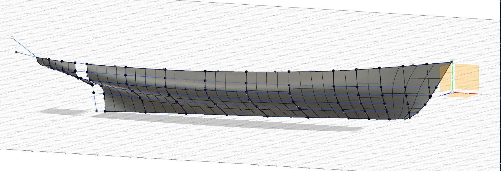
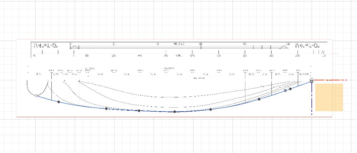
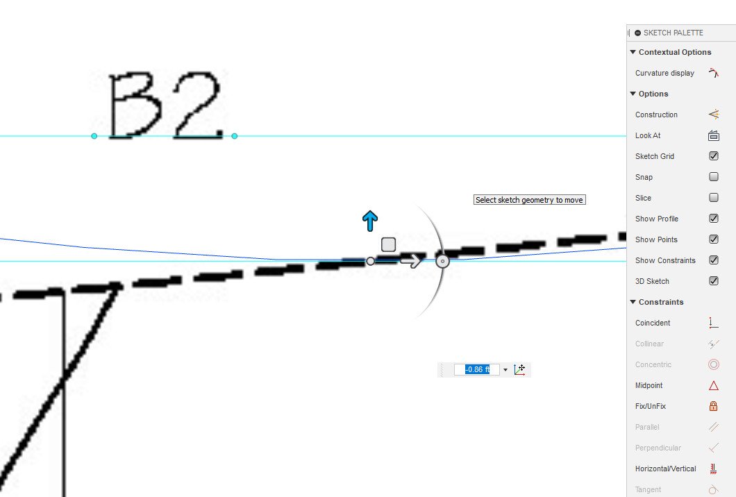
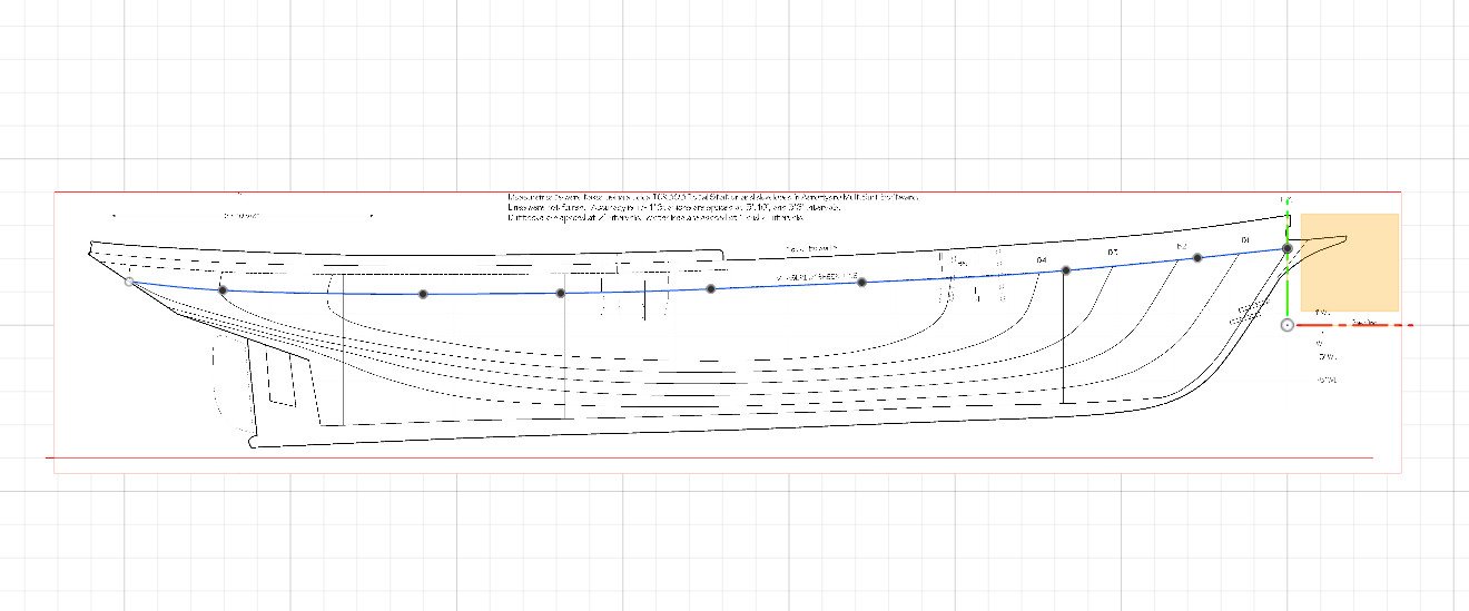
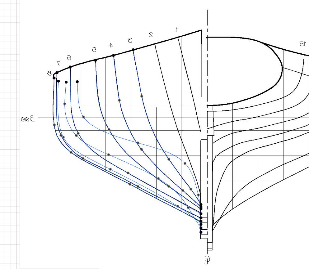
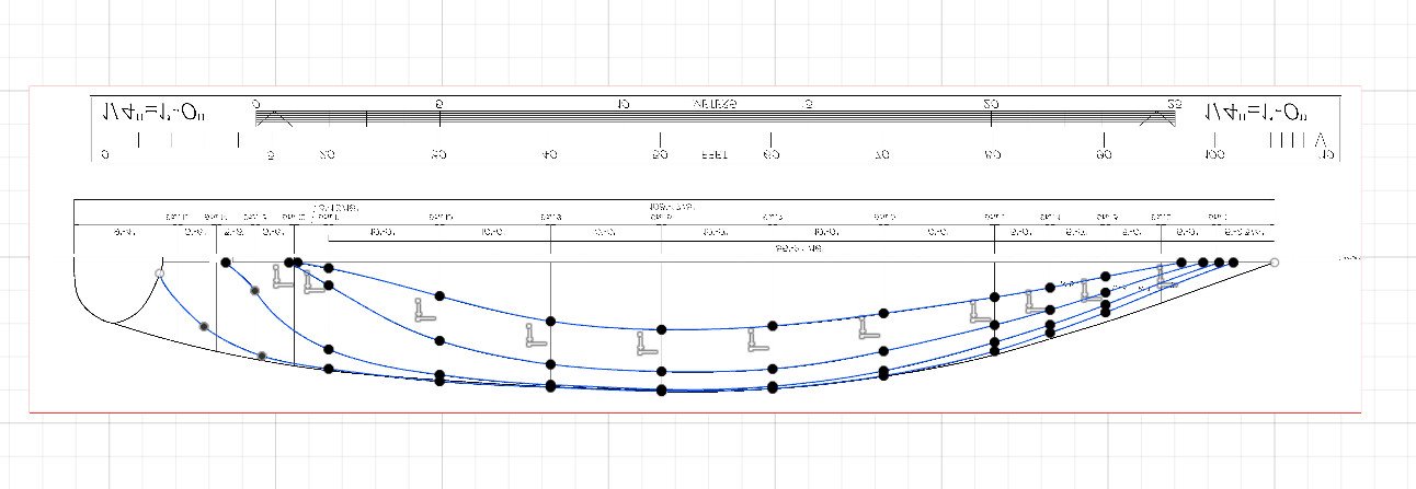
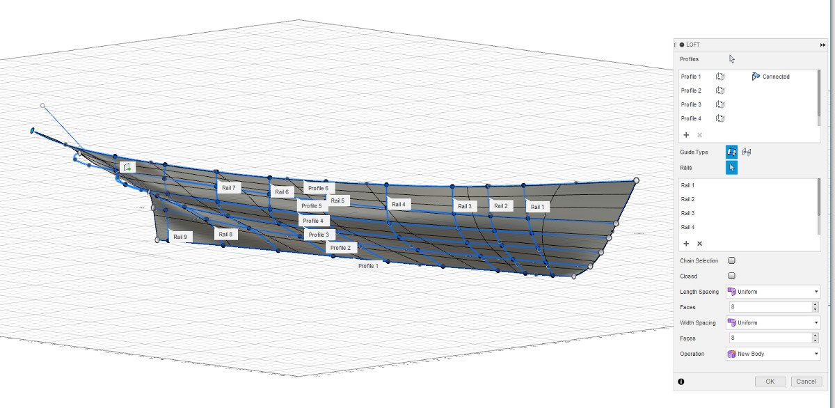
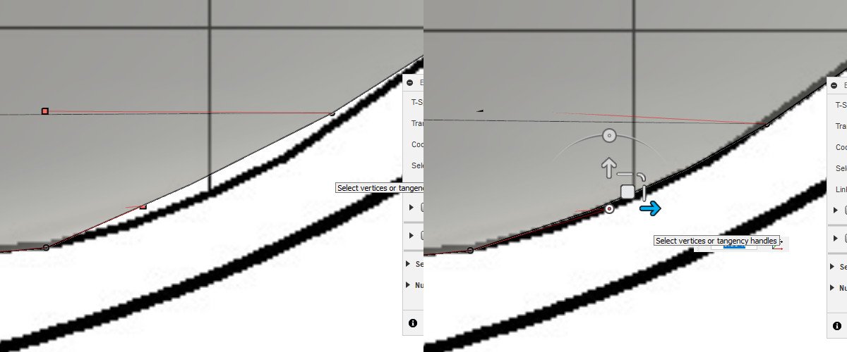
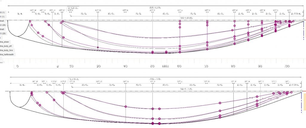
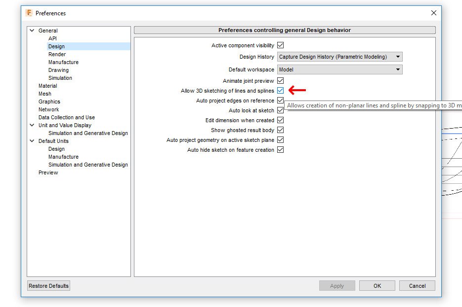
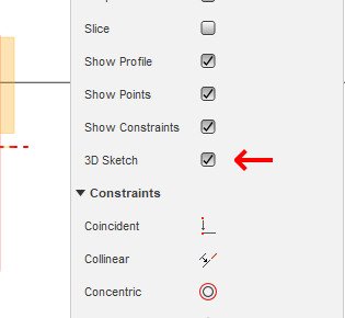
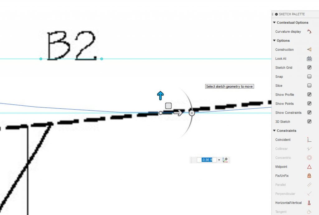
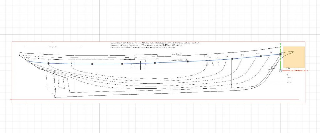
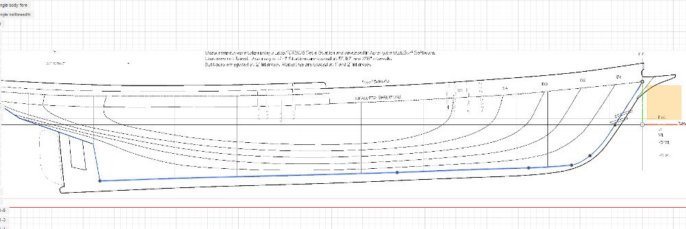
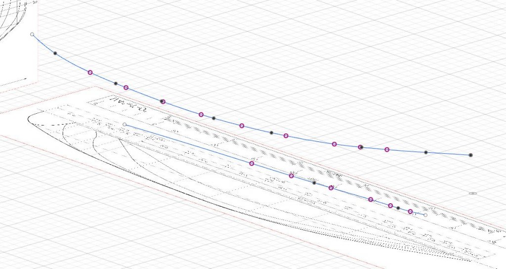
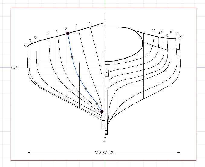
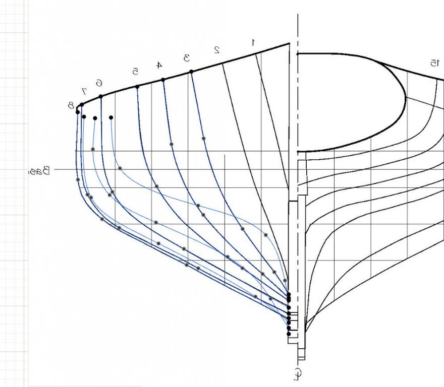
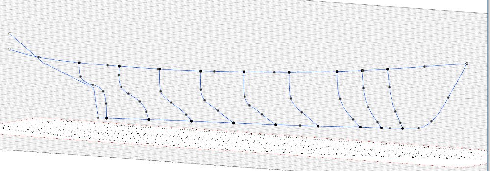
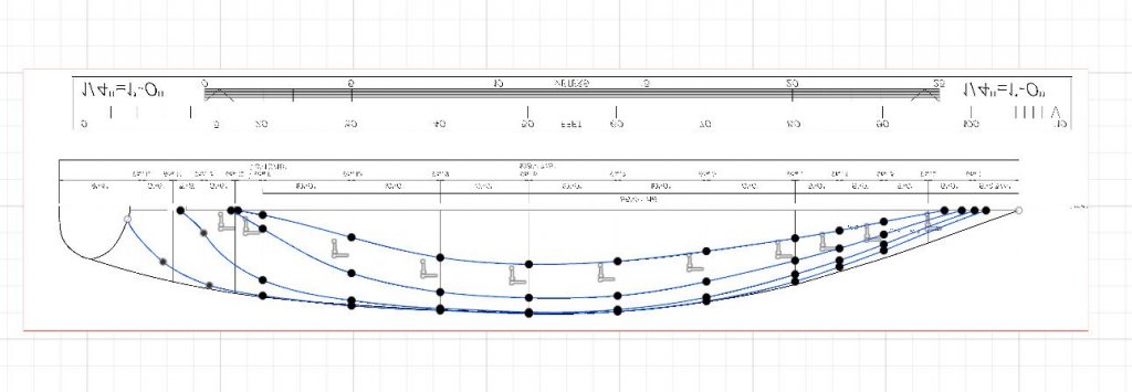
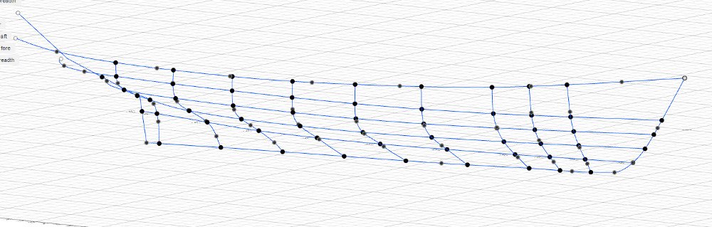
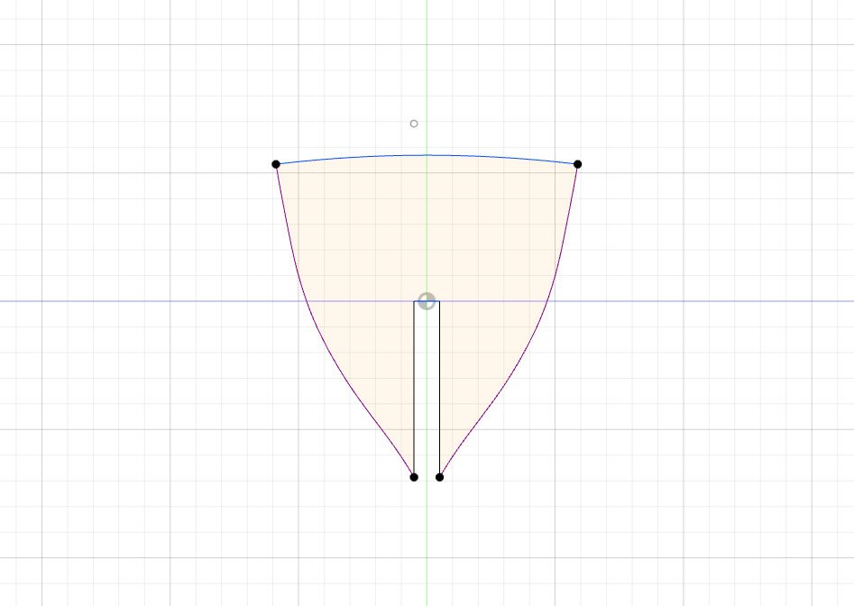
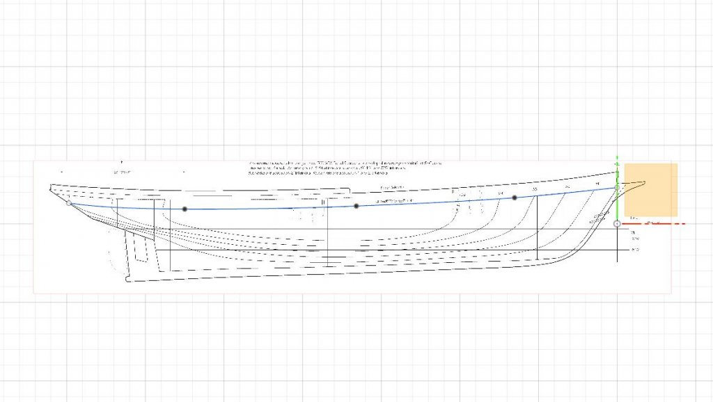
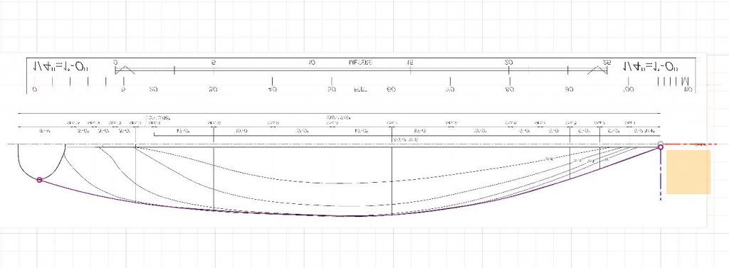
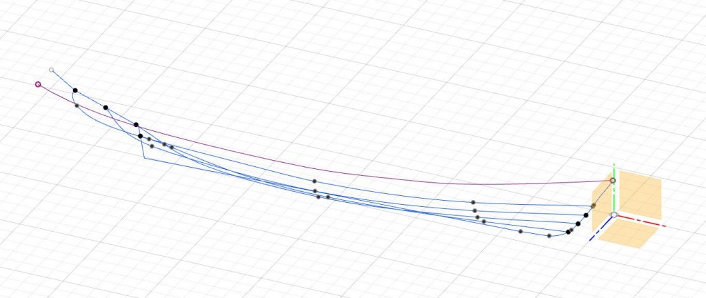
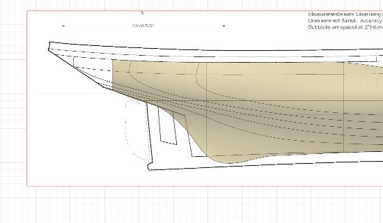
Here we go with try number two. It's a big update today. First of all, in an earlier response, I described a method for creating a curve which bends in 3 dimensions using the intersection curve feature. However, I found that Fusion 360 limits what can be done with this sort of "derived" feature. I could not use it as a profile in a loft, and when I tried to perform further intersection operations using the curve, it would sometimes work and sometimes fail. EDIT: If a "derived" feature, which displays in purple, can't be used for some operation, there is a way to change it into a regular feature. Edit the sketch, then right click on the feature and choose "Break Link". The feature will turn blue. The good news is that there is a better way! Here is the secret. First, go to the Preferences and under General -> Design, look for "Allow 3D sketching of lines and splines". Make sure it is checked. Now start a new sketch. I am going to draw the sheer line again. I start the sketch in an offset plane parallel to the ground plane. I use a fit point spline and create the curve as viewed from above. In the sketch options dialog, make sure "3D Sketch" is checked. With 3D sketches enabled in the preferences and the 3D sketch option turned on for the sketch itself, the curve can now be manipulated in 3D. I switch to a side view. I right click on a control point, choose Move/Copy, and adjust the point up or down as needed. I am careful not to move the point in any direction other than up and down, because that will change the flow of the curve as viewed from above. Once the control points are moved, the handles of each need to be adjusted so that the shape of the curve is correct in the side view. And that's it. Now to keep going. I found that lofting using water lines as profiles for the loft, and station lines as rails, works best. In my original post I used Patch, which creates a body that cannot be modified further. This time I'll be using the Sculpt environment. During some failed attempts, I found that I was confused by those parts of the water lines which overlap on the halfbreadth plan, resulting in curves that were too far in or out. To fix this, I will use the intersections of the station lines with the water lines to find exactly where they go. As I have mentioned before, when lofting in Fusion 360, every rail must touch every profile. To ensure this, my procedure will be as follows: 1. Draw the sheer line (already done, see above) and a line at the top of the keel. These will be the first and last profiles in the loft. 2. Find the intersection points of each station plane with the sheer and keel lines. These will be the start and end points for each station curve. I will only draw the stations which intersect with all the water lines, so some stations far forward and far aft will be skipped. 3. Find the intersection points of each water line with each station curve. Draw the water line curves by passing through each intersection point. 4. Loft the body surface going from keel to water lines to sheer, using the station curves as rails. For the keel / rabbet sketch, I have created an offset plane which comes out from the center line by 1/2 the thickness of the keel. I start a sketch on this plane. This sketch consists of several curves and lines which trace the line from stem to keel to sternpost to transom. However, while there are several components to this sketch, only the line along the top of the keel will be used in the loft. I will be drawing stations 3 through 11, because these are the ones which intersect with every water line. For each station, I select the appropriate offset plane, then go to Sketch -> Project / Include -> Intersect. I select the sheer line and the keel line (purple dots appear at the intersection points), then Ok and Stop Sketch. This is repeated for each station. Once the intersection task is complete for each station, it's time to actually draw the station lines. I select the offset plane for a station and start a fit point spline. I draw the curve of the station, starting and ending the curve on the intersection points (they appear black with a purple outline here). This process is repeated for each station. Again, I chose to skip the forward-most and aft-most stations. Here's what we have at this point. Now I'll find the intersection points with the water lines. I select a water line offset plane and then choose the Intersect operation. I click to find an intersection point at each station, as well as points on the stem curve and in the stern. This image shows the intersection points (purple circles) for all four water lines. To draw each water line, it's simply a matter of starting a fit point spline in the correct water line offset plane, and connecting the dots. Now that we have all the necessary lines, and are confident that there are intersection points where they are needed, it's time to loft. To enter the Sculpt environment, I click on the purple cube. Then under Create I choose Loft. I click on the keel line, then each water line moving upwards, and then the sheer line. Then I click to choose rails, and select each station line. (There was noticeable slowness while selecting each rail.) I guessed about the spacing settings (8 faces in each direction). The form is... not too bad? It's smooth in the front, but it a little wavy aft. In the Sculpt environment, all the vertices, edges, and faces can be moved around to refine the shape. I am just starting to learn how to work with a form in Sculpt. But, as a simple example, you can see here how I moved one vertex to adjust the shape of the bow to match the line on the plans. I exit out of Sculpt, and create a mirror of the surface. It's starting to look like an actual ship. Now let's do something with it. By finding the intersection of the surface with any plane I choose, I can create my own lines plans with water lines / buttock lines / station lines wherever I choose. Here I have created an offset plane near the bow. The results of the intersection operation are new station lines at a location of my choosing. Continuing to work on the same sketch, I add a notch and a curve for the cambered deck. Now I can right-click on the sketch in the browser at the left and choose "Save as DXF". And that file can be imported into laser cutter software. Repeat for multiple bulkheads, and you're on your way to making a plank-on-bulkhead model. (At least, that's what I hope to do eventually.) Thanks for following along! I hope that others who are using Fusion 360 will share their experiences.


-
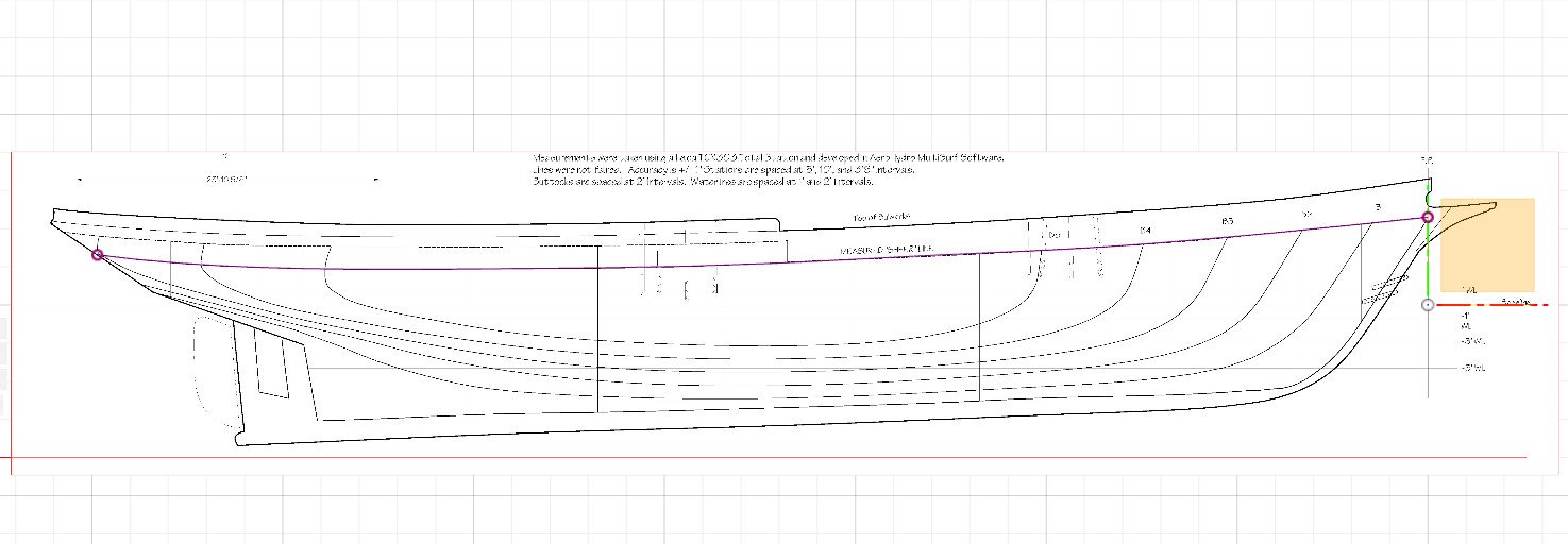
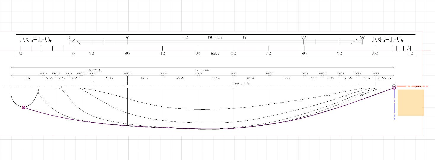
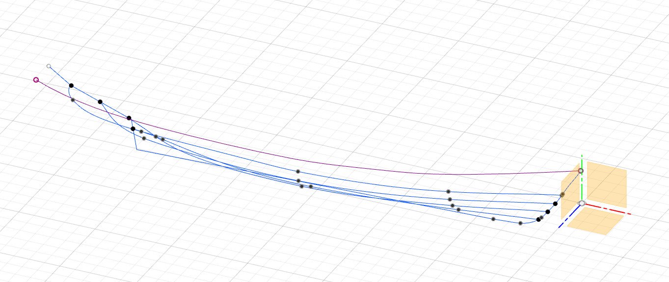
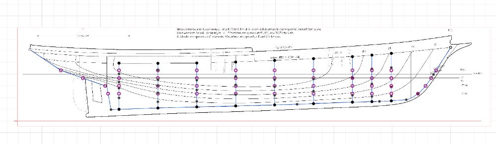
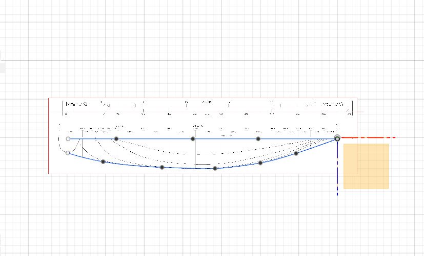
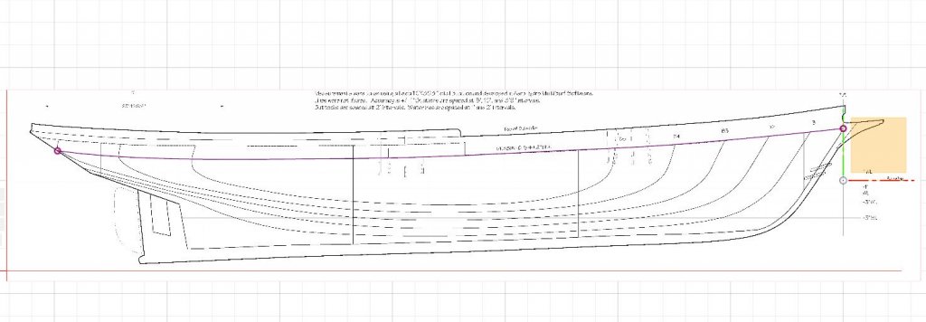
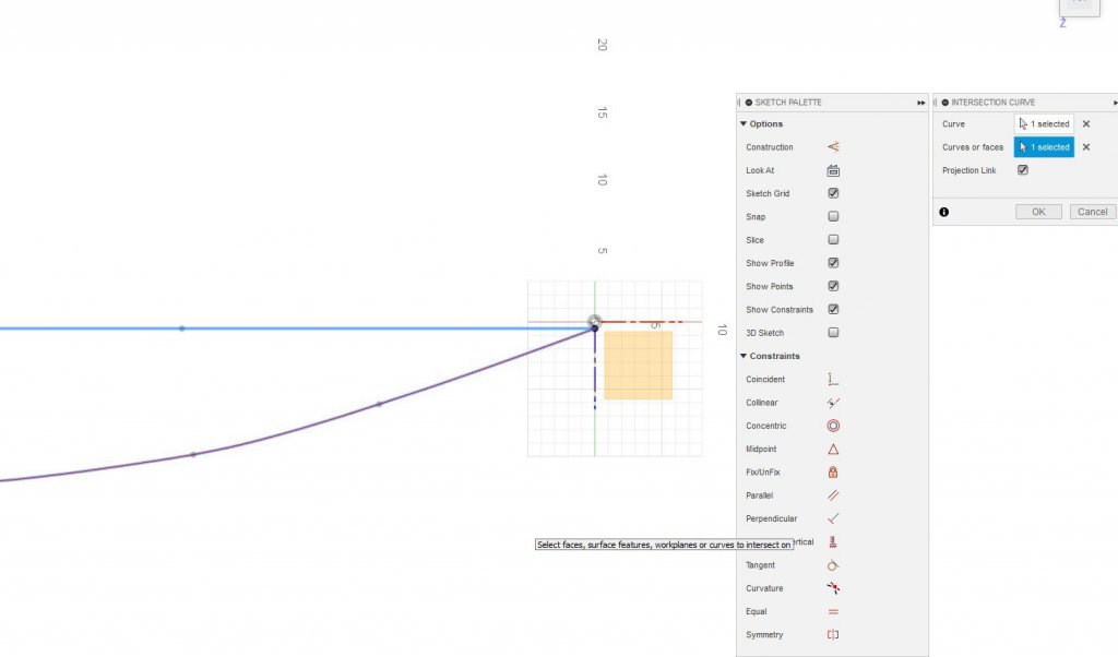
Mark, I may have achieved what you want in Fusion 360. On the Ernestina plans, there is a line identified as the "measured sheer line". Unlike other plan lines, this line is curved in every view. To start, I used the intersection of three offset planes to locate the point at the bow where the line starts. I then started a fit point spline sketch in a plane parallel to the side view and created the curve shown below. Let's call this curve A. Next, working on a plane parallel to the top view, I created a second curve following the sheer line as viewed from above. Let's call this curve B. From this view, curve A looks like a straight line. Both curves share a starting point at the bow. Here are the same two curves viewed from the side. In this view, curve A is curved and curve B appears straight. Now it's time to combine them into a single curve. I go to Sketch -> Project / Include -> Intersection Curve. First I select a plane for the sketch. As far as I can tell, it doesn't matter which plane I use, but I used the offset plane where curve B lies. Next, the tool pops up asking me to select the curves. I select curves A and B and hit Ok. Here is the new sketch curve, displayed in purple, from the side. And from the top. As you can see, it curves in several directions. Here it is along with sketches for the rabbet line and water lines. Unfortunately, Fusion 360 does not allow me to use it as a profile in a loft. However, I may be able to use it as a rail if I am lofting using the section curves. I plan to try that next.
-
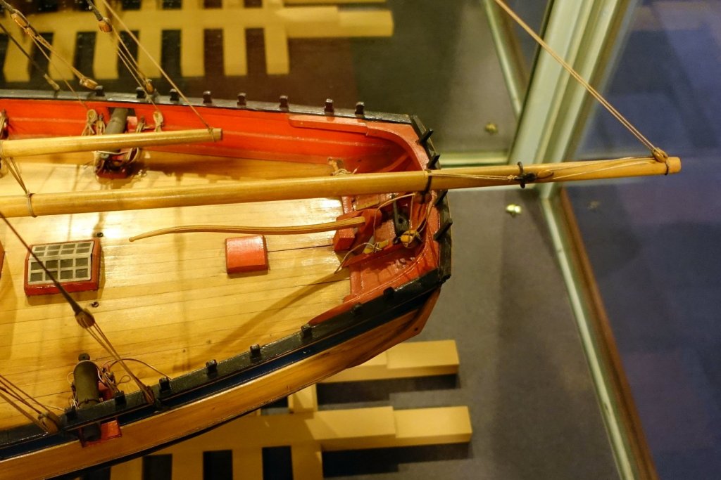
Here is a picture I took last fall of the Sultana replica showing that feature in more detail. On the replica ship, that is where the life vests are stored. I'll let someone else respond as to whether or not hammocks would have been there on the historical ship.
- 360 replies
-
- 1
-
-
- sultana
- model shipways
- (and 1 more)
-
Mark, thanks for mentioning that video. Here is a link to it if anyone else is interested. It made it clear that I was going in the wrong direction by using Patch to create the hull surface. I should be using Sculpt / T-Spline, which is much more powerful. I am now learning what I can about it. I'm not clear what you're asking regarding projection / intersection. In what I have done so far, all of my curves have been drawn in planes which are parallel to the primary XY, XZ, YZ planes. In your drawing it looks like you have a curve in the XZ plane and a target plane that is at an angle to the XZ plane and you want to project that curve onto the target plane. That's not something that I have done. What I did was create waterline curves in the waterline planes, then I found the points where each station plane intersects each waterline curve. After that, drawing in a station plane, I drew the curve for a station, making sure the curve would pass through the intersection points. I can post a more detailed explanation with pictures if that would be of value.
-
I went looking through pictures I took of the Cheerful / Surly model in the Rogers Collection at the US Naval Academy museum, hoping to find something helpful. However, on that model there are no lockers or heads or anything in the stern. Oh well.
- 574 replies
-
- 4
-
-
- cheerful
- Syren Ship Model Company
- (and 1 more)
-
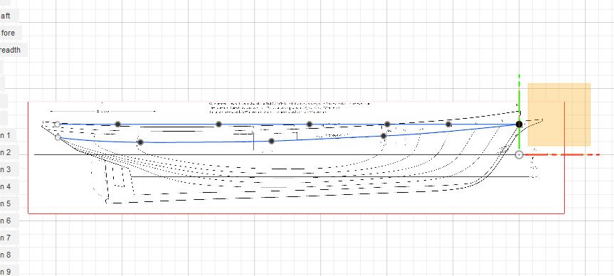
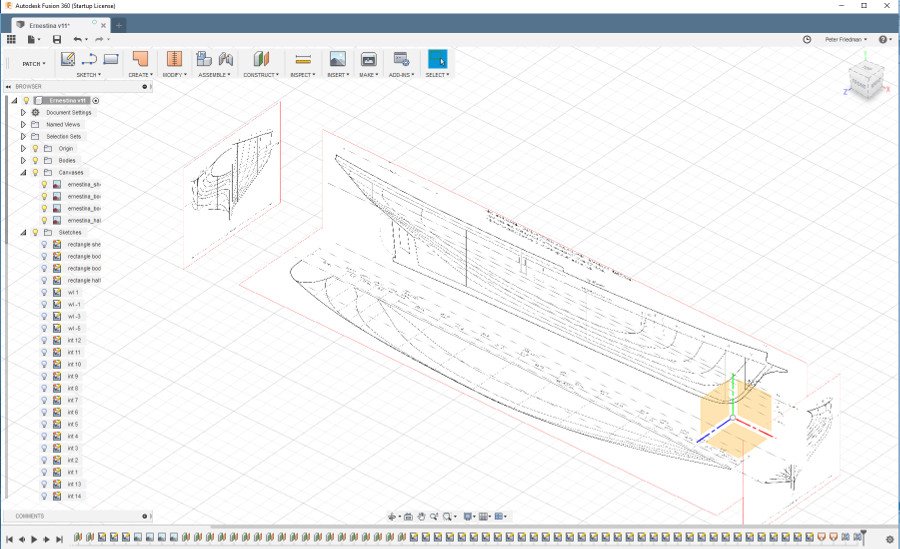
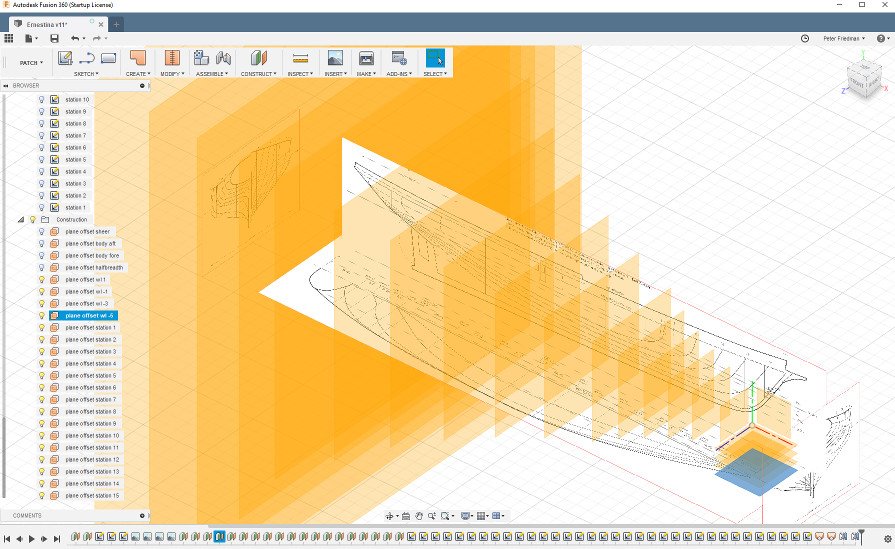
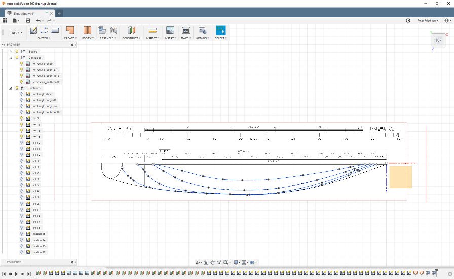
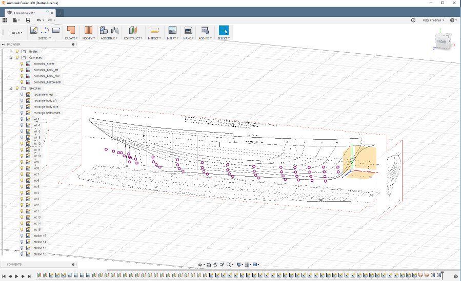
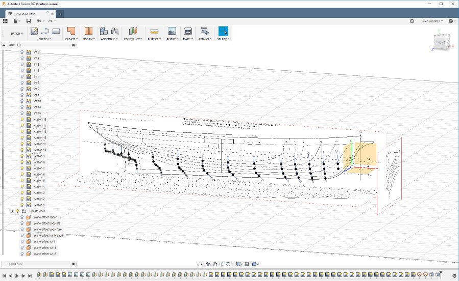
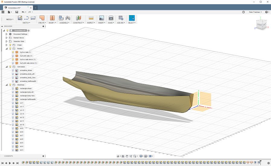
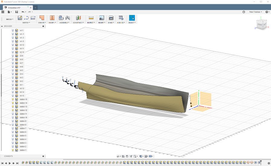
I have been slowly learning Fusion 360 with a goal of accurately modeling a hull as a 3D object based on lines plans. I haven't been completely successful, which is why I titled this "an attempt". I am posting with the hope that individuals with more Fusion 360 than me can tell me if I'm headed in the right direction with my approach, and if so, how to proceed from here. Thanks in advance for having a look. For this exercise, I have used the plans of the schooner Ernestina, which can be freely downloaded from the Historic American Engineering Record at the following link: http://www.loc.gov/pictures/item/ma1719.sheet.00018a/ I chose to use the Ernestina plans because they are very clean and accurate, requiring little extra work to make them usable. I cropped each of the views and saved each to a separate file. Then each plan was brought into Fusion 360 as a canvas, as shown below. To ensure correct scale, I calculated how large each image should be in the 3D environment, I created rectangles of the correct dimensions, then placed the canvases onto those rectangles. That put the images into the 3D world at the correct size. The canvases were positioned so that the world origin point was at intersection of the baseline, center line, and forward perpendicular. Next I created offset planes for each waterline (4 total) and each station line (15 total). It is a mystery to me why Fusion 360 displays larger and larger planes the further each offset plane is from the origin. I created fit point splines for each waterline, drawing each on the appropriate waterline offset plane. I learned early on that if I want to use the Loft operation with Rails, it is a requirement that every profile being lofted must intersect with every rail. To make sure this would happen, I would select an offset plane and use Sketch -> Project / Include -> Intersect to create a set of points where the offset plane intersects with the waterlines. This was repeated for each station offset plane. The intersection points are visible as the purple circles in the image below. Note that one forward station and the four aft-most stations do not intersect all 4 waterlines. Then I drew a fit point spline for each station, making sure to touch each intersection point along the way. Finally it's time to loft. I switched from Model mode to Patch mode, then went to Create -> Loft. The image below shows the result of lofting all 15 sections without using rails, then creating a mirrored body for the other side of the hull. For this particular hull, the shape is pretty good, but I know that for other hulls the incorporation of the waterlines and/or buttock lines and/or diagonal lines is required to achieve an accurate hull shape. So in order to incorporate the waterlines, I need to loft with rails. I can only use the stations which completely intersect with every waterline, so some must be skipped. The result of lofting with rails is below. And that's as far as I can get. My questions: Am I following a good approach, or are there features of Fusion 360 that I have overlooked that would make this easier? How do incorporate the station lines that couldn't be used in the loft + rails? How do I close up the shape at the bow? How do I force curved edges of a body like the one below into straight lines that can bend at sharp angles? Thanks again for any insight.
-
Nice work. How do you plan to handle the centerboard? It looks like it slides down to one side of the keel. Will you plank the hull first, then cut a hole for the centerboard? Or do you create the hole now and add the frames around it?
-
Earlier in the year, when I visited the Chesapeake Bay Maritime Museum, I purchased a copy of Chesapeake Bay Schooners by Quentin Snediker and Ann Jensen. It contains lots of historical information about these schooners, many pictures, and a handful of plans. It may be useful for this project of yours. I think "longhead" refers to how, at the bow of Chesapeake schooners, pungies, bugeyes, and skipjacks, the stem extends forward and narrows to a sharp point, with traditional painted trailboards integrated on either side.
-
I remember recently seeing a remarkable stop motion video of the building of this kit. Happily, I was able to find it again: Stop motion build of AL Fokker Dr. I by Tom Grigat Maybe it will even help with some of your assembly questions.
- 141 replies
-
- 10
-
-
Fusion 360
SardonicMeow replied to Williamo's topic in CAD and 3D Modelling/Drafting Plans with Software
Excellent. Thanks. -
Fusion 360
SardonicMeow replied to Williamo's topic in CAD and 3D Modelling/Drafting Plans with Software
Isn't it just a free trial? Or is there a free for personal use option that I missed? -
Fusion 360
SardonicMeow replied to Williamo's topic in CAD and 3D Modelling/Drafting Plans with Software
I have recently been trying some 3D modelling using Blender. I have had some decent success, but wonder how much better other tools might be. For hull modelling, the main challenge is fitting a surface to the various curves that the plans describe. Can Fusion 360 (or any other software, for that matter) do this, taking into account curves in multiple directions? In Blender, it's possible to create a surface from multiple curves, as long as every curve has the same number of control points. However, the connections between the curves are more or less straight. There is no way to use another set of curves, orthogonal to the first set, to "guide" the shape of the surface between. I don't know if that's just a limitation of Blender, or something no software can do. -
Thanks, rony & nikbud. I'm not sure what's next. I have a few ideas, but a medium difficulty, better quality kit seems best to improve my skills first.
-
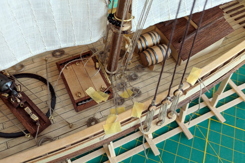
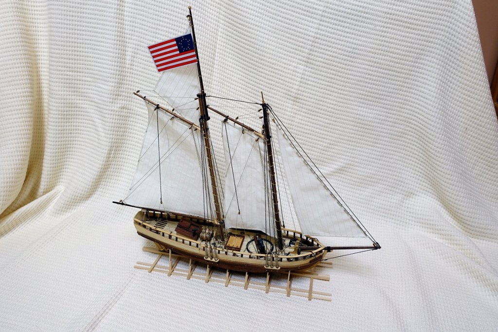
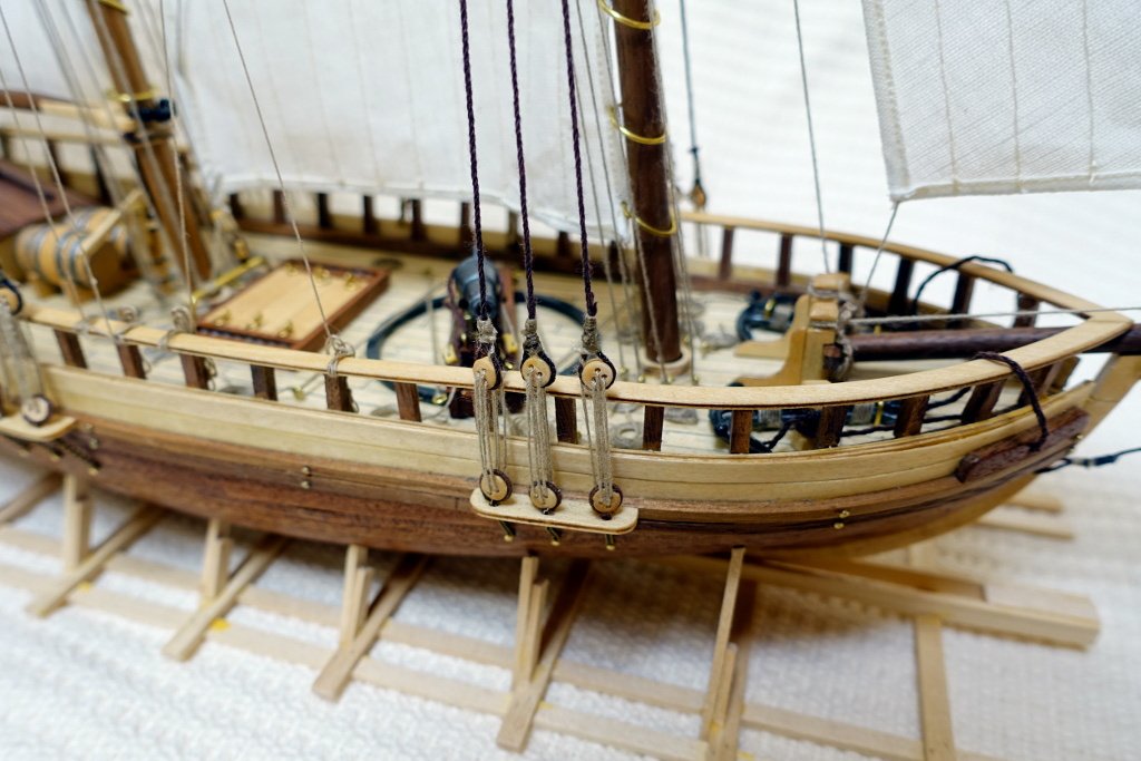
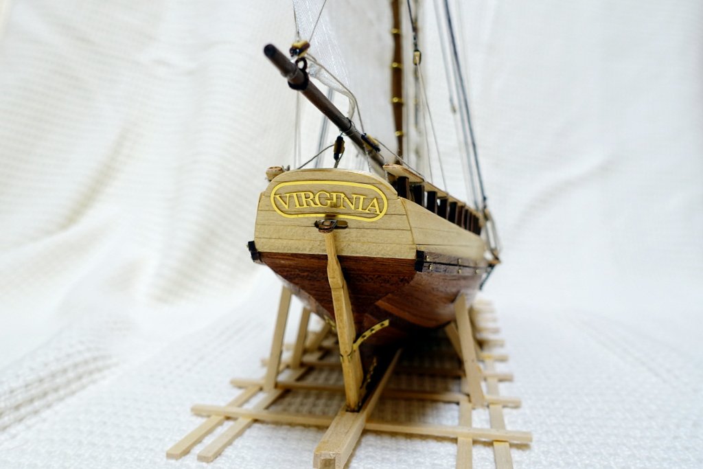
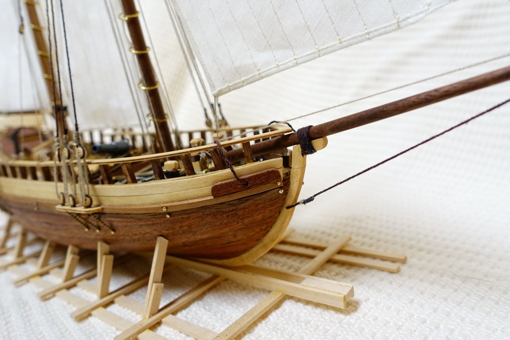
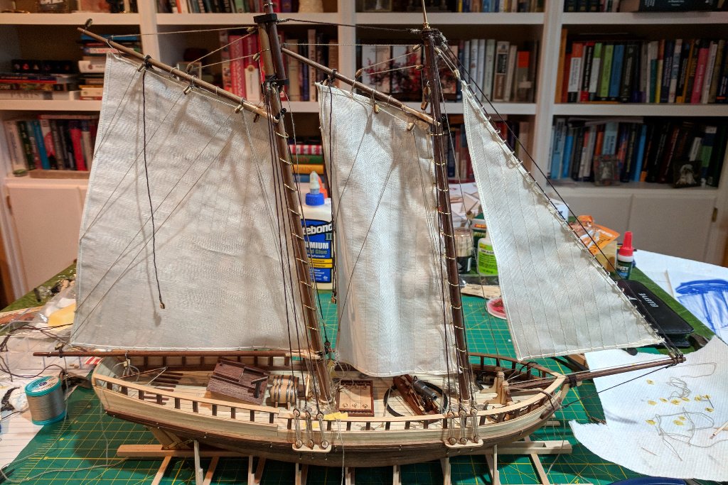
Rigging was adjusted and tape was used to apply tension to the lines. With the lines secured in this way, a drop of CA glue was used to hold each line in place, and the excess material was cut off. Rope bundles were added at various points where lines were secured. Put a flag on her and she's done. Some shots of the completed model.

- 54 replies
-
- 12
-
-
- artesania latina
- Virginia
- (and 2 more)
-
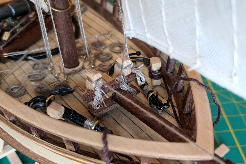
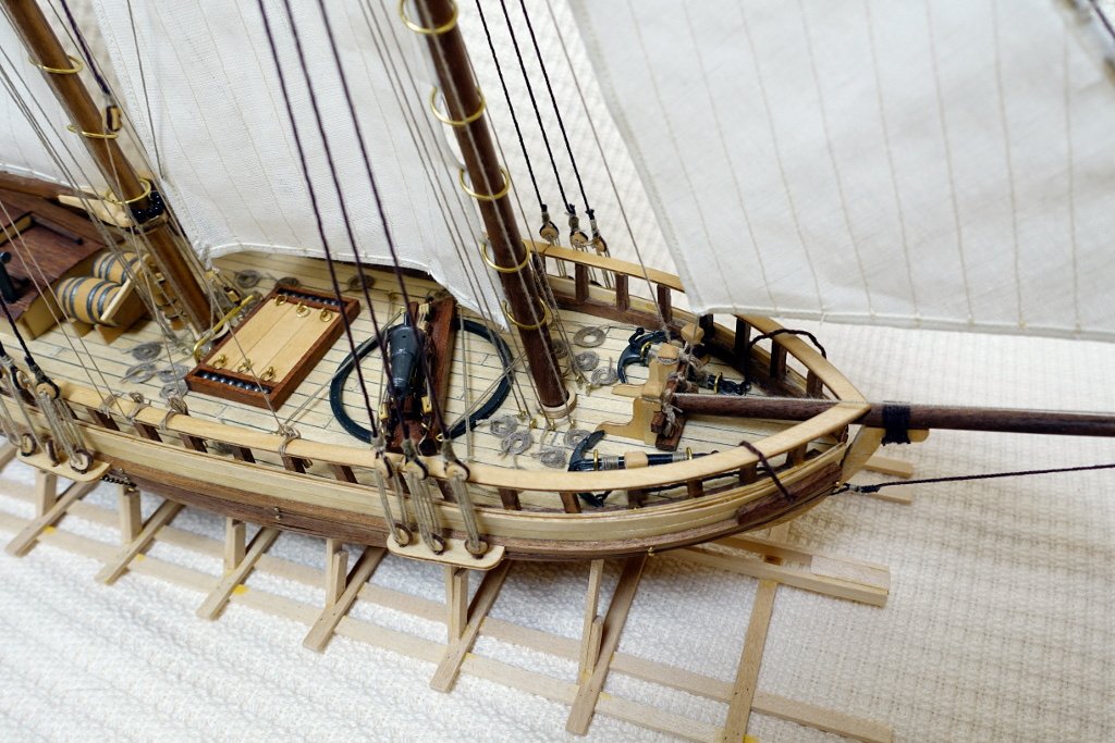
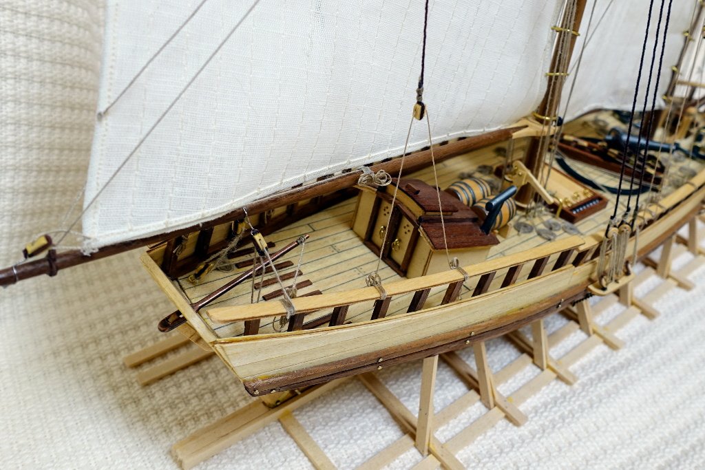
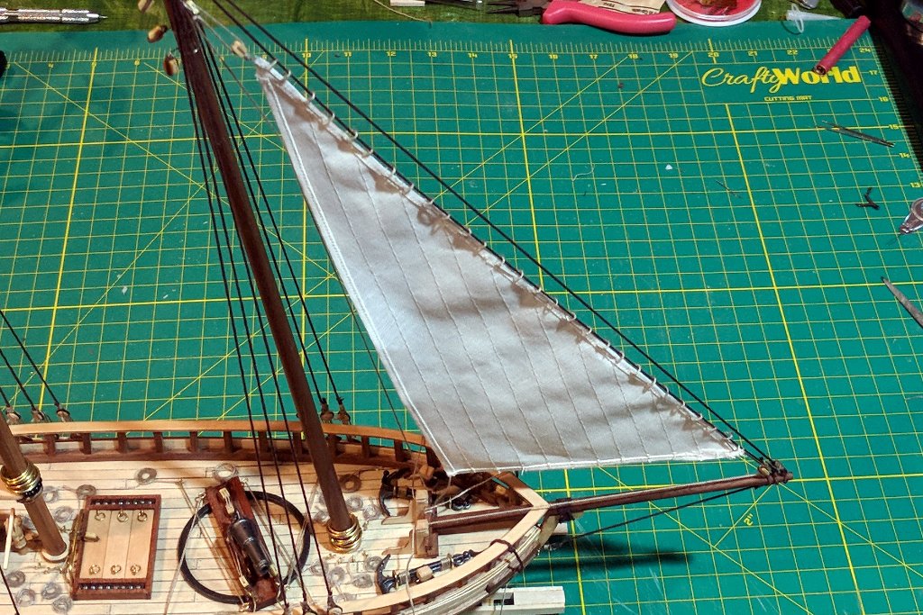
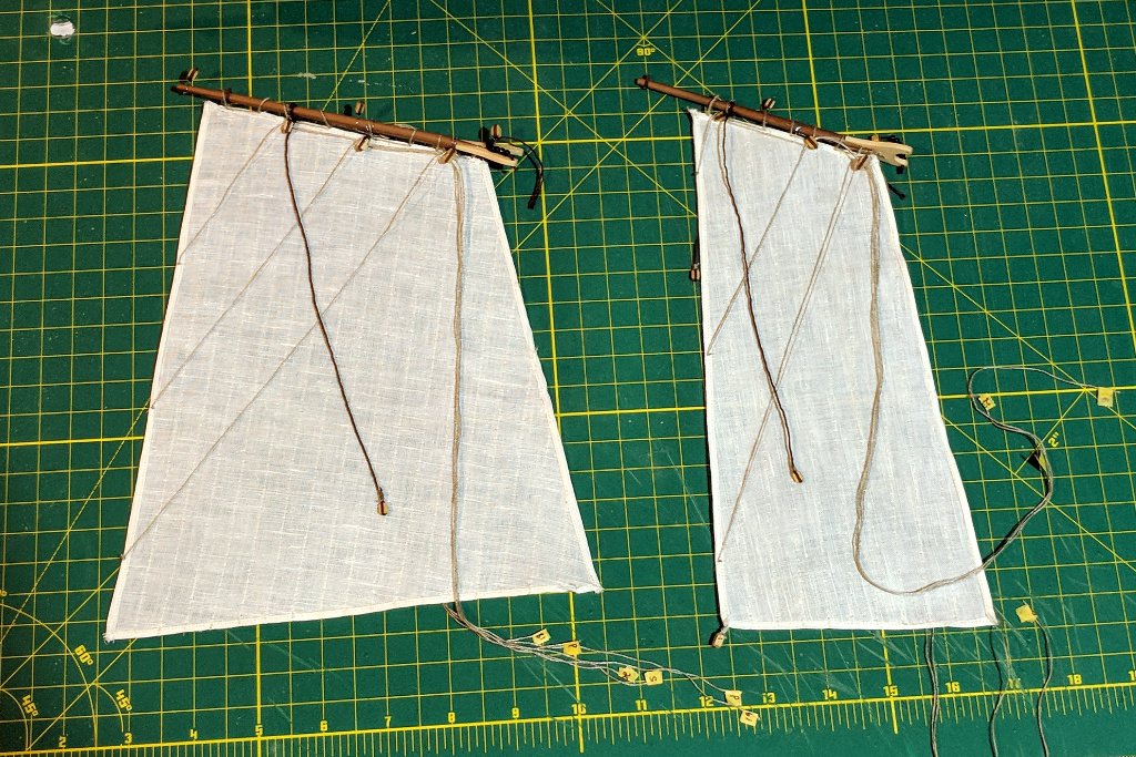
At last everything is coming together. The first sail I attached was the jib. In the picture, you can also see how I pre-laid a number of rope coils around the masts. I hope that I can secure the lines from above in such a way that they appear to connect to the rope coils. The foresail and mainsail were attached to their respective gaffs. I realized that the brails could be run before the sails were attached to the ship, so I added those at this point. And the foresail and mainsail are in place. There are a number of small issues, but the worst is that the foot of the foresail is long enough that it goes aft of the mainmast, but the bar that that foresail sheets attach to is forward of the mainmast. My replacement sail is the same size as the kit-supplied sail, so it is a flaw of the kit.
- 54 replies
-
- 5
-
-
- artesania latina
- Virginia
- (and 2 more)