DARIVS ARCHITECTVS
-
Posts
126 -
Joined
-
Last visited
3 Followers


-
 DARIVS ARCHITECTVS reacted to a post in a topic:
Prins Willem by amateur - Corel - 1:100
DARIVS ARCHITECTVS reacted to a post in a topic:
Prins Willem by amateur - Corel - 1:100
-
 What happened to Sal?
 -
Gregory reacted to a post in a topic:
Deck planking
-
DARIVS ARCHITECTVS reacted to a post in a topic:
Deck planking
-
cotrecerf reacted to a post in a topic:
Deck planking
-
dafi reacted to a post in a topic:
Deck planking
-
druxey reacted to a post in a topic:
Deck planking
-
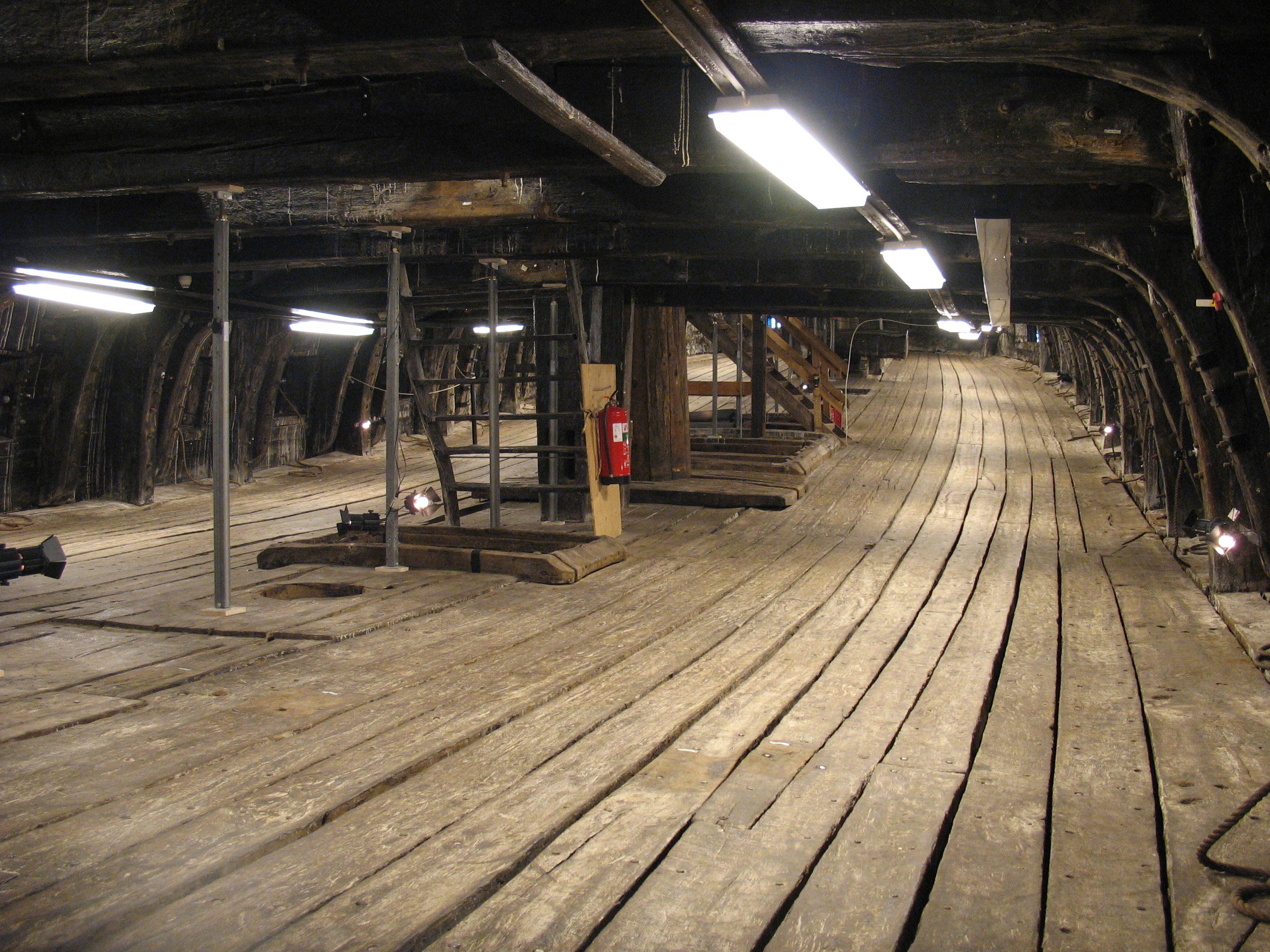
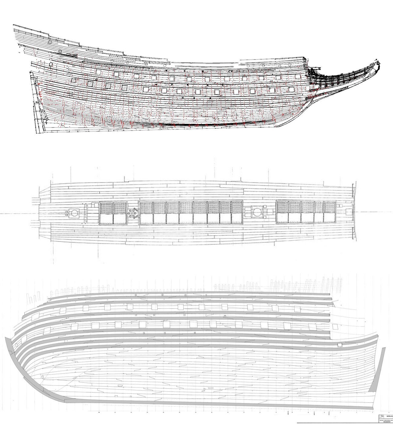
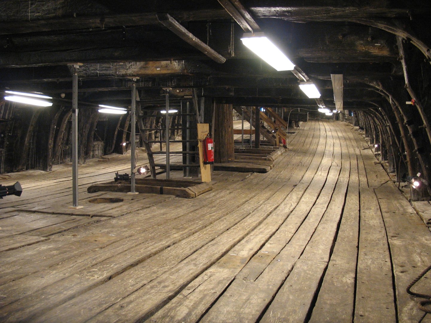
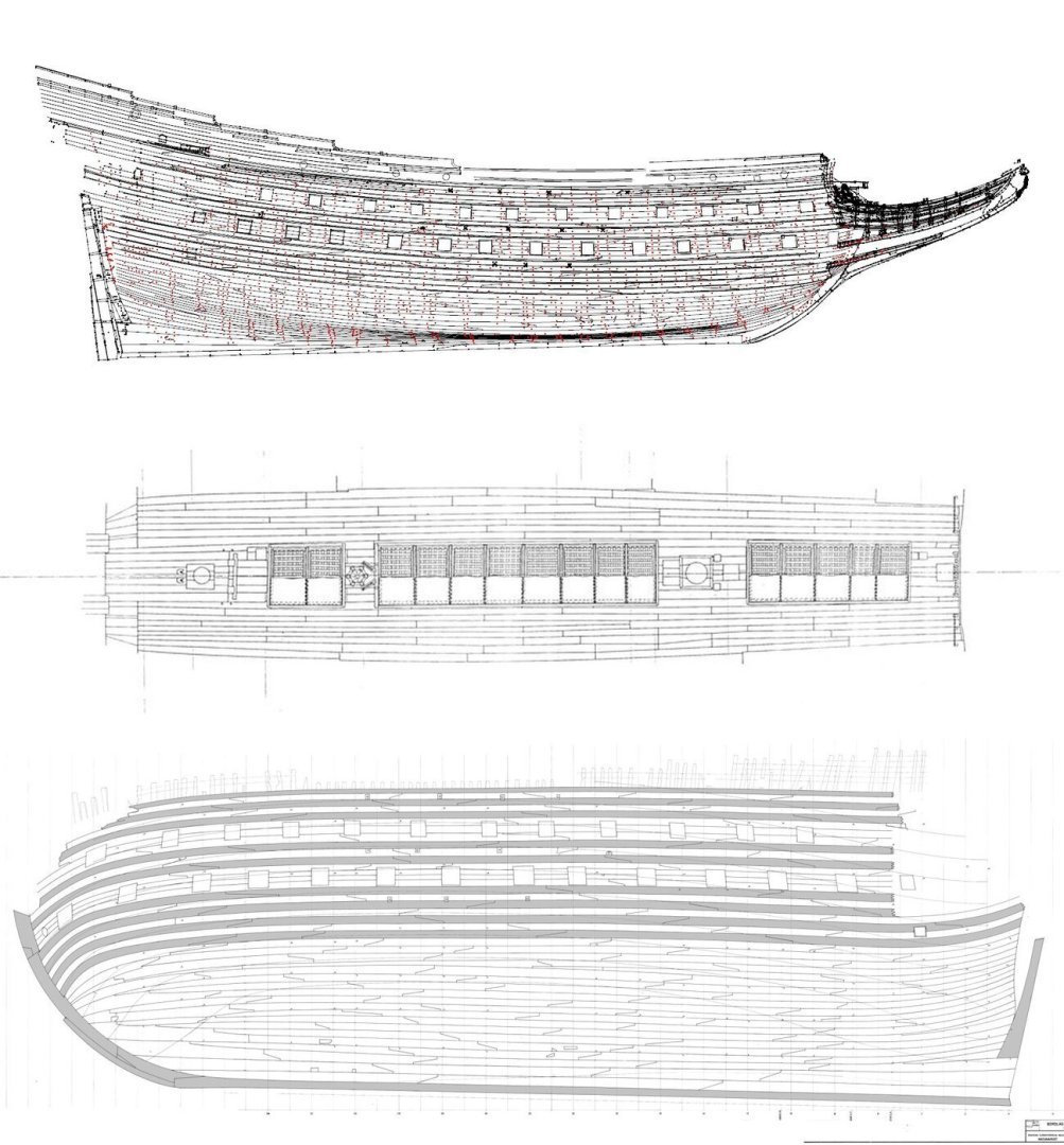
There is no correct way. If you were to look at the planking across 4 centuries, you ultimately come to the conclusion that planking for every ship is unique. Even sister ships have similarities, but the sizes of wood planks available dictates. There are some standard patterns, but these are never strictly followed. 17th Century ships often have little or no pattern, e.g. Vasa below. Even the width of planks could vary. If you stick with late 18th or 19th century vessels, you MAY find information as to the pattern used on your ship of interest, such as the pattern used. If you post the name of the ship you are building, someone on the forum may be able to provide some information on the planking pattern, if it even exists. Beyond that, you have to guess.
-
DARIVS ARCHITECTVS reacted to a post in a topic:
Prins Willem by amateur - Corel - 1:100
-
DARIVS ARCHITECTVS reacted to a post in a topic:
Prins Willem by amateur - Corel - 1:100
-
 DARIVS ARCHITECTVS reacted to a post in a topic:
Prins Willem by amateur - Corel - 1:100
DARIVS ARCHITECTVS reacted to a post in a topic:
Prins Willem by amateur - Corel - 1:100
-
 DARIVS ARCHITECTVS reacted to a post in a topic:
Prins Willem by amateur - Corel - 1:100
DARIVS ARCHITECTVS reacted to a post in a topic:
Prins Willem by amateur - Corel - 1:100
-
DARIVS ARCHITECTVS reacted to a post in a topic:
Prins Willem by amateur - Corel - 1:100
-
DARIVS ARCHITECTVS reacted to a post in a topic:
Prins Willem by amateur - Corel - 1:100
-
DARIVS ARCHITECTVS reacted to a post in a topic:
Prins Willem by amateur - Corel - 1:100
-
DARIVS ARCHITECTVS reacted to a post in a topic:
Prins Willem by amateur - Corel - 1:100
-
Erik A reacted to a post in a topic:
Which is the oldest book on shipmodelling?
-
Okay. I'll watch for when you get done with Gracie S. and check out that model's build log.
-
Any news on your La Couronne build ?
-
Me too. I'm a huge fan of early 17th century ships. They were ornamental and had complicated rigging, so they make for pretty models. When ships advanced in design, they became so utilitarian that from a distance, they all seem to look alike. It's difficult to make accurate and detailed models of 17th century ships because of the limited historical information, but we still like to make models of them.
-
Imagine what Chris could do with HMS Sovereign of the Seas...
-
I noted that the Italtian lime wood provided with Corel kits is more dense and has tighter grain that American bass wood here in the USA. The Corel strips were flexible and less likely to splinter. Perhaps this is owed to where the trees grew since soil type has such an effect on wood.
-
Welcome, Tuvoc! I've always been a great admirer of your work.
-
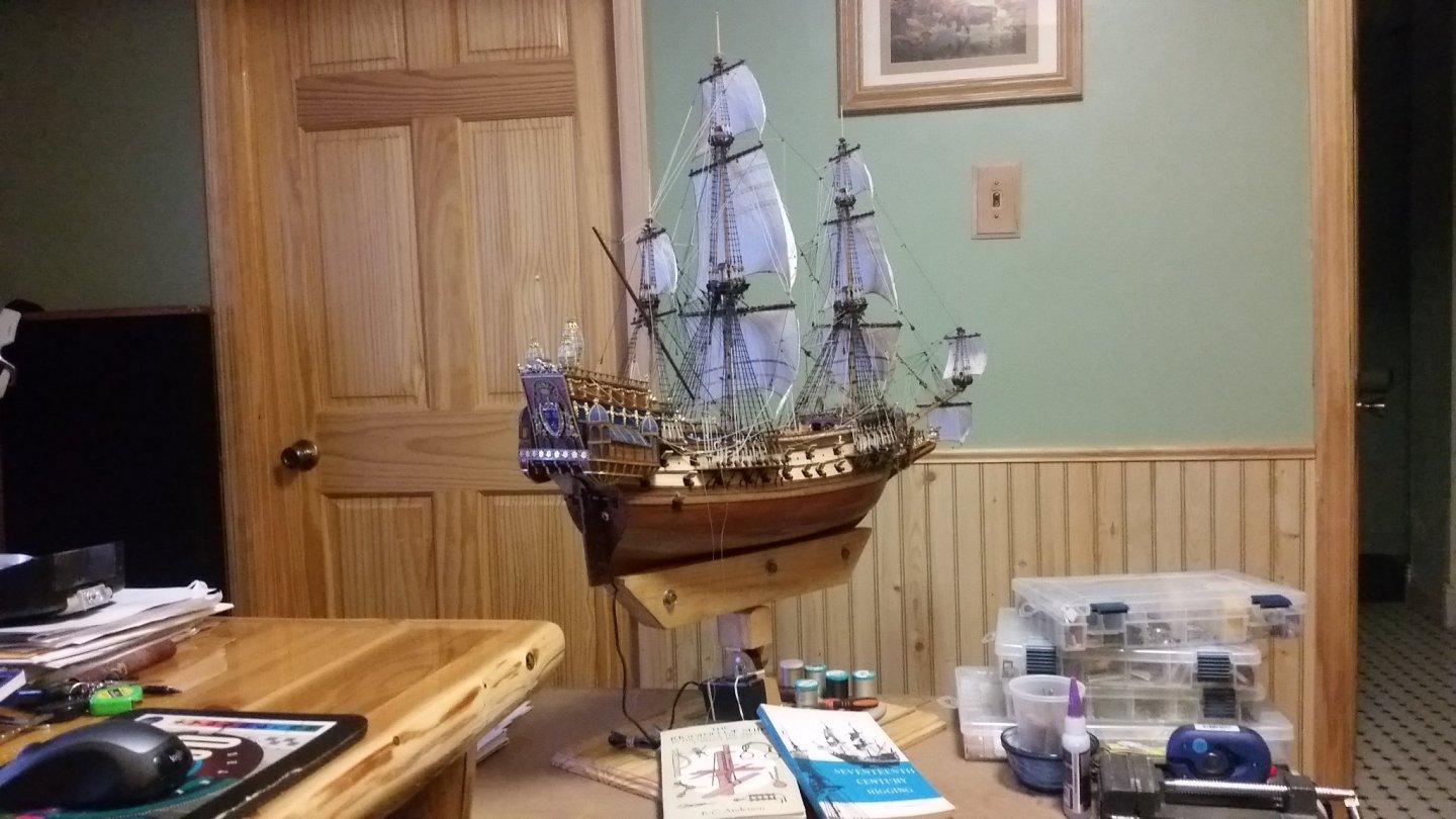
Wow, EJ! What a massively wonderful ship project! I hope you have someplace with room to display it when it's done. Best wishes! Kurt
-
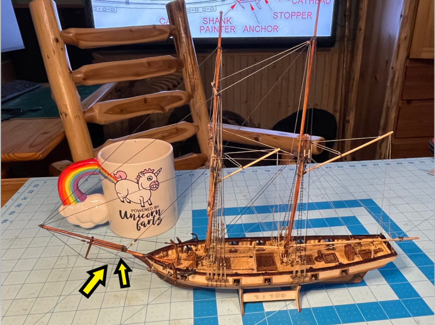
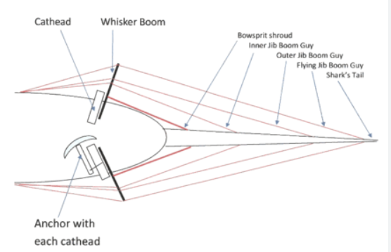
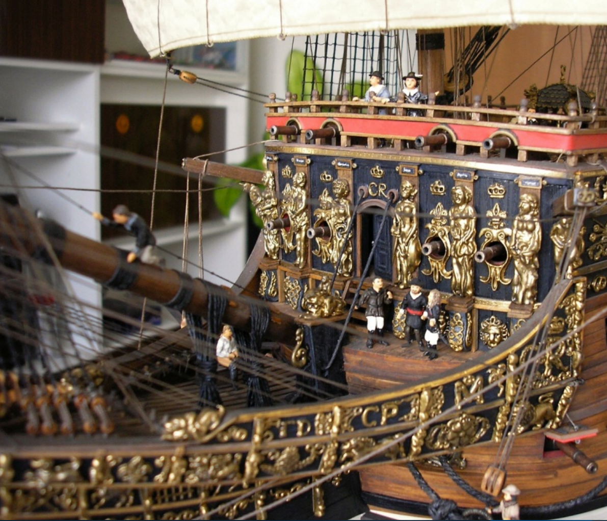
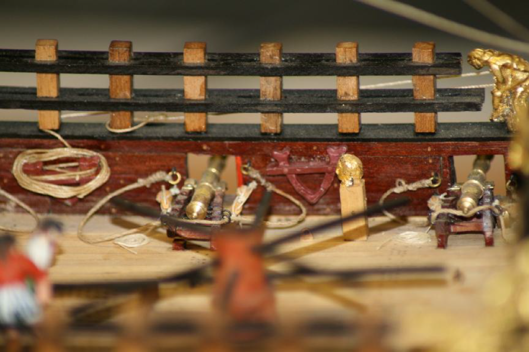
I'm confused why Don states that bowsprit shrouds and bobstays were not used on SotS. Bowsprit shrouds are not to be confused with the shrouds for the bowsprit topmast. Bowsprit shrouds on modern yachts run from the bowsprit to the hull on either side of the vessel, and prevent the bowsprit from bending to port or starboard. Typically the aft end of the shroud is attached to the hull using a thimble and shackle to an eye bolt which goes through a chain plate that is bolted to the hull. Take a look at my model of the Halcon of 1840. There are two bowsprit supports on each side of the bowsprit. One "guy" line starts at the tip of the bowsprit and runs to the dolphin striker where it splits into two guys which have tackles attached in turn to the hull (large arrow). The other is a bowsprit shroud that runs from a collar at the base of the dolphin striker and runs to a tackle on either side of the hull, near the guy tackle (small arrow). So, yes, SotS did not have bowsprit stays. As to where the bowsprit running rigging was belayed, that is unknown. Doris Obručová's model has a belaying pin rack located on either side of the beakhead (below). Perhaps there were cleats on the deck or railings or kevels on the inboard sides of the beak. We don't know. Vasa had a pinrail on the beakhead deck. Don Dressel rove running rigging lines through blocks fastened to the gammoning, and then up to the forward railing on the forecastle on his model, or directly from the blocks attached to the bowsprit, located foward of the spritsail yard but behind the bowsprit top, rearward to the forecastle railing.
- 327 replies
-
- 6
-
-
- Sovereign of the Seas
- Airfix
- (and 1 more)
-
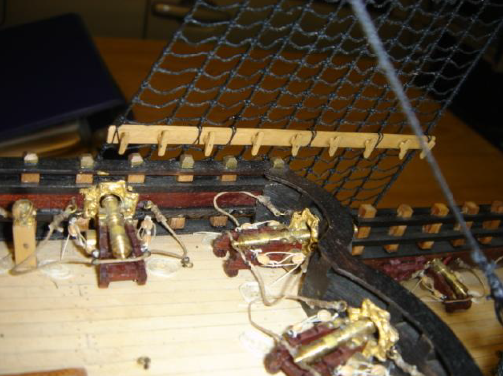
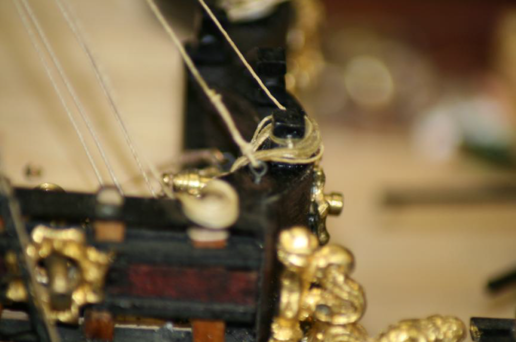
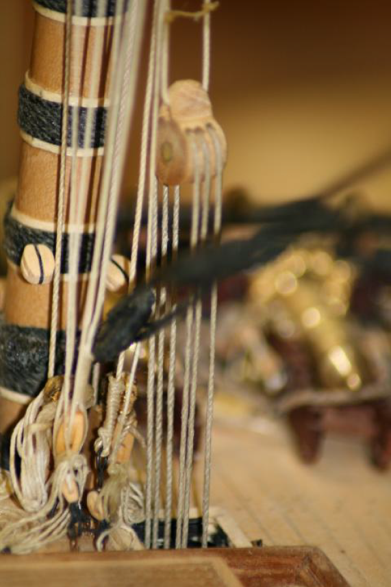
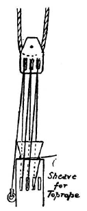
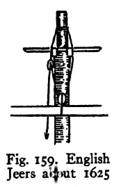
SotS had old style rigging. Don Dressel stated that SotS had both jeers AND ties and halliards, which is unusual. It is not stated whether jeers and ties/halliards were both used on the same yardarm, which seems redundant to me, but a single yard would have jeers OR ties/halliards. James Sephton also believes both jeers and ties/halliards were probably used on SotS. The fact that other aspects of the rigging were old lends weight to the conclusion that ties and halliards were used for at least some yard rigging of the yards on SotS, instead of heers for all yards. Perhaps jeers were only used on the lighter yards. I do not know, but this seems logical. Payne's engraving shows ties and lanniards being used for the fore and main course sails. Sometimes a ship's features can only be determined by context clues. Some older style rigging arrangements used on SotS are shown below. Which lines were belayed to where is lost to history fort this ship, however there are clues in Payne's engraving, which shows the typical rigging for a large ship at the time, but does not depict the actual rigging used on SotS because it was engraved before the actual ship was rigged. It's all the info we have. Some belaying points may be deduced from the engraving. Payne's engraving has several shortcomings, including the fact that it does not show parrels for the heaviest yards and lateen yard on the mizzenmast. We have to take our clues were we find them and let them guide our guesses. Shroud cleats Hitched to railings at the timberheads Fore course yard tie is looped from yard to block to yard, with halliard rove through the block This sketch from Robert C. Anderson suggests that jeers using single sheave blocks would have been used on lighter yards higher up than the course yards, and evidenced by his drawing of the crosstrees. So, perhaps ties and halliards were reserved for the heaviest yards, pehaps including the topsail yards. SotS may not have employed belaying pins, but lines were belayed to deck rings, railings, and kevels. Rigging_Techniques HMS SotS.pdf
- 327 replies
-
- 4
-
-
- Sovereign of the Seas
- Airfix
- (and 1 more)
-
I like to leave the model in the home made keel vice, because mine tilts to the side 45 degrees, making rigging some lines much easier than when in vertical position. Ratlining is easier too, especially for the topgallant masts.
-
Whats the best book on rigging for a beginner?
DARIVS ARCHITECTVS replied to Stuka's topic in Masting, rigging and sails
Forum build logs are a good source and the least expensive (free) for details such as knots, splices, worming, and other techniques. When ask a general question about rigging, it is hard to answer without more specifics. First, what time period are you asking about, and what nationality is the vessel? This narrows things down a bit. Some books focus on rigging styles from certain eras, most commonly the 18th century. Using a source out of time period or nationality will steer you in he wrong direction. English and European continental styles of rigging are the two largest classifications for rigging style by region. For the 17th century, The Rigging of Ships: in the Days of the Spritsail Topmast, 1600-1720 by R.C. Anderson covers multiple nationalities. For the 18th century, The Art of Rigging by George Biddlecombe has lots of detail on knots, splices, seizes, and other methods of tying, hitching, and binding. As previously mentioned, The Rigging of Period Ship Models : A Step-By-Step Guide to the Intricacies of Square-Rig and Rigging Period-Fore-and-Aft Craft by Lennarth Petersson offer a pictorial way of showing you how lines are routed on specific 18th century vessels which provide example of how lines are routed and belayed. You want to shop for books that cover your vessel of interest as close as possible in order to rig your model as historically accurate as possible, using educated guesses where required instead of wild guesses. The shotgun approach of buying books is wastefully expensive. If you need to know what a particular book contains as far as information, it costs nothing to ask other forum members who own such books what is in them. When buying books, shop around. The kindle electronic versions are very inexpensive if you don't mind reading off your computer or cell phone, but the photographs suffer detail and quality significantly. Books specific to certain classes of vessels like the ones available from SeaWatch are very expensive, but if your model falls within their scope and you want the most and best information on a vessel, they are worth the money. I hope you find that there are few pieces of useful information in my ramblings. -
I don't know. Found them in the bowels of the internet.