HOLIDAY DONATION DRIVE - SUPPORT MSW - DO YOUR PART TO KEEP THIS GREAT FORUM GOING! (Only 13 donations so far - C'mon guys!)
×


Rcboater Bill
-
Posts
167 -
Joined
-
Last visited
Content Type
Profiles
Forums
Gallery
Events
Everything posted by Rcboater Bill
-
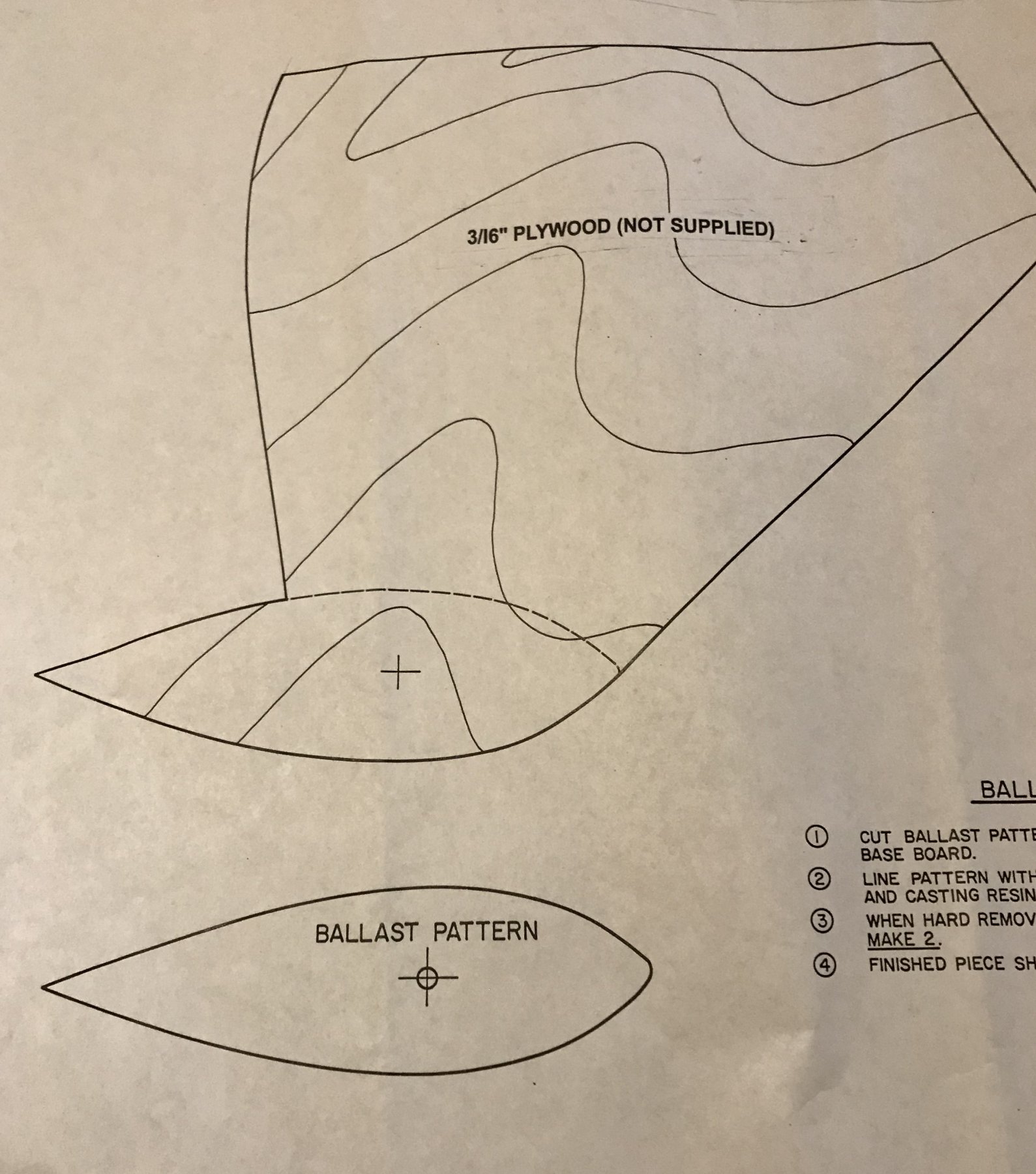
 The kit includes a drawing for a keel and a recommended shape to use to make your own lead bulb. No installation instructions are provided, but it is pretty obvious that the fin is shaped to fit in the centerboard slot. The assumption is that you’d just glue it in, it seems. A club mate built this model as an RC Boat. He made the keel removeable, with a threaded rod embedded in the fin, and a wing nut to retain it in the hull. (The usual method used on most ARF sailboats.) He glued the kit centerboard to a nice display base. When he gets home with the model, he removes the sailing keel and sets the model on the waiting centerboard. I think that’s pretty clever, and I am planning to copy it. I took a photo of the relevant section of the plan, showing the shape of the keel. -Bill
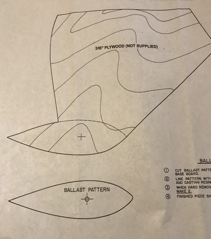
- 41 replies
-
- 1
-

-
- muscongus bay lobster smack
- BlueJacket Shipcrafters
- (and 1 more)
-
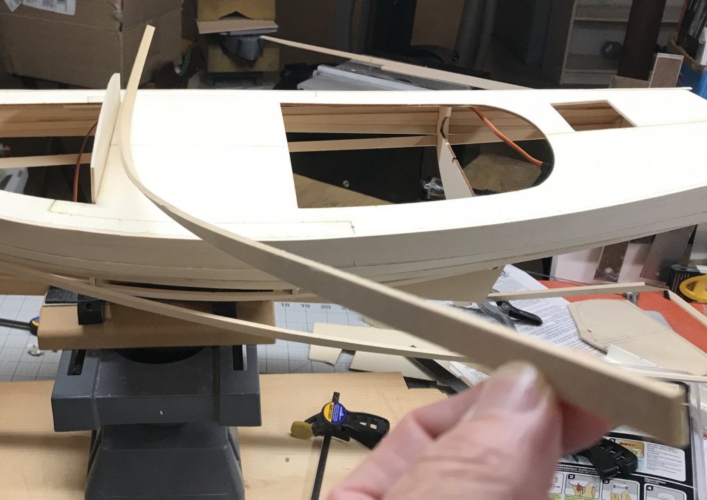
This is an example of a 3 foot long basswood plank after soaking, clamping in place, and letting it dry. Makes installation so easy!
- 41 replies
-
- 5
-
-
- muscongus bay lobster smack
- BlueJacket Shipcrafters
- (and 1 more)
-
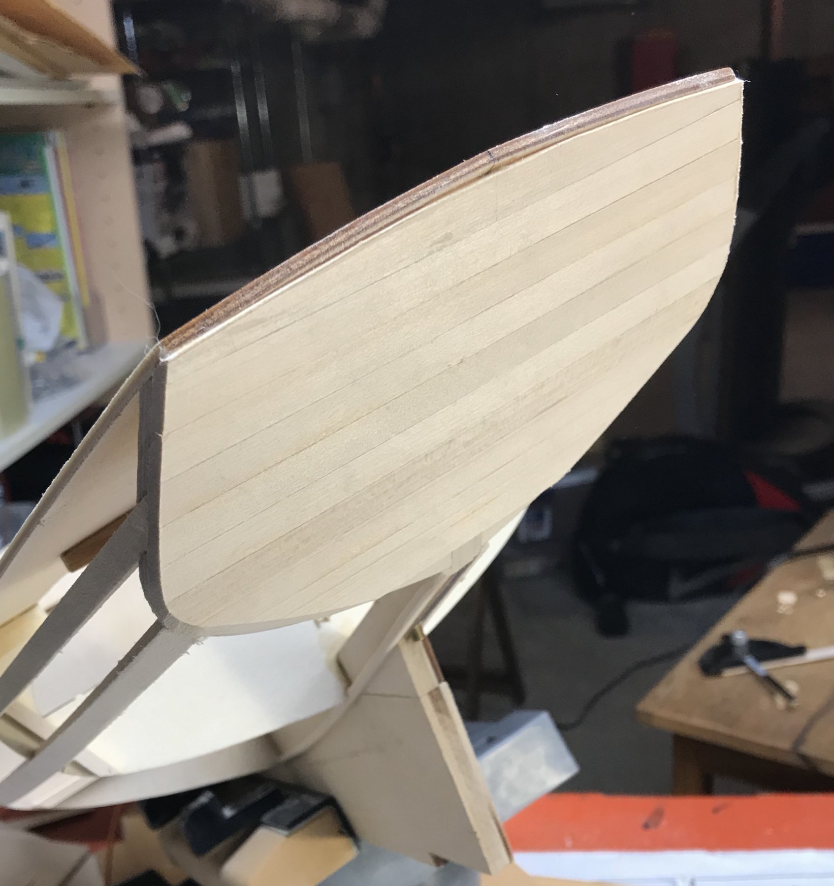
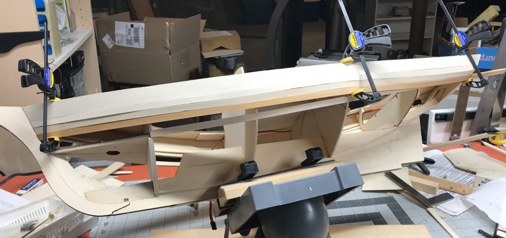
I am still slowly working on the model. It is rather chilly in my basement shop, so I am not spending a lot of time down there these days.... But I have made a start on the planking. I’ve got the first two added to hull P&S. My procedure is to put a 1/8 by 3/8 basswood plank in the PVC pipe to soak over night. The next day, I’ll pull it out, and clamp it in place to dry. A day to three later, I glue it in place and put the next one in the soaker... It is a slow process, drawn out much longer than it needs to be, but it allows me to at least make some progress while it is so cold down there...! Here you can see the wet third plank on the port side clamped in place to dry. Once it dries, I find the pre- formed plank is much easier to glue in place. Note that the apparent mismatch between a couple of planks is a bit of an optical illusion- the hard shadow is caused by the location of the overhead light. There is a slight step in places, but that will quickly disappear when sanded. -Bill
- 41 replies
-
- 3
-
-
- muscongus bay lobster smack
- BlueJacket Shipcrafters
- (and 1 more)
-
Yes, I missed the name. (In my defense, it comes up as tiny grey text on a black highlight on my tablet.) In light of this, I have edited my previous comments in post #107, so they make more sense..
- 446 replies
-
- 3
-
-
- zebulon b vance
- deans marine
- (and 3 more)
-
Kevin, That is an interesting photo - thanks for sharing it. You can see that a prop is going to be there for a voyage- you can see the anchor points on the deck for each end of the tie downs that go over the prop blades. This is what I love about forums like this- you can learn something new from people all over the world. I couldn't find any info about what type of ship the Wei Lee is, so I’m not sure how relevant it is to my earlier question. But I did say I had never seen a prop stored like that, and now I have! (I still think it is a weird thing to put on a hospital ship!). 😎 -Bill
- 446 replies
-
- 4
-
-
- zebulon b vance
- deans marine
- (and 3 more)
-
Steve That is very unusual- I have never seen a spare prop carried on the foc’sle like that - on any ship, any size. (Real or model.). I am really surprised the Dean’s kit tells you to do that. As a former sea-going officer, it just doesn’t make sense to me - it is not like a spare tire on a car. Props for a ship that big are huge, heavy, and expensive. A ship needs to be in dry dock to swap it out- it is not something the crew could do while at anchor. If a spare prop was on board, it would likely be crated, and stored in the hold- no sense in having all that extra weight topside. If it was carried topside, it would have to be very thoroughly tied down, so it can’t move. I’m curious, does the kit kit include a photo or other evidence this was ever really done on the Vance or her sisters? As I said, it seems odd to me, but it also seems unlikely that Deans just made it up. It is possible, I suppose, that an empty hospital ship on its way to the war zone could be used for an urgent delivery to a forward base. But that would be a very unusual... Do any of the photos in your Hospital Ships book show this? You’ve got me really curious...... -Bill PS- I am loving your build- you are doing a fabulous job, and I think it is looking great, and will really be something on the water. You even have me looking at photos onlin, thinking “Maybe I should build a hospital ship out of my extra freighter hull.”
- 446 replies
-
- 2
-
-
- zebulon b vance
- deans marine
- (and 3 more)
-
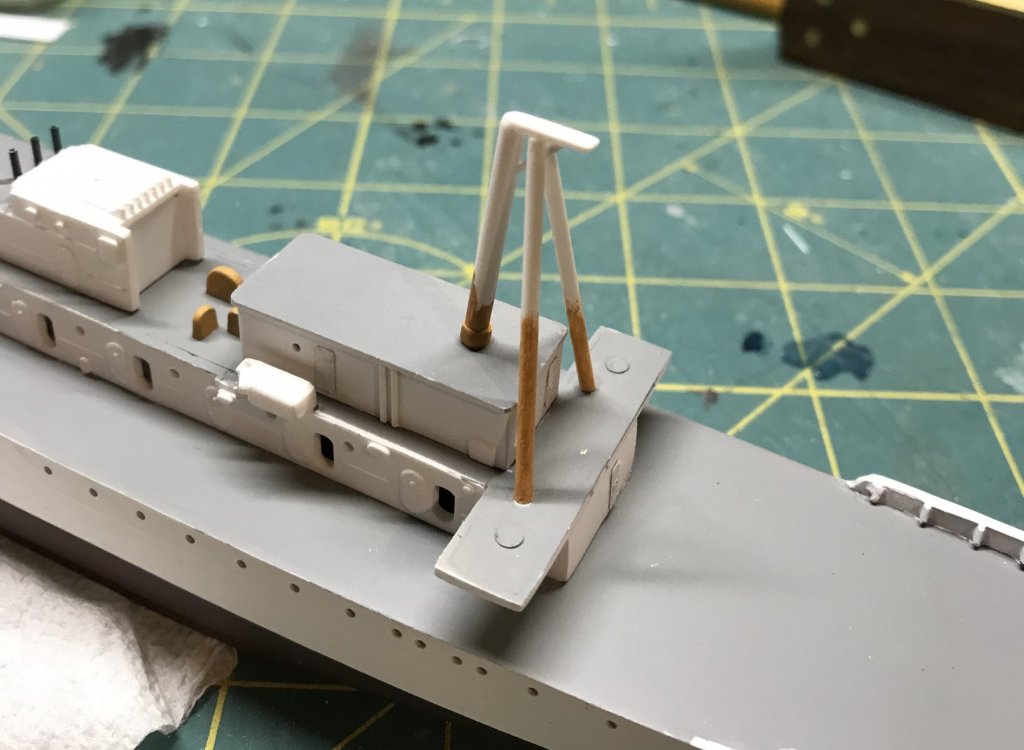
Robert, I’m really enjoying your build- it is looking great, and will surely be a impressive on the water! I am a little surprised by the size of the triangular braces on the bulkheads/ spray shields around the bridge. I’ve been on a number of ships, and have never seen braces that big! Standing a watch at sea there would be a challenge- those things are tripping hazards! Makes we wonder if Deans had a drafting error...? -Bill
- 446 replies
-
- 2
-
-
- zebulon b vance
- deans marine
- (and 3 more)
-
I have (finally) successfully installed both of the 1/8” x 1” sheer planks, and can now move on to the smaller planks. I have to say- I don’t get why Laughing Whale designed the kit this way. The first step in planking the this hull is the hardest- trying to bend a one-inch wide plank to match the boat’s sheer. It was really hard to do, and if you mess it up, it will affect the rest of your planking job. In hindsight, I should have tossed those 1” wide planks and used narrower stock. Could have saved myself weeks of time- making jigs, soaking, test fitting, ironing, waiting for stuff to dry, re-soaking, etc. etc. Nic- When the time comes for you guys to look at updating this kit, I’d suggest taking a hard look at this step....!
- 41 replies
-
- 1
-
-
- muscongus bay lobster smack
- BlueJacket Shipcrafters
- (and 1 more)
-
The BJ kit provides a lovely thin piece of laser cut mahogany to be attached to the ply transom. But I am not going to use it, for two reasons: One, I think that while a nice varnished mahogany transom would be gorgeous, I think it is too “ yacht-y” for a hard working fishing boat. Two, even if I wanted to use it, it is too small, because I had earlier replaced the kit ply transom with a new one that is slightly wider, to better match the deck. I was looking in a book I have on Frienship sloops, and it had a nice photo that showed the construction of the transom, which was planked. So I decided to just plank the transom with some of the 1/8 x 3/8” stock. A benefit of this is that I have effectively doubled the gluing area for the planks where they overlap the transom.

- 41 replies
-
- 4
-
-
- muscongus bay lobster smack
- BlueJacket Shipcrafters
- (and 1 more)
-
Steve, I may be too late now, but if I was doing that, I would have used strips of clear plastic to do a whole row of portholes, instead of cutting out individual pieces. The other thing you might want to consider is to randomly "close" some of them. Think of the windows at a hospital -- not every patient room has their blinds open at the same time of day. Most portholes have an inner hinged cover that can be locked in place over the glass-- a damage control feature. To close them, I would just put a piece of what plastic over the clear from the inside. From the outside, that will look like the glass, with a closed cover behind it. One other thng to you might want to consider-- adding a light block to some of the cabins. In most places, you should not be able to see through the model. Putting a thin piece of (dark) plastic down the centerline on the inside of the superstructure will block that. Finally, to your question about the bulwark braces-- it is very possible that they are not uniformly spaced on the real ship. There will be deck fittings coming later, such as the chocks and bollards for securing mooring lines. That might account for some of the unusual spacing.... Hope this isn't too late to be of help.... -Bill
- 446 replies
-
- 1
-
-
- zebulon b vance
- deans marine
- (and 3 more)
-
I spent an hour playing around with the RC tiller and aileron bellcranks and a servo to figure out the right geometry to use. Sorting something out is complicated by the open cockpit and the fact that the rudder axis is about 30 degrees from vertical. This makes the geometry of the linkage rather tricky, as a tiller not only moves port - stbd, but has a vertical change as well. My conclusion: I am going to mount the rudder servo aft. I will cut an access hatch aft, and then install the servo at the same 30 degree tilt as the rudder, to put the servo arm and the tiller in the same plane. This will give me a simple direct linkage for the servo to tiller connection. My plan is to use a high-torque metal geared servo, as I expect a standard servo may not be able to handle the loads imposed by the large, unbalanced rudder.
- 41 replies
-
- 1
-
-
- muscongus bay lobster smack
- BlueJacket Shipcrafters
- (and 1 more)
-
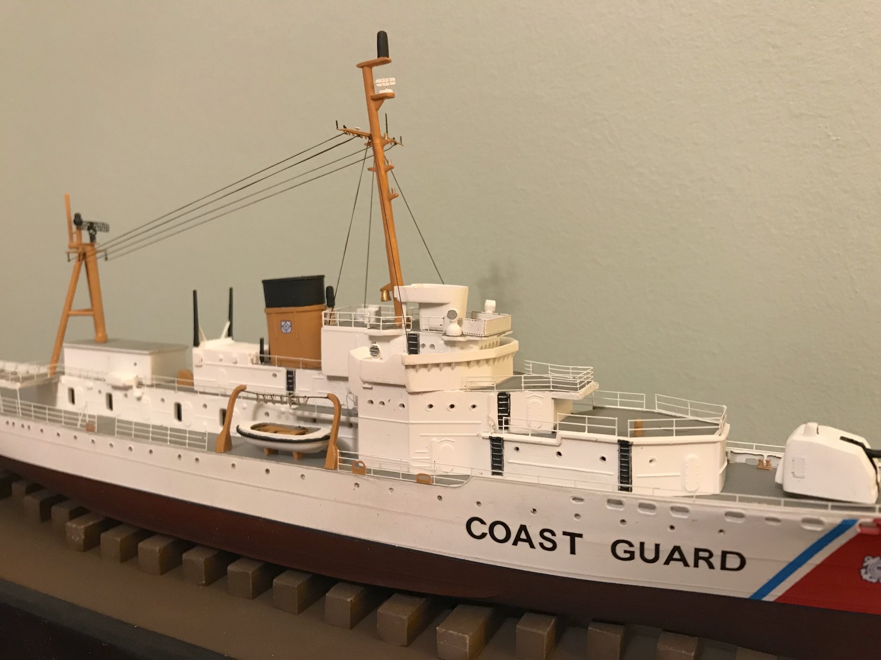
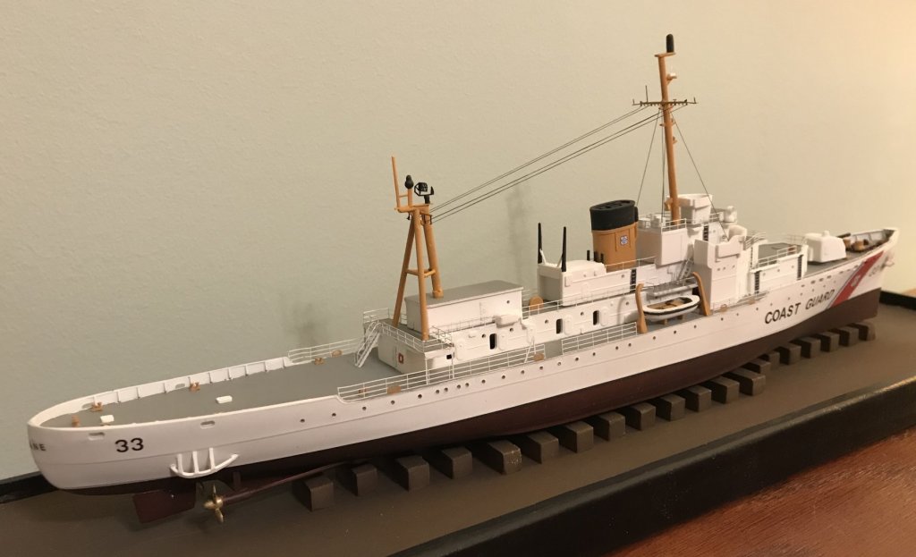
I took a couple of months off from this build, so I could finish my Revell USCG Cutter- a gift for a classmate and former crew member. (Completed build log is here on MSW.) I delivered the model last weekend, so now it is “Back to the Smack”! In the long time off, the sheer plank I had soaked and bent lost about half the curve. So I soaked it again and put it back in the jig. As I fiddle about with the planking preparation, I am also thinking about installing the RC. The kit gives a simple diagram for a suggested RC install, but working out the details is up to the builder. I realized that working out the layout and geometry will be a lot easier now, before the planks are installed. I did some test fitting, and quickly determined that a sail arm servo isn’t going to work, so I bought a drum sailwinch. There are other considerations I need to sort out in regards to making this an RC model. One is the rudder linkage- the suggested install has the rudder servo in the cabin, and a Gold’n’rod aircraft style “flexible” pushrod linkage to the rudder. I bought one at the LHS, and it seems like an awfully tight radius at the stern for the pushrod to make. The next more flexible rod uses a small diameter cable center, and I’m concerned that it wouldn’t be strong enough to handle the loads imposed by the boat’s huge unbalanced barn door rudder. So maybe I need a bell crank aft...? I’m also concerned about watertight integrity. As designed, the entire aft end of the boat is open to the bilges. (The fish well and the fore peak are sealed compartments.) That would be OK for a calm water motorboat, but seems like asking for trouble with a sailboat....
- 41 replies
-
- 1
-
-
- muscongus bay lobster smack
- BlueJacket Shipcrafters
- (and 1 more)
-
Doesn’t appear to be free- online version subscription is $10/ month, or you can buy the desktop version for $295.... Don’t think I would use it enough to justify buying it, but might be worth signing up for a month or two when starting a new project... Thanks for sharing the link! -Bill
-
I just stumbled across this thread- looks like offer is still in effect, but for the 2018-2019 version now. I’m curious - what are people using it for in ship modeling?
-
I ran into similar issues as Moxis did- scans of paper plans are full of stray pixels to clean up. I was trying to create a vector based image that I could send to the laser cutter... I use Inkscape as my drawing program, because it is open source (free) and can create and export .dxf files that the laser cutter wants. It also has a "bitmap to vector" conversion utility-- but that really struggles. Most paper plans we start with are not that good, quality wise-- and when you scan them, you get all sorts of stray or missing bits. I found I had to go into each image file and use an editor like MS Paint to erase stray dots, and to fill in the little white gaps, to try to create a continuous black line. Was way more time consuming than doing it the old school way! So now to the reason for my post-- it occurred to me that maybe a blend of the two methods would be more efficient. If only there was a way to take the easy-to-make paper templates and then trace around them using the free hand draw tool in the program...... So I looked online, and I see that there are a lot of (fairly inexpensive) drawing tablets, that come with a stylus - I'm thinking one of these would be perfect for tracing around a paper pattern. They are primarily marketed to artists, for drawing and creating sketches and other artwork-- can't find any reviews that talk about the use case I'm envisioning. But they seem to give you a lot more control than you'd get trying to draw with a mouse.... Anyone using one of these in a model building application??
-
I wouldn’t say they “ dropped the ball” with this kit. At the time, it was a big step forward by Revell, to make an accurate hull instead of something more suitable for a toy. The kit is state of the art for 1957. Removing the molded-on solid railings from any of those old kits is big improvement. A lot of the other work I did was a result of my desire to build a ship as it appeared in the 70s, as opposed to 1954....
-
When I did the brass on my Revell Coast Guard Cutter (build is on MSW), I followed the tips I found online on several sites when I googled the topic. The consensus was to soak the brass in full strength vinegar for 10-20 minutes. This will remove any finger oils, etc, and microscopically etch the brass. After the soak, rinse with water and dry the parts. ( I let them sit in a paper towel sandwich.) Then prime them using a good quality spray can metal primer. I use Tamiya fine white primer on small scale work like this. In your case, I would assemble sections, then do the vinegar soak and prime. -Bill
- 446 replies
-
- 2
-
-
- zebulon b vance
- deans marine
- (and 3 more)
-
I’m a latecomer to this thread- just found it! A couple of (too late?) comments: “Music wire” does not come on a roll. It is a hard steel wire, often sold in 3 foot lengths, and comes in a variety of diameters. It is used in the Flying models hobby for pushrods, landing gear, etc. Hobby shops that cater to RC aircraft will have it. Having said that, I seldom use it on an RC boat, except maybe for pushrods. I would vote against leaving the brass unpainted. You’re not building a mahogany yacht here! Plus it won’t stay shiny for long- it will weather unevenly over time. I would make a jig that has two purposes- to hold the stanchions while assembling and painting a section of rail, and as a jig to drill the holes in the deck. If you use the same jig for both jobs, the holes will have to line up. To paint the brass , I would clean it, then prime it with a good metal primer, then color coat it. ( Might be worth googling how the model RR guys paint their brass locomotives.) -Bill
- 446 replies
-
- 2
-
-
- zebulon b vance
- deans marine
- (and 3 more)
-
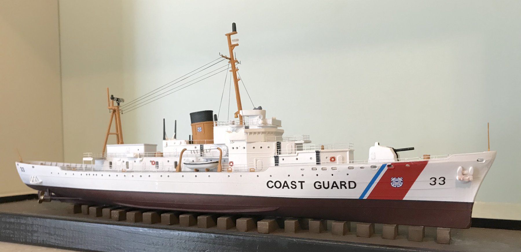
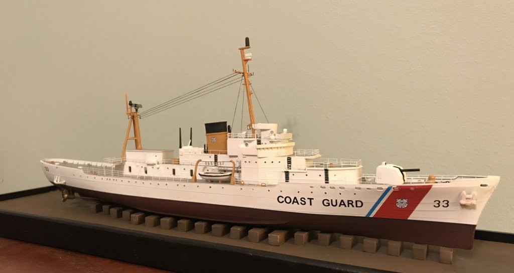
Almost done- Just need to add the jackstaff forward and the flagstaff aft, and she’ll be finished. A few notes about the masts: The mainmast was made by cutting up the kit part, converting it to a tripod was done using some styrene rod pieces of various diameters. The foremast is the kit part. Both masts have the yardarms from the GMM Detail set. The rigging is EZ line- I wanted something that would be durable, and the elasticity should provide that. In hindsight, I think I should have done the antenna wires in a smaller diameter line- but too late for that now! I do plan on making a cover over the holiday break....

- 35 replies
-
- 14
-
-
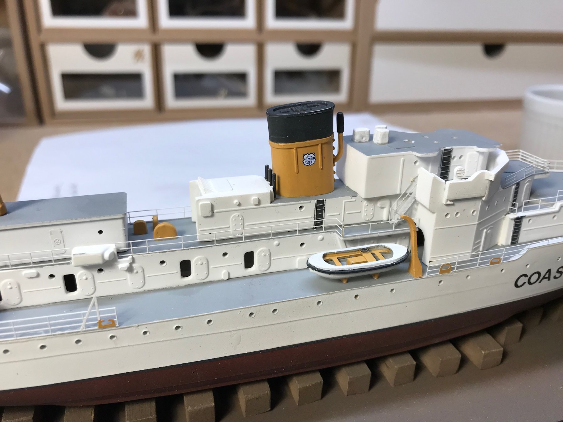
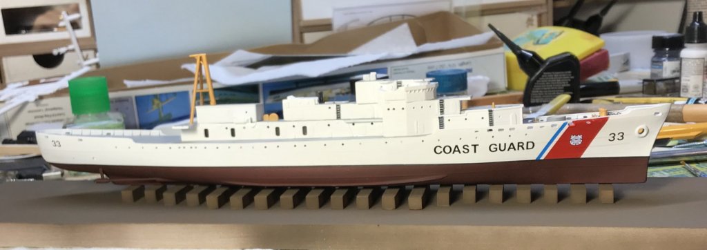
I have been slowly working on the railings. The GMM set is intended to go on an unmodified Kit, so there are way too few railings for my model. Fortunately, I had a stash of various 1/350 scale railings, and some of them are really close in size to the GMM ones. I generally don’t like using PE parts, but there was no avoiding them for this build. This is only my fourth model with PE railings, and it is going a bit better this time. Instead of using superglue, which can be very unforgiving, I am using white glue. I am using Aileen’s “ Tacky Glue”, which is thicker than Elmer’s and grabs quickly. I dilute it with water a little and apply it using a fine paintbrush. I find it also suits my schedule- I put one or two pieces in place, then walk away to let it dry. With the midships section upper decks done, I am starting on installing the boats and davits. You can see one of my reworked kit whaleboats- I am pleased with how they came out.

-
I took a few days to focus on finishing up the base. I added 3/4” high trim around the 1/2” base to cover the edges of the plank, mitered at the corners. I then painted it gloss black. The trim forms a lip around the perimeter that will secure the clear cover. While the base was drying, I also finished decalling and then flat coating the hull. I then mounted the hull on the base, so now I have a firm base for the railing work. I am using the “tape and white glue” method to attach the railings. A couple little pieces of tape hold the railing in place, and I then use a fine paintbrush to apply slightly diluted white glue to the seam. ( I find it much more controllable than super glue.)

- 35 replies
-
- 11
-
-
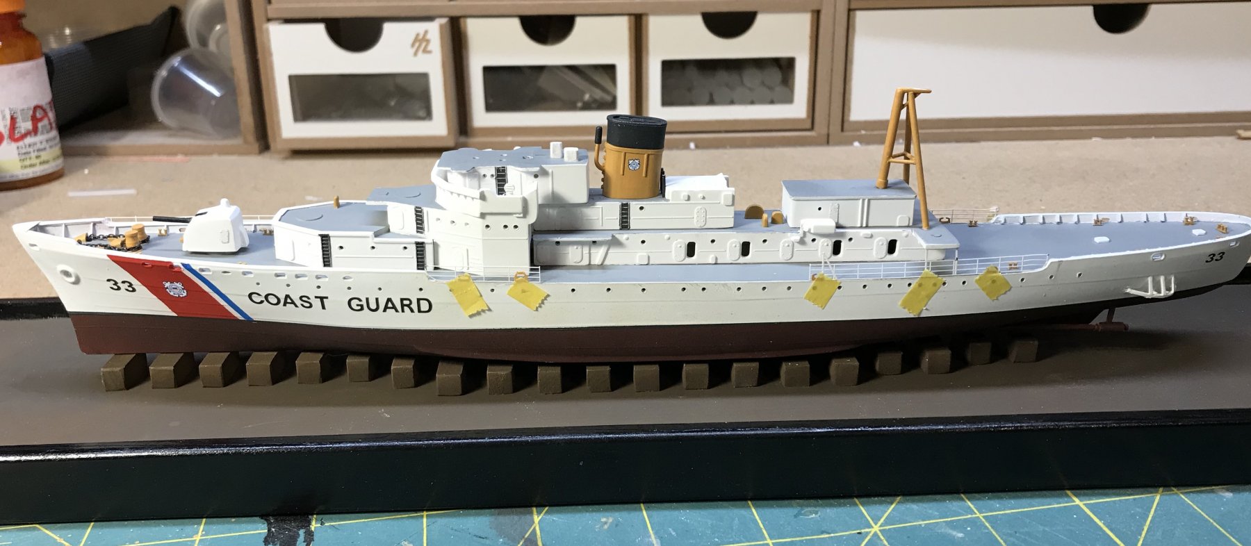
The display base is ready. ( I’ll build the clear cover last, once I know for sure the model’s final height.) I am decalling the hull now, so I can then flat coat it before attaching it to the base. The red is painted, the blue stripe is from an old Lindberg Patrol boat decal sheet. The rest of the decals are from the Alliance Modelworks 1/350 USCG decal set. ( I am really impressed with the quality! )
-
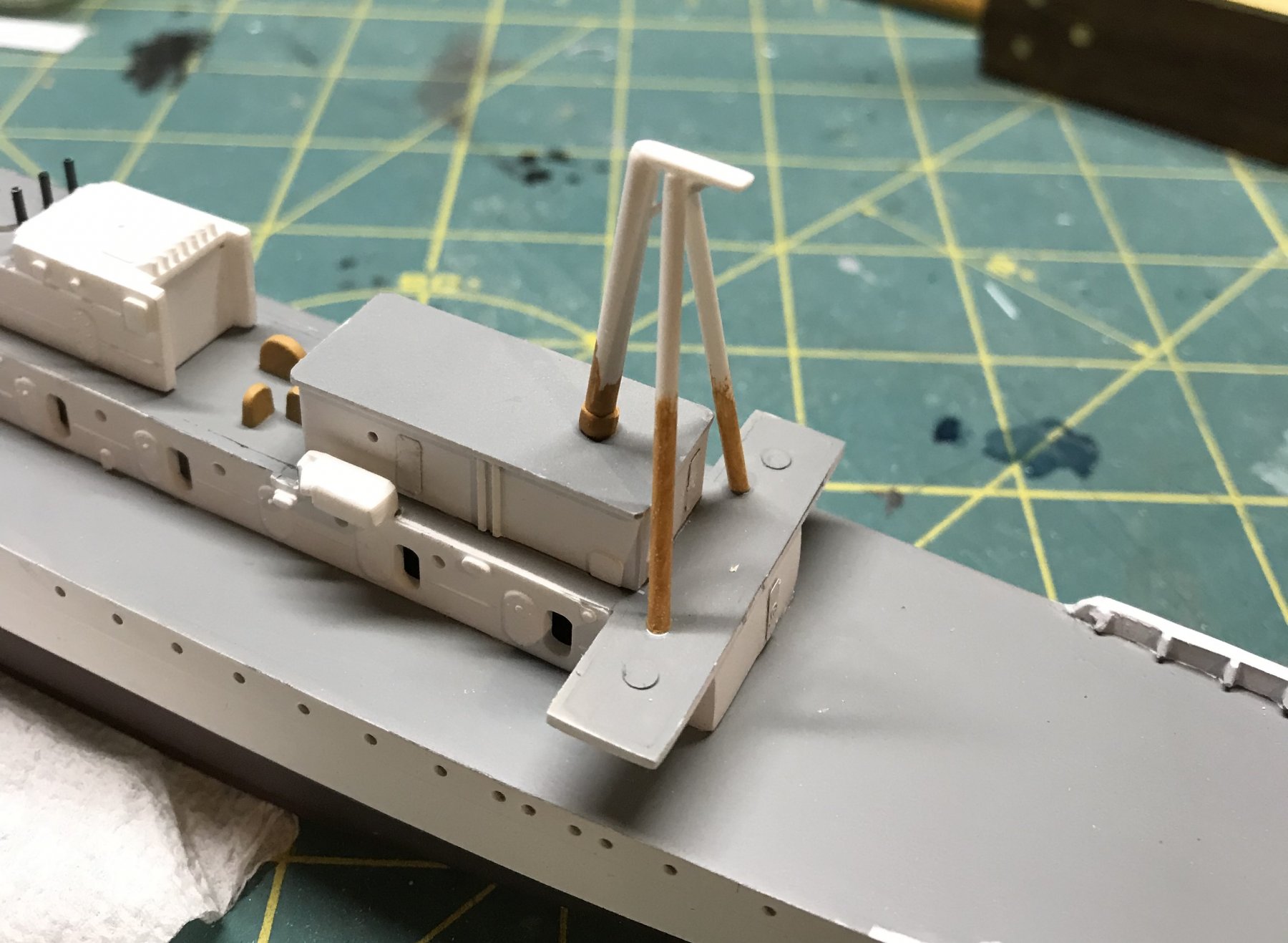
Thanks, Tim! Though I don’t think I would go so far as to call the Revell kit “nicely” detailed... -😎 Tonight I started work on a new tripod mainmast....