HOLIDAY DONATION DRIVE - SUPPORT MSW - DO YOUR PART TO KEEP THIS GREAT FORUM GOING! (89 donations so far out of 49,000 members - C'mon guys!)
×

niwotwill
-
Posts
596 -
Joined
-
Last visited
Content Type
Profiles
Forums
Gallery
Events
Everything posted by niwotwill
-
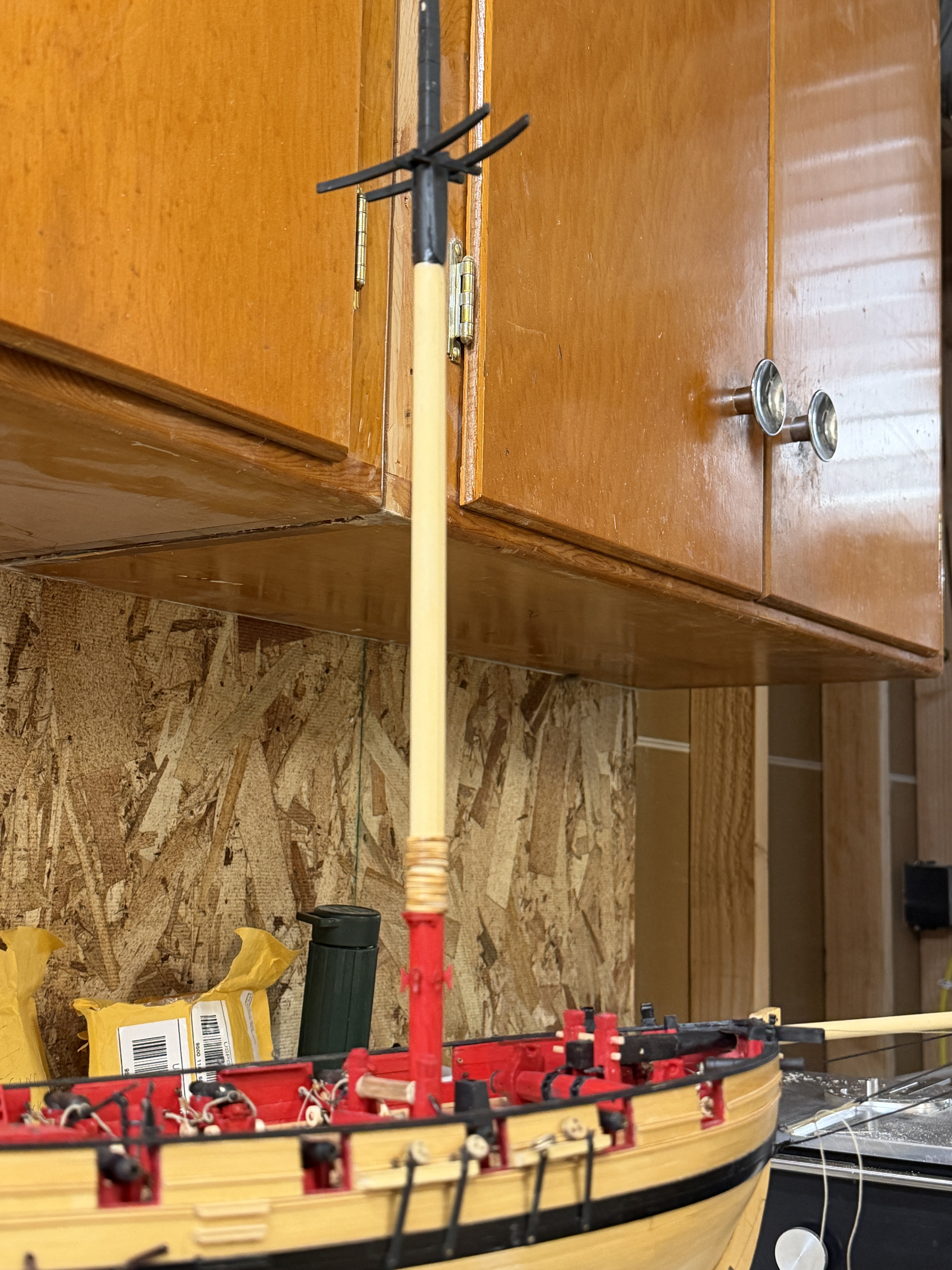
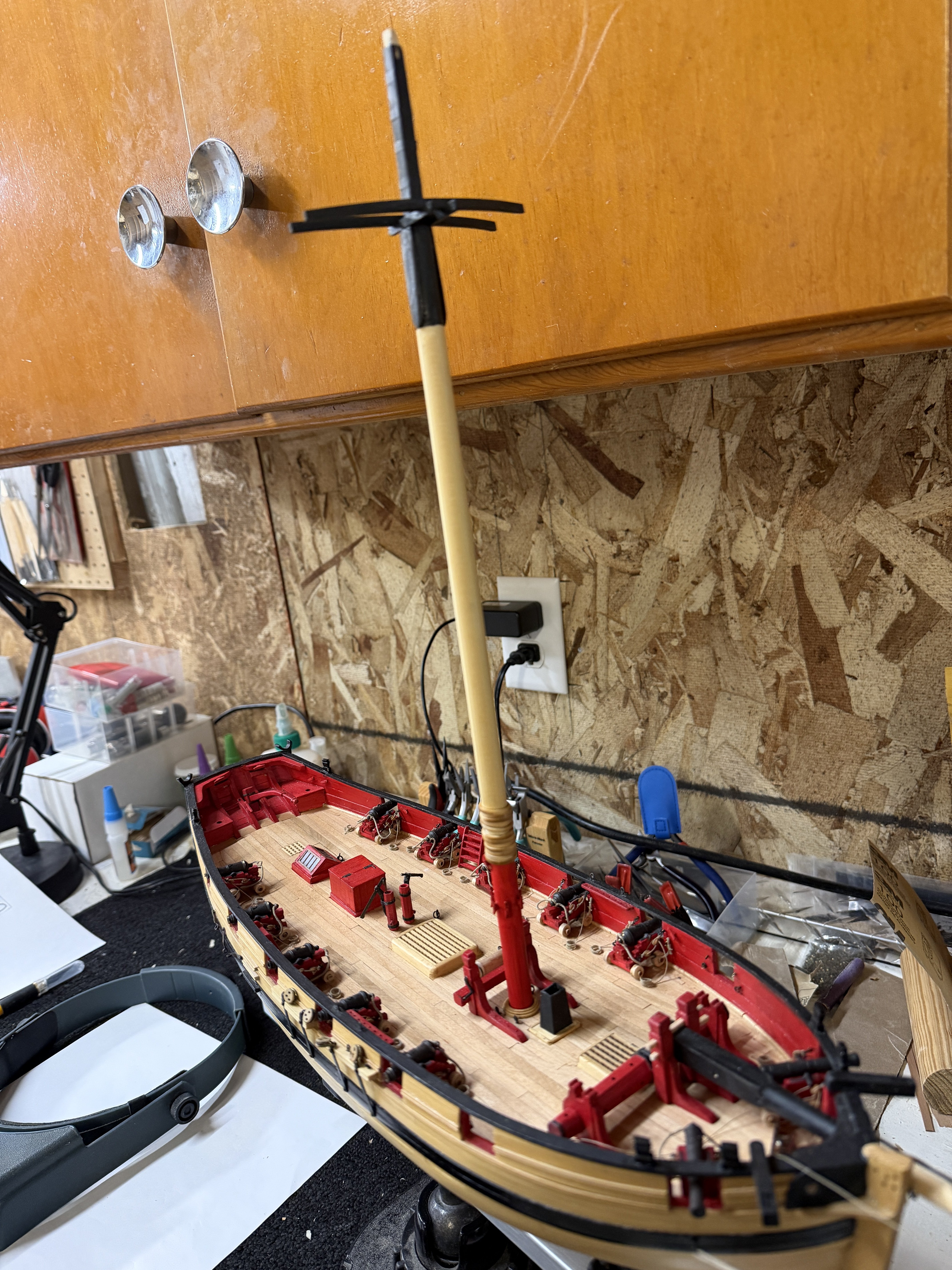
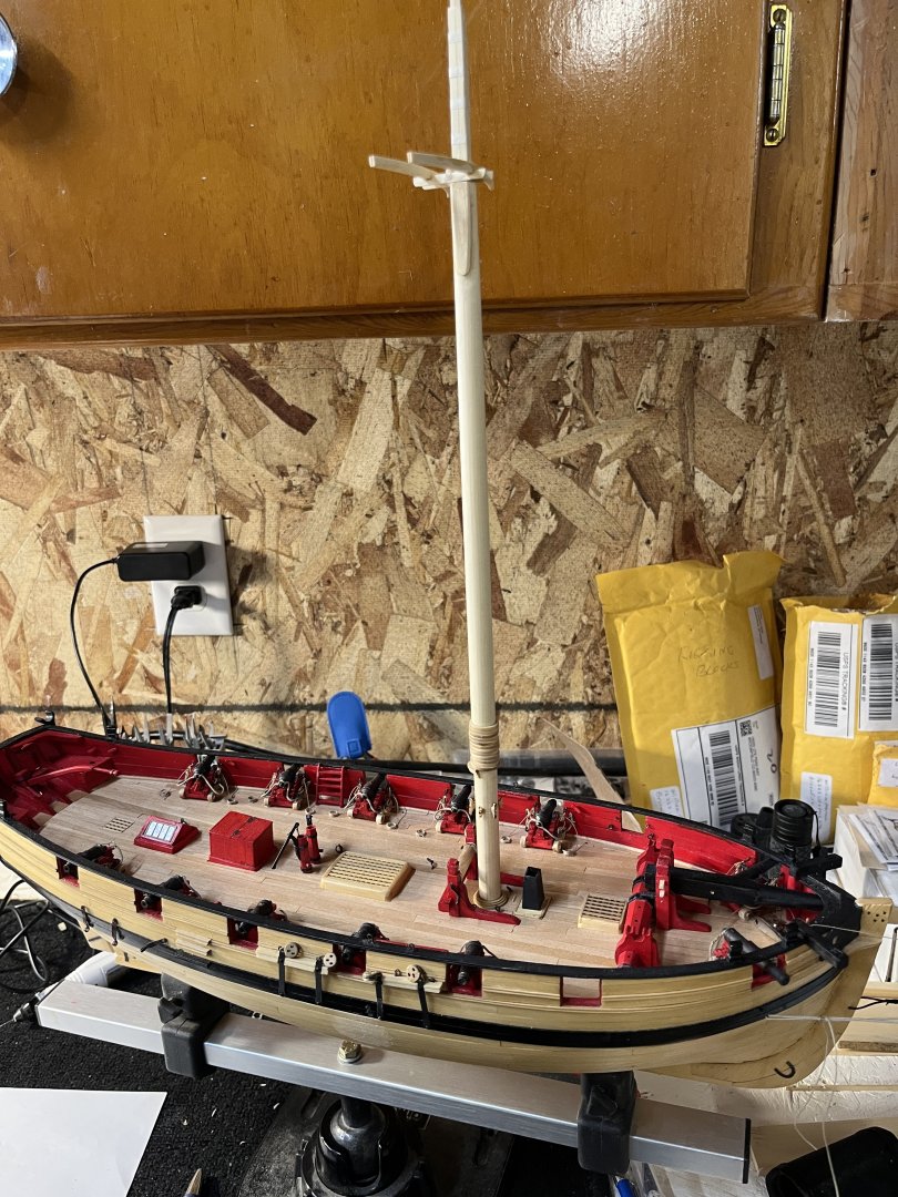
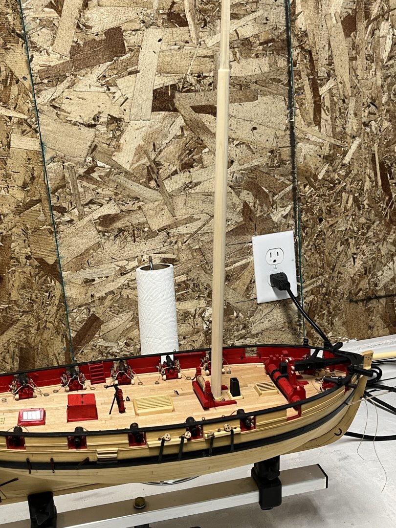
 Lower mast was completed last night so now on the to the upper mast and not much to report except how good it looks. No work today except for taking down the Christmas tree and decorations ending the season.

-
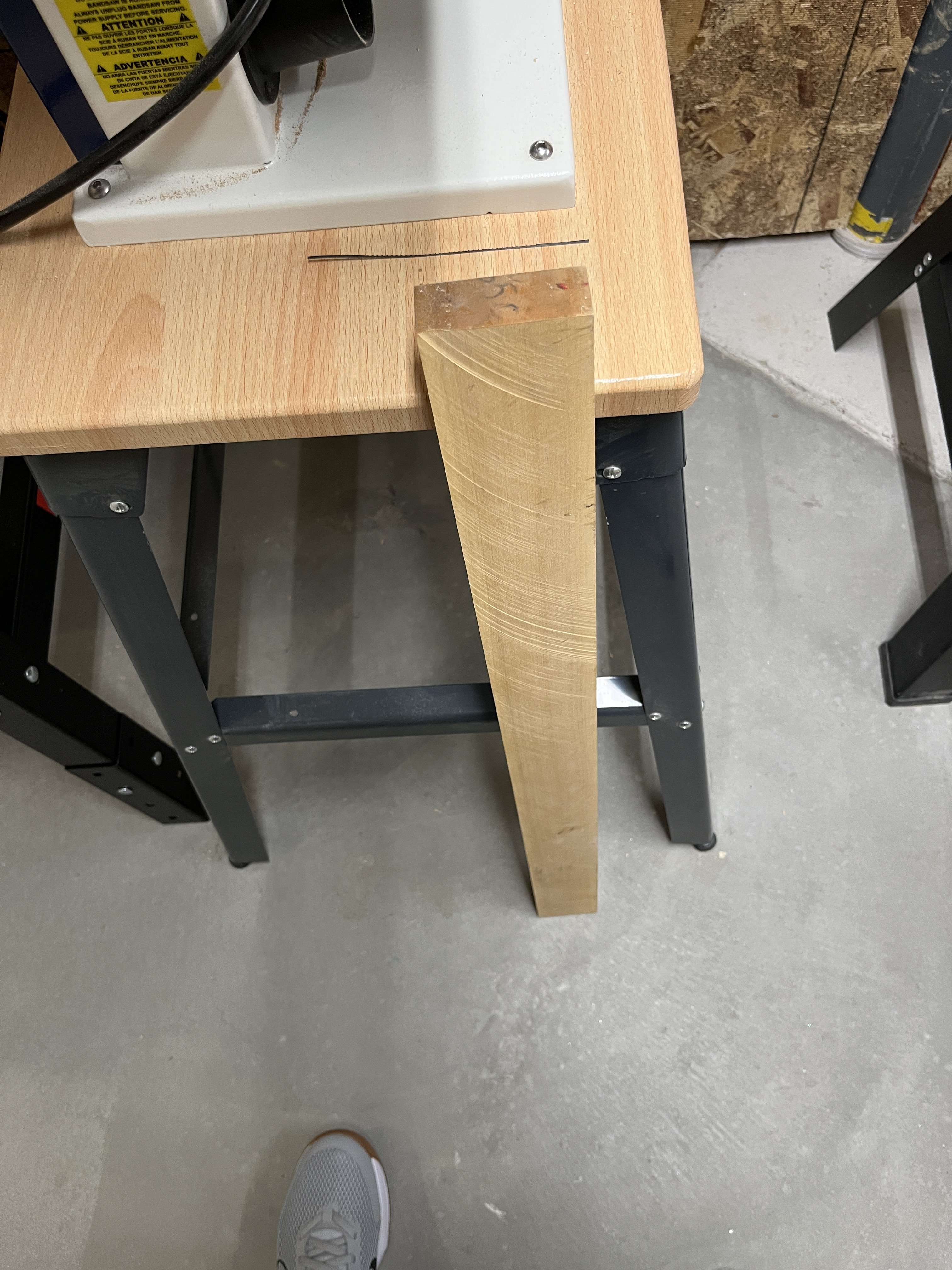
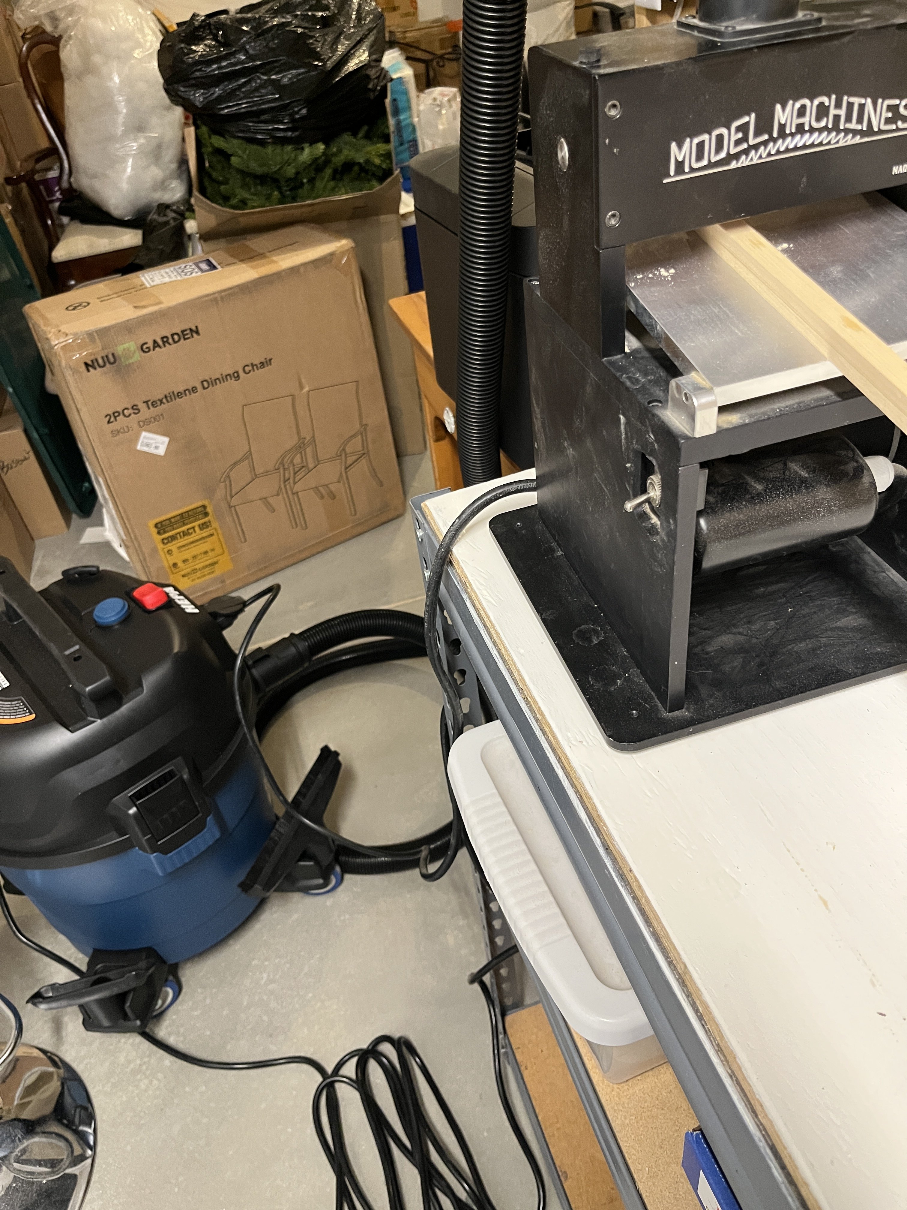
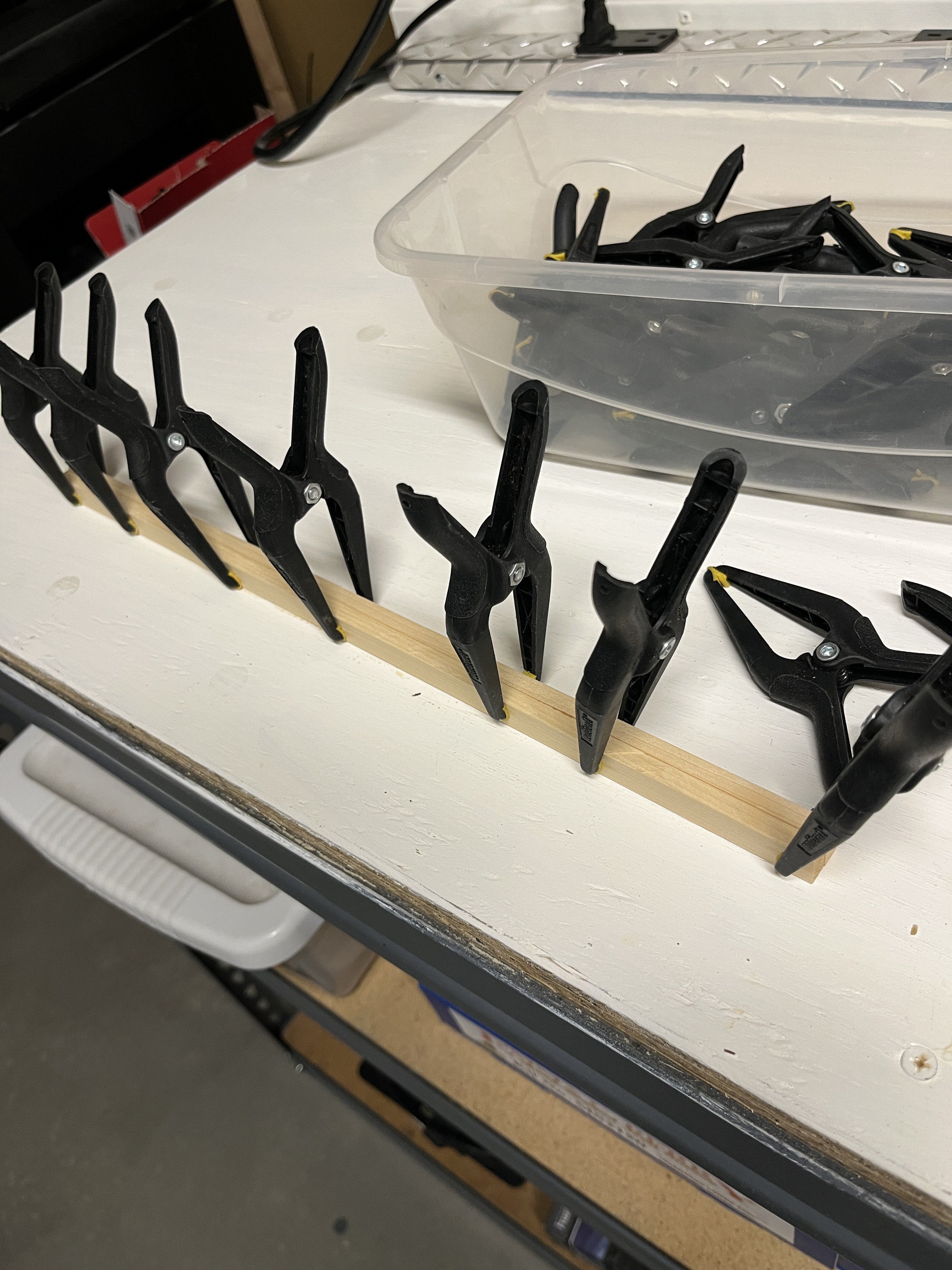
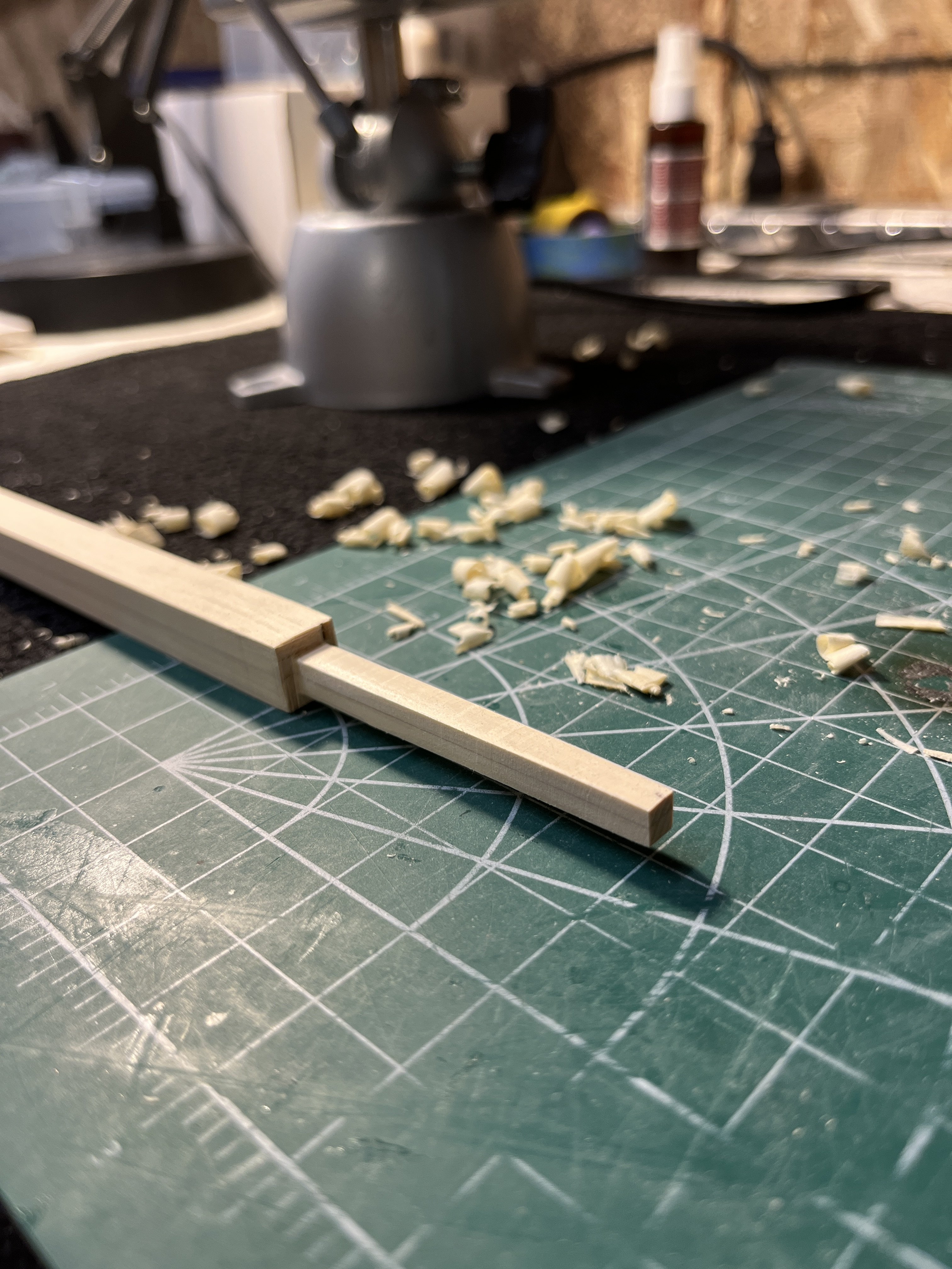
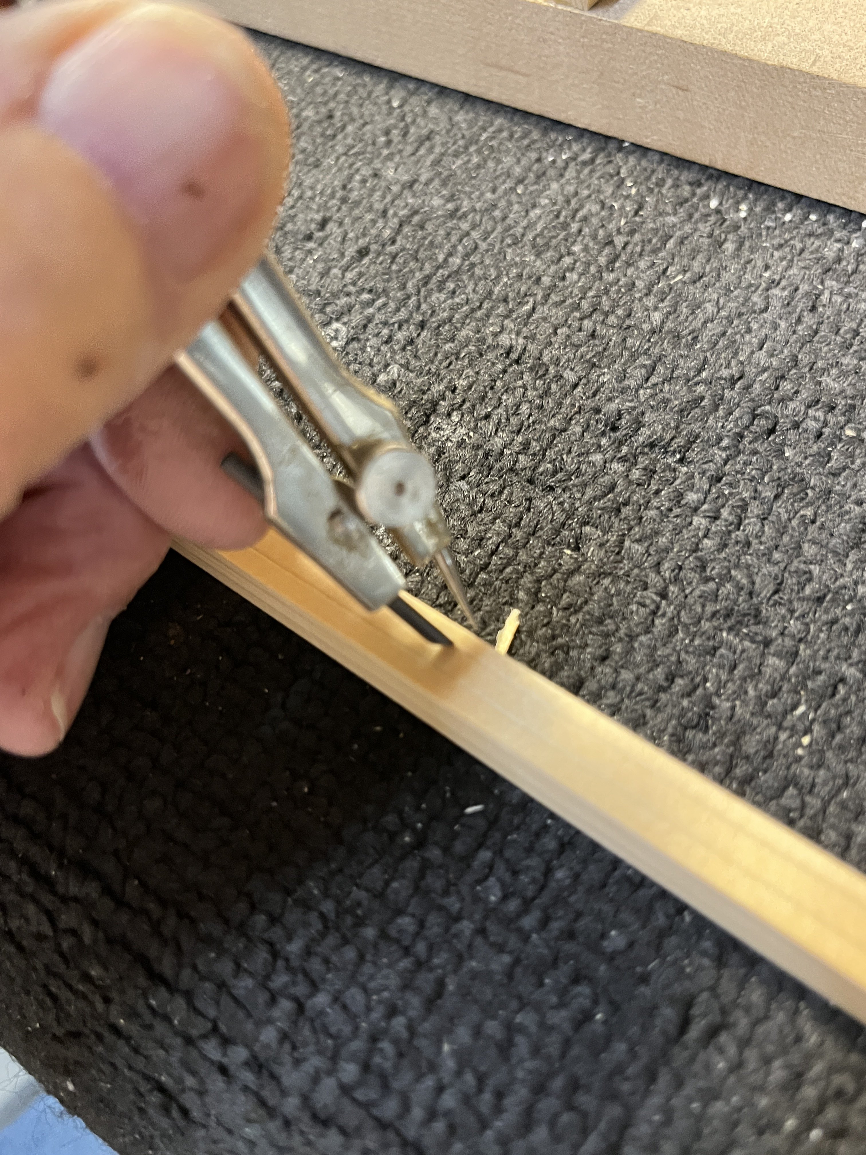
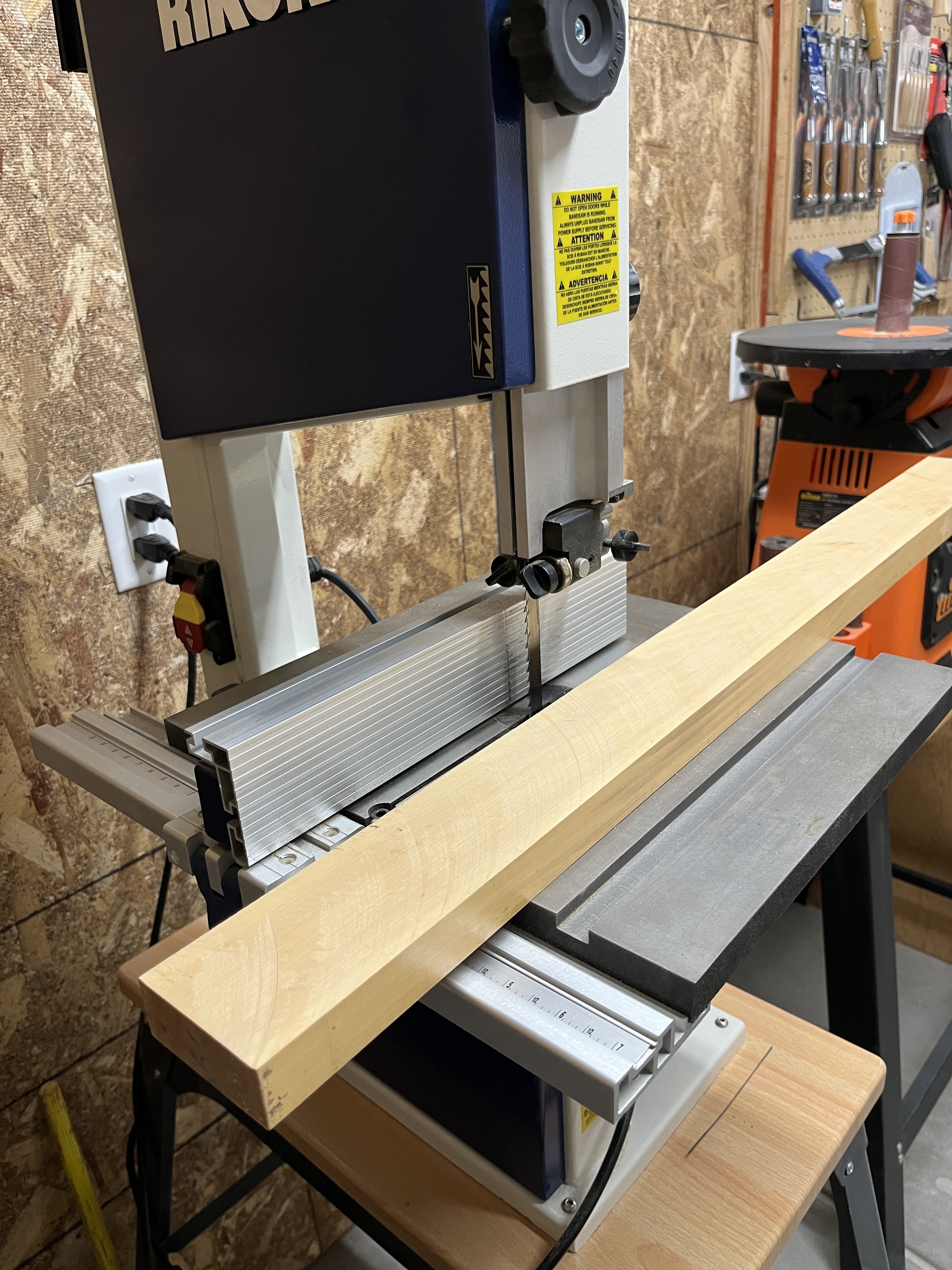
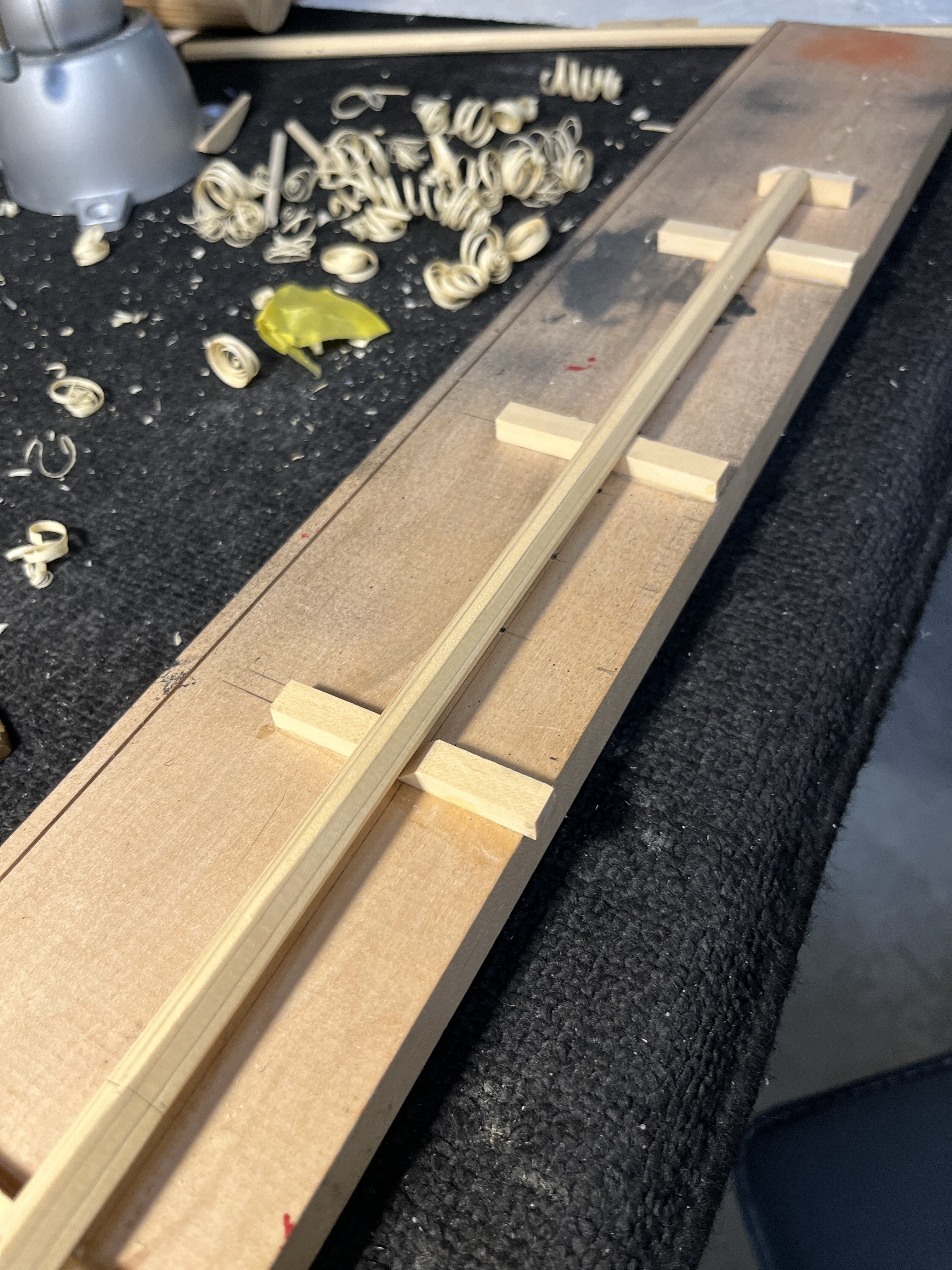
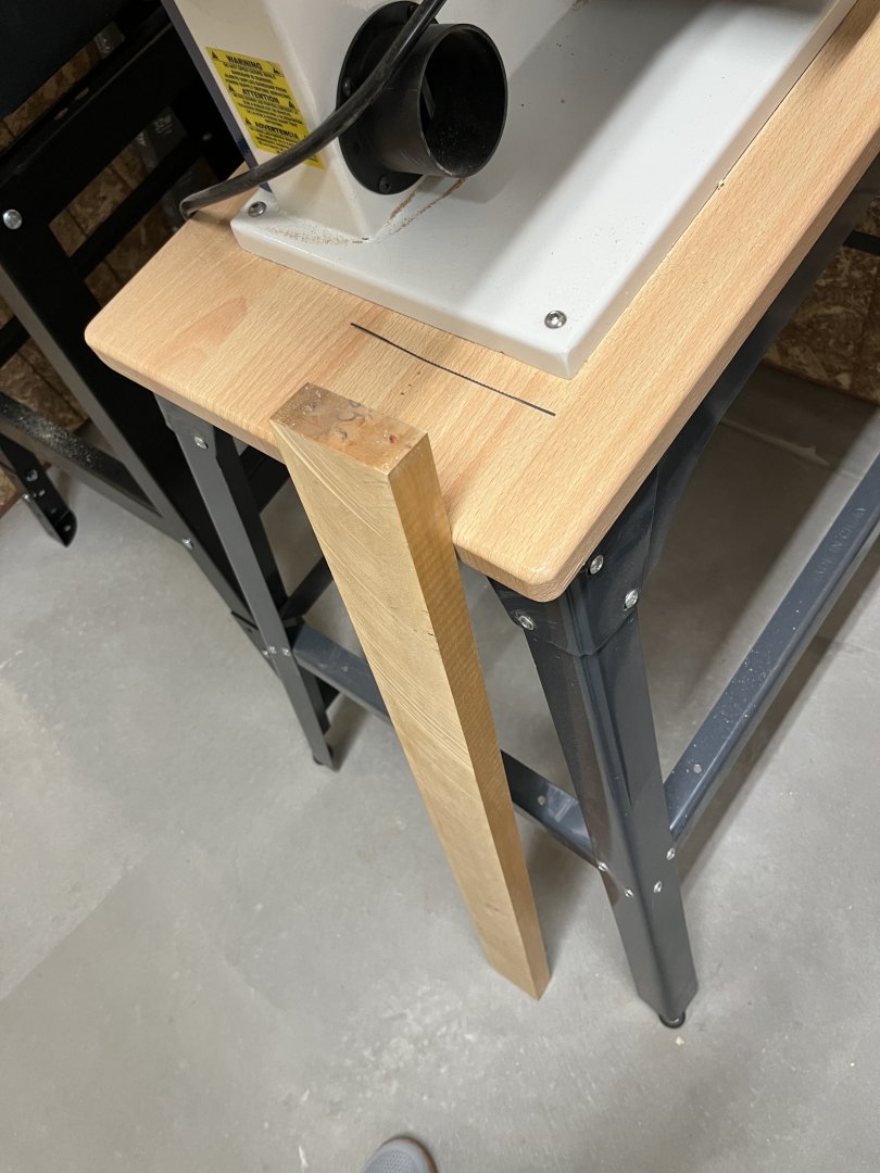
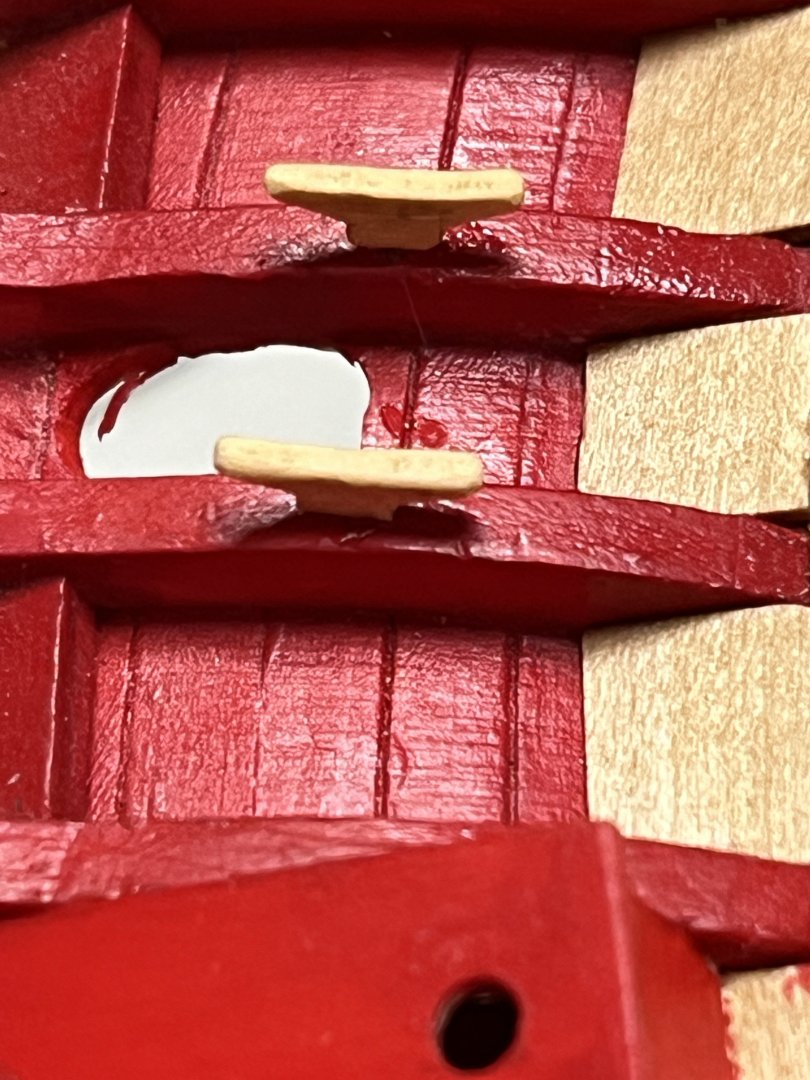
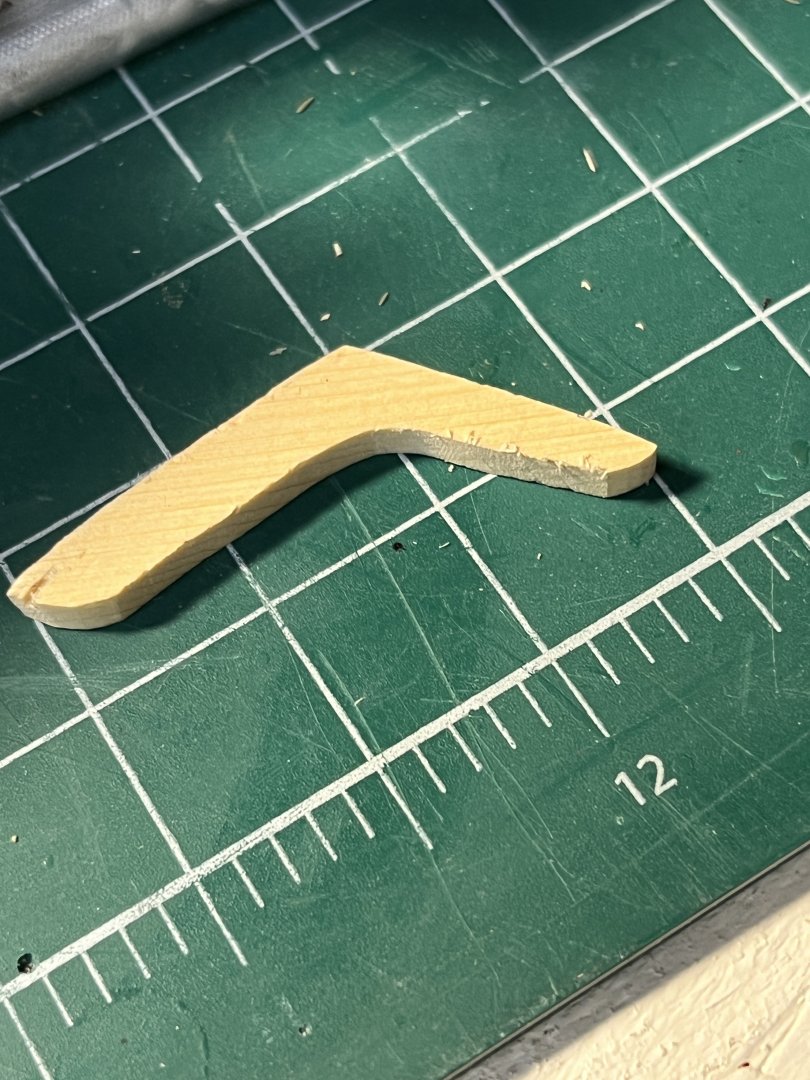
Now where was I? Oh yeah I needed to make the lower mast. Started out by finding I didn't have the wood. Needing a 5/16" thick AYC or boxwood which I didn't have left me two choices 1) ripping boxwood plank n wasting a large piece of wood for such a small part or glue two pieces of 5/16" together after ripping and cementing together making a 5/8" for the mast . Using the Byrnes sander making a piece 5/16" square r Ready for the square portion of mast Next using the 7/10/7 method to make an octagon ready for the lathe. using plane cutting to the marks and into the lathe into the finished mast


-
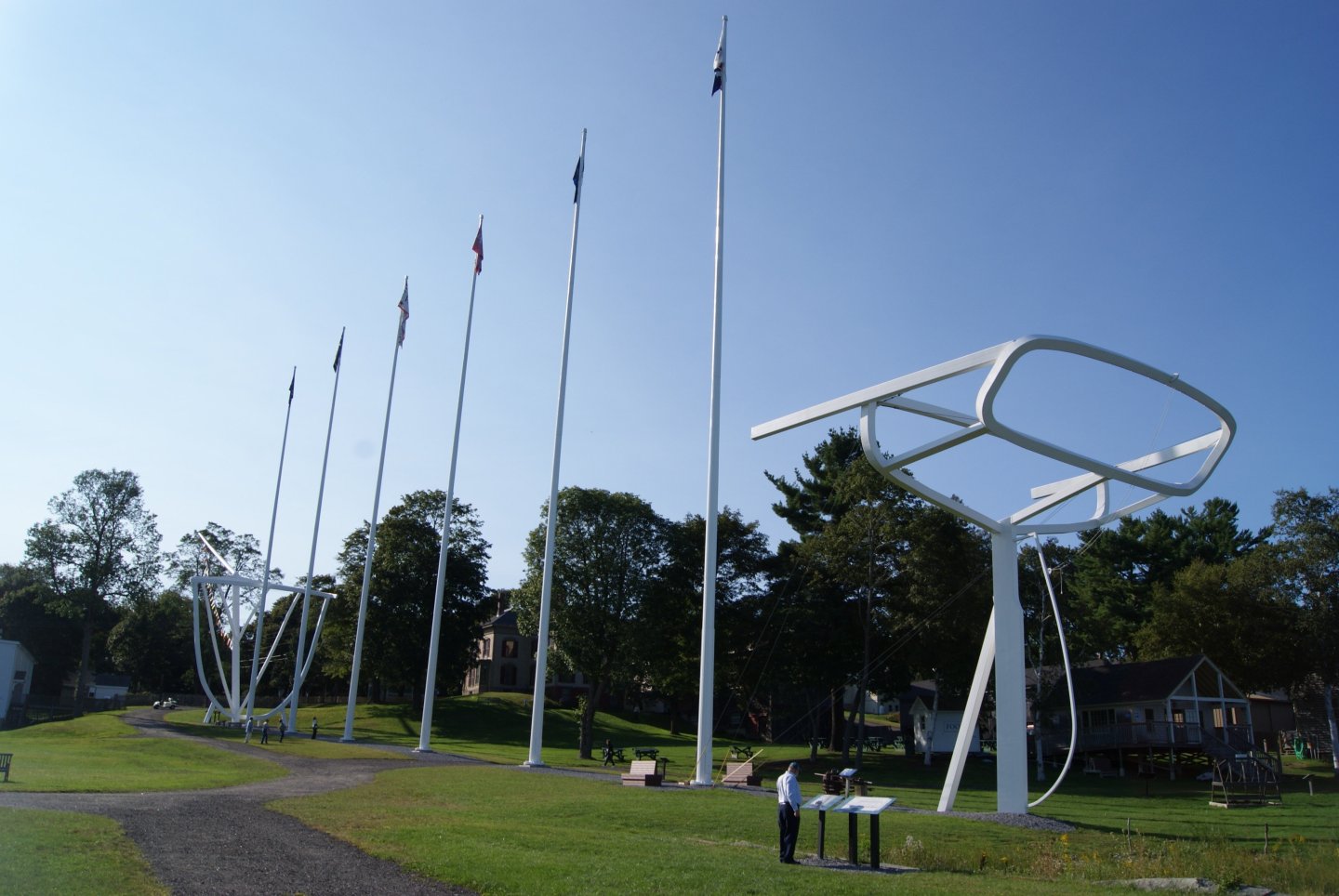
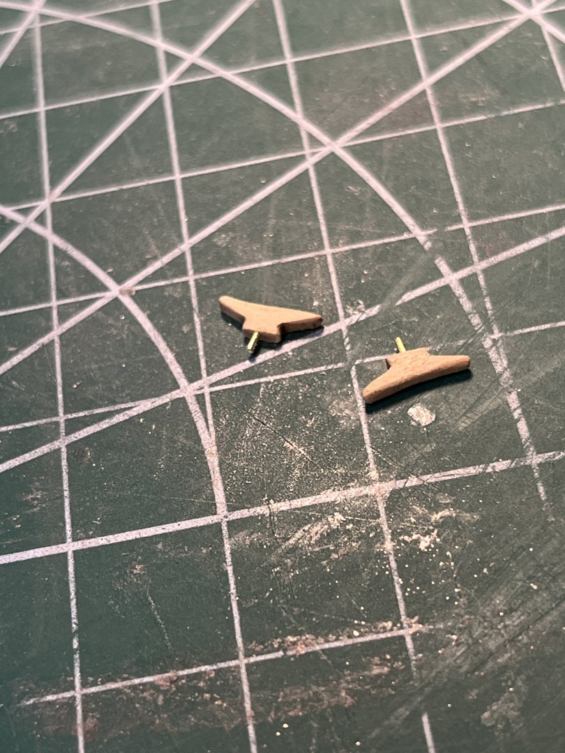
First batch of birthdays and holidays (Wife's on 10/22, Brothers on 12/6) behind me so now on to the Cheerful. Worked on the trees before the mast as I think it will be easier to make the mast fit the trees rather than trees fitting the mast. I copied the plans and glued to wood for part. Using the scroll saw cutting the image leaving enough too finish with the disk sander. (I'll put a new sandpaper) next using the oscillating spindle sander to finish the parts inner curve. Like other logs where the used a mill to cut the slots into the cross pieces, why with others success why reinvent the wheel, I did the same process. Using four pieces of material glued together so the protecting the inner pieces from chipping as the cutter existed. T The parts where assemblied on to of the plans image. I left the center cross piece long on purpose to file it close to the adjoining part. When the glue dries I sand the center flush to the sides. With to trees done I'll move on to the mast. Gulp


-
Just thanking everyone for following my Cheerful log with all the comments and likes.
-
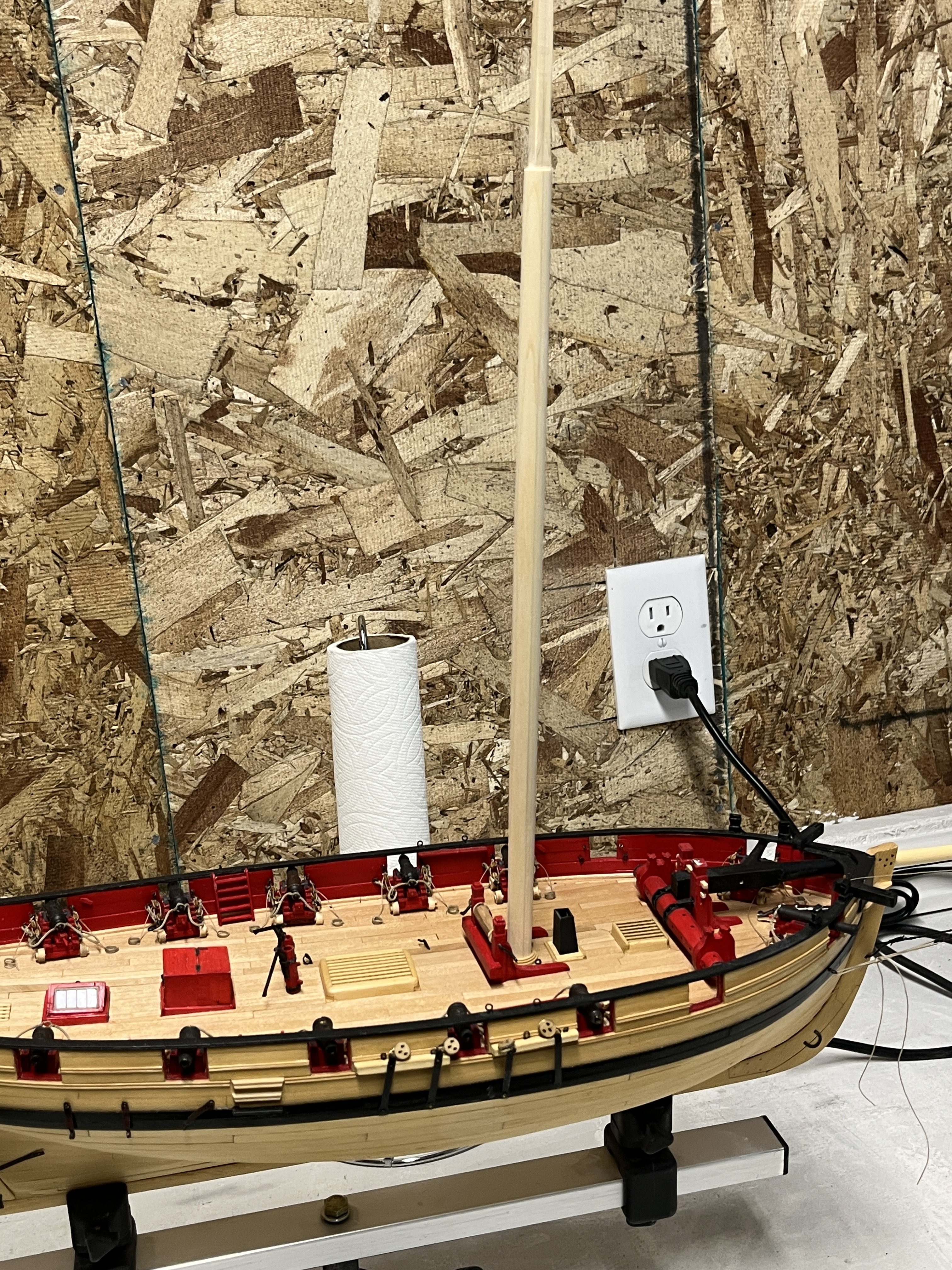
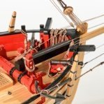
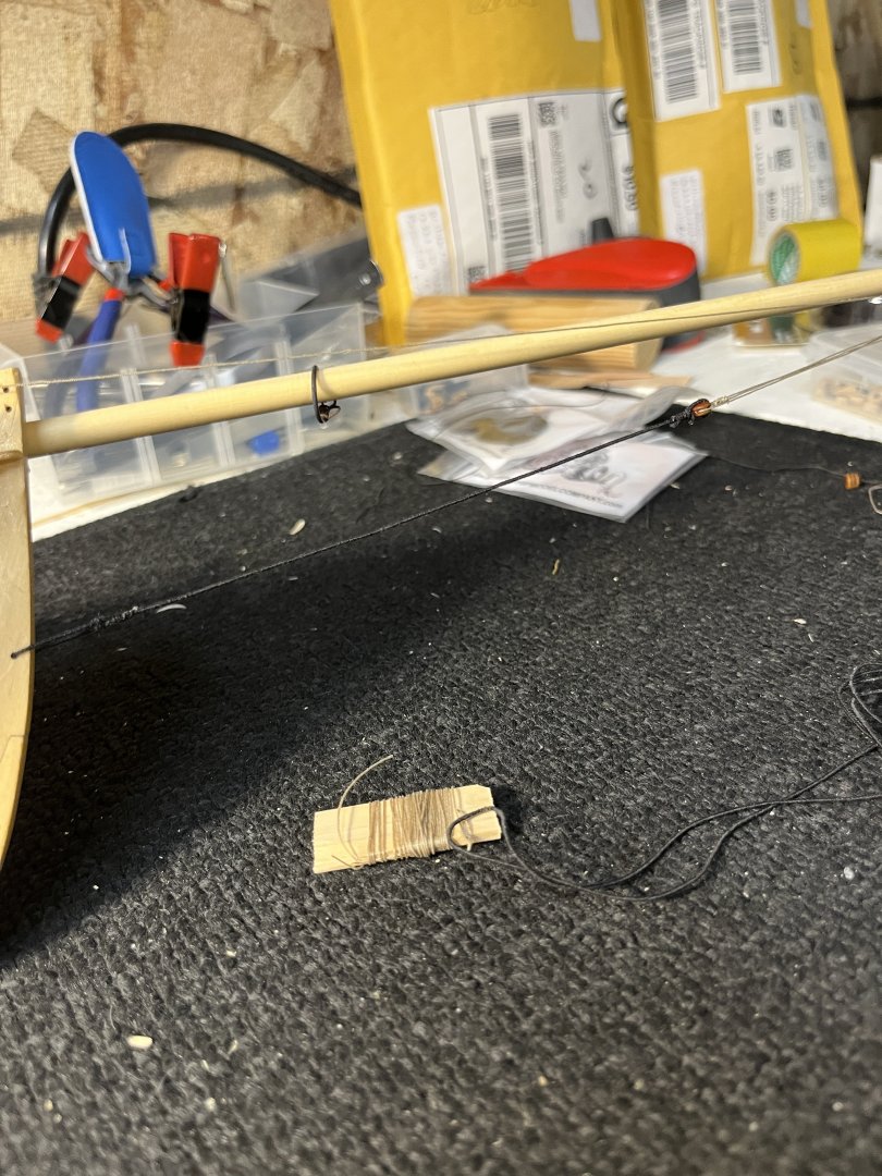
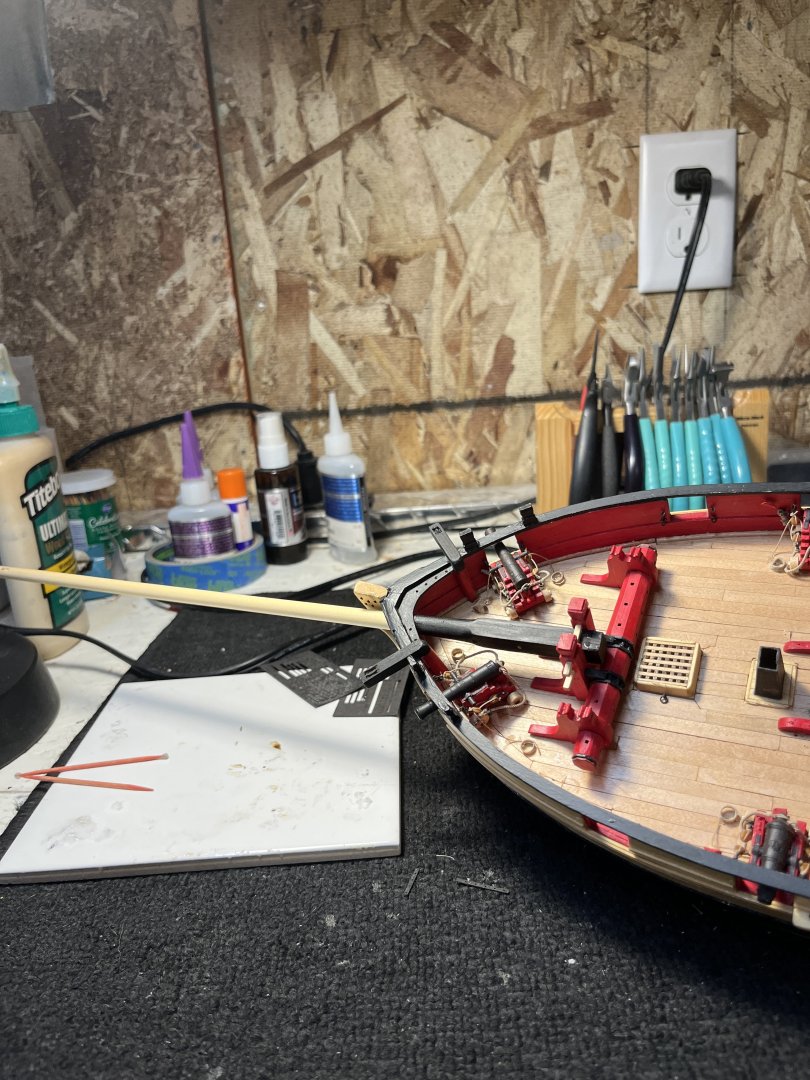
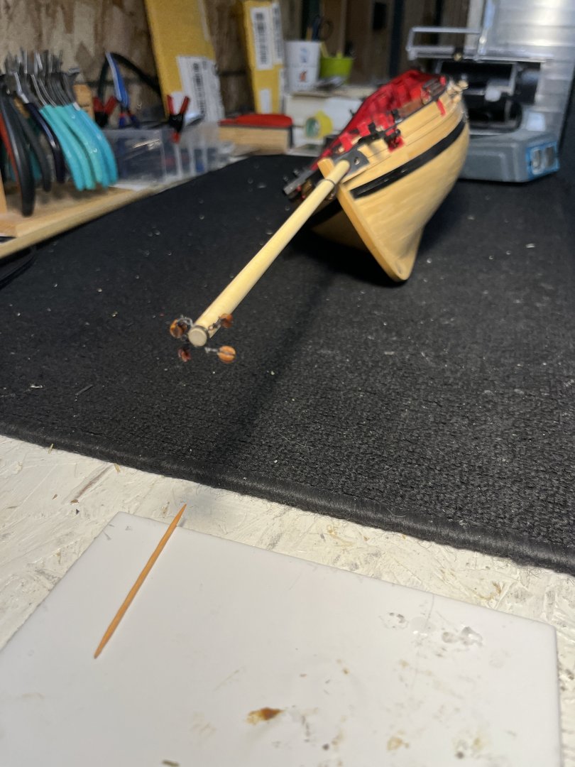
Finishing the bowsprit by adding the simulated sheave added at tip. Placed the bowsprit in my Proxxon lathe tapering from the square section to the tip. While in the lathe I filed tip with a small file. The metal (simulated) band was added to tip with 4 holes for the blocks. That all done I had to carefully finagle the blocks through the hole. Adding the bowstrip step and aligning such that the square rod could be pushed into the square hole. Now the posttion of the bowstrip and winch could be determined I glued them in position. This done I started the rigging process first the bobstay tackle and bobstay guys were rigged. Now with this done lets move on to lower main mast. I didn't have a piece of wood long enough so I have a slab of boxwood that I planned to use on 1776 Washington Galley later but that will be later. Next more about ripping the slab to make the beginning of the lower mast. Its been quite awhile since I ripped wood on my band saw so Its too late starting a long process so I leave it until were home from Thanksgiving with friends in Phoenix. I had bought several of these boxwood slabs from the Gilmorewood company in Portland, Oregon. Its hard to cut into a slab to used in another project for one mast but It is for a good use and I have more.


-
Thanks Glenn for the suggestions. Looking at the rigging of the boom I see why you suggested and why. Thanks to all who looked and commented on the Cheerful to date. Chapter 11 complete up to bowsprit and mast shape wood Bowsprit and mast rig bowsprit rip wood for the mast finish mast touch up paint use drafting compass to draw 7/1/7 lines on wood r Shaping after squaring and drilling holes Add metal band at the tip with four blocks seized to the rings file hole in bulwarks to fit the bowsprit touch up paint On to the mast


-
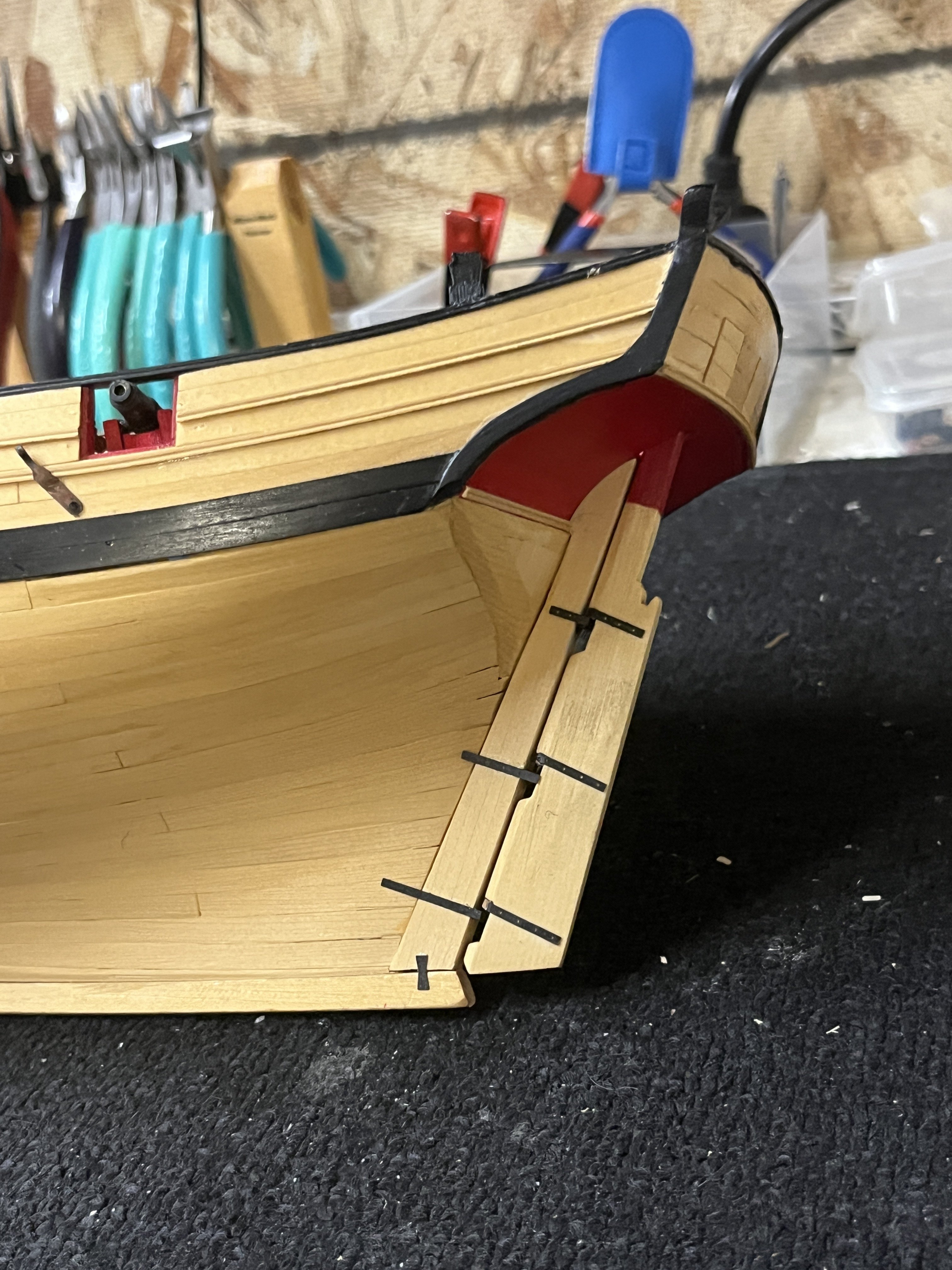
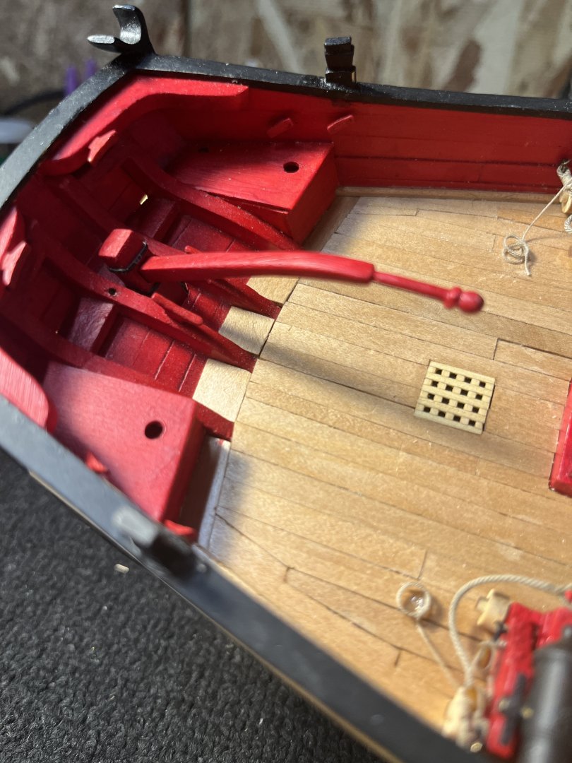
Chapter 11 consisted with the deck furniture previously recorded plus the rudder and tiller. The rudder had quite burn scar from laser cutting. Once the rudder was clean I followed the monograph with the side tapering. Thinking I would make the gungeons and pintles out of brass soon appeared to be more difficult than I had thought. All the curves on the hull were difficult to conform with the .015 brass. So back to the Syren kit for pintles and gungeons which was than I first thought. Going back looking at the pictures I noticed the nails were omitted. For another date after the mouth heals. Knowing that tiller would need to fit ahead rectangular hole I followed the suggestions in the monograph cutting a rectangular hole for tiller. The rudder and tiller were easier than many on the Cheerful. I panted and dusted the parts prior to gluing. Being carful noting glbarlow warning of parts not sticking due to many layers of wop. With the rudder hung it was time to make the tiller. Using 1/8" material and shaping the end so that it fits snuggly between the simulated metal bands on the rudders head. On another site I saw how a metal rod was used for gungeon alignment allowing free rudder movement after rudder pintle pins slipped into the gungeons.

-
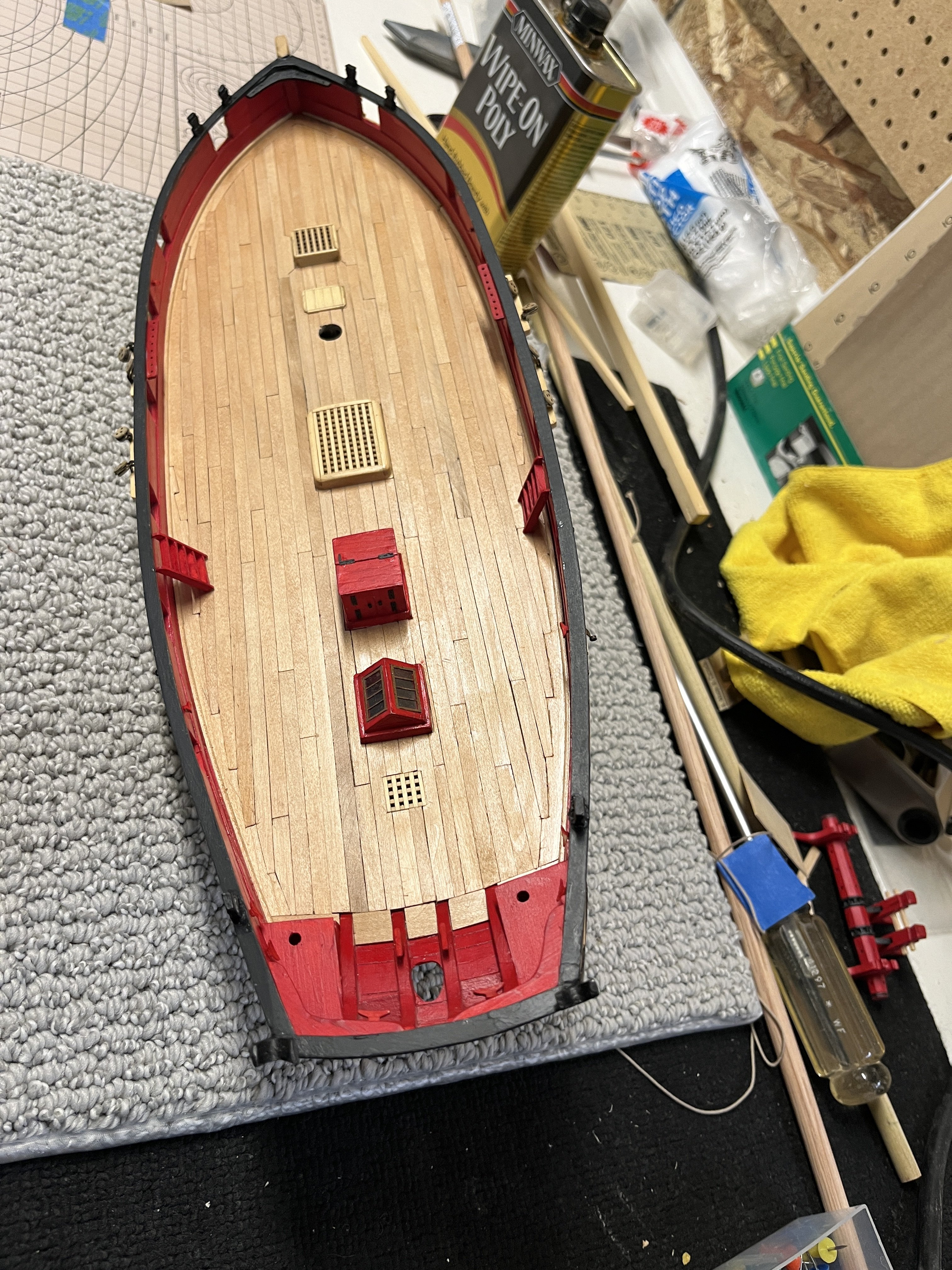
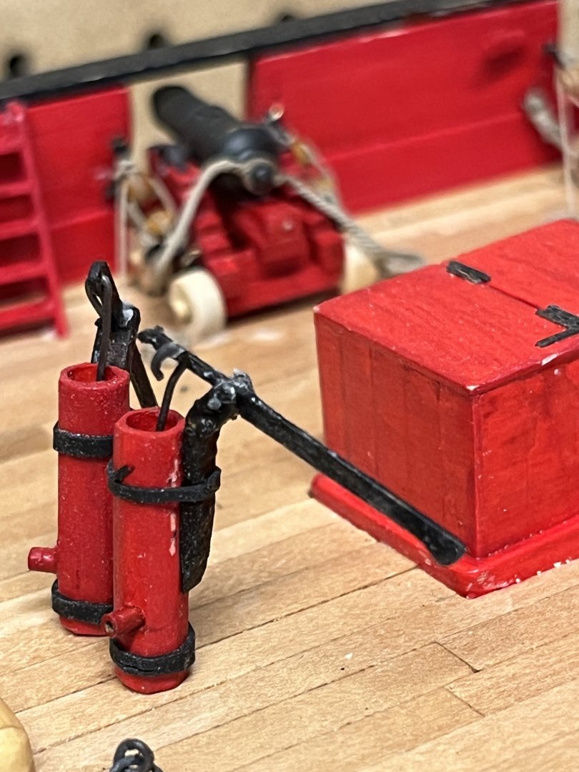
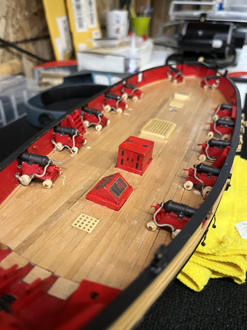
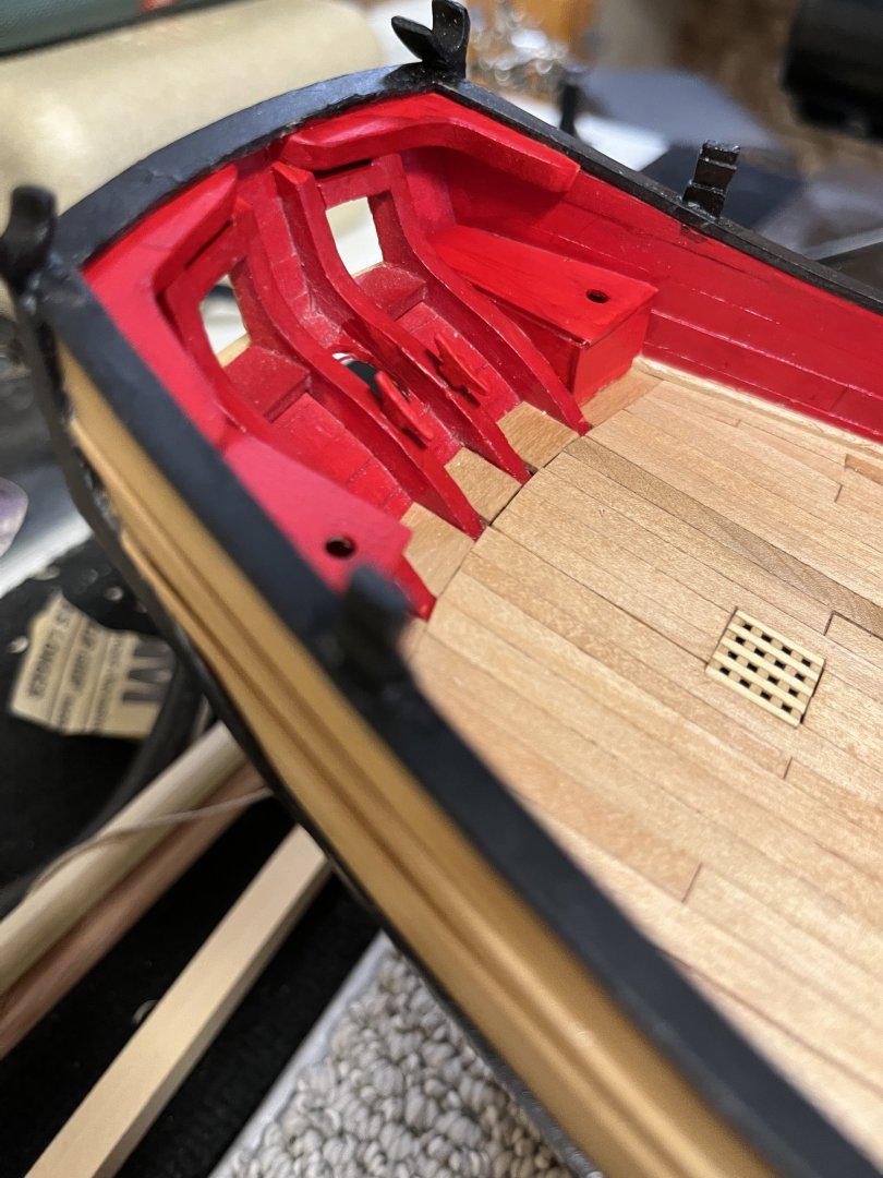
Nov 18th and the deck furniture made while on vacation June 2021. So to follow the build refer to sheet 2 of this log. The pumps made using Syren Model kits. I made the exhaust ports from brass tubing. You'll notice one of the pump handles broke when the plunger installed. Had to make a new handle and smaller wires. More Syren kits companion way, bowsprit, and winch. These kits are amazing not only in their quality but they give a very nice break for the slower tasks. Bowsprit completed but not glued to the deck. The winch completed but again not glued permanently . All of this brings me up todate with the postings. This gave me the time not to model as I've had the number 19 tooth removed in preparation for the bridge.
-
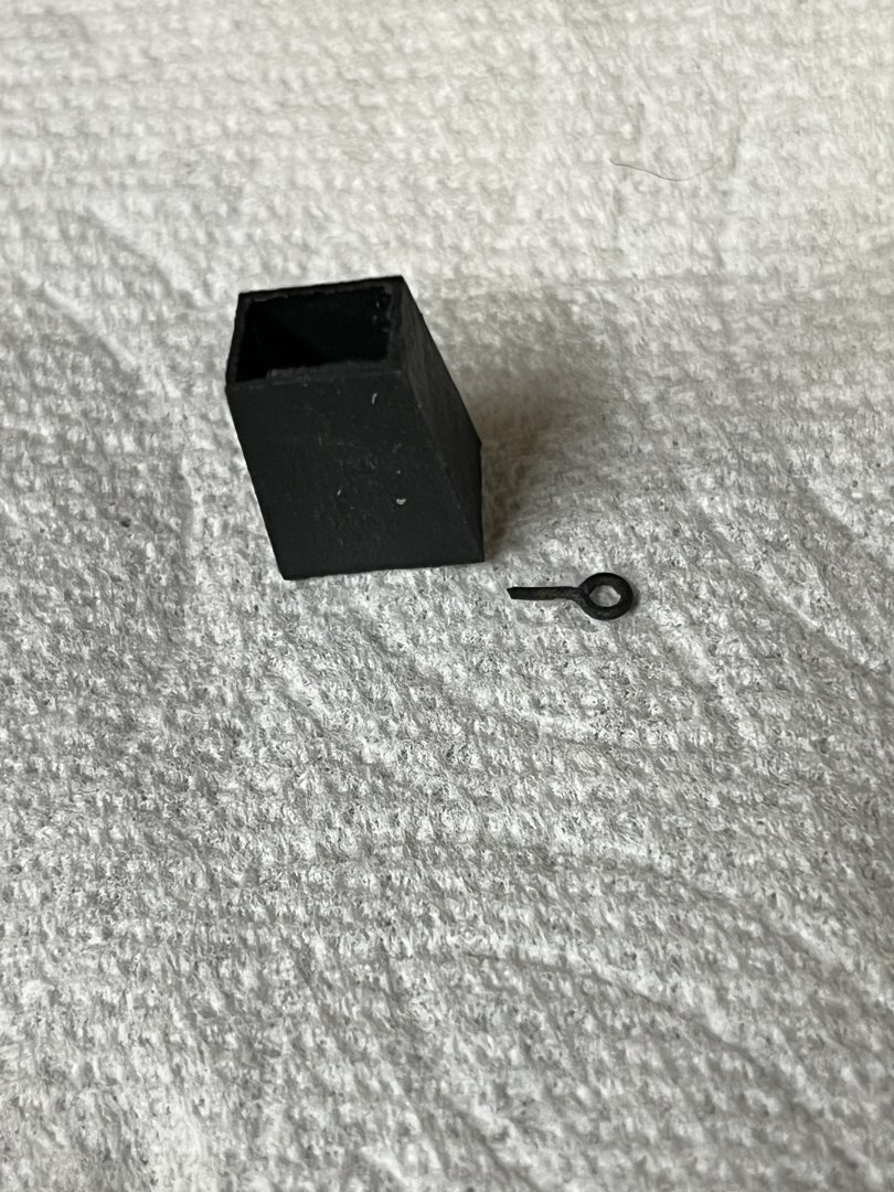
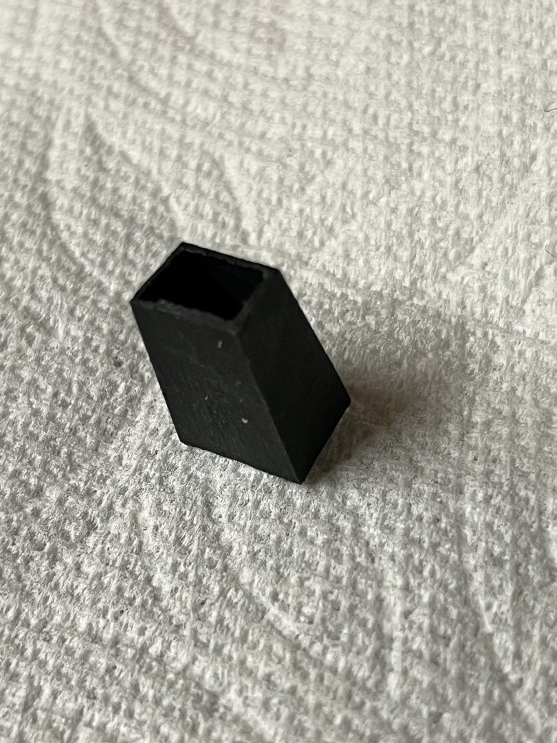
Today is Nov 18 and I completed the galley stack on July 6. The stack was made from a .015 thick piece of boxwood that had been planed from a .032 sheet boxwood. I originally thought a sheet of copper would be used in 4 pieces silver soldered together forming the stack. BUT the copper could not maintain a smooth shape from the soldering heat. Next pieces were cut from a brass sheet with the same results warping. Looking at the wood chimney didn't finish with sharp edges so more experimenting with the brass. The silver solder comes in an ejecting tube of soft, medium, and hard with corresponding heat. Now with 2 sides standing aligned and upright on a ceramic tile with a tiny dab of soft solder and the flame small enough to solder but not blow the sides over and flowed without warping. Now make the final sides closing the chimney. Sides 3 and 4 went without any issues and flowed the solder. All the sides were made from the plans and very carefully cut to maintain the edges. When I started making using very sharp jewelers snips. Its hard to see inside the chimney and I wish i'd put a light but two late now as it is glued ti the deck.
-
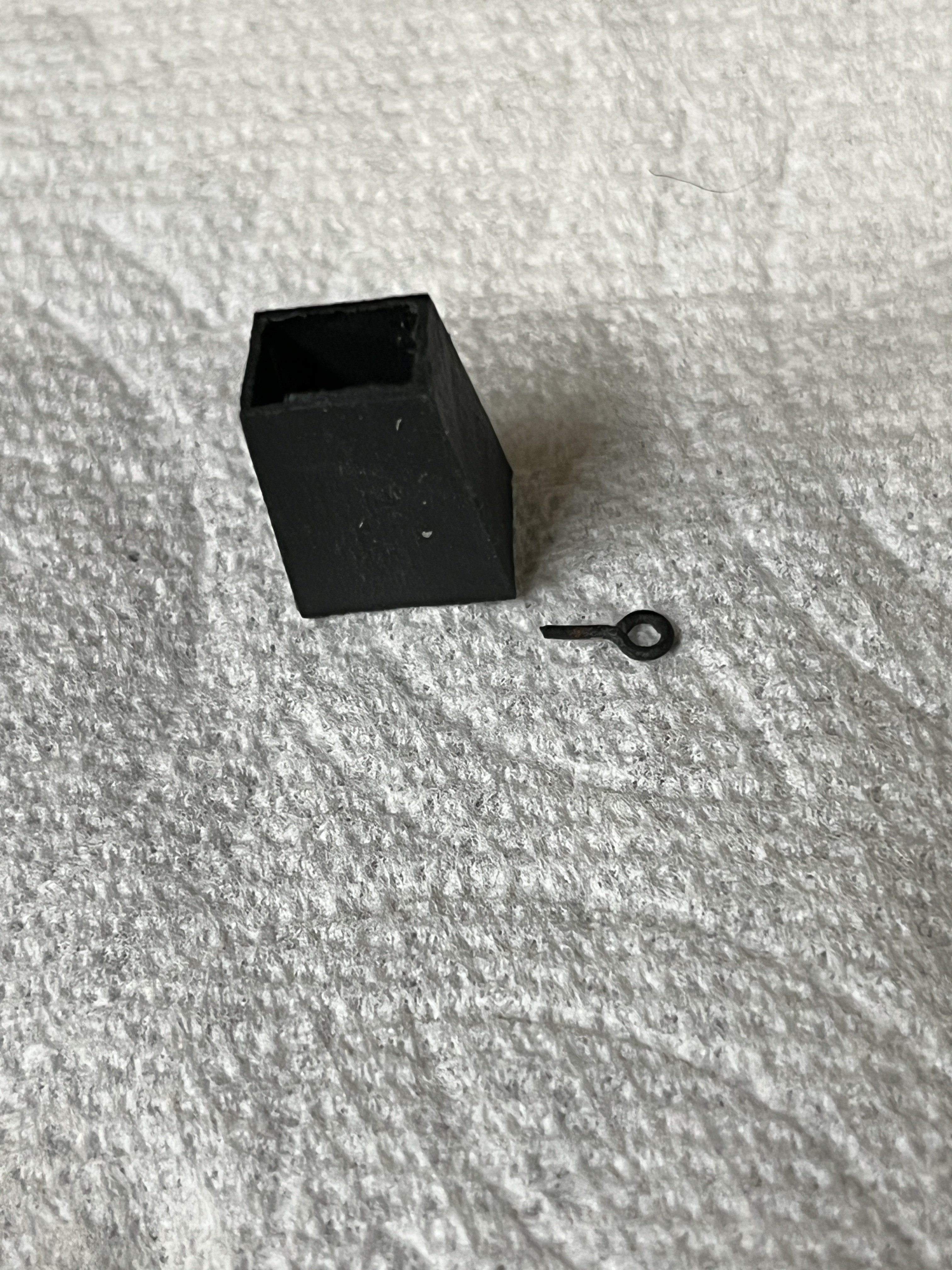
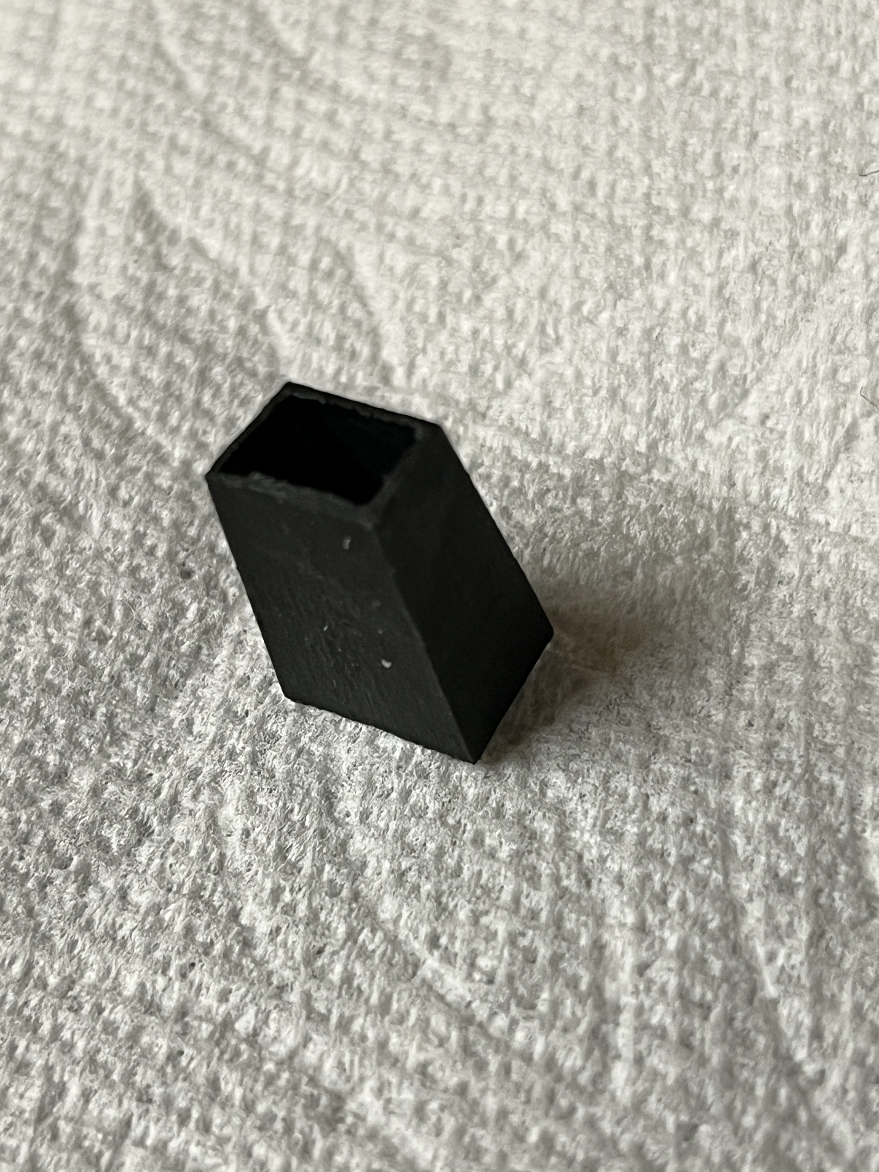
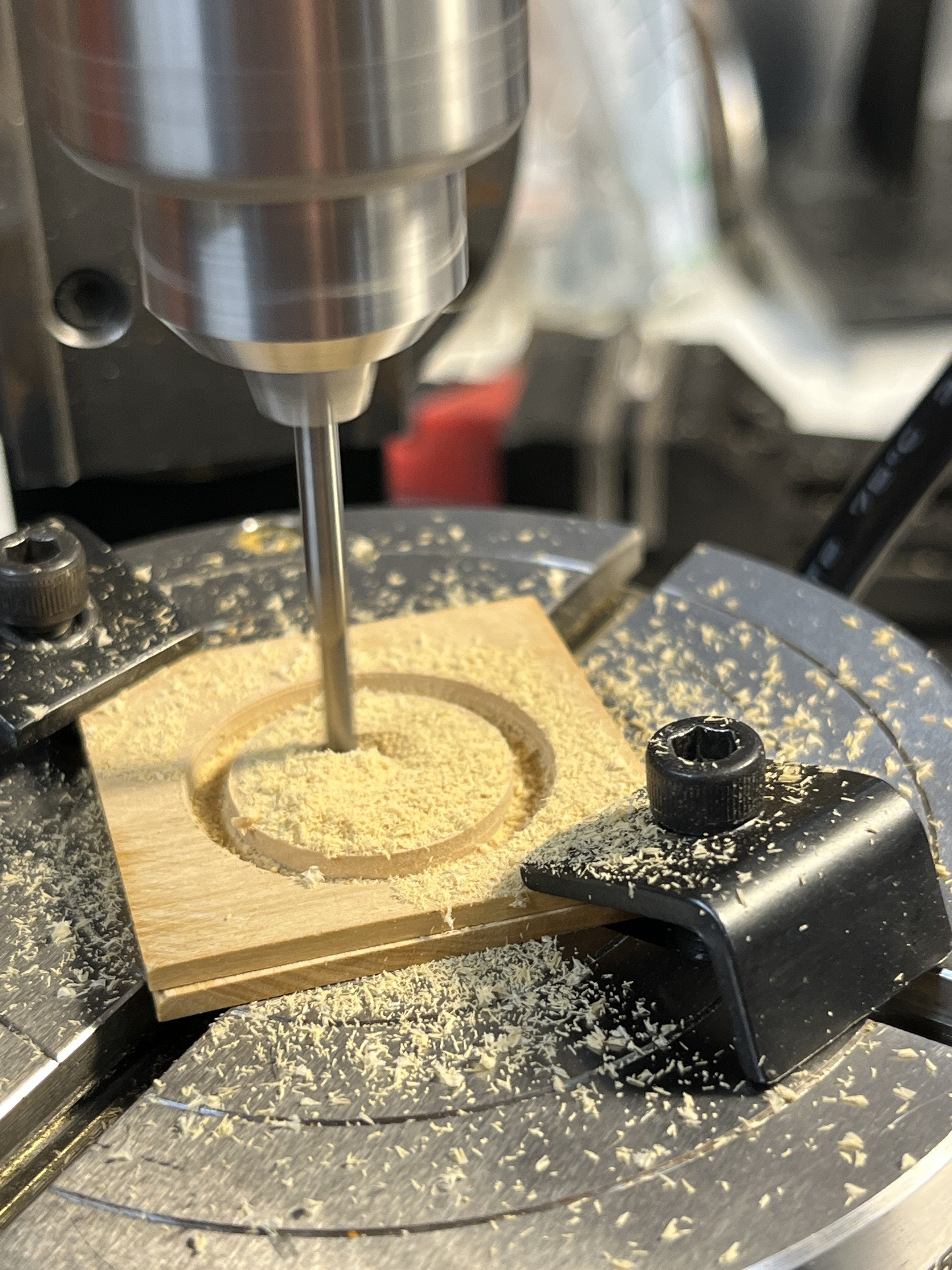
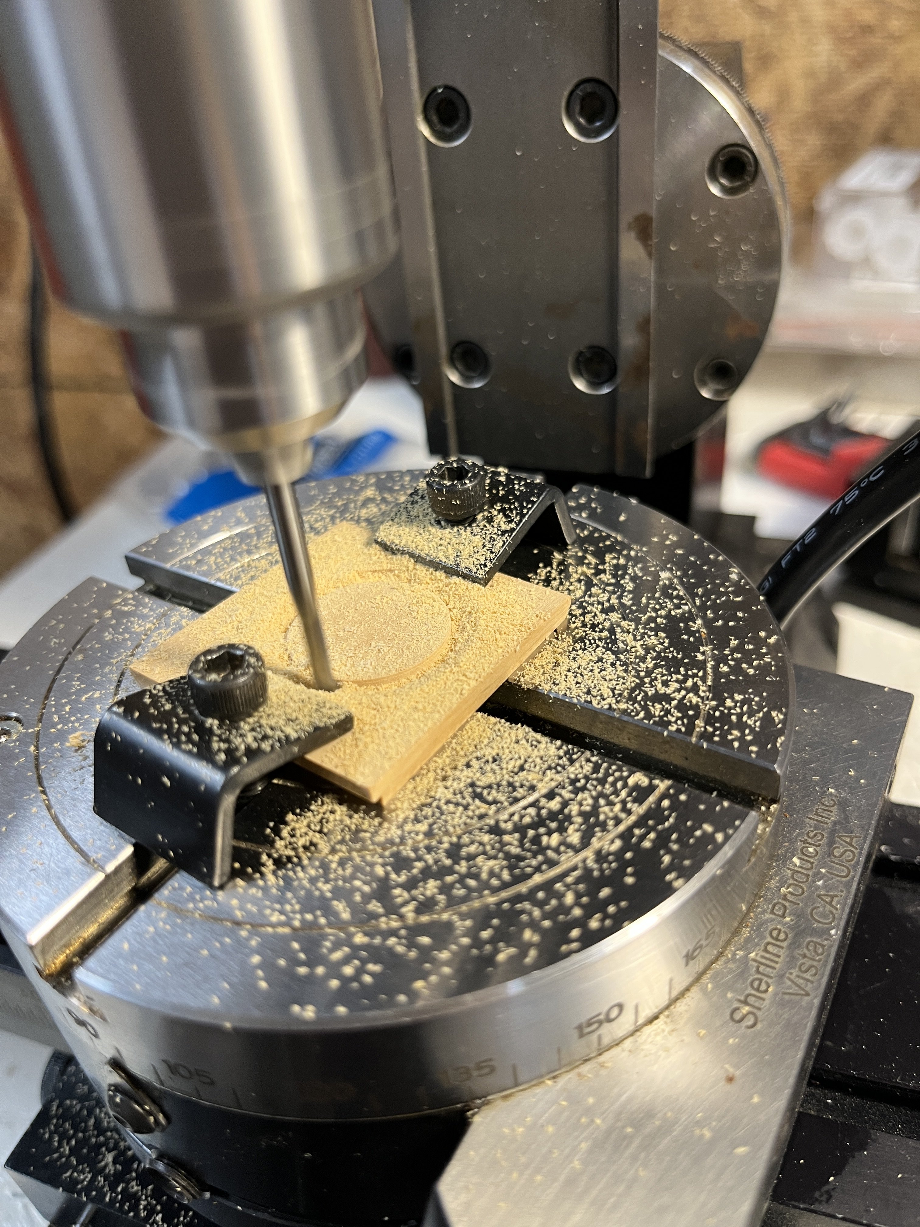
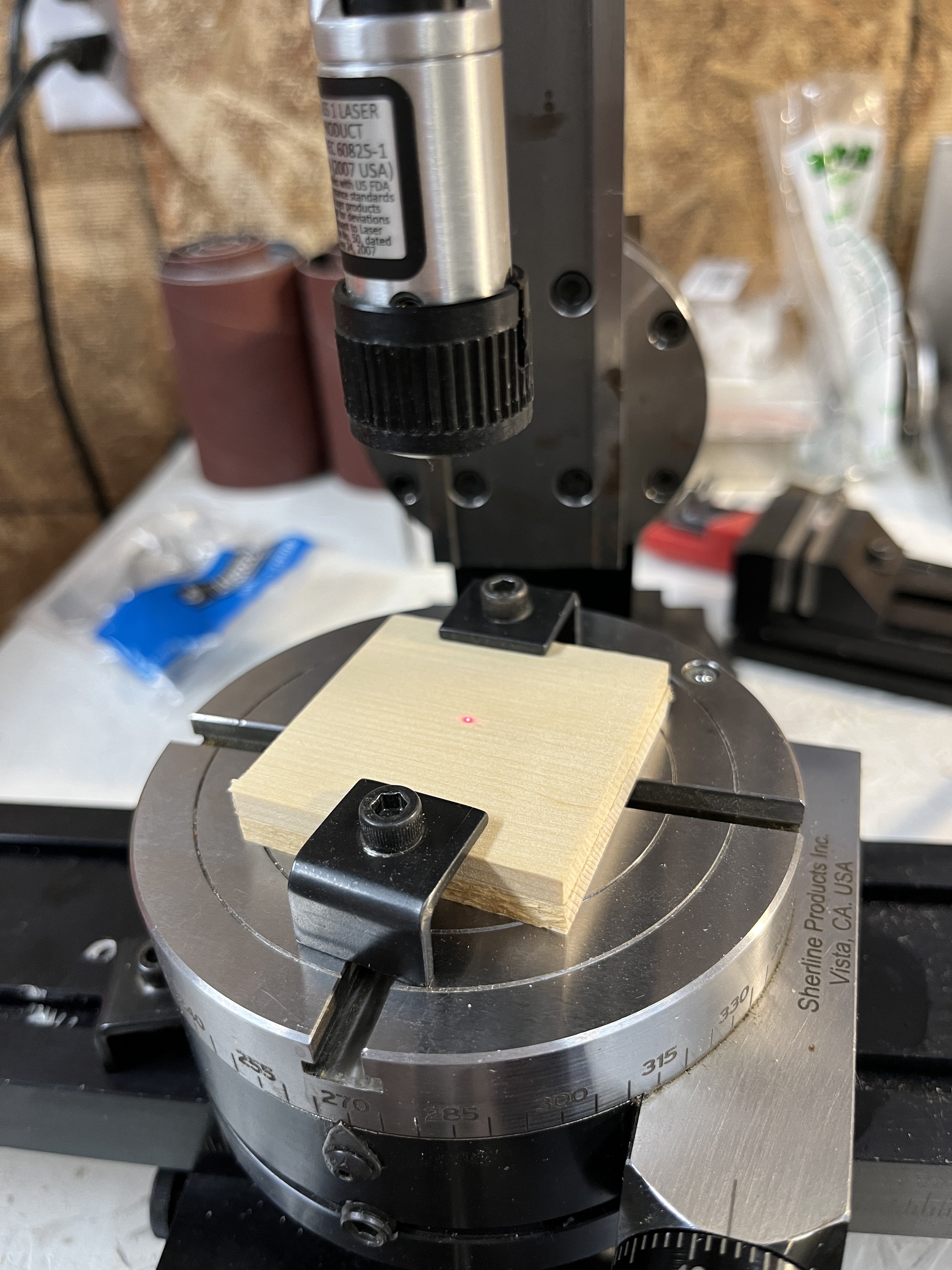
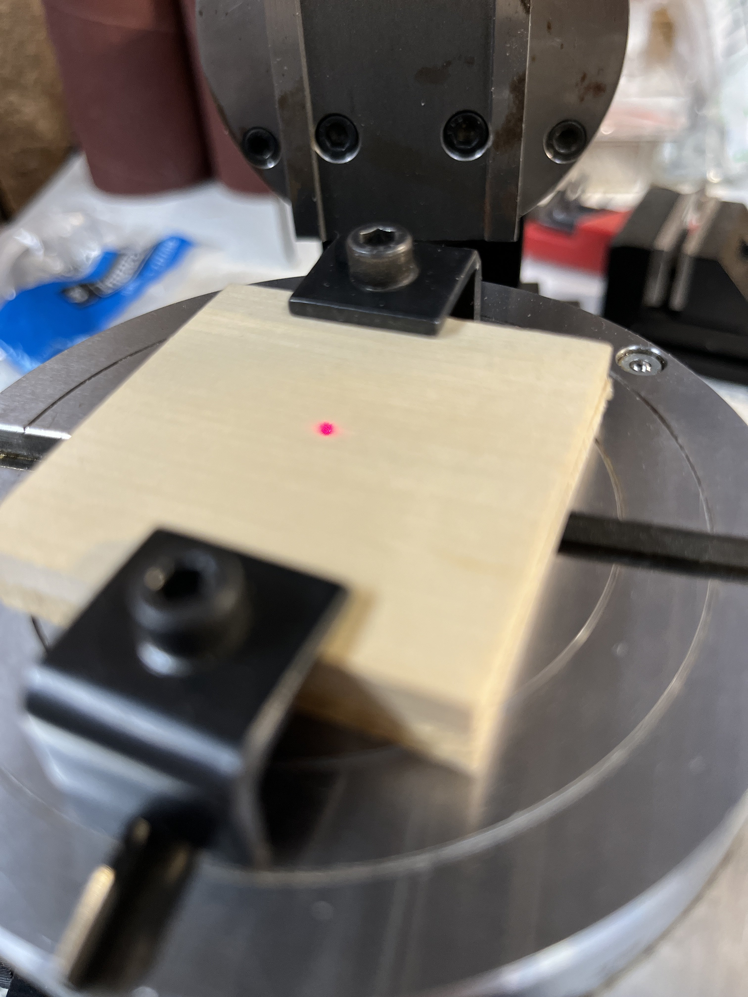
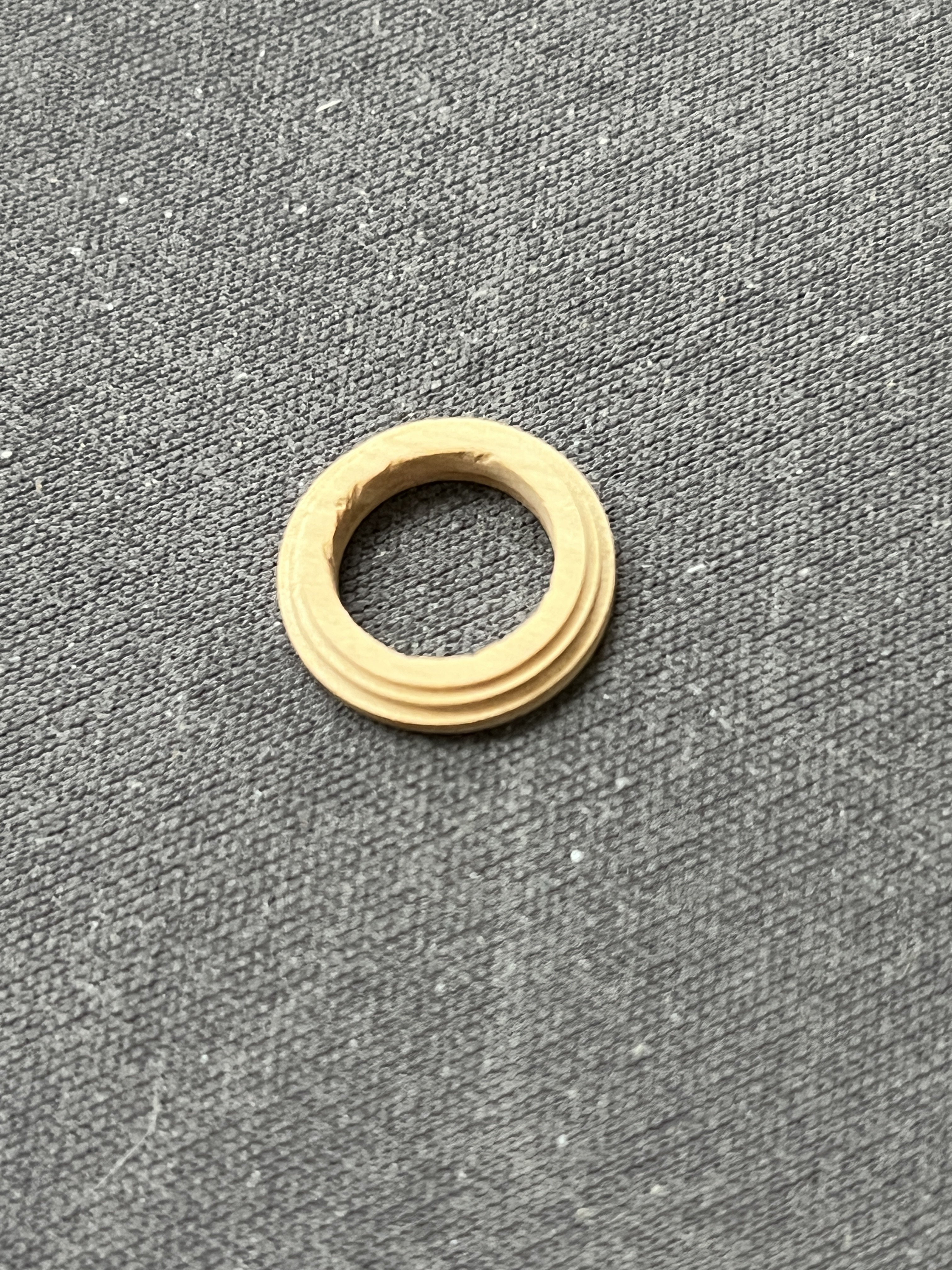
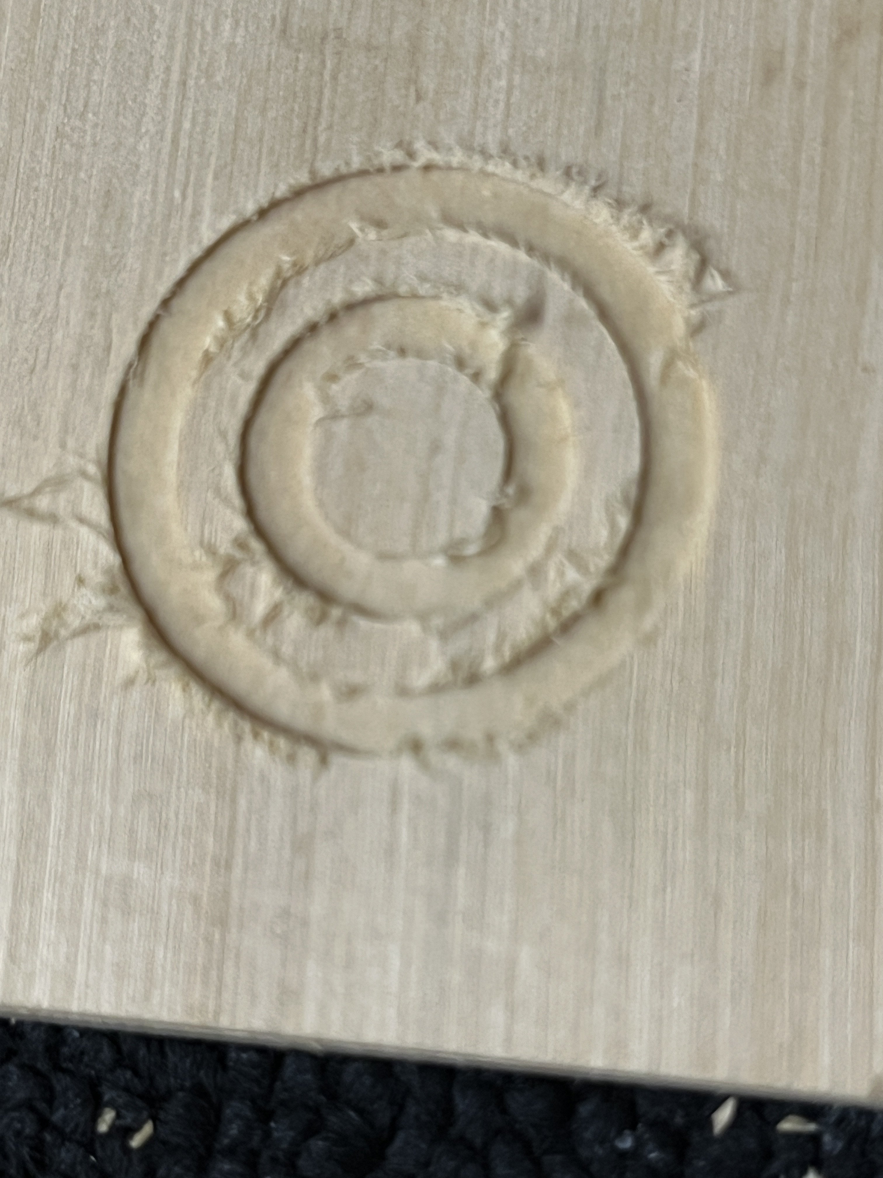
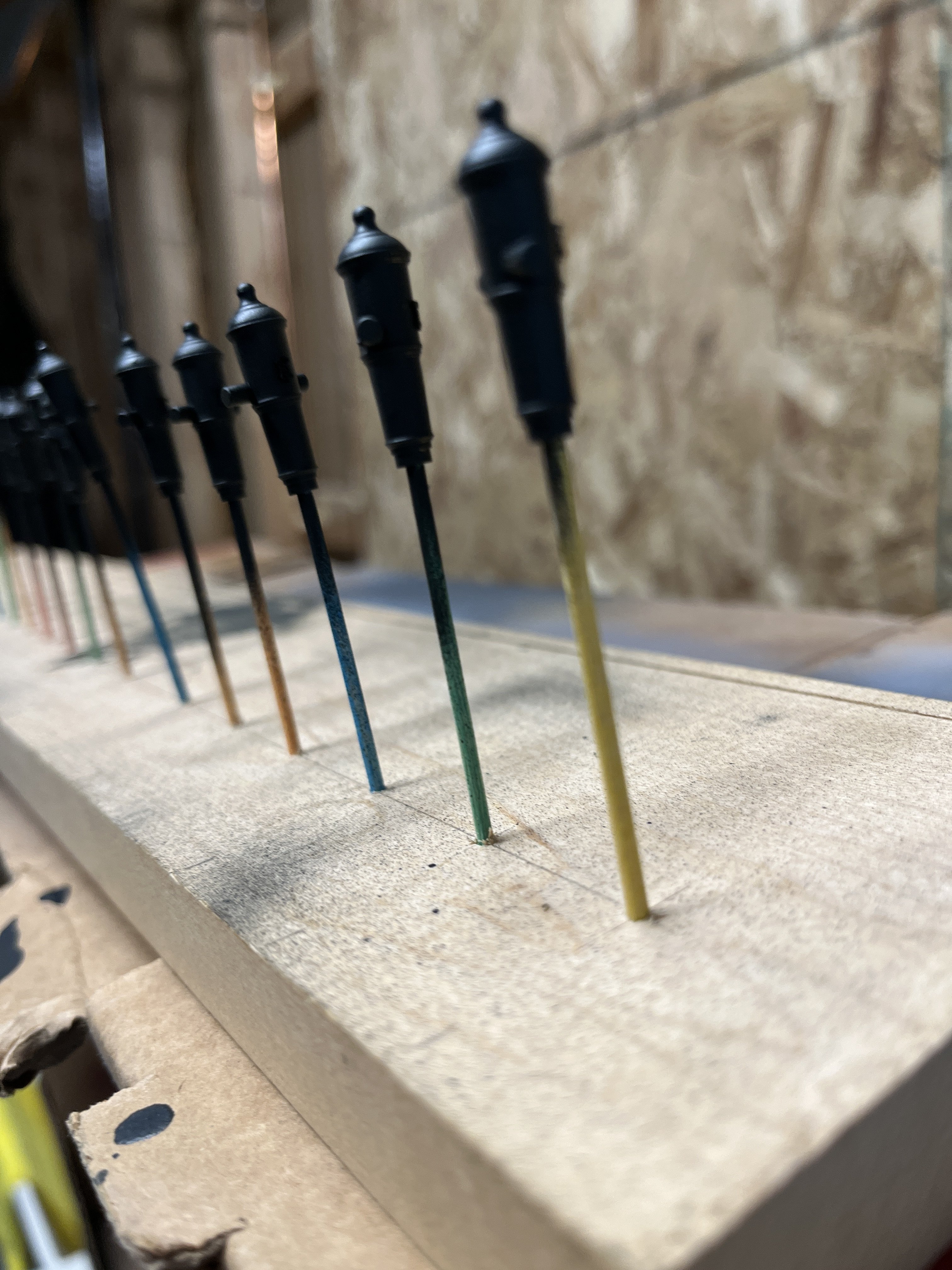
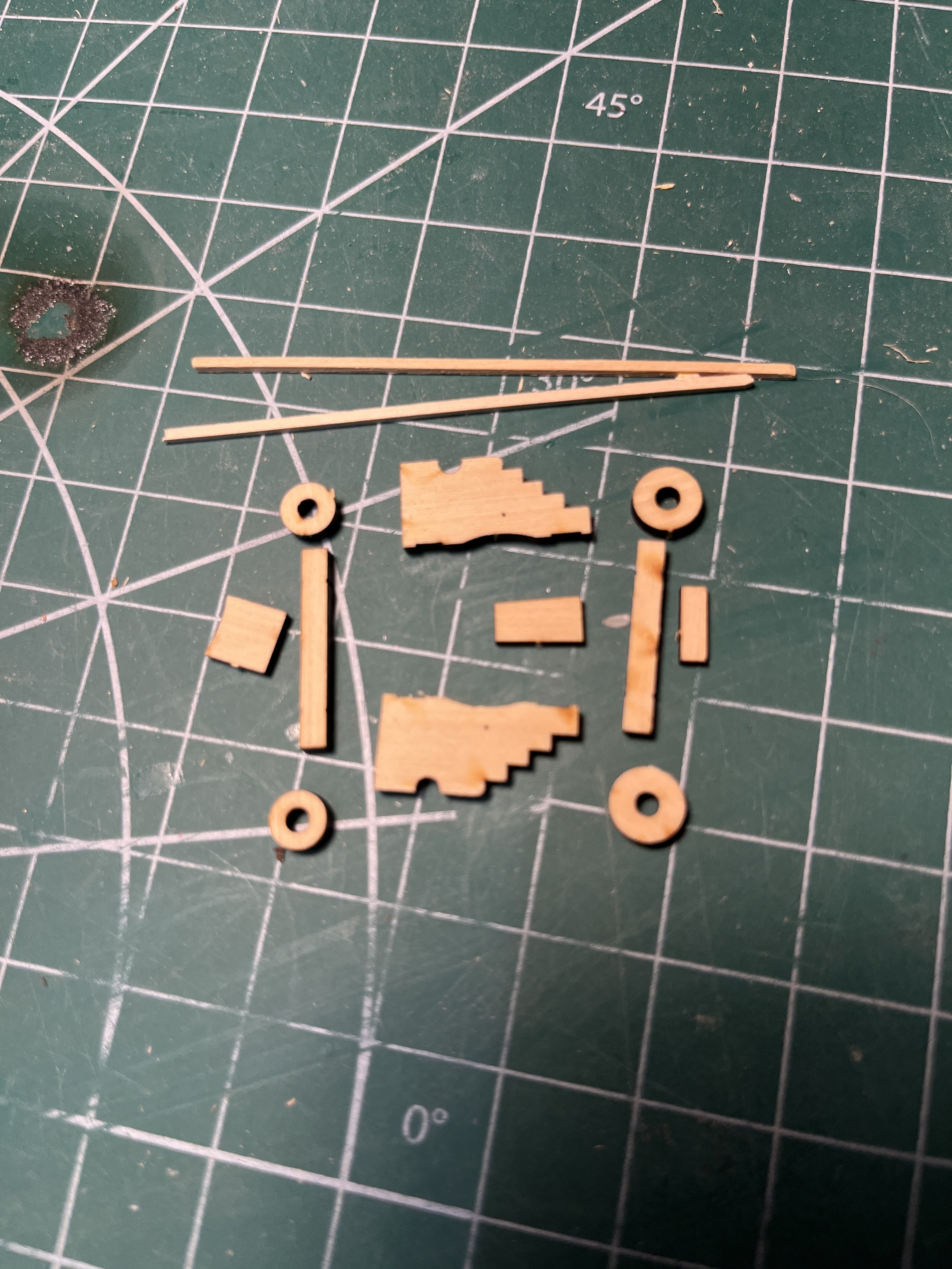
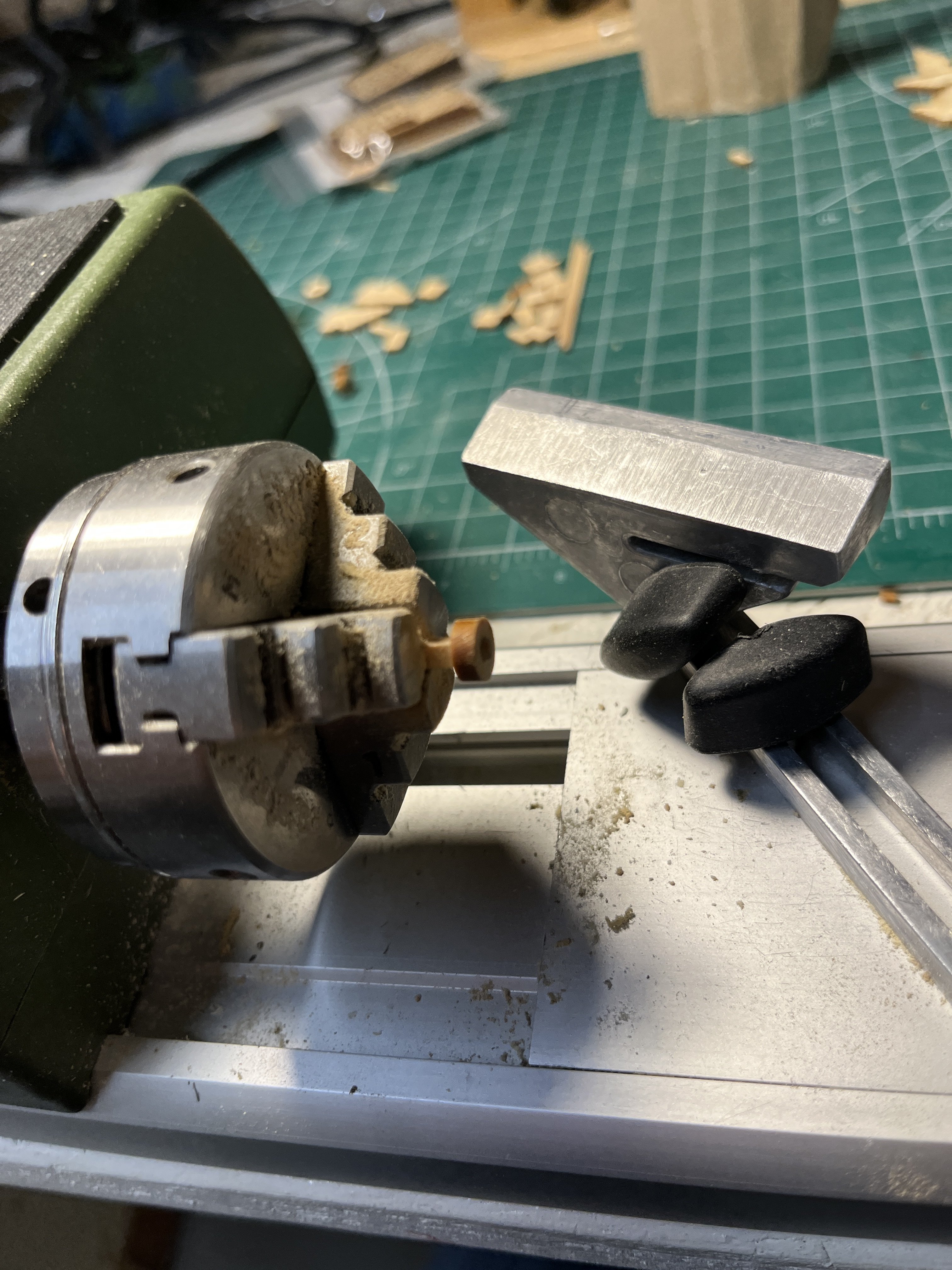
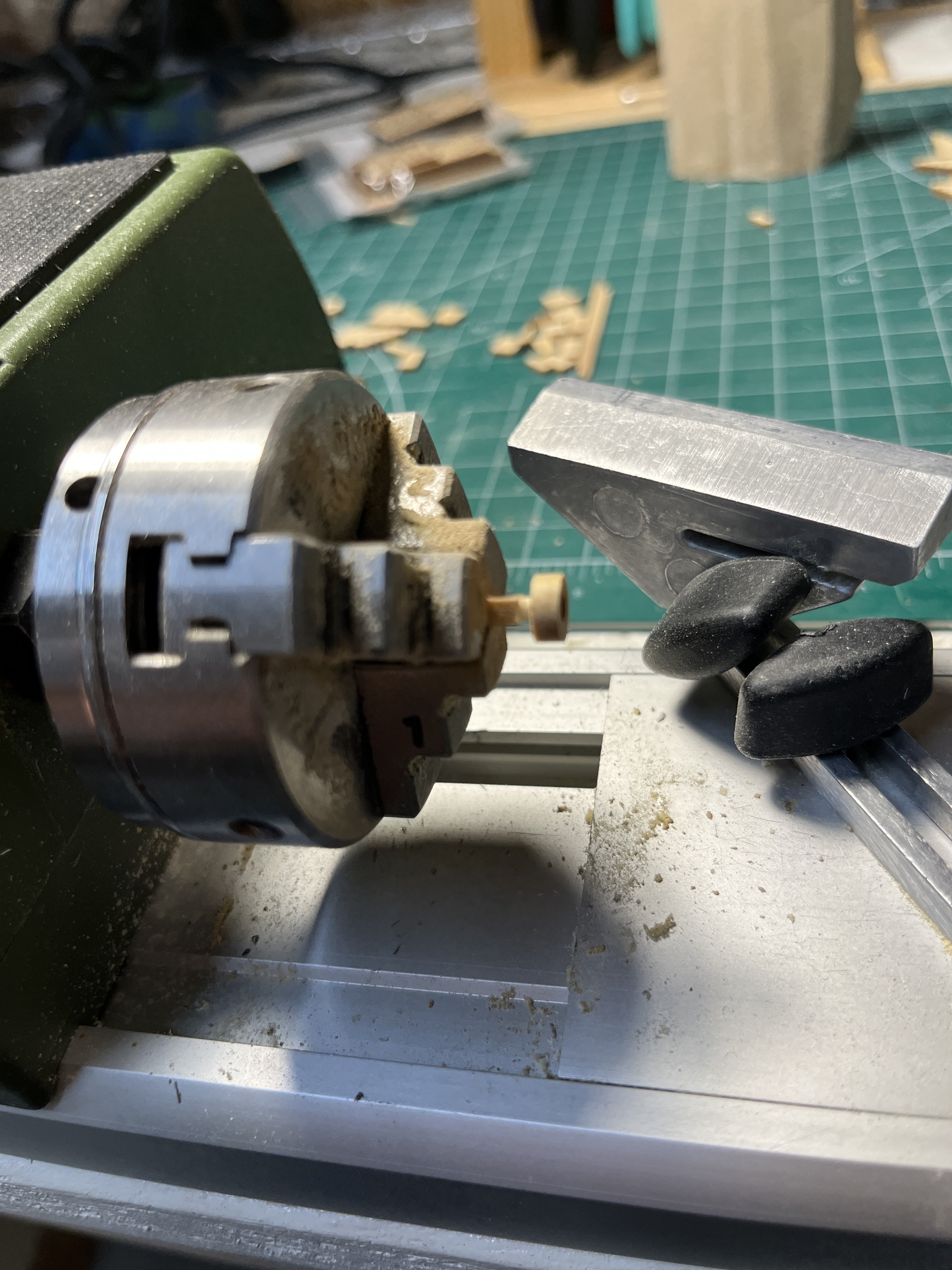
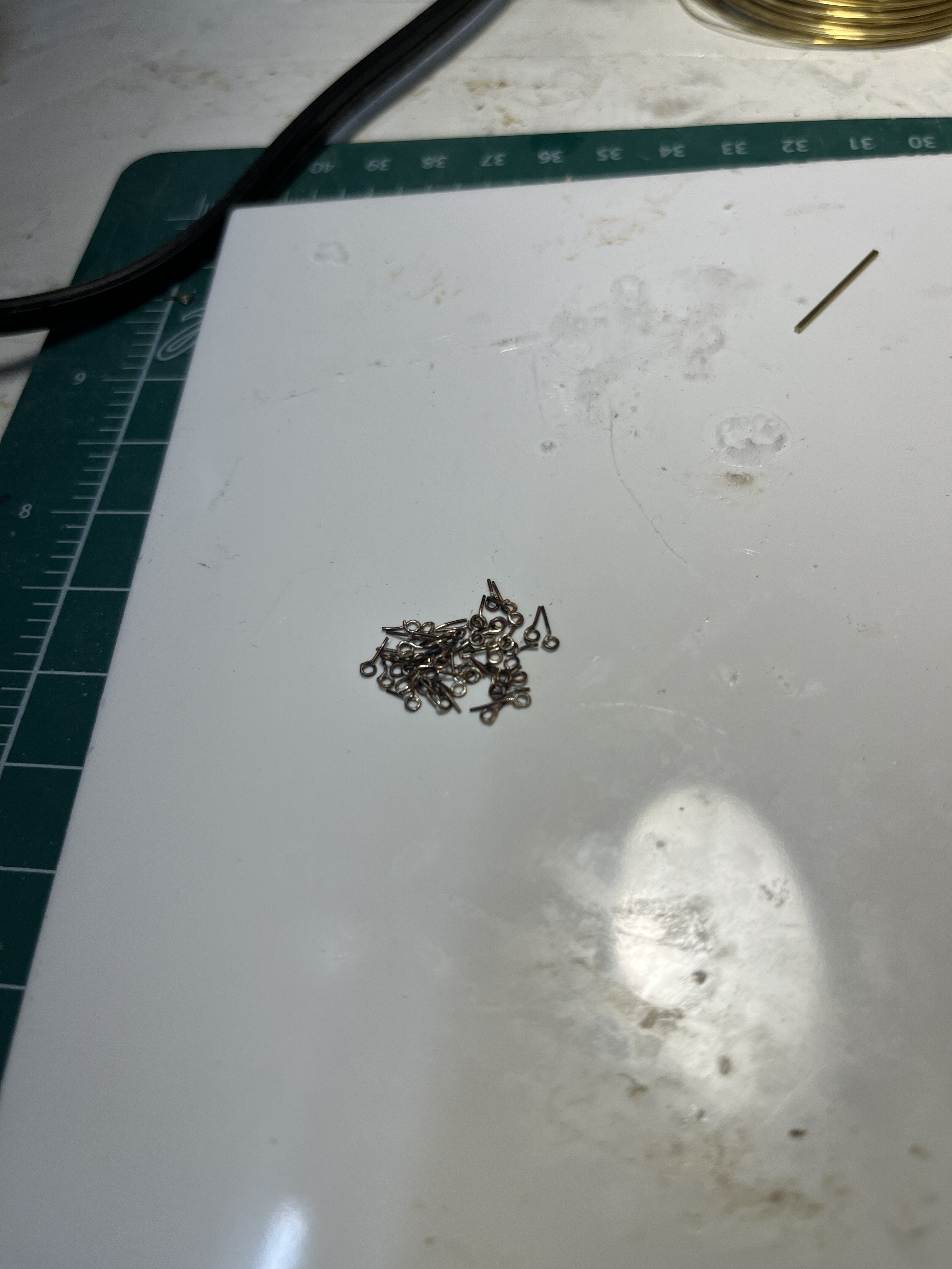
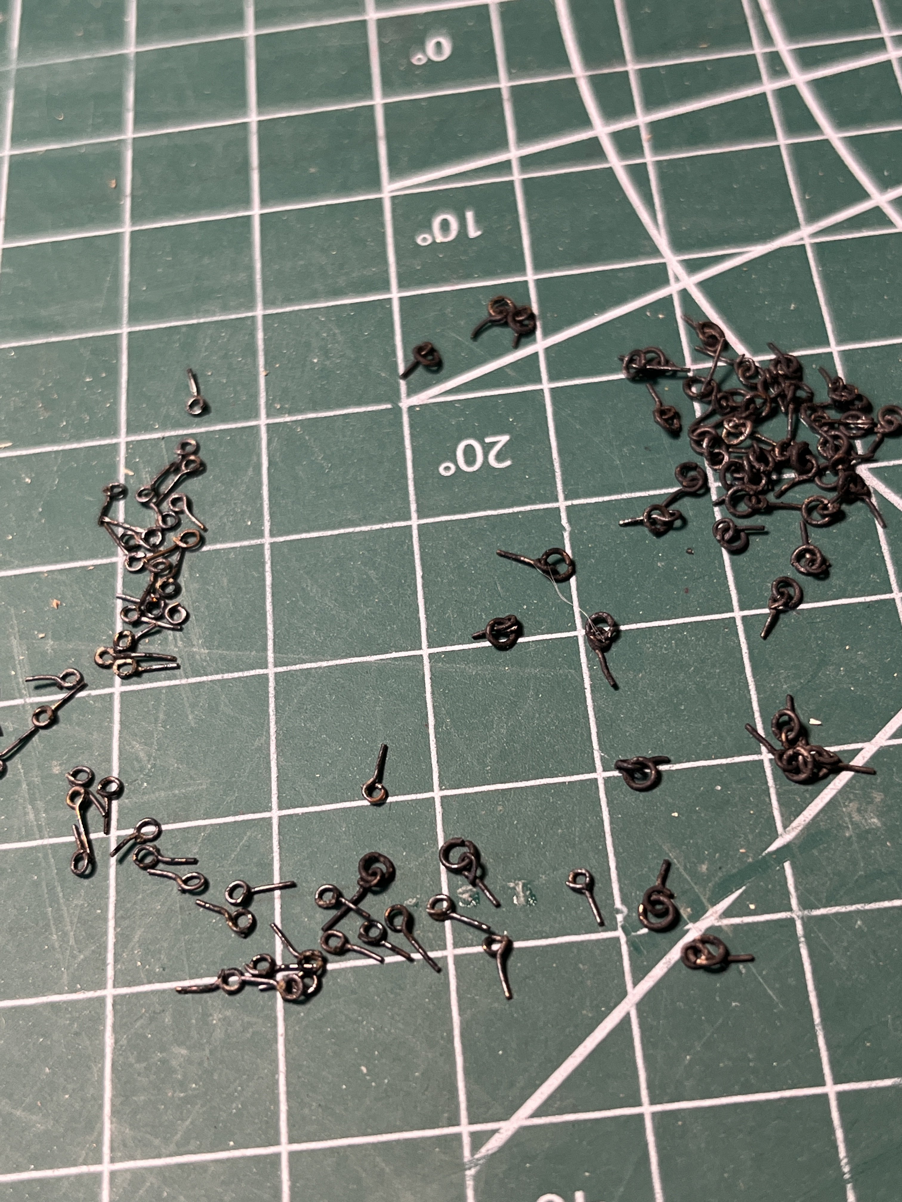
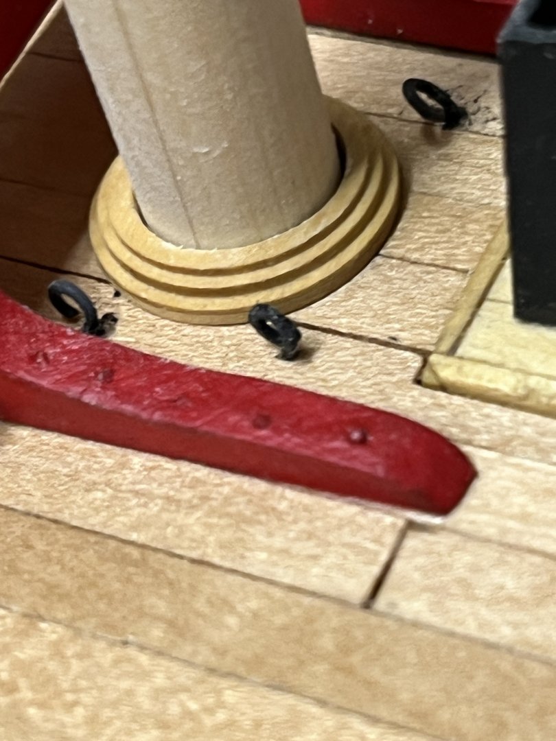
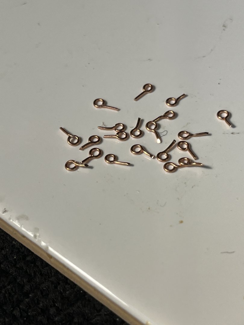
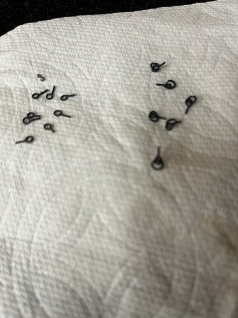
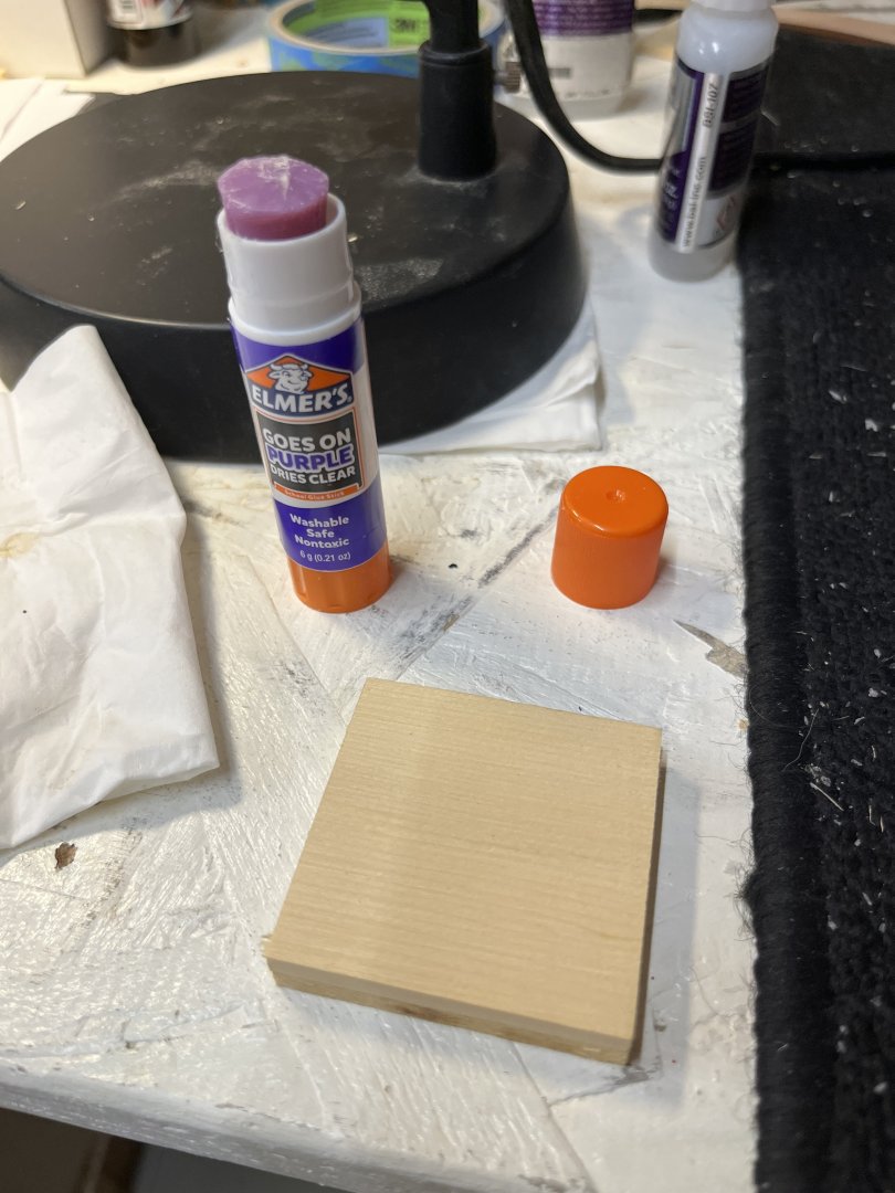
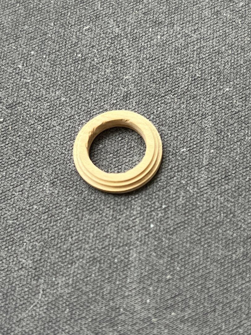
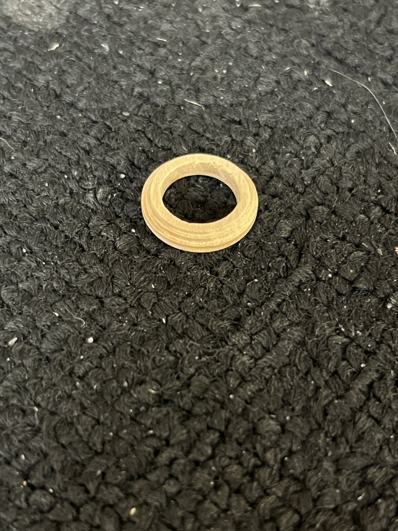
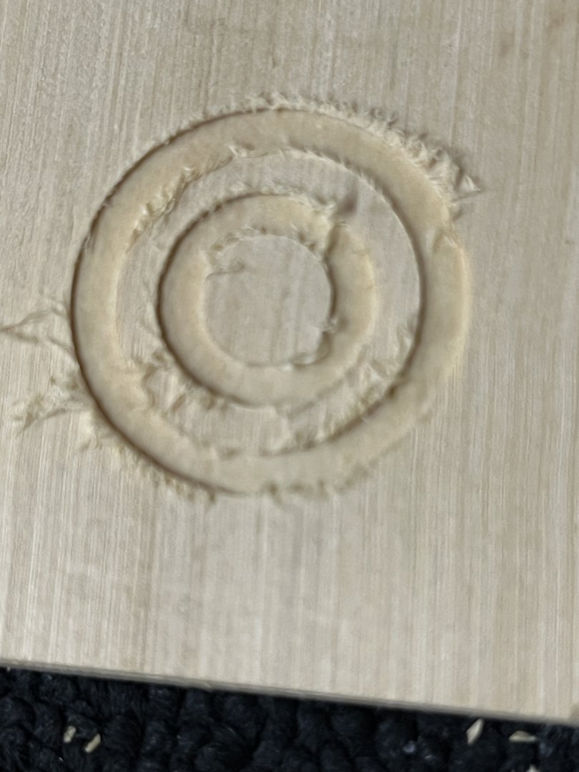
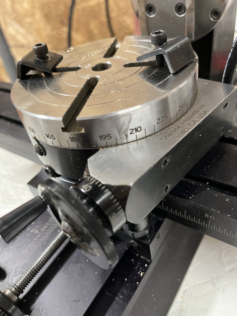
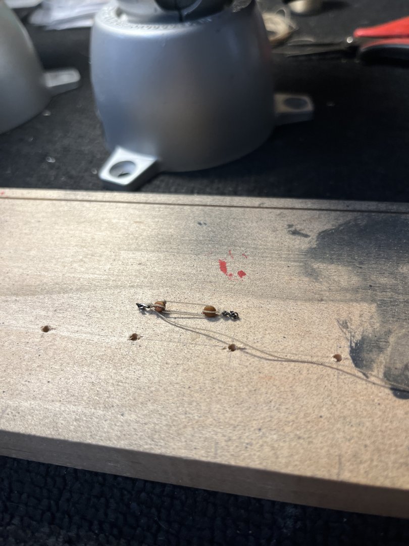
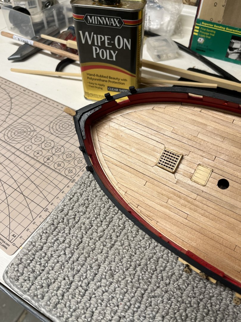
Good Morning on July 6 and it's been too long between working on the model and posts. I spent some time making the deck eyebolts using the same technique as before by silver soldering the rings closed. This afternoon will be spent plating the parts black and ready to put on deck. I had forgotten that in my notes the eyebolts had been etched and cleaned in the ultrasonic so that they were ready to plate. Sitting on towel to dry After looking at others methods to make the mast coat I decided to use my mill with the rotating table. My first attempt using Alaskan Blue Spruce was not successful as the softness of the wood just left fuzzy edges so out came boxwood. Using my rotating table mounted to the mill to cut the circles for the coat. I2mm boxwood wa used for the coat. The boxwood was not thick enough so I glued two pieces together with opposite grains for added strength. Using school glue as it makes a strong joint and can be easily remove with water. Mounted the wood was a simple process as you would on all mill beds. A 3mm end cutter was used to cut the circles. The hardest part was calculating the radii as 3mm is .118 so much drawing and calculating making sure I had the correct inside and outside diameter. Getting steps on the outside was simple after cutting down the depth and raise the cutter and with a smaller diameter. These are the finished mast coats, I made two for emergencies, prior to wipe on poly The little chips on the top will not be seen one I sand the mast coat to the correct height. Using my rotating table was a wonderful learning experience and I have many ideas of how to use the great tool in the future.


-
Martindale blades for Byrnes saw...
niwotwill replied to CPDDET's topic in Modeling tools and Workshop Equipment
Great information about how and where you got your bladed. With the two names listed I was unable to find how to contact them, could you explain how you were able to contact them? How many blades did you have to order? Thanks -
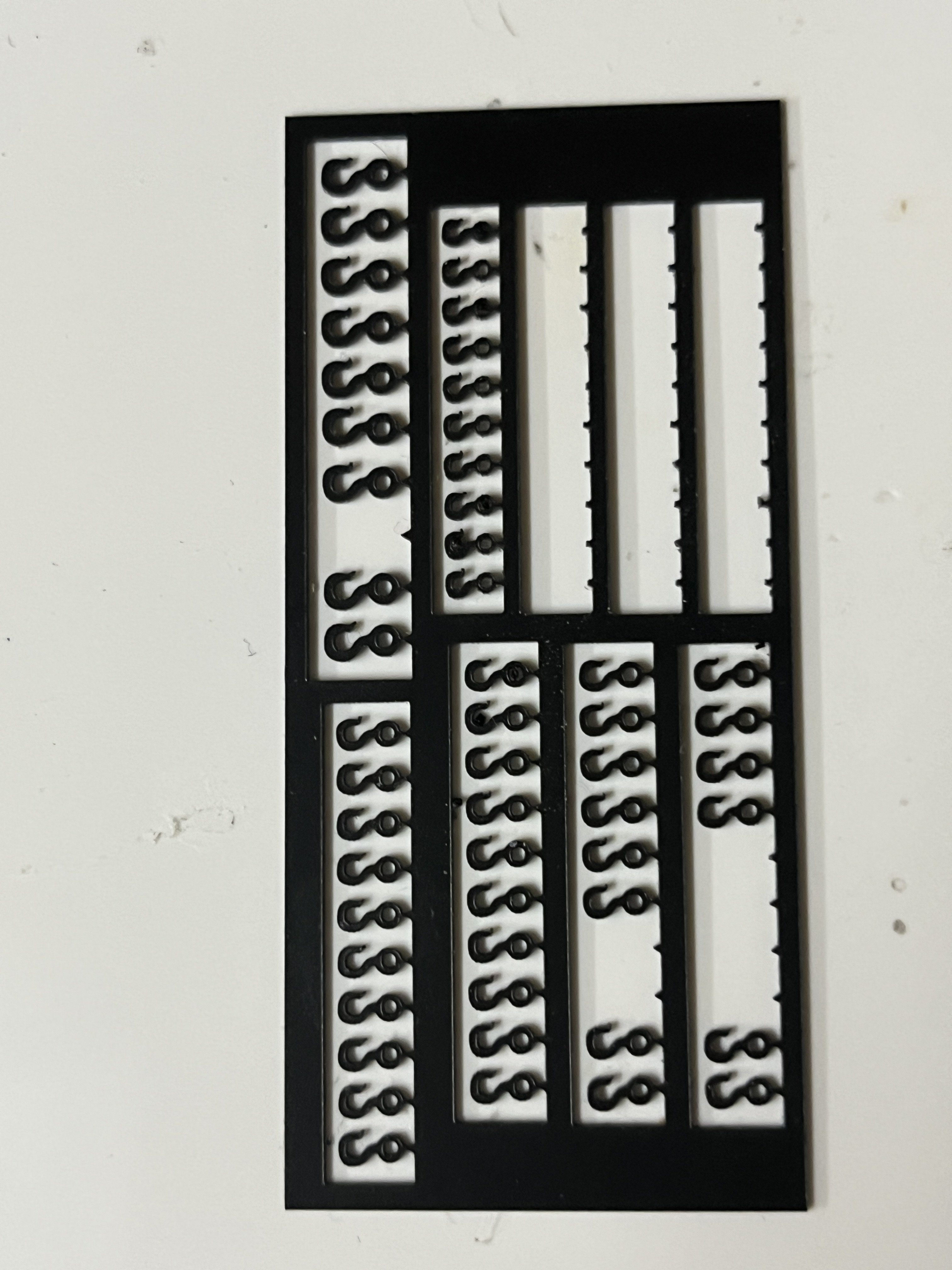
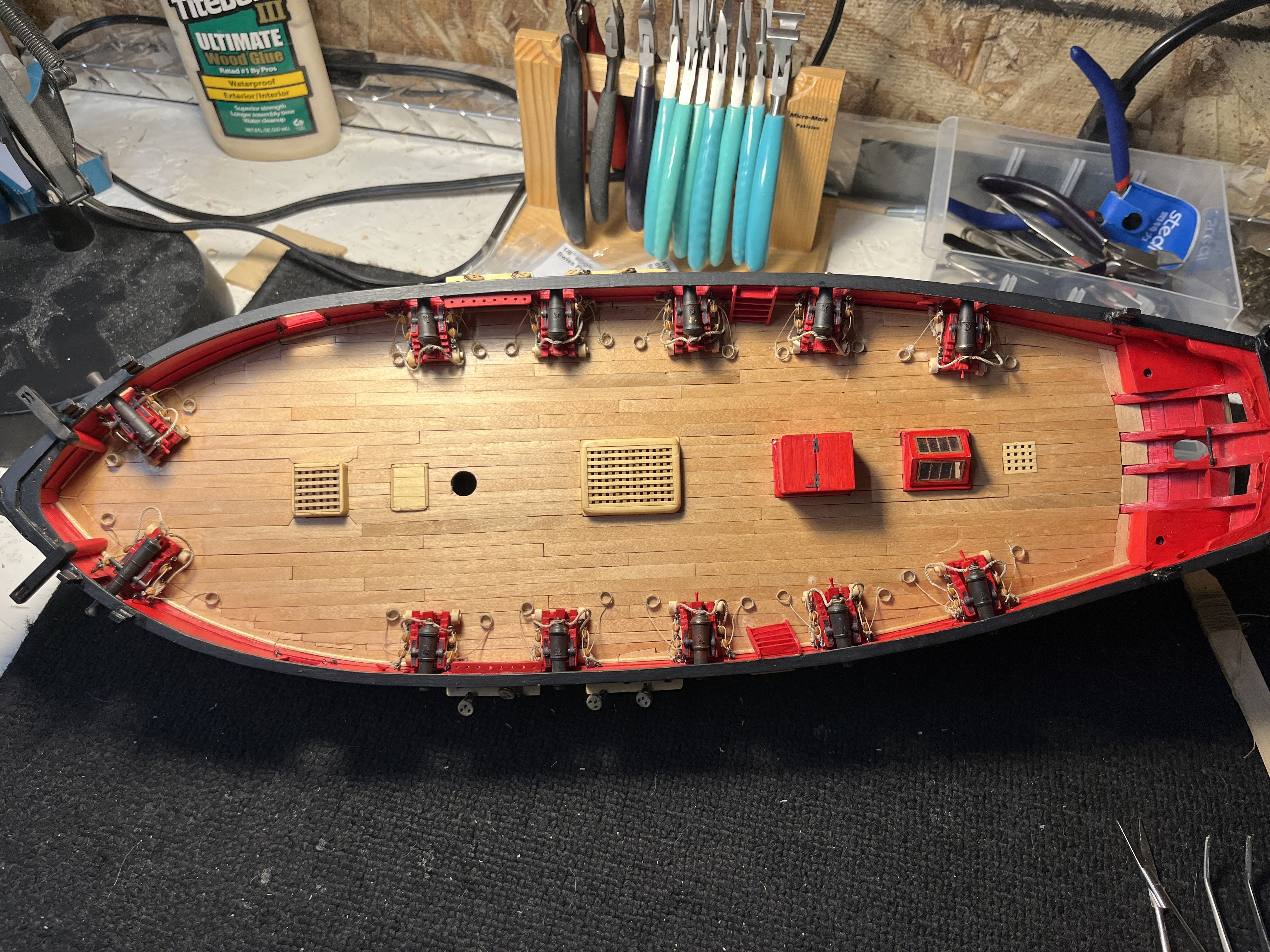
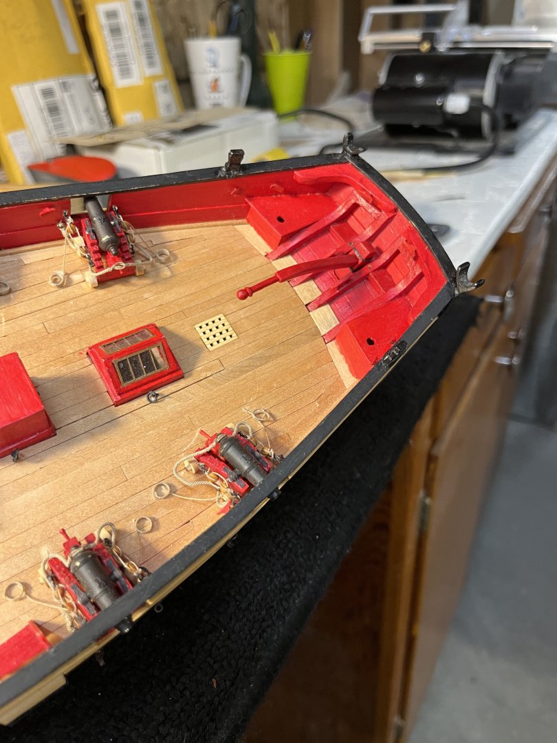
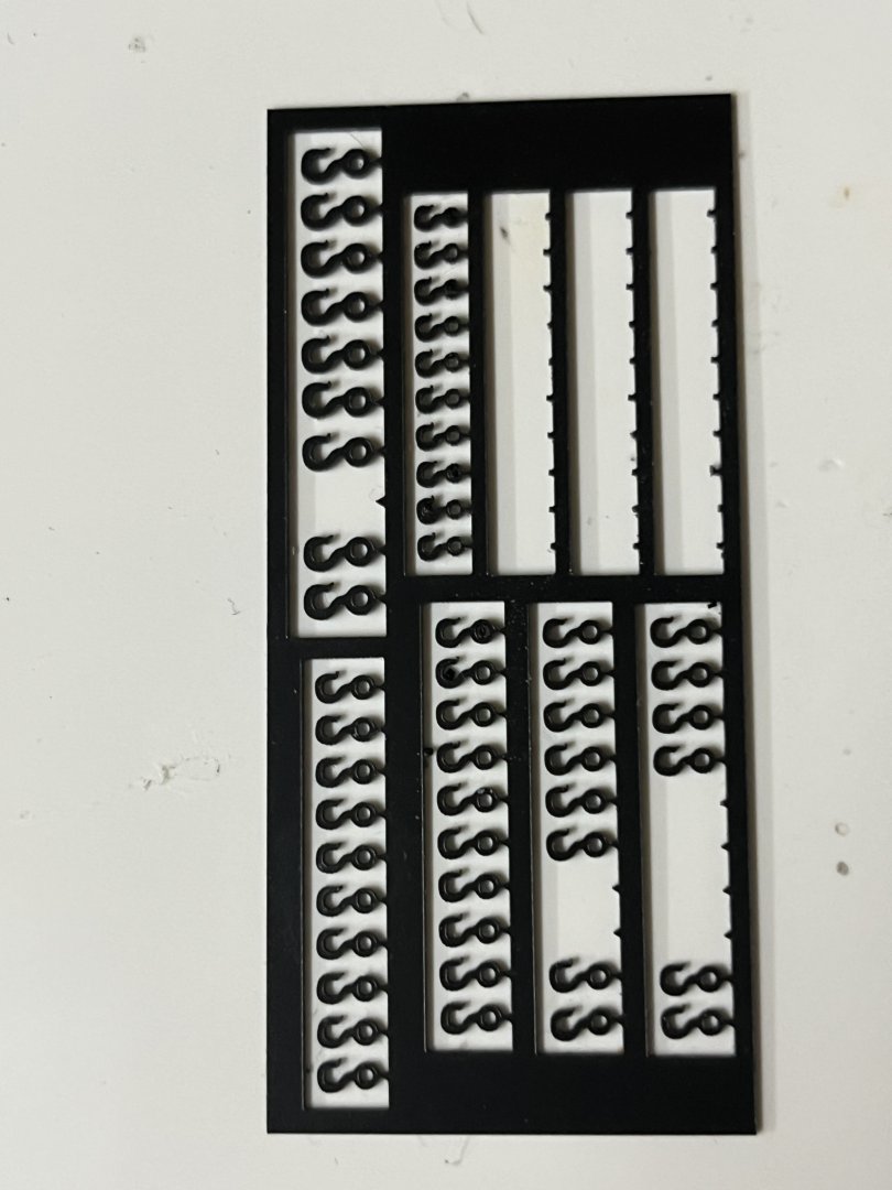
With the breech lines completed and the carriages glued to the deck it is now time to start the tackle. I used the 3d printed hooks from Syren Model Ship Company for the block hooks. The sheet of hooks had 3 sizes and I used the smallest which gave the visual proporations of hook to block. The 3d sheet gave the smallest hooks a visual thickness to the hook. A simple jig was made from a piece of wood that had been used for many purposes. The holes last used to paint the cannons with the jig and tackle visible the groove along the top was used to shape planks on plank on frame kits. The slot was quite unique to hold the plank while being planned to shape. This slot was make the thickness of the present blank. With the tackle made now it was time to rig the cannons. Again when a step seemed easy it proved not to be easy. Getting into the bulwark rings was very difficult requiring many sized and shape tweezers. The 3d hooks were fairly fragile and required the remake of several hook/blocks. Now with chapter 10 complete

-
Hello Glen
It's been awhile since I've checked in and need help. Mast coat is my next step and reading logs you mentioned @DelF as one to look at for help in you post #429 page 15. Could you forward the post where @DelF described his method?
Many thanks and your posts are amazing making great late night reading.
Willi
-
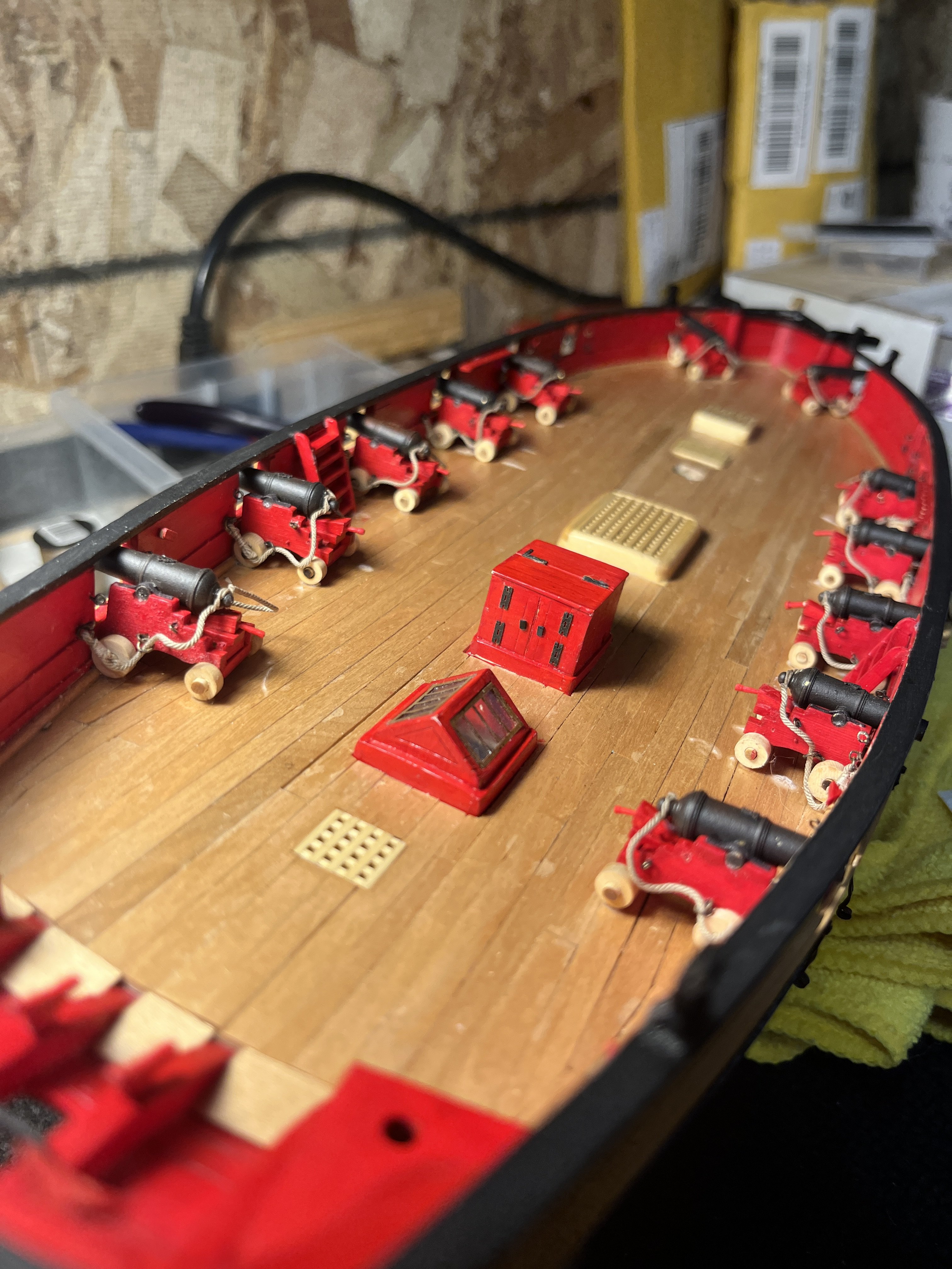
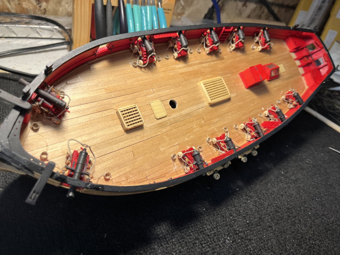
After much thought over the last few days I decided to leave the wheels in their natural color. I finally glued the carriages in positioGn on the deck and attached the breech lines to the bulwark. Getting the breech lines to hang/droop in a relaxed position is going to be a work in progress but they are starting. The next thing is to strop the blocks for the gun tackles.

-
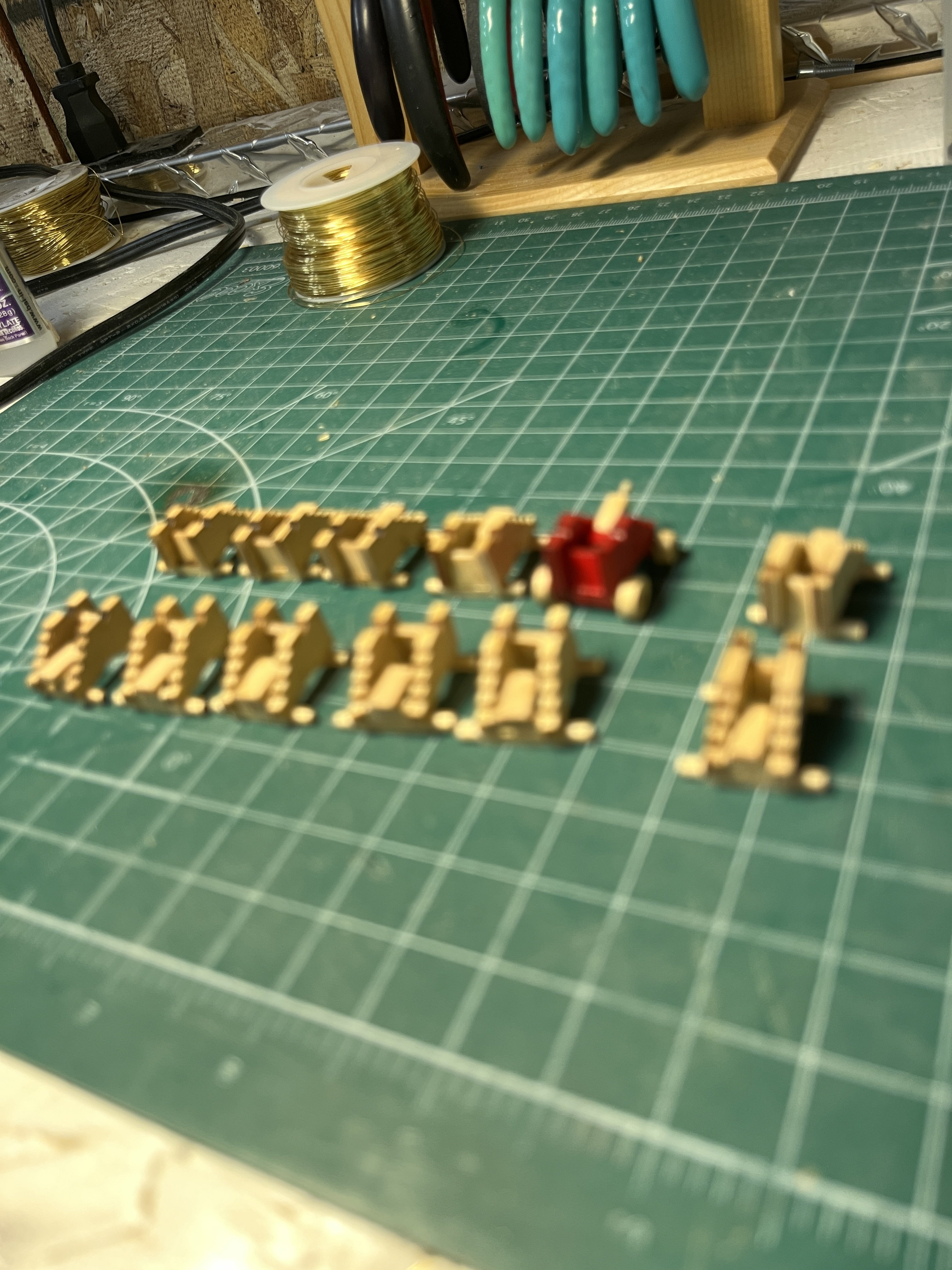
Had a slow period over the holidays and not much to show. I made the elm pumps and all the carriages along with the breech lines. carriages assembled ready for paint carriages and gun barrels painted elm pumps completed and I use 1/16" brass tubing for the discharge tubes leaving an exit hole although nobody will see the hole but I know its there. got the breech lines attached to the carriages and just placed the armanent for my pleasure I still have to make the attachment caps to sit atop the carriages. Also need to decide if the wheels should be painted and I might try staining a scrap piece of AYC a medium dark to dim the wheel brirness. Tomorrow I'll start the harnesses and glue the guns in place.


-
Good thing they're not glued. Thanks for the observation
-
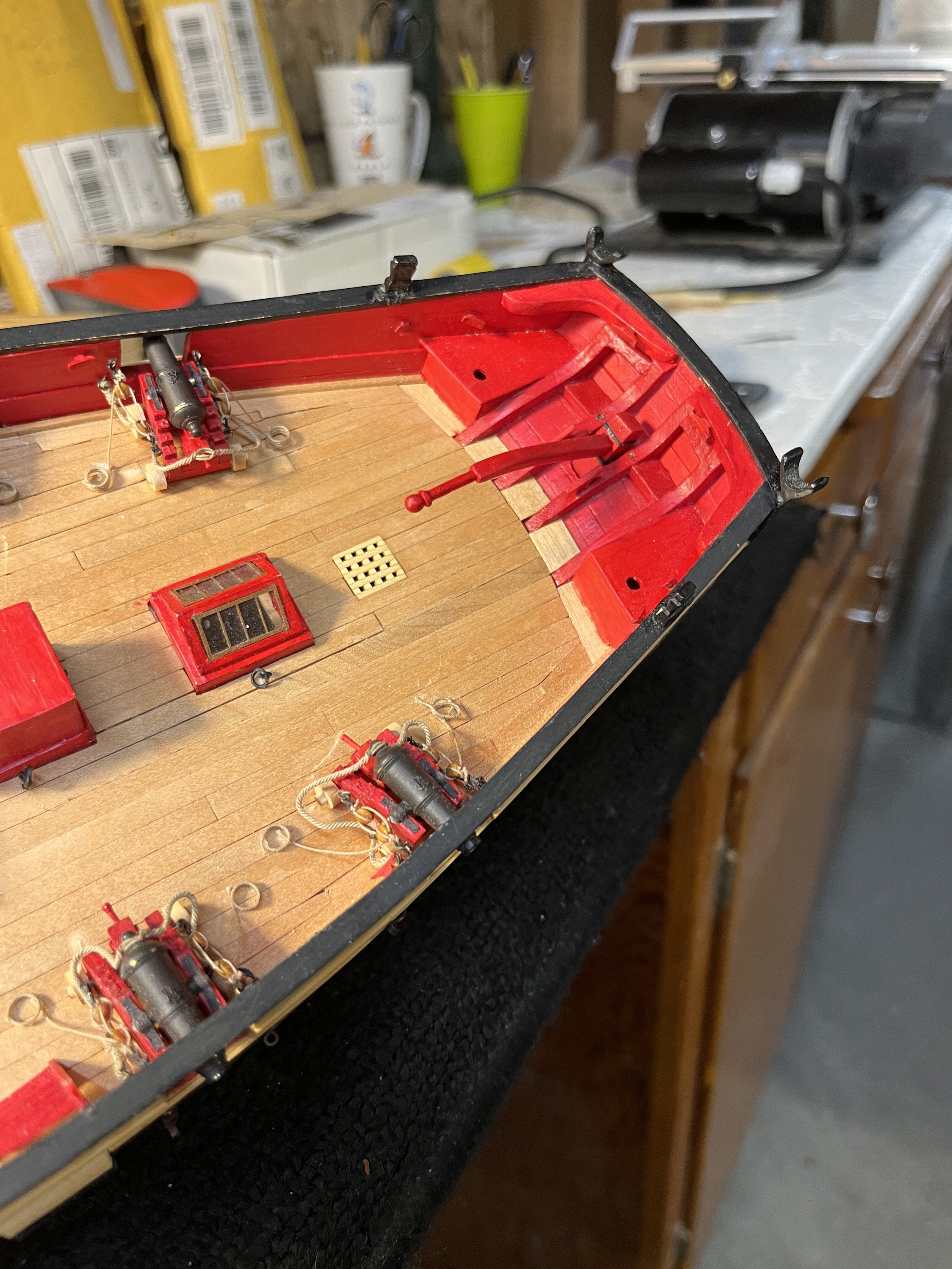
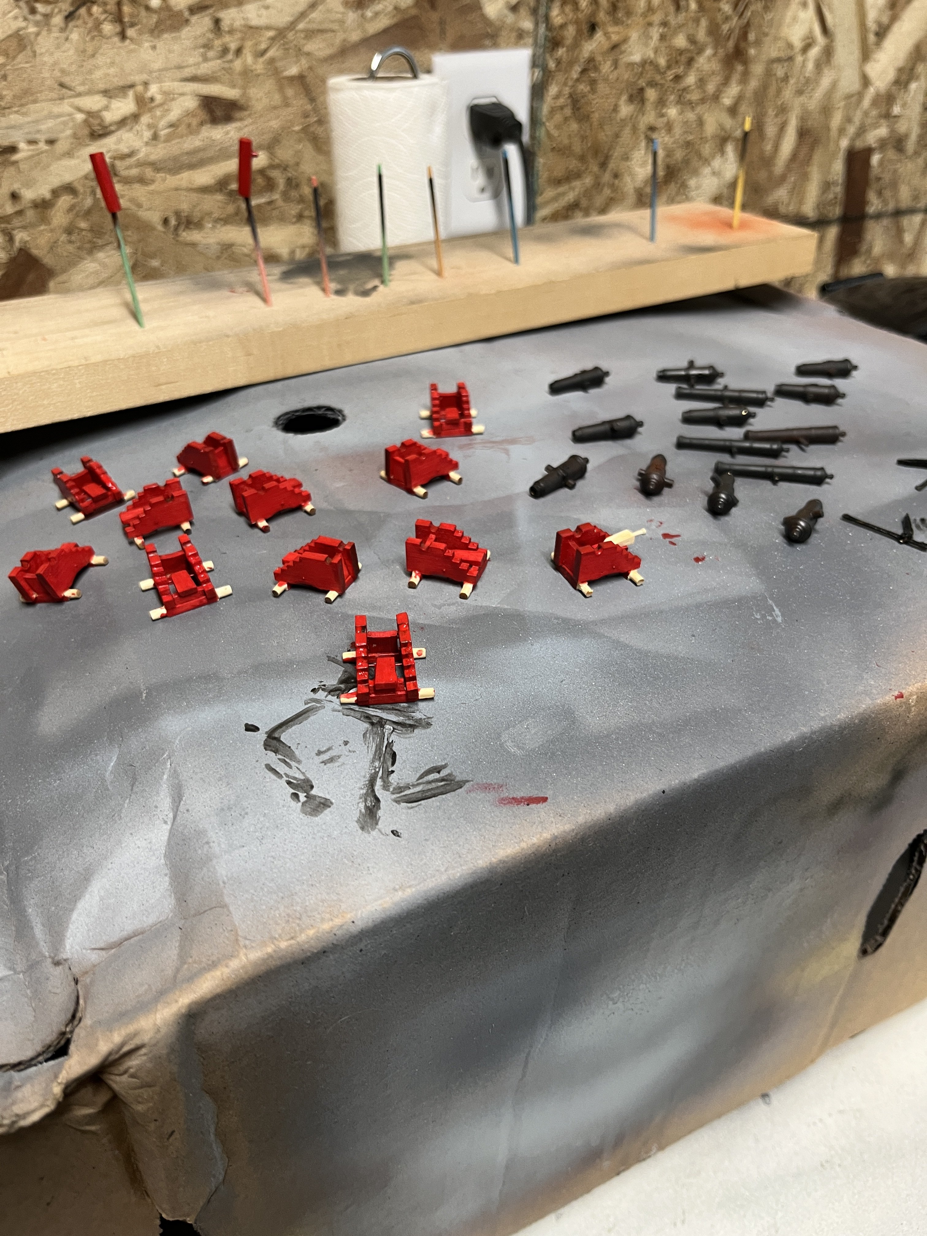
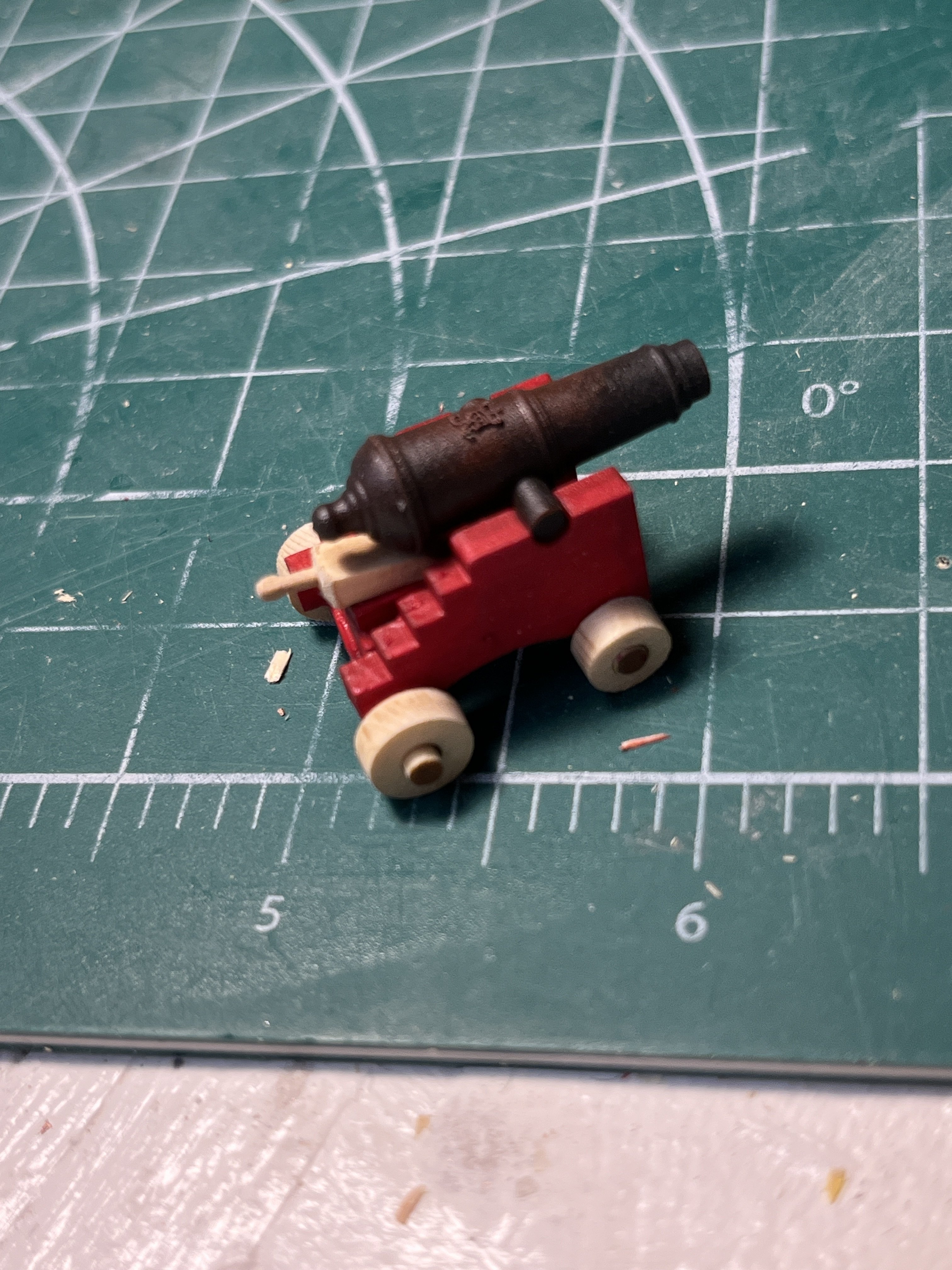
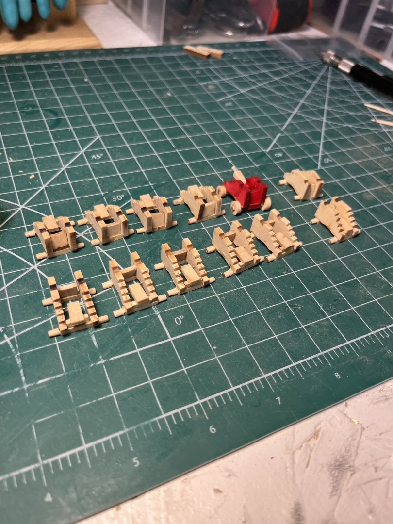
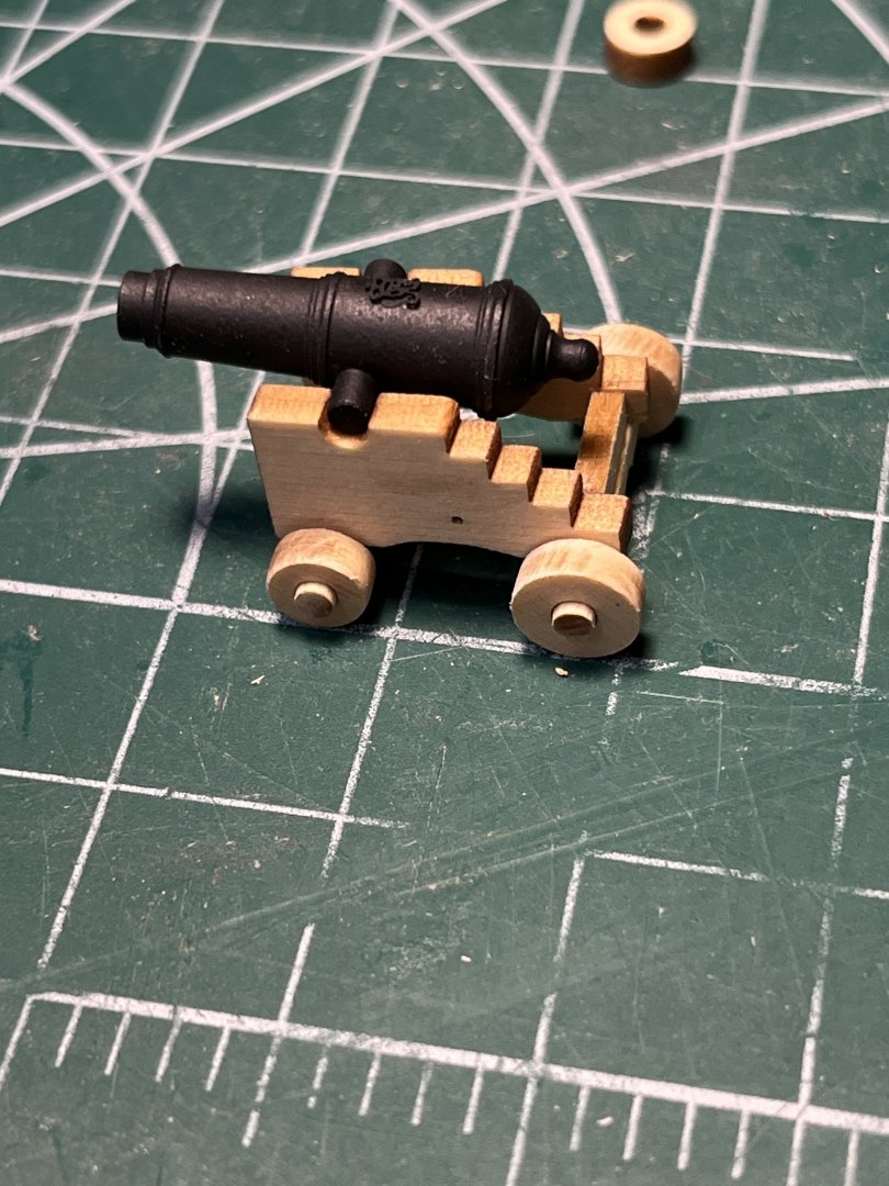
I completed with the cannon painting and weathering with only a minor mishap. I don't remember if I stated that I'm using Syren Models brass cannons and carriage kits. The first step was to clean the brass cannons by soaking them in lacquer thinner. Next washing them in warm soapy water followed by a thorough rinse and a drip dry. I sprayed them with a coat of Mr Eds surface 500 for a primer followed by Tamiya Nato black. I hadn't glued the pins as I think the paint will hold sufficiently until resting in the carriage. Using a weather powder of rusty brown and dusting until I liked the surface. When complete a light coat of Tamiya flat clear was added to protect the weathering. And the final result is The carriages were a small model in their own and below are the parts of each. I want to thank Chuck and Syren Models for the spare parts of each kit. With the axles requiring shaping for the wheels I figured this would be my starting point. There is laser mark detailing how far the axel needed to be rounded. I used my lathe with the axle chucked and a flat swiss file was used for rounding by lightly using the file. Removing the laser char from the wheels was accomplished during the rounding of the axle. Sliding the wheel onto the axle while an interference fit existed. Spinning the wheel and using the flat file made the job very easy. before removing the char after removing the char Assembling the carriages required making a jig similar to the one shown in the monograph. The assembly required a mental process. With long axle rear and large wheels on short axle so easy to mess up. I made one carriage as a prototype making sure I hadn't done something wrong. Assembly glued and ready for paint. I decided to leave the wheels natural so the axle end needed to be masked is sprayed so I had painted the prototype. Painting proved to be easy enough. The ends of the cedar pieces are an open pour so paint soaked in leaving uneven dark colors. Many coats of paint were required. Basic carriage assembly First almost complete. I like the wheels and quoin left natural but the axles have darker ends that I'll live with.


-
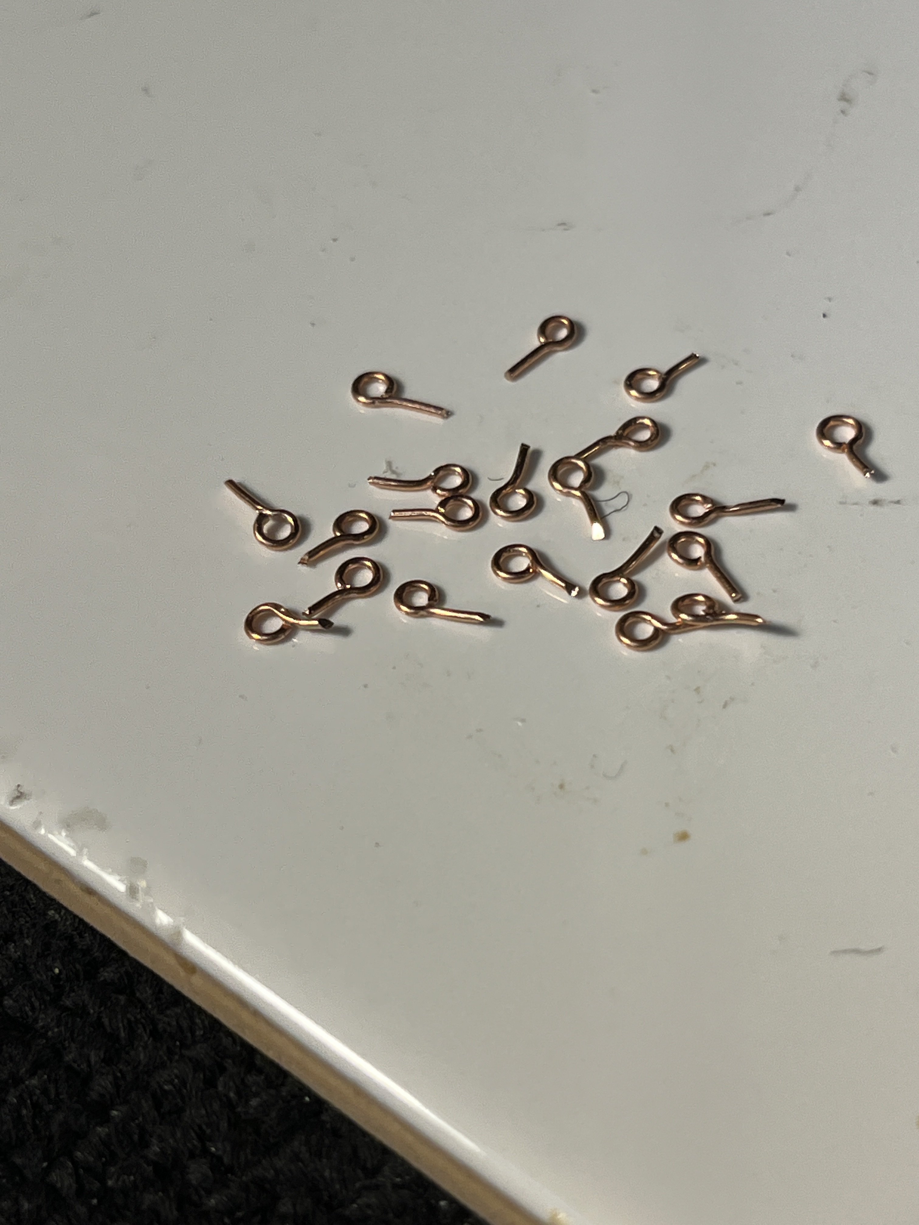
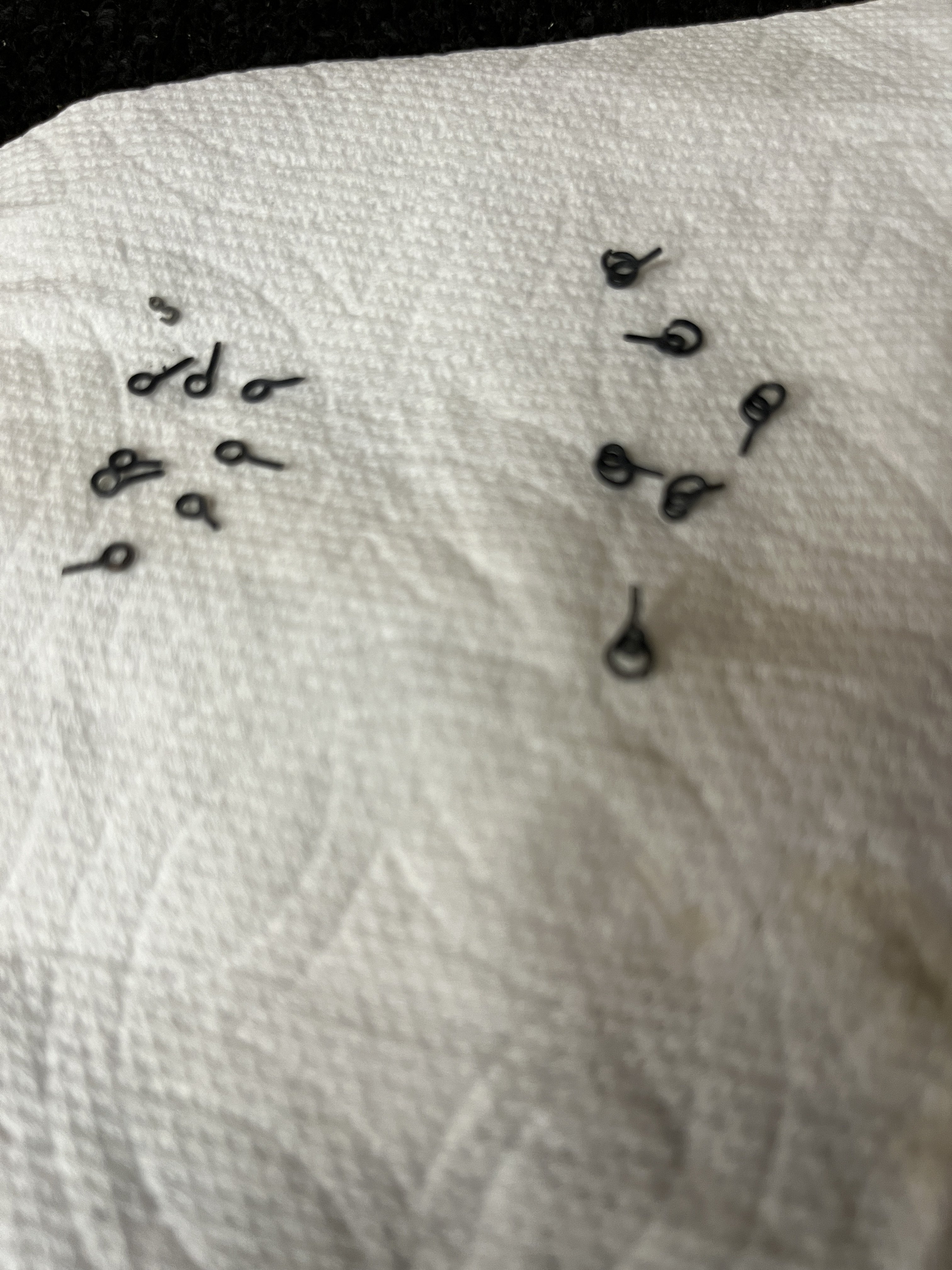
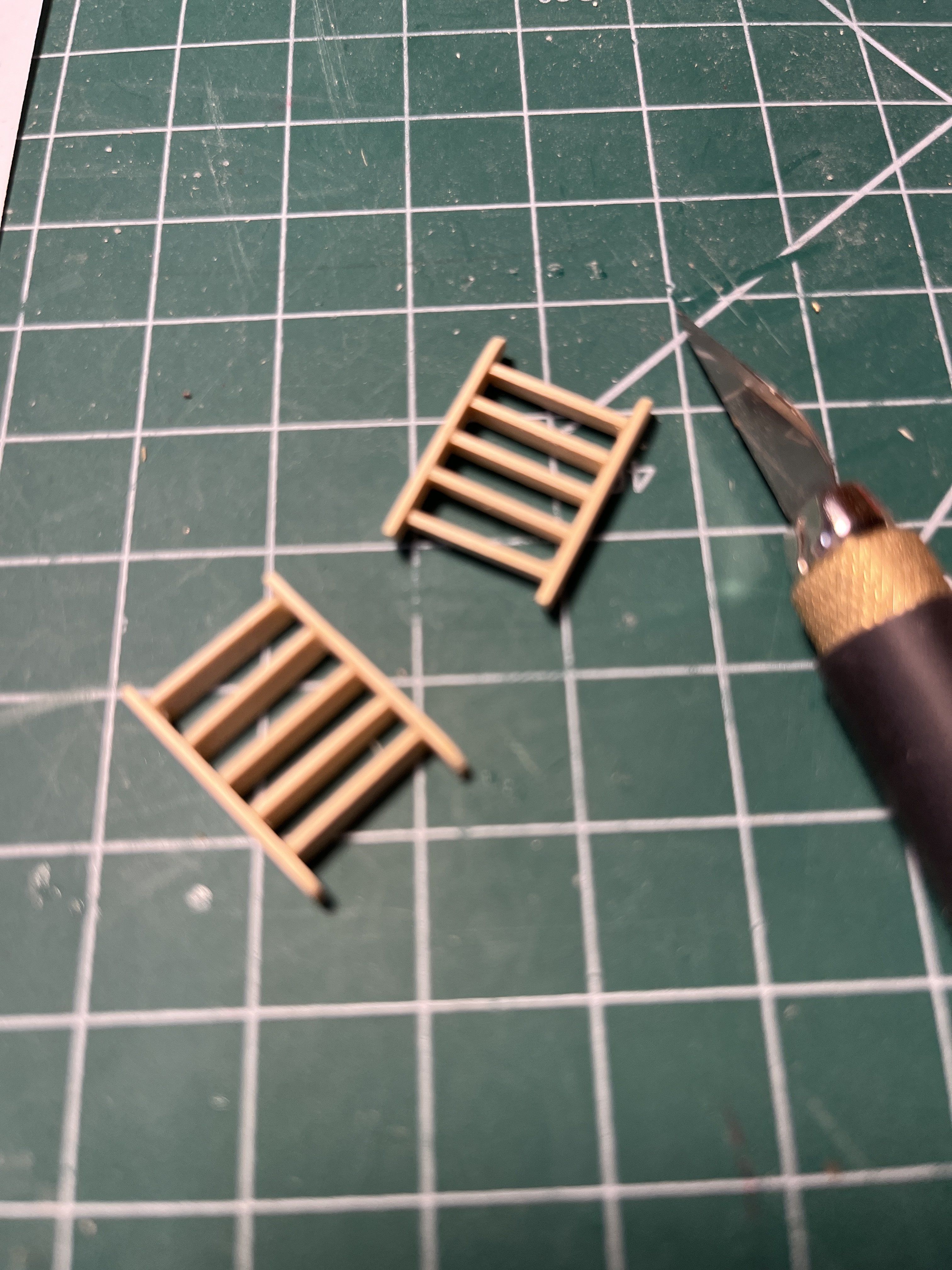
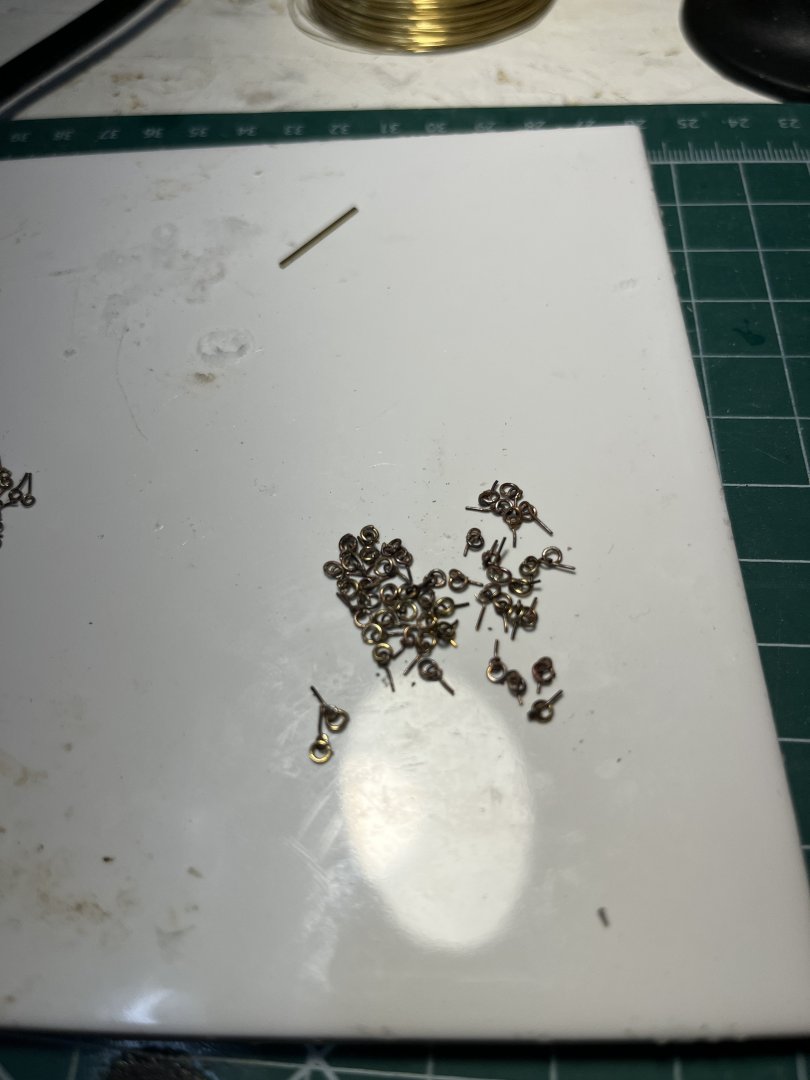
Well it's been several months since my last post and I'll bring the log up to date. Lost some energy to work on Cheerful due to my daughter's wedding but not back and working in full steam. I started with chapter 10 by maaking 100 eyebolts for the bulwark and gun carriages. My method is fairly simple by twisting a length of 26 AWG wire around a twist drill of a size to create the inside diameter. Then the loop is soldered to the stem with the excess loop cut and filed smooth. The stem was bent perpendicular to the eye creating a post. These are the eyebolts prior to trimming and etching prior to blackening. Next was to make the loops for the large gun harness. Using a larger diameter twist drill and 24 AWG wire creating the larger hole with heavier ring. Take the open ring and inserting into the smaller eyebolt the ring was soldered to close. I used a hard silver for the eyebolt and a soft silver for the ring thereby not breaking the eyebolt solder joint. Again before etching and blackening. This was a mind bending process that took 3 days of tedious work and I am very glad its over. The ladders were next on the list of things todo. Getting back to wood work was like a holiday and the ladders were fairly simple to make. With the ladders painted I glued the in place on the bulwarks. Pinrails were the next thing on the list. I thought the bow pinrail would be the hardest but the side rails were more difficult due to the slight radius of the bulkhead and the rail having a parallel side. The catheads were the last of the inboard detail prior to cannon carriages. I used the same procedure as the monograph described in making the catheads with two prices. The first step was to notch the cap rail which was very nerve wracking to say the least but after much carful cutting and sanding to notch was completed with no mishaps. The inboard piece was the most difficult trying to get it to sit flush with inboard bulkhead planks. Got this done with several pieces and much cutting and sanding when the fit was correct the length was made flush with the bulkhead top. The top piece was very straight forward using the method of drilling four holes and notching between them simulating pulleys. Taking the pieces laying them flat on a glass tile while glueing together maintain the flat joint. Once the glue set the catheads were sanded in preparation for painting. The vertical piece was painted red prior to installing and the black was applied after the installation. Fitted prior to paint Finished catheads Now onto cannons and rigging.


-
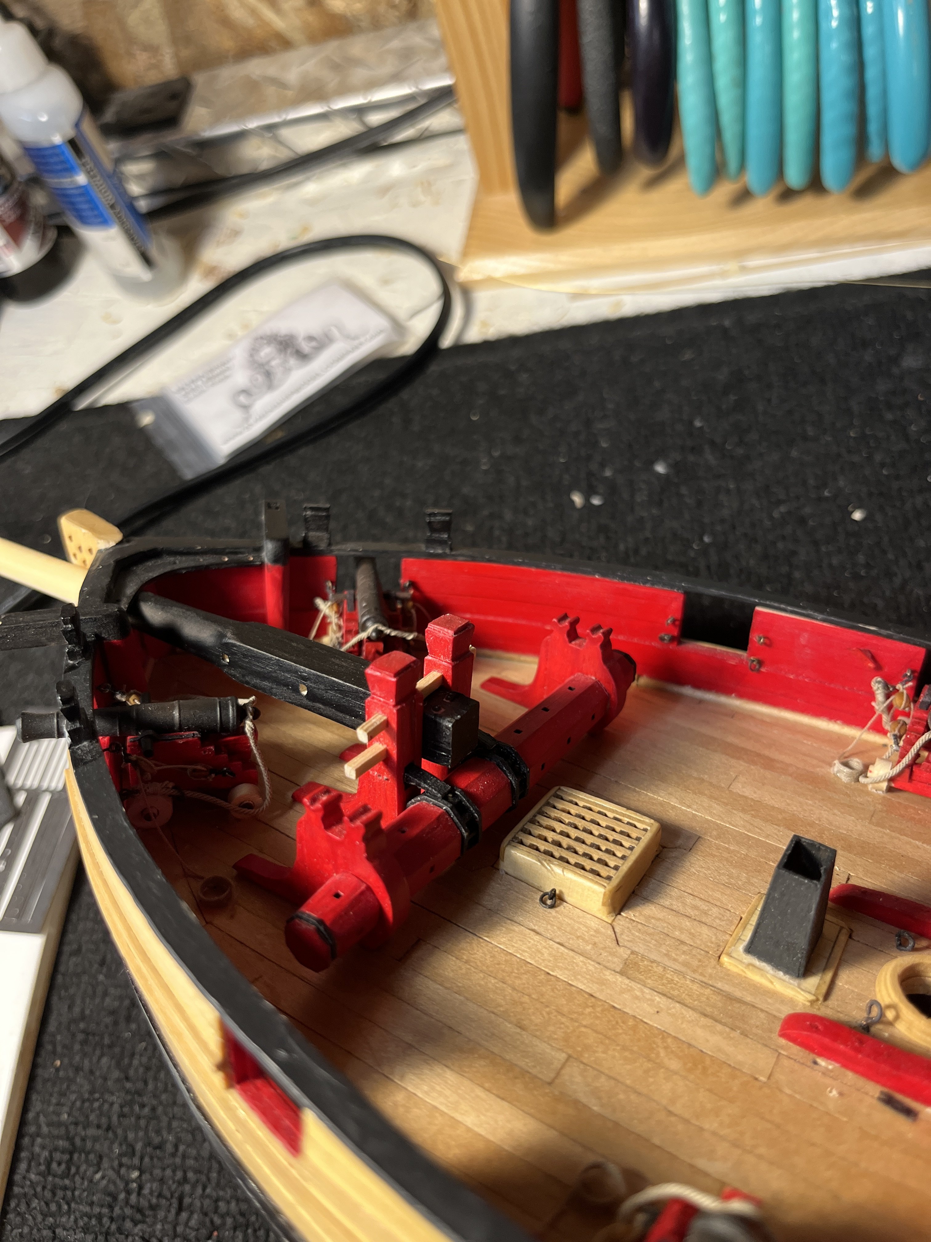
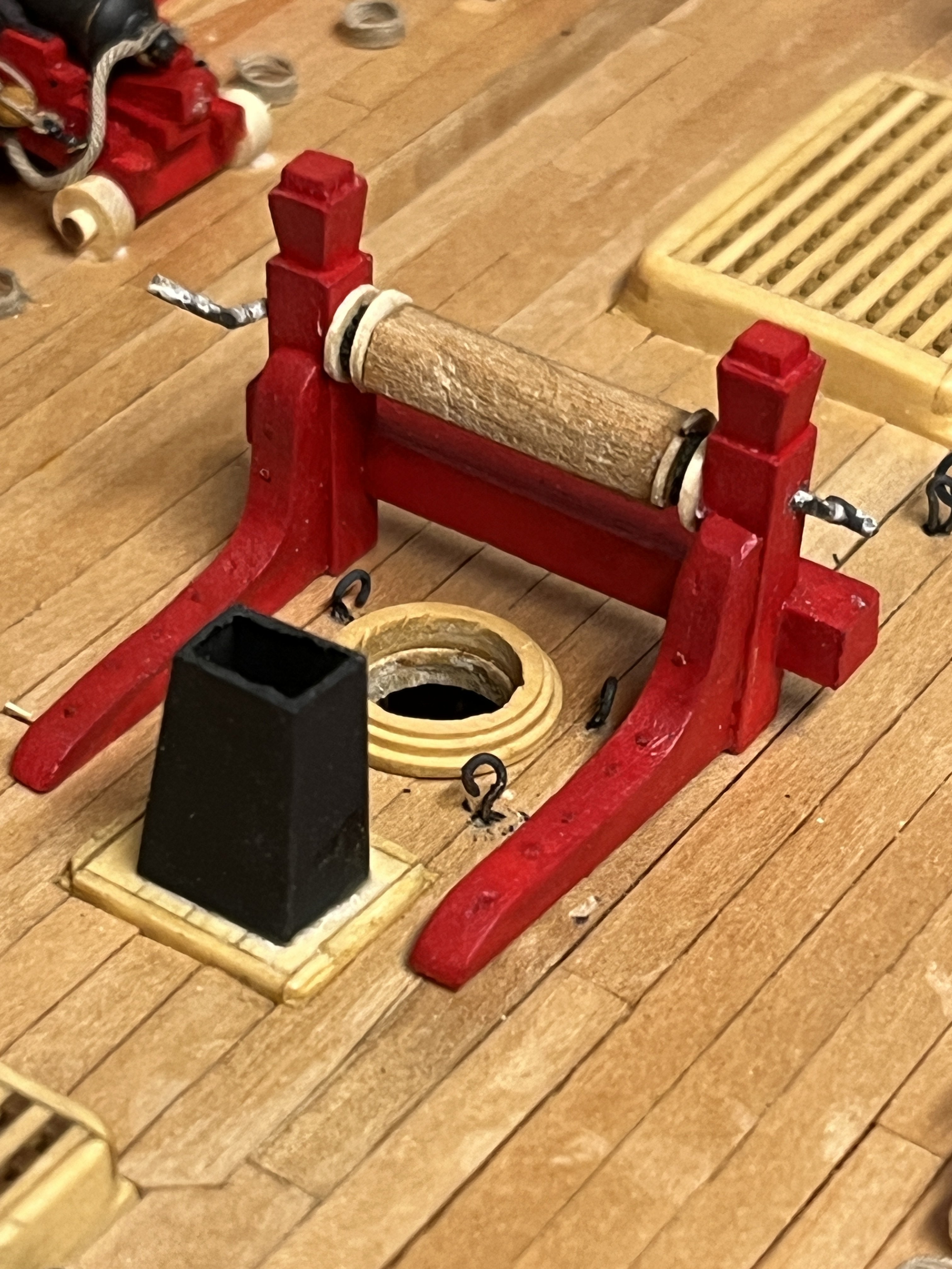
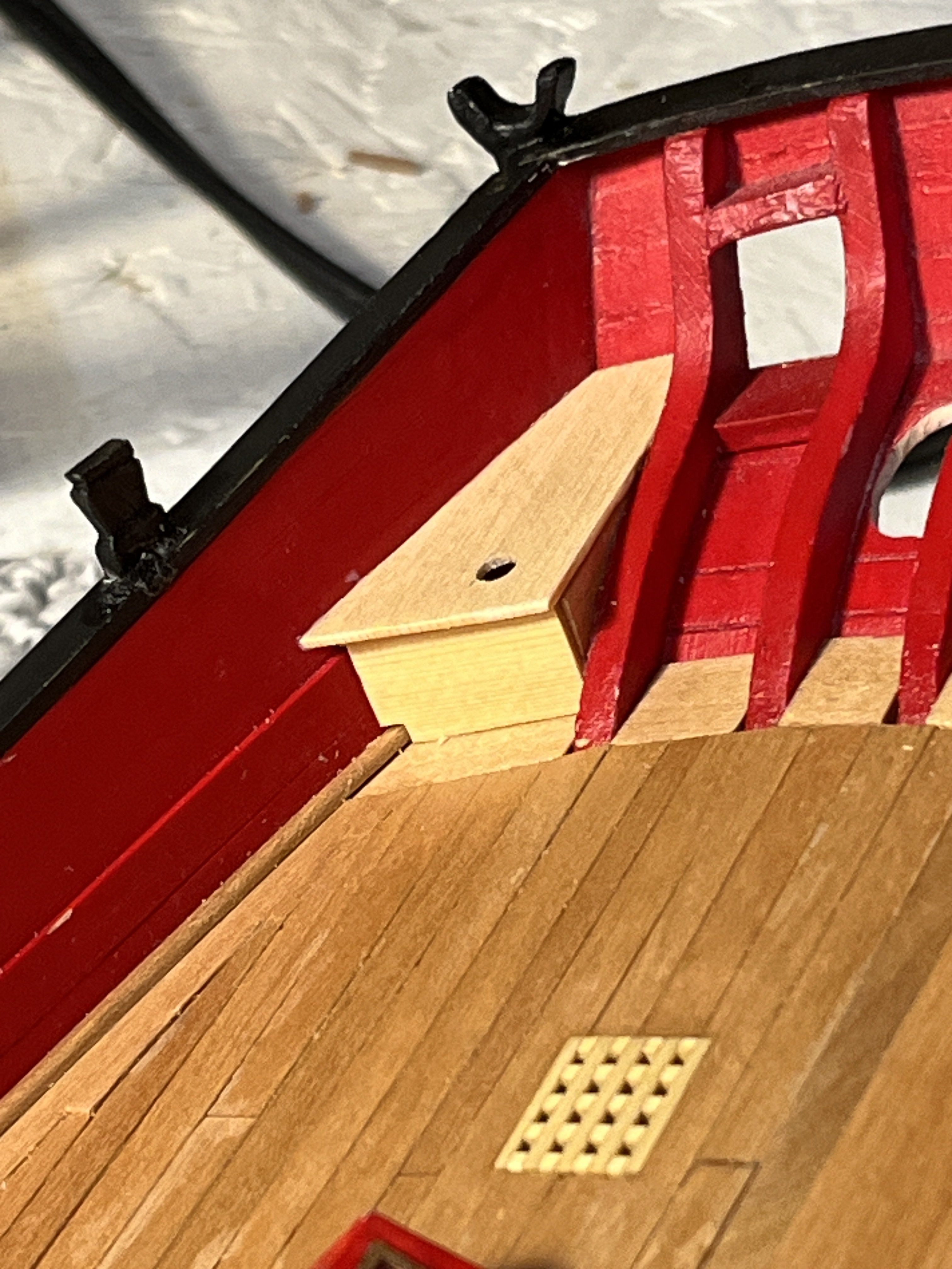
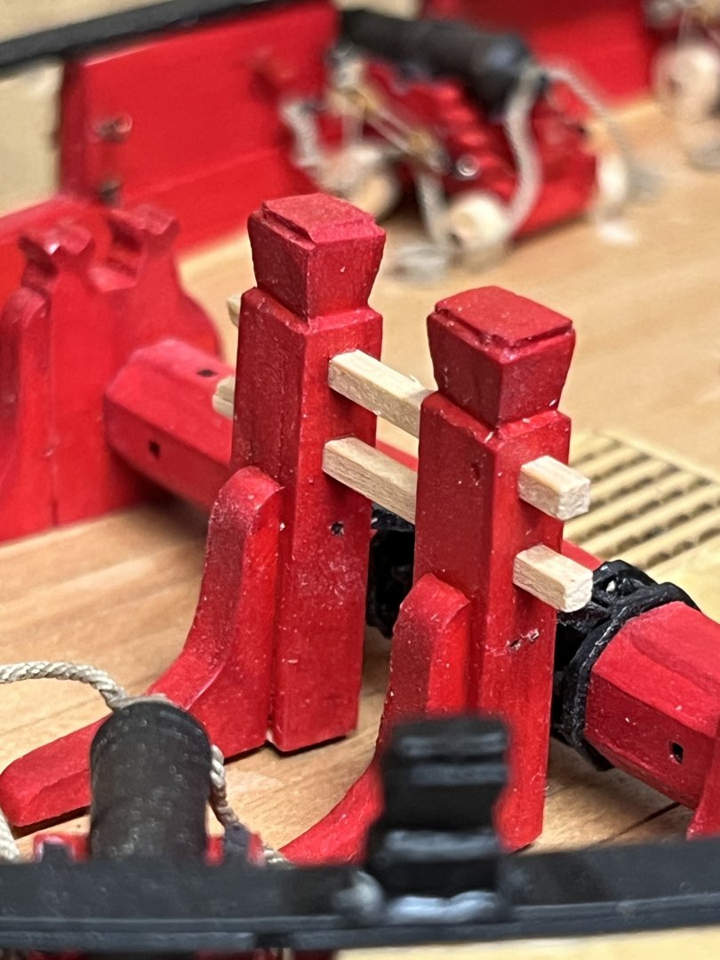
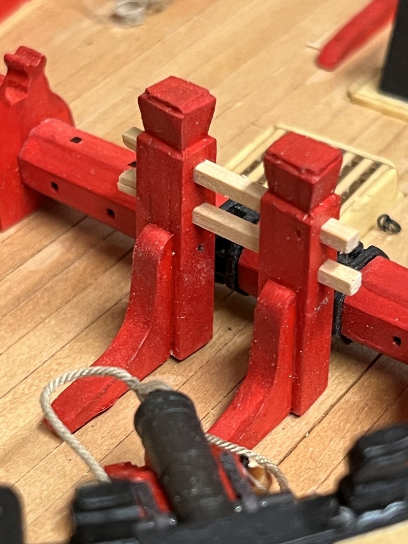
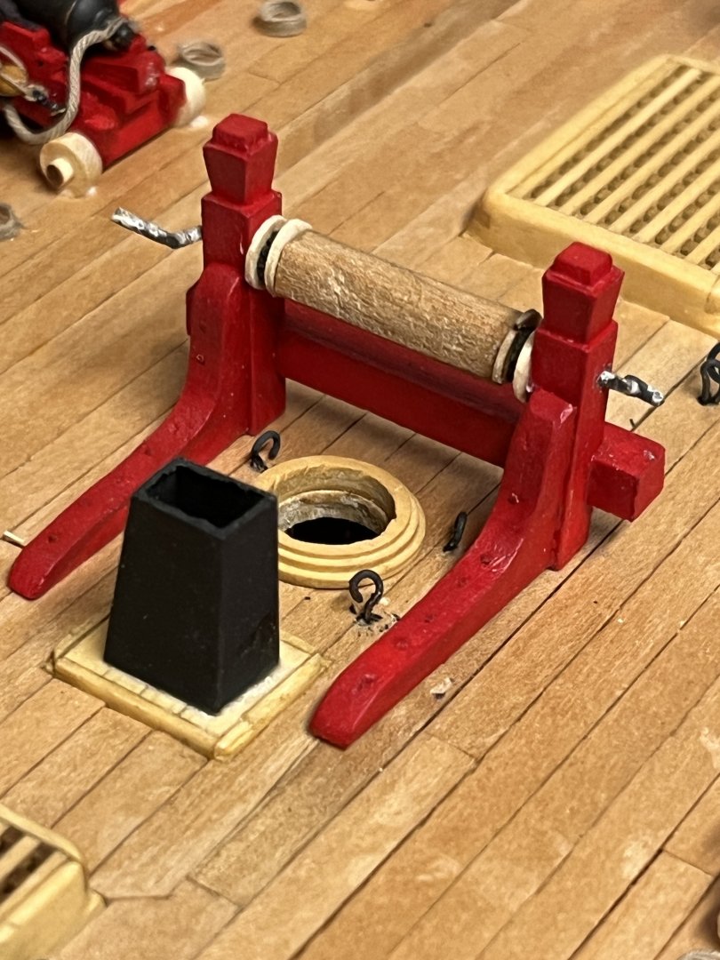
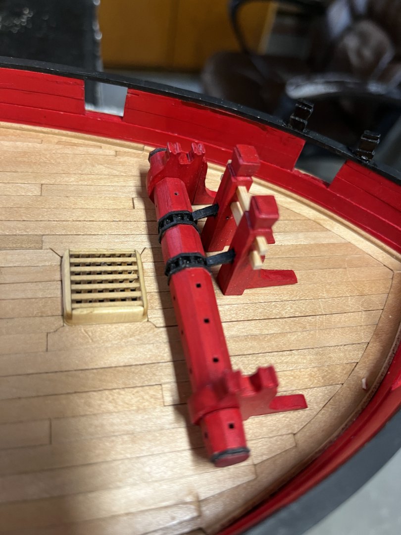
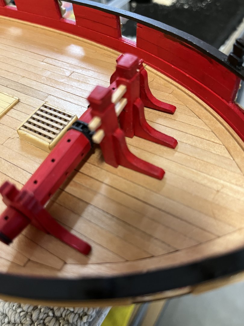
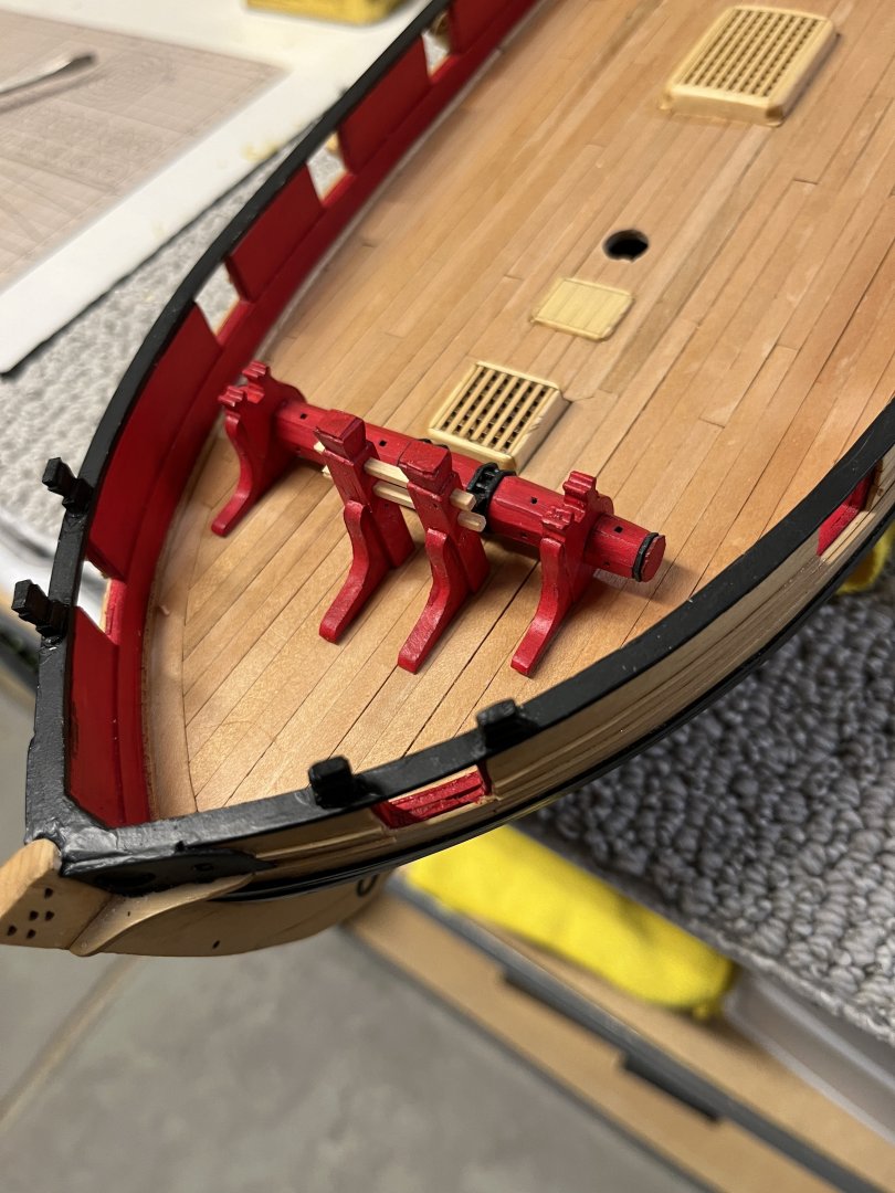
Back to working full time on Cheerful. Finished the windless which was started some time ago. I'm not sure if I mentioned that the small assemblies are Syren Model mini-kits. Finished the bowsprit step and finally got everything painted. Windless and bowsprit step in place not glued until the bowsprit is made then the parts will be pinned and glued to deck. and finally finished painting the seats and cleat

-
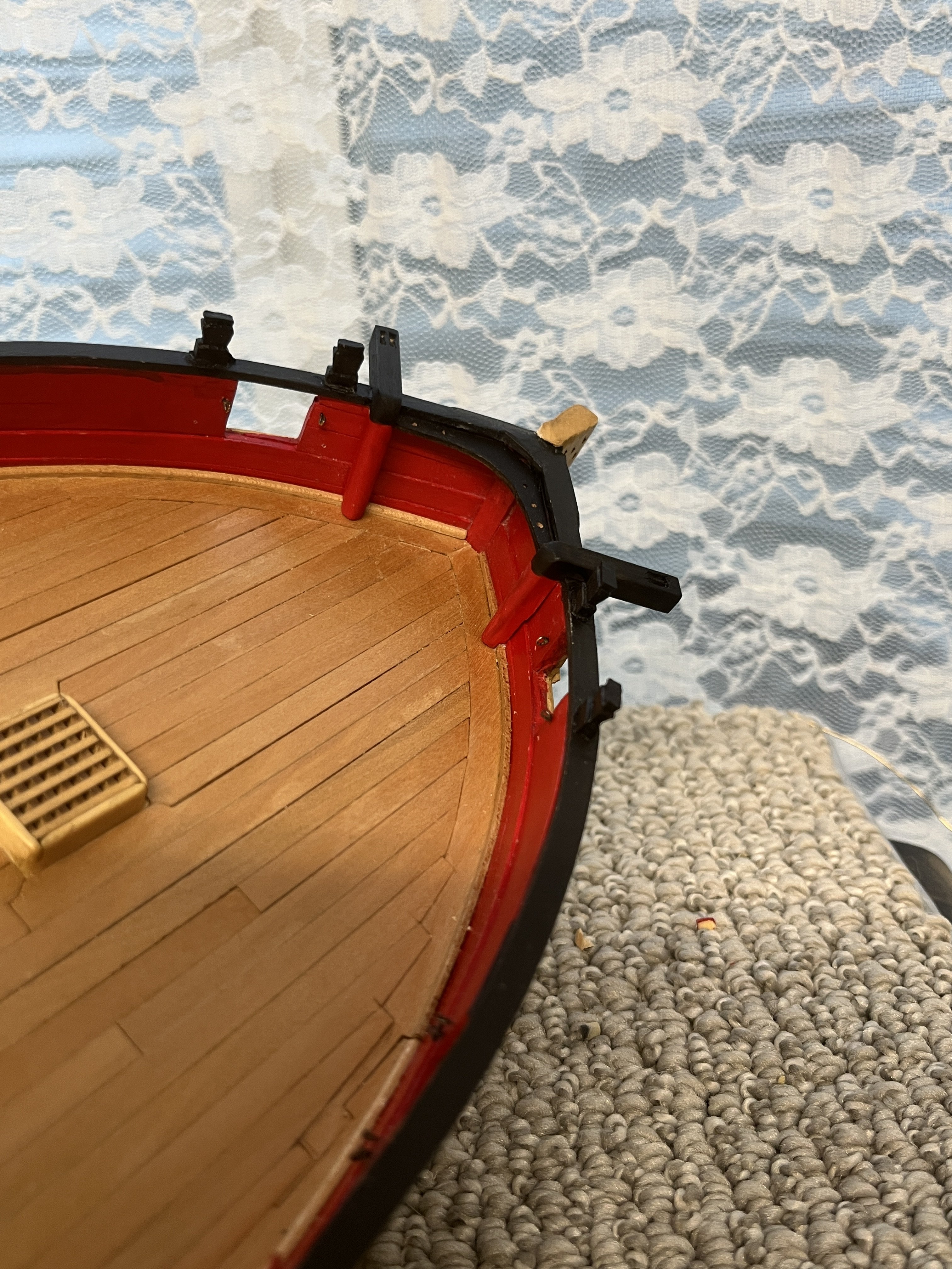
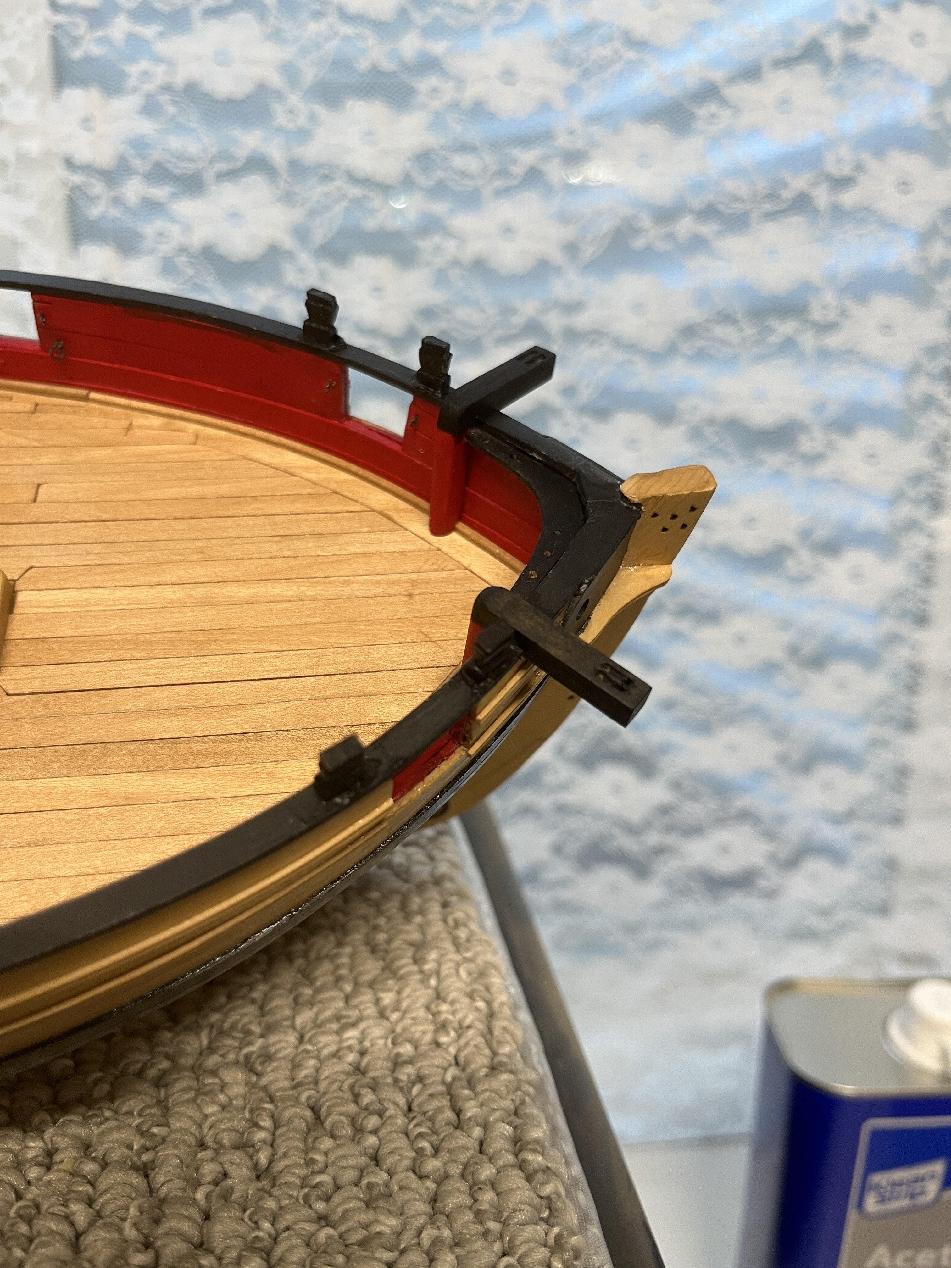
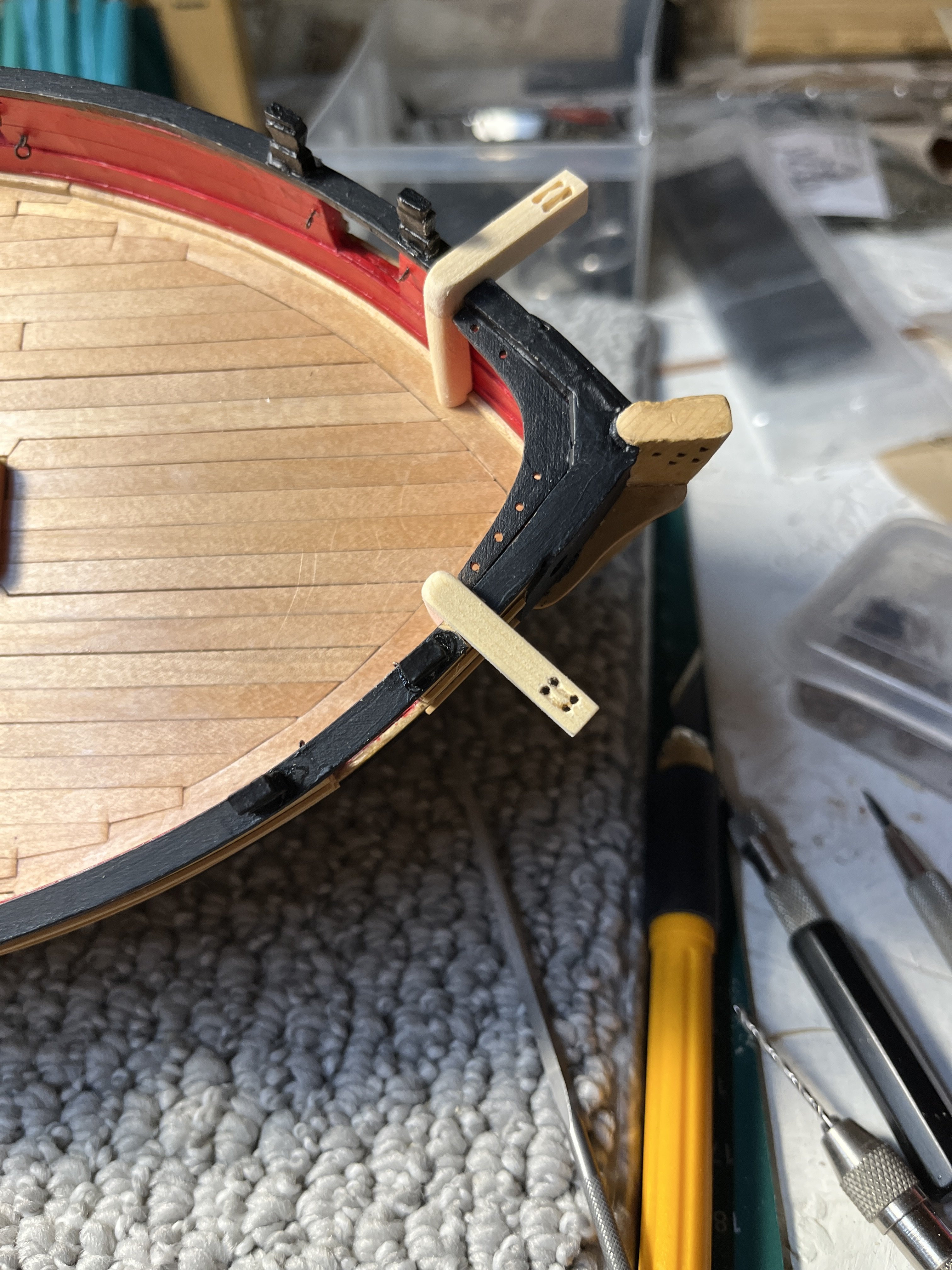
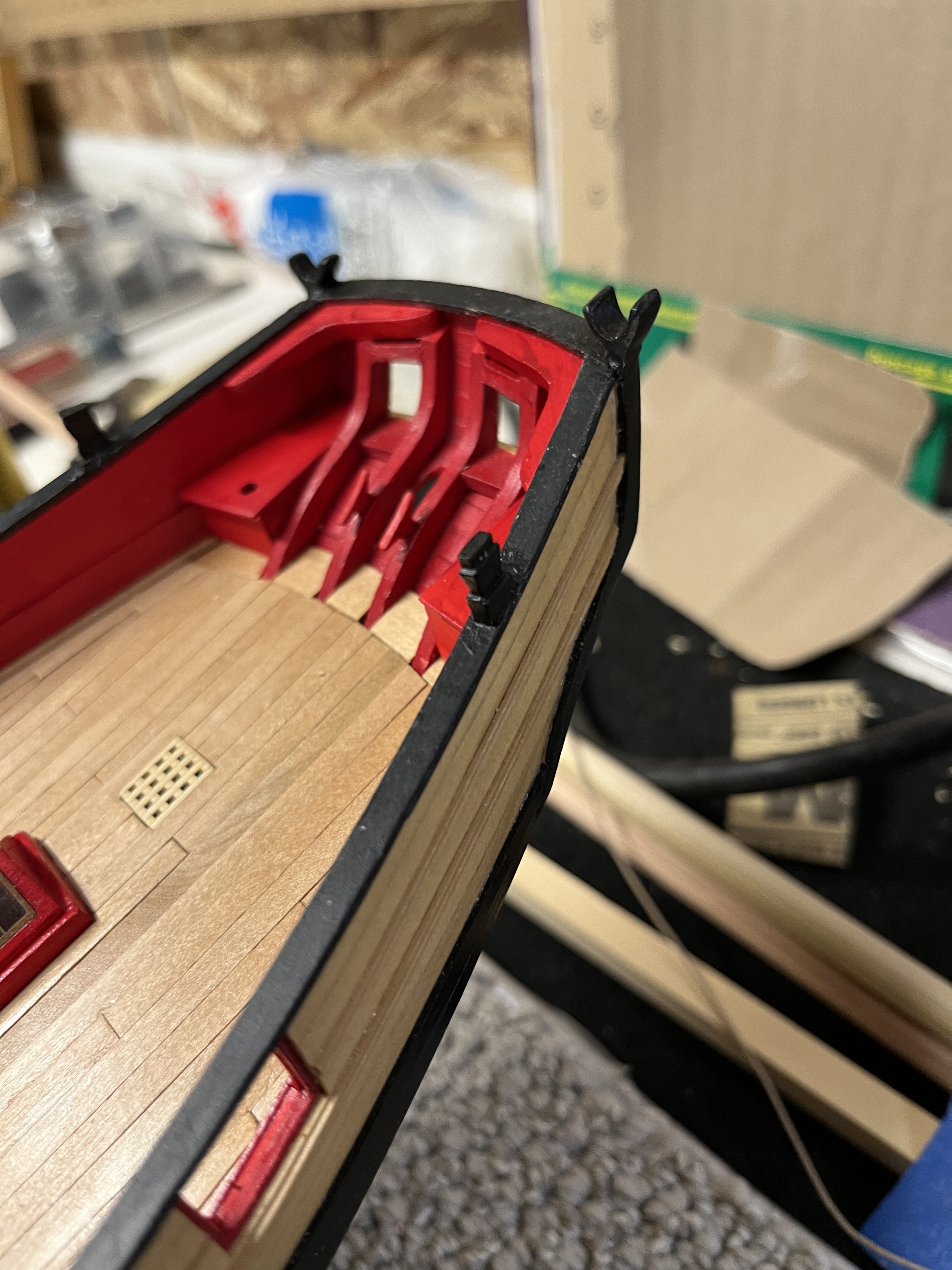
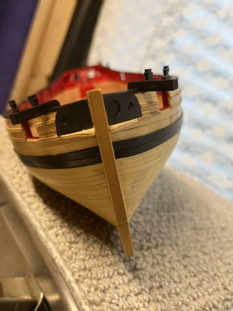
Just back from a wonderful vacation. Started in Quebec City for a marvelous 3 days of touring the 17th century city. Walking in Quebec City is a lot of hard work as it is very hilly as everything is uphill from the St Lawrence. We watched the 32nd stage of a professional bicycle race just as I think the Tour do France would be. Hundreds of racers team sag cars etc. The did 16 laps up and down the steep narrow streets, just amazing. We boarded a cruise to Nova Scotia and then down the coast to Boston where we rented a car for 5 days in Maine. Staying in Boothbay Harbor as our home base to explore. If you get the chance go to the Maine Maritime Museum we spent almost two days so much to see. Bath ME is the home of the museum on the grounds where many ships were built. In 1909 the largest sailing ship built in the US was launched and the ship was lost March 1924. Wyoming was a 6 mast schooner and was 450 from tip of bowsprit to tail of after boom. To understand the size of the Wyoming a steel sculpture was made to it exact size. Spent time trying to remember what I was working on prior to vacation. Then spent too much time to find the cleats from Syren Model Ship and yahoo I found them in the Cheerful tub of wood and parts. Sanded the largest cleats to shape and drilled a hole for a brass wire. Drilled a hole in the stern frames and placed the cleats with superglue. looking at the photo I see more shaping needs to be done
-
A lot has happened since last post. First the knees were sanded and into the final fit and the first coat of red paint to seats and knees and then preparing for a vacation trip to the east. First three coats of red paint in the spare time. Now on to vacation

-
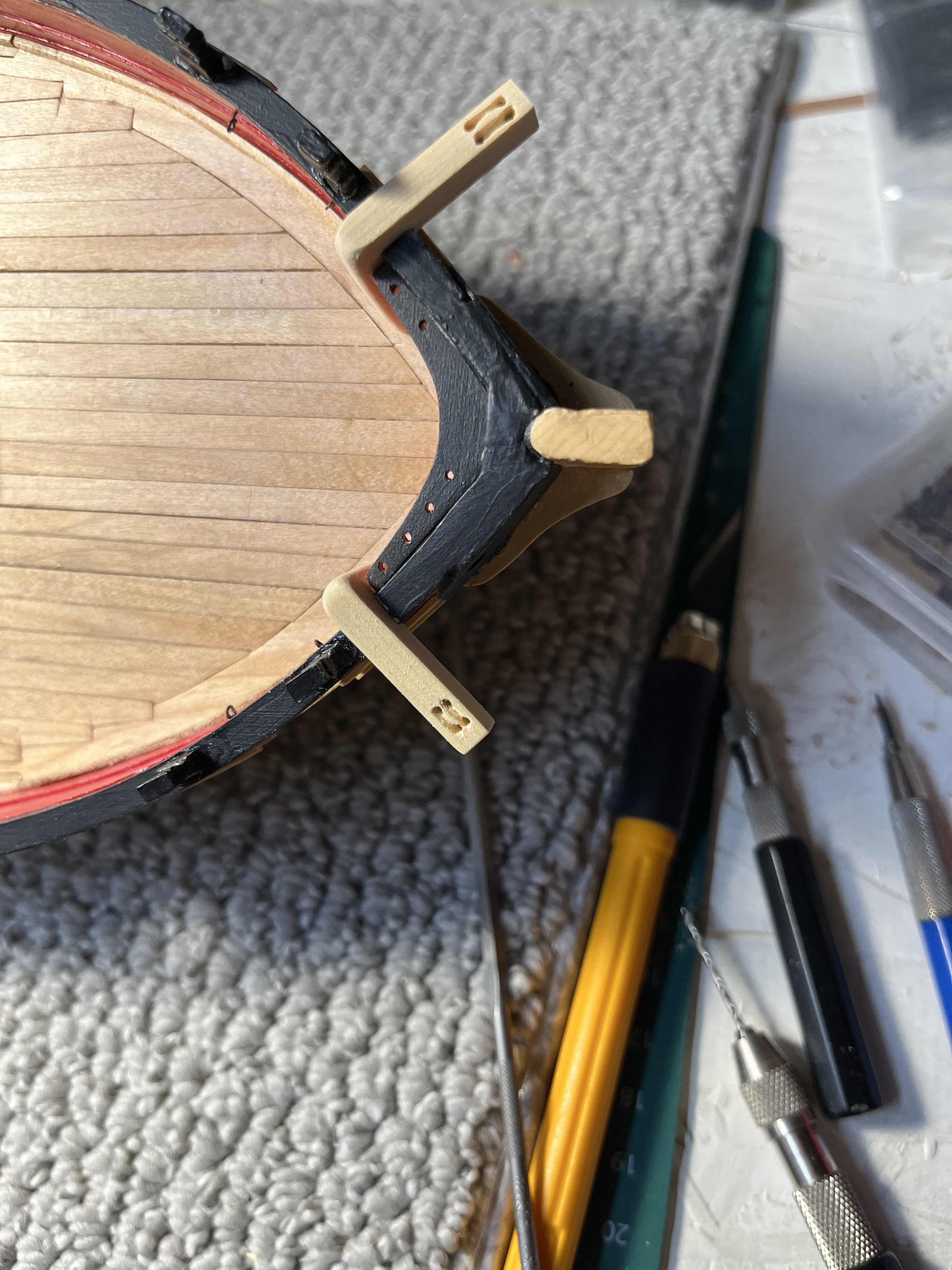
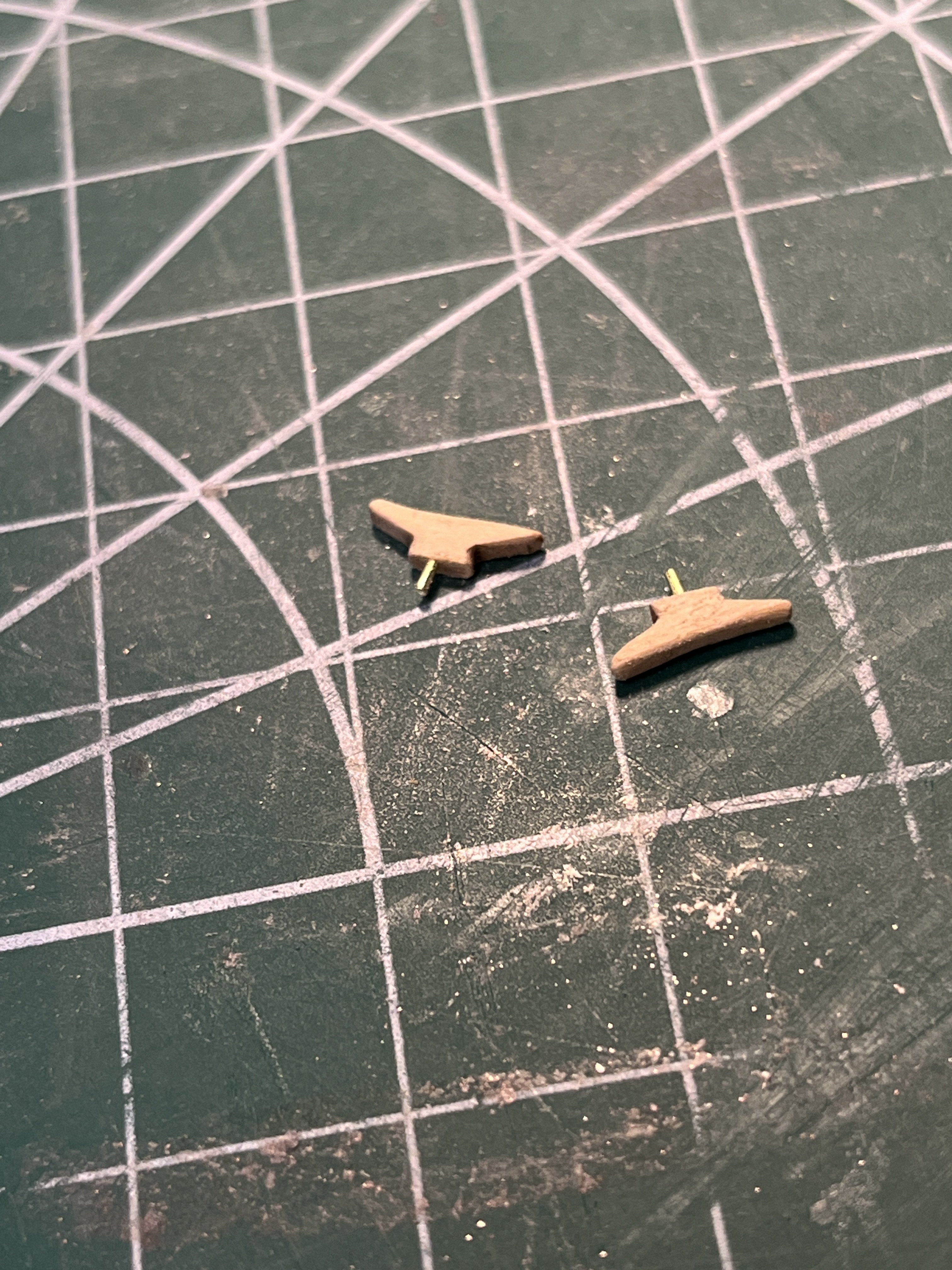
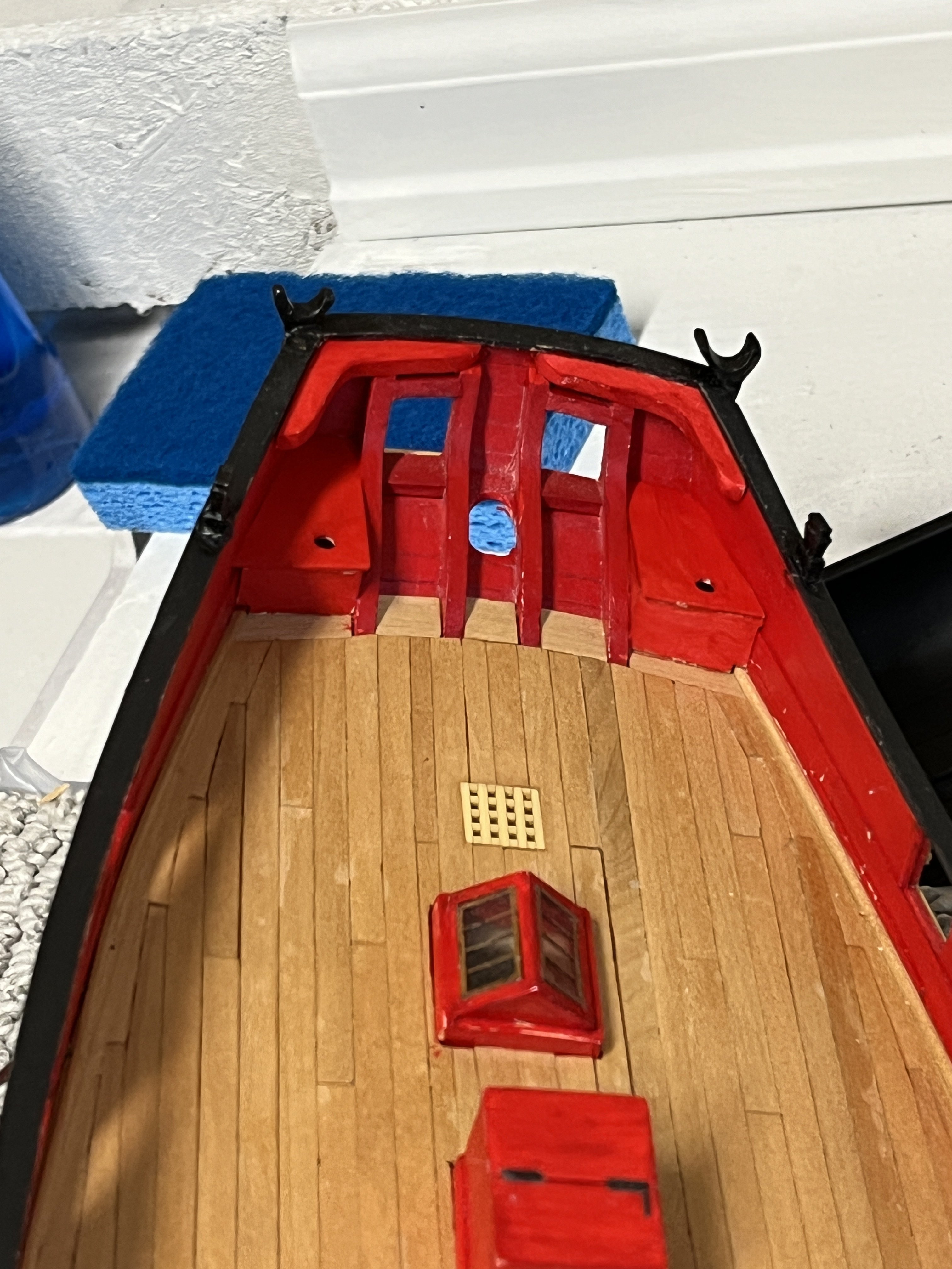
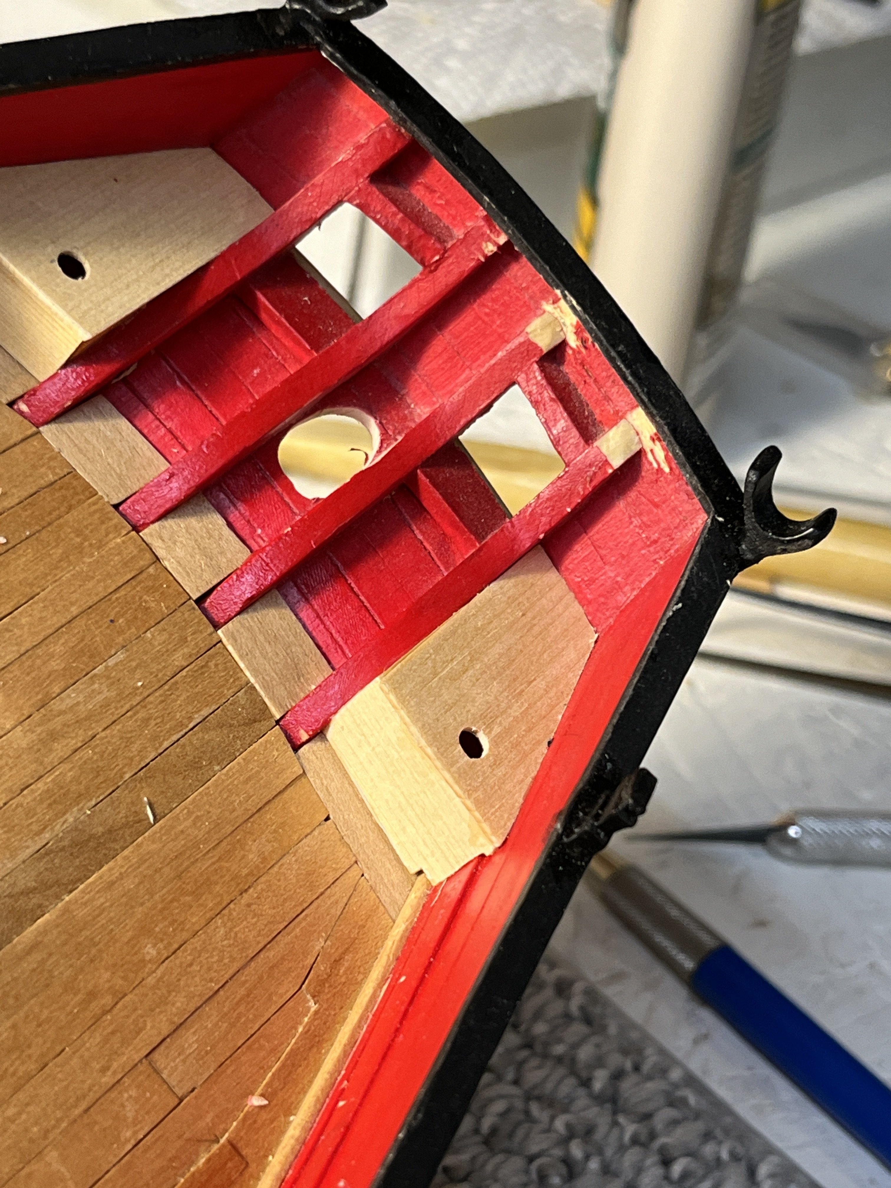
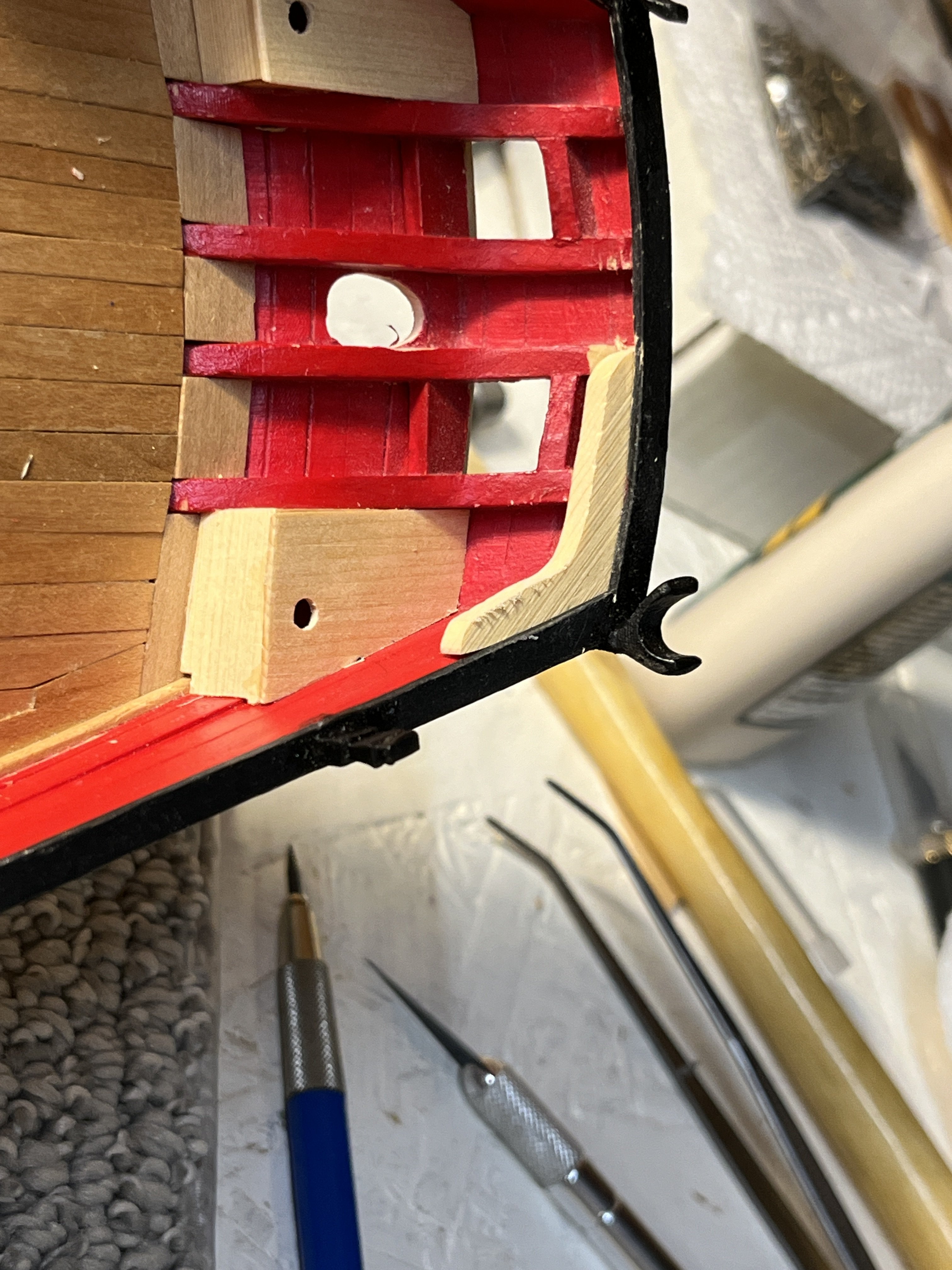
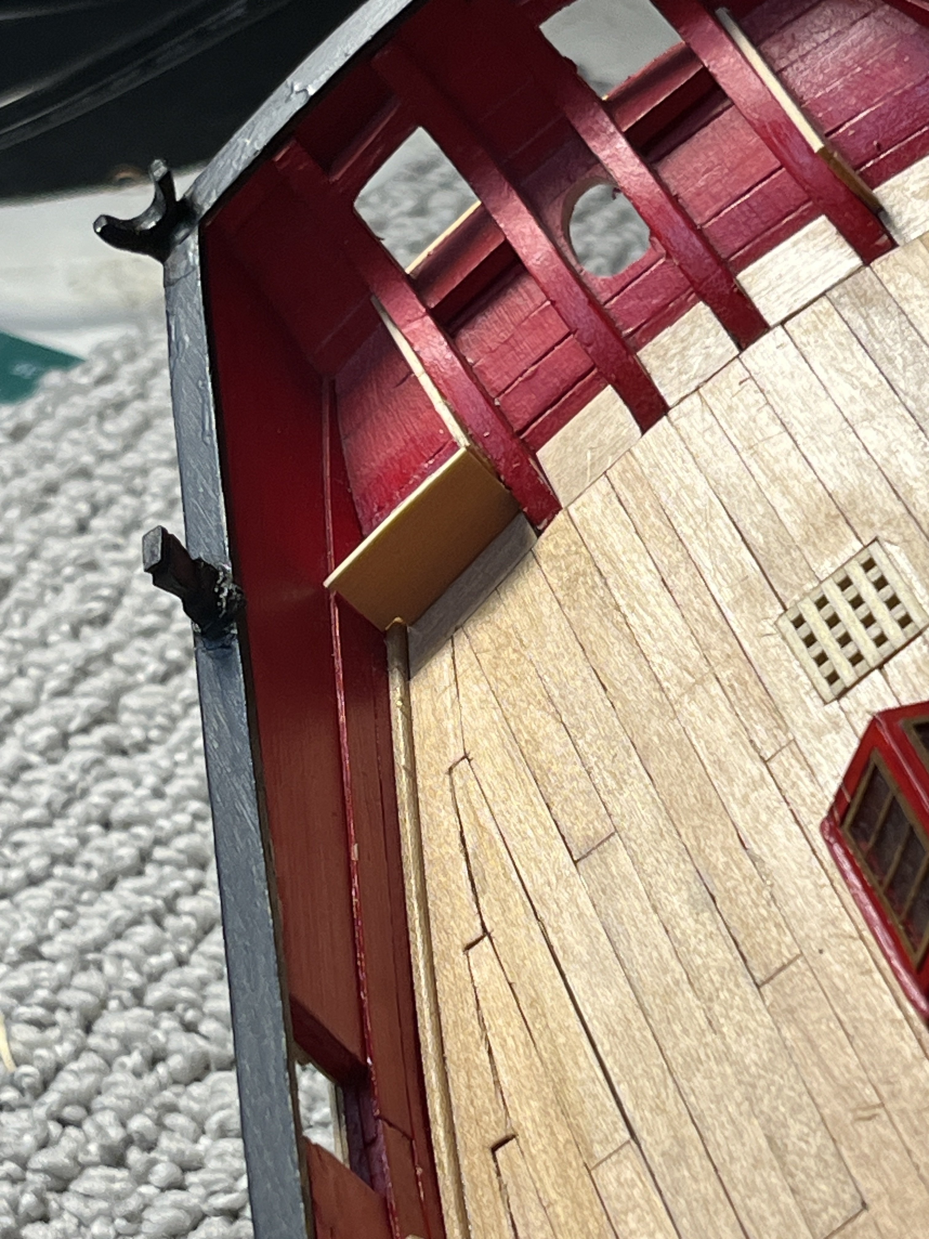
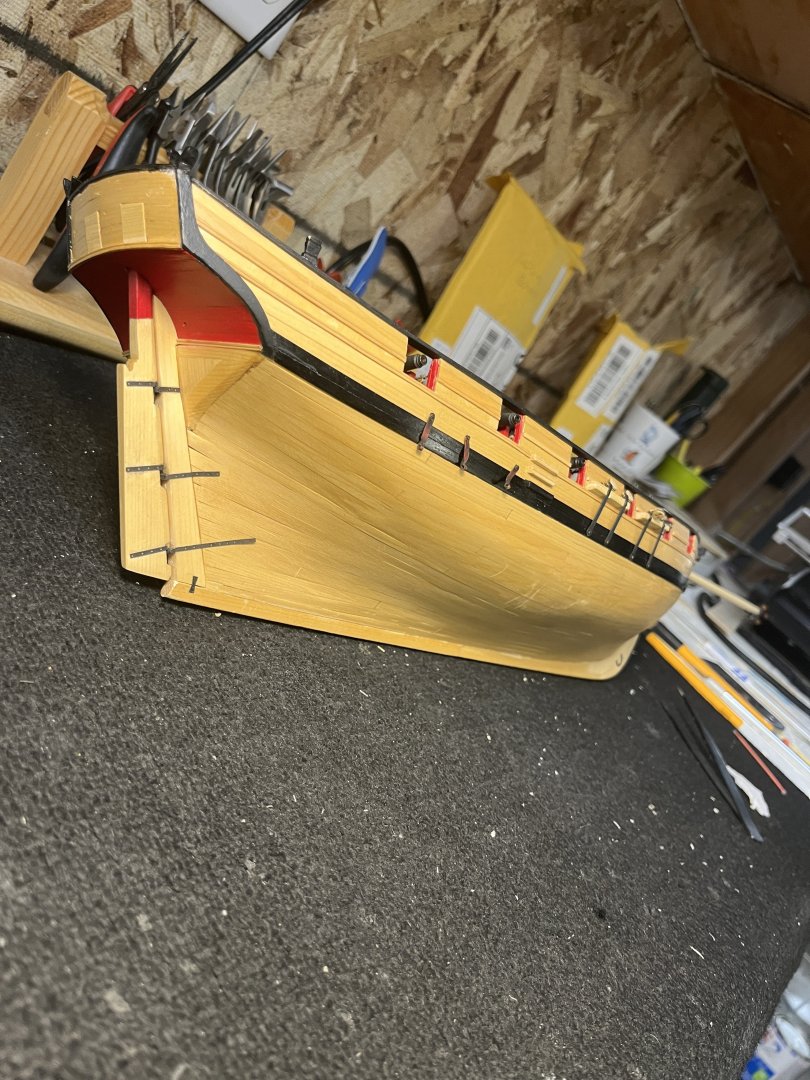
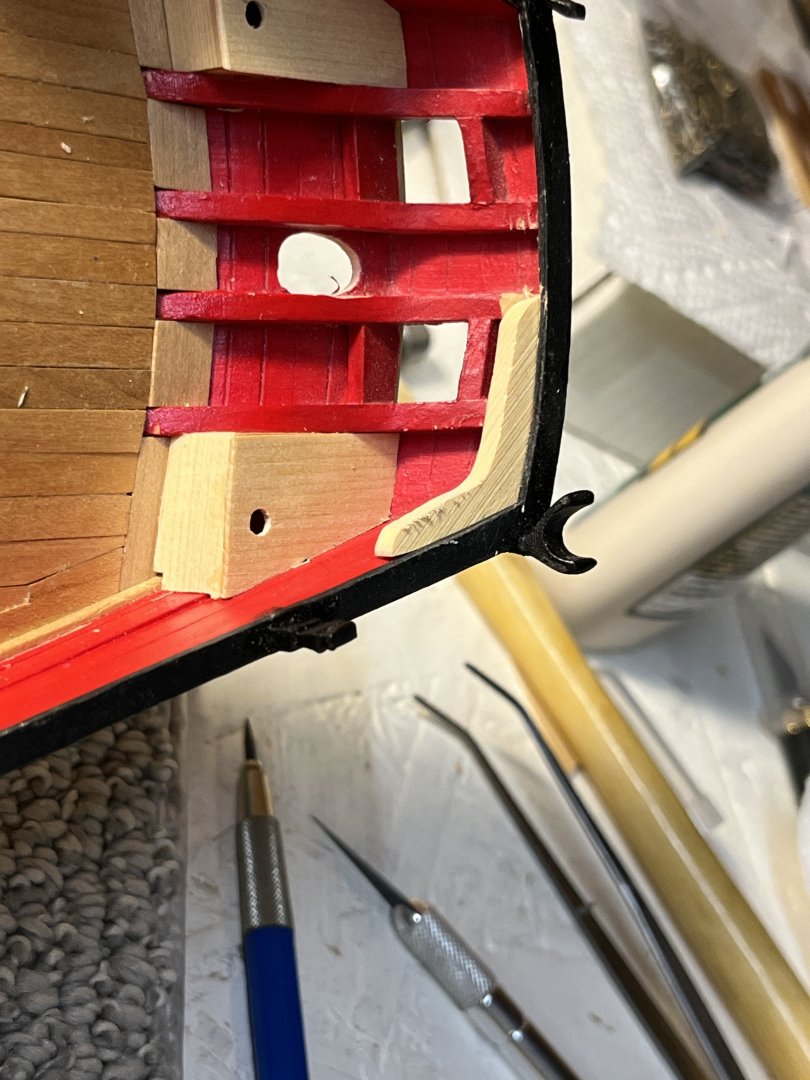
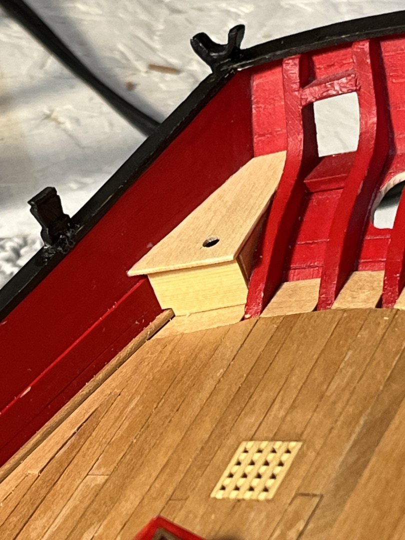
Transom knees simple parts to be put into place, RIGHT. First thing is studying the plans and others building logs. Finally found a post that had actually shown the process of modifying the the transom frames to allow the knees proper seating. Again using the plans I made a card template to mark the knees unto the wood. Cutting the knees from the wood with the scroll saw making sure I left sufficient wood beyond the pattern for shaping. Using the knee I started the nerve wracking process of cutting the frames. Using a new blade thin slices were cut until the knee slid under the cap rail. When both frames were cut I carefully started slicing the frames allowing the knee to fit under the cap rail on the side. As you can see no matter how carful you are the cutting process left a mess. Next taking the knee and started shaping to the final fitting shape. Sand test, sand test, sand test until the knee fit under the cap rail and flush to transom and bulkhead. Starting knee from saw. Knee fitted ln postion ready for finish sanding and gluing into place. This whole process would have been much easier before the boom crutches and timberheads were attached. I kept fearing the I'd knock one off damaging the mounted surface with the securing pin.

-
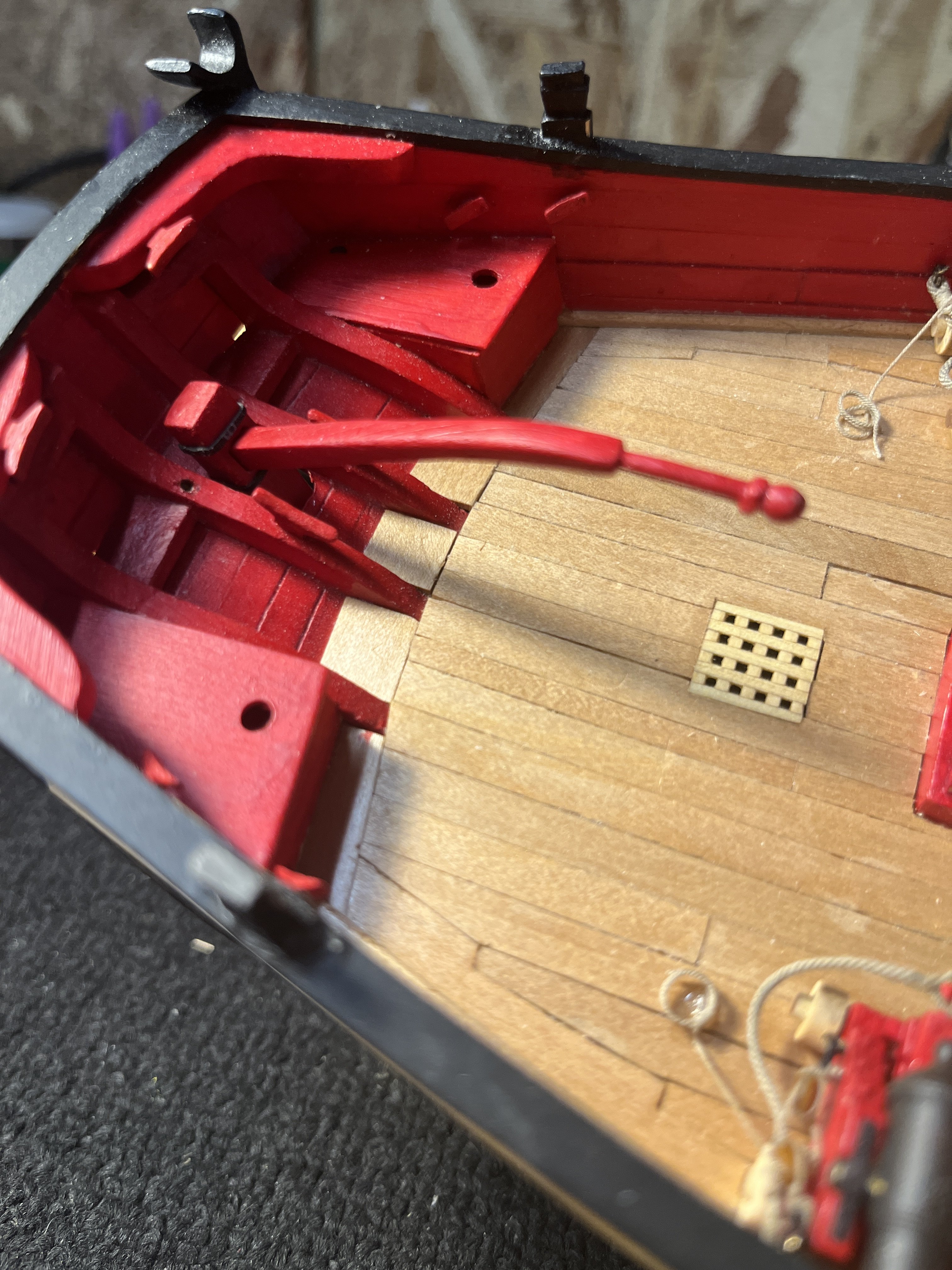
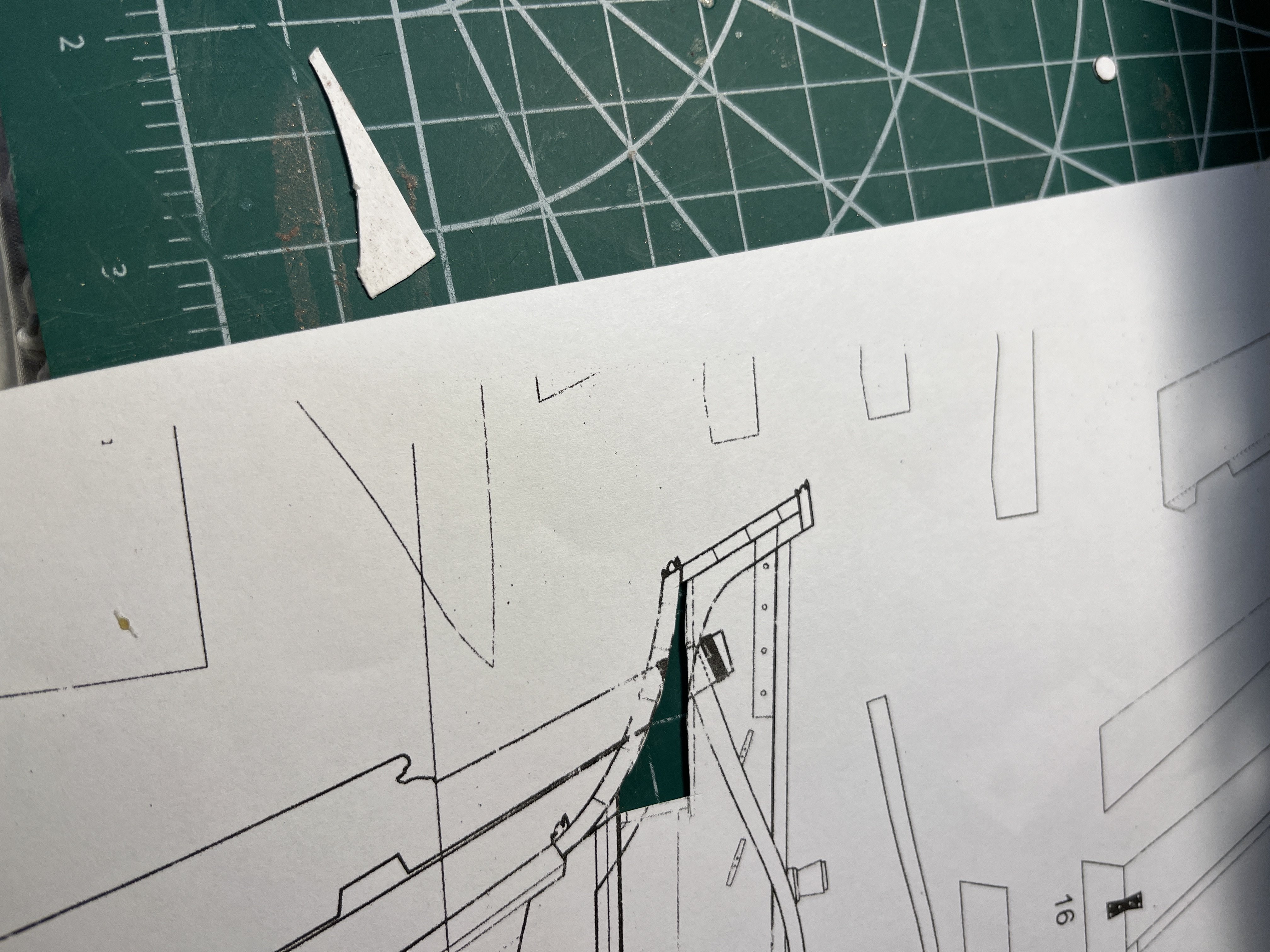
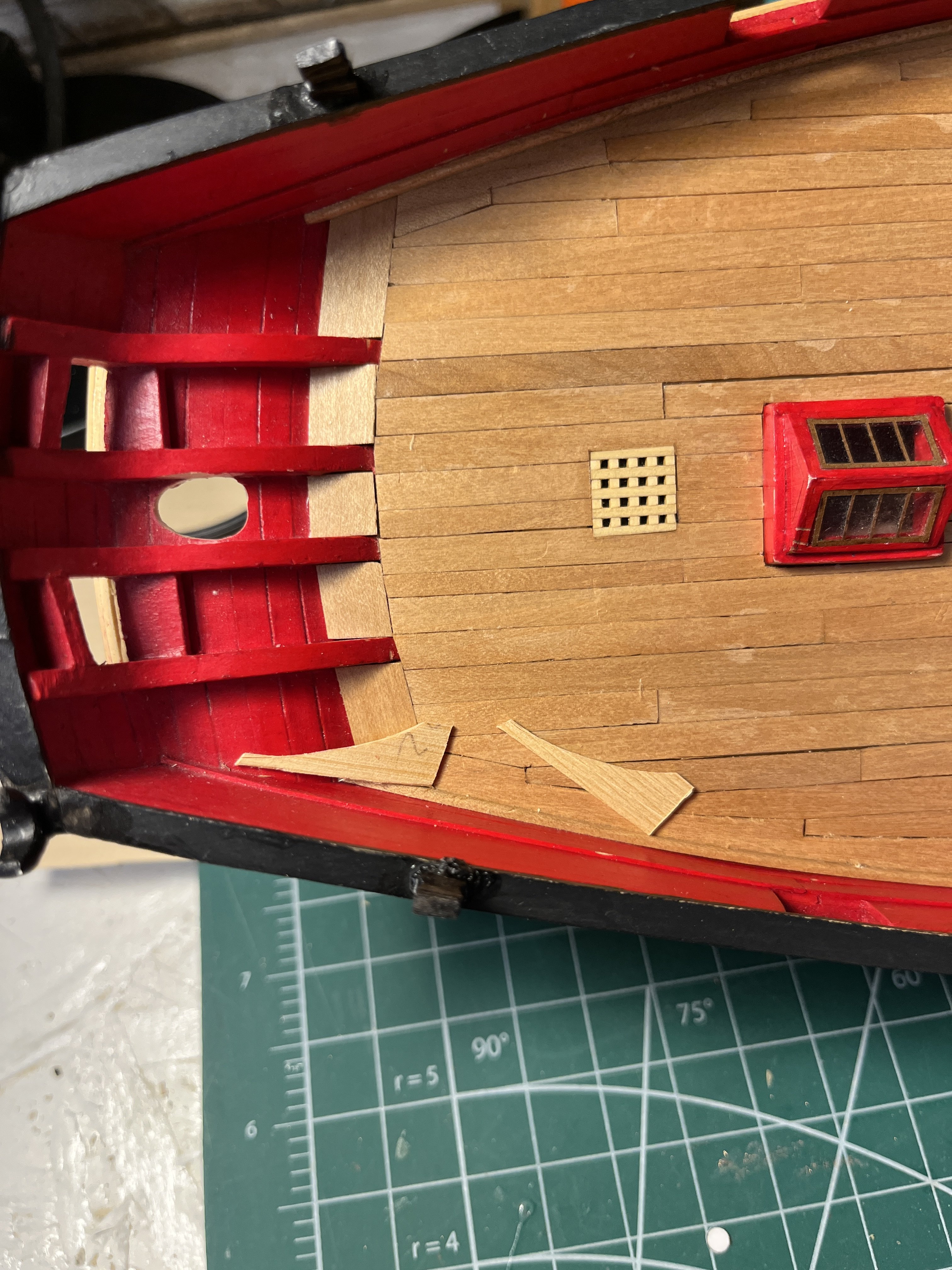
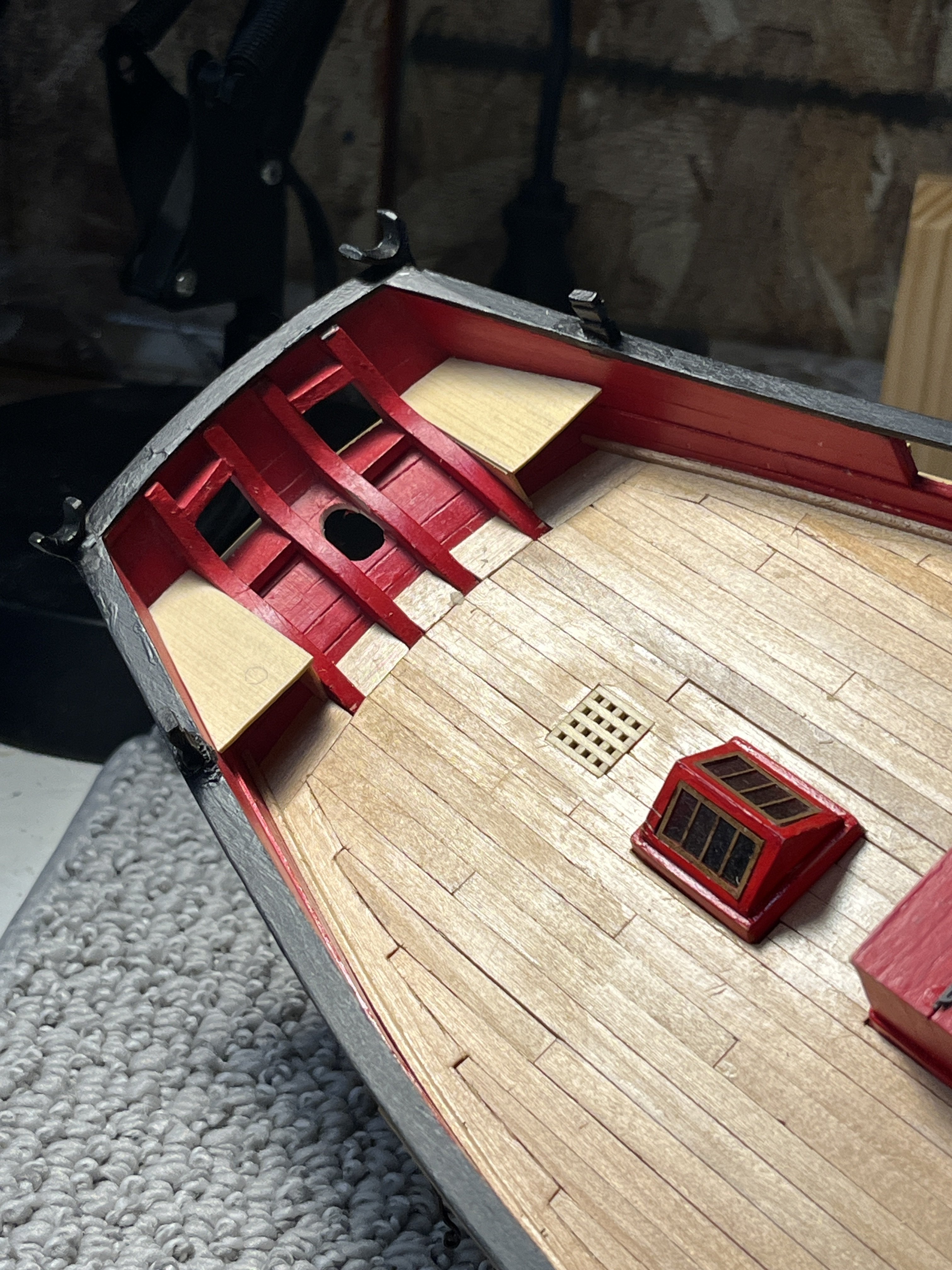
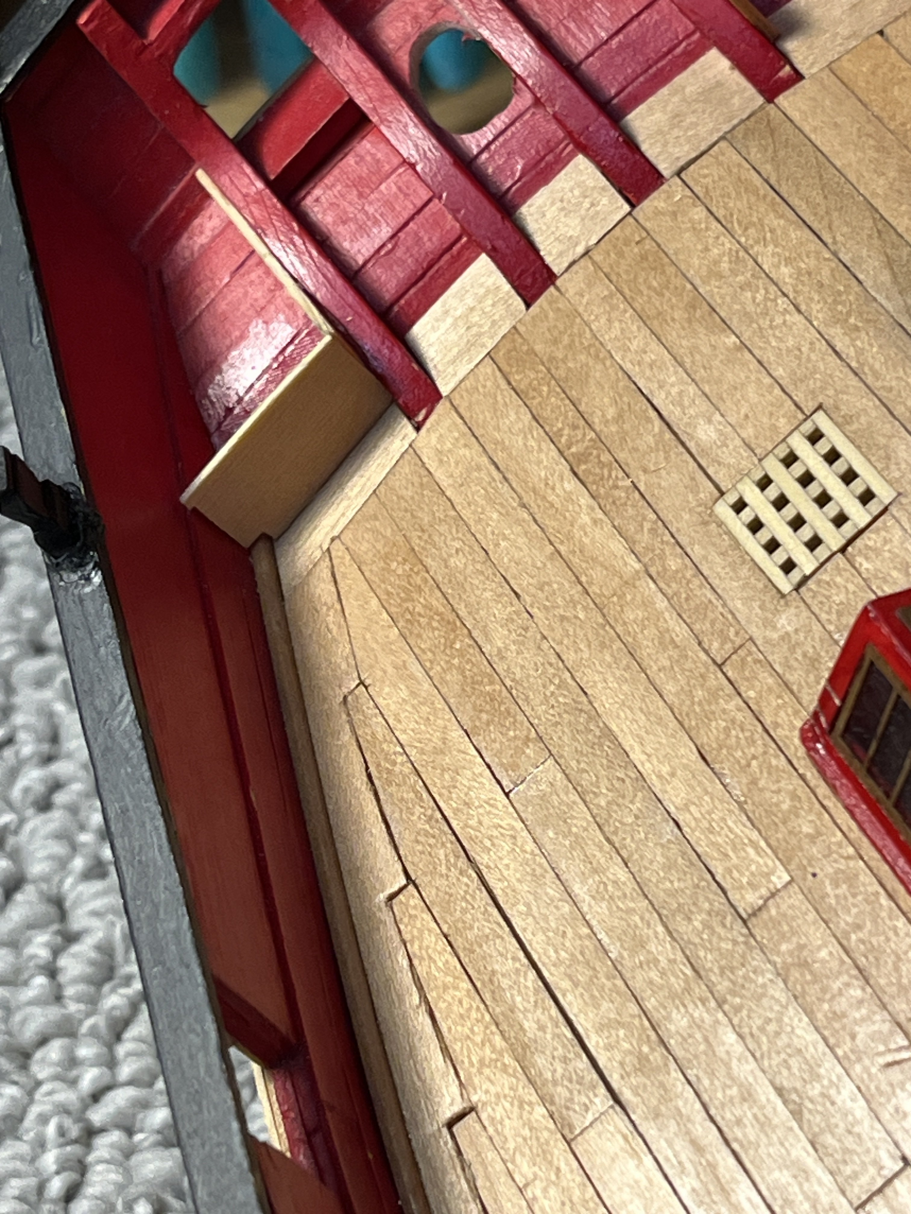
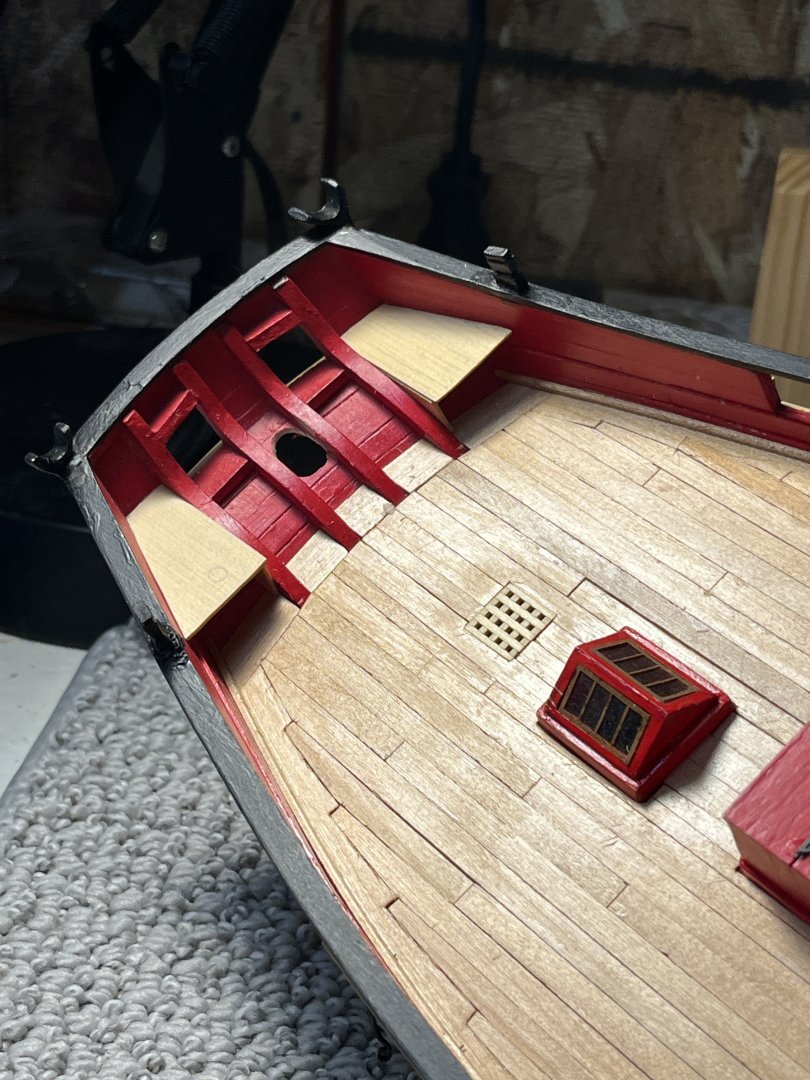
Chapter 10 starts with the seats on each side of the tiller and the monograph suggests using the drawings (which are in 1:48). I made copies of the top view and the side view on the drawings making copies without cutting up the original drawing as only one copy was furnished. First was to plane a sheet of boxwood down to the 1/32" thickness for the seats. Once ready I made templates of the inner side and top using the drawings as they are at 1:48 scale. Preserved the drawing by folding to fit on the copy platform. Using elmers school glue stick I glued the prints to a card from my wife's menu file supply. After cutting the card to make the patterns I glue sticked them to the wood. The copy with the pattern removed While the template was a very close fit there was still a lot of filing to get the radius fitting the transom. After glueing the sides using the same method the tops were sanded and filed to fit without any gaps The harder part was the front as there was no way to make the pattern so a piece of wood cut to basic shape was used. Starting with the inside piece being a straight surface the bottom was fit to the deck radius The inside of the bulwarks not being flat were the most difficult. Many attempts made, five to be exact, before a part was close enough to be used for final template and sanding. Last thing was the hole in the seat and glue it all together. One side done with templates for the port side to start with fitting. Tomorrows another day and woodwork is so much fun after the strops and chain plates.


-
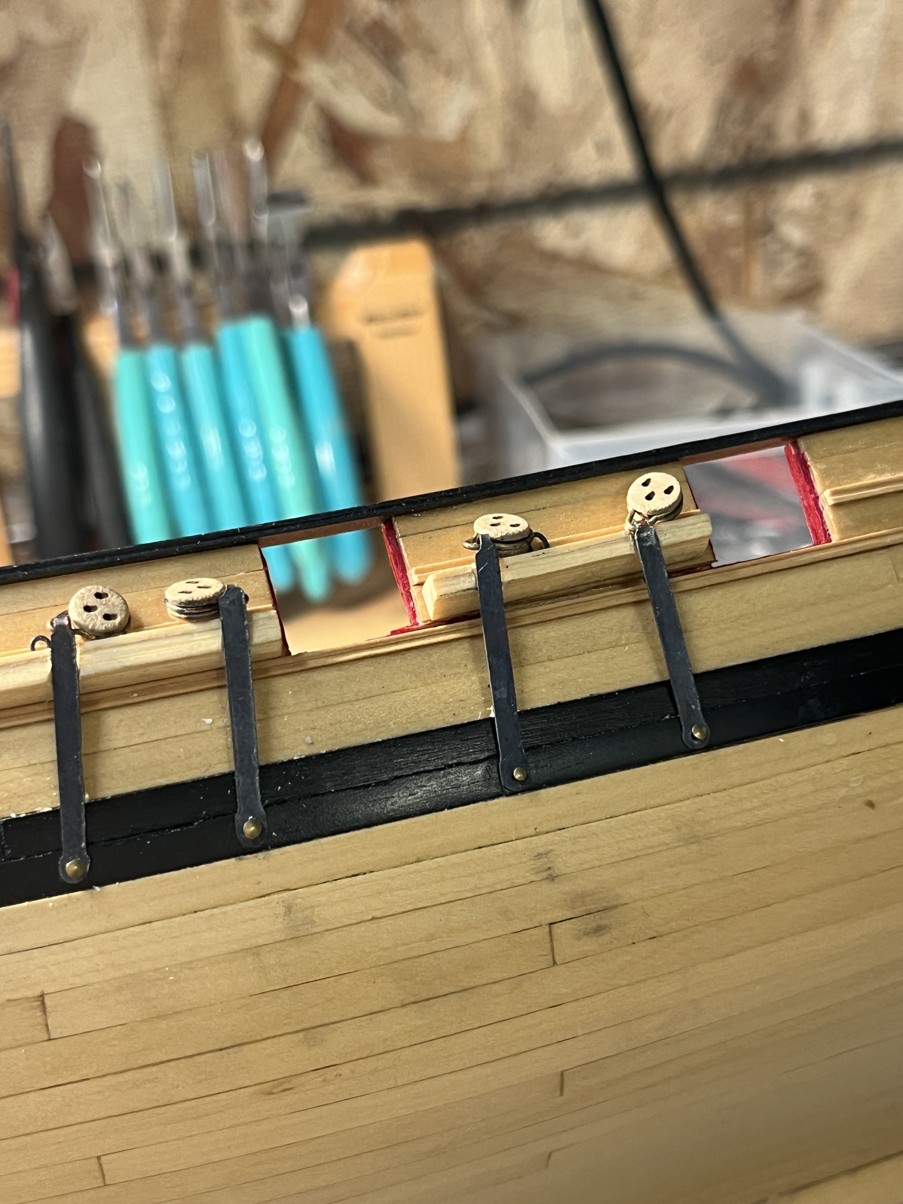
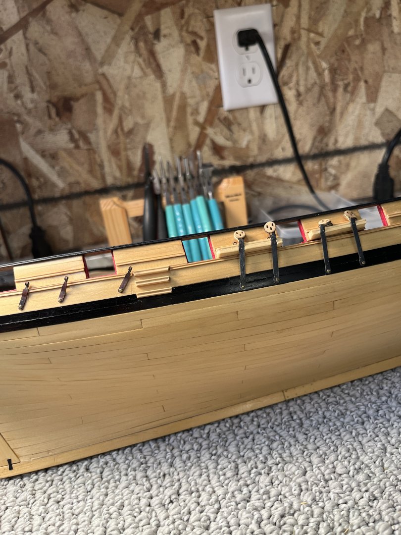
CHAPTER 9 IS COMPLETED!!!! Back stays and chainplates blackened and installed. These 8 parts have been one of the most challenging things of the Cheerful. The blalck smudges are easily wiped off the planking since the wop has made the finish sealed and very smooth. The process of making the deadeye strops the same length and shape was a days work. The chainplates brought their own problems of length, shape, and loop. Getting the lengths correct so the deadeyes all align with the top rail was completed with many parts in the bin. Finding a needle nose small enough to make the loop another process until finding the pliers from a jewelry set allowed loops small enough to appear correct in scale while fitting the strops. I found that if I annealed the chainplates this allowed the bending of the loops without distorting the chainplate. Four days of mind bending work later it is completed. Chapter Ten is mostly woodwork so this will be better on my soul and mind.

-
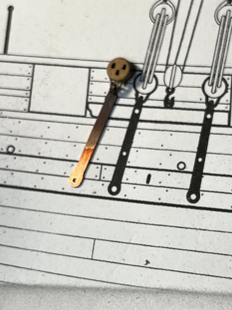
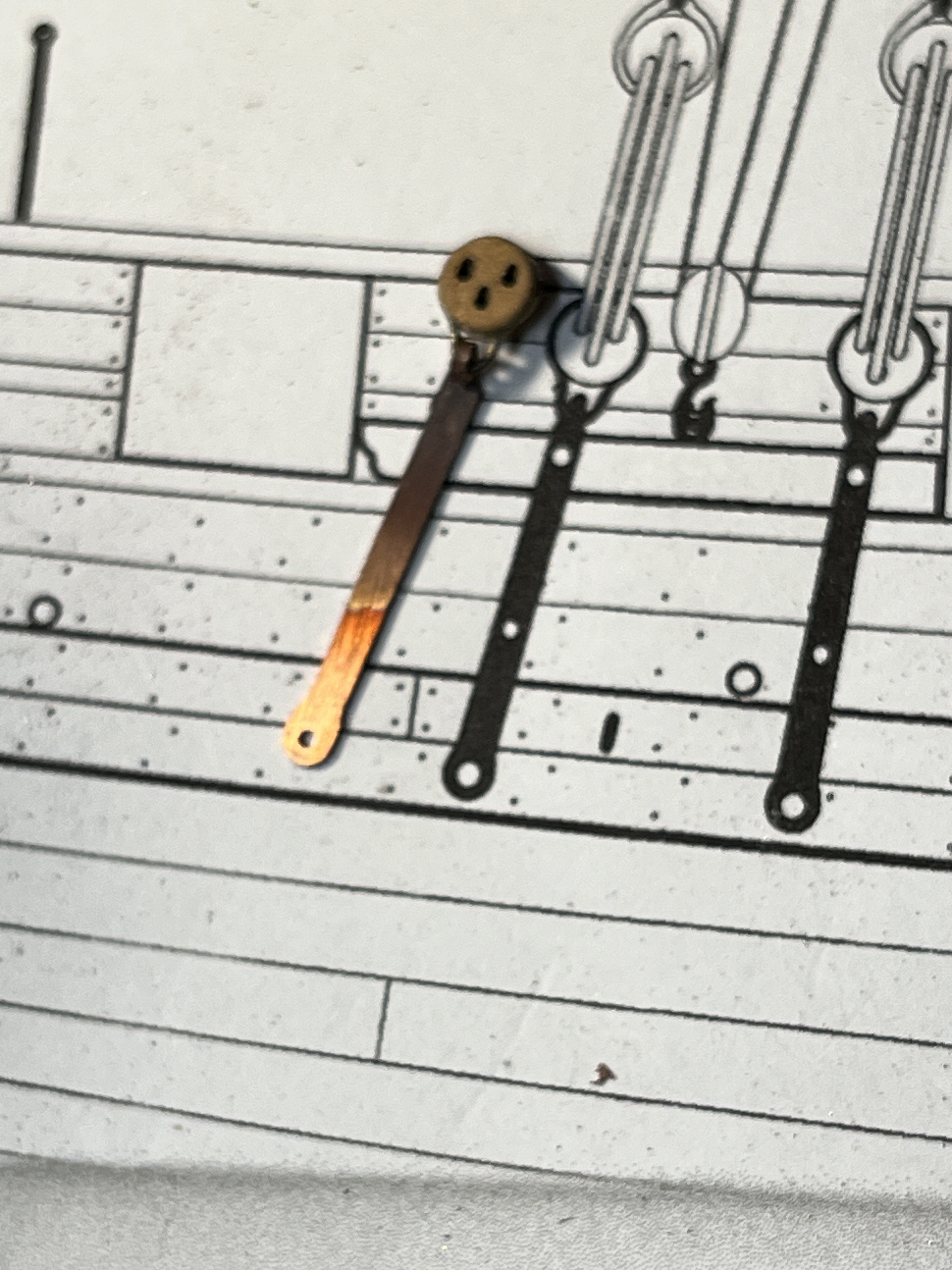
Now with the deadeye strops ready for finishing I started on the chainplates. Using the same methods as the backstays I made the 8 chainplates. I just realized that it has been a month since my last post as I was in Arizona visiting my daughter along with a little holiday travel so the last two days have been filing the chainplates and now the backstays and chainplates are ready for blackening. Just a photo of one aligned with the print. Next is to blacken the parts and then make a simulated mast so the chainplate angles are determined with string.