

Bill Brown
-
Posts
65 -
Joined
-
Last visited
2 Followers

.thumb.jpeg.fc5d633a7b34428fcf19419a73d56d55.jpeg)
About Bill Brown

- Birthday 09/26/1960
-
 PaddyO reacted to a post in a topic:
HMS Cheerful by Bill Brown - FINISHED - Syren Ship Model Company - 1:48
PaddyO reacted to a post in a topic:
HMS Cheerful by Bill Brown - FINISHED - Syren Ship Model Company - 1:48
-
PaddyO reacted to a post in a topic:
HMS Cheerful by Bill Brown - FINISHED - Syren Ship Model Company - 1:48
-
PaddyO reacted to a post in a topic:
HMS Cheerful by Bill Brown - FINISHED - Syren Ship Model Company - 1:48
-
PaddyO reacted to a post in a topic:
HMS Cheerful by Bill Brown - FINISHED - Syren Ship Model Company - 1:48
-
PaddyO reacted to a post in a topic:
HMS Cheerful by Bill Brown - FINISHED - Syren Ship Model Company - 1:48
-
PaddyO reacted to a post in a topic:
HMS Cheerful by Bill Brown - FINISHED - Syren Ship Model Company - 1:48
-
 Was great seeing you and your wonderful family in Kingston. So sorry to hear you got Covid. Get better soon! Bill
 -
Bill Brown reacted to a post in a topic:
HM Cutter Cheerful 1806 by PRS - FINISHED - Syren Ship Model Company - 1/48
-
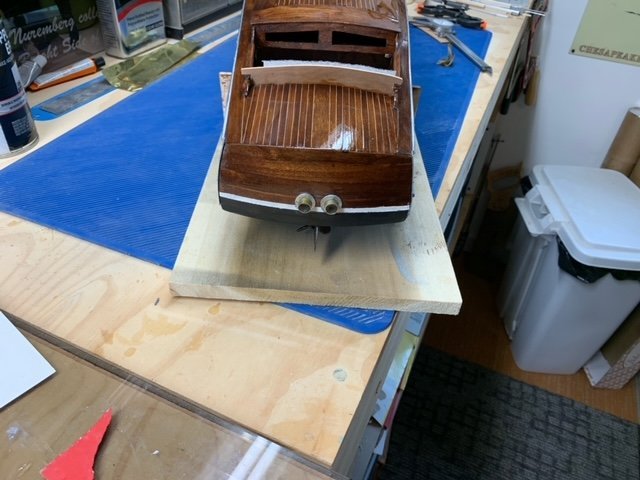
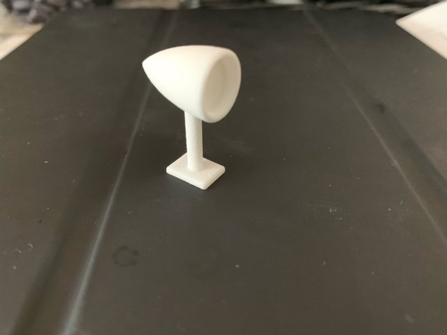
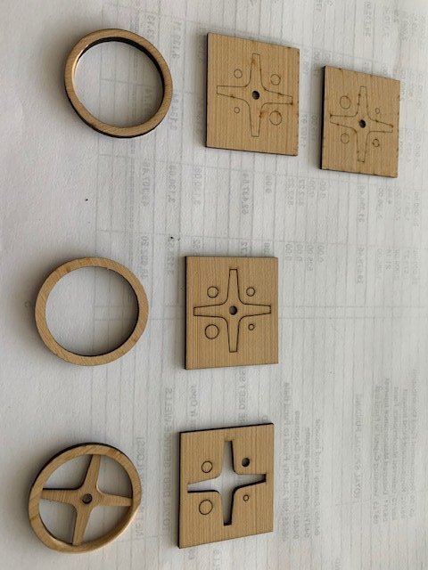
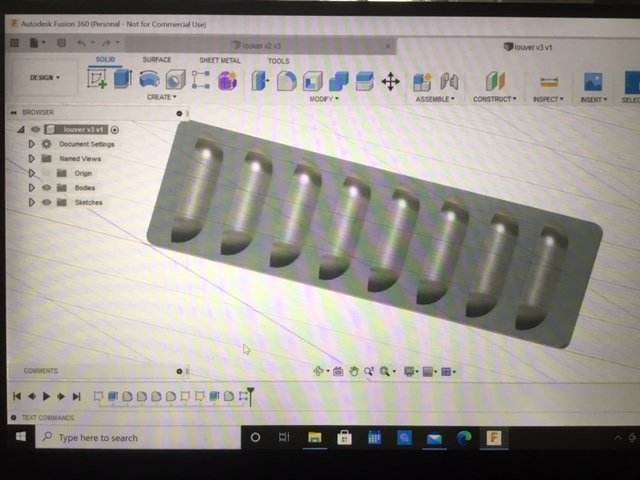
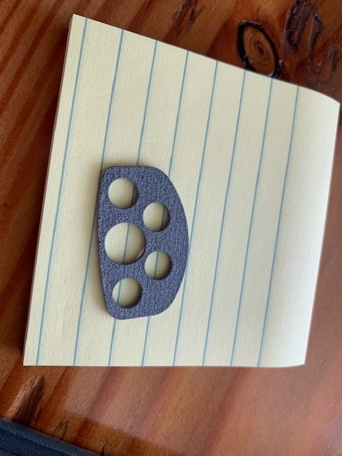
Here is an update on where I am with the Chris Craft Project. At this point, focus has shifted to the fittings and other miscellaneous components of the boat. I had designed, using Fusion 360, and 3D printed, using Shapeways, the gauge panel, as well as the navigation lights, spotlight, and engine louvers. The steering wheel was laser cut by a good friend. Another good friend helped me make the 2 exhaust pipes out of brass tube and wood. Its so nice to have good friends that are much more experienced in modeling then I and I very much appreciative all their help and guidance. I also am using leather for the seat and back coverings. Below are some pictures of various miscellaneous items: Fusion360 Louver Design. Engine gauge and navigation light/ flag holder prior to finishing: Seat covers: Here is a picture of the dash panel showing the steering wheel, ignition switch, and gauges. This picture also shows the engine hatch hinges and brackets added. These are brass strips and rod that are painted chrome. I also added the 2 window supports that allow the window to tilt. Finally in the picture below you can see the engine louvers which as I mentioned were designed using Fusion 360 and 3D printed in this case by a friend. This next picture shows the exhaust pipes at the stern. I painted the flange chrome and left the pipes natural. Although not the best angle, you can partially see the rudder and propeller from this shot. Here is a picture of the raw 3D printed spotlight I designed and got made by Shapeways. There are 2 drawbacks to this route, the first is cost. A typical 3D printed part from Shapeways, of this size and material is ~$5 not including shipping each. This can add up fast. The second issue is texture. The base plastic material is not smooth. I suspect you could choose different material that is smoother but it will certainly cost more. I choose to get it with the standard material and sand it after a primer. This part as with the others shown will be finished with chrome paint. Here is a picture of the laser cut steering wheel prior to shaping and finishing. Thank you Chuck! Next up will be more miscellaneous items such as the railings on the engine deck. The making and installation of the gear shift lever. The making and installation of the windshield and the remaining seat coverings. I also wanted to give a big shout out to gjdale for his recommendation of Callie-Graphics for the boat name graphics. I designed the graphic based on the original photo I had and assumed the color to be a metallic gold with a thin black lining. Callie Graphics was able to take the design and make me a beautiful set of name graphics at a reasonable cost. All for now, stay well! Bill
-
Bill Brown reacted to a post in a topic:
HM Cutter Cheerful 1806 by JpR62 - 1:48 scale
-
Bill Brown reacted to a post in a topic:
1930 26' Chris-Craft Tri-Cockpit Runabout by Bill Brown
-
Thanks Chuck, I will plan to bring it to our September Meeting at the library. Looking forward to finally meeting as a club in person again.
-
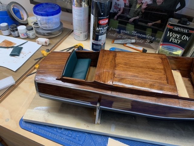
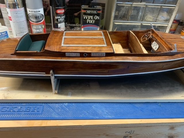
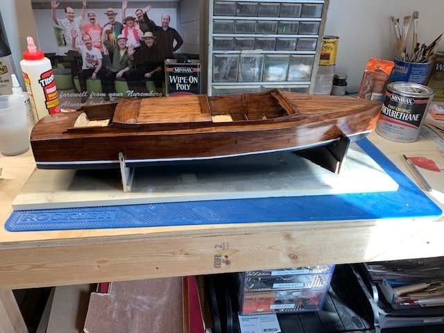
Its been awhile since my last update on Miss Seaside, but I have been working on it as you will see below. Picking up from where I left off, the next step was to build the cockpit seats. The following photos show this for the stern cockpit seat as well as the mid cockpit seat. These will later get some cushions added to complete the seats but I am holding off on this to protect them as much as possible during the build process. For finishing, I choose a red mahogany stain with several layers of a gloss polyurethane over top. This was sanded after each coat 120grit - 180 - 220 - 400 - 800 - 1500. I also used a flat black bottom paint for below the waterline with a white accent painted strip at the waterline. A preliminary view of this is shown below: I used chrome spray painted brass strips for some of the accent pieces as well as chrome painted semi round polystyrene strips for the rub rails. These can be seen in the photo below: In the above photo you can see the dash installed. In my next installment I will show some details of its construction. I used some 3D printed parts that I designed using Fusion 360 and fabricated at Shapeways Inc. Until then, be well! Bill
-
Thanks for the comment Mike and to answer your question, since this was to be only a static model for display I choose the lift method as the easiest and quickest way to get a hull with the limited plans I had from the Mariners Museum. In addition, with the lift method I found the cherry planking for both the hull and deck was much easier to install in my opinion. I did use polystyrene strips for the caulking as well as for the rub rails. In the case of the rails the strips got sprayed with a metallic chrome paint after getting drilled for pins. I followed your log and your models of this genre are beautiful. I am currently trying to secure some boat name decals from the place on eBay you suggested.
-
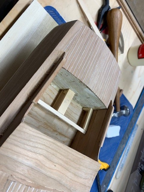
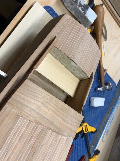
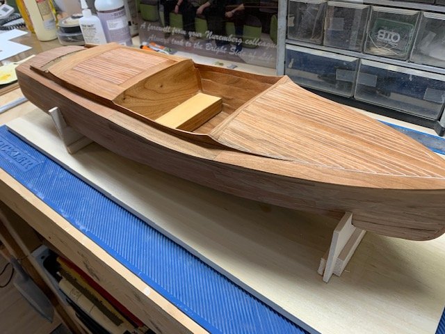
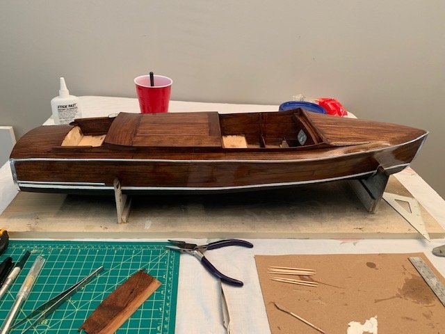
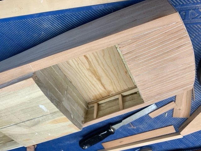
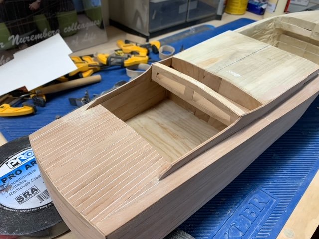
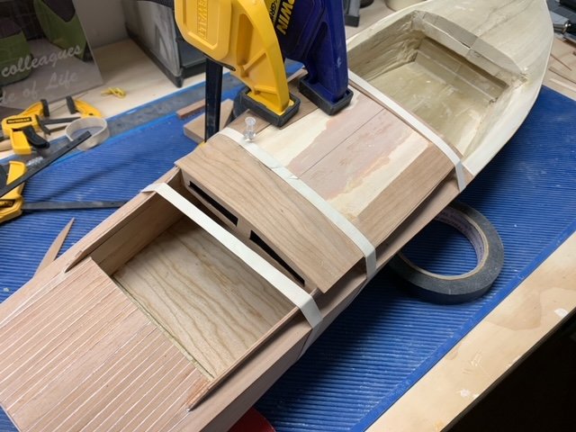
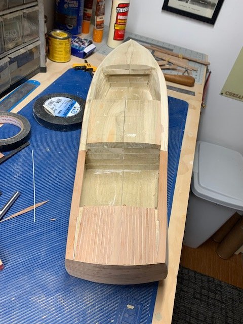
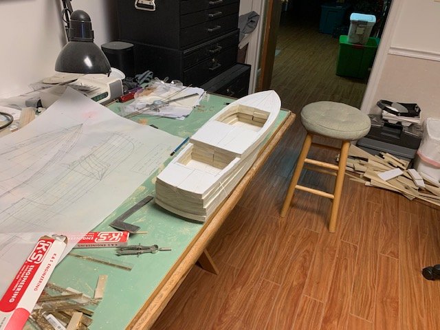
Well its been more than a month since my last update but I have been busy on the project. I continue to work from stern to bow with planking and structural details. In the photo above I have completed the interior cockpit planking and have started on the aft engine storage compartment. This area is one of the key differences between the 24 and 26 footer. My attention then turned to the engine deck area. The boat is designed with two hatches that open in the center. I will create the hinges and handles at a later time. After finishing the engine hatch planking. I then moved to the forward cockpit area where I proceeded to plank the interior bulkheads in a similar manner to the aft cockpit. Having completed the interior planking in the forward cockpit I then tackled the dash. Finally with the dash in place I was now able to focus on the bow deck which would prove to be the most challenging to date. The bow has a beam to beam camber as well as a slope from dash to bow. In the photo below I tried to simulate the curvature of the bow as best I could with the limited plan information I have. This required some filler wood and Bondo. I ended up having to do this twice as I was not happy the way iteration 1 turned out at all. The picture below shows the deck as it stands right now. This is iteration 2. The boat has a square access hatch located in the middle of the deck that will need to get added at a later time. I am also not happy with the interior cockpit planking as I should have added more frames to the back side. The planking I am working with is only 1/32" thick so not a lot of room for error. And error I do have. So the next step will be to replace the interior planking only after I beef up the frame support. Ugh. Its definitely a 2 step forward 1 step back kind of project so far. Oh well it is what is. Once I get the interior planking sorted out my attention will turn to final sanding and finishing of the hull and deck. The boat will get bottom paint. Flat black below the waterline. It will also receive a decorative white stripe just above the waterline. I plan to finish the rest of the wood with a red mahogany stain topped with several coats of gloss poly, sanding in-between coats. One thing I have to decide is if I stain the narrow deck planks with a lighter stain. I have seen this on some real-life full scale restorations and its sharp. I am just not sure that would represent the Miss Seaside that I am attempting to model. All I have is a black and white photograph and there does not appear to be a tone difference between the top side and deck planks. Once the finish is applied my attention will turn to the interior (seats, cushions, gauges) and exterior/interior metal trim details. Until then, be well. Bill
.jpeg.75d3ea174605cfd790951e2e81eb5bc6.jpeg)
-
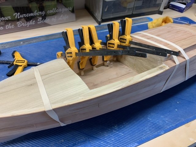
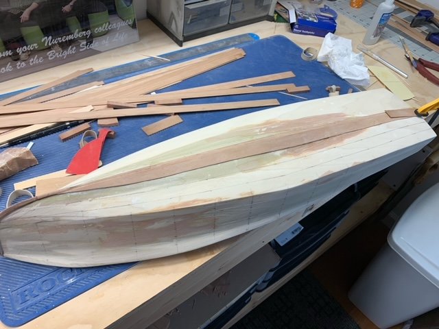
It's been about a month since my last post and I have made some more progress on the Chris that I would like to share. When I last left off I had just finished planking the hull below the Chine. I am still not sure whether I will leave this part of the hull bottom natural (mahogany stain and poly) or apply a bottom paint (black or green). It will get a white accent strip added just above the water line either way. My attention now turned to planking the sides between the Sheer and Chine. As with the bottom of the hull, I will be using 1/32" thick cherry planks. From full size project boats listed on the internet, I was able to determine the number of planks between the Sheer and Chine to be 6. This allowed me to create tick strips for each hull station and mark the plank widths at each location. I made templates for each plank and then used my Burns Saw and Dremel Belt Sander to create the individual planks. These were affixed to the poplar base using PVA glue. For clamps I used a combination of bar clamps, rubber bands, and push pins. Its a slow process but also a straight forward one. I used this same process to plank the stern having determined the plank number from another full size project boat for sale on the internet. Eventually I was able to complete all the hull planks with the cherry veneer. My attention now turned to the deck where I will work from stern to bow. These boats had beautiful decking using a combination of mahogany planks and lighter caulking. I will continue with the cherry for the deck planks and use a poly styrene (0.01x0.03") strip in-between the planks. I was able to determine from actual boat pictures, the number of deck planks across the stern. Knowing this allowed me to determine the deck plank widths, in my case 0.15". A wider center plank is added first to the stern deck and then working from the center out to the sides I added the planks and styrene strips. This is about as far as I got this month. Next time hopefully I can show the aft cockpit being worked on as well as decking the engine deck. This deck area flares up as it flows to the stern and also has 2 doors for engine access. This will be more challenging then the stern. Until then, hope everyone is staying safe and healthy! Bill
-
You do such beautiful work Ken. Outstanding craftsmanship! Looking forward to seeing this in person at some point soon I hope. Bill
- 238 replies
-
- 4
-
-
- sloop
- providence
- (and 1 more)
-
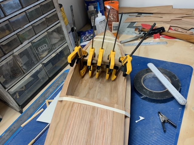
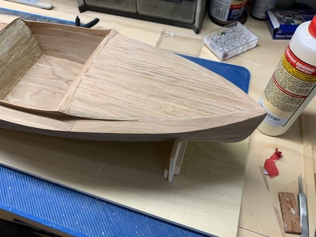
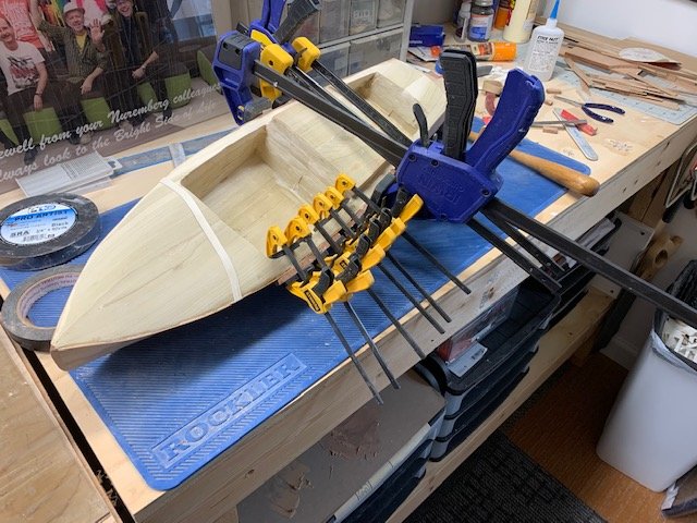
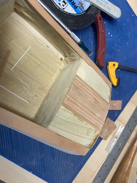
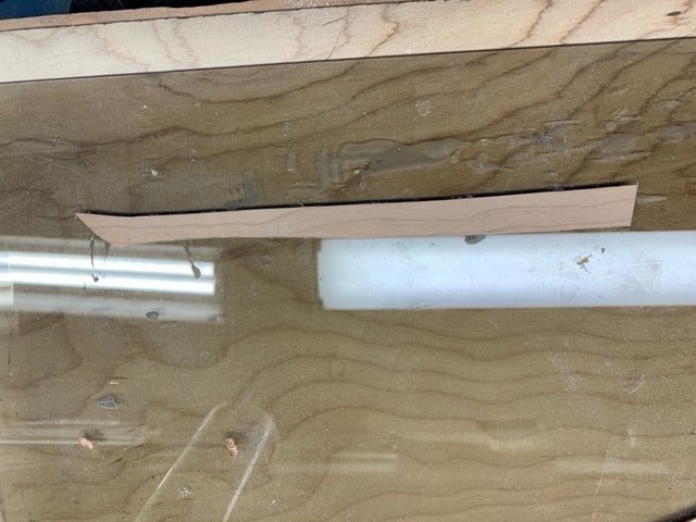
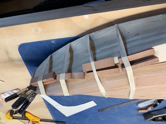
With the hull shaped to the station profiles and the chine marked, I turned my attention to the stem and keel. The stem and keel will be solid cherry and I will simulate the keel along the length with a narrow cherry plank. I want these solid cherry pieces to also provide a rabbit for the planking. In the picture below you can see both the keel and stem glued to the poplar hull. The picture also shows that I have lined the hull. I was able to decipher from a picture on the internet, of an actual 26 footer, that there were 3 planks between the chine and keel at the bow and this increased to 4 as it worked back to the stern. With this information I could draw out the planks and start the planking process. In the picture above the garboard plank is secured on the starboard side of the hull. Given the width of planks I was dealing with, edge bending seemed impractical (for me at least). Instead I opted to trace the plank profiles using tracing paper and then use it in conjunction with some heavy bond paper cut out to shape and used as templates. In doing this, you got some unique shapes as shown in the photo below: For clamping I used some thick rubber bands along with some sacrificial cherry blocks to supplement my normal clamping tools. So with much patience, that I lack by the way, I slowly installed all the planks between the chine and keel/stem. Its a slow process but I am pleased with the outcome so far. Here is a photo of the completed planking below the chine. I used Titebond PVA for gluing. The next steps will be to tackle the rest of the planking between the chine and sheer. This will prove to be slightly more challenging as this region requires more plank curvature. Cherry is such a beautiful wood.. All for now, until next time be well and happy modeling! Bill
-
You might consider joining a ship model club. I am with the Ship Model Society of New Jersey and we are always looking for new members. We have folks in our club from Brooklyn, Staten Island, and even Weschester and Rockland. But there are other clubs as well. We meet at the Roseland Library right off Rt 280 but lately we have been meeting virtually and would like to continue with that capability even after we can meet again in person. If you are interested, PM me and I will make sure you get an invite to our next virtual meeting which will be the 4th Tuesday in February. Bill SMSNJ
-
Welcome Michael, I just sent you a link to tonight’s Ship Model Society of New Jersey January meeting. I hope you can attend. I also built the Eastport Pinky known as the Yankee Hero. It was a great kit and I enjoyed the build very much. I look forward to your build log and also hope you will consider joining our club. Bill SMSNJ
-
Thanks Grant. No I hadn’t as this particular model is destined for a local town museum. The town wanted a static model of a boat that had some historical significance to them. The Miss Seaside used to give speedboat rides to visiting tourists. I can also tell you that using this build method, it’s heavy! I will say that an RC version of this design would be awesome!
-
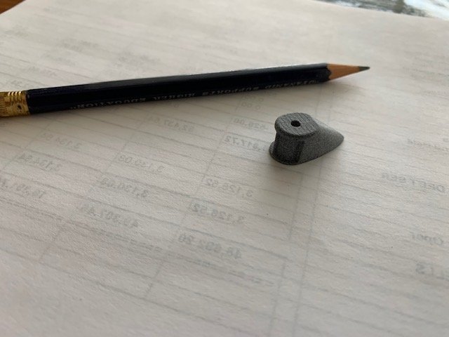
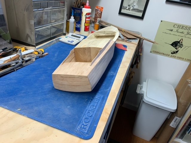
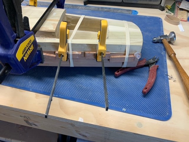
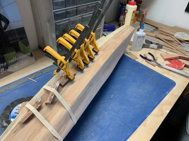
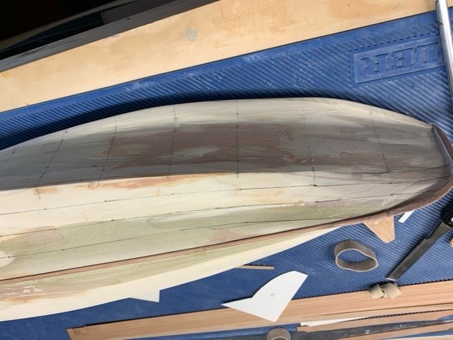
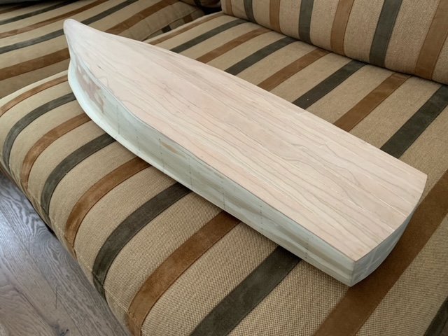
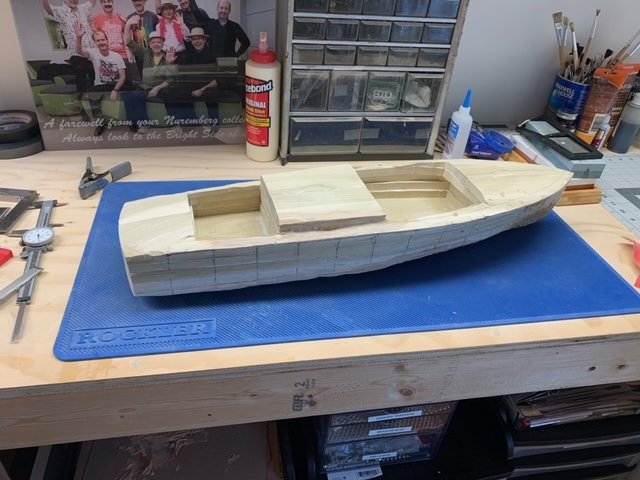
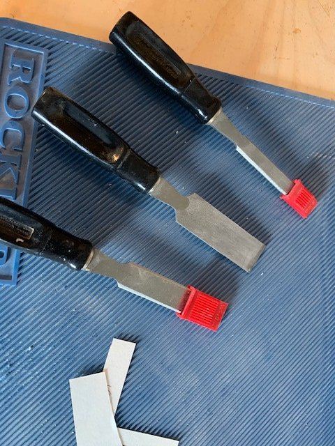
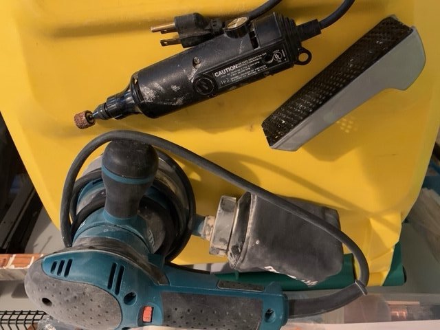
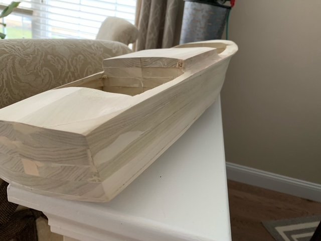
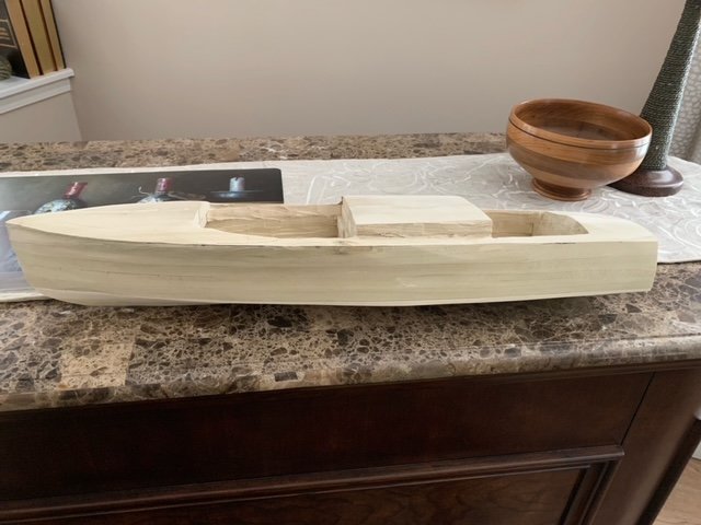
I got some great help from a fellow club member and a great friend. In his shop he has some very nice tools including a beautiful scroll saw and an oscillating spindle sander that made cutting out the qty 8, 1/2" lifts straight forward. Along with cutting out the waterlines for all 8 pieces, care needs to be taken to mark all 13 stations on each lift as well as the centerline for the full beam boards. These will be used to align the lifts for gluing. Below is a picture of the 8 lifts stacked: She is already starting to look like a boat! Once all the lifts are cut and sanded to the waterline marks, its time to glue them all together. I used PVA glue and glued the lifts one at a time. This proved to be challenging as its tough to keep everything in exact alignment while clamping the lifts together. Here is a photo of the lifts all glued together with some rough shaping already accomplished. For someone who just finished building the POB model of the HMS Cheerful, the toolset for this project is a little different. The best tool to start the shaping process is the chisel. Here are the set I used: Make sure they are sharp. I can't emphasize this enough! We had an excellent tech session at one of our club meetings demonstrating the proper way to sharpen a chisel using a whet stone. Thank you Eric! You are going to create a lot of poplar wood chips. Once you have the macro shaping complete its time to switch to the rasp and then the sanders. Again this is still at the macro level of material removal. Unlike my last project, here are some of the tools used for this process: Care must be taken in using tools like these as a lot of material can be removed in a short period of time. Sometimes more material than you want ; ) I did invest in a pint of Bondo Wood Filler. The entire hull will be planked over with Cherry Veneer so I am not concerned if I have a filled hole here or there. The important thing is that the hull flows smoothly according to the plans. Prior to doing this it is extremely important to mark both the Sheer and the Chine at all stations. You also want to use your station profiles frequently as you get close to the desired contours of the hull. You will have to repeatedly mark the stations during this process as the sanding operation will remove your previous lines. Here is the hull with macro material removal complete. Each station fits the profiles well at this stage but it still needs a lot of fine tuning before I can say it is ready to be planked. So I will leave it here for now. Next steps are to perform the finer sanding and shaping to make sure there are no high or low spots and the lines flow evenly. Its amazing to me how fast you can get a reasonable hull by using the lift method. Until next time be well... Bill
-
Thanks Mike! Miss seeing you guys. Looking forward to being able to get back together this year. Meddo, thanks for the kind words. You will enjoy this project. It is well engineered. I look forward to following your build log.
- 54 replies
-
- 2
-
-
- cheerful
- Syren Ship Model Company
- (and 1 more)