shipmodel
-
Posts
941 -
Joined
-
Last visited
Content Type
Profiles
Forums
Gallery
Events
Everything posted by shipmodel
-
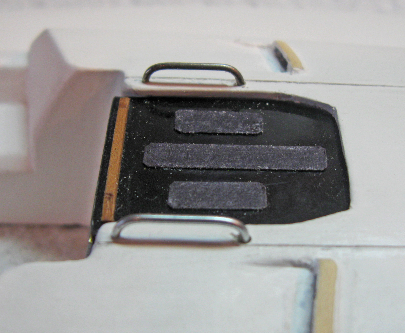
 No, the sandpaper was thin enough but it was too grey and stood out from the black of the hatch, which does not happen on the boat. The non-skid areas of the cabin roof and deck are lighter than the sandpaper, so I am still experimenting. It has to mold to compound curves without a seam or wrinkle. The leading candidate is a heavy tissue paper that is misted with water. I've been looking for silkspan, but haven't found any in my art supply store. Dan
 -
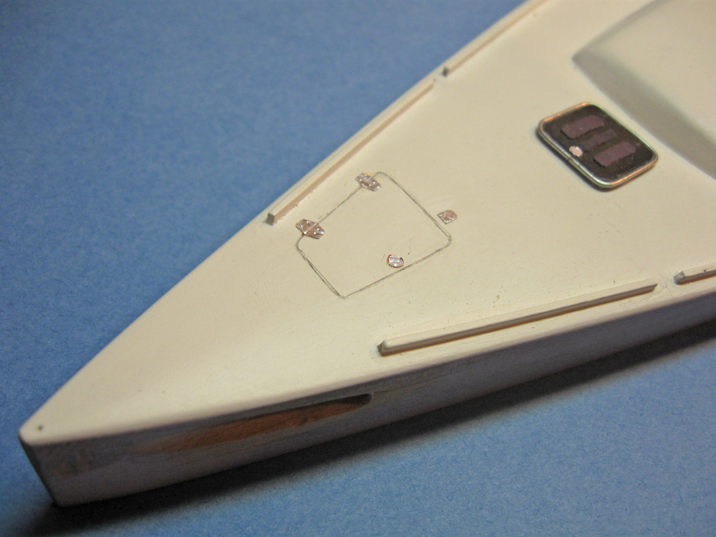
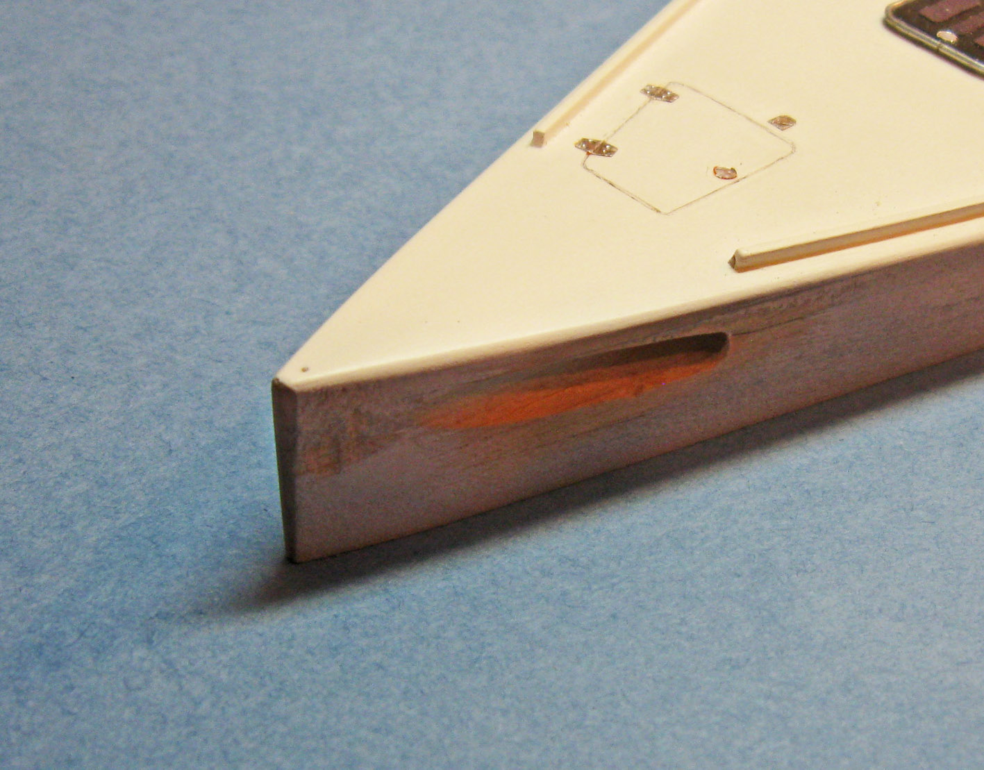
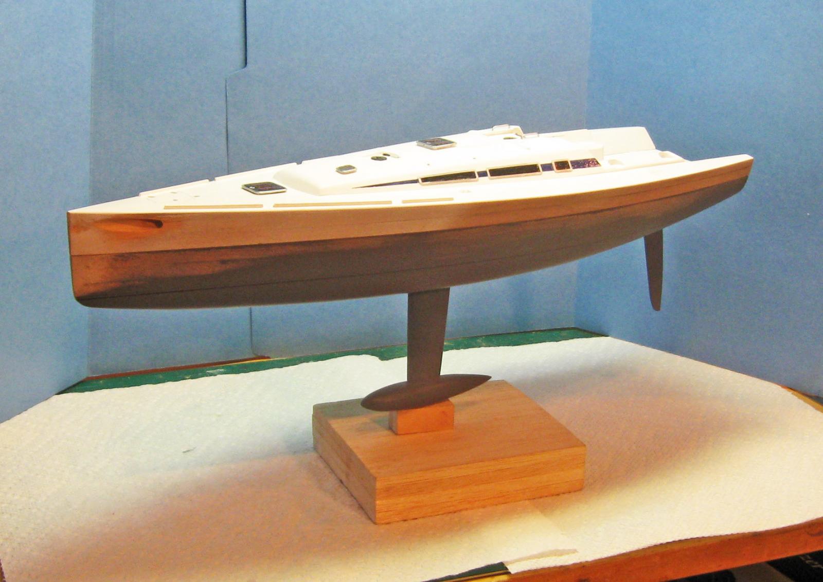
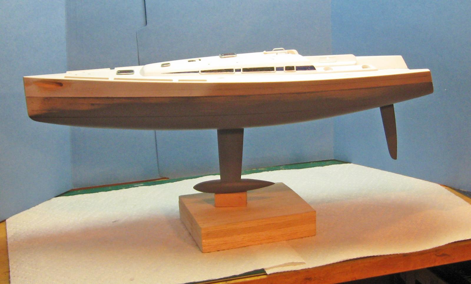
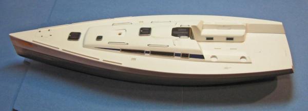
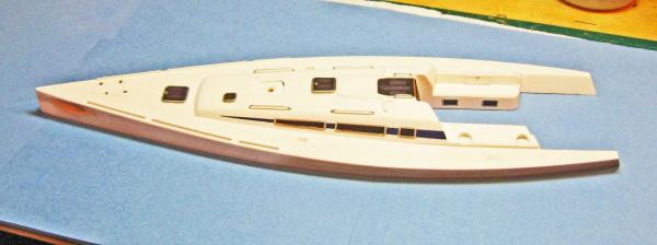
Hi again - Progress since my last posting includes the cabin roof handholds formed and electroplated, the several raised and flush hatches, cabin and cockpit windows, and the socket for the spinnaker pole. I just bit the bullet and glued the upper hull to the lower, which is curing as I write this. Now I can sand the hull to final shape and smoothness, then paint it with gloss blue. Look for it next time. Here is the overall upper hull. The cabin windows were masked and the tapered streak hand painted with the gloss blue lacquer decanted from the spray can. The window frames are built up from 0.010" x 0.030" plastic strip. The corners are chamfered and they are painted a metallic silver. On the boat they have a satin finish, which the paint replicates quite well. The windows themselves are gloss black paint, since they are set flush with the surface of the cabin and plastic sheet could not be inset. The cockpit windows are built up in a similar fashion. The hatch in the seat back is built up from unpainted strip with the 1/16" latch punched out from a chrome plated foil sheet. At the bow is a trapezoidal hatch set flush into the deck. The size and shape were taken from the plans, a template made from shim brass, then scribed around. The hinges, latch, and lock were cut from the chrome foil. There are several raised hatches with coamings on the cabin roof and forward deck. These were built up from three layers of plastic, the top one being clear with black paint on the reverse side. The chrome edging is brass rod bent and fitted to the hatch, then electroplated and glued in place. Like the companionway hatch, the non-skid areas are art paper appliques. The lock is chrome foil. There will be two grey plastic latches fitted as well. The first set of these did not make the cut. The last piece of major machining for the upper hull was the socket for the spinnaker pole on the port side. The pole slides into the hull when not in use, and then slides out at an angle so the forward end lies on the centerline of the boat. This was carefully drilled with an undersized bitt, then slowly and carefully expanded to final size and angle. As you can imagine, this was High Anxiety without Mel Brooks' humor to lighten the mood. One slip and I might be forced to discard the entire upper hull. Fortunately, it came out well, but will be further refined once the hull pieces are joined. Before the upper and lower hull pieces were joined a perimeter trench was routed and chiseled into the lower hull to give any wood movement in the lifts a place to go other than outward to crack the surface of the model. Here are the two hull sections joined together. I use a conservator's neutral pH PVA glue from Lineco. I find that it cures faster than the usual white glues and seems a bit stronger as well. And here are all the pieces mounted on the stand, including the rudder which was machined from 1/8" basswood sheet and secured with a brass rod into a socket in the hull. The rudder and keel are still removable and will remain so until almost the final moments of construction so they do not get damaged by my clumsy handling. Till next time - be well. Dan


-
The more I looked at the last photo the more the handholds looked like steel, not chrome. Replating over the last layer, with polishing with a soft fabric wheel made a big difference. Compare the new starboard handhold to the old port one. Now I think I nailed it. Dan
-
Here's the replacement pair. OD down from 0.045" to 0.030". Better?
-
David, Tom - That was my thought too. You pushed me past the tipping point and the handholds will be replaced. The lines that are in the jam cleats (is that the proper term? I have been calling them line brakes) are just to hold the place and as leaders when the actual lines are run. They are much smaller than the working lines will be. Compare them to those in the photos of the actual boats. Thanks Dan
-
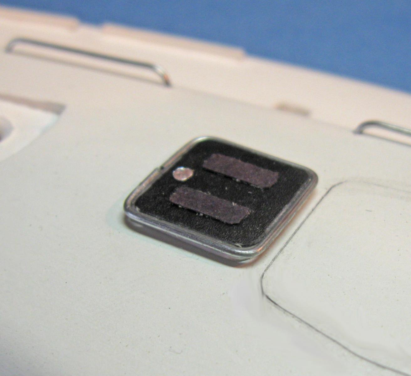
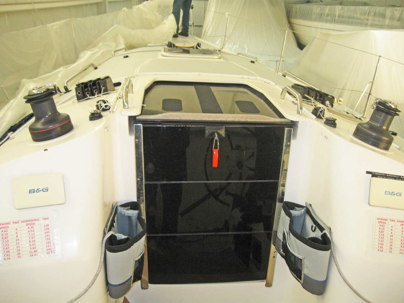
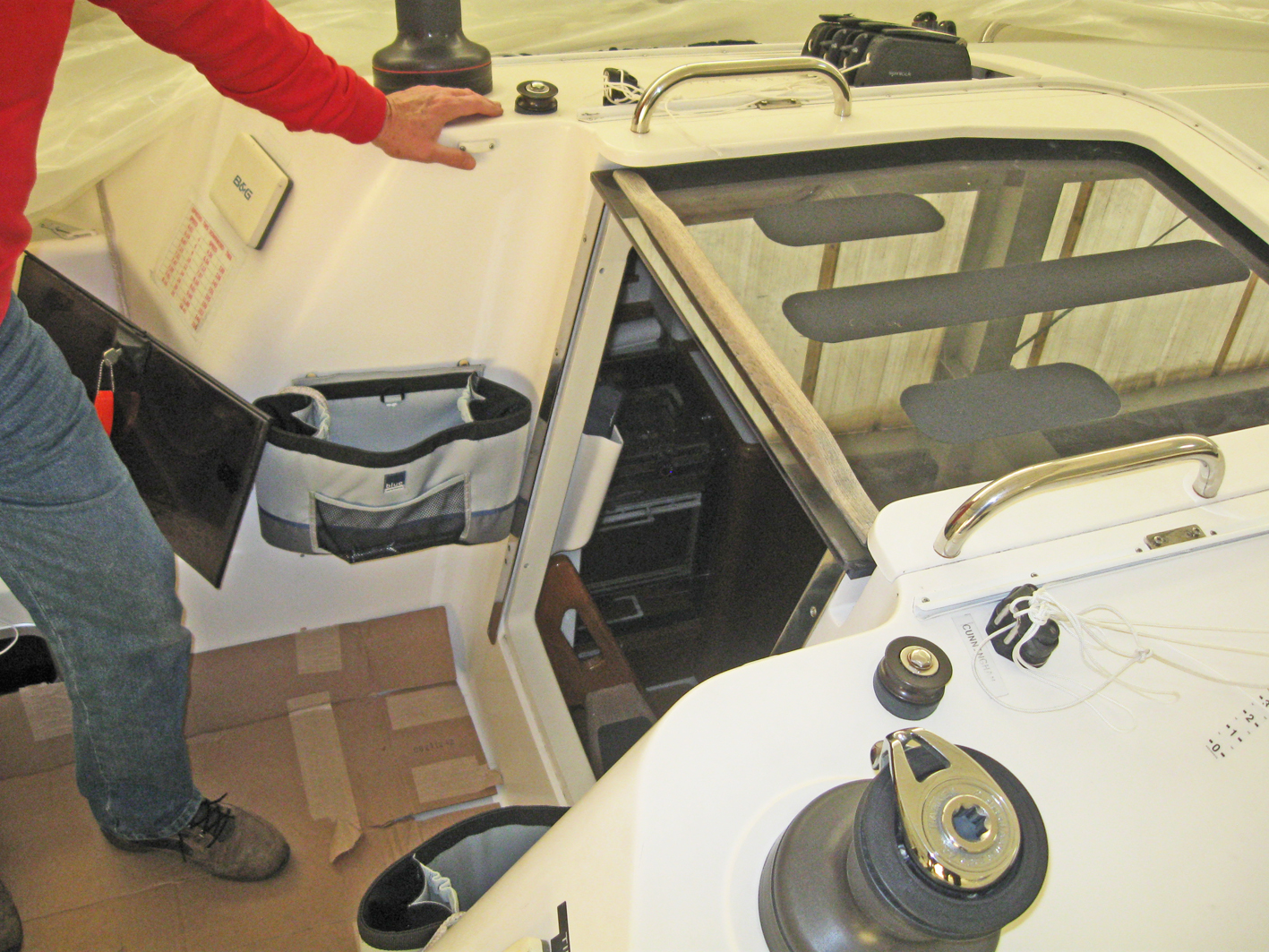
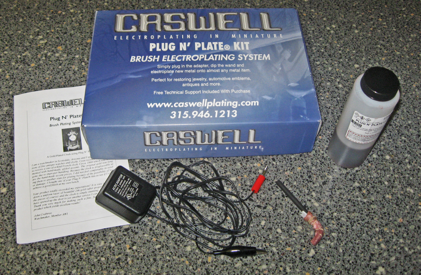
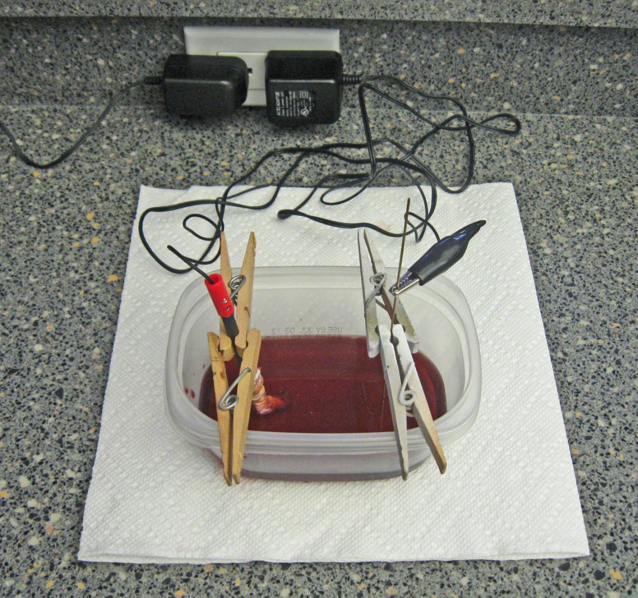
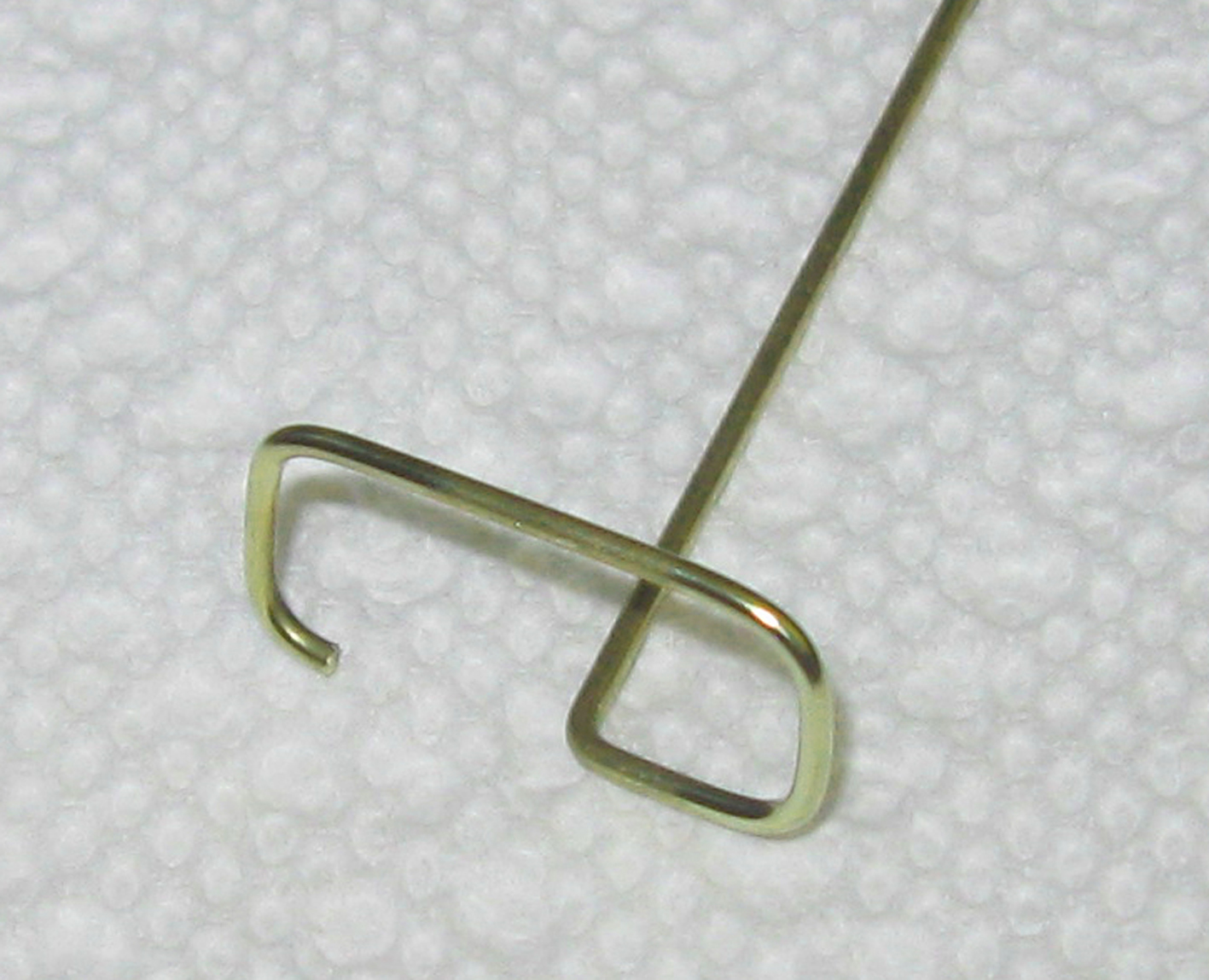
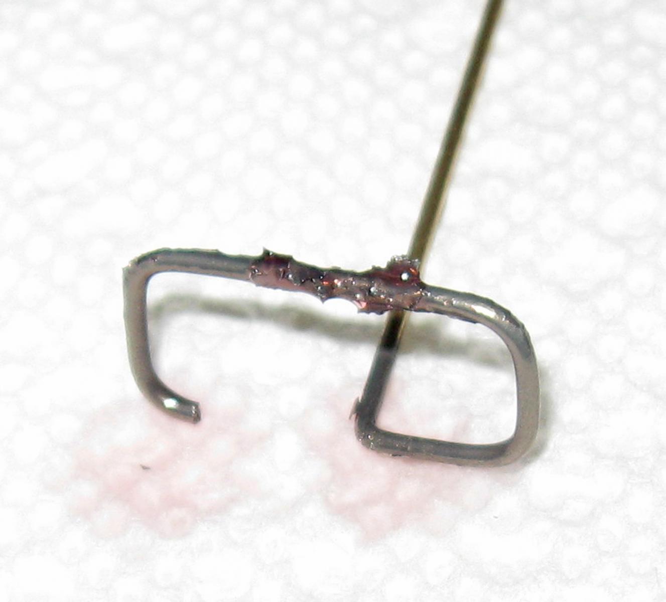
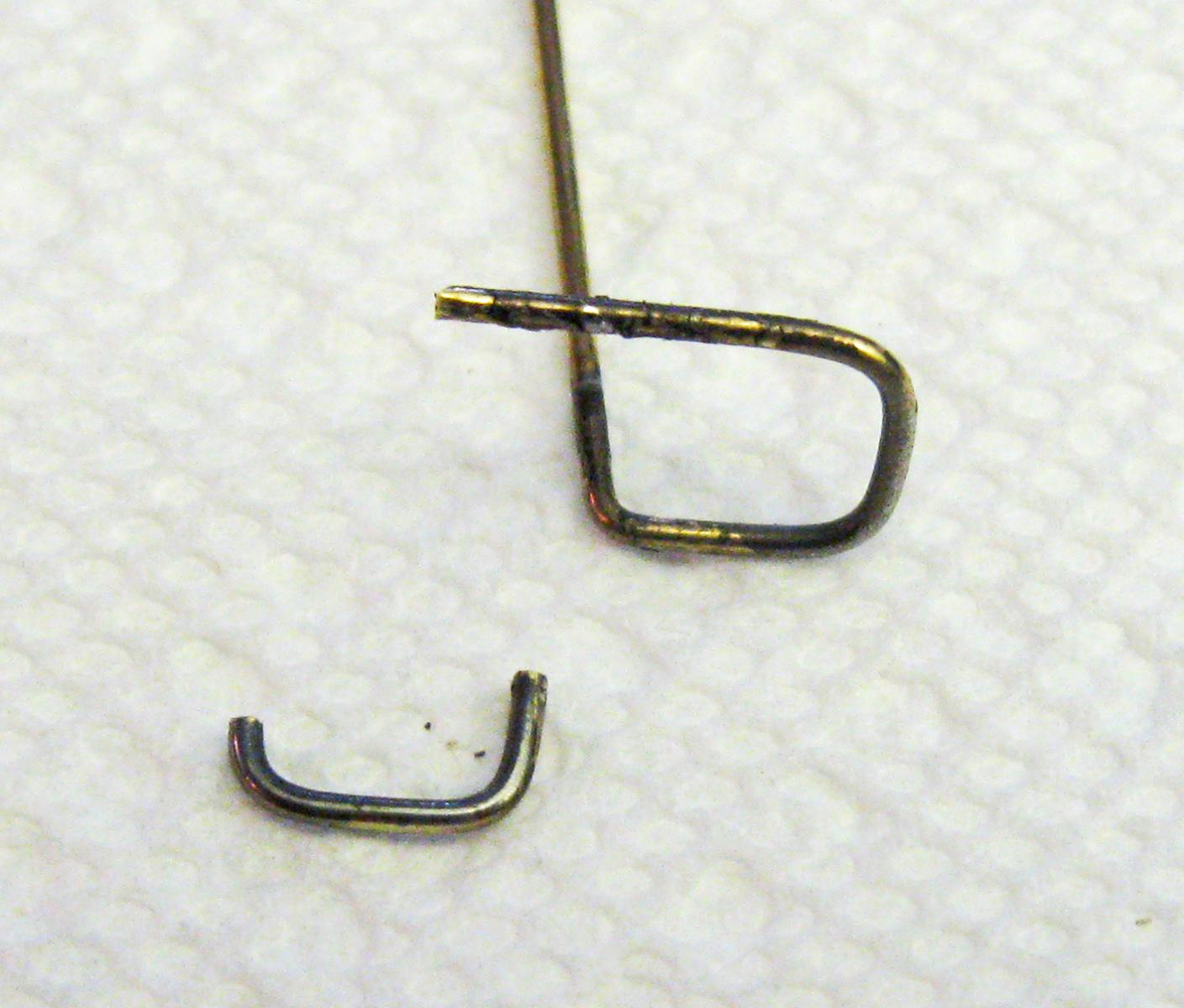
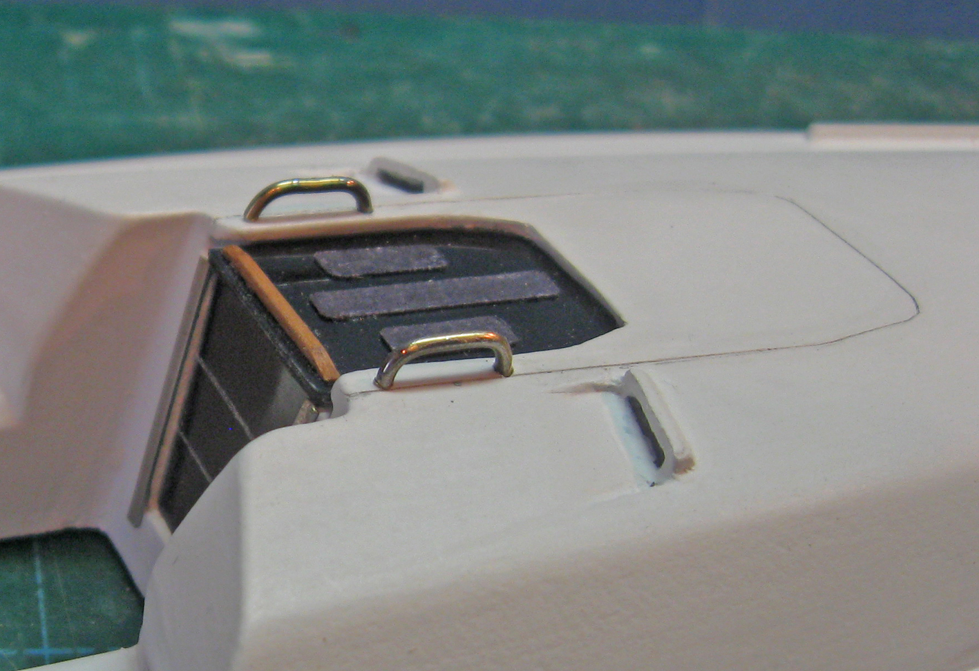
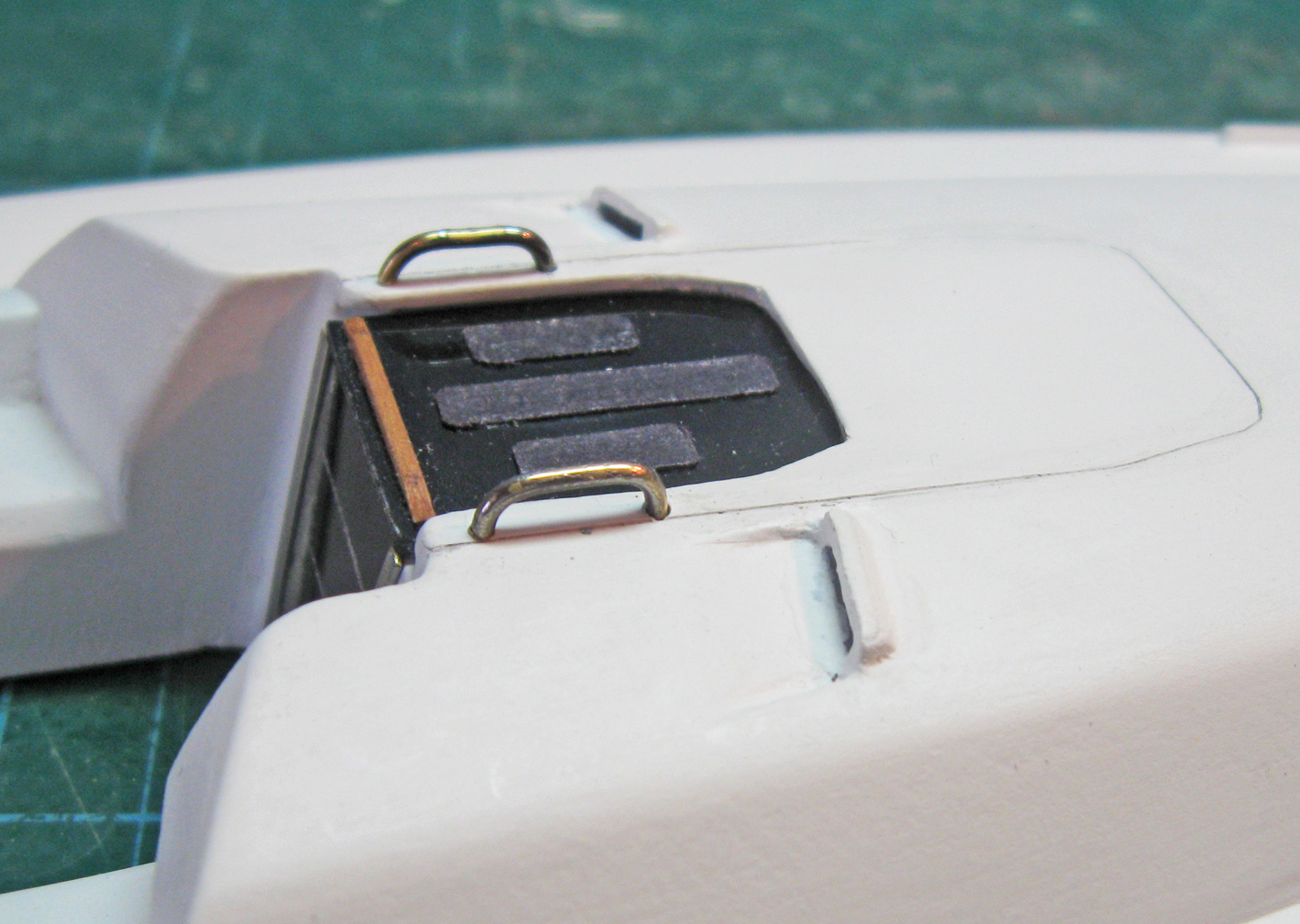
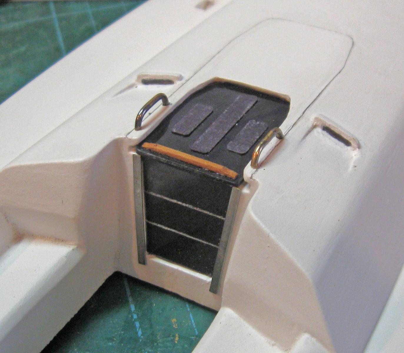
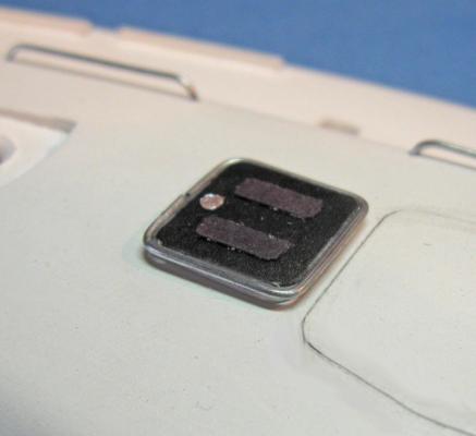
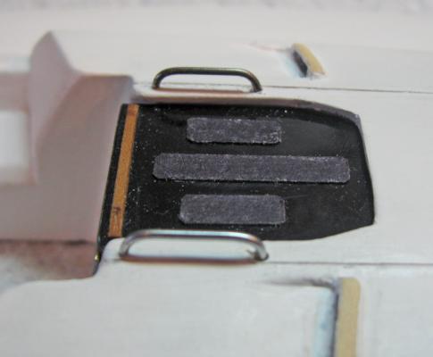
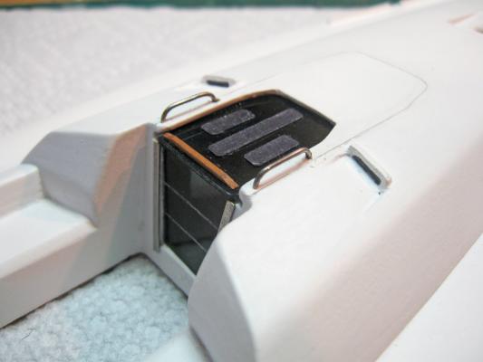
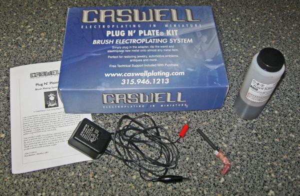
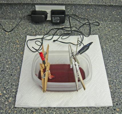
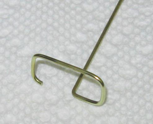
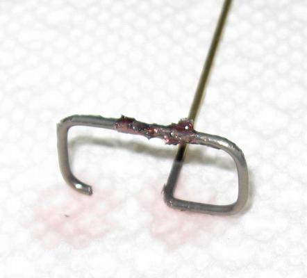
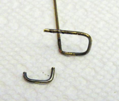
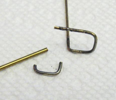
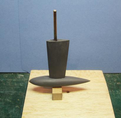
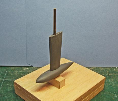
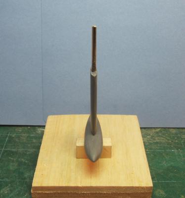
Hi all - Thanks for the compliments. I hope that you will continue to enjoy the journey as I work my way up the learning curve for a model like this one. This post takes me to the companionway and its various components and materials. Here is what it looks like. The vertical side is composed of three plexiglass panels of diminishing size. They slide down in a channel behind the chrome strips to either side The top is one panel with a teak handle and three non-slip areas etched into it. It slides into the channel under the roof. To either side are chrome handholds next to the line brake ramps. Here is my completed companionway. The panels are clear plastic with the reverse painted flat black. The panel lines are scribed, the anti-skid areas are paper appliques. The retaining strips and handholds are chrome plated brass. Almost nothing is permanently mounted at this point, since I may want to remove them and replace them with better efforts. Most of the time since my last post has been taken up with learning how to electroplate. Here is the kit from Caswell that I used. It should be perfect for the amount of electroplating that I will be doing on this model. There are only three components - the plating wand with its fabric cover, the chrome plating solution, and the power supply. In this setup I am not using the wand as a brush, but as an electrode dipped into a plastic container of the solution. The other electrode is clipped to a brass piece to be plated. The clothes pins support both and keep them off the floor of the container. Once this is set up, the power supply is plugged in and the plating begins. It is no more difficult than that. Here is the process for plating some brass rod to make the handholds. First the rod is bent to the shape that I wanted. Both handholds will be cut from this one piece. The rod is polished with a wire wheel in the Dremel, and not touched after polishing. Here it is after 5 minutes of plating. There is some buildup on one section of the rod, but that piece will not be used. Now the rod is polished with the wire wheel and the handhold section cut off. I leave one leg longer to be inserted in a hole in the model. The other end will simply rest on the surface. This make it very easy to install, without worrying about getting two holes spaced perfectly, but still gives a positive mechanical connection for the piece. For contrast, here is the plated handhold with an unplated brass rod. The difference is clear. And, again, here are the handholds temporarily installed on the model. With this magnification I can see that there has to be a bit more cleanup on the line brake ramps and tunnels. But I am closing in on 'acceptable' and working my way up to 'good.' Comments and suggestions always welcome. It is much easier to change things now, and many eyes are always better than one somewhat biased pair. Dan


-
ROYAL CAROLINE 1749 by Doris - 1:40 - CARD
shipmodel replied to DORIS's topic in - Build logs for subjects built 1501 - 1750
Hi Doris - Your talent and artistry leave me breathless. The crowns, the carvings, the figures set a standard that I doubt that I will ever reach. Wonderful use of color and texture. I will continue to be a devoted follower of your build. Thank you for sharing. I have one suggestion, if I may - the pumps as drawn on the plans would interfere with both the cabin doors and the stairways, once you install them. You might consider rotating them 45 degrees forward, which was not uncommon in the era. This clears both access paths and also gives the sailor working the pump a larger space, possibly enough for two men on the handle at one time if needed. I may be wrong, so feel free to ignore this idea. Dan- 883 replies
-
- 1
-

-
- royal caroline
- ship of the line
- (and 1 more)
-
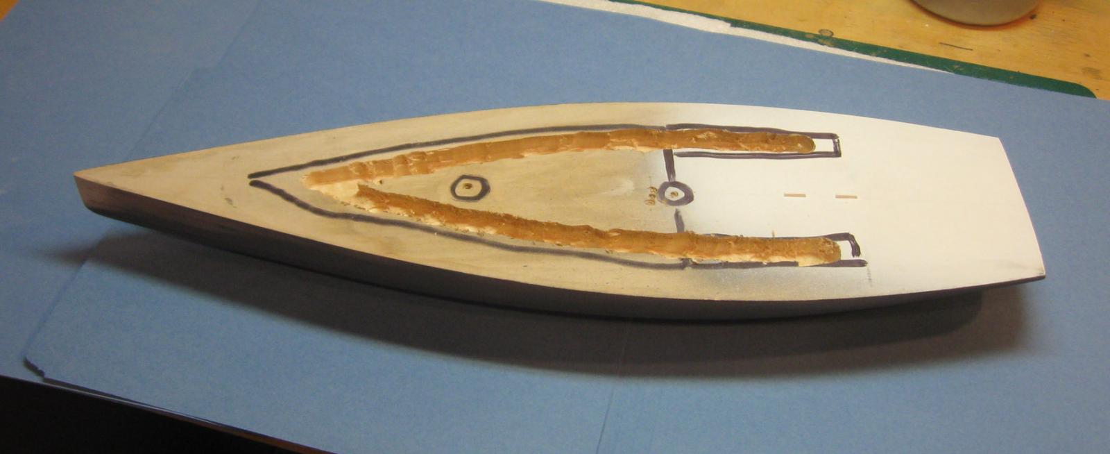
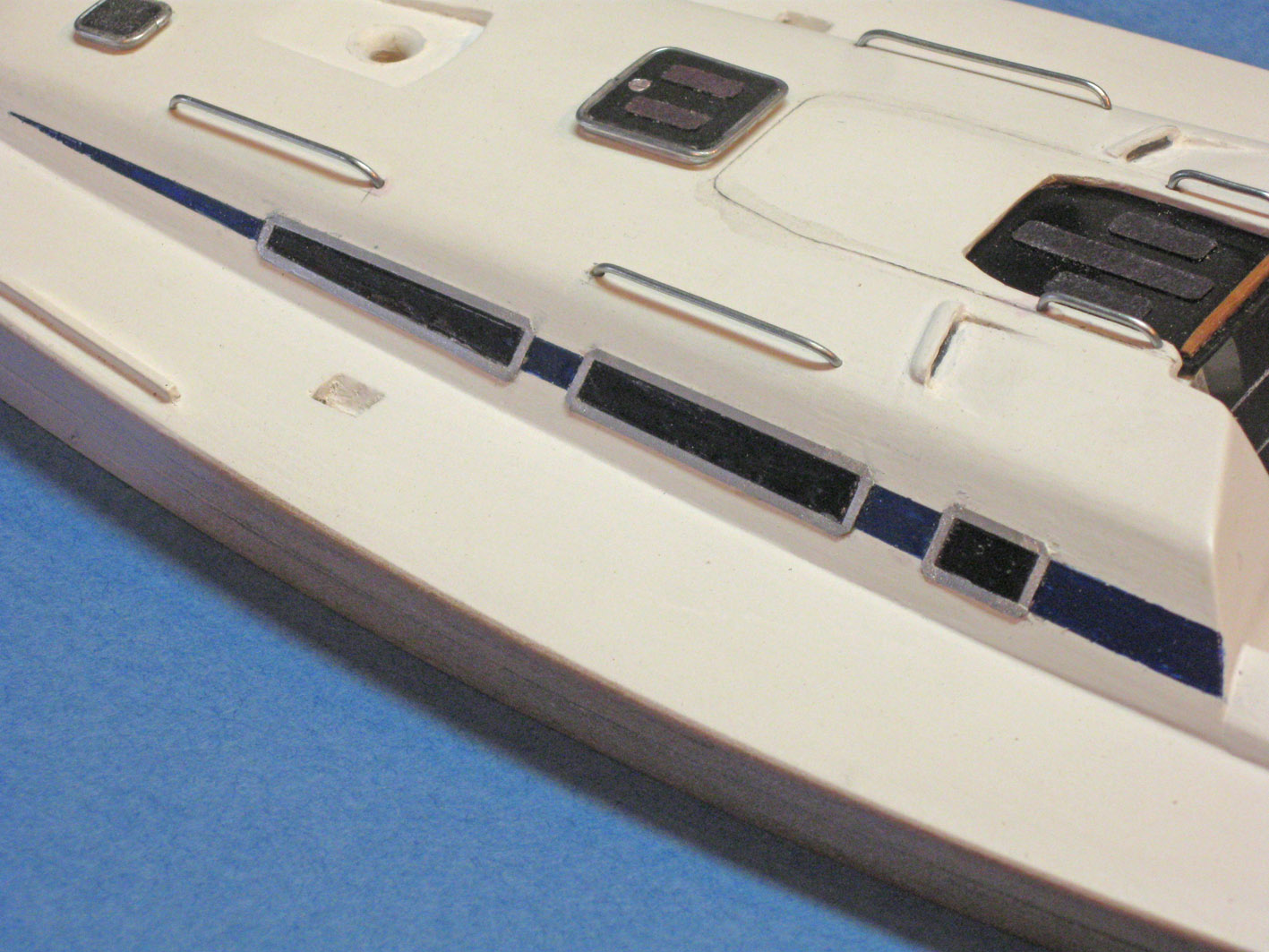
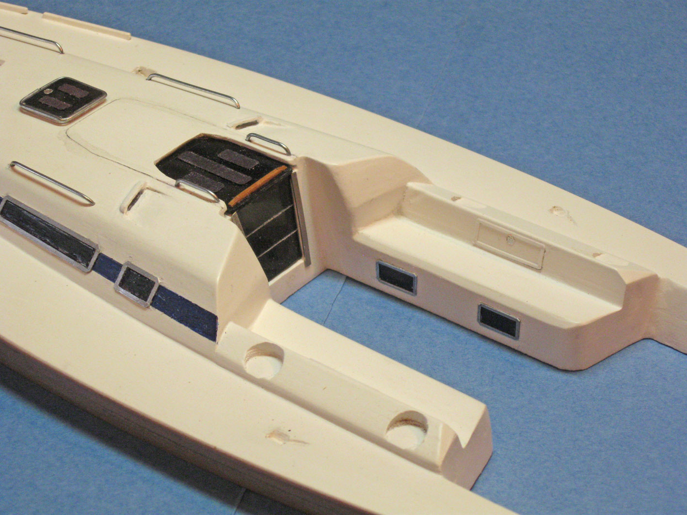
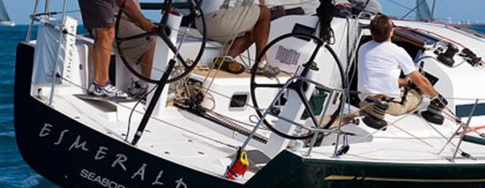
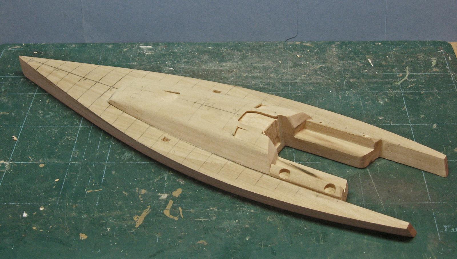
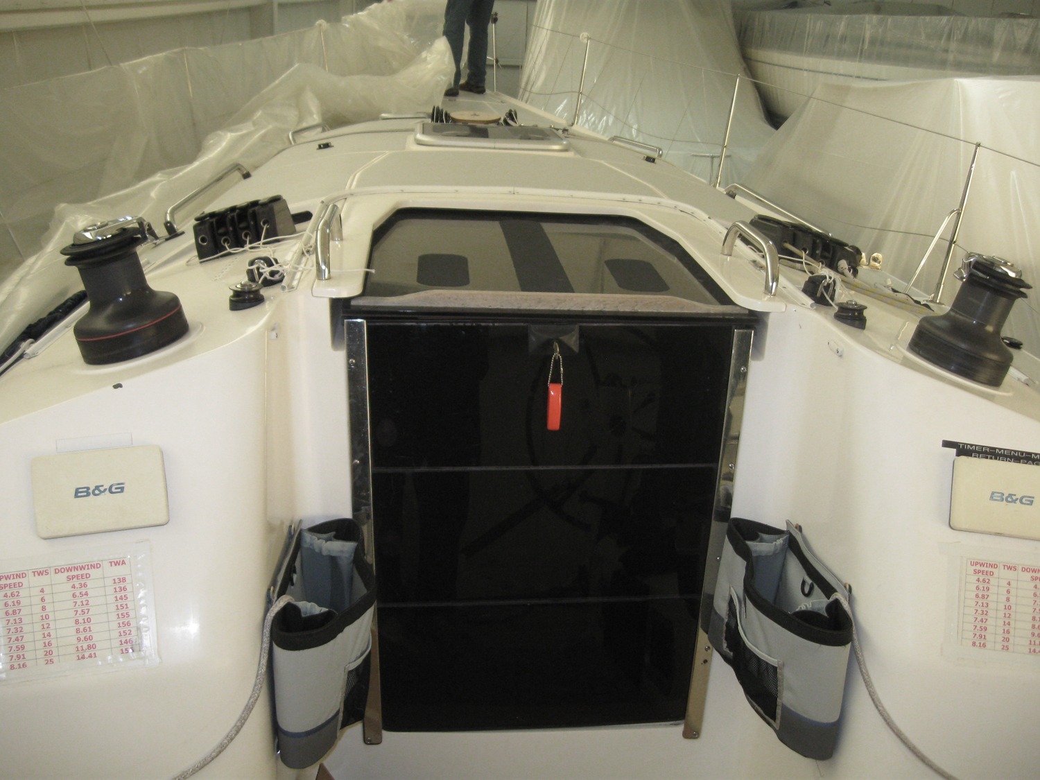
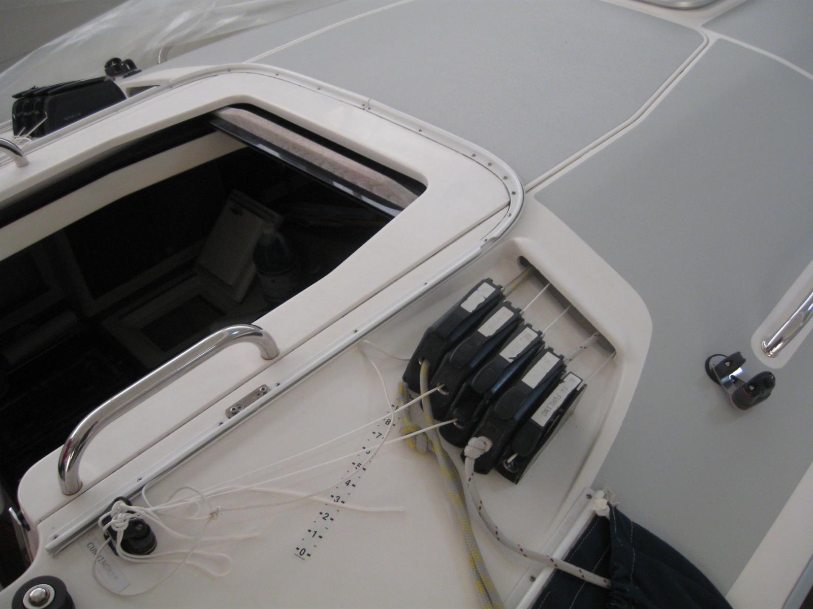
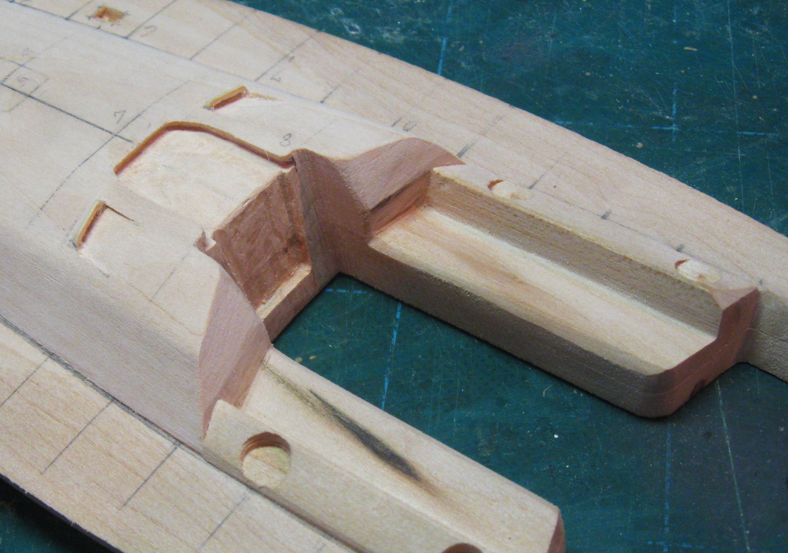
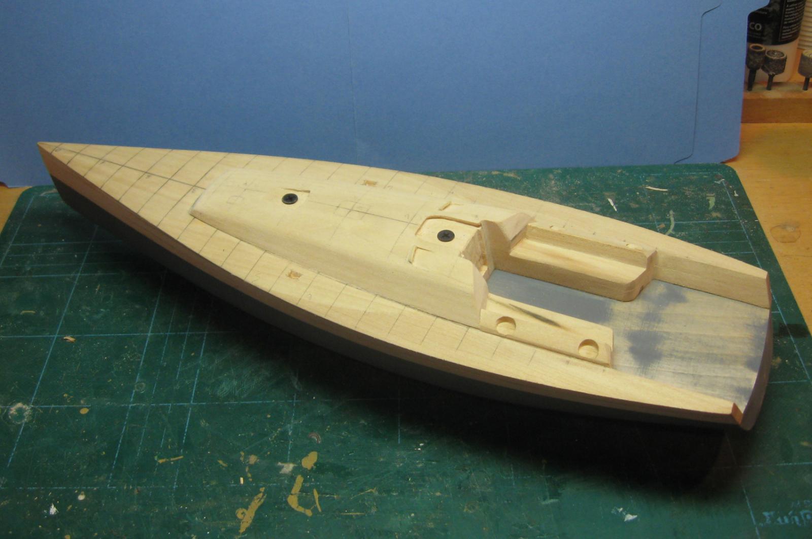
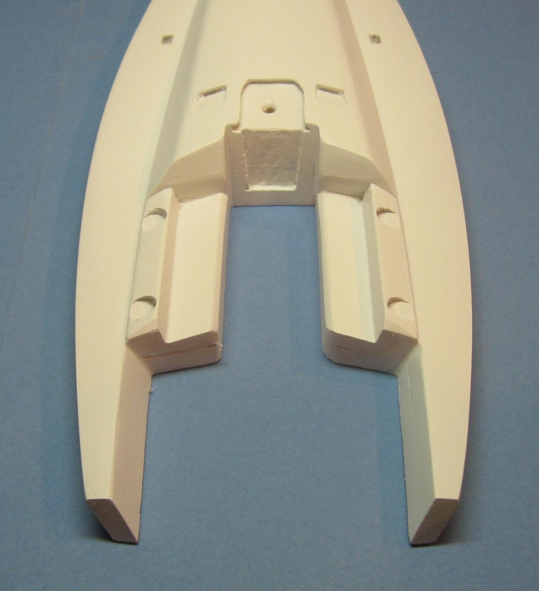
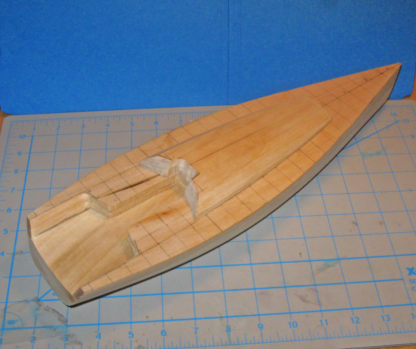
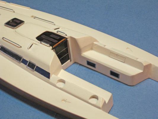
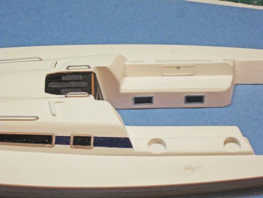
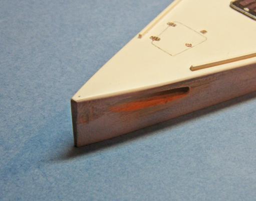
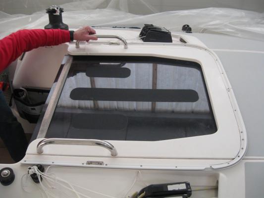
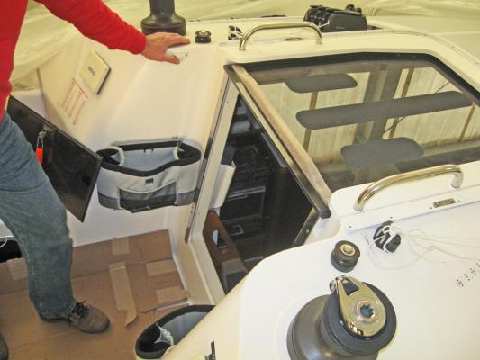
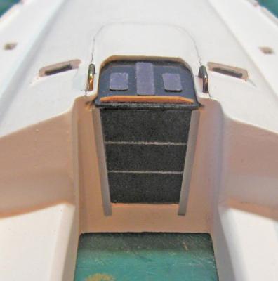
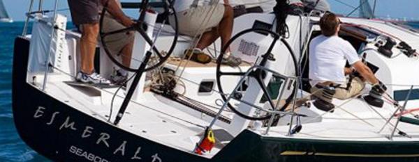
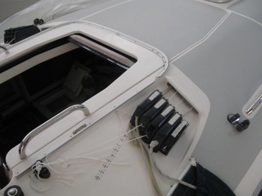
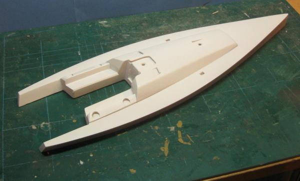
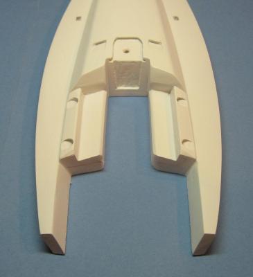
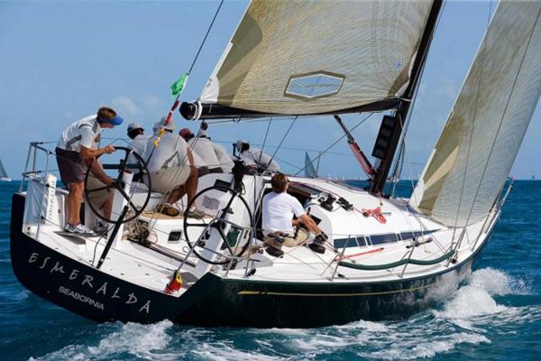
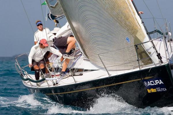
Hi all - The past week has been spent refining the cockpit area of the upper hull. The first photo is of an actual yacht focusing on the cockpit. You can see the compound planes and angles that form the integral bench, the seat back and the seatings for the two aft winches on each side. The two guys in khaki shorts are sitting on the tops of the seat backs with their feet on the benches. The aft cabin bulkhead is composed of several planes that meet at odd angles, with curves and fillets of assorted radius where they meet. You can see in the second photo how this has been carved into the wood. No secrets here, just files, sanding blocks with rounded corners, and a sharp #10 blade for the corners. Once the planes were defined, the companionway was attacked. You can see its size and shape in the third photo. It will be modeled closed. Alongside of the companionway roof are a pair of shallow angled ramps that lead down and forward. At the front end of each there is a small raised lip, and a flat tunnel which extends under the cabin roof to a similar carved depression at the base of the mast. On the ramp sit five line brakes for the various halyards and other rigging lines. You can see this in the fourth photo. In use the lines run down the mast, through blocks at the base, then into the tunnells leading aft, up and through the line brakes, then to the winches further aft. I saw the boat in drydock so the lines weren't there, which actually made getting a view of the details a little easier. I drew out the shape and location of the companionway on the wood, then started cutting down from the top about 1/8" to make the socket where a plate of smoked plastic will ultimately sit. It was roughly machined out using a milling bit in the miniature Dremel drill press (I'll get that Unimat one day). Smaller bits were used to progressively approach the pencil lines. Using a widely flared bitt I undercut the top, then used files to refine the undercut to match the look of the companionway roof. The vertical face of the companionway was cut down using side cutting bitts in a hand held Dremel. That's why it is rougher than the top face. The roughness will be hidden by the plastic door pieces and metal frames in the final model. The line brake seat on each side was carved out with sharp chisels, the raised lip was added and shaped, and the tunnel mouth was drilled out. After much work photo five is the final carved look of the companionway and line brake seats. The mast seating area was similarly carved out and the tunnel mouths there were drilled out. Finally, a pair of depressions were carved into the deck on either side of the cabin for small blocks that will be mounted later. Now the upper hull was temporarily mounted on the lower hull. Holes were drilled through the upper hull at the mast location and through the space where the companionway roof will be. The pieces were clamped together and screws were inserted and tightened, as you can see in photo six. With the two pieces locked together the sides of the upper hull were sanded to very close to their final shapes and matched to the lower hull. With all of the wood shaping being very close to final, the upper hull was given a coating of wood hardener. After drying, the whole hull was sanded smooth and then the upper hull was unscrewed from the lower. The last two photos are of the first coat of primer on the upper hull. I am using white here because the upper surfaces will be white in the final model. Much more priming, sanding, re-priming, etc. before the upper hull is ready for me to start on the hatches and other details. A biento, as the French say. Dan


-
Geez, guys - Nothing like putting some pressure on a fellow . . . This is a new direction for me too. I'll let you all know about the techniques that work, but I reserve the right to bury my mistakes quietly. Dan
-
Hi all - Here is another tip for tying ratlines - After you have clipped your lined off card behind the shrouds, put a dot of white paint on each of the outermost shrouds where they cross your lines. Now remove the card. This will give you your horizontal guideline while freeing up access to the back of the shrouds when you tie your knots. After all of the ratlines are done go back and paint over the white dots with black paint. Since the shrouds were tarred, if not the ratlines, this actually results in a more accurate look. I use clove hitches, myself, even down to 1:96 scale, although I have seen other methods that can be effective. I find them quick to tie and they slide easily up and down the shrouds to get the horizontal look right. At the outermost shrouds I use an overhand loop, which is small and neat, with the tail running down and behind the shroud. The tail pulls outward, so I can adjust the tension on the knots as I go, and helps in avoiding the hourglass problem. I find that using just this overlhand loop is the least obvious once the tail is cut off. I wrote an article on this method in the Nov/Dec 1989 issue of the old Ships in Scale magazine called "Get the 'Rats' out of your ratlines!" if you have the magazine or the CD. Dan
-
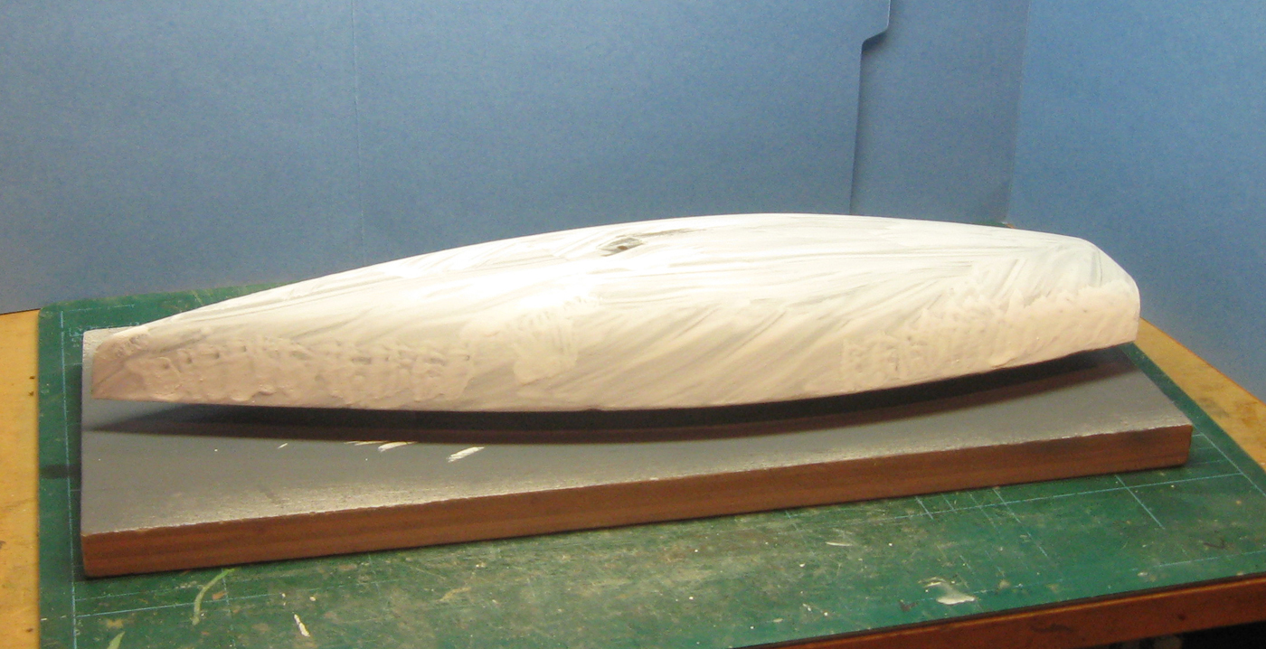
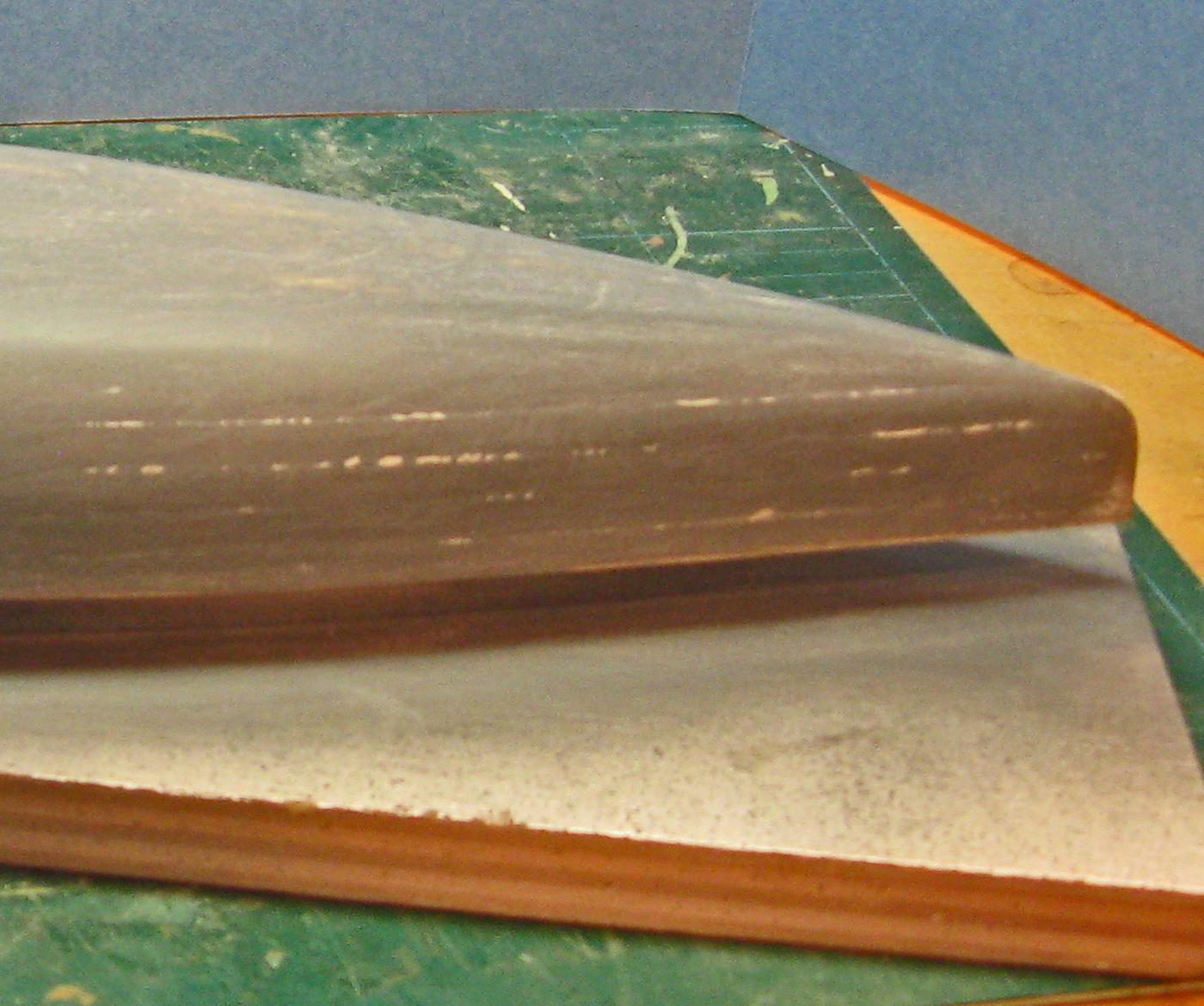
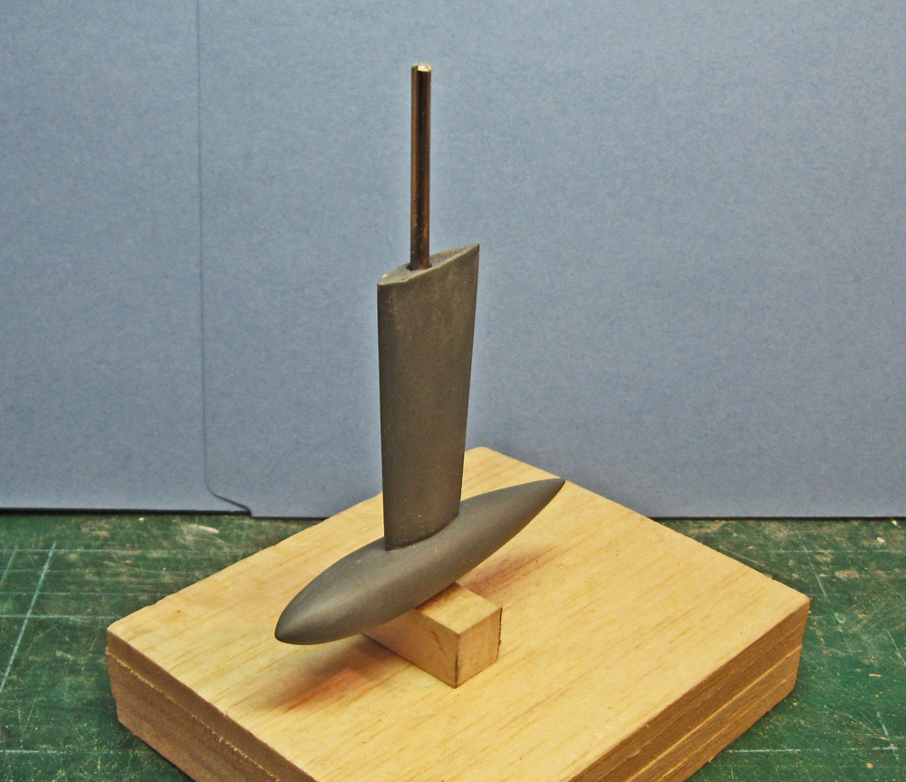
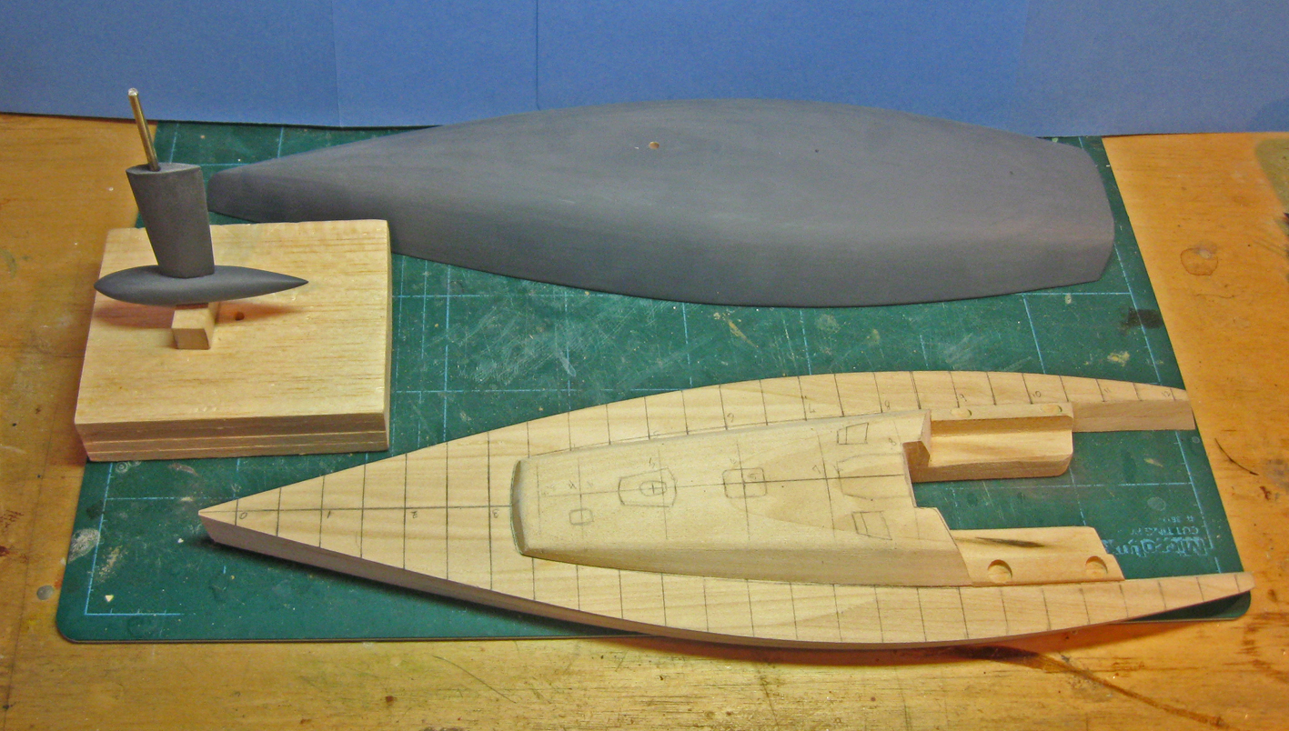
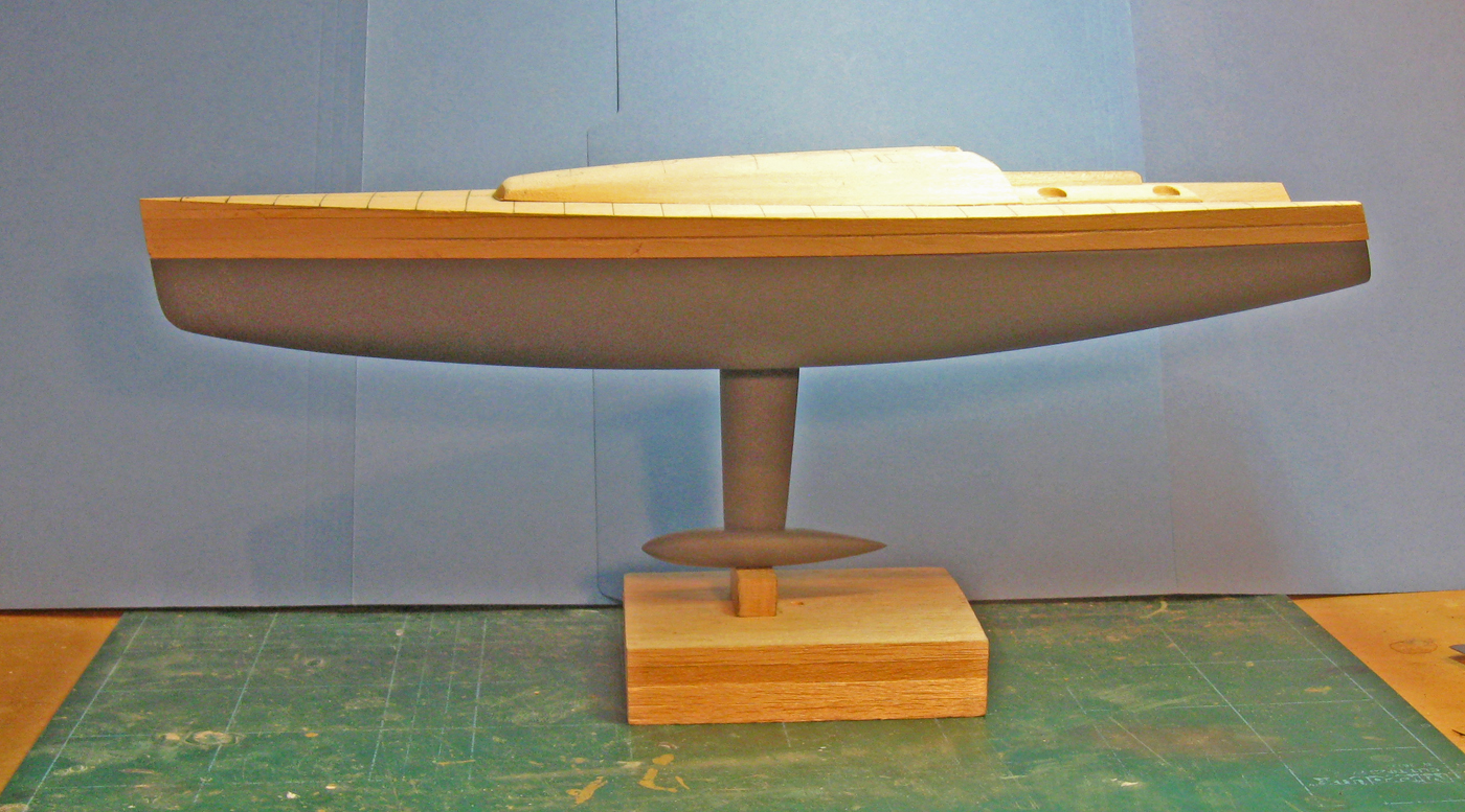
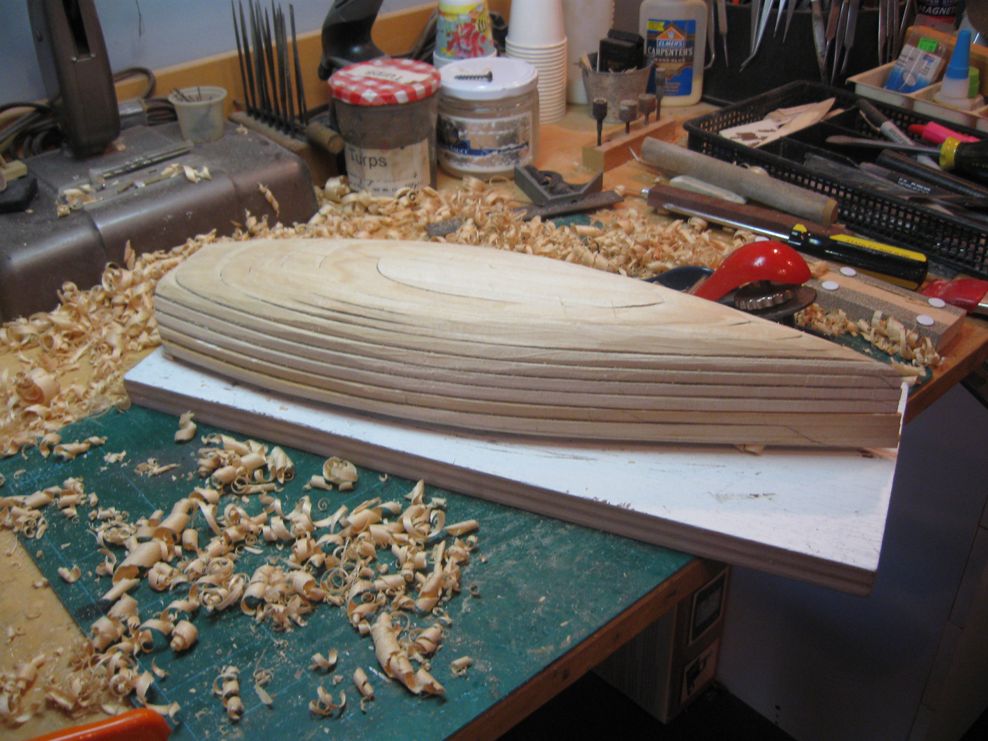
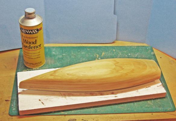
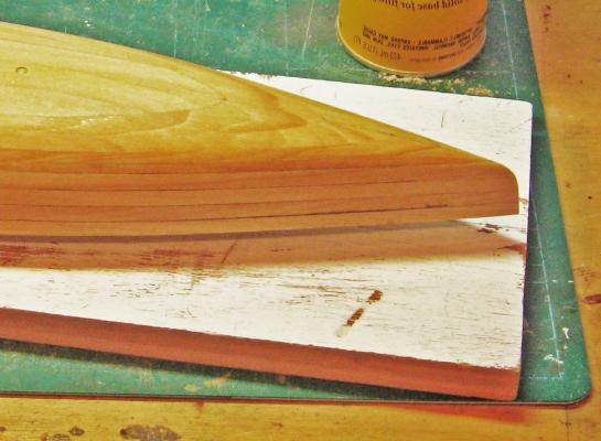
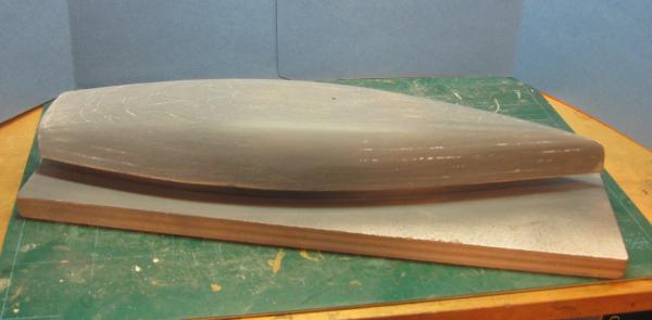
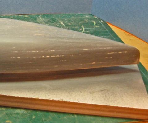
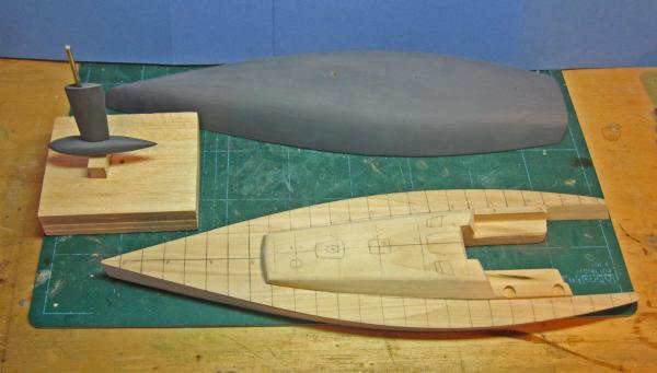
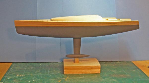
Now I turned back to the lower hull. It was refined with templates and progressively finer sanding blocks. After the 400 grit level I sealed it with Minwax Wood Hardener. This product is designed to strengthen rotted wood, but I have found it to be perfect for sealing wood where I want a truly smooth surface. The only drawback is that the wood becomes so hard that it is quite difficult to remove more than just a small amount - don't aske me how I know. I now hold off on using it until I am quite satisfied that I have the proper shape. After the hardener dried overnight it was sanded smooth to remove the raised grain, and the first coat of Krylon auto primer was sprayed on. This revealed that there were small imperfections where the various lifts had been joined to each other. These were filled by painting the entire lower hull with a thin solution of small-grained plaster. After sanding with a sanding block you can see where the plaster has filled the voids. The plaster was hardened and the next primer coat was applied, then sanded smooth. Ultimately, seven coats of primer were laid on and progressively sanded off with up to 1000 grit paper. The keel fin and bulb were similarly shaped, hardened, filled and sanded. Because the keel fin is so thin its connection points with the lower hull above and the keel bulb below would be incredibly fragile. I therefore planned for and fitted a steel pin that goes into the hull about 2 inches and down below the keel bulb about the same amount. I don't know how it will be displayed, but this should give them a great deal of flexibility in choosing the mounting for the model. So here is my progress to date. The three major components - upper hull, lower hull, and keel - can be stacked to see how they line up and to refine them as needed. More as the model develops. Be well Dan Pariser

-
Hi Tom - The model is not, directly, for the NYYC, although it may be donated by the owners' group to the Club. Despite my photo, I am not a sailor, so I have never been aboard a boat in the water. I had a chance to climb on deck of one in storage this winter to take lots of detail photos, and I will be getting aboard again once it is in the water this spring to photograph the mast, boom, and other running rigging details. The build continued with the upper hull cut out. The separation plane was chosen because it closely matches the floor of the cockpit, so the cockpit shape could be cut out of the upper lifts. These were roughly shaped to match the lower hull, with final finishing to await the time when the pieces would be joined. The sheer was created by laminating three more of the thin lifts of decreasing length to the top of the upper hull stack, then planed to the curve from the plans. The deckhouse/cabin was similarly cut and shaped, then refined with sanding blocks down to about 180 grit. Everything was left a little large to allow for final shaping. Once refined and matched to the sheer curve it was installed on the upper hull stack. At each step care was taken to draw centerlines and station lines. If they were removed by sanding and shaping, they were redrawn before the developing shapes were checked with templates from the plans. This was a process that was repeated at least 30 times during the shaping process.

-
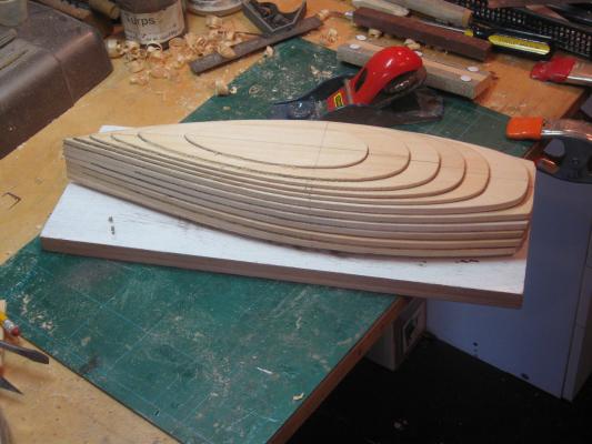
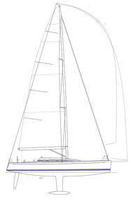
Hi Bob - Thanks. I'll try to keep up the level of my work. Here is the second installment: The model was specified to be in 1:32 (3/8"=1') scale, so I first sized up the plans provided to the exact size of the model, just under 16 inches LOA. Looking at the plans I determined that the best way to shape the hull was by a series of horizontal lifts. I took the waterline lift half-plan, mirrored it in Photoshop and combined them to make a full plan that could be cut out to the exact shape of the lifts. This was printed out and mounted on a stiff file folder. The profile view provided the thickness of the lifts. Below the waterline they are almost exactly 1/8", while above it they are double that thickness. As with most of my model hulls, I like to find a convenient horizontal level to use as a reference plane. The hull below the line and above the line are shaped and treated as separate components until quite late in the build. This allows me to lay each piece flat on a work board for ease in shaping it, or on the platen of a drill press to make precise holes or to do any milling that can be done. The stiffened plan was cut out in sequentially larger lifts. Each was transferred to basswood of the appropriate thickness, and a centerline drawn on. A perpendicular was drawn at station number 6 so each lift could be registered against its neighbors in both dimensions. These were glued, one at a time, to make a stack up from the bottom of the hull to the separation plane, and down from the deck. When everything was secure the shaping began with a small block plane.

-
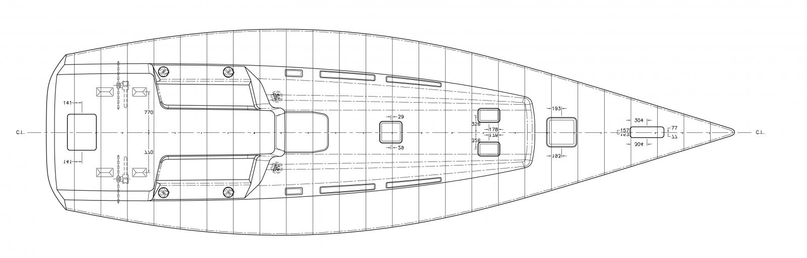
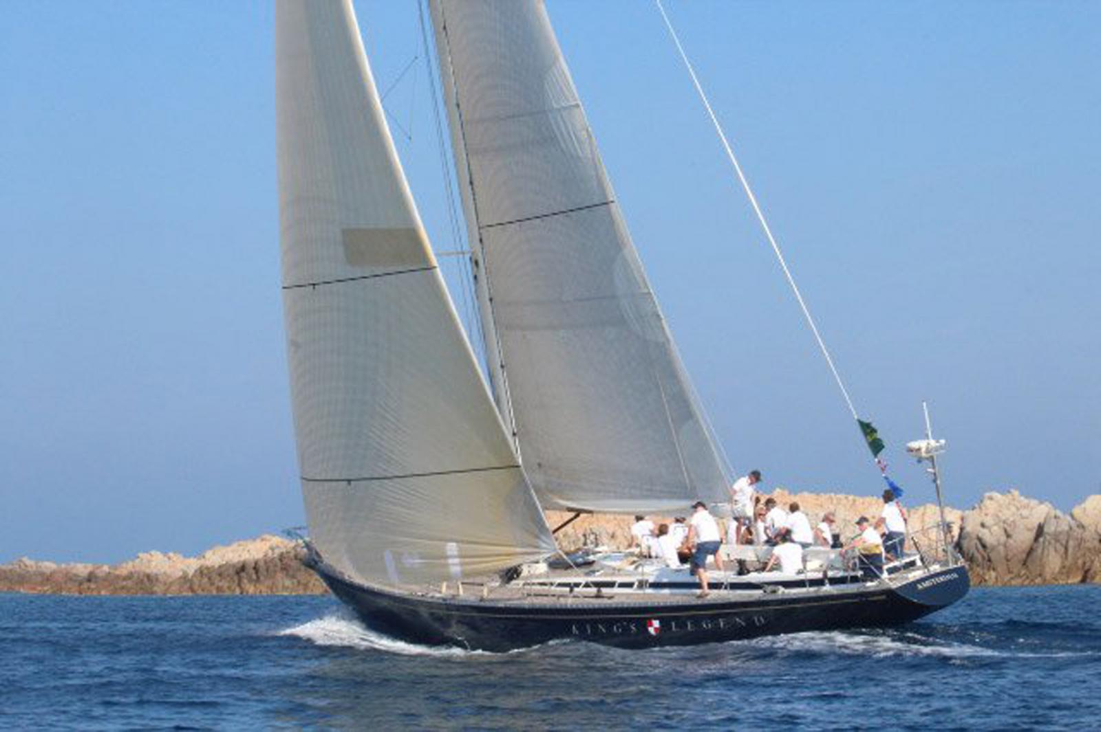
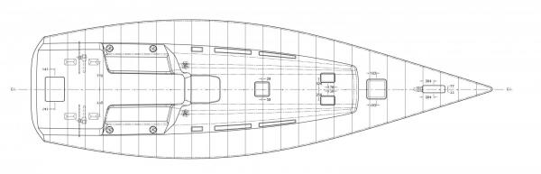
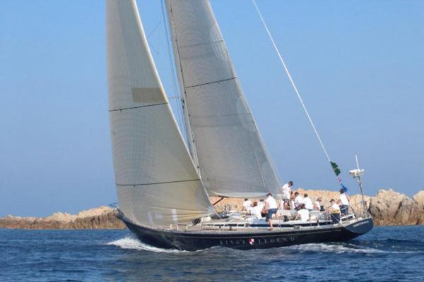
Hi all - Here is my first build log. I'll try to make it complete and comprehensive, but please let me know if I don't explain things too well. This is a commission from a group of owners and racers of this cutting edge design. A one-design yacht is where an agreed upon design is built by all of the boat owners and then raced against each other. This reduces the effect of technology and puts a premium on sailing tactics and boat handling. The latest design that was chosen was a 42 foot version of the Swan line of boats built by Nautor of Finland and designed by Frers Design Office. The first hull came off the ways in 2005, with about 45 more in the water today. I was provided with some proprietary plans and drawings which are accurate down to the millimeter. I cannot reproduce them, but here are some drawings that are available on the internet, and some photos of boats on the water.
-
ROYAL CAROLINE 1749 by Doris - 1:40 - CARD
shipmodel replied to DORIS's topic in - Build logs for subjects built 1501 - 1750
Doris - I am somewhat new to the MSW site and still working my way through all of the wonderful build logs. Yours is one of the best. Thank you for sharing your progress. I will follow it with interest. Be well Dan Pariser- 883 replies
-
- 1
-
-
- royal caroline
- ship of the line
- (and 1 more)