shipmodel
-
Posts
941 -
Joined
-
Last visited
Content Type
Profiles
Forums
Gallery
Events
Everything posted by shipmodel
-
 I expect that I will never build a miniature engine, much less a working one, in my modeling lifetime, but I am immensely enjoying following your work. That was a truly elegant and practical solution to your slip. Dan
 -
Hi Mark - Just catching up with your build. Looking mighty nice. Let me add my compliments to all the others. V2 is coming along beautifully. I took your last photo, enlarged it and flipped it over to really appreciate it. The Hahn method may build the hull upside down, but I can see it better right side up. Top quality work, my friend. Will you be carving the details with your light saber? Dan
-
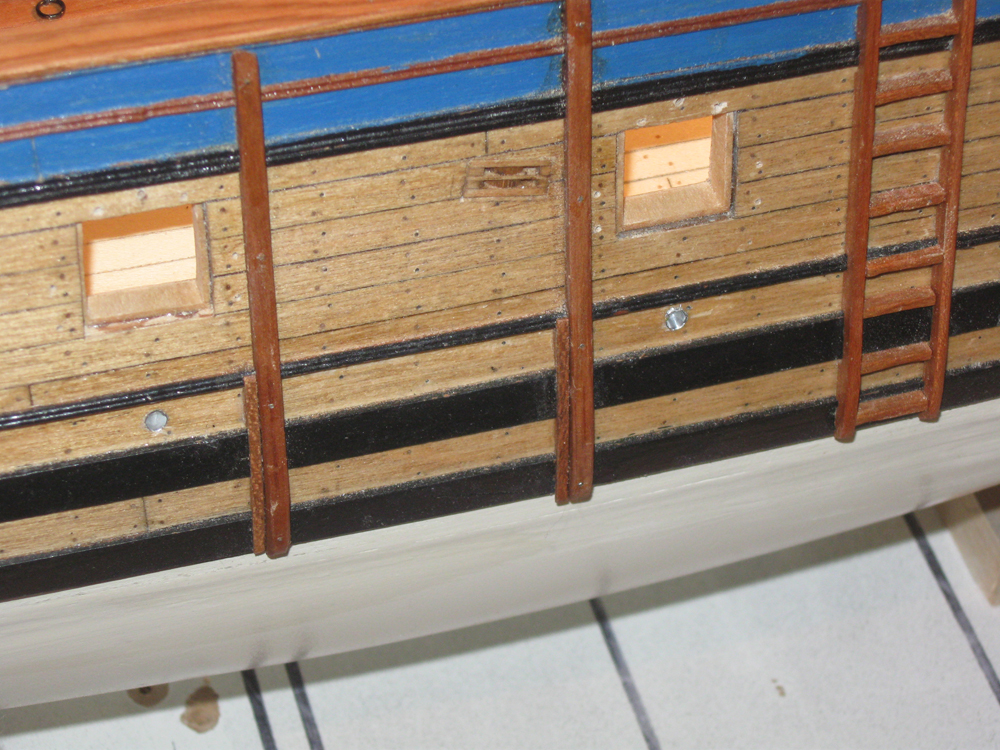
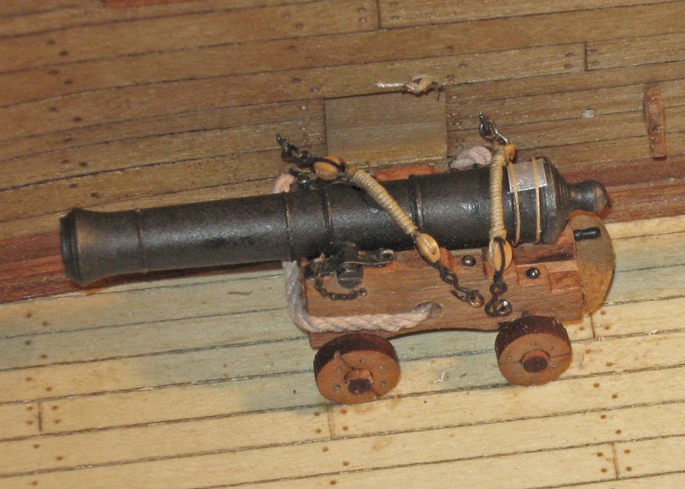
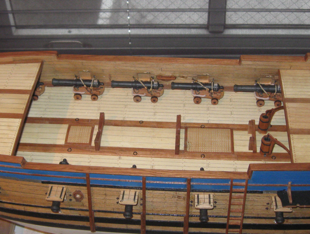
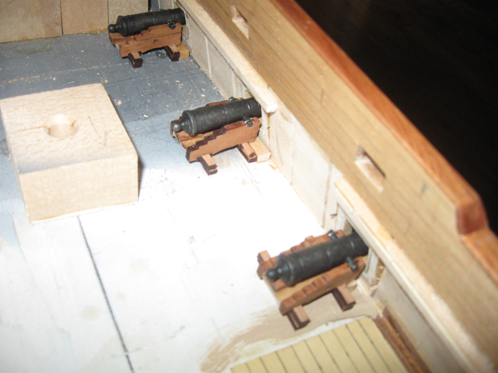
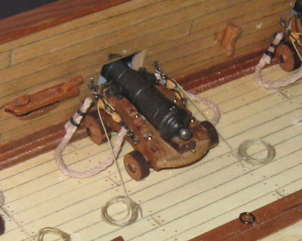
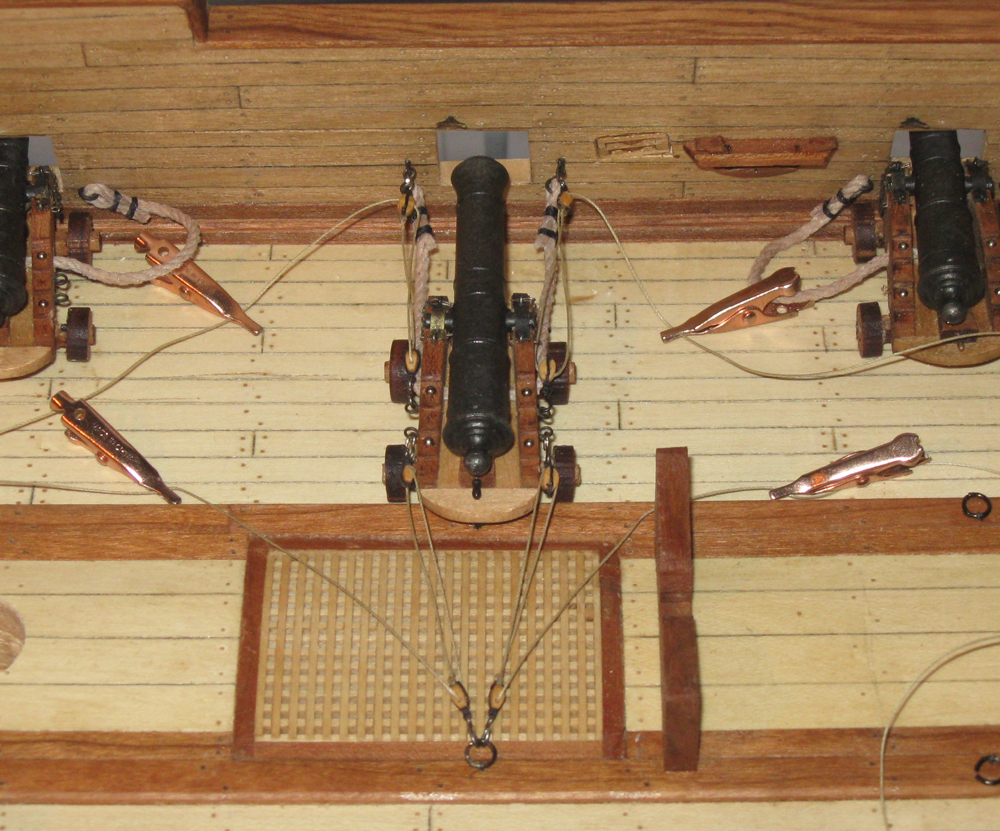
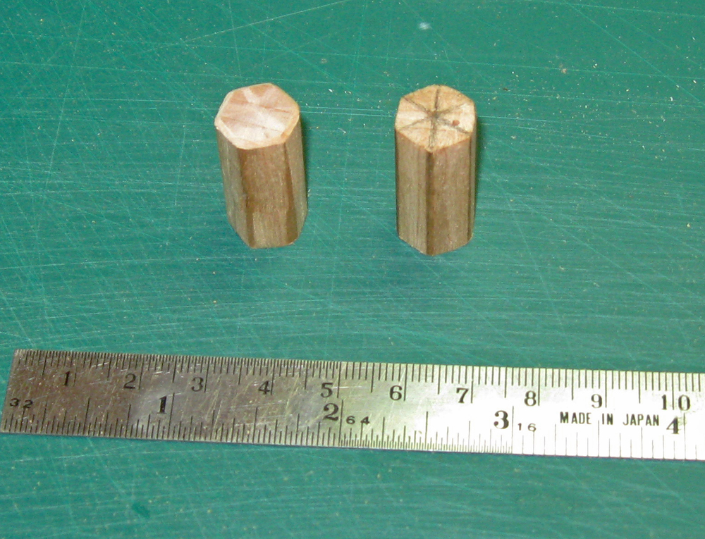
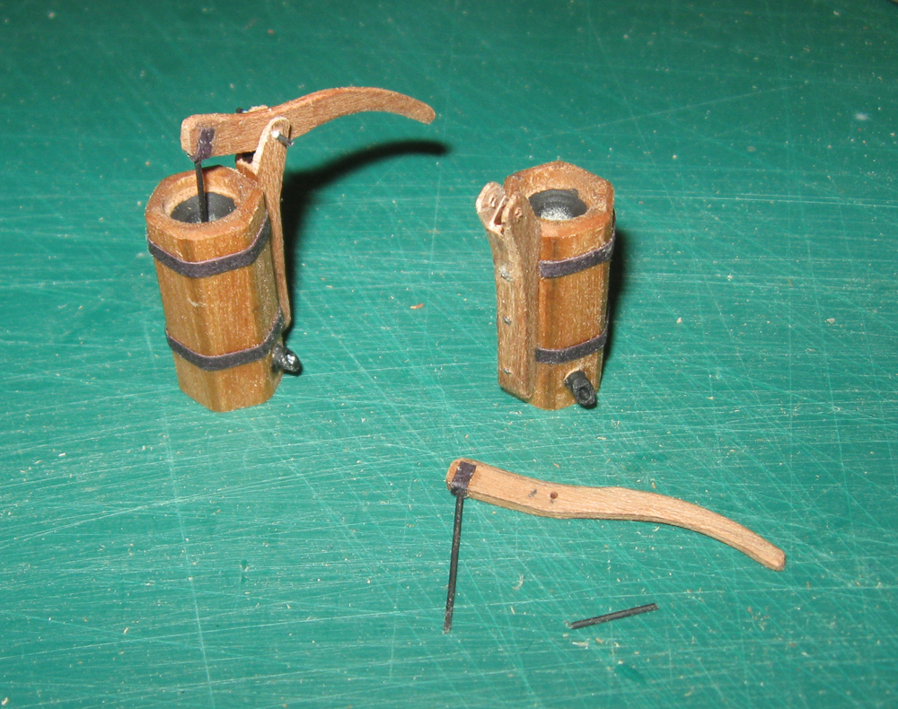
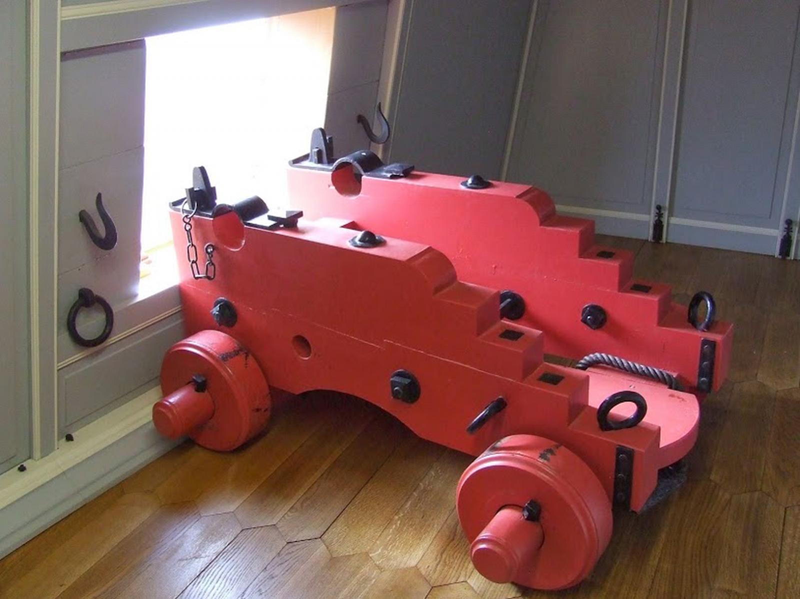
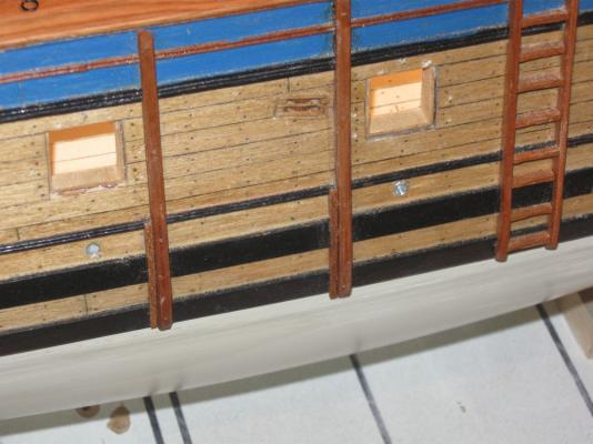
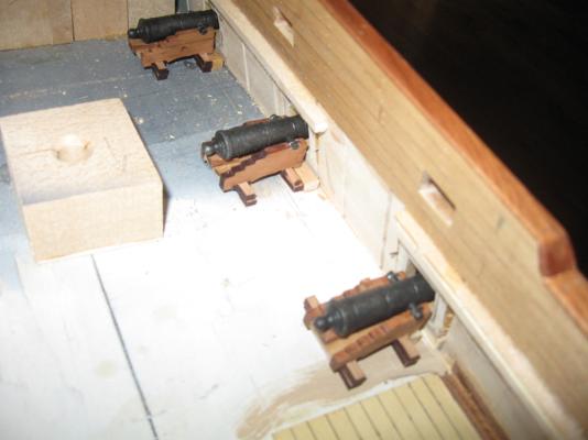
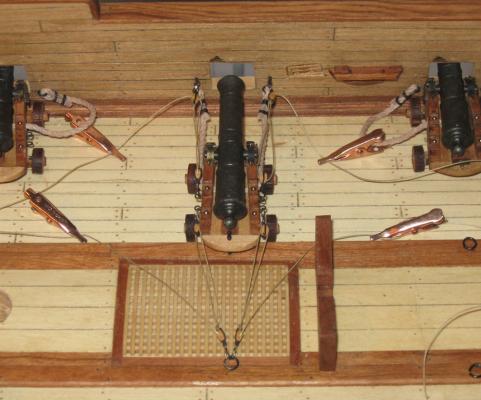
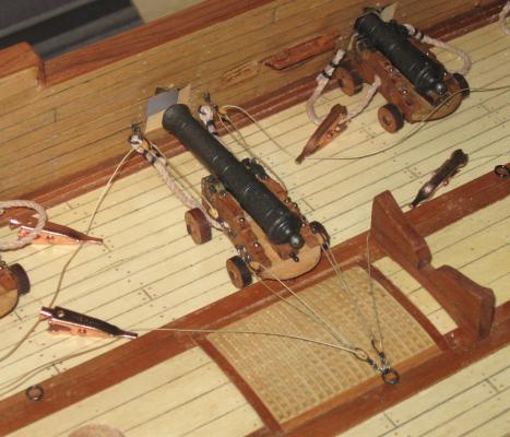
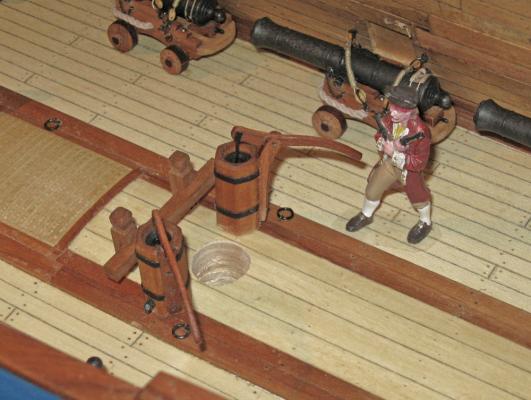
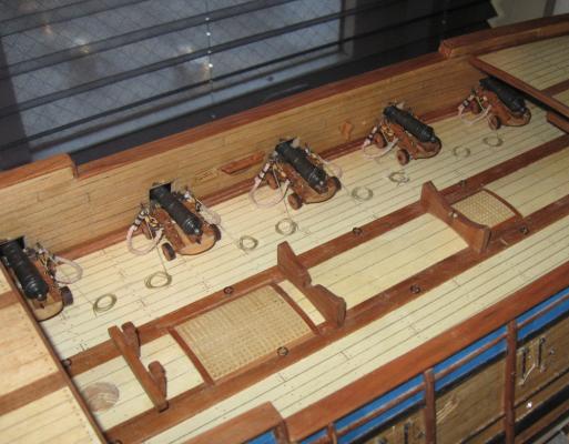
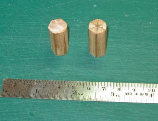
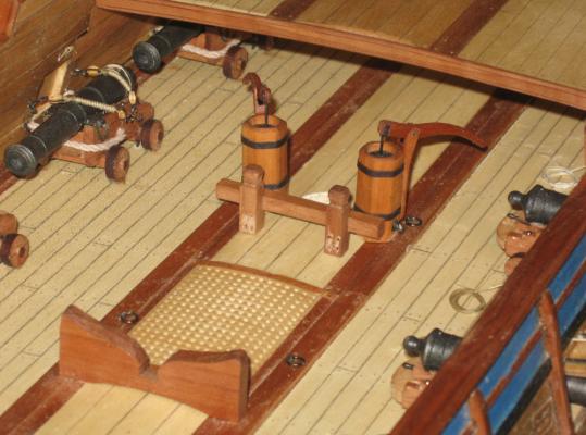
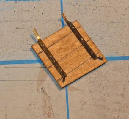
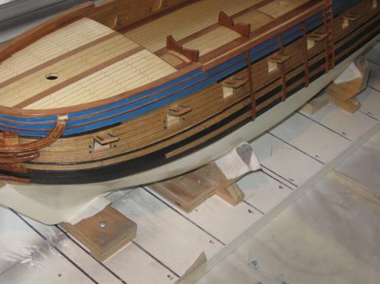
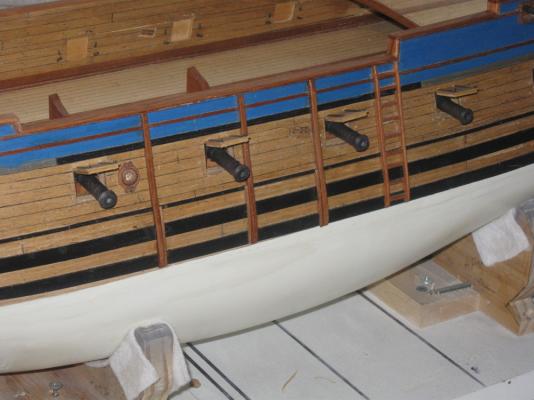
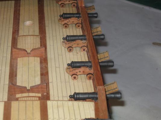
HI all - After finishing up some other projects and some chores on the "honey-do" list, I am back building the QAR. Here is my progress. I realized that I had not planned or installed any scuppers from the gun deck to the outside of the hull. Using a set of outside calipers I located and drilled five on each side of the hull. I lined them with lead from a wine bottle wrapped around a toothpick, glued, and slid into place. Once the glue was dry the excess was trimmed with a sharp blade. They fit well when they were located under the gunports, though this meant that the upper ends in the waterways at the edges of the deck were all hidden by the guns. Here are two on the port side of the hull. 1 Next I turned to the guns. First were the stowed guns on the starboard side. I played around with the test gun station that I made up a while ago to see how it might have been done. I figured that the crew would have used the breaching rope and the train tackles which were already available. I found that the breaching rope could be tightened up through the rings in the bulwark, which would have secured the gun pretty well. Then the train tackles could run from the eyebolts on the carriage to the hooks in the bulwark. Once they were tightened the remaining length of running line could be frapped (overwrapped) between the blocks. I found that two layers perfectly used up the free line. This seems a workable solution, but there certainly can be others. Note that I have installed a lead vent cover secured with light line, which would have been used to keep water from entering and rusting the vent hole. 2 Here is the line of four stowed guns in the waist. The guns are secured with a metal pin through the rear axle and into the deck, which is hidden between the truck and the carriage. There are two others, one forward under the foredeck and one aft under the quarterdeck, which can only be seen at a low angle. Those that cannot be seen were not installed. 3 On the port side the guns are run out, so all of them can be seen to some extent. The three aftmost and the one in the bow were simplified. The trucks were replaced with cleats for added glue surface and security, while the capsquares and rigging were not installed. These were pinned in place as well. 4 The visible guns were glued to the deck and a metal pin was drilled at an angle through the rear axle and into the deck. The breaching rope was rigged through the rings in the bulwark and secured to itself with two round seizings. The rope was softened with water and shaped to 'droop' onto the deck. Once it was approximately positioned it was painted with dilute pH neutral white glue and teased into final position as the glue dried. This also secured it to the deck. The train tackle was rigged from the carriage eyebolts to the bulwark hooks with the running line coiled on deck. I did not flemish the coil since I do not think that a pirate ship would be that 'shipshape' or fastidious. 5 As long as I was rigging the guns, I experimented with loading procedures. I was surprised to see that when the gun was fully run in for loading the back of the carriage covered up the deck ring behind it. I double checked the length of French six-pounder cannon and the breadth of the deck and they were correct, so it is likely that this was what happened. The only way I could make the system work was to hook the run-in tackle to the ring on the opposite side of the deck. 6 With the copper clips standing in for the gun crew this seems to be a workable solution. But again, this is speculation and may not be correct. 7 The rest of the port broadside was installed and rigged. 8 There are no pumps in Budriot's plans, but they do appear in a photograph of Berti's model of Le Mercure. His are round, which I did not like, so I made mine hexagonal. This was done in a straightforward way. A length of half inch maple dowel was cut and the end marked with a six pointed star. The lines were extended down the dowel then the wood was carved away between the lines. The pump bodies were cut to length and the sides adjusted by hand sanding. 9 The well at the top was drilled, milled and darkened. Blackened brass reinforcing rings were installed, as was a blackened brass outlet near the base of the pump. The yoke for the handle was fashioned, installed and secured with three metal pins. The handle was shaped and given a pivoting lifting bar at the business end that dropped into the well. The handle was mounted on a metal axle pin through the yoke and the finished pump was given a coat of clear finish. 10 The completed pumps were installed adjacent to the main mast location. Their bases had to be angled slightly to match the round-up of the deck, then secured with metal pins into the deck. The handles are angled outward where they can be accessed easily by the crew without getting in the way of the rigging to come (at least I hope that there will be no problems). 11 Using Pirate Pete for comparison, I am happy with the size, scale and look of the pumps. 12 More soon. Be well. Dan


- 241 replies
-
- 15
-

-
- queen annes revenge
- pirate
- (and 2 more)
-
David - All my best wishes for continued and complete recovery. What a scary time that must have been! So glad that you came through it and can see the light at the end of the tunnel. The Maine had her own troubles too. Glad she came through OK as well. Maybe if you write to the manufacturer or retailer and explain your problem they will provide replacements for the missing sheets. I know that if it were Bluejacket or Expo they would do it without a second's hesitation. Be well Dan
-
Michael - Just catching up on my reading after the NRG conference. Nice progress while I was away and very nice work. The transition from the inside rabbet of the stern to the outside rabbet of the keel is not child's play by any measure, and you are making it look easy. Looking forward to seeing the engine come together. Dan
-
David - I have lots of photos if they would help. Feel free to ask and I can get them to you. It may be easier to run off a disk and mail it to you than to try to email them. Just send me your address. Dan
-
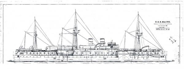
Hi David - Coming along quite nicely, given the limitations of the materials. It is really taking shape. Don't worry about comparing it to my model or anyone else's. I know that there are a whole pack of mistakes in my model that, hopefully, I have corrected or covered up. BTW - the 'v' shaped fittings to either side of the gangway between the center and aft deck houses were supports for a pair of large motorized cutters that were never fitted on the ship. They did find a use for the scaffolding, which was to stow extra spars and even the rolled up set of sails that were originally designed for the ship, in case it ran out of coal in mid-ocean. Here is one of the earliest plans for the ship, with three masts and raked smokestacks. Keep up the good work. I will be eagerly watching for future installments. Dan
-
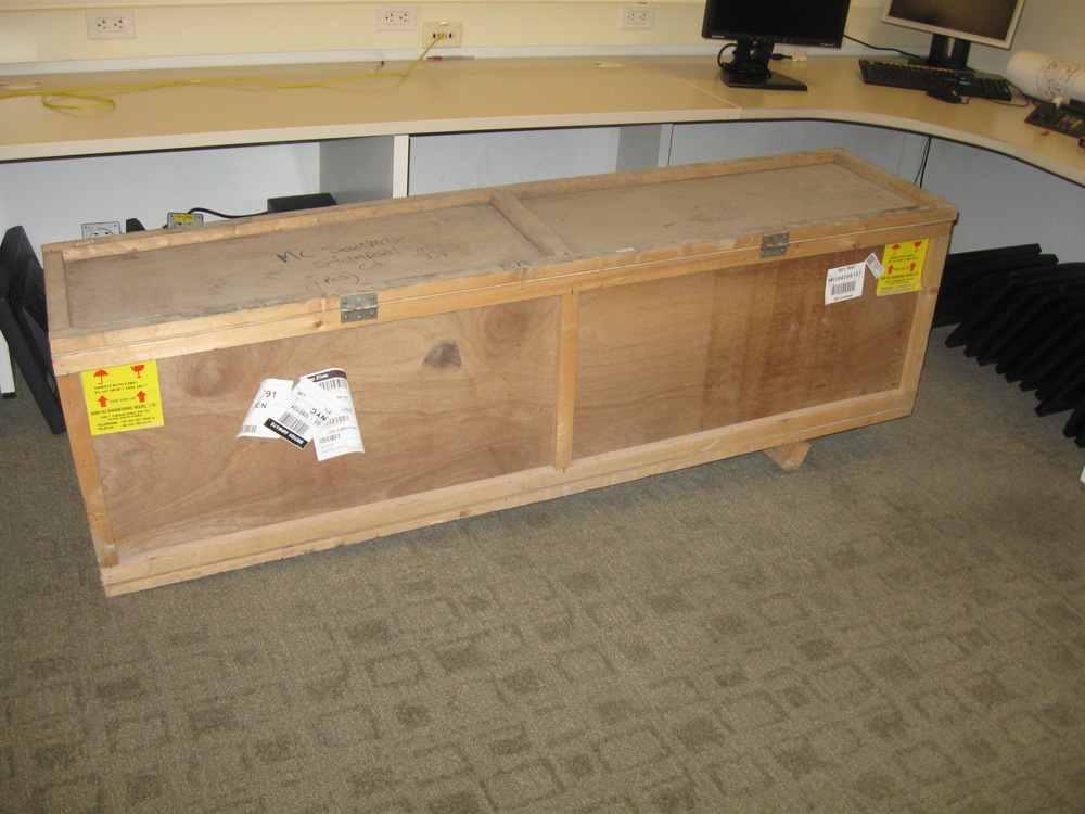
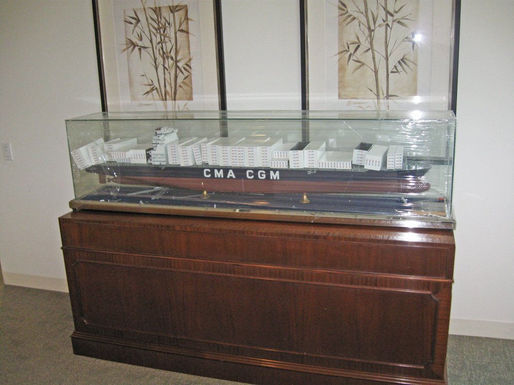
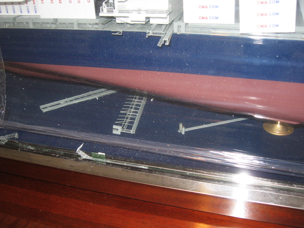
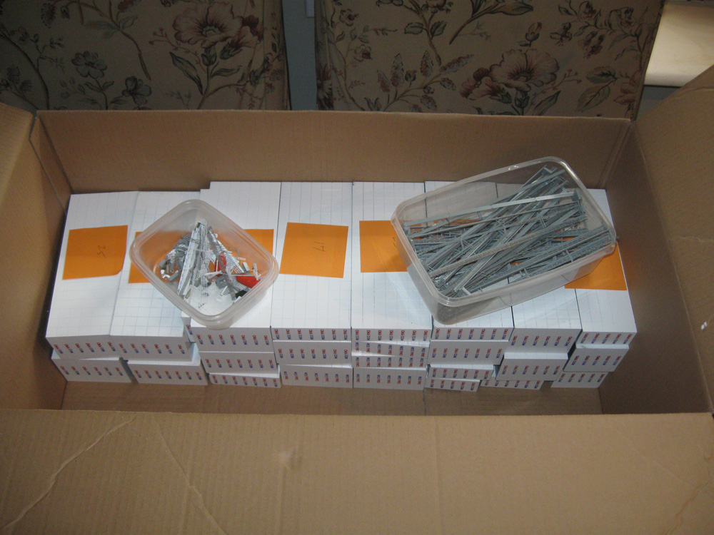
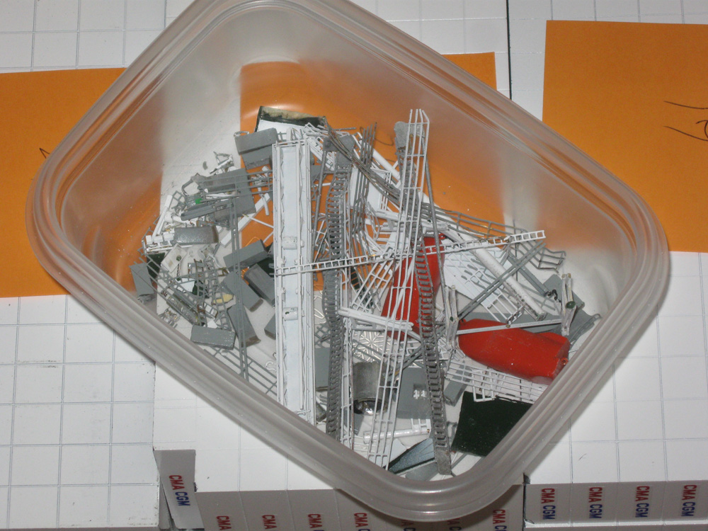
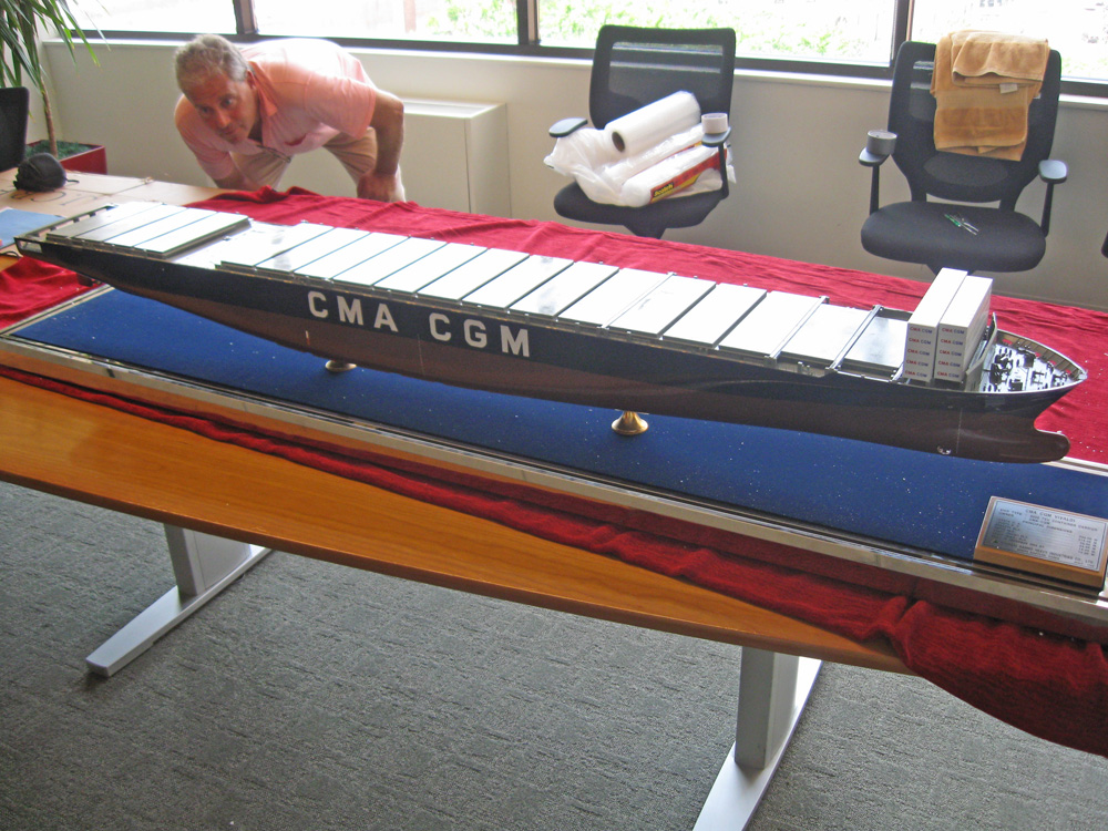
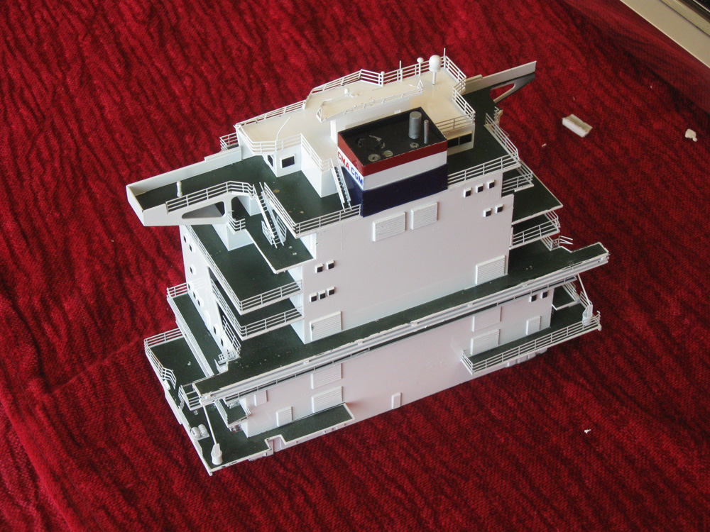
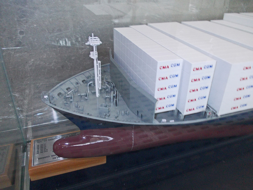
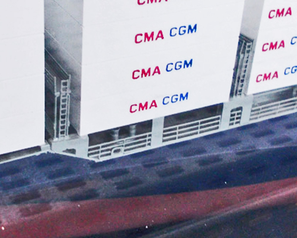
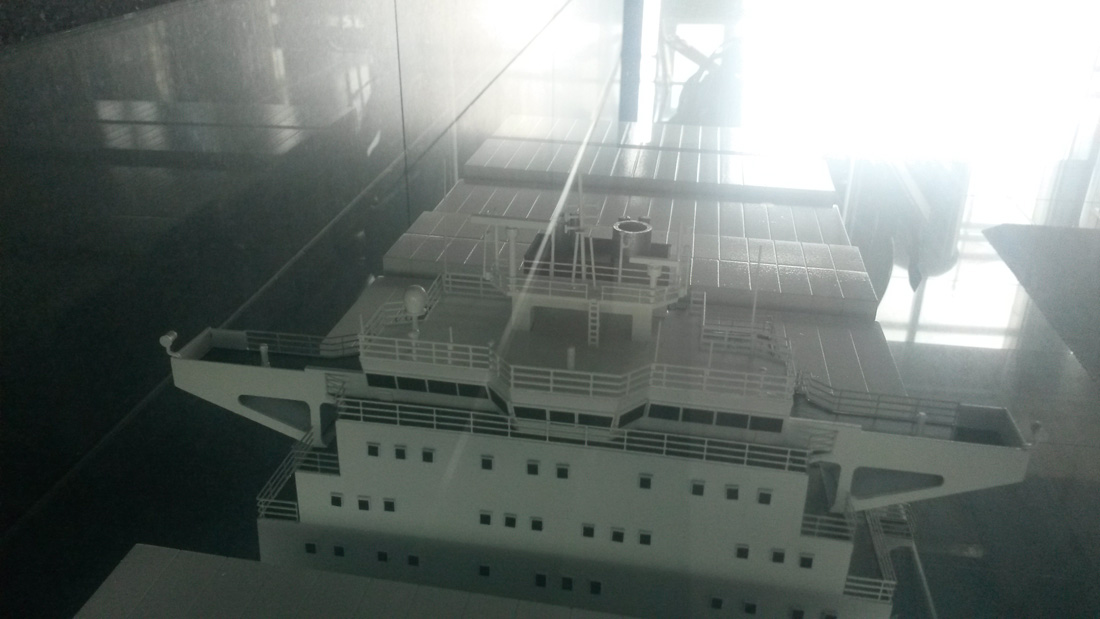
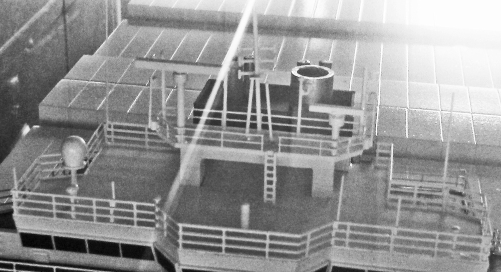
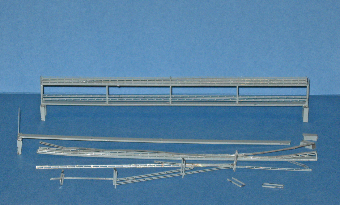
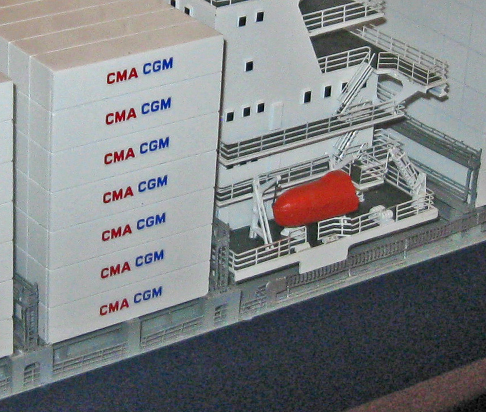
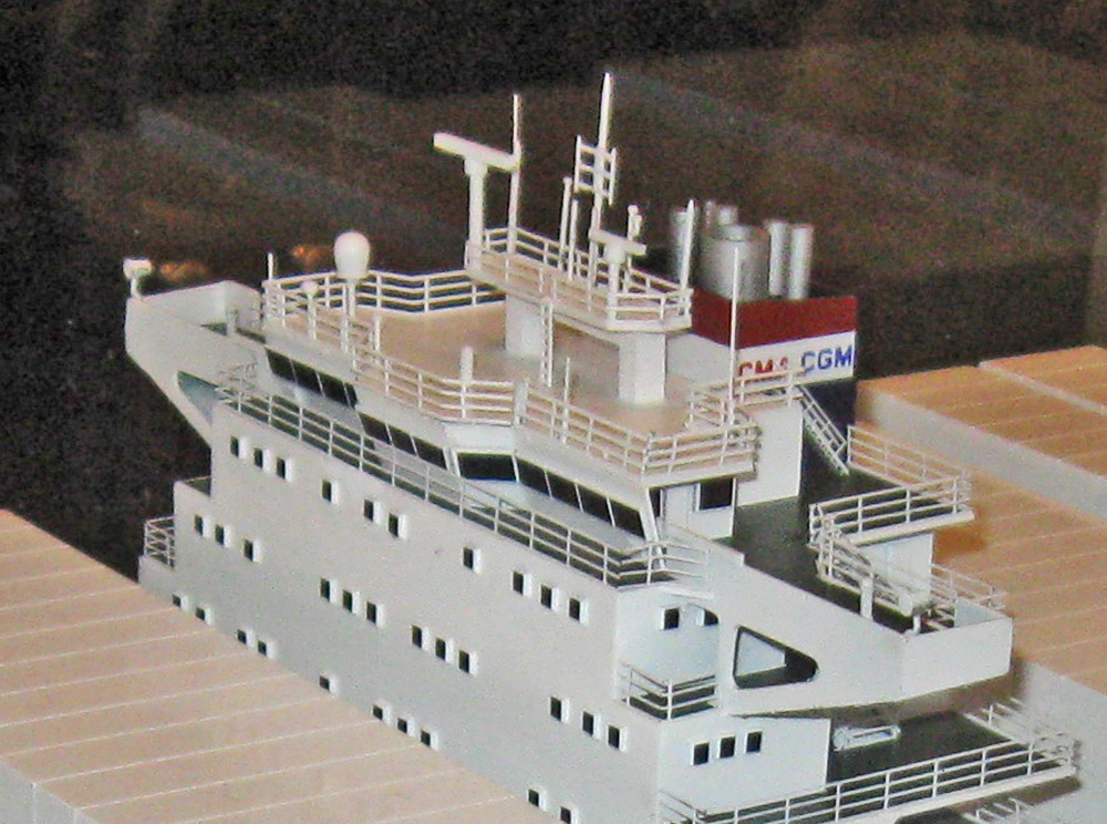
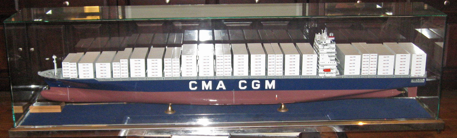
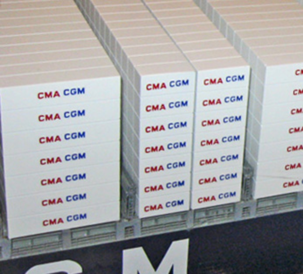
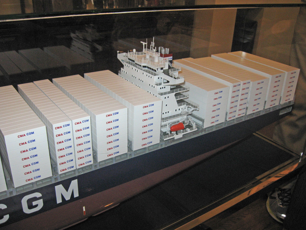
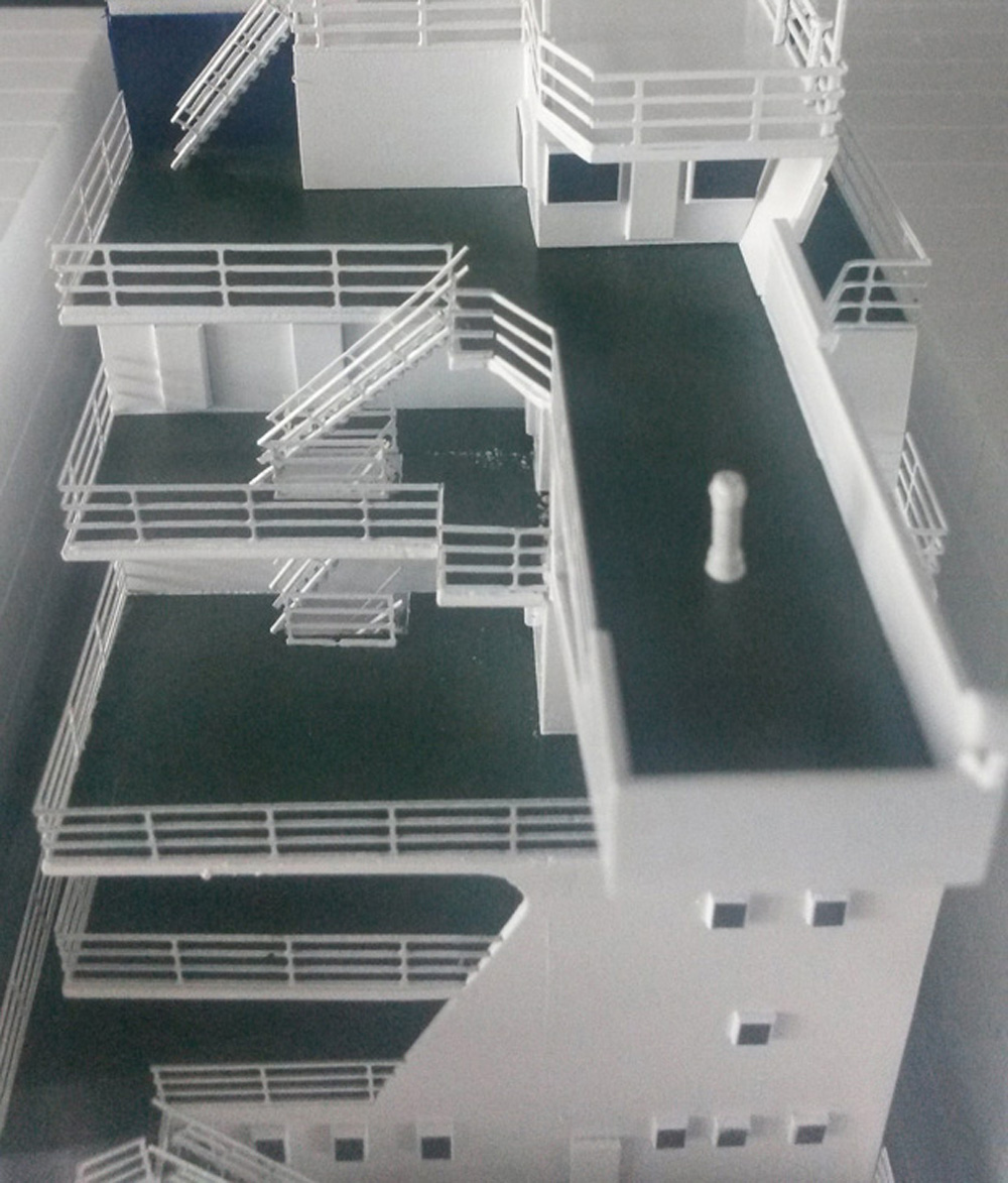
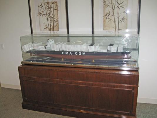
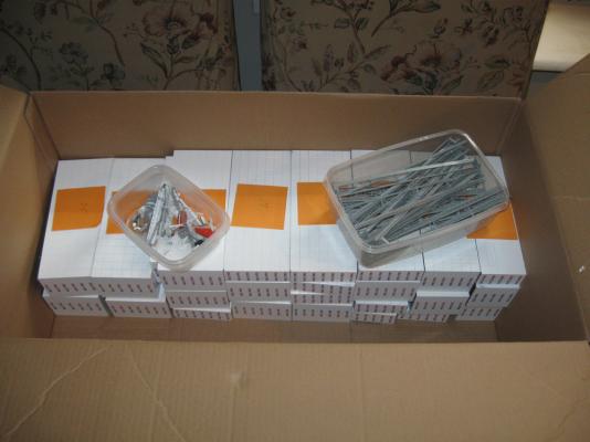
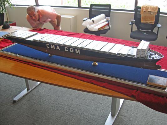
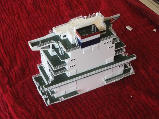
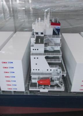
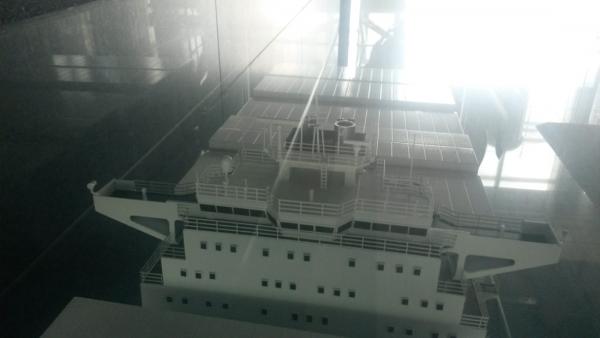
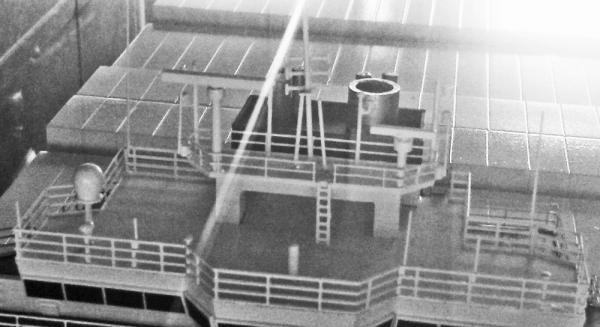
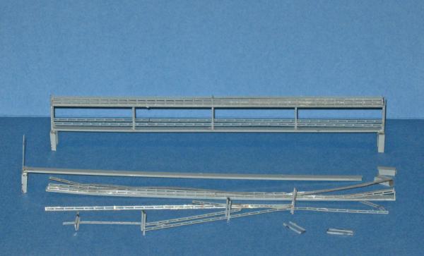
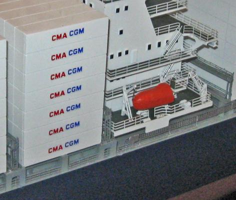
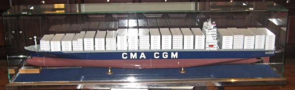
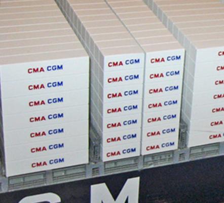
Hello to all who are following this build - It has been a while since my last posting. Summertime had a lot to do with it, but I also took some time away to work on a short-term and time critical project. So here is a little diversion from this build. It may merit a separate file, but as you will see later on, it is incomplete. I was asked to restore a presentation model of a modern container ship. The CMA-CGM Vivaldi was built by Hyundai Samho Heavy Industries Co., Ltd. in their Makpo Shipyard in South Korea. Launched in December, 2004 she was 334 meters LOA with a breadth of 42.3 m (just under 1100 ft LOA, 140 ft breadth). Its carrying capacity was not listed on the dimensions plaque on the model, but it is huge. Here she is in a photo from the company website of CMA-CMG Shipping, which owns and operates her as part of one of the world’s largest fleets of container ships. 1 The model was likely built in the same shipyard as a gift to thank CMA-CGM for the contract and was presented at the time of launch. It is built to the small scale of 1:200, but the model is still 5 ½ feet long. Given that the price for the ship was in the millions of dollars, it is not surprising that a good deal of care went into the construction of this presentation model. It was probably kept in one of their offices, perhaps in their headquarters in Marseille, for the last decade but then was presented in turn to a financing company in Stamford, Connecticut. It was during the delivery of the model that things went bad. Here is the crate that it came in. You can see that although there is no obvious damage to the box itself, one of the bottom cleats is missing. 2 I was called in when the box was opened and it was found that one of the glass panels of the case was cracked and there was some damage to the model. My first overall impression was that this was not going to be a hard job. Some of the containers had been detached from their mountings and were tipped over, but they were still on deck and in a line. The superstructure was in place and there was no evident damage to the hull. 3 Closer examination revealed that the devil had been playing in the details. A large number of small pieces were lying on the blue felt base and some had even become trapped in the channel that the glass case sat in. Fortunately many of them, including some quite complex assemblies, appeared undamaged like the one in the center of the photo. 4 A repair proposal was discussed, a fee agreed to, and work began with the recovery and conservation of any detached parts. Once the wrapping of clear plastic was removed the impact point could be seen. It was clear that there had been one sharp blow which had chipped and cracked the glass panel, but without separating it from the rest of the case. Unfortunately, this is exactly the kind of impact that cyano glue does not like. With the help of JerseyCityFrankie the glass cover was removed and all of the loose parts were carefully collected. The detached container units were numbered from the bow to the stern on sticky notes and set aside. The grey railing units could not be immediately identified, but they were put into one container for later study. All of the smaller parts such as the lifeboats, ladders, white railings, and various unknown pieces were put in another. 8 9 Now the full extent of the damage could be seen and assessed. Along the edges of the hull most of the railings and stanchions were broken off, leaving unpainted spots showing where they had been attached. At the stern there was additional damage where the railings and ladders had been crushed and even some pieces of the rigid styrene components had been broken. When everything that was loose had been removed the deck was almost nude other than two container units at the bow that had somehow managed to remain in place. This was packed up in bubble wrap and taken back to the studio in Brooklyn, NY. 12 The superstructure which had initially appeared to be generally sound was found to have suffered the most damage. In additional to losing both lifeboats, most of the railing on the aft face was gone, as were numerous small parts for the lifeboat cranes. All of the various radars and antennas on the topmost level were missing. Most significantly, the starboard bridge wing was broken off almost completely. 13 Although the proper locations of many of the pieces could be deduced from what they were, there were a great deal more that could have gone anywhere. Fortunately the company had a second presentation model of the same ship, the Vivaldi. A series of photographs were taken of the other model to guide the restoration. Here is the bow, showing the white lookout mast which had been detached on the damaged model. The ladder and safety cage had been separated and crushed, but now I could see how they had to be repaired. 14 Those gray railing units turned out to be catwalks that fit between the container units. They sat on top of U-shaped pieces that supported the containers. Photoetched ladders gave access to upper catwalks which were bordered by photoetched brass railings. 3-bar railings edged the deck all along the sides of the ship. 15a The superstructure had 8 deck levels with a full array of electronic equipment on top. 16 This area was going to be the most challenging, with radars and antenna that were all made up of very small parts that were quite similar to each other. The photographs that I was sent were not completely helpful in specifying what went where. Fortunately, using my Photoshop program I could take the image provided and enlarge it, remove the color, and play with the brightness and contrast until I could see almost all of the details. 17 18 Now that I had the undamaged model as a guide I could start the actual repairs. The first thing was to reassemble all of the catwalks. Some were in pretty good shape, but others had been mauled, with most of the parts separated, some of the plastic parts broken off, and the photoetched brass rails badly bent. Here is one of the catwalks with all its pieces and a second one after restoration. There were 21 of these in all, which took up about half of the total restoration time. 19 Now for the incomplete part - The next several weeks were spent doing the restoration. I took construction photos as I went, as usual, but had not gotten around to downloading them. [i know you can see the problem coming . . . ] Soon after I took the last photograph, my daughter and her two boys came over. One is the newborn, the other 2 years old. While I was doting on the young one, the other found the camera. He likes to push buttons. Enough said. Let me describe what I did, and I hope you can follow along using photos of the completed repair. All of the least damaged catwalks were put back together. Since there were small variations in how the bases had broken off of the hull I could locate about two thirds in their original positions, fitting them together like a jigsaw puzzle. They were numbered and set aside. One by one the rest were repaired until there were only two left, which were severely bent, with missing parts. Some replacement parts were fabricated from bent wire, and others from brass shim. Missing ladders were replaced with similar ones from the spares box. 21 Starting at the bow and working aft the containers and catwalks were glued to the cleaned up hull. The containers sit on the corners of the catwalk bases and on a square stanchion between the forward and aft bases located on both edges of the deck. This gives six attachment points for the double wide containers and four each for the single wide ones. These also broke off irregularly. Although each container unit was numbered when it was removed, several ones were out of order, and I had not recorded the orientation of the unit. Each one was test fit to the proposed location and the irregularities let me confirm the original locations. 21a The superstructure was the biggest challenge. I first relocated the lifeboats and repaired their cranes. Railings which were bent were carefully bent back and glued. Some that had been detached were too badly bent to repair. I had 3-bar railing of the right size in my spares box, but the rails were a bit thinner than those on the model. I used them to replace the railings that would not be seen easily between the aft face of the superstructure and the container unit behind it. Then I cannibalized the model railings from that area to replace railings in more obvious locations. 22 The photos that I miss most are those of the repair of the starboard bridge wing. Here the impact had broken the brittle styrene that made up the bridge deck and the angled and pierced supports on the fore and aft faces. The detached pieces had kicked around and were now mostly unusable shards. I first carefully cut the damaged section away in a straight line across the deck with a miniature keyhole saw. A piece of similarly thick styrene was cut to fit and glued in and the joint sanded smooth. Artists acrylic paints were mixed to match the green of the deck The shape of the aft diagonal support piece was traced from the existing one on the port side and cut out, fitted and finished. It was spray painted gloss white before being installed. The end cap was similarly fitted. All joints were cleaned up and touch-up painted. 22a Using the photographs of the undamaged model the fittings and fixtures on the upper electronics decks on top of the wheelhouse were located. Antennas, radars, and lightning rods were all glued in with cyano. Nothing special here, just a delicate touch and perseverence. 23 Final small detail parts were installed and all of the spots where paint was chipped or missing were touched up and the model was carefully examined to find bent railings and other defects. I know that I got almost all of them, but I also know that a few got bye, but I'm not telling where. A new glass case was ordered and delivered from a local custom glass shop. So here is the completed model ready for delivery to the customer. It was driven back to Stamford, CT, with a nervous moment for every pothole and road repair that I couldn't avoid. It survived completely intact and was installed in the office to gratifying compliments from the customer. 24 Hope you enjoyed the divertimento. Getting back to the QAR now. A new build log post soon. Be well Dan


- 241 replies
-
- 10
-
-

-
- queen annes revenge
- pirate
- (and 2 more)
-
David - I don't know what kind of paper your model is made from. Chris would be a better one to answer that question. My one suggestion in dealing with paper decking that I use is to give is several coats of clear satin finish. If I don't do that the paper changes shape and size when I apply water based glue to put it down. Feel free to ask about details of the ship as you continue the build. Happy to help. Dan
-
Hi David - I haven't appreciated card models very much before this, but this one seems to be quite accurate. You are doing a very neat job too. Looking good. The curved front pieces that you just assembled are not the turret itself. They are a set of six hinged doors. A 5 inch gun is mounted on a rotating base behind them. The barrel extends snugly through the large black dot (hole) at the corner of 4 of the doors. In combat the doors would all be opened to allow the barrel to traverse and elevate. There is a matching pair at the stern as well. I am following your progress with great interest. Dan

-
Hi David - Nice progress on the card model. I did not know that it existed, or I might have looked at it when I was building my Maine (1:72) for the Brooklyn Navy Yard Museum. The card model looks accurate, which is not easy, because none of the known plans of the Maine are "as built". They are all earlier or later examples in the design process and differ in large or small details from the actual ship. If you want to see what she did look like, go to the site for the US Library of Congress and search the site for the USS Maine (you will get a few hits for the second USS Maine, but these are easily distinguished and can be ignored). During her 2 year career a photographer from a Detroit newspaper or organization got access and took a number of large format photographs. Some are of the entire ship and some were taken on board with groups of officers or crewmen. They show lots and lots of details that do not appear on the plans. The LoC has had them scanned at several resolutions. The largest is 1200 dpi, which means that each square inch of the photo has over 1 megabyte of information. You can download them free if your system can handle it. If you do, you can take a photo of the entire ship and zoom in until you can see the facial expressions on individual sailors, as well as all the fittings, weapons, railings, decorative details, and even the rivets on the hull plates. There is no better resource than this. Some photos of my own model can be seen on the NRG website. I have others if you think they might help. Best of success with the project, she is coming along very nicely. Dan
-
Hi Michael - On vacation for a few weeks and look at all your progress. She looks great in those colors, and should be even more striking with the white waterline and sheer stripes. Will you be hand painting them or using striping tape? I never can do it by hand so the tape has come in very handy, but I work at much smaller scales, so it may not translate to your work. The deck really pops with its first coat of finish, and all the work and thought that went into the ballast and trolley are inspiring. Be well Dan
-
Hi Mark - I go away for a few weeks and look at all your progress. She's coming along very nicely. That's a new technique for me on the gunports. Thanks for the how-to photos. And a belated Happy Birthday. Be well Dan
-
Daniel - I take a few weeks vacation and you go and finish your QAR. Lovely work at your mini-mini-scale. Just tip the ship a little on the sea and she could be fighting through a gale. Looks like a Van de Velde painting. Thanks for the photo of the model in the huge bottle, I had never seen it before. Thanks too to DFellingham for the chuckle. Be well Dan
-
Hi Michael - Congratulations on building a house. Quite a bit bigger project than a model ship, even at your scale. Looking forward to your progress, as always. Nice new photo of yourself too. Dan
-
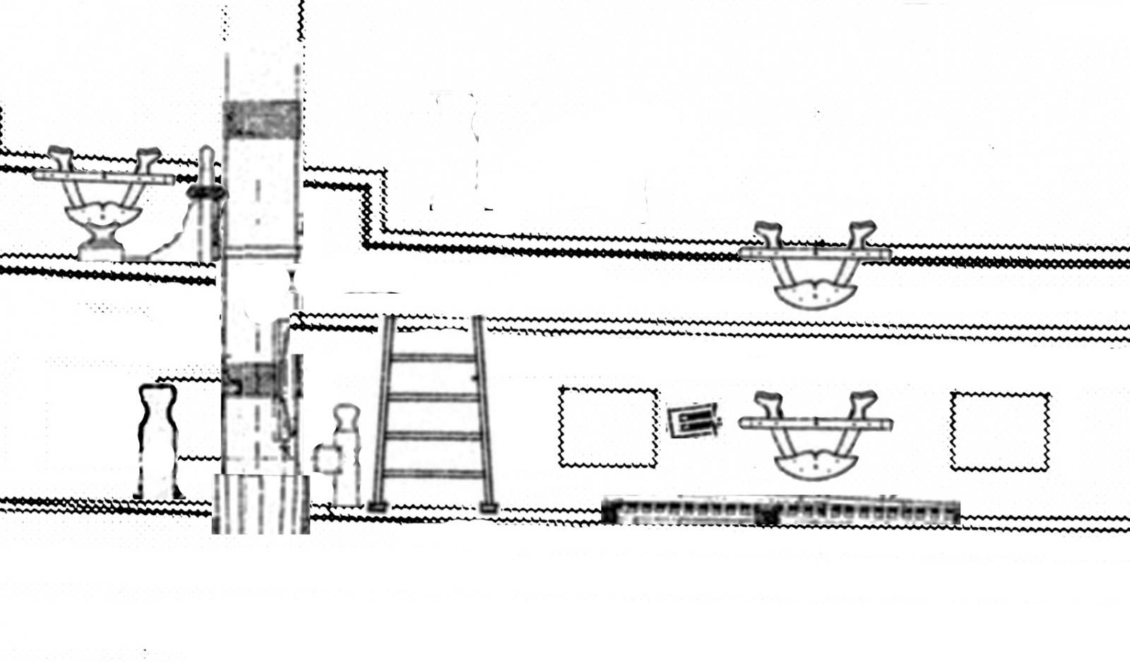
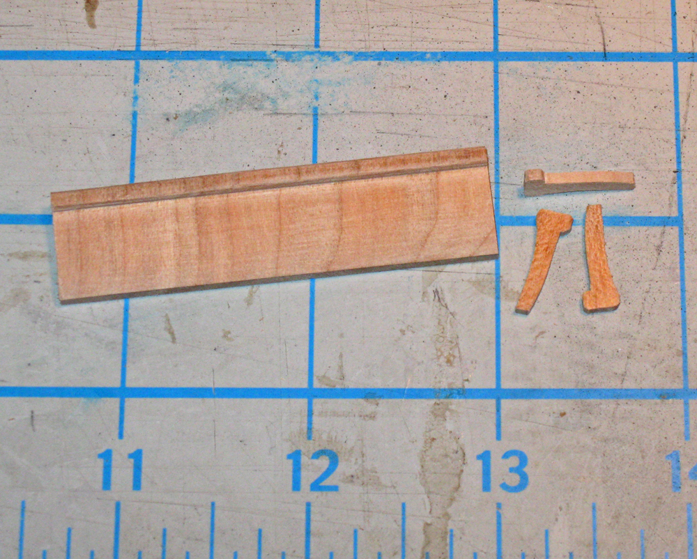
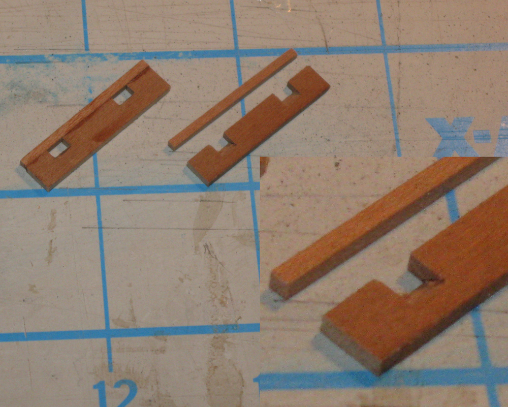
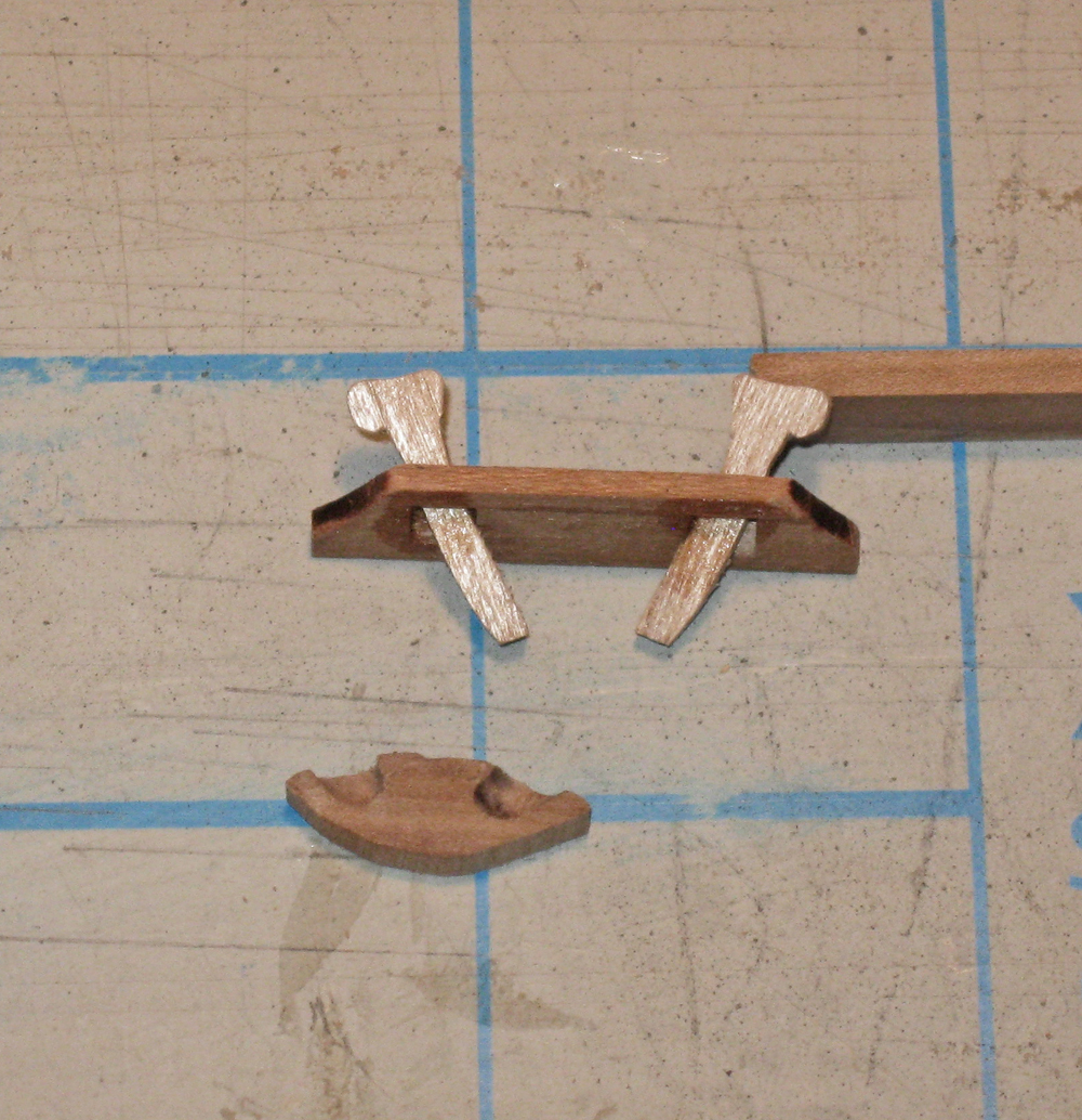
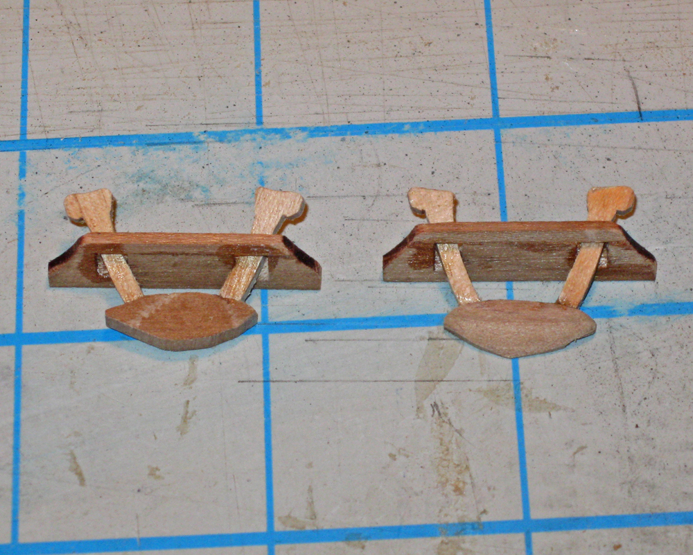
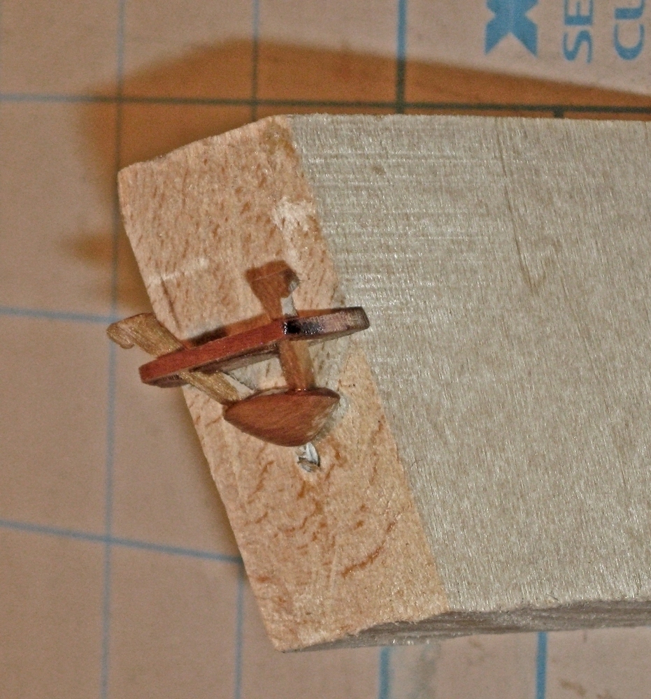
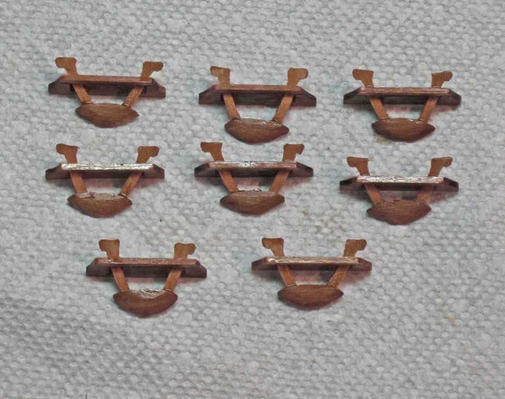
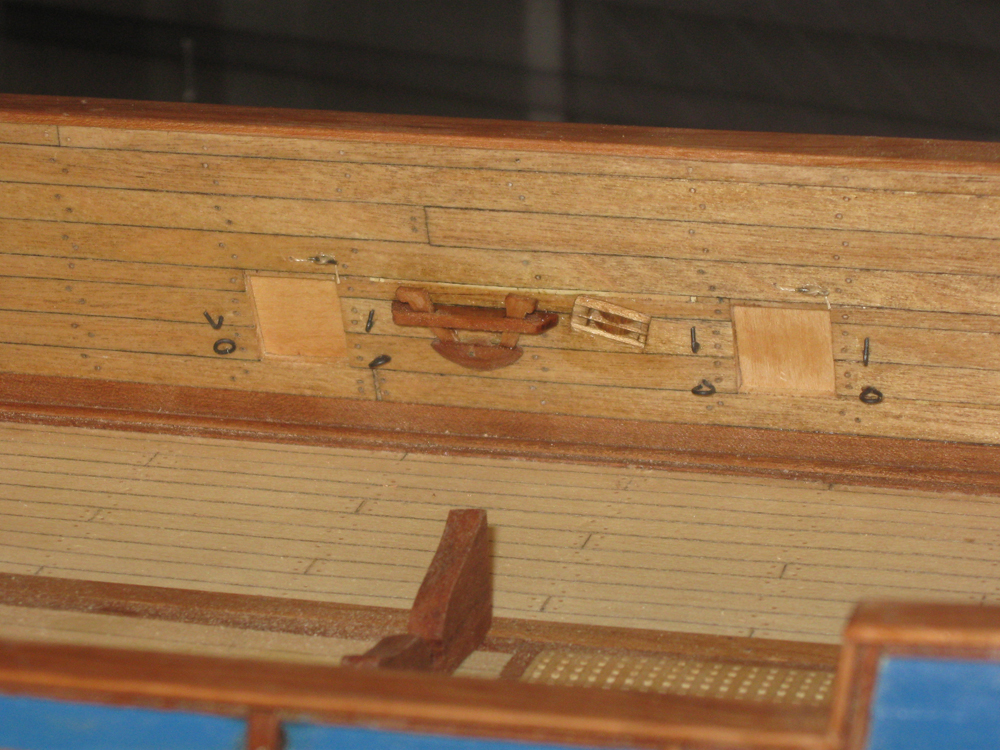
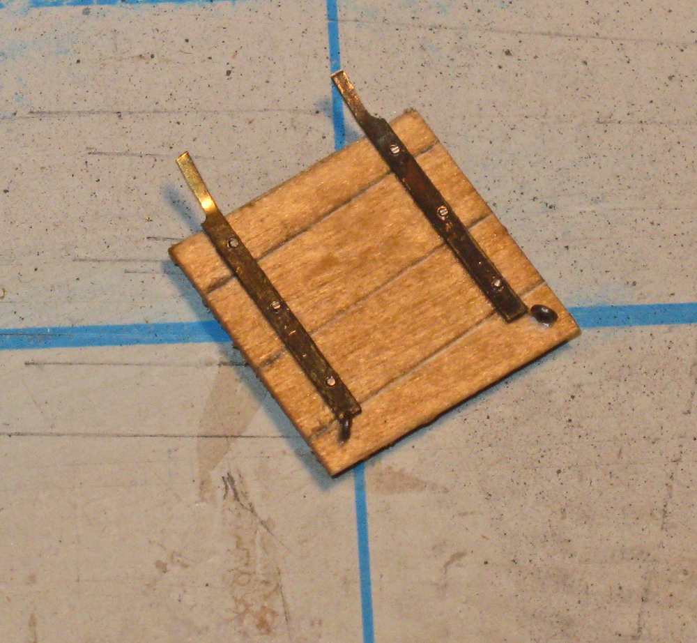
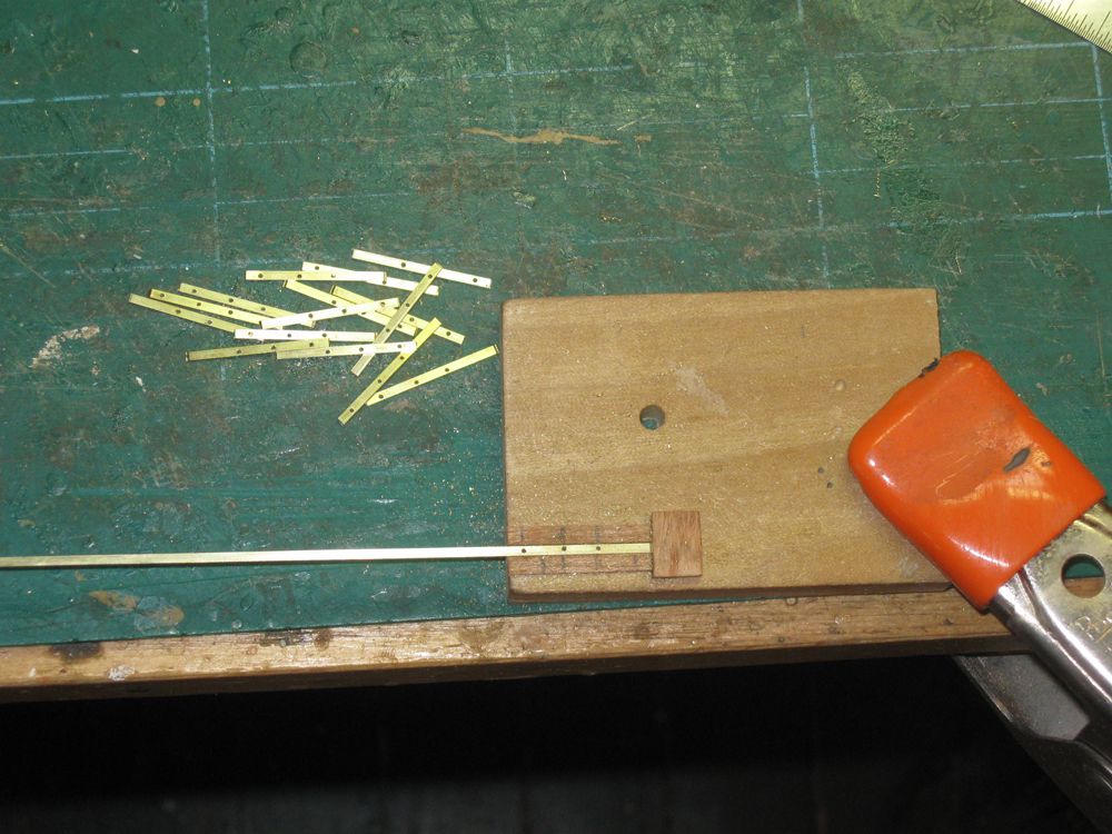
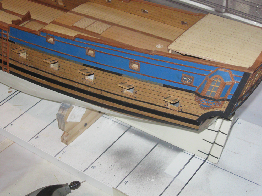
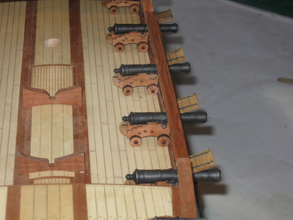
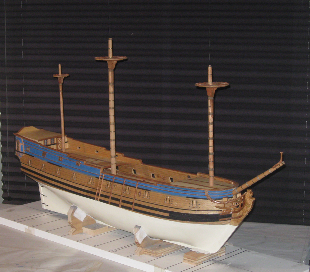
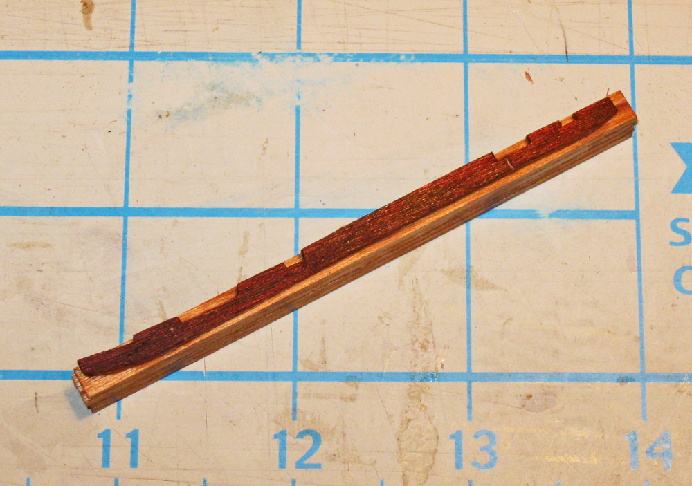
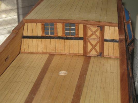
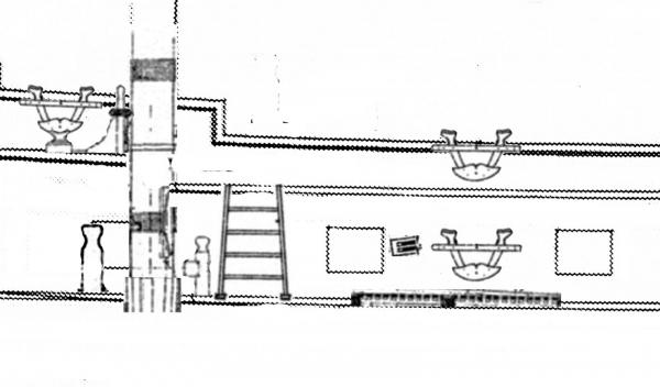
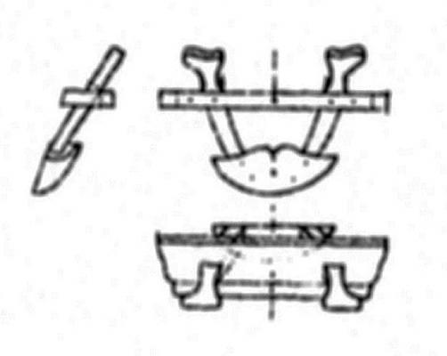
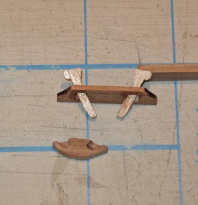
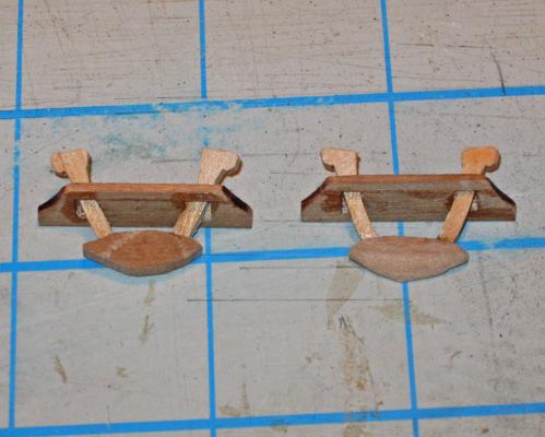
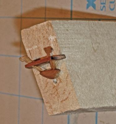
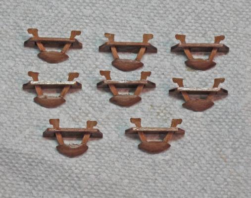
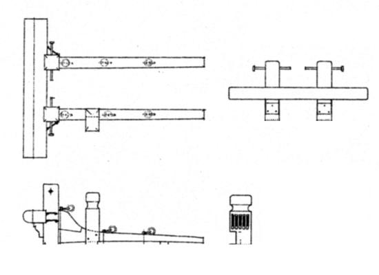
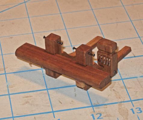
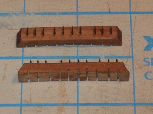
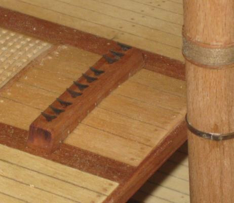
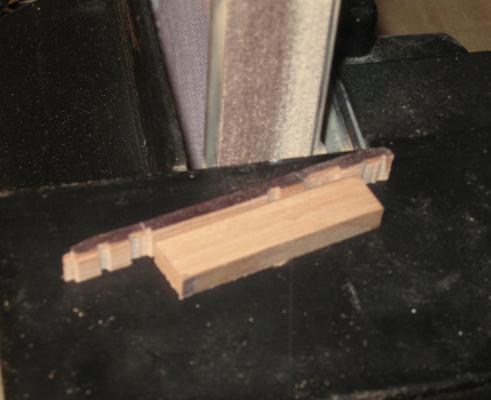
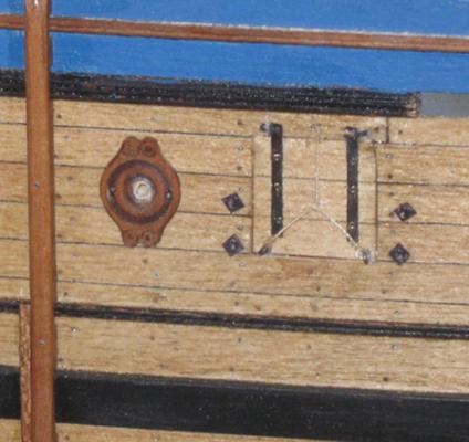
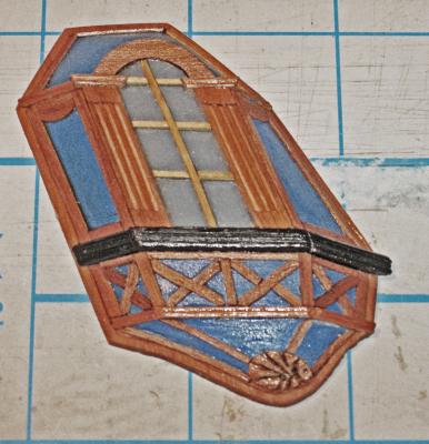
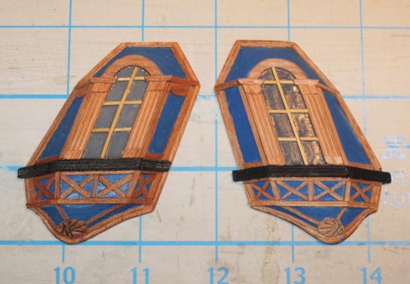
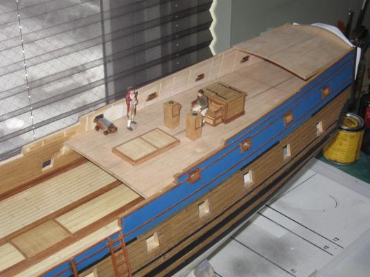
Hi again, and best wishes for a happy Friday the 13th – Thanks for the compliments, likes, and wishes for my new grandson. Caleb and his mother are both doing well and send their thanks as well. Several smaller items were completed in this segment. The first was the forward bulkhead for the captain’s cabin. There are no plans or drawings of it in either of the plans that I am using, so I designed it to be functional, using some of the same details as on the stern and quarter badges. There is a chair rail molding with wainscoting below. This was not scribed but laid up from individual planks. The door is of a typical 17th Century style, with H-L hinges and decorative cross banding. The windows are flanked by fluted columns which were built up as before. To each side there will be a ladder to the poop deck, which have not yet been constructed. The bulkhead is still removable at this stage, and may have to be moved back a little to give me room to install the whipstaff which will go between the cabin and the mizzen mast. I have not decided whether to paint the wainscoting blue and add some decorative details. What does the group think? The cabin was also dressed up by closing in the aftmost gunport with a decorative shutter. The central circle was made by stiffening a 1/8” birch dowel with a drop of thin cyano on its cut end. When dry the center of the dowel was drilled out to a depth of about ¼” and then the circles were parted off on the table saw. Next I turned to the first of the rigging fixtures – the staghorns. Here is a section of my plans for the inner bulwarks, which was made by using PhotoShop to combine the plans from the Advice Prize with details from Le Mercure. You can see three of the four staghorns that will be mounted on each side. Here is an enlargement of the plans for the staghorns. Note in the side view the extreme angles that have to be used to match the 13 degree tumblehome of the bulwarks. I started by carving a length of pear to the shape of the horns of the fitting. The piece was just under 3 inches long, which gave me extra material for the next model as well. Here you can see three horns that have been parted off. They are a little heavy, but were later reduced with a small sanding drum. The shelf that supports the horns was built up in two parts. In the larger, back piece, two notches were nibbled out for the horns before being closed in by the front piece. In the insert enlargement you can see how the curve of the table saw blade gave me an angle to the back of the notch that is needed to allow the horns to angle to match the tumblehome. With the horns inserted in the shelf the bottom piece had two notches hollowed out in its back face for the lower ends of the horns. The lower piece was flipped over and the horns glued into the notches. The lower piece was then sanded to its clamshell shape and the upper ends of the horns were refined to angle up and out. You can see the differences from the left fitting to the completed one on the right. Here you can see a finished staghorn sitting on an angled scrap block to check that the shelf will be horizontal when mounted on the bulwark. Here is the complete set of eight staghorns for the first model. And here is the first one mounted in the waist ready for the lines that run through the hull sheaves for the main and spritsail sheets. Next I turned to the gunport lids for the open gunports on the port side of the ship. I have detailed their construction before in the section on the test gun station. This one is for the forwardmost port, which is why the planking runs at an angle to match the hull planking. The hinge straps are blackened brass strip secured with three iron pins. The ends of the strips were ground to about half their width so they could fit into mounting holes in the hull. The strips were all made to a uniform size in a simple jig. A brass strip was trapped between two guides and the locations of the holes for the mounting pins was marked off. Once the holes were drilled the strip was clipped to length at the edge of the jig. I found that without pre-drilling these holes it was nearly impossible for me to drill them cleanly once the hinge strap was mounted on the gunport lid. Each lid was marked for its proper location and the mounting holes were drilled just above the open gunport. With the lids slid into the holes the brass could be gently bent so every lid was at the same angle. This will be a significant advantage once they are permanently mounted, as they will be much less prone to snapping off when I bump into them (which I am sure that I will). Here they are towards the bow - - - And the stern. To check them, I set the guns in place. Here is what they look like in the waist as seen from outboard - - - And along the length of the ship. Finally, the entire broadside. I was happy with the look of the model, so the guns and gunport lids were removed to safe storage until the interior deck fittings are built and mounted. The first of these was the riding bitts for the anchor cable. As you can see from the plans it incorporates the 5-sheave post for the rigging to the ramshead block that raises and lowers the foreyard. Construction was straightforward, with each piece cut and shaped, then notched and pinned in place. The sheaves in the post are non-working, and made by drilling 5 pairs of holes through the post with a 0.040” drill in a miniature drill press. The bitt was then put into a Dremel and the sheave slot between the holes was carved out. Care has to be taken to allow for the right-hand torque of the bitt, but a little practice yields good results. The next rigging fitting that I turned to were the multiple cleat ‘logs’ that sit just aft of the fore and main masts. These were discussed earlier in the build log as well. Construction here was straightforward as well. Once the dimensions were decided, two pieces of cherry were cut and the ends finished with slopes. The underside of each was sanded to match the camber of the deck. Ten slots were cut in the underside for the lines to run through. It is quite probably that these slots would have been radiused on each side of the log so the line would run smoothly under the fixture. The upper corners of the log were eased as well, as recommended by JerseyCityFrankie. Matching photoetched brass cleats were obtained from Bluejacket, blackened and mounted. Here is the one on the quarterdeck aft of the main mast. It looks good as is, although I clearly have to clean the deck which is getting very dusty. Finally, to check that things are headed in the right direction, and to give my spirits a needed lift, I mounted the decks and the lower masts. Hull construction and detailing have taken much, much longer than anticipated, but I can see some light at the end of the tunnel. I just hope that it is not the oncoming train known as “RIGGING”. Be well Dan


- 241 replies
-
- 14
-
-
- queen annes revenge
- pirate
- (and 2 more)
-
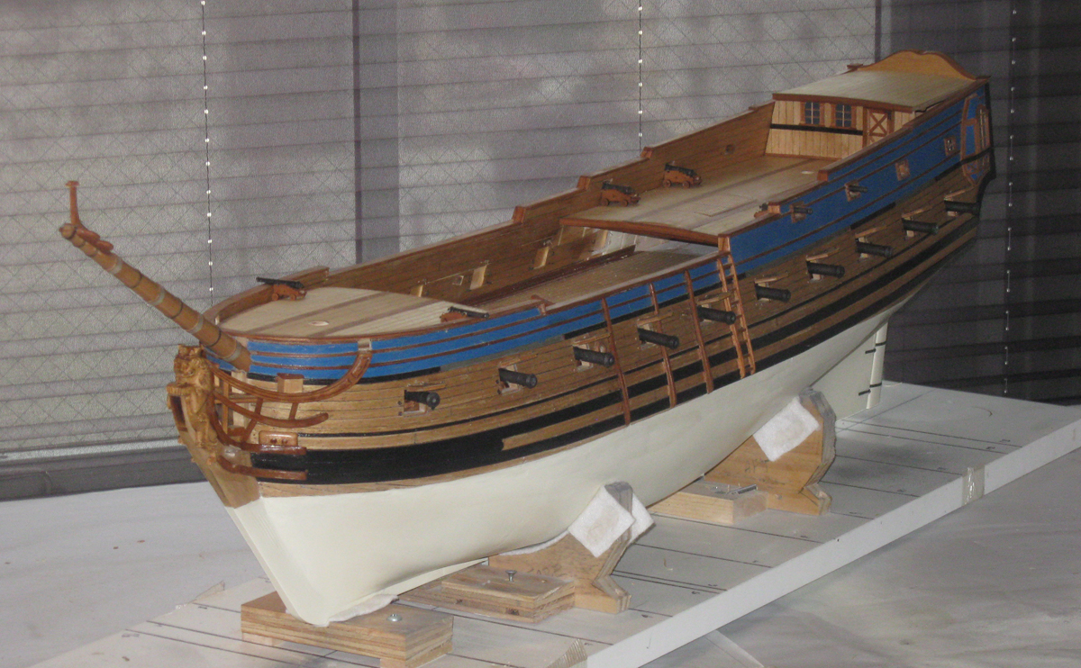
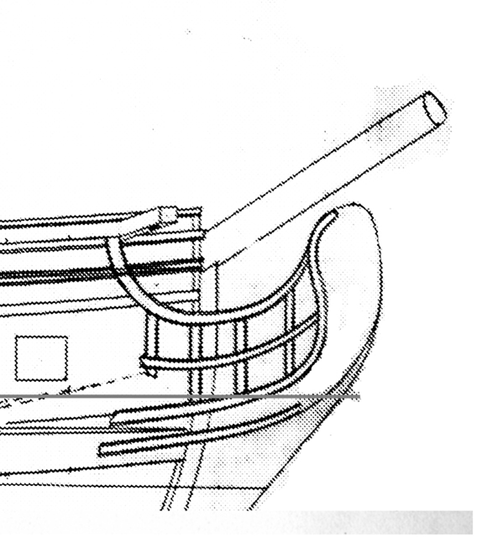
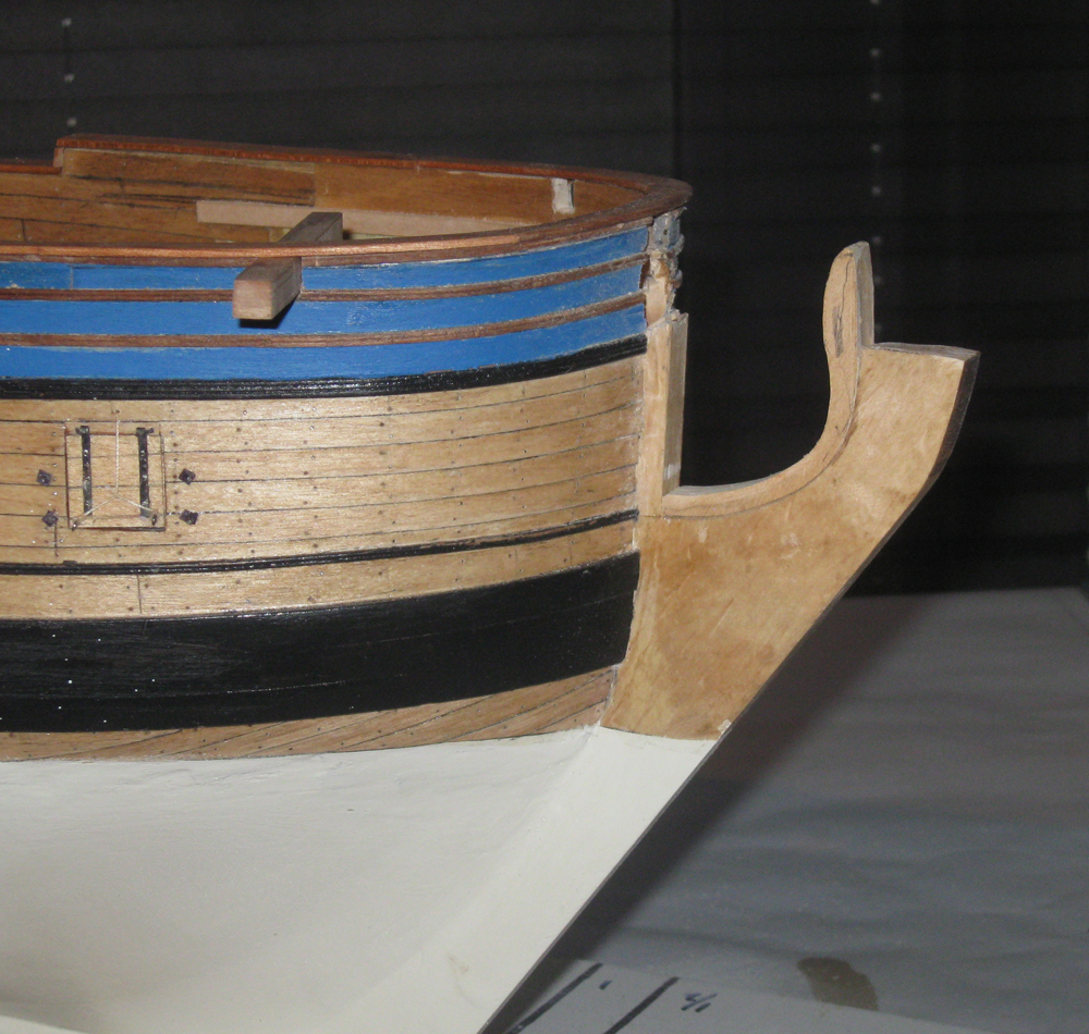
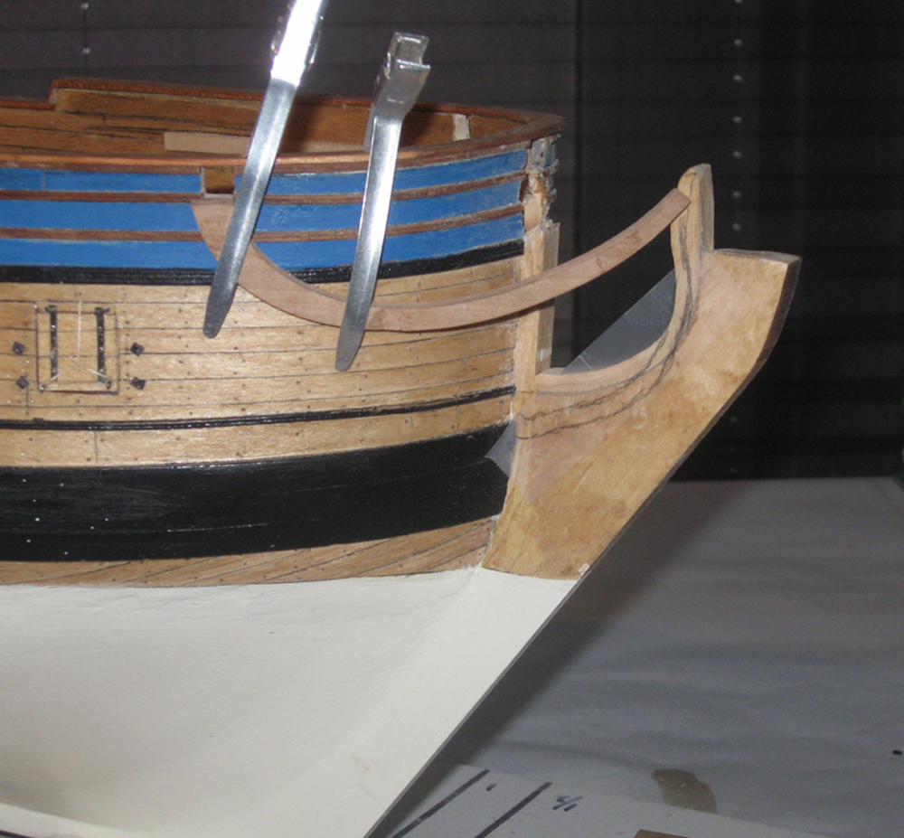
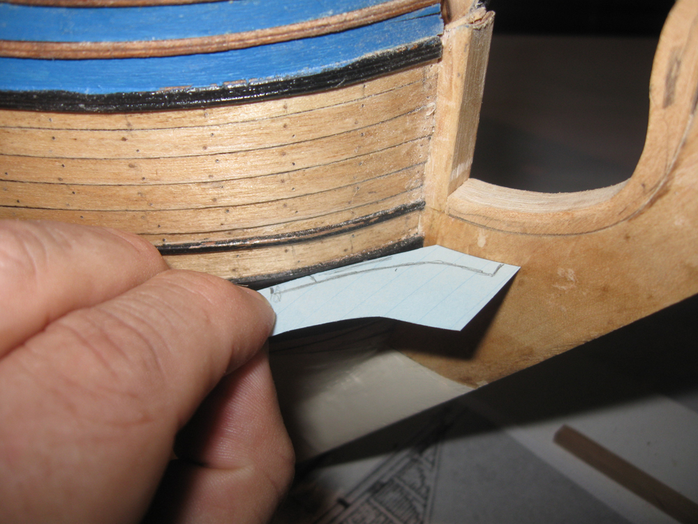
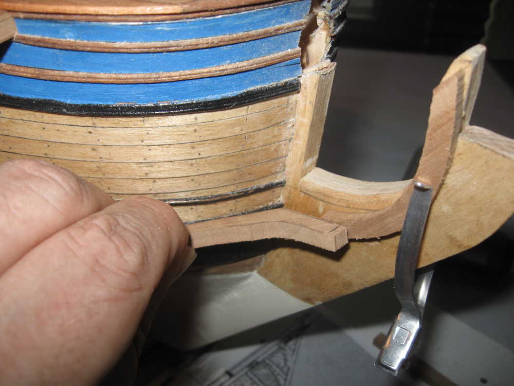
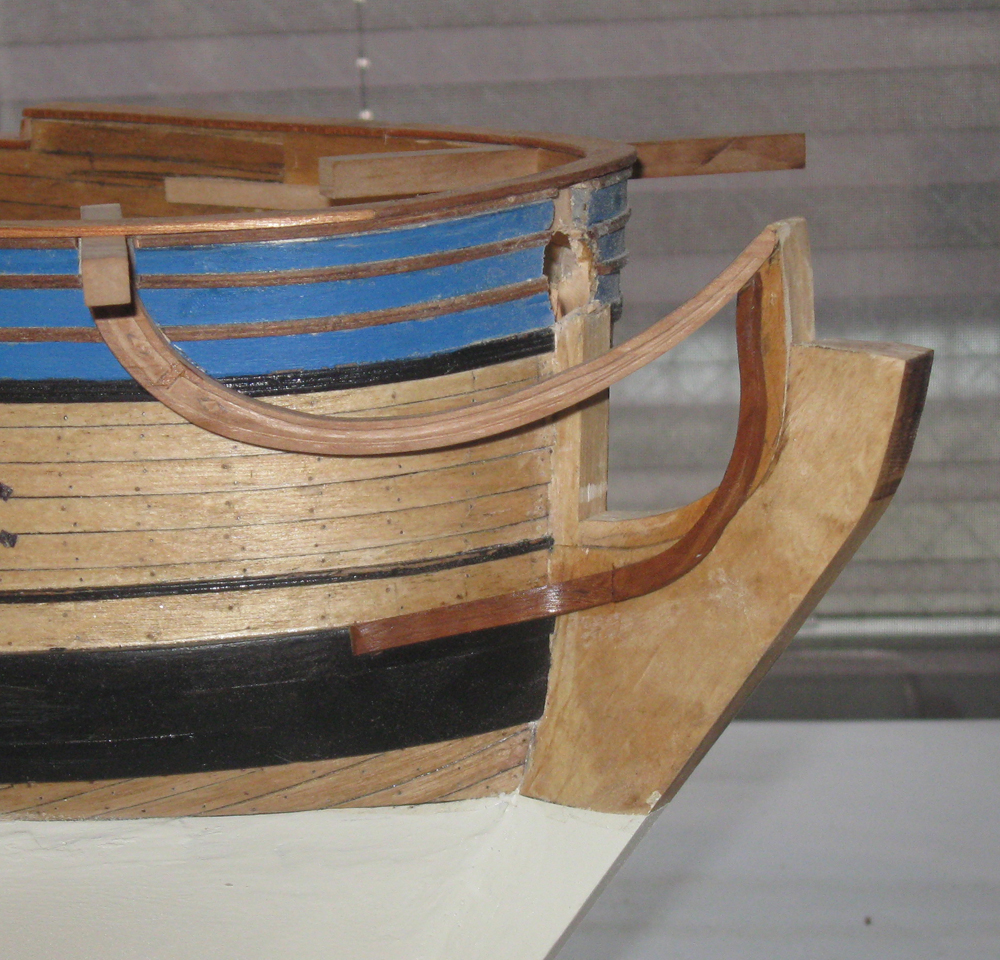
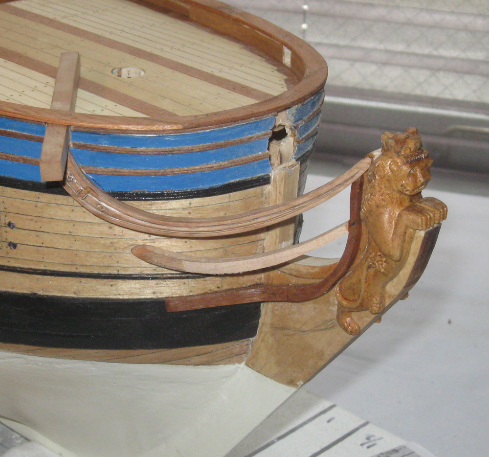
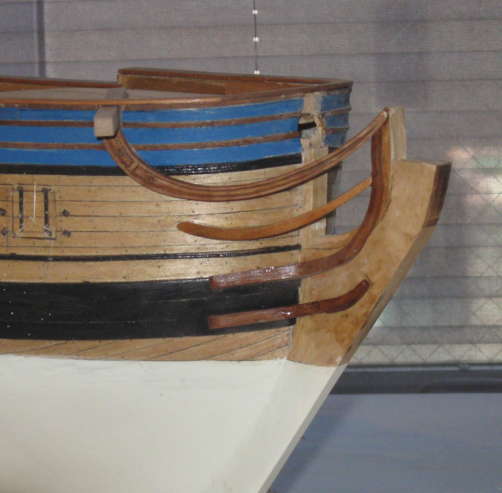
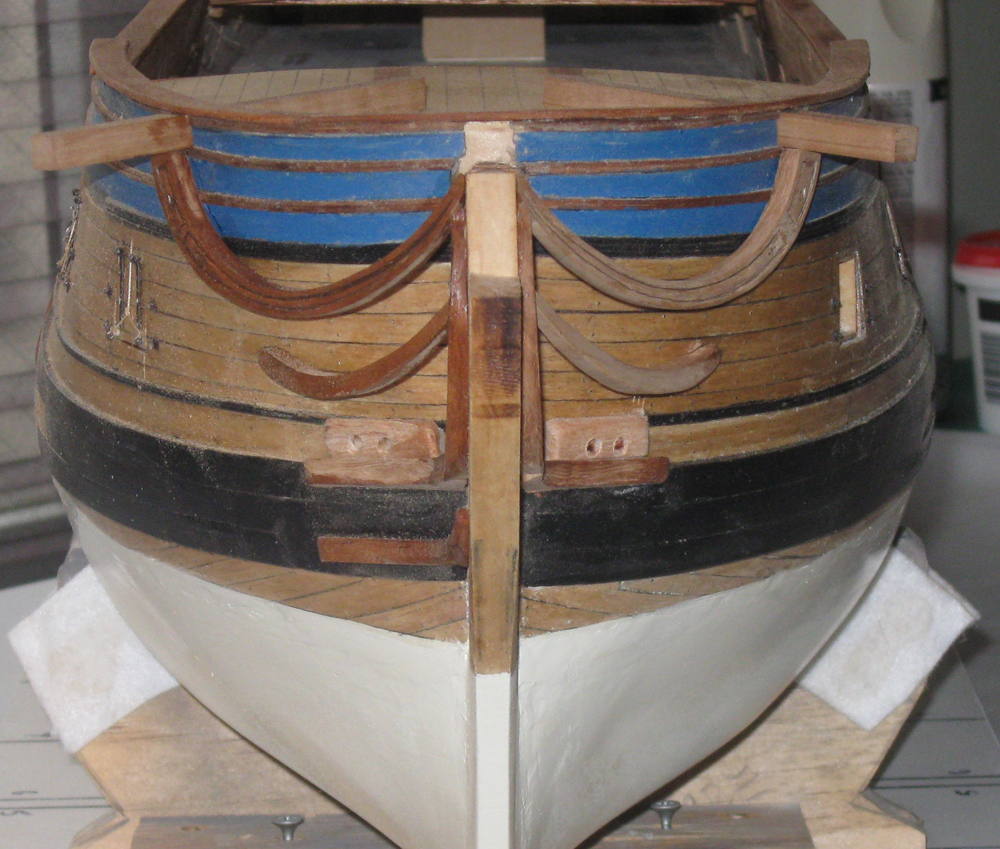
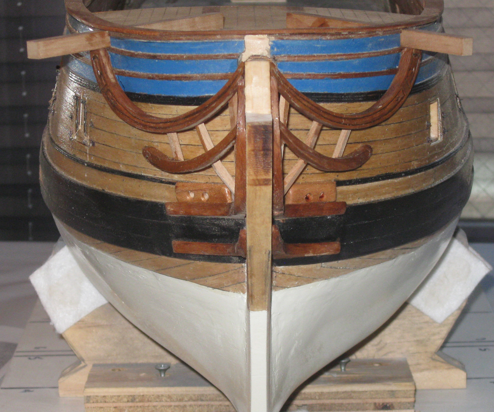
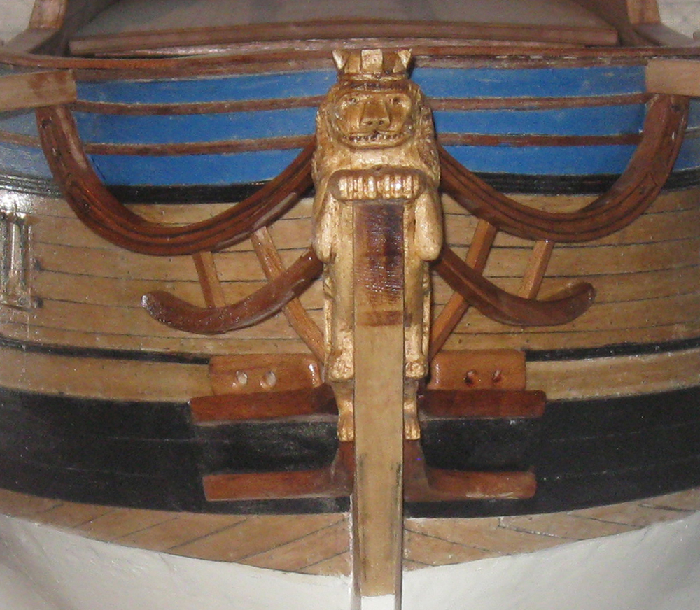
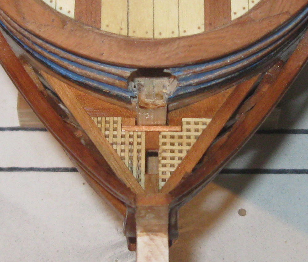
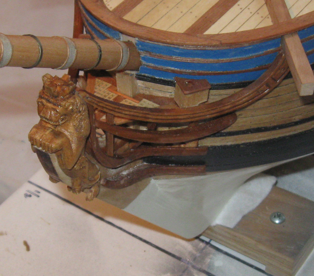
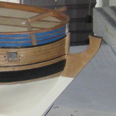
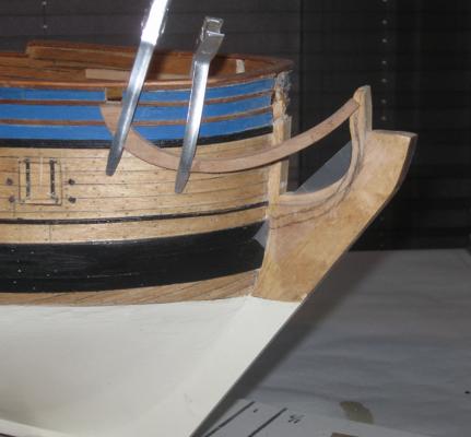
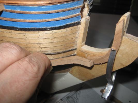
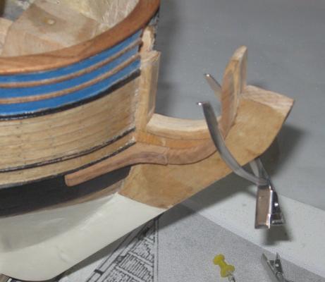
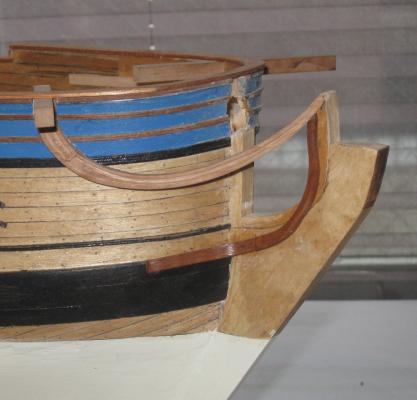
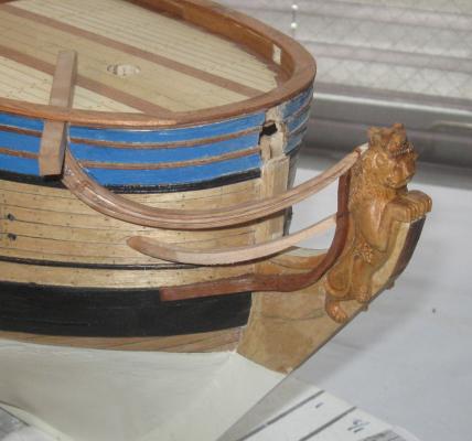
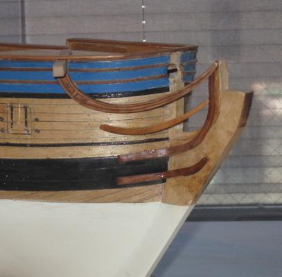
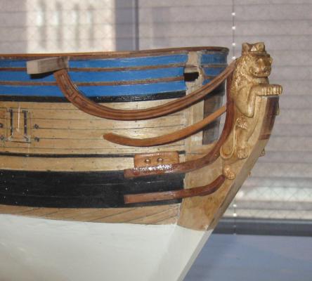
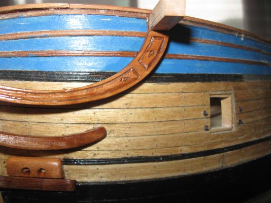
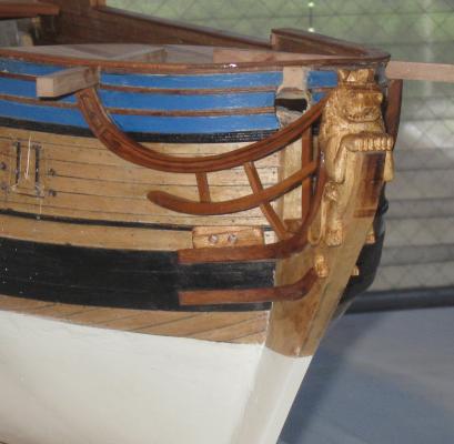
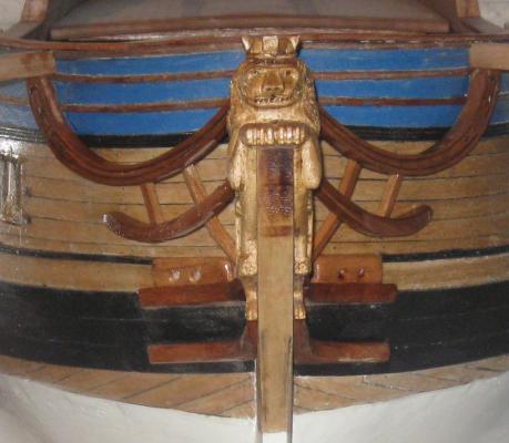
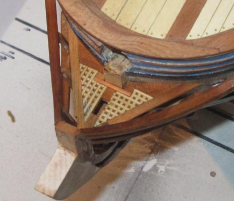
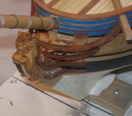
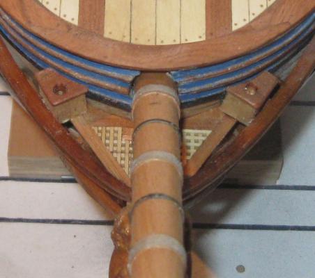
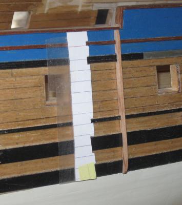
Log 24 - Head Structures Hi again. It has been a bit longer since the last segment than I hoped, in part because our daughter gave birth to her second child and our eighth grandchild. Everyone is doing fine and it reminds me that there is more to life than ship modeling. Sacrilege, I know, but it’s hard to deny. Time to concentrate on the head structures, the rails, supports, and small deck that fit around and under the base of the bowsprit. Here is how they look in the plans. I started with the bare stem piece cut off at the approximate height to mount the figurehead. It had been left somewhat rough to this point before the rails were fitted. The stem was trimmed flat and the inside curve was sanded smooth. A strip of hardwood was cut and fitted to the inside curve which extended up to the height of the lion figurehead’s mane. It will support the forward ends of the two upper rails. The edge of the mane was penciled in on the wood for reference so the rails don’t interfere with the figurehead. The top rail was roughly shaped to fit from the cathead to the stem in a pleasing curve that matches the plans, but it was not finished at this point. In the photo you can see a piece of translucent tape which has been laid on the stem so the ‘S’ shape of the lower rail could be drawn on it. I call this rail the ‘hawse rail’ because the hawse piece mounts just above it and I don’t know its proper name. The hawse rail is made up of two pieces. Here a paper pattern is being developed to establish the mating faces of the lower section against the wale and the stem. The lower piece was cut using that paper pattern while the upper section was cut using the tape pattern with the shape drawn on. They were both left a bit oversize to allow for a good deal of shaping and fitting. Here they are roughly set in place. The lower piece was ground and sanded till the mating face was flush with the wale and the piece sat at the proper upwards angle to meet the descending angle of the upper piece. The outer face of the lower piece was left large till the upper piece was fitted. Here you can see the hawse rail fitted, sanded and given its first coat of finish. The upper rail has now been shaped to fit. Simple carved decorations give the upper rail some interest. A better photo is coming later. With these two rails in place the middle rail was fitted, shaped and installed. The figurehead was repeatedly put on to test the fit of the rails then removed for safety and to provide clearance to work on the rails. The bottom rail was built up in two pieces like the hawse rail. It is just a lot shorter as it extends only to the foot of the lion. Here are all the rails as fitted and finished. Now the hawse piece was cut and fitted to the top of the hawse rail. Two holes were drilled for the anchor cables to be installed into when the time comes. Here they are with the figurehead in place. The carvings on the top rail can be seen clearly in the photo. They were done with a sharp-cornered bit in the Dremel, then smoothed and refined with a curved file called a riffler. The varying shine on some of the parts will be toned down and corrected in the final finishing coats. As I was roughly cutting out the rail pieces, I made a second set for the port side. All of the techniques were the same. Here are the port side rails, except the bottom one. I was fortunate that prior planning made it relatively easy to get the two sides symmetrical. And here is a detail photo of the rails and the carvings on the port side. Three support brackets were fashioned and installed between the upper rails. Only the middle one had to have a bent shape to lie against the rails and sit next to the hawse pieces. Here they are installed but not finished. And here they are finished in two views. The end points of all the rails and the intersections with the support brackets were all subsequently reinforced with metal pins and glue. Next the deck and grating under the bowsprit were built. A paper pattern was used to define the total size and shape of the piece so it sat level and firmly on the rail support brackets. It was built up from two triangular pieces of grating, with solid pieces fit around it and against the curve of the hull. You can see in this view how a hole was left along the centerline for the gammoning which will hold down the bowsprit. Two seats of ease were fashioned from solid birch pieces with cherry tops. The bowsprit has been temporarily installed to check the fit. A wooden ring, like a mast coat, will dress up the entry into the hull when it is permanently installed. You can see a small mark on top to locate the central gammon cleat later. So here is the completed head structure. There will be a wire railing installed for the safety of the crew while using the heads, but that will wait until the gammoning is installed so it does not interfere with my stubby fingers as I work. Next on the schedule – the captain’s cabin, the open gunport lids, and the channels and deadeyes. Hopefully it will not be so long till the next report. Be well Dan


- 241 replies
-
- 10
-
-
- queen annes revenge
- pirate
- (and 2 more)
-
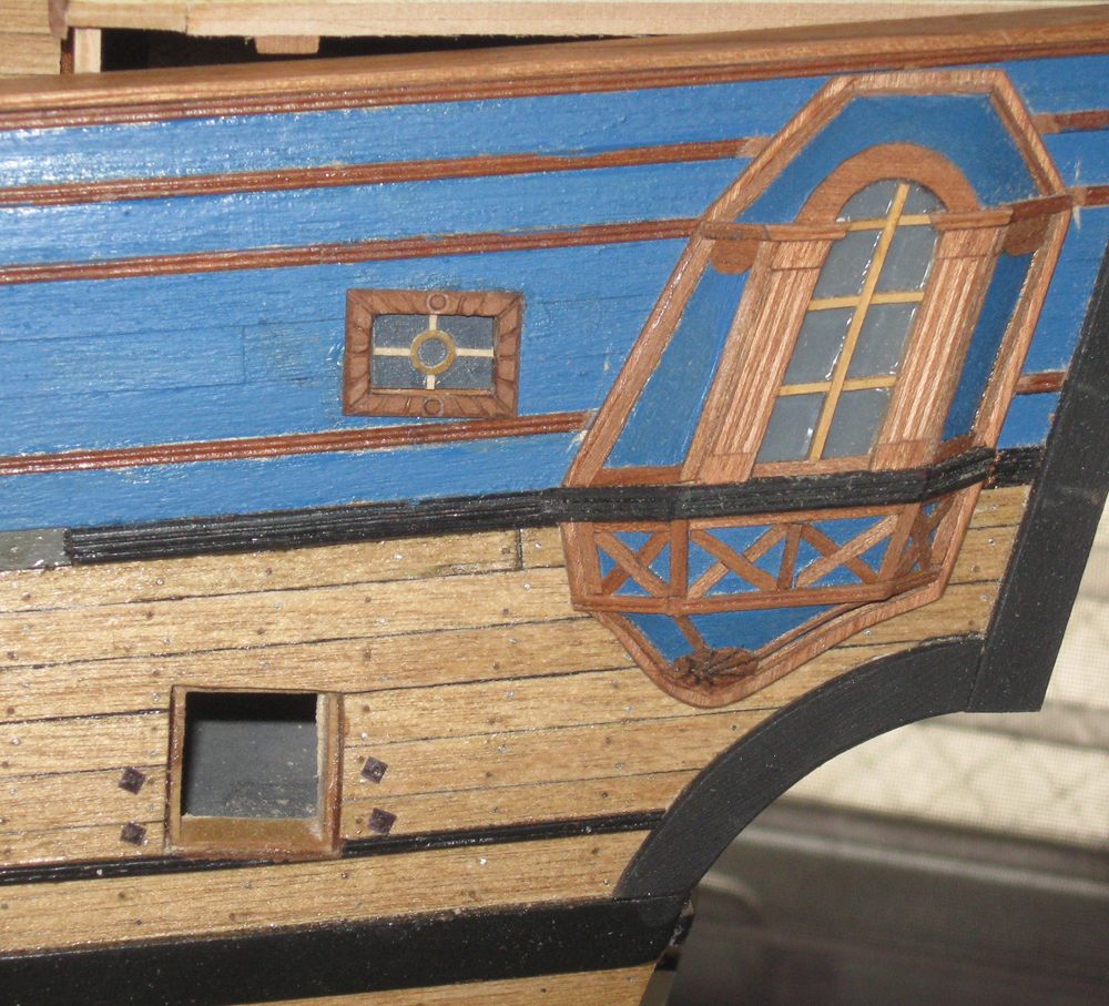
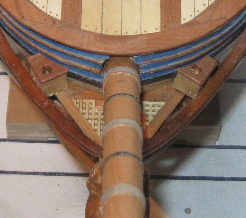
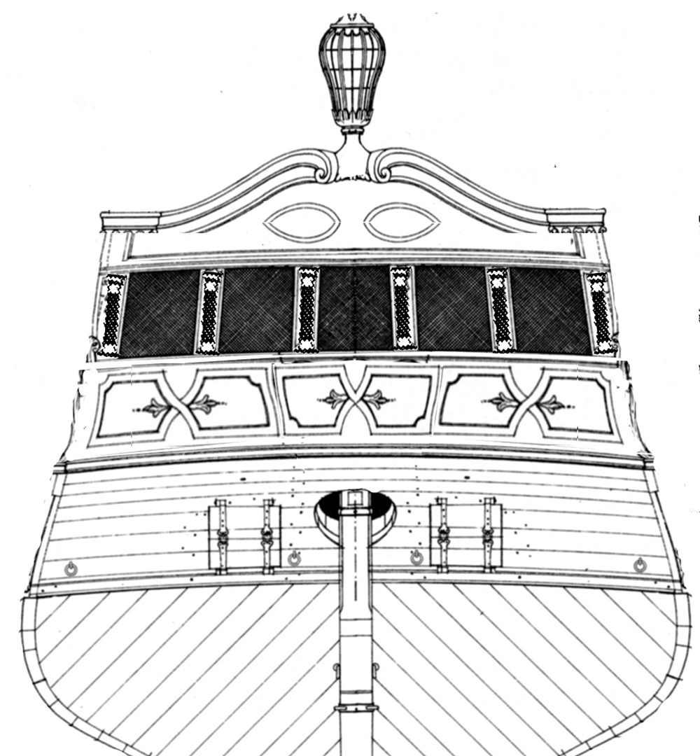
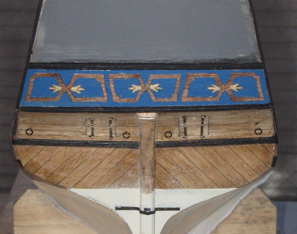
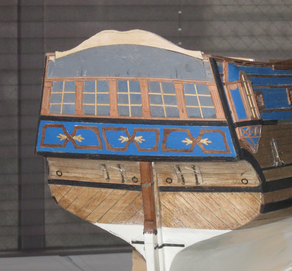
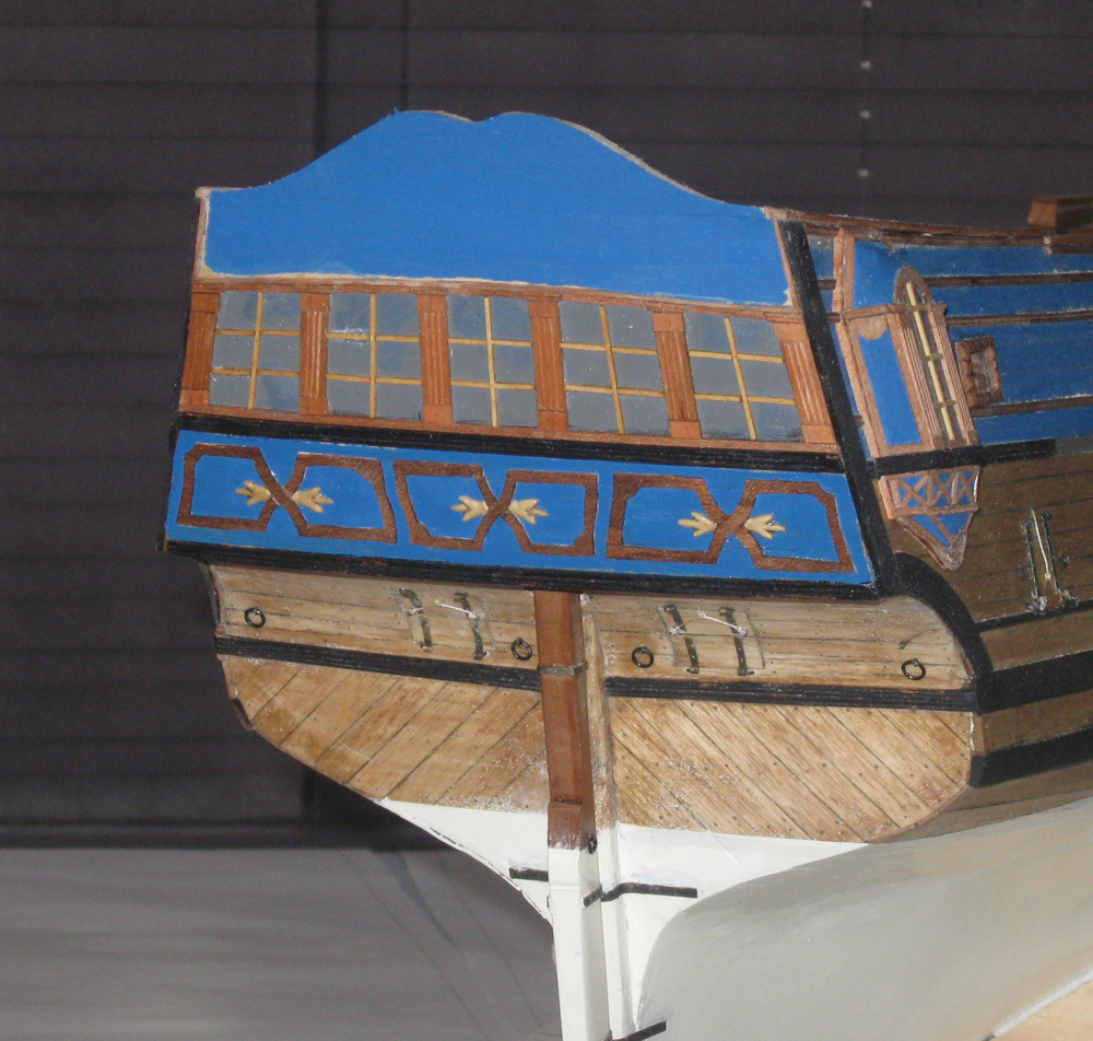
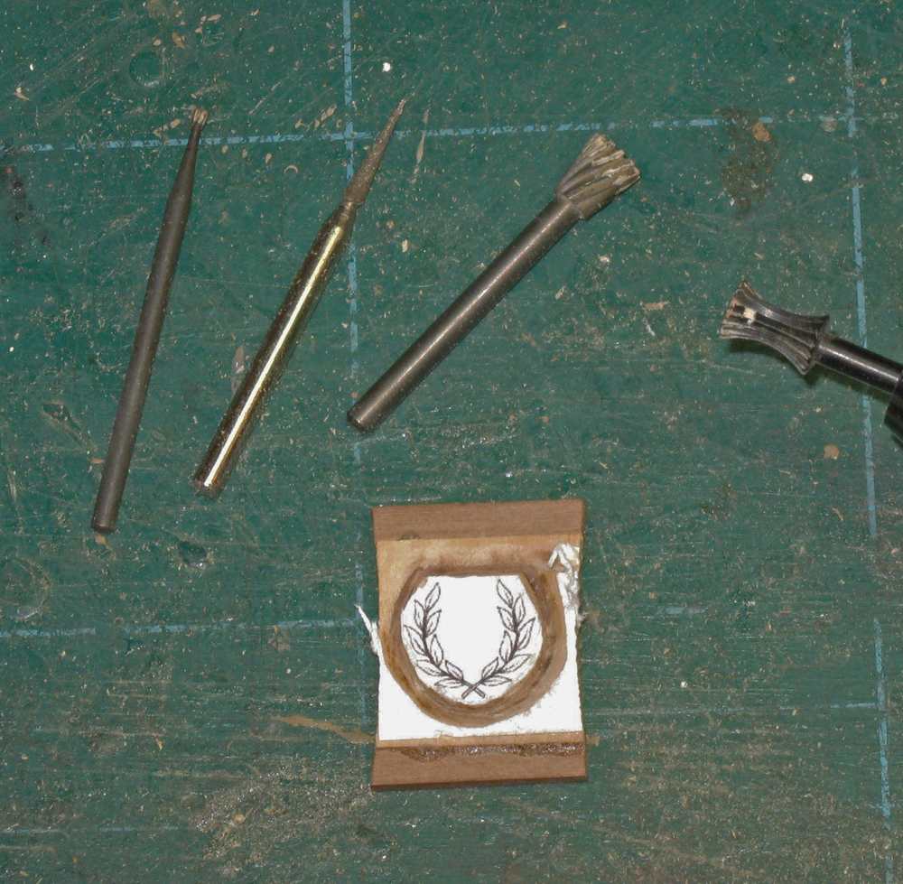
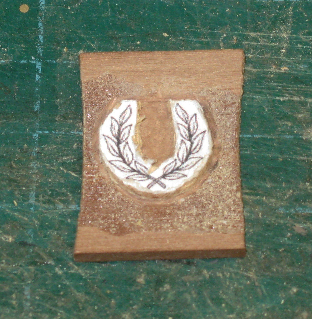
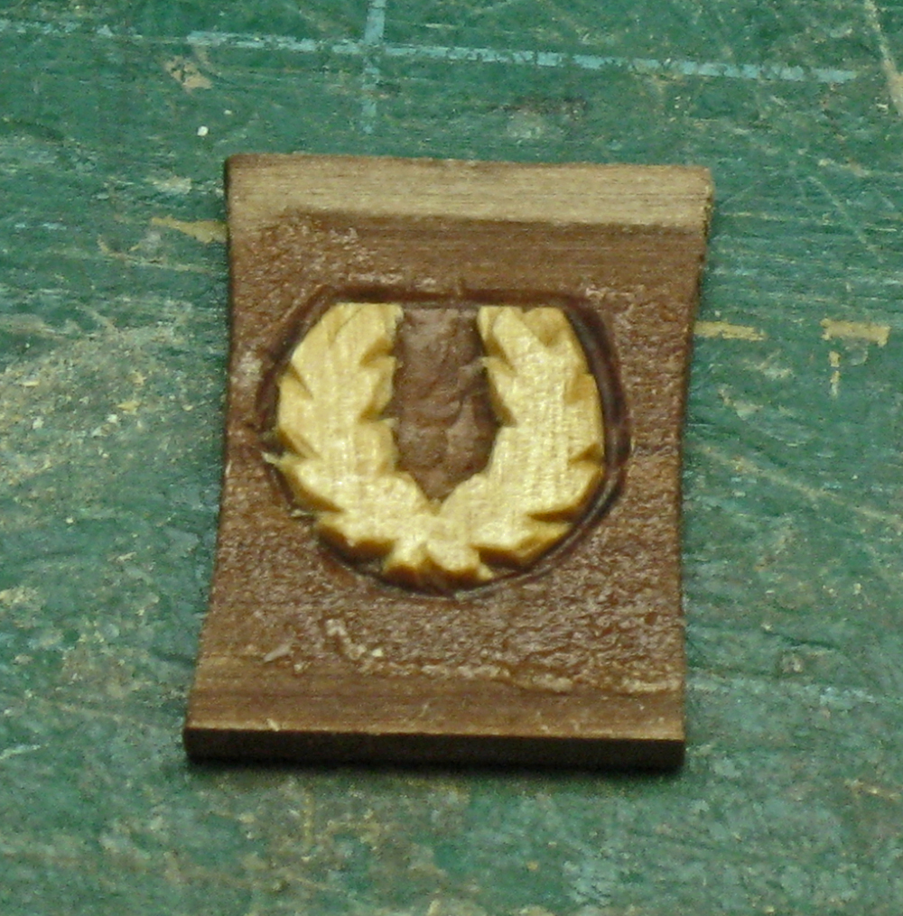
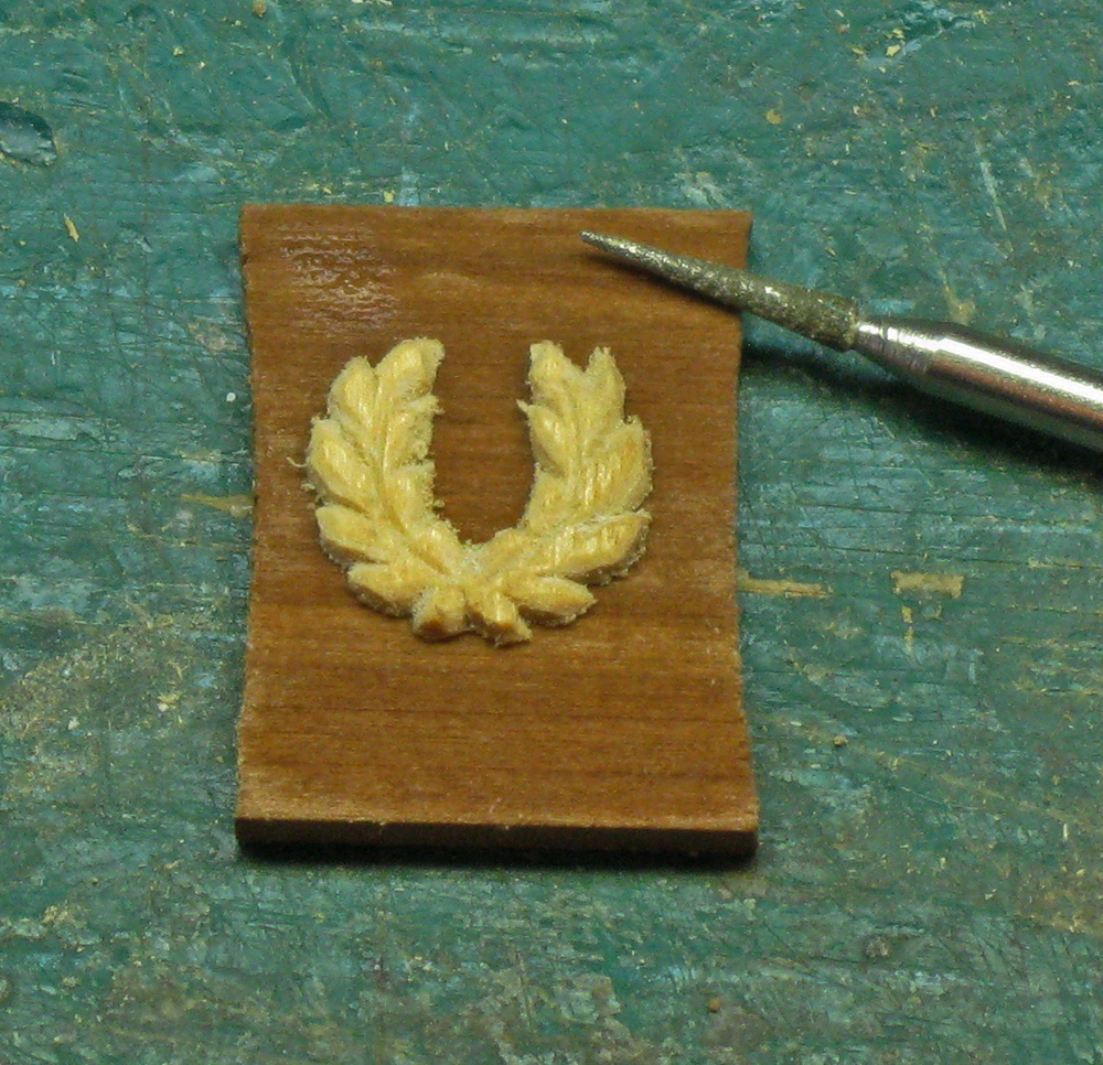
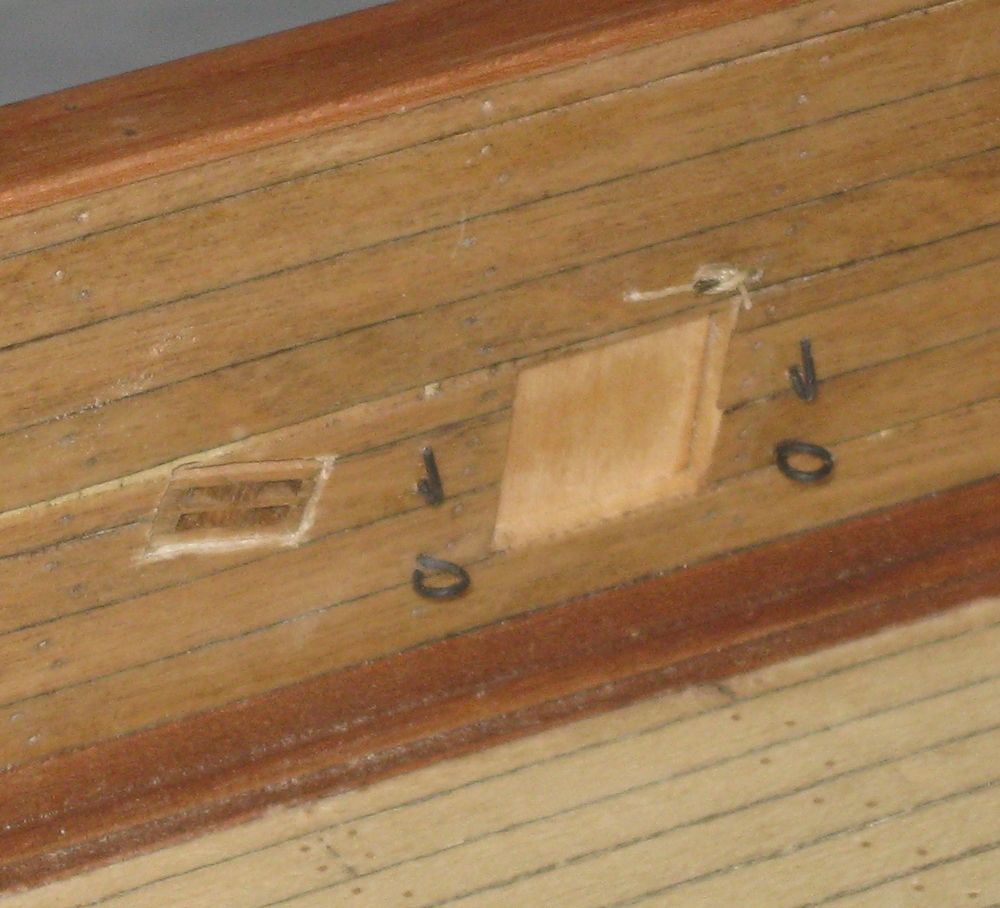
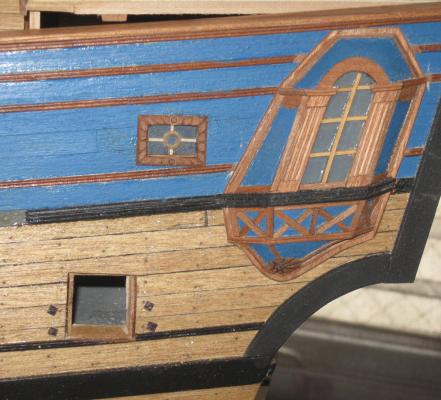
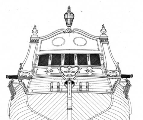
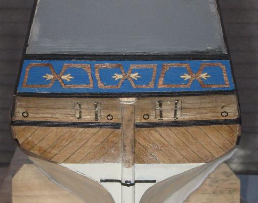
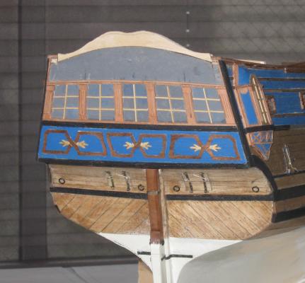
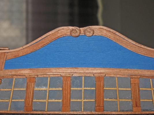
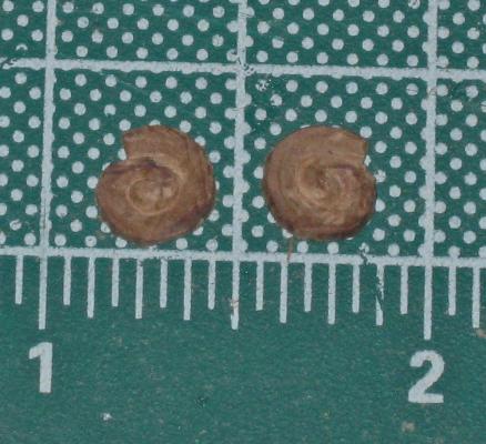
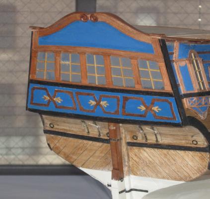
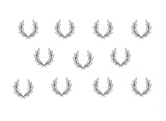
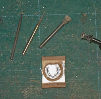
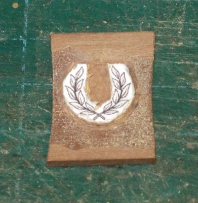
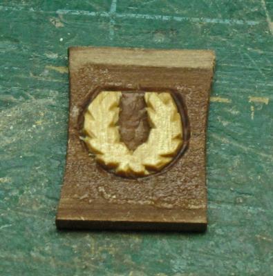
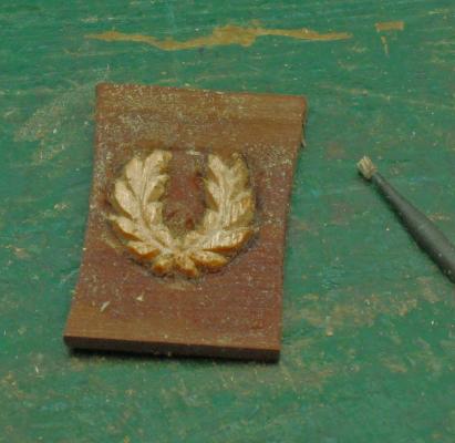
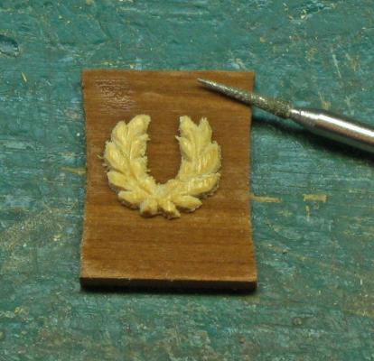
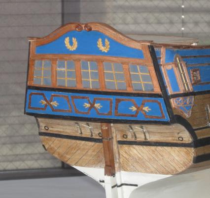
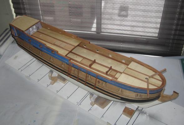
Hello again – I have just completed the construction of the stern, which was complicated enough to merit its own log entry. The design is a bit of an exercise in imagination, without any hard facts to go on. The Advice Prize draught has no information at all; the stern outline is shown as part of the station lines plan, but without any decorations or indications of the shape of the counter, transom or even the top of the taffrail. Budriot’s drawing of the stern of Le Mercure is excessively florid, with lots of carvings, an intricate nameplate, and even flaming finnials at the upper corners of the taffrail. Not only is this much too ornate for the QAR (and for Le Mercure, which was a merchant ship), but the heights of the windows do not match the deck heights taken from the Admiralty draught. After playing around in Photoshop for a while a simplified layout was designed with many of the same elements that went into the quarter badges. This was passed before my masters and approved. The first section worked on was the lower transom just above the counter. The wide moldings were set matching the locations of the similar ones on the sides of the hull and the field between them was painted blue. The decorative boxes were taken from the plans and cut from cherry veneer. Wood glue was sparingly applied and they were taped down until solidly attached. The light colored ‘flowers’ were carved from 1mm boxwood. They do not appear to be fleur-de-lis, but I could not make out any further details in Budriot’s drawing. Above the top molding were the windows in the captain’s cabin. There is no false light in the center because the rudder head ends in the gun deck below the cabin. The field was painted grey and the moldings, fluted columns, and capitals were cut and applied using the same techniques as for those on the quarter badges. There are six columns framing five windows. I did the two outermost ones first because they have the biggest angle to vertical. Then the remaining area was divided into five equal spaces and the central two columns were mounted vertically. The last two were fit by trial and error to sit halfway between the inner and outer columns. They were cut and recut several times until I was happy with the look of the windows that were formed. As before, the windows were glazed with white glue that was painted on. While it was tacky the mullions were cut from birch and laid in. At the top of the taffrail you can see the added piece of basswood that was cut and fitted to give it the double recurved shape from the plans. The joint was filled and sanded and the field was painted blue Moldings were pieced together above the windows and along the sides. At the top, sections of molding were steam bent to the curves and attached. Ribbons of cherry veneer were shaped to the curves of the moldings and edged with a thin molding strip. In the center a pair of volutes (similar to fiddleheads) were carved and applied. The volutes are a little intricate, but I got a lot of help from the illustrations in “Carving Figureheads & Other Nautical Designs” by Alan & Gill Bridgewater. If you can picture a snail shell seen from the side, that’s what they look like. The stern was now complete, but the upper area cried out for some sort of contrasting decoration. I could have made simple circles, like those on the Mercure drawing, but I decided to get a little fancy and carve a pair of laurel wreaths, symbolizing victory. I got a simplified image of a wreath off the internet, resized it and duplicated it a number of times before printing. The paper image was cut out and spray glued to a piece of 1mm boxwood, which was itself glued to a piece of dark contrasting scrapwood. Using a sharp cornered bitt, the outline of the wreath was cut through the box until the dark wood showed all around. This left the paper and boxwood standing up from the background ready for detail carving. Using a medium sized bitt, notches were cut to indicated the locations of the leaves, and the paper was removed with a drop of mineral spirits. A smaller bitt was used to define the leaves and cut the indication for the central stems. A pointed diamond burr was used to further refine the leaves and to slope the lower edges so there was some depth to the carving. The burr left some soft and fuzzy edges, so once the piece was separated from the backing piece with a drop of acetone, it was cleaned up with a knife, needle files and a fine sanding stick. Here are the pair of wreaths attached to the model. With them, the stern is now complete. The headrails will be the next area to be tackled. Until then . . . Be well Dan


- 241 replies
-
- 14
-
-
- queen annes revenge
- pirate
- (and 2 more)
-
Hi all - Thanks for all the kudos. I took the time to look at some of the logs that you all are posting and I am happy to be a part of such a talented community. David, Keith - glad to pass along some of the tips that I have learned and the techniques that I have developed. Second only to actuallty building ship models, I like talking and teaching ship modeling. Be well, and happy Mother's Day to everyone out there, female and male. Dan
- 241 replies
-
- 1
-
-
- queen annes revenge
- pirate
- (and 2 more)
-
Sherry - My bad. You would think that I could read the title of your log . . . I have my notepad and I'm really looking forward to seeing your techniques. Your ability to get such smoothness on the central globe surface which is under the raised cross is well beyond my limits. Thanks so much for sharing. And, if it applies for Canada, and for you, happy Mother's Day. Dan
-
Hi Sherry - Beautiful work on the carvings. Are they from the kit or are you scratch-building them? If so, are they carved wood or molded clay/polymer? Whatever they are, you are doing an excellent job with them. As for the vertical pieces, they were skids that protected the hull planking when loading and unloading stores, boats, and other items that got hauled up the ship's sides. Keep up the good work. Dan
-
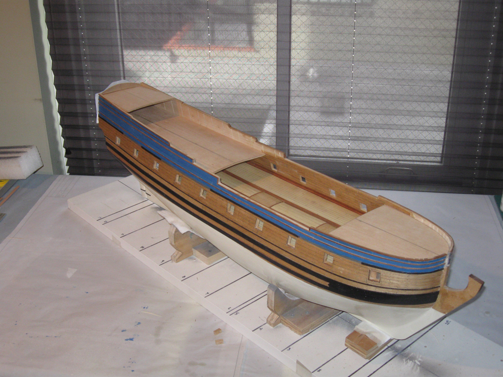
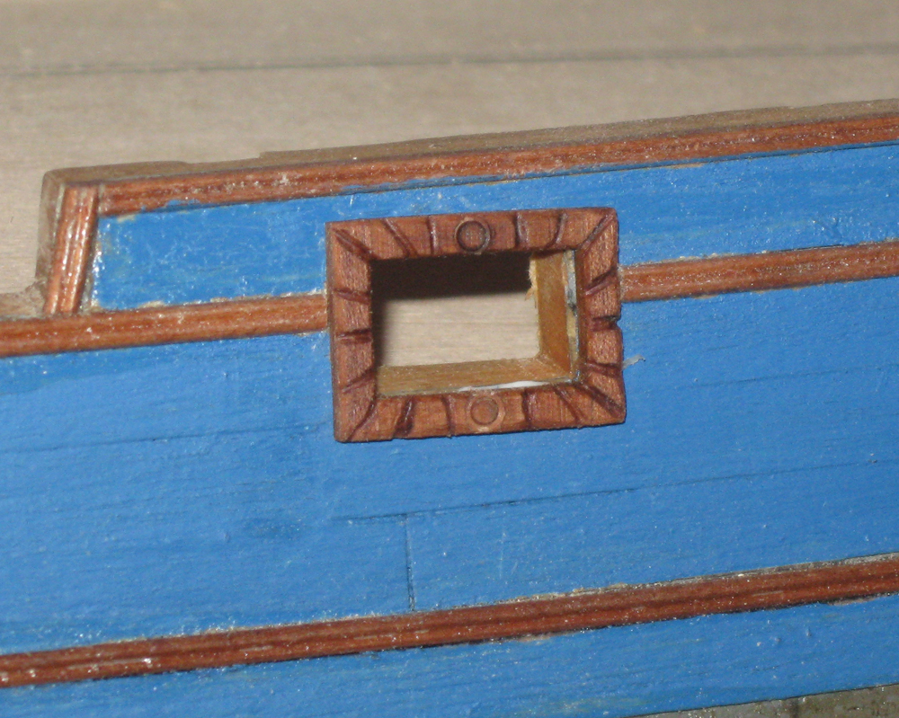
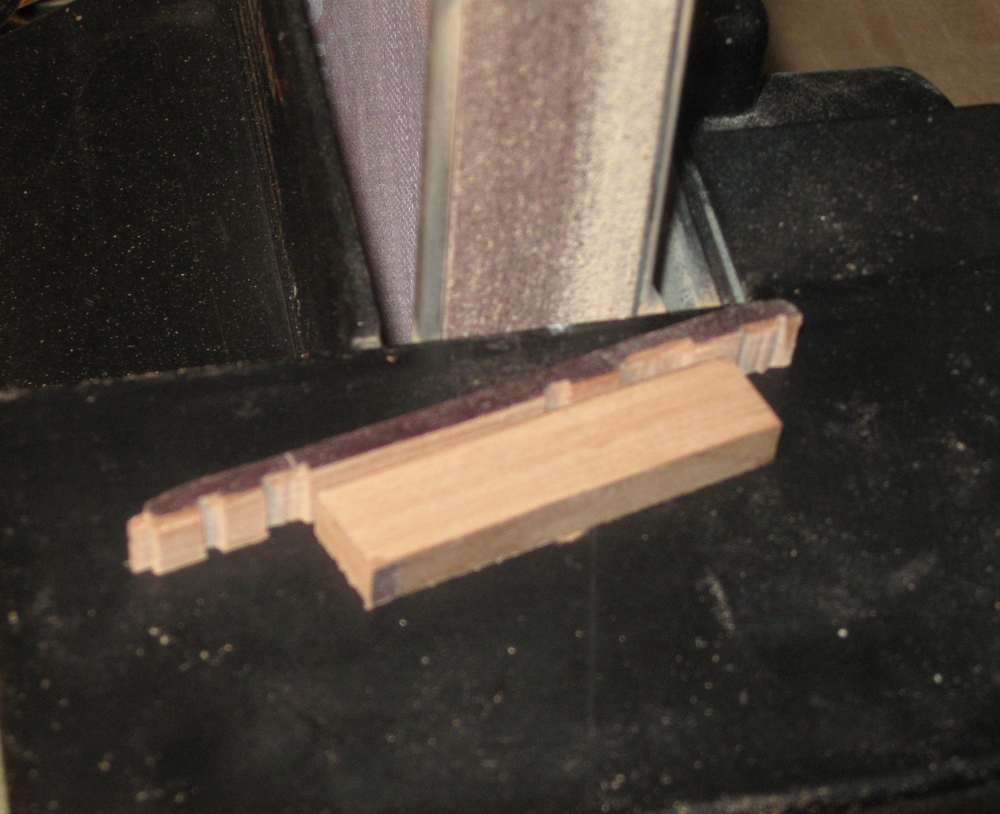
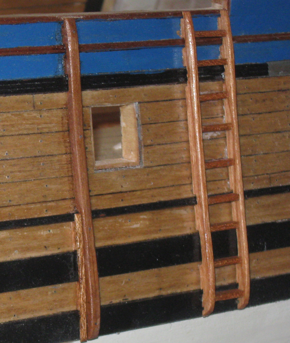
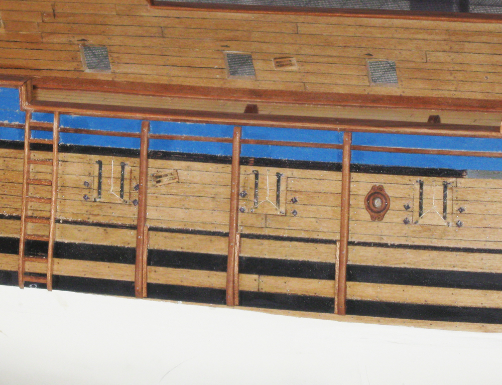
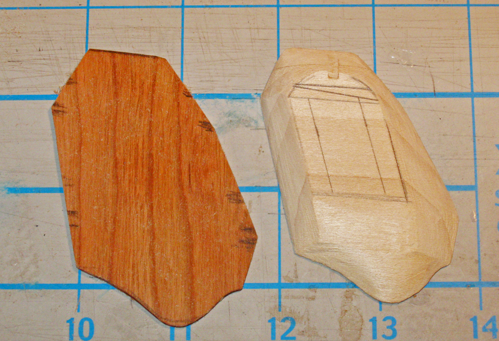
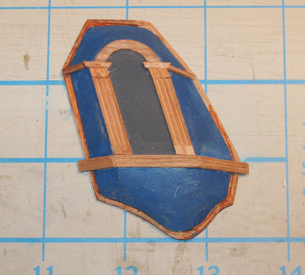
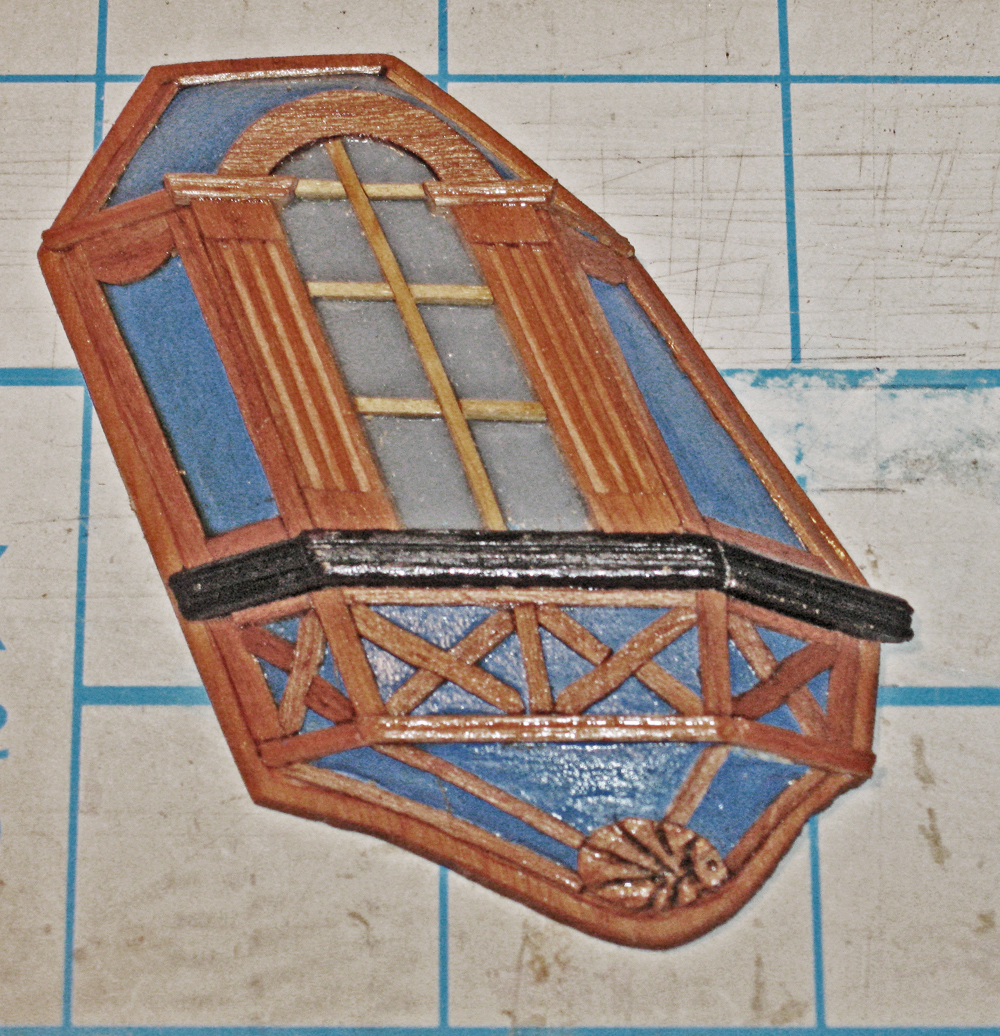
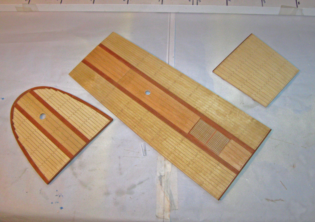
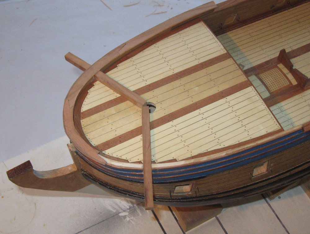
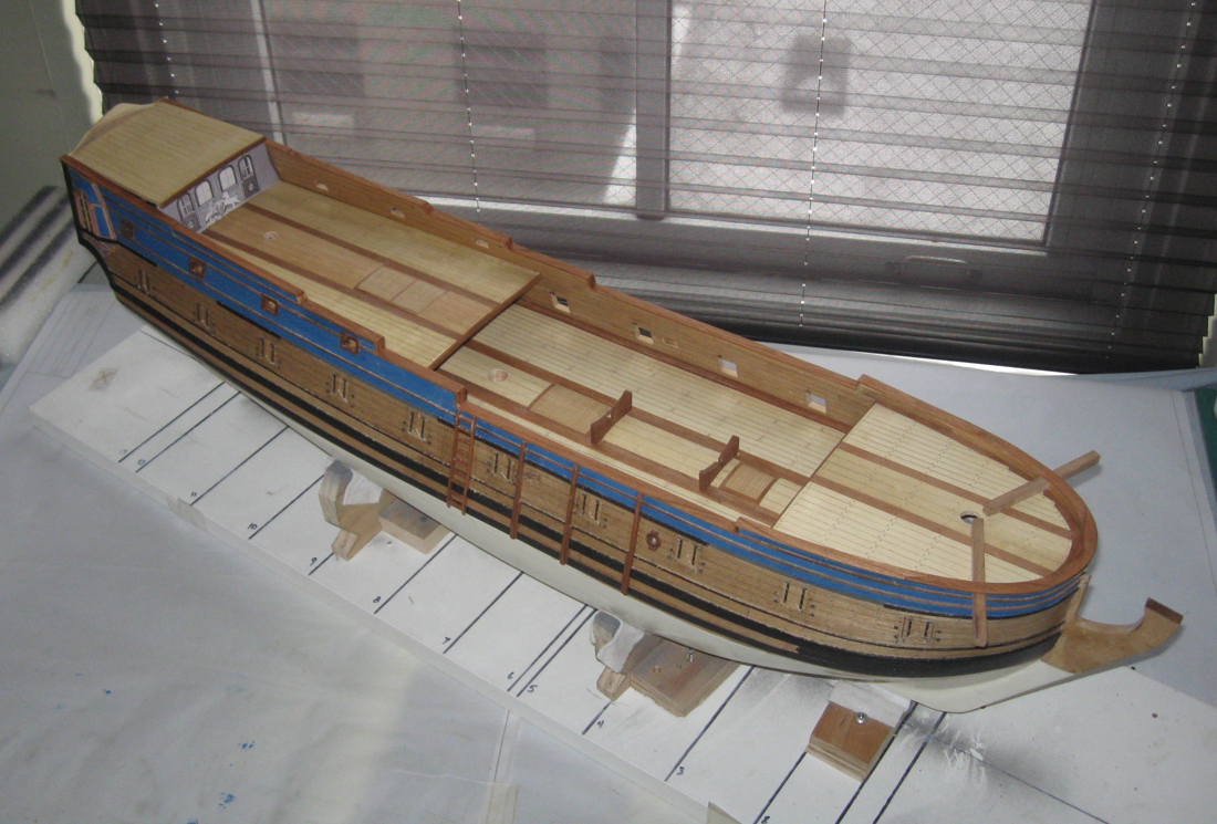
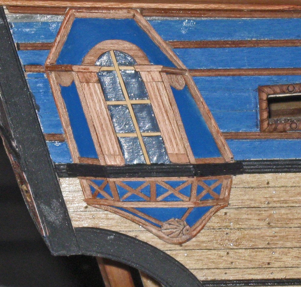
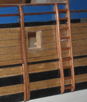
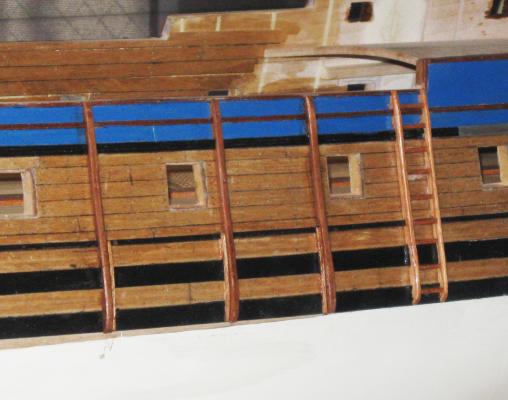
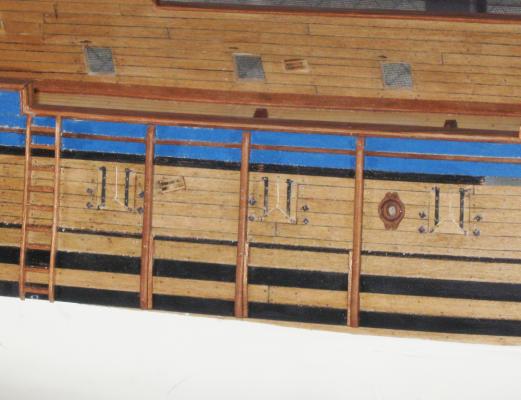
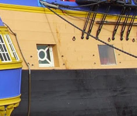
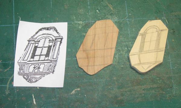
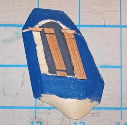
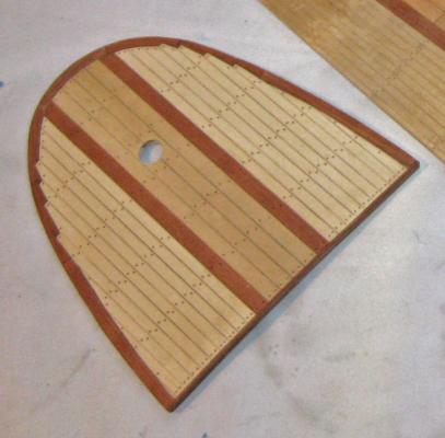
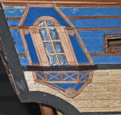
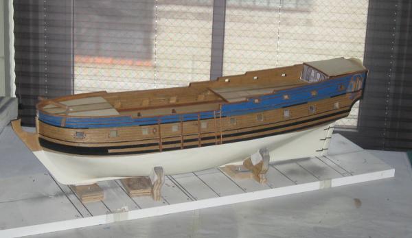
Hi again to all, and thanks for the likes and comments. I replaced the images on page 5 that disappeared, but I ended up with some duplicate images that I could not remove. Just ignore them. I am also having trouble with line spacing, so this is stretched out more than it should be. If anyone knows how to fix this, please let me know. When the last segment ended, a month ago, the ship had the basic hull structure done and planked as was the visible portion of the gun deck. The initial cambered deck structures were in place, ready for planking. There has been a good deal of work done since then, so this segment is fairly long. With the quarterdeck structure in place I could do the upper gunports with their square wreaths. They were located from the inside of the bulwarks such that the 4-pounder cannon would run out through their centers. A series of small holes were drilled around the perimeter of the port to allow the square lining tube to slide through, as I had done for the larger lower ports. Fit was done carefully, but did not need to be precise, since the outer edges would be covered by the port wreath and the inner edges would be covered by the bulwark planking that would be added later. The wreaths have simple decorations done with small carving bitts in the Dremel. The circular carving was done with a sharpened brass tube. An image of the first one was sent off to the museum for review. Once it was approved, the rest were shaped and installed. Next came the gangway ladders and hull loading skids on both sides of the hull. These require 10 vertical pieces, all fitted to the curve of the hull and notched around the several horizontal moldings and wales. It started with a paper pattern cut from an index card. Where I cut it too large at the bottom a small piece of sticky note pad was laid on to cover the gap. Then a wooden pattern was cut from the paper one and fitted to the hull. Once I was happy with it the top surface was blackened to remind me not to use it on the model (I will need it for model #2). I cut and stacked 5 layers of cherry with the pattern on top. These were all given a coat of clear finish and then “spot welded” to each other with CA glue, one of the few times when CA was used. The inner faces with the notches were cut on the band saw, then the outer faces were shaped with a tabletop belt sander to match the profile of the pattern. In the photo you can see the small piece of wood with perpendicular faces that was used to keep the stack aligned and vertical during the shaping process. Once they were shaped they were popped apart with a blade between the layers. The clear finish does not let the CA enter the grain, so there is no wood splintering or loss. This is a technique I use frequently when multiple parts are called for. The first side of the ladder was installed on the hull and secured with metal pins. Treads ½” long (18” in scale) were glued to the hull with PVA glue and the second side of the ladder was fitted to them and to the hull. Once the three skids were installed they were reinforced with shorter pieces at their lower ends, similarly notched and fitted. This is the port side, with the gunports open for the eventual installation of the broadside. And here is the starboard side with closed gunports where the cannon will be shown housed on deck. In the photo you can also see the sheaves for the sheets of the fore course and spritsail, as well as the chesstree for the tack of the main course. The chesstree was made of cherry, carved with various drill bitts and carving tools, then secured with glue and metal pins. This may be overkill, but for museum work I try to insure that pieces will not fall off any time soon. You can also see the details of the gunport and its lid. As with the gunport lid on the stern ports in the counter, the hinges are made from 1/16” brass strip with the hinge barrels coiled with wire bending pliers. Three holes for bolts were drilled in each and they were chemically blackened before installation. I have not tried the copper/liver of sulphur technique that Ed Tosti and others use, but it looks like something I want to try. No matter how well I clean the brass before immersion, the finish always comes out uneven. Eyebolts were made up and installed in the lower corners and the lifting ropes were tied. The central one leads through a hole in the hull and ties off to a cleat above the gunport. The iron fittings for the recoil rope and train tackle protrude from the hull and have diamond shaped washers. They are mounted quite low on French ships, as you can see in this photo of L’Hermione, the reproduction ship that is the subject of a series of current articles by Roger Marsh in S-i-S. Although that ship is larger and almost 70 years later than QAR, these fittings seem to be consistent. On the inner side of the bulwarks the gun tackle fittings are also a bit different. Rather than an upper eyebolt for the train tackle there is a hook in the bulwark. This matches the fittings recovered during the excavation of La Belle by the folks at Texas A&M. Here is how it is represented on L’Hermione. And here are the fittings on the model. I did not mount the breach rope rings loose since they will all either be hidden or in use. Next I turned to the quarter badges. These are a combination of the simple one from the Advice Prize and the florid one from Budriot’s Le Mercure. Because the interiors will not be seen, I did not have to piece them together, as Chuck is doing with his Winchelsea, but could make them solid. Here is the final layout which is sized to the moldings on the hull, along with the base plate of 1/16” thick cherry and the structure piece made from 3/8” basswood. The basswood was cut to be 1/8” smaller than the base plate all around, then the side panels were angled down from the central flat section to the edges. An initial color coat of blue for the panels was painted on, with a dark grey for the backing of the light. The window is framed by fluted columns topped by molding capitals. Here you can see the several pieces that made them up. The flutes were cut as channels in a long strip on the table saw, then parted off with the miter guage set to the proper angle. Once the columns were set, the upper rounded framing piece was shaped and the moldings were cut and applied. Then the basswood piece was mounted on the cherry base plate. Additional pieces of cherry veneer were cut and installed around the perimeter of the piece, as were the window mullions. The decorative elements were shaped to fit the spaces below the black molding. A modified scallop shell was carved at the bottom of the drop. Window glass was simulated by painting the panes with white glue and letting it dry while lying flat. Here are the two mirror image quarter badges. They are not precisely symmetrical since the hull moldings are slightly different on the two sides of the model. Once completed, they were offered up against the hull and the moldings beneath them were chiseled off to let them lay flat against the hull planking. The deck structures were laid in and tested for their final locations. The grating and other fittings on the quarterdeck were laid out, which gave me the final locations of the mast holes and the length of the captain’s cabin and poop deck. The three removable deck pieces were planked in the same manner as the gun deck, although the tops of the binding strakes were not raised above the rest of the planking. A square hole was cut into the quarterdeck for the grating, which was sunk till it matched the level of the binding strakes. The outboard sections were made from sheets of holly veneer with the planks scribed in. This simplified the process of tapering the planks immensely on the quarterdeck and poop deck pieces. Deck beam locations were penciled in and fasteners for each plank were drilled, filled, and sanded flush. For the foredeck the cherry margin plank was installed first, then the central planks and binding strakes. The outboard pieces were cut overlarge to allow me to shape them as if they were nibbed into the margin planks. Once they were cut they were offered to the deck and the outline of the nibbing was drawn on the margin plank. The overlaps were carefully chiseled out of the margin plank till the holly pieces fit tightly into their spaces. Caprails were cut from 1/16” cherry. These were fairly simple straight pieces, although the width tapered from 10mm (15”) at the waist to 7mm (10”) at the extreme aft where the rail meets the transom. With the quarterdeck located and planked, the square holes for the anchor davits could be cut. Above them the curved caprail was shaped from five pieces of cherry, scarfed together, the given a final shaping after installation. In the photo some temporary straight anchor davits are laid in, but will be removed and replaced with bent ones in the final fitting out. So here is the current progress. Not visible are the steps for the fore and mizzen masts that lie under the decks, as well as the mounting block for the bowsprit. These were drilled and carefully aligned so the masts would line up along the centerline with the correct rake for each. Next I will detail the transom and put together the headrail structures. I hope to bring this to you soon. Be well Dan


- 241 replies
-
- 15
-
-

-
- queen annes revenge
- pirate
- (and 2 more)
-
Hi all - This is off topic, If you know where it should be posted, let me know. I recently read a thread which asked for a recommendation for an illustrated glossary of ship terms. Unfortunately, I can't find it now. In any case, one of the best general introductions that I have run across is: "The Visual Dictionary of Ships and Sailing" produced by Eyewitness Visual Dictionaries. It is a slim book but covers topics from the first boats to modern underwater diving gear and ROVs. Obviously, it can's do justice to everything, but does an excellent job for the things that it selects. The best part is that many topics are illustrated with either the actual object or photographs of top quality models. Hope that helps. Dan
- 241 replies
-
- 1
-
-
- queen annes revenge
- pirate
- (and 2 more)
-
Hi all - Thanks for the likes and compliments, and to all those who saw the model up close at New London yesterday and had good things to say. Crackers - yes, the last slave cruise of the QAR was not a nice experience for anyone aboard. It actually ended best for some of the slaves who joined Blackbeard's crew. The other slaves, along with the French captain and crew, were set down on an uninhabited island but were given a small sloop, after it was stripped of armaments. It says something that the crew took the remaining slaves and sold them in the Carribean before returning to France to give testimony about the loss of the ship. Jon - thanks for the compliments and for letting me know that some images have disappeared. The infection seems to be limited to page 5, and I will restore them in the next day or two. Be well Dan
- 241 replies
-
- 1
-
-
- queen annes revenge
- pirate
- (and 2 more)
-
Hi Mark - The adventure begins. . . and we all will be eagerly watching the trip. Dan