shipmodel
-
Posts
941 -
Joined
-
Last visited
Content Type
Profiles
Forums
Gallery
Events
Everything posted by shipmodel
-
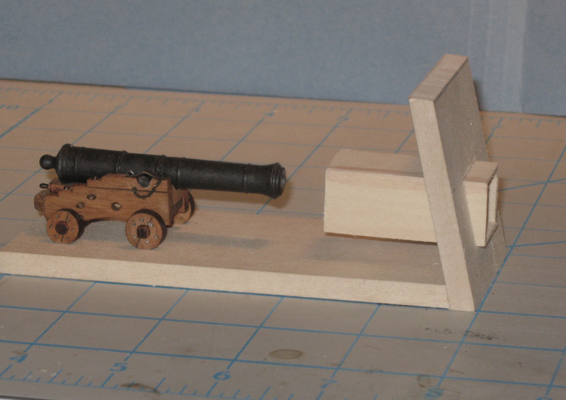
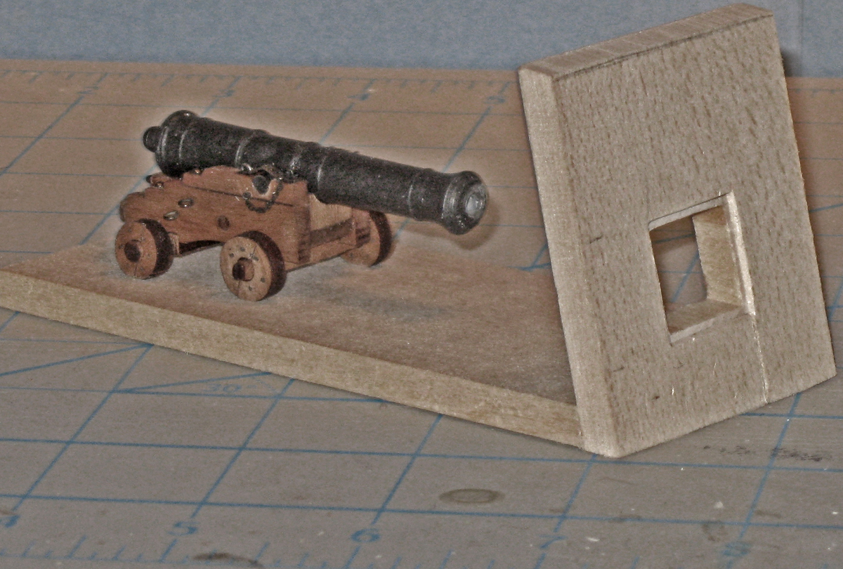
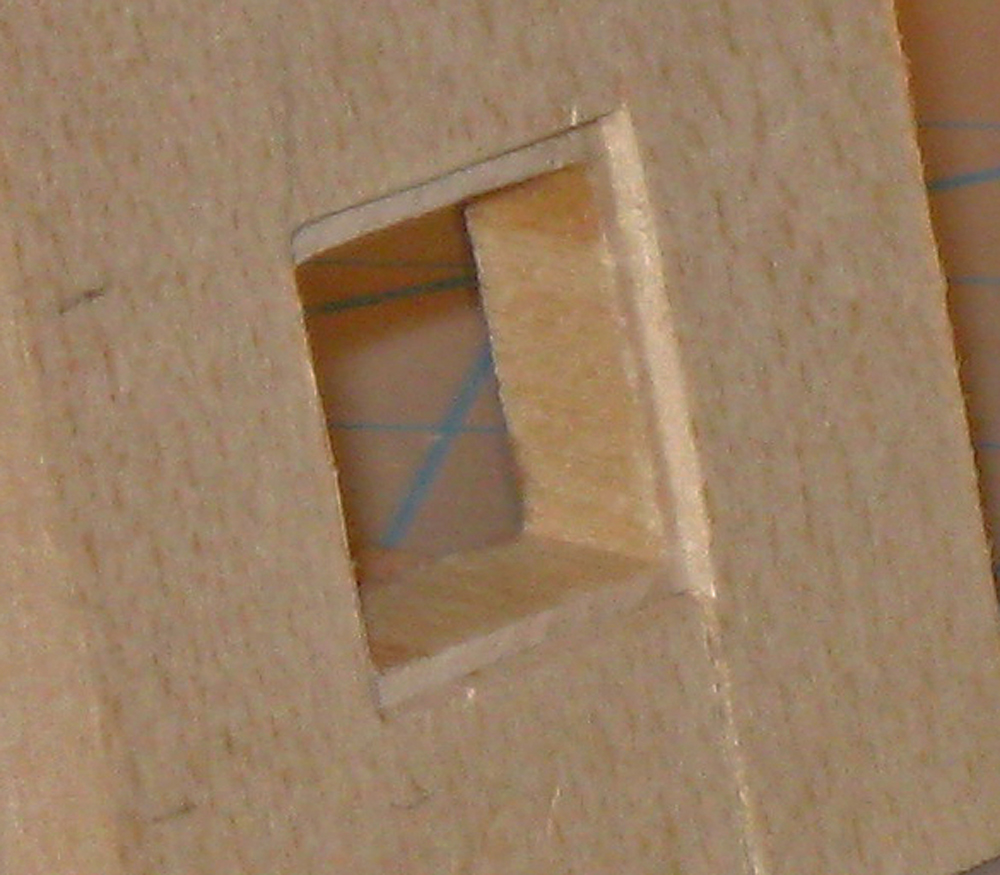
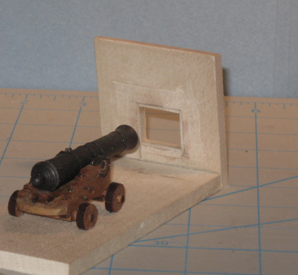
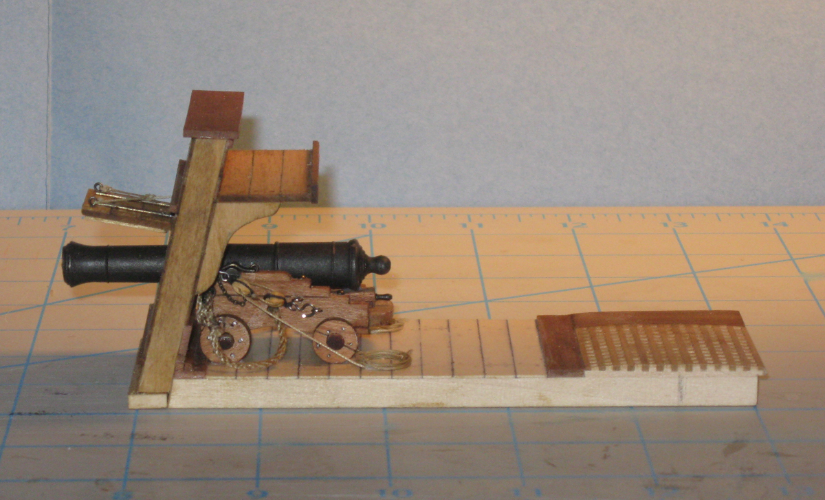
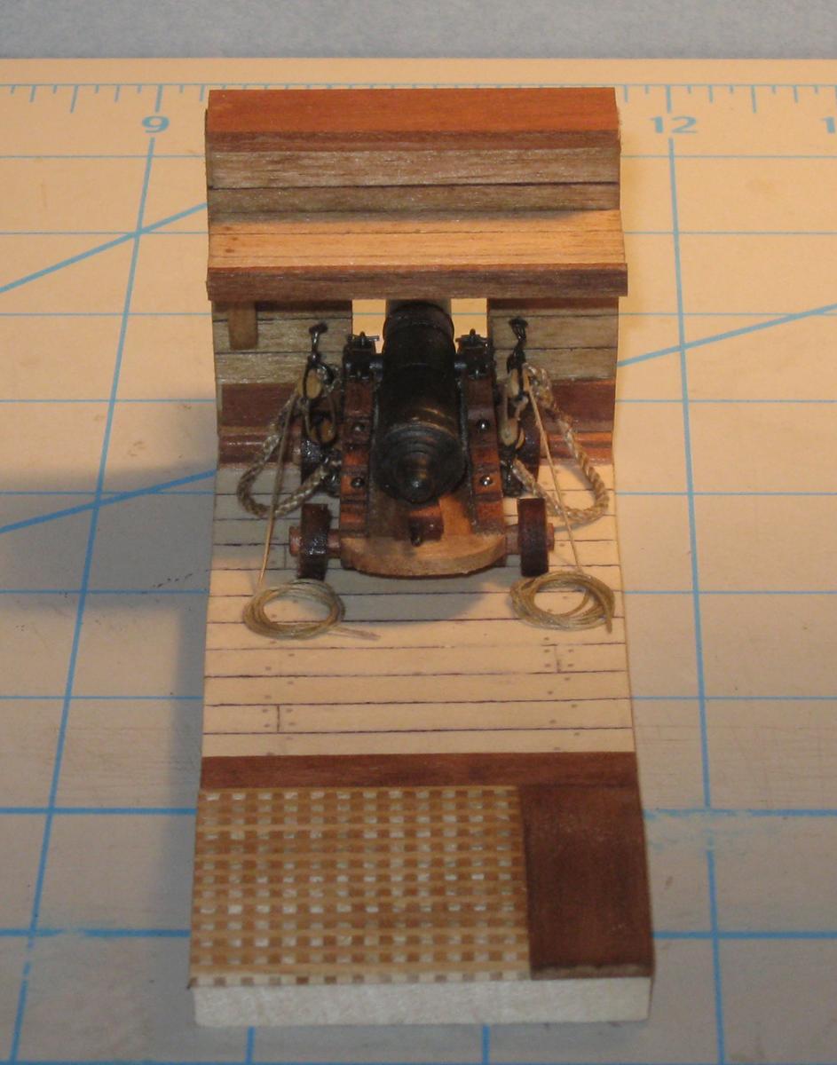
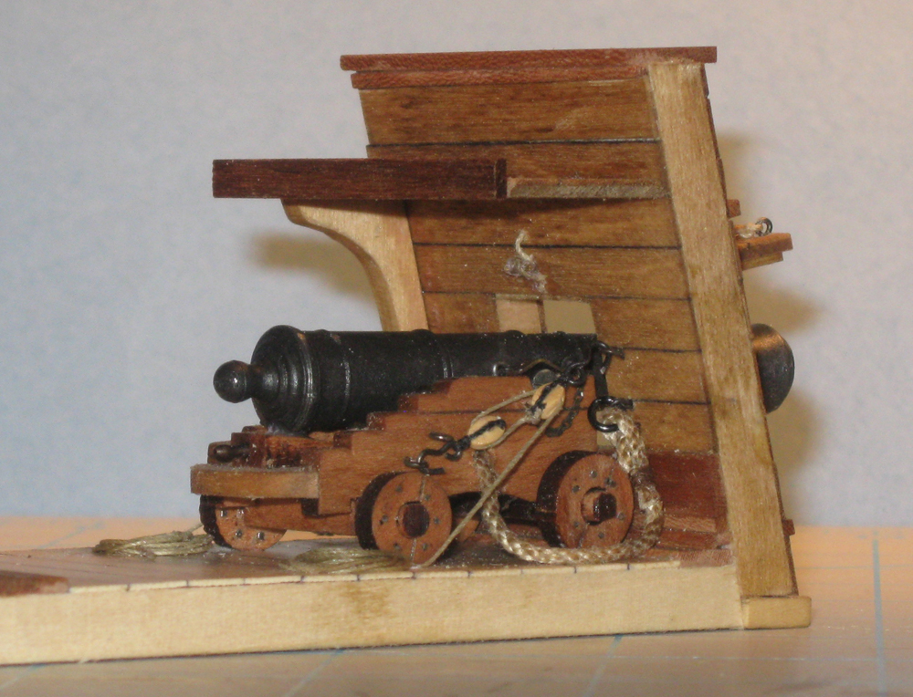
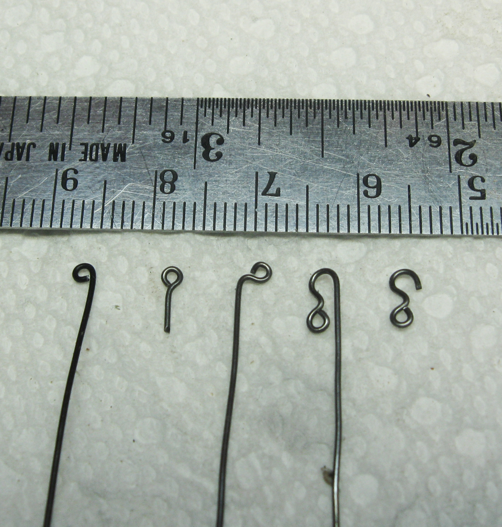
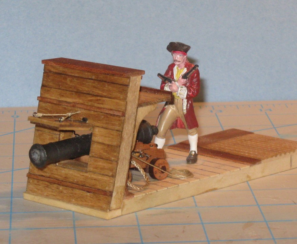
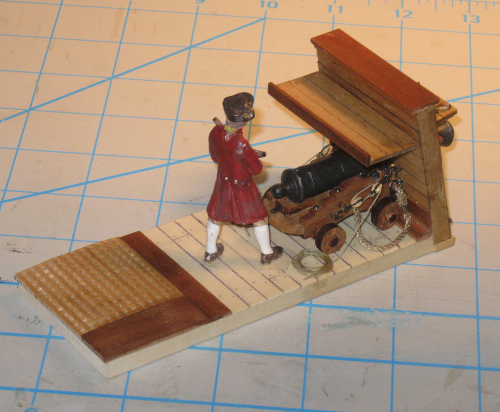
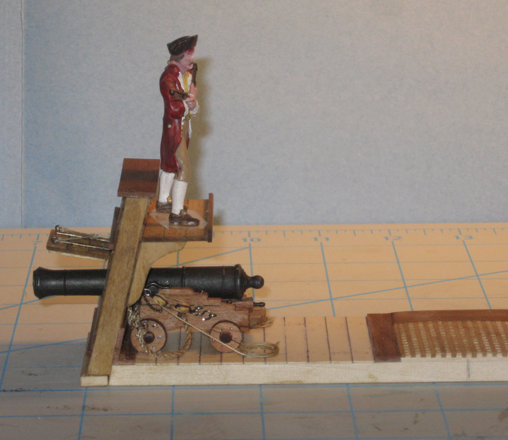
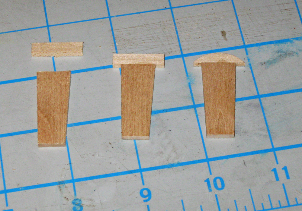
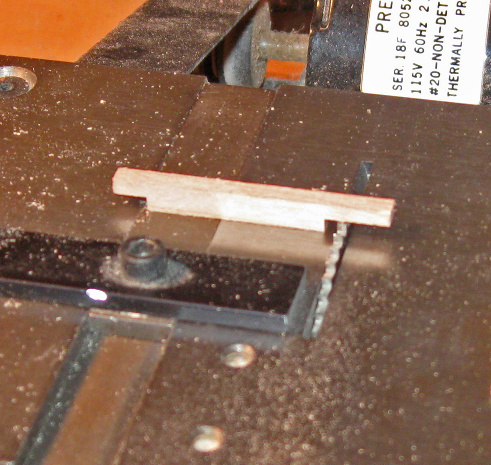
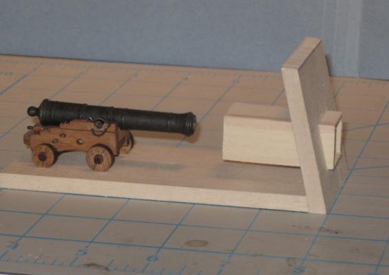
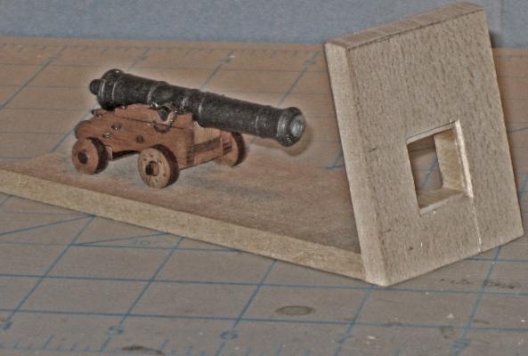
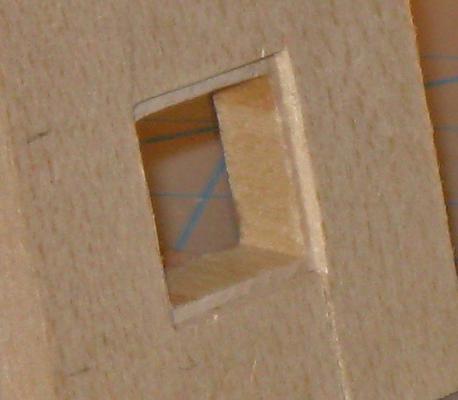
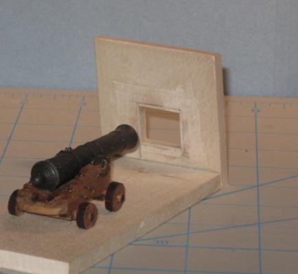
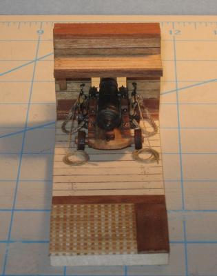
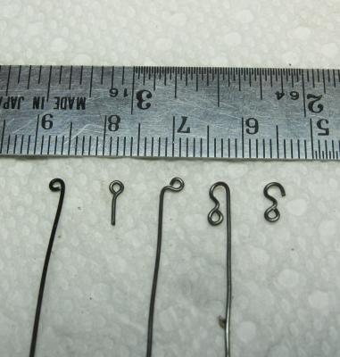
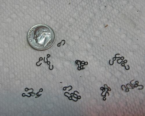
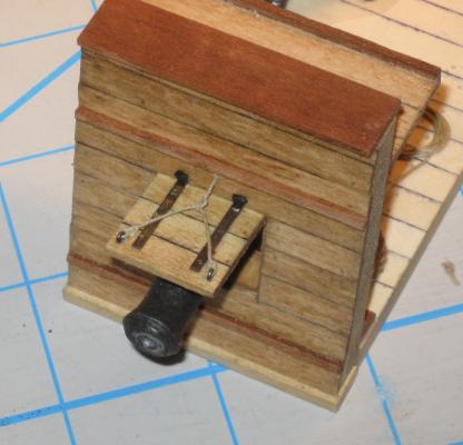
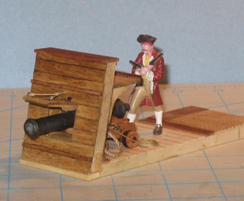
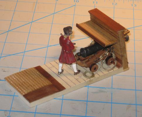
 Hi Michael - Yes, another good idea. I will play with them all the next time around. Moving ahead, I have been thinking about the methods and materials that I will have to use when it comes time to mount and rig the cannon. Once the bulwarks are in place on the hull the tumblehome is going to make rigging the cannon difficult. Then there are the deck and hull plank details that have to be worked out. . . . etc. . . etc. I decided that making a mock-up of a gun station would help me work out some of the kinks. The first issue was how to cut the gunports through the bulwarks and create the rebate for the lid. I wanted them all to be the same size and square. The method that worked for me was to create a square tube of 1/32” wood glued at the corners. Here you can see it slid through a hole cut in the bulwark. With a small piece of bulwark like this, I could cut it on the band saw before attaching it to the base plate. On the model I will have to pierce each gunport and use a coping saw to cut the square hole. Here it is from the side. You can see that it runs parallel to the deck, so the lintel and sill will be level. With it in this position I marked out the line where the box and the outer bulwark face met. The box was removed and cut along the line. The cut face was sanded, and the box reinstalled in the hole, but slid in just short of the outer face of the hole. In the closeup you can see the even and smooth rebate formed this way. The back side was marked, the box removed and cut down, then reinstalled and glued. When the glue was dry the back side was sanded smooth with the inside of the bulwark. The rough edges and gaps will be covered by the bulwark planking. All the gunports should be identical if I slice similar sections from the same tube. Construction went very quickly. Too quickly. I forgot to stop and take photos. Here is the completed gun station. It represents one of the midships cannon in the waist with the high bulwark and the gangway overhanging the gun. If you look at the bulwark, you will see that it has been raised about 1/8" from the first few photos. It reminds me not to take measurements from the plans without checking them against the rest of the details that have to fit. This would have been a disaster if it happened on the actual bulwark piece. The deck layout is taken from the plans, with the raised binding strake used by the French set just outside of the grating. While doing this I discovered that the gratings that I made earlier will have to be modified. The French did not use the high coamings which the English did, and which I built. The QAR would have had gratings set into the deck, but crowned even more than the deck camber/round up. I took an extra piece of grating and sanded it down at the sides and across the back until it fit the curved profile. The deck is laid in holly, with birch bung covers. I know that there are good arguments to be made for making them pronounced, and just as many for making them invisible. I chose to take a middle course and try to make them visible, but not distracting. Here is the cannon rigged with its breeching rope turned into rings in the bulwark. The rope was laid up from DMC cotton line to a diameter of 0.6” (scale 6 inch rope). It was stained and sealed with Minwax. There is still some fuzz, but I am working on a few solutions. The gun tackle are hooked to eyebolts. The blocks are 4mm singles from Warner Woods West (6” in scale). The hooks are tied into their strops and the block closest to the bulwark has the running line tied into its becket. The line is J.B. Coates “Dual Duty Plus” that measures out to 0.015” This is a little thin, but I prefer the look to that of a thicker line. I could not find acceptable photoetched hooks on the market, so I made them from 0.020” iron wire. The sequence below shows how I use my orthodontic pliers to bend the wire around to meet itself, then the eye that was formed is bent back to center on the shaft. To make an eyebolt it is clipped off at this stage. To make a hook I continue the bend to stage 3. Moving the pliers out just a bit the wire is bent back toward the eye, then clipped off, opening the hook. The smallest hook I can make this way is just under 5 mm (7” in scale). This is a bit large, but acceptably small, and the 50 that I needed were done pretty quickly. The outer bulwark planking was cut from birch veneer with the edges colored with indelible marker. I experimented with contact cement as the adhesive. I painted a thinned layer on the bulwark substrate and let it dry. The planks were painted but installed when the glue was still a bit tacky. This gave me quick adhesion but just a little ‘wiggle room’ before it set. The bad news was that the contact cement dissolved the indelible ink and threatened to spread it to the surface of the planking. I will change to a water based marker in the future. Treenails were drilled and installed, then the planking was stained. I used Golden Oak, but did not thin it enough and I think the color is too dark. Neither the treenails nor the moldings show up to good effect. The gunport lid was made up as usual from several layers of wood glued with crossed grain. The hinges are blackened brass strip pegged with iron wire. The strips were left long beyond the back edge of the lid and were ground down to square cross section. These pins were inserted and glued into holes drilled into the plank just above the lintel of the gunport. Hinge barrels were made from short sections of blackened brass rod. Small eyebolts were made and fitted to the outer corners and a bridled lifting rope tied. The lead is through a hole in the bulwark above the gunport and belays to a cleat above the gun. Of course, Pirate Pete had to show up to inspect the work. He seems to fit well into the scene. He even looks the right size for the gangway, although he can use a rope railing on the caprail. Overall, I would say that the two days spent on the gun station were well worth it for the time that will be saved over the long run, and the problems that will be avoided. Be well Dan
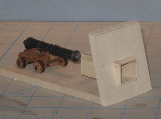


- 241 replies
-
- 18
-

-

-
- queen annes revenge
- pirate
- (and 2 more)
-
Hi Mark - Out of the starting blocks and into the first mile of the marathon. Glad you were able to salvage as much of v.1 as you did. Nice idea to put the batten down on your reference line. Following with interest. Dan
-
Thanks for the likes - Druxey - just another case of caveat emptor. Is there anything the silly stuff does work on? Now I have to get rid of it in a responsible manner and I don't even know what it is made of. . Mark - yes, annealing the brass might help. I will try it with the set for the second model. I also thought that hardening the edges of the groove in the base plate might give me a crisper bend. Dan
-
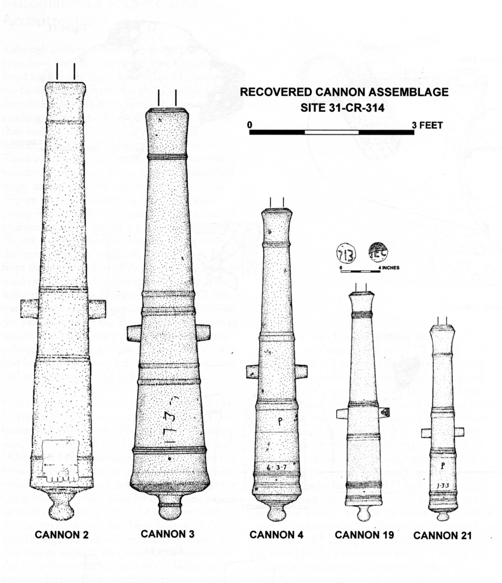
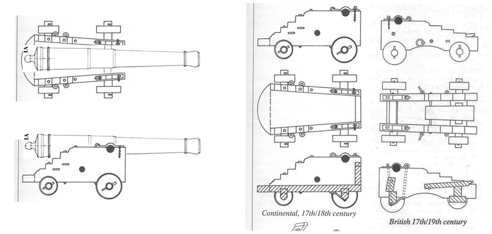
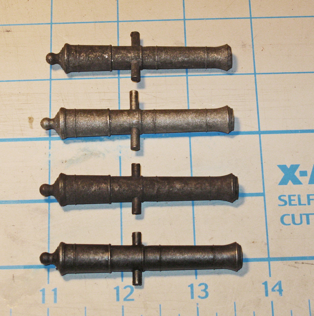
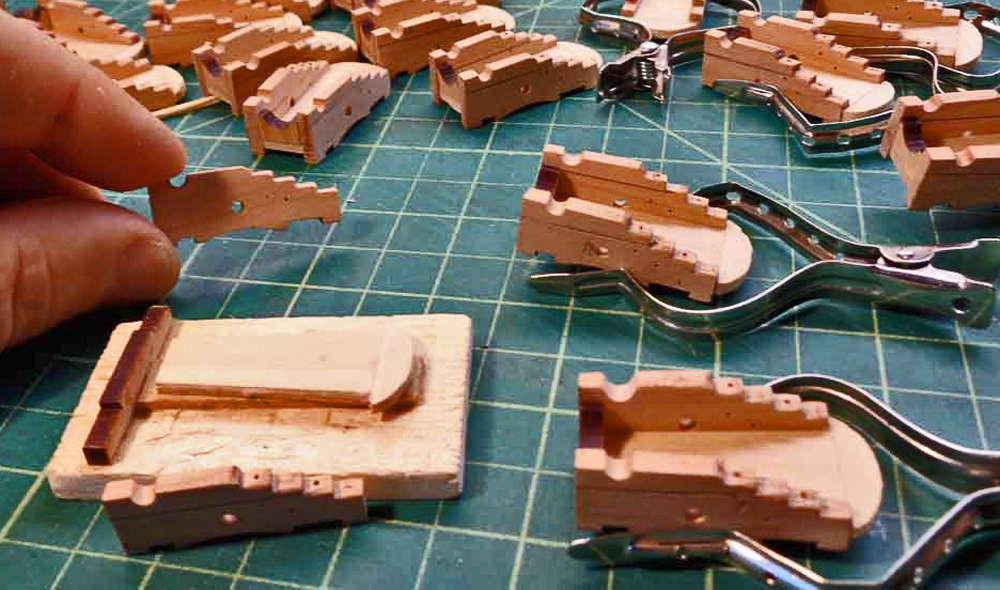
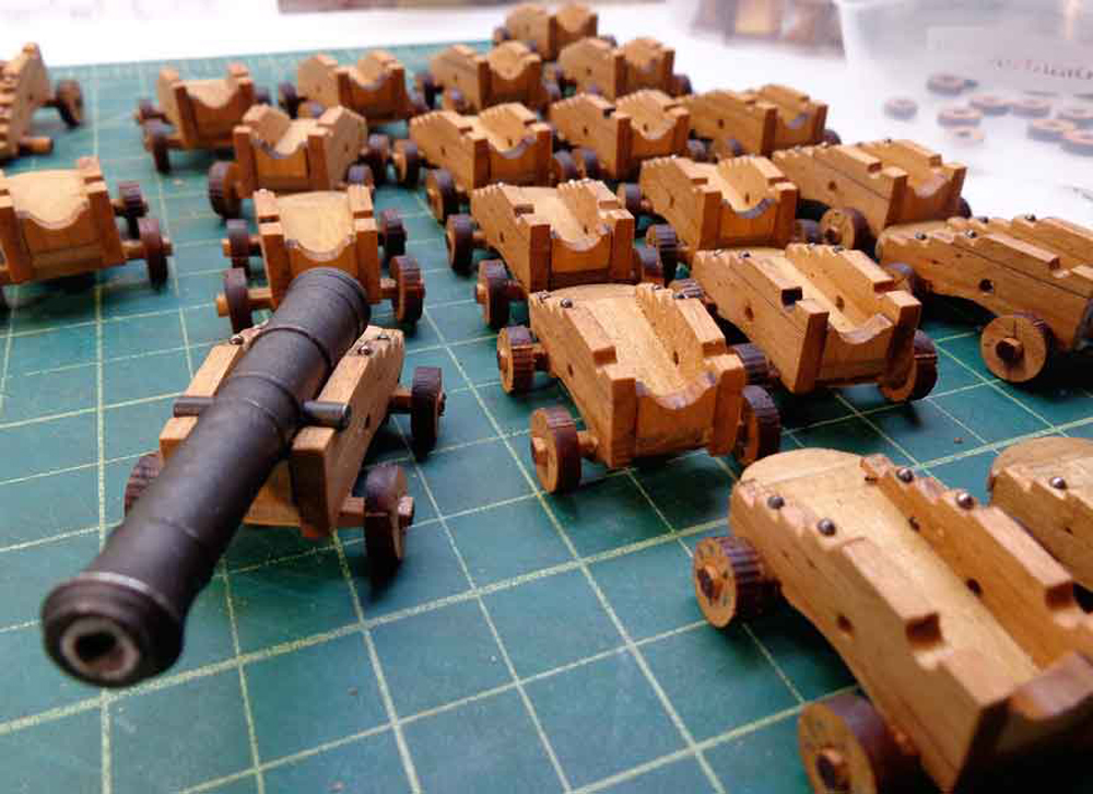
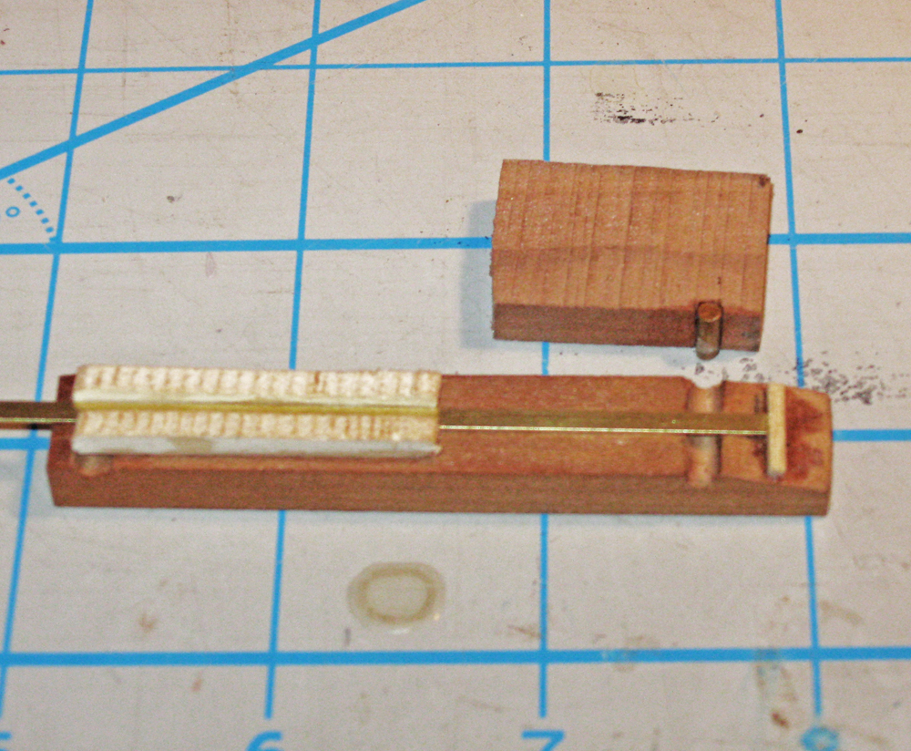
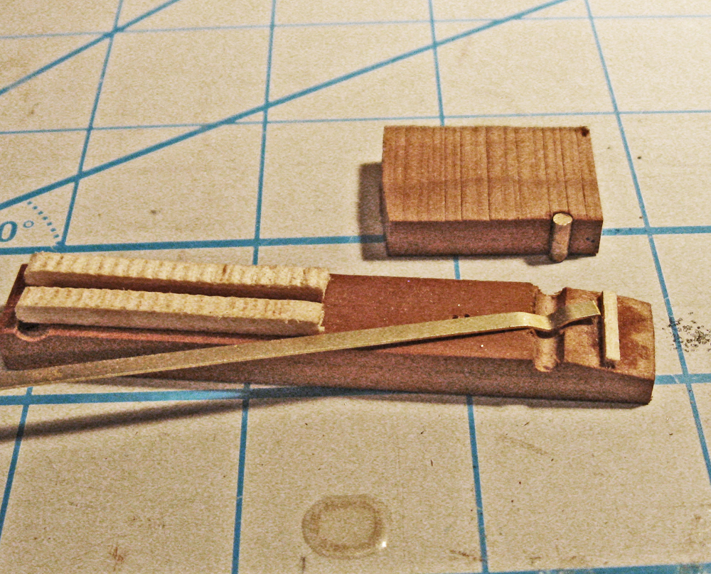
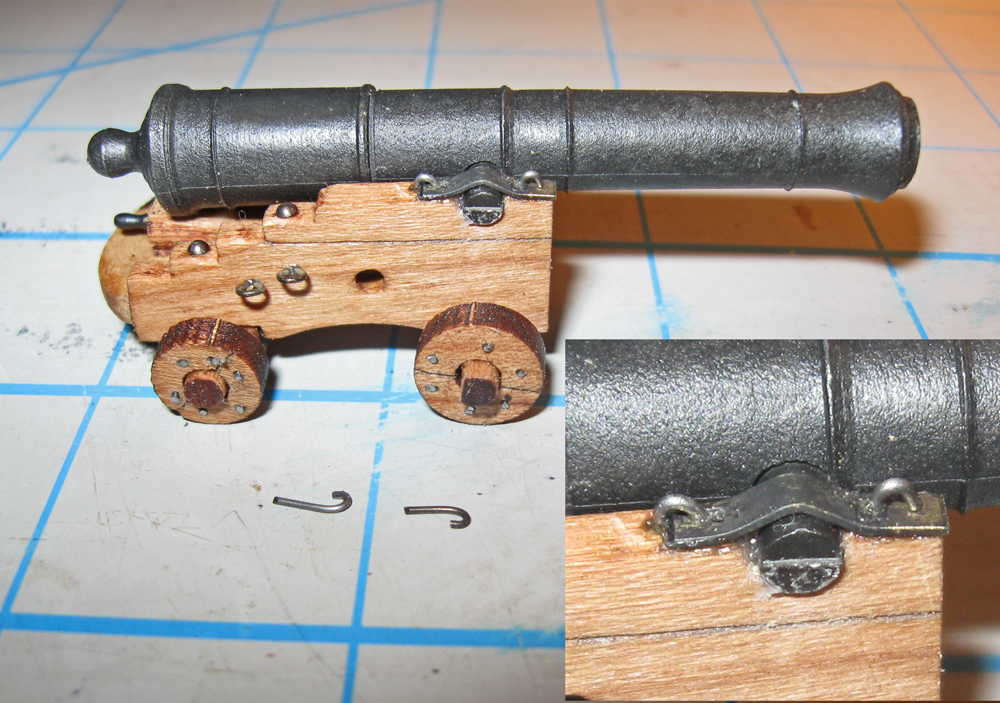
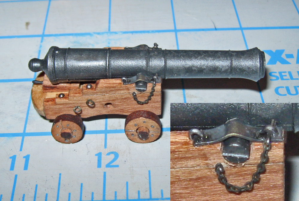
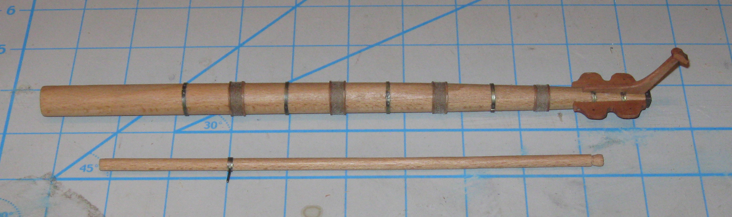
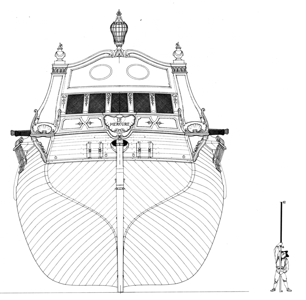
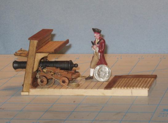
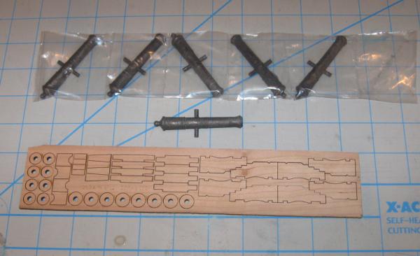
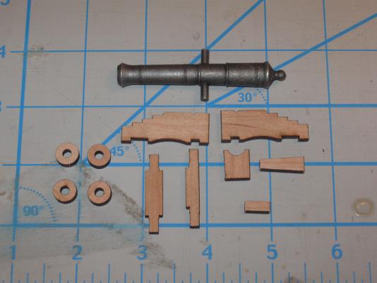
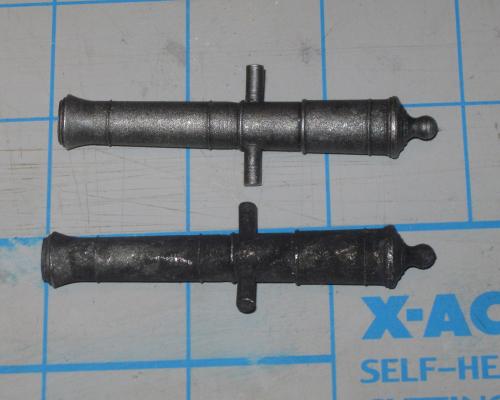
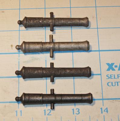
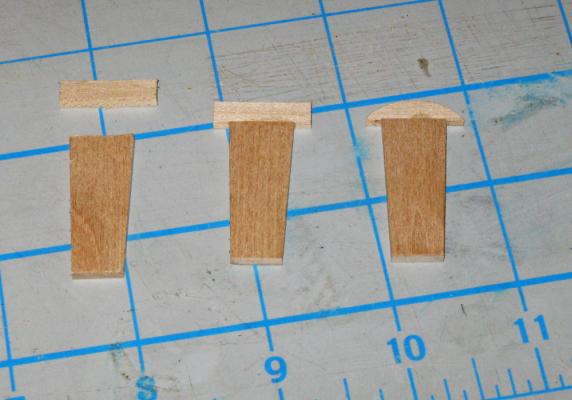
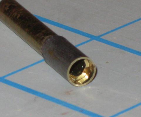
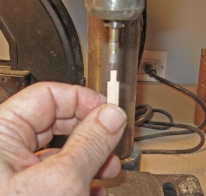
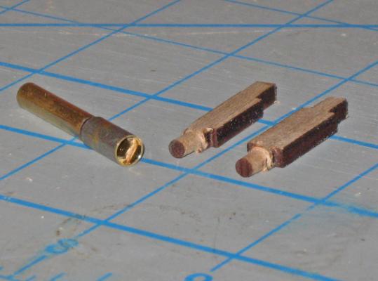
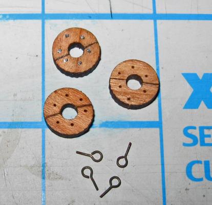
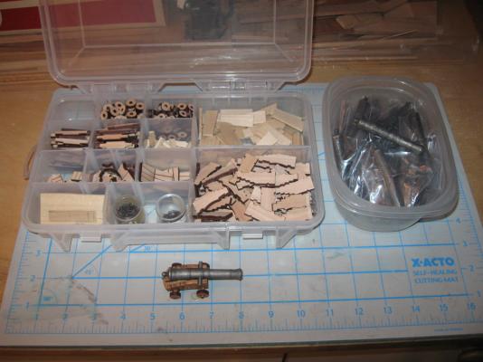
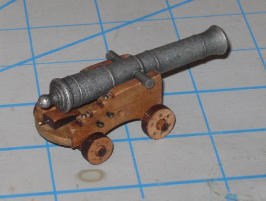
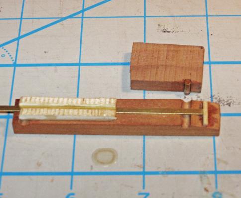
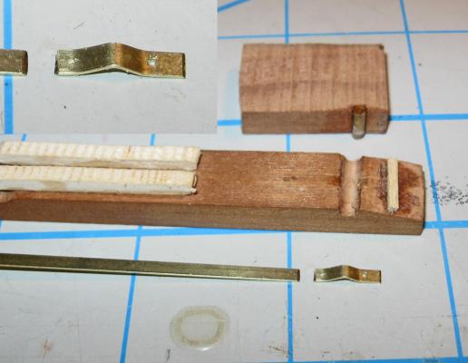
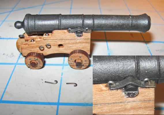
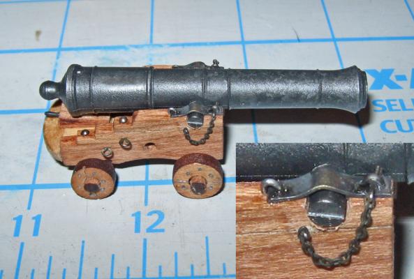
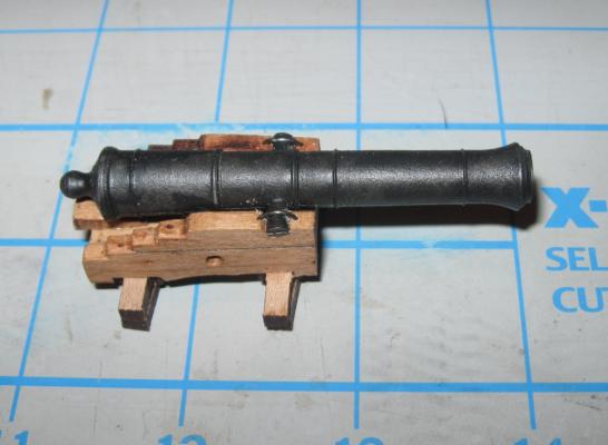
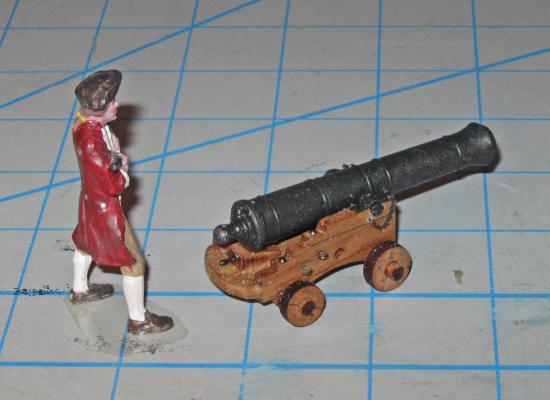
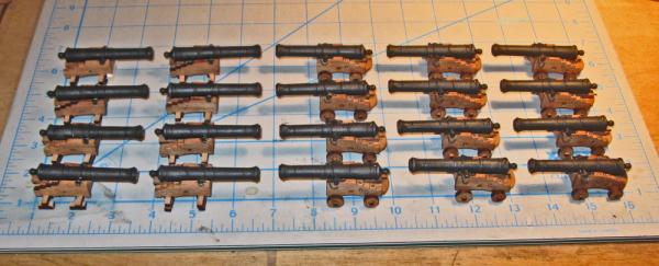
Hi all - David, thanks for the link. It was an interesting article and fills in some gaps in my knowledge of the history of the ship and Blackbeard. Now it is time to turn to the armaments. On any pirate ship model the cannon are going to be significant points of visual interest and the QAR is no different. After Blackbeard’s capture of Le Concord, he took the armaments from his prior ship and added them to those already on his new flagship. Contemporary accounts put the number of large cannon at 20, with an unknown number of additional smaller ones. Archaeological evidence from the wreck site confirms this. Several six-pounder long guns have been recovered and conserved, as well as a few four-pounders, a one pounder and a swivel gun. It was therefore decided to arm the QAR with 20 six-pounders on the gun deck, with four four-pounders on the quarterdeck and two one-pounders on the forecastle. Ten swivel guns will be mounted on the rails along the quarterdeck and forecastle. The cannon that have been examined turned out to be a mix of English, Swedish, and French manufacture, which is not surprising. Blackbeard, like all pirates, would have obtained his armaments from whichever ships he had previously captured, which might themselves have had a mixture of cannon. No carriages were recovered, but the decision was made to mount them on French style carriages since she was originally a French ship and possibly retained most of her larger cannon. Here are drawings comparing the French and English styles. As you can see, the basic differences are that 1) the French style has a solid base plate and bumper, which widens the footprint of the carriage a bit; and 2) the breaching rope runs through large holes in the cheeks rather than looping around the cascabel. The rounded curve on the bottom of the English cheeks is not unique, and I have seen carriages with them on contemporary French models. With so many cannon to build, I looked to the aftermarket to see if anyone had barrels that would scale out to the 6 ½ to 7 ½ foot length of the six-pounders that were recovered and still be historically accurate in shape and detail. The length scaled out to between 2.16 and 2.5 inches. I found that The Lumberyard (www.dlumberyard.com) had cast Brittania barrels that were just the right size. They are listed as 32-pounders if you are working at 1:48, but the shape is correct for the smaller caliber at my larger scale. I carefully examined enlarged photos of the barrels and was impressed with the detail and accuracy of the reinforcing bands, cascabel shape, and bore. I ordered 40 of them, as well as 12 others for the smaller cannon. They did not have acceptable barrels for the swivel guns, and I am still looking for them. The Lumberyard also sells laser cut carriages to fit the barrels. They were made in the English style, but I thought that I would try to modify them to the French style. I knew that I could always scratch-build the carriages, but the pre-cut ones would save a lot of effort if they could be made accurate enough and of the right style. Here is how it went: This is how the barrels and the carriages came. The carriages come four to a sheet, which worked out perfectly. The barrels and carriages for the smaller guns are identical in everything but size. A lot of thought and care went into designing the carriage pieces, including providing two different sizes of wheels/trucks. A tip of the hat to Dave Stevens. And here are the pieces for one cannon after being separated from the laser cut sheet. They came out easily and a little help with a sharp blade was only needed once or twice for all the pieces. The barrels are excellent castings with no flash and almost no evidence of the mold line. But whatever blackening method was used did not ‘take’ on the metal. It was uneven, crusty, and could be rubbed off with a finger. A bit of work with a dry paper towel took the blackening off down to almost bare metal. To re-blacken them, the contract specifications call for chemical blackening of all metals rather than paint. I first tried a product called Blacken-It, which was a disaster. The metal took on a grey, chalky surface, while an unidentified tan substance precipitated out of the solution. I had much more success with Pewter Black. I experimented and found that I had to use a fairly strong solution, much stronger than the corresponding solution of Brass Black that I use for brass. The surface that was produced was more uniform, but some of the blackening could still be rubbed off if I put some effort into it. To seal it several coats of clear matte finish were sprayed on and the end results were acceptable. Here you can see the barrel at the top as it was received. The next one down has all of the blackening removed with a powered toothbrush. Below it is the barrel after the trunnions have been cut down and reblackened. Finally, the finished barrel after clear coating. Only the vent hole has to be drilled. The carriage conversion started with making the base plates and bumpers. The tapered base plate was cut on the table saw with the miter gauge set to 5 degrees. The bumper was cut, attached with PVA glue, then crowned using a disc sander. The cheek pieces were sanded smooth and the burn marks from the laser were sanded off. Holes were drilled for the eyebolts and the breaching rope through the side of the cheek, and holes for the bolts holding the cheek pieces together were drilled down on two of the steps of the cheek. A simple jig was fashioned that held the base plate up so the axle notches would be clear, and located the cheeks against the bumper. The vertical cross piece at the front held everything square. A clamp made from a bent hair clip held it all together as the glue dried. Axles and wheels were next. As they came out of the wood sheet, the axles were square. They needed to be rounded to fit the holes in the trucks. To do this I found a piece of thick walled brass tube with the correct inside diameter. Four teeth were cut and filed into one end and a sleeve was put around it as a guide and depth stop. This was chucked into the bench top drill press and the ends of the axles were fed into it from underneath. There was surprisingly little resistance as it cut, and I was able to control the workpiece with just my hand. It made short work of the job, and much neater than I could have done by hand. The trucks from the laser cut sheet were modified to make them look as if they were made up of four half circles bolted together with six metal bolts. The effect is subtle, but noticeable if not done. Next to them are several of the eyebolts located in a store here in NYC. The eye is 0.095” o.d., which scales up to 3 ½”, which is quite accurate. I could have wished that the wire was a bit thicker, but the difference is hard to see. At $2 per hundred it sure beats making them all by hand. A test cannon was done to see that everything worked, and a detailed instruction sheet was written up, then all the carriage pieces were packed up and given into the hands of JerseyCityFrankie, who agreed to assemble all the carriages. He did an excellent job, as you can see from some of his progress photos. Frankie also shaped and installed the quoin wedges. The handles are brass belaying pins treated with Brass Brown solution. All that was left to do when I got the completed carriages back was to make and install the capsquares and their fittings. I started with a strip of 3/32” x 1/64” brass and developed a jig to shape it. The strip is held between the guide strips and pushed up to meet the stop on the right. The die has a short piece of steel rod set into it which matches the groove cut into the base piece and is the same diameter as the trunnions. The steel rod is placed over the groove. With a few taps of a hammer the curve is bent into the brass. The first few tries showed me that if the base piece remains flat the short end of the strip does not bend flat but springs back a bit. To correct this the end of the plate was angled and some finishing strikes with the die held at an angle took care of the problem. Two holes for the eyebolts were pre-drilled in the capsquare while it was still on the strip, then it was parted off. You can see in the inset that the curve is not as rounded as I might have liked, but the difference is not noticeable in the finished piece. The capsquares were chemically blackened and tack glued in position. The pre-drilled holes were extended down into the wood of the cheeks. Two U-bolts with one very short leg were bent and installed. In the inset you can see that the one toward the rear of the carriage replicates the visible portion of the eyebolt that hinges the capsquare, while the other replicates the eyebolt for the pin that holds it down. The final detail was the pin and chain for each capsquare. Some very fine brass chain with 36 links per inch was blackened, and bits of thin wire inserted in links about half an inch apart. The wire was bent back on itself and pinched together to form a cotter-pin shape. One pin was left long and inserted into a hole just below and behind the trunnion, while the other was cut short and slipped into the eye of the forward bolt. The gun is now ready to be mounted and rigged. And here it is with my scale figure for comparison. I think it came out quite well and will dress up the waist of the model nicely. Actually, there were two types of carriage that were made. On the finished model only the eight guns in the waist will be visible. These are the only ones that needed to be fully detailed. However, just to be safe I detailed the four cannon that might be partially visible under the overhanging quarterdeck and forecastle. The remaining eight will only have the end of the barrel and the forward face of the carriage visible. For these no bumper was installed and the capsquares were replaced with simple U bolts. The trucks were replaced with wooden chocks that raise the cannon to the correct level and will provide enlarged glue surfaces when the cannon are installed. So here is a complete set of all the six-pounder cannon for one of the models. The remaining small cannon will join them shortly. This was a longer entry than usual, so feel free to ask if I have not fully explained any of the materials or methods. Be well Dan


- 241 replies
-
- 13
-
-
-
- queen annes revenge
- pirate
- (and 2 more)
-
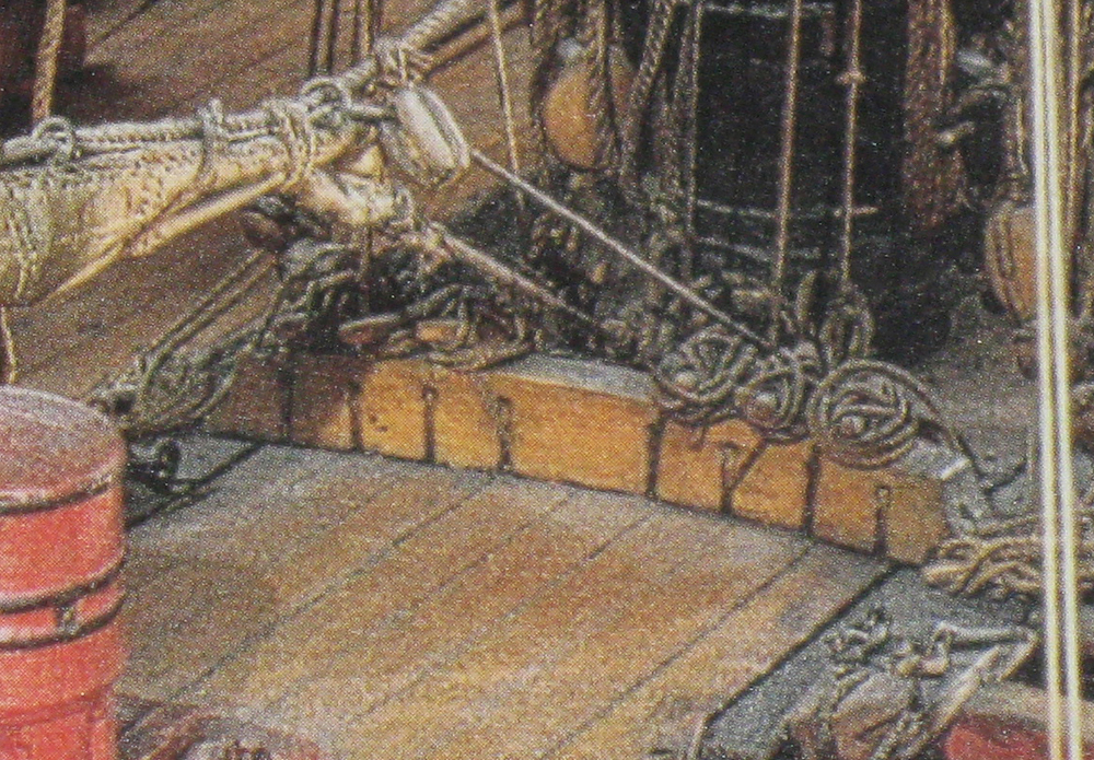
Hi all - Thanks for the responses. They mirror my own thoughts. Paul Fontenoy at the North Carolina Maritime Museum found a reference to them in a 1734 French treatise on rigging and sail handling, and another Budriot reference where he calls them “taquets retours manoeuvres” which translates as “return cleats” Studying them on the model it does not look as if they could have sheaves, but just tunnels under the fitting though which the lines run. I can't see how you would install the sheaves and their axles in such a long piece of wood. This is known as a "dead block" in some rigging books. The French do this frequently, as witnessed by the yard ties which go over the caps and run in greased grooves rather than using blocks. JerseyCityFrankie pointed out that the design does not work well, and he is right. The stress on the cleats is from the wrong direction, and the lines have to go over a sharp corner which could abrade them quickly. But the lines that come down and are belayed here look light, and are probably the bunt and leach lines for the lower courses and the topsails. The downhaul and brails for the staysails look to belay here too. These are not lines that would work back and forth a lot or be under a lot of strain. But it is probably one of the reasons why this fitting was quickly replaced by a pinrail. Anyway, it makes an interesting difference from well known English practice, and I think I will use it unless Paul has some definitive evidence that it would not be appropriate for the QAR. Dan
-
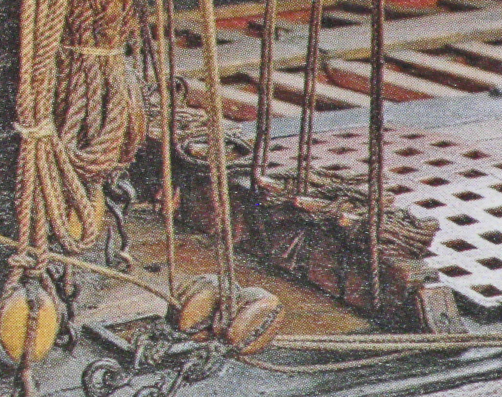
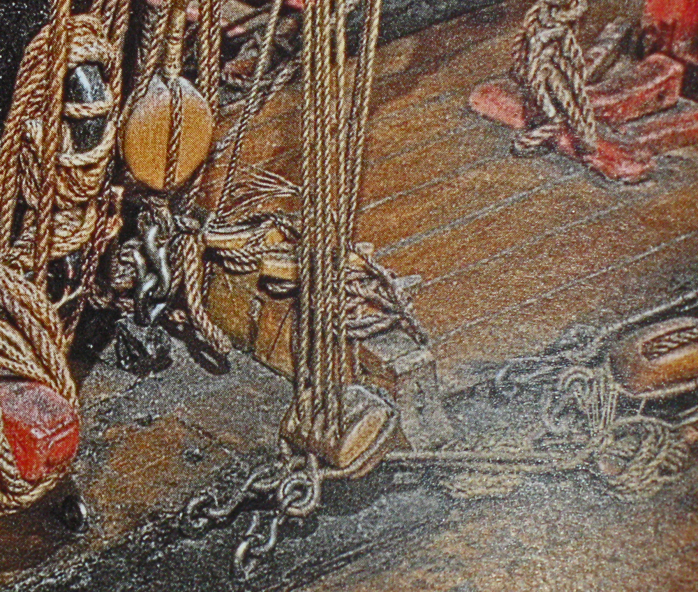
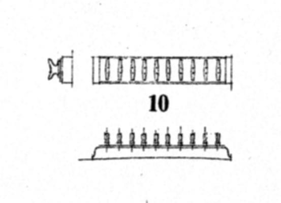
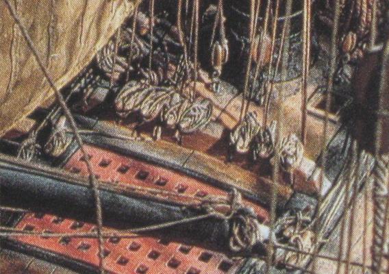
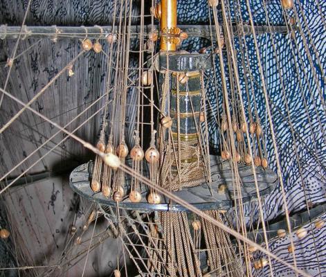
Hi all - I am stumped on a fitting fixture that appears on the Budriot plans. It is a wooden piece, about 6" x 10" in scale and about 4 feet long that sits on deck athwartships to the stern of the fore and main masts. It has a series of sheaves along its length and is topped by a matching number of cleats. It clearly takes the place of a pinrail to belay lines coming down from the top. Here is Budriot's plan, although he does not show the sheaves. He calls it a "suite de taquets sur semelle" which Google and I translate (badly) as "group of cleats on deck." Not very helpful. The problem is that the only source that I can find is the model of the Sans-Pareil (1857) in the Musee de la Marine. It does not appear on any of the other models, nor on the Frolich or Delacroix models. Here are some photos taken from Budriot's book about the models in the museum. Has anyone seen these before? I would like some additional authority before I add them to the model. Thanks in advance Dan


- 241 replies
-
- 7
-
-
- queen annes revenge
- pirate
- (and 2 more)
-
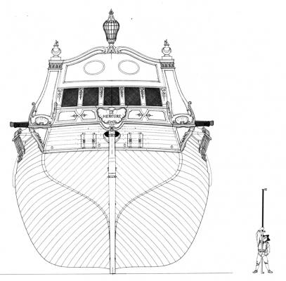
Mark - Thanks for the links. The photos make a good addition to the information from the models in the Musee de la Marine. I am absorbing the French style and learning their rigging techniques. I've also gotten many specific details from three dissertations on the excavation of La Belle at Texas A&M. They are online and make a wonderful reference for late 17th, early 18th century French practice. chj - Thanks for the compliment. Glad you're enjoying it. I am making two copies of the same figurehead. One for each of the two QAR models that I'm making. It is adapted from the lion figurehead in Budriot's plans for Le Mercure. Dan
- 241 replies
-
- 1
-
-
- queen annes revenge
- pirate
- (and 2 more)
-
Mark - I'm back on board and ready to enjoy the journey as you heave the capstan, splice the mainbrace, pay the devil, and all that other nautical stuff. Dan
-
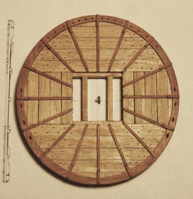
The next deck fitting that I made was the quarterdeck companionway. On Budriot’s plans for Le Mercure it is a raised structure with hinged doors (#24) forward of the mizzen mast (#25) and aft of the watchkeeper's bench (#23). It houses the stairway that leads down to the gun deck and the captain’s cabin. As will be discussed later, I have followed the NMM plans of the Advice Prize for the overall structure rather than Le Mercure. This raises the captain’s cabin to the quarterdeck and eliminates the chicken coop (#27), the whipstaff slot (#26) and the cabinets (#28 and #29). With the changed layout there is some question if the large companionway would still have been on deck if the captain would not be using it, or would it have been more of a simple open hatchway, perhaps with an open railing? The answer is unclear, but since there is some justification for retaining it, I am doing so. Here are Budriot’s plans. I have followed them, except that the strap hinges on the roof have been modified a little to make them stronger. Construction was pretty straightforward. A coaming was built with lap jointed corners in the same way that the hatch coamings were made. Three sides were fashioned with birch planks over a solid sheet to fit inside the coaming. Internal corners were strengthened with square stock and the external corners were dressed up with cherry veneer. A crosspiece was fitted and glued at the top edge of the structure to keep it all square. This is the stage of construction on the right. On the left the two planked sections of the roof and the front doors have been added and the piece is complete, except for a final stain and finish. The bottom of the coaming has been left square unstill it is installed on the slanted and cambered quarterdeck. Here is it from an oblique viewpoint so you can see all the details. The construction techniques are fairly simple and incorporate a number that have been discussed in dealing with prior fittings and structures. The only new technique is for the hinges. I started with 1/16” brass strip (2” wide in scale) and bent one end around on itself using a needle-nosed wire bending pliers. You can get these from dental supply houses, or from your child’s orthodontist. Once it is bent around on itself, it is tightened up as much as possible. Using this strip the smallest eye that I could form was about 0.028” i.d. I decided that this was acceptable in this scale. The hinge strap was pre-drilled for 0.020” iron pins that will secure it to the wood. Here I have marked out the locations of the holes and the strap length for the door hinges. After drilling, the hinge was parted off from the strip and chemically blackened. Here it is installed on the door. You can see the iron pins that go through the door and were clipped off short. The hinge sits on an “L” shaped piece of wire that goes into the doorpost. The hinges for the roof were made in the same way, except that the straps are longer. Two matching hinges were installed facing each other and a pin was epoxied into the outer one with the inner one allowed to rotate freely. Here is the completed companionway with Pirate Pete inspecting its quality. And here it is with the doors ajar, ready for Pete to descend the stairs. It was probably not necessary to make the doors operable, but it is one of those little details that keeps up my interest. I will know that it is there, even if the doors never move after it is displayed in the museum. Be well Dan


- 241 replies
-
- 11
-
-
- queen annes revenge
- pirate
- (and 2 more)
-
Mark - Thanks so much for answering that question. I will have to look harder around the internet to see other examples of the bench. If you can point me to a site or two, that would be great. I linked to your build log of La Licorne, which is much like the QAR and only a little earlier. I was sorry to see that you have abandoned the first version for a second, but I am sure that the next one will be up to your high standards. In the meanwhile, I hope that I can pick your brains again if I am stumped on a detail. Dan
- 241 replies
-
- 2
-
-
- queen annes revenge
- pirate
- (and 2 more)
-
Mark - I got to your log from your response to my question on the log of the QAR. Like all logs when I first find them, I started on page 1 and read forward to the current pages. I was very impressed with all the good work that went into the frames and interior deck details. I commisserated with all the others when you cut your fingers, and cheered, quietly, when you solved the knotty construction problems of the large pumps and the spiled planking. So I was shocked to read on page 32 that you decided to abandon the model. So much great work. I know that it must have been a difficult decision, but if it is right for you, then it is all for the best. I hope you can save a lot of your detail work and sub-assemblies. Best of success with Licorne v.2. Charting your progress from the Constellation and cross-section models to here, I am sure that it will be up to your high standards. I look forward to much pleasurable reading as she rises from the building board. Dan
-
Thanks, Vic. Nicely stated, not understated at all. Thanks too for the likes. This week I got some work done on the hull despite the snow. The wooden plates of the upper hull have been cut and bent to the required shapes. The portion from the stern to the end of the waist is fairly flat, with a consistent 13 degree tumblehome. It was cut, fitted to the rabbet cut into the solid lower hull, and screwed in place. Temporary support blocks were fitted to the inside face which also support the dummy quarterdeck that you can see in the photos. The transom piece has been cut and temporarily fitted in place as well. The bow section is much more complex. In place of the open bow deck with a flat beakhead bulkhead, the ship had a closed bow. At the waist it has the 13 degree tumblehome, but at the cathead it actually has an outward flare as if it were still open. Then when it comes around to the stem it is vertical. To accommodate these requirements, the foredeck corners are bumped out, making it less rounded and the deck overhangs the lower hull. I derived the shape of the quarterdeck from the plans and cut a dummy deck. This was mounted at the correct height on a sturdy block and screwed into the solid lower hull on the centerline. Rough patterns were cut from cardstock and transferred to ¼” basswood, which was cut oversize at the top. Multiple dados 3/16” deep were cut across the pieces, closer together at the tight bend at the corner. The pieces were wet for an hour in a bucket of water, then forced into shape in the hull rabbet and against the dummy foredeck. They were screwed in place and the top line marked out above the foredeck. The pieces were removed and trimmed, then reinstalled and left to dry. This is where you see it in the photos, with a dummy stem piece in place. Although I have never used this method of both kerf and wet bending together in a model hull, it seems to be working out pretty well. Meanwhile, I continued with some of the deck pieces that will be needed. Here is the bench that sits on the quarterdeck for the captain’s convenience. I’ve never seen this before, but Budriot has it on the plans. If anyone has seen such a fitting, I would be very interested. Here are his drawings. And here is how the completed bench looks, with some of the components. The primary wood is birch, with cherry veneer for the accent work and arms. The arms were built up of four layers of veneer stacked vertically. The outer layers of the horizontal pieces for the arm are sandwiched around two vertical pieces for the post. On the right is the arm piece shaped oversize to the desired curve. On the left it has been trimmed to shape. Here is the first one completed from another angle. And here are the finished pair with my scale figures for comparison. I also set up for the four ladders which will connect the gun deck at the waist with the gangways between the quarterdeck and foredeck. They have only four treads but are wider at the base than at the top. As you can see in the photo, my ladder technique is to make a long box from which separate ladders can be parted off individually. Two matching rectangular pieces for the stringers have dados cut across the grain. A web of veneer sheet woods are fit into these slots for the treads. The grain runs across from stringer to stringer. Sorry, this enlargement did not come out too well, but you can see how the dados are cut halfway through the stringer material. The ladder block was set up so everything was square or, rather, symmetrical until the glue hardened. A ladder was parted off on the band saw at the calculated angle, cleaned up, and finished. This angle might not be right, so I only made one to test. Whatever the ultimate angle, the rest of the block should be enough for at least the four needed for the first model. I will need a pair of longer ladders from the quarterdeck up to the poop deck on top of the captain’s cabin, and a wider one from the quarterdeck companionway down to the gun deck. They will be made in much the same way. The companionway itself will be next. Be well Dan


- 241 replies
-
- 14
-
-
- queen annes revenge
- pirate
- (and 2 more)
-
ROYAL CAROLINE 1749 by Doris - 1:40 - CARD
shipmodel replied to DORIS's topic in - Build logs for subjects built 1501 - 1750
Beautiful as always, Doris. Just beautiful work. Could you tell me what adhesive you use to attach the clay pieces to each other and to the model, and how you finish them after installation. There is never a trace of glue around the tiny parts. Thanks. The helmsman is looking good too. The hat will be a nice touch. Since this is a royal yacht, and there are high-ranking people aboard, I think that he would be dressed in his best uniform most of the time. Dan- 883 replies
-
- 1
-
-
- royal caroline
- ship of the line
- (and 1 more)
-
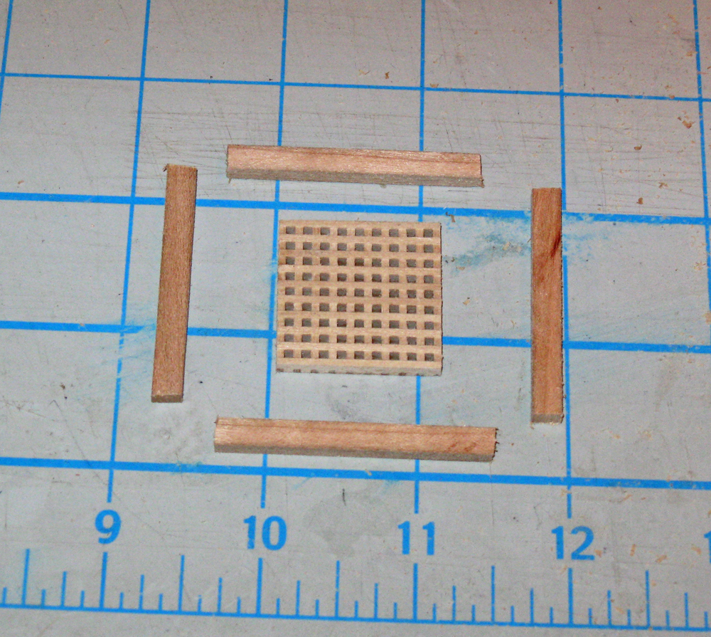
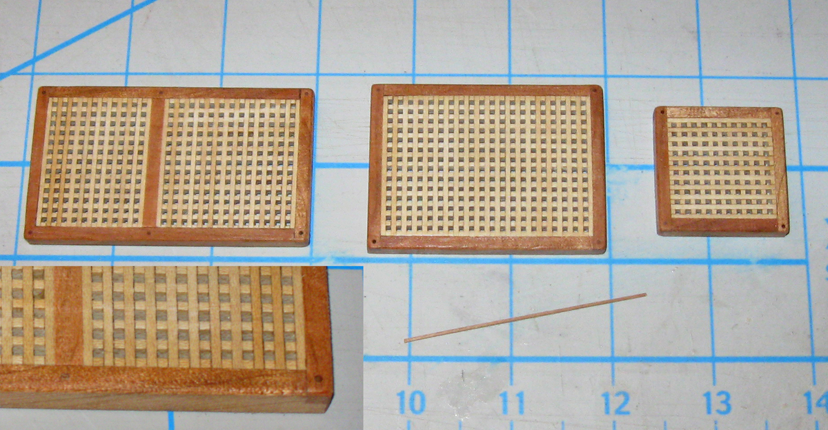
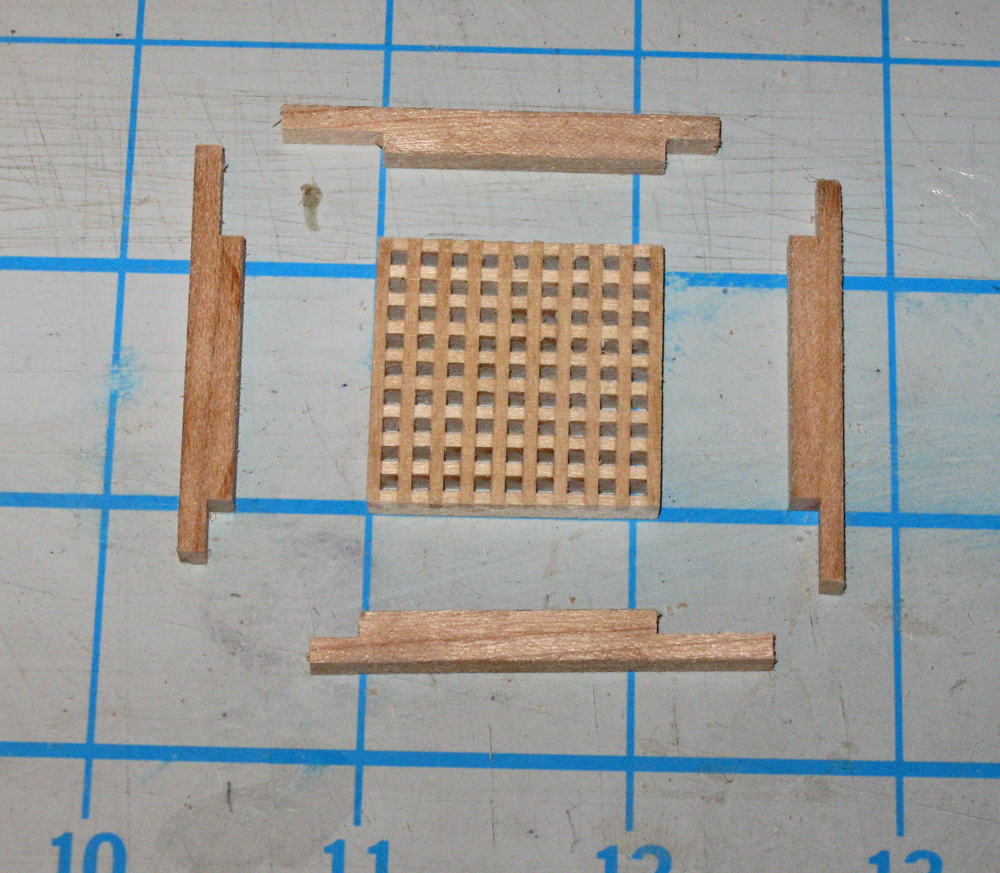
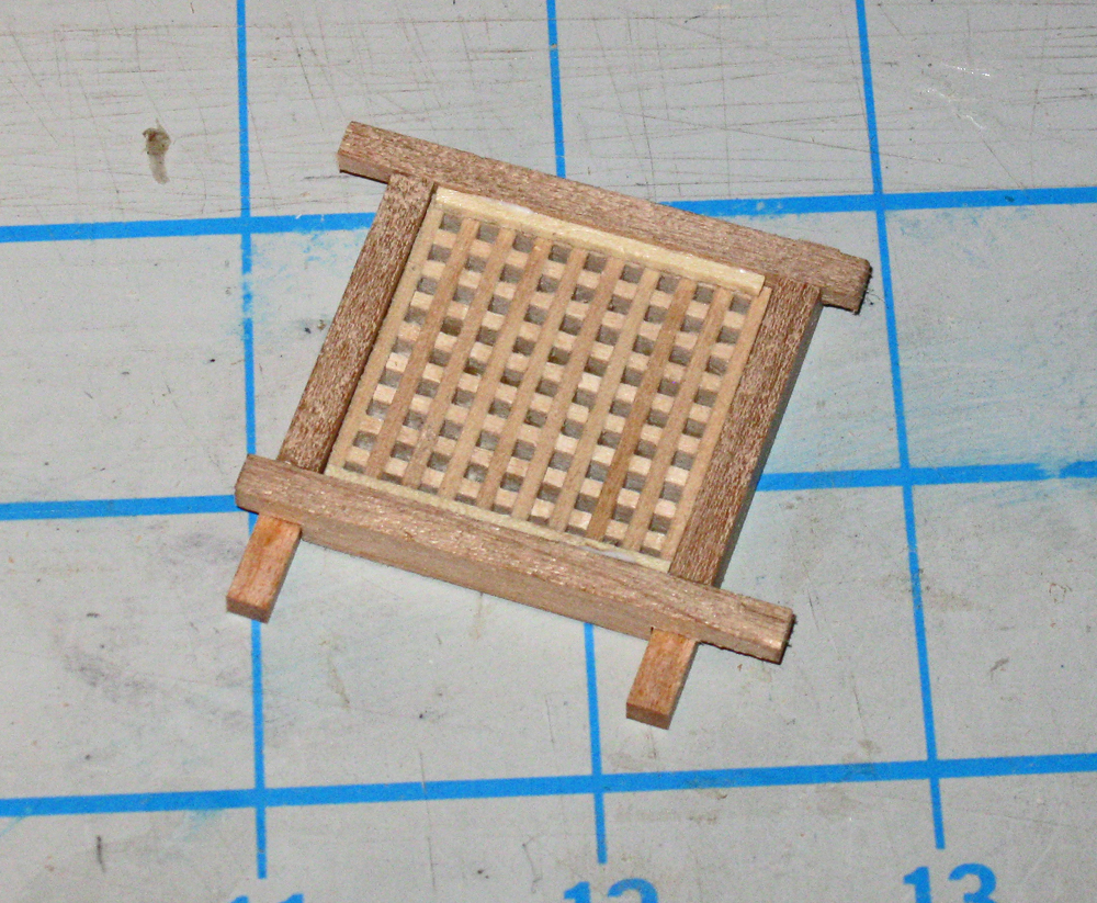
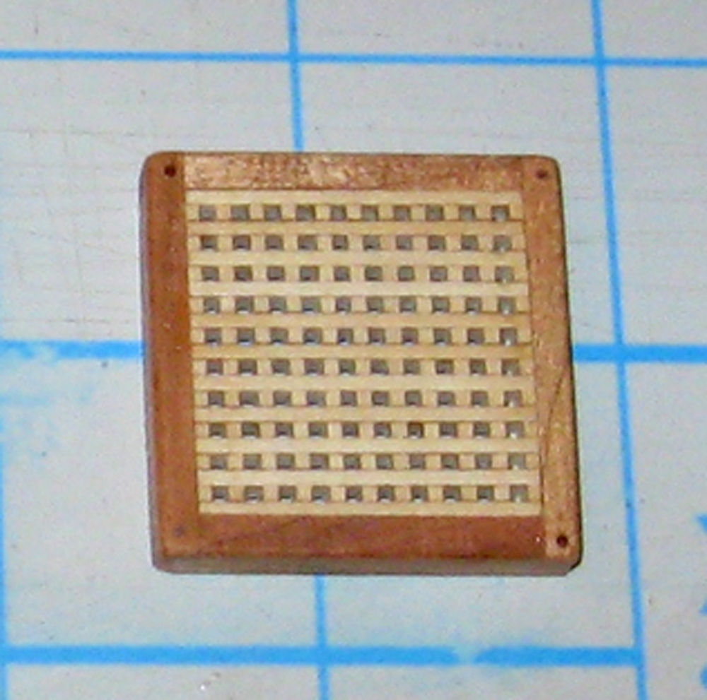
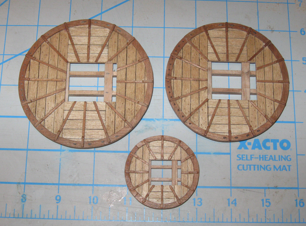
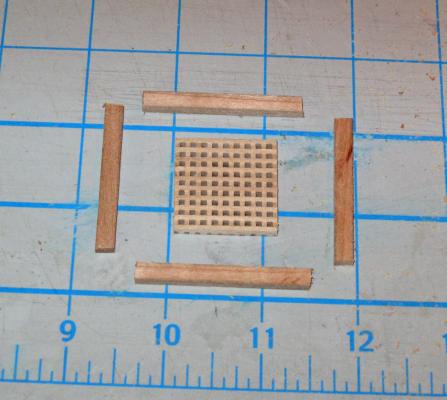
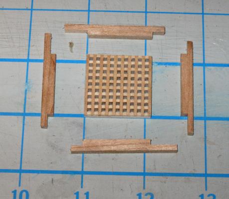
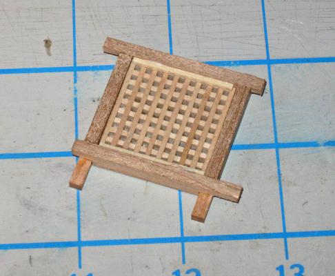
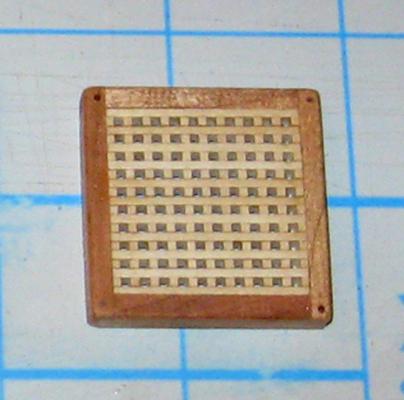
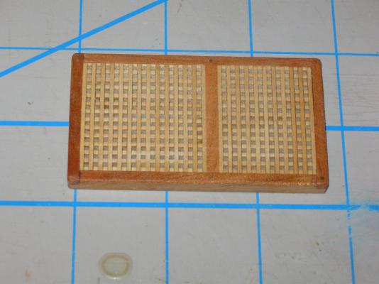
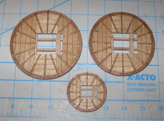
Hello again – I got some time during the football games to write up the next installment. I hope you enjoy it. With the grating sheets made, I made the coamings. My method here also relies on the table saw and uses no measuring with a ruler. This time it is based on the specific grating to be framed. I make the coaming to fit the grating rather than the other way around. I get a much tighter fit that way. Here is a piece of grating that has been cut from a sheet. The edges have been sanded flush and it has received a first finish coat to protect it from any glue stains. It looks square, but it is slightly longer than it is wide. As mentioned, the grating material is poplar. For contrast I selected cherry for the coaming and cut stock 1/8” x ¼”. Four pieces of coaming stock were cut longer than each side of the grating piece. They will be joined with half lap joints at the corners. The table saw blade height is set so cuts made from the top and bottom of the coaming stock just meet in the middle. One end of each piece has a half lap cut into it. The length does not matter as long as it is longer than the thickness of the coaming stock. First, the shoulder was cut using the rip fence as a depth stop. Then the lap was made by making multiple passes moving away from the fence to nibble away the unwanted wood. A spacer strip was located that was wider but shallower than the lap that was cut. Using the spacer and the grating piece the fence was set for the shorter sides. A sacrificial stick supports the coaming piece as the shoulder for the second half lap is cut. The coaming piece was turned around and the unwanted wood from the second lap was nibbled away. The matching short piece was done, then the saw was reset and the longer pieces were done in the same manner. Using the grating piece itself to hold the pieces square, they were test fit, adjusted as needed, assembled and glued. When the glue was dry, support pieces were glued to the inside edges. Doing only two sides is enough. If you want the grating to be removable just make sure that the supports are glued only to the coaming. Here I have glued the grating in place permanently. The corners were trimmed, the piece was turned over and sanded smooth, and all edges and corners were eased. The bottom edges are left raw and will be sanded to the curve of the deck when installed. The piece was finished with matte varnish. And here is the set of three for one of the QAR models. In the insert the lap joint is clearly visible. The joints were also treenailed for strength. Two diagonal corners of each coaming were drilled but not filled. During assembly longer treenails will go through them and into the deck for security. A length of treenail stock is packed with the set ready for final assembly. As you can tell from the brevity of the text, this all goes quite quickly with a some practice. All of the work making the six hatches and gratings took only a little more than a day. Doing the photographing and writing these build log entries took longer. I hope that this was instructive and provides another technique to add to your tool box. Be well Dan


- 241 replies
-
- 19
-
-
- queen annes revenge
- pirate
- (and 2 more)
-
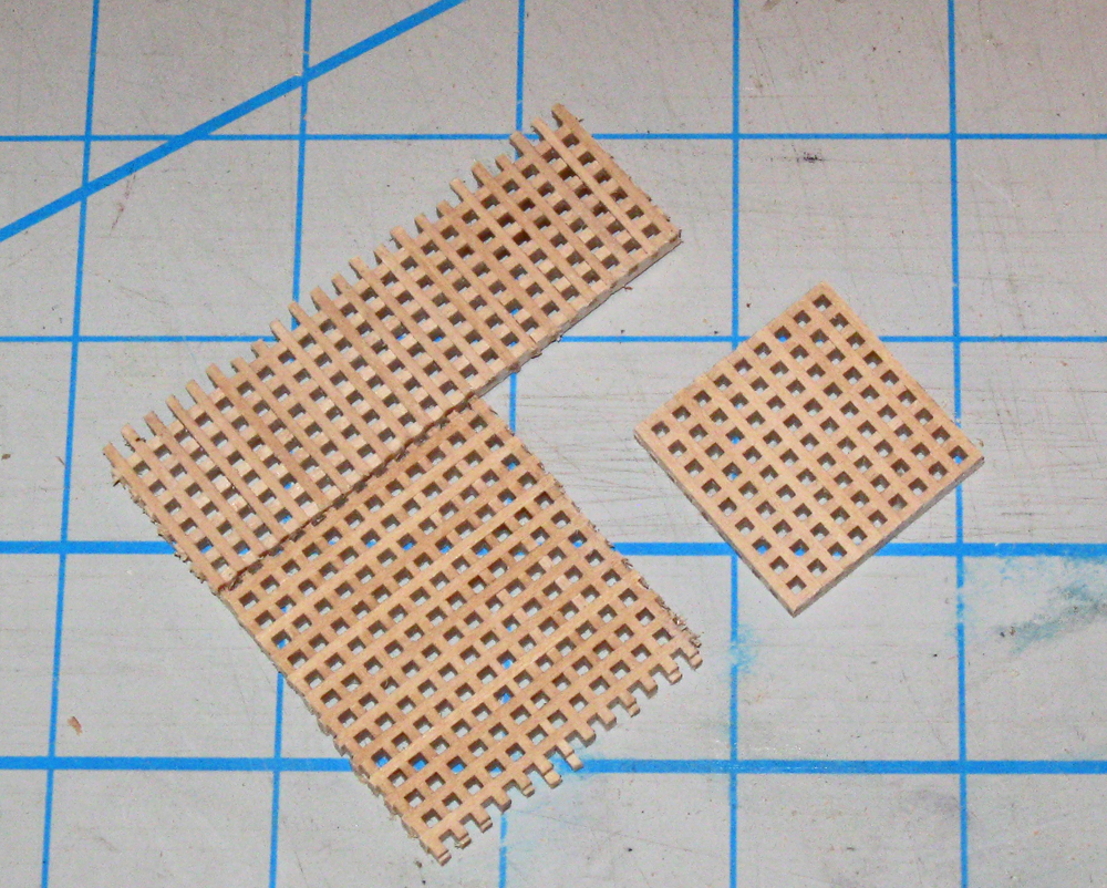
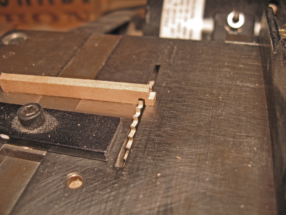
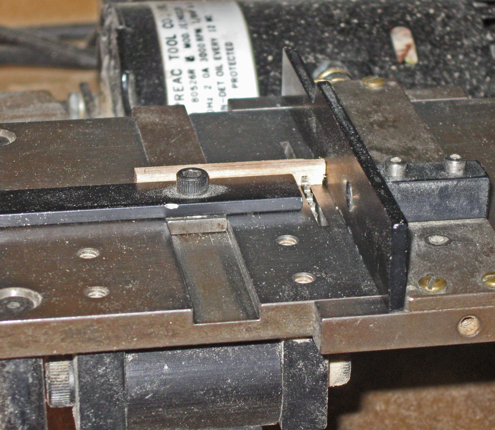
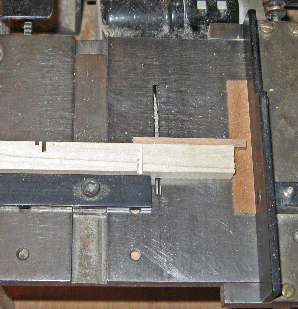
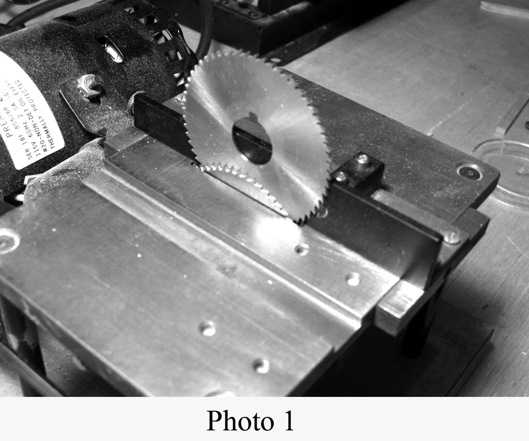
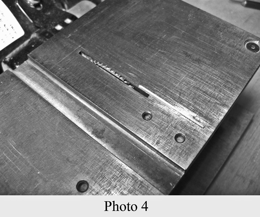
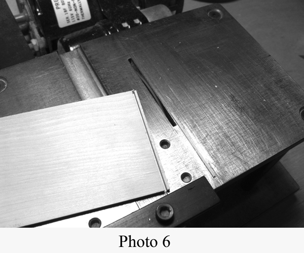
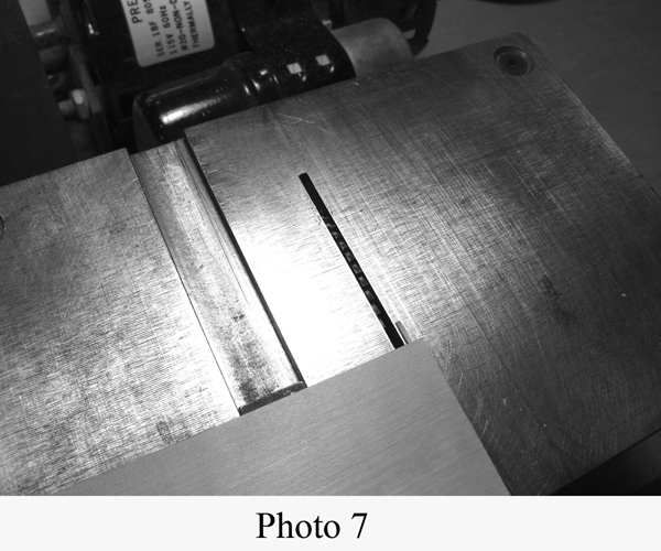
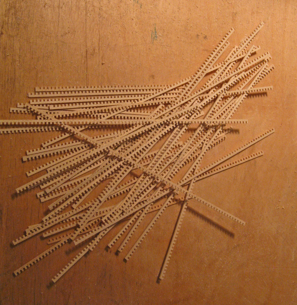
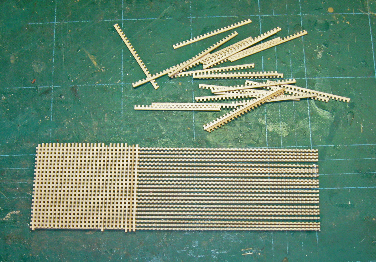
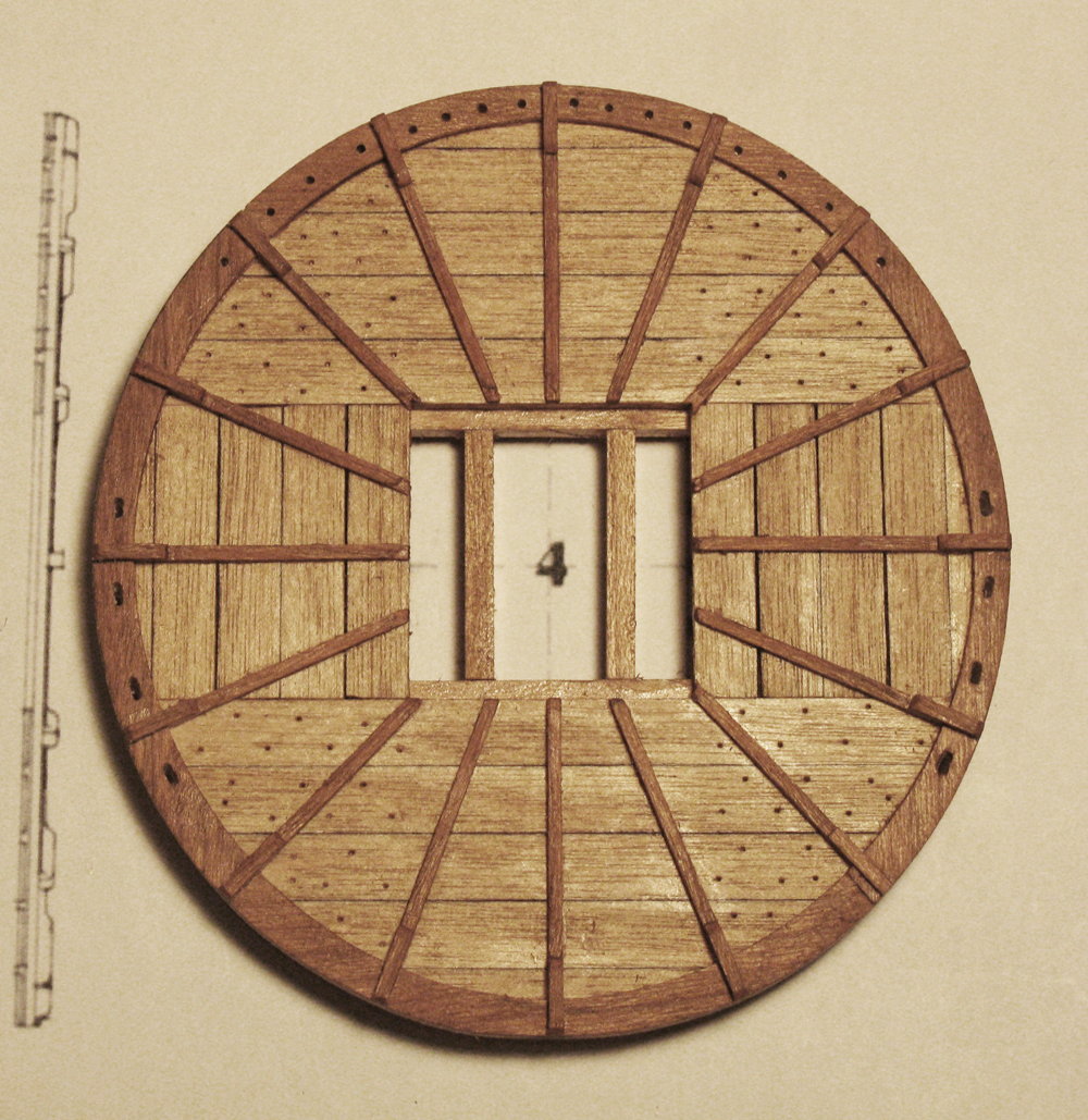
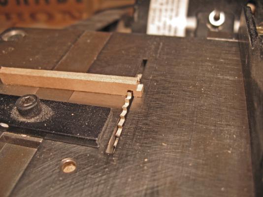
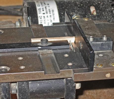
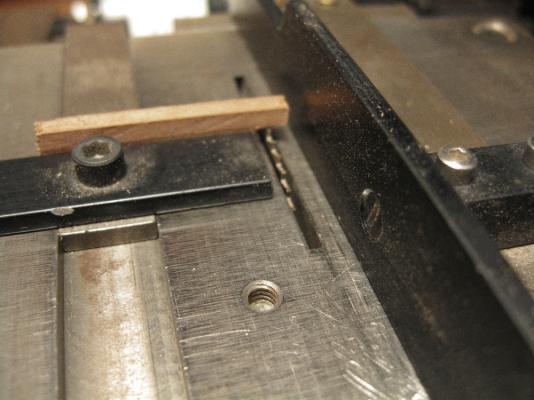
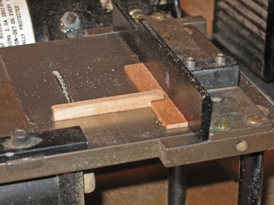
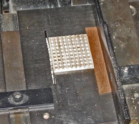
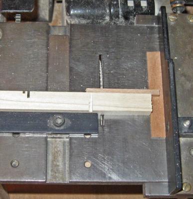
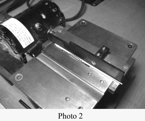
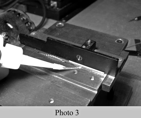
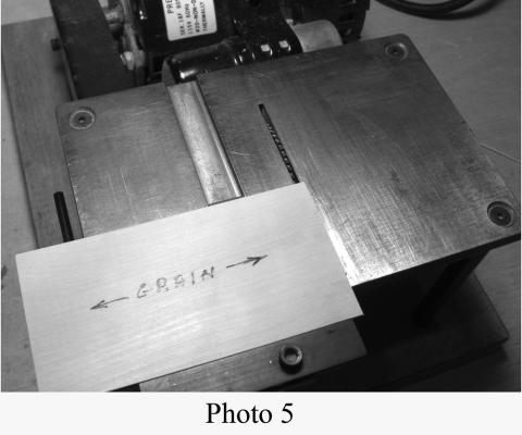
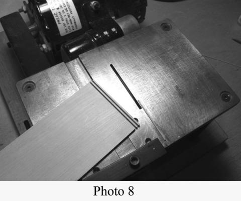
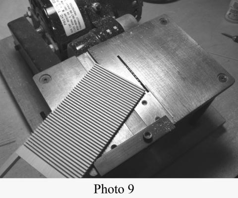
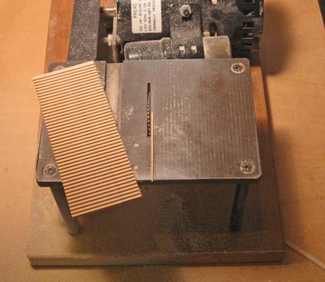
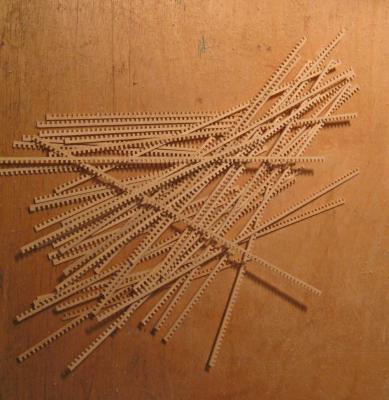
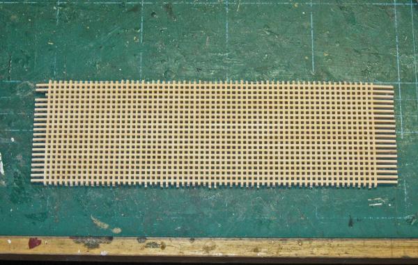
Hi all, and thanks for the comments and likes. The next set of independent pieces to be made were the three hatches with gratings. One two-part one goes on the quarterdeck, while the other two go on the gun deck under the boat in the waist. My method for making gratings is a bit unusual in that it there is little or no measuring done with a ruler or calipers. Everything is done relative to the thickness of the saw blade that is used. I developed this method because I only have a Preac saw. A milling machine might make the whole process easier, but I work with what I have. The first thing is to set up the saw to make square section sticks of wood whose dimension will be about 2 inches in the scale being used. This then has to match the thickness of a saw blade that you have. For the small grating I used a slitting saw blade that was 0.032” thick. To set the saw I sandwiched that blade between a second blade and the rip fence. The fence is snugged up and locked down. The cutting blade does not have to be the same thickness, although in this case it was since I have two blades of that same thickness. [These first nine photos are in black and white because they are taken from another presentation on making much smaller gratings]. Several sticks 0.032” square were cut from a sheet of hardwood. Only a few are needed. Then the blade that matches the sticks is mounted in the saw, if it is not already there. Two of the sticks are sandwiched between the blade and the fence which is snugged tight and locked down. One stick is removed and a short section of the other is held firmly against the fence and tacked in place with extra thin cyano. Care is taken to see that the fence is not glued to the table. The fence is removed, leaving a guide strip parallel to the blade and one blade thickness to the right. A rectangular piece of hardwood sheet is selected and held against the guide strip and the miter guage. The blade height is set up to cut just a tiny bit deeper than halfway through the sheet. The wood is run over the blade, cutting a channel one blade thickness from the end. The wood is flipped over and the slot that was just cut is placed on top of the guide strip. The wood is run through again, cutting a second channel two thicknesses to the left of the first channel. The balance of the sheet is cut in the same way, making a series of channels parallel to each other and spaced two blade widths apart. Here is the grating sheet for the QAR. At my scale I needed sticks and channels that were about 0.055”. I took one of the 0.032” blades and stacked it together with a 0.023” blade, making a 0.055” dado blade. Actually, for the small grating I used Portia Takakjian’s technique. This involves cutting lots of square sticks as well as cutting cross channels across the first ones. The cross channels are filled with the sticks and everything is glued together. When dry the solid back of the sheet is ground off with a sanding drum. This works well for a small grating, but the wider blade did not cut as cleanly so I kept getting tearout. Also, I needed more than 25 square inches of grating and did not look forward to grinding off so much wood. Instead, I removed the guide strip and set the saw to cut 0.55” using the blades as spacers again. Strips were parted off the sheet until the material was used up. I call them toothed strips for obvious reasons. Three quarters of the toothed strips were cut into thirds and interlocked with the remaining long strips. This created a grating sheet about 2 ½ by 7 ½ inches. This was only enough to make the gratings for one of the models, so a second grating sheet was made in the same way. From the sheets I cut out sections for the grating sizes that I needed, sanded the edges flush and gave them a coat of slightly darkened matte finish to protect them from glue stains when the coamings get built around them. Overall, this method worked well for me, and I will try it in smaller scales in the future. A tip of the hat to Charlie Files, inventor of the Preac, wherever you are. I will have the log of making the coamings in a few days. Until then, be well. Dan


- 241 replies
-
- 19
-
-
- queen annes revenge
- pirate
- (and 2 more)
-
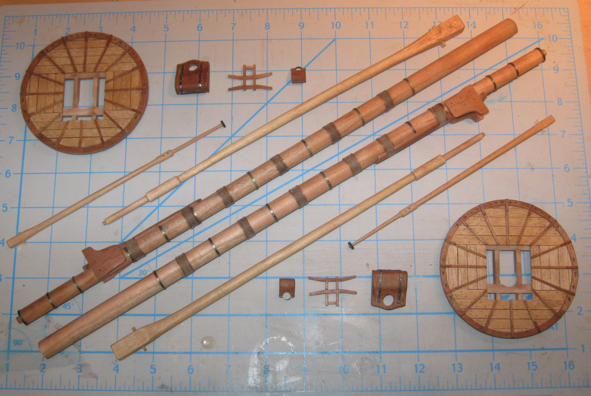
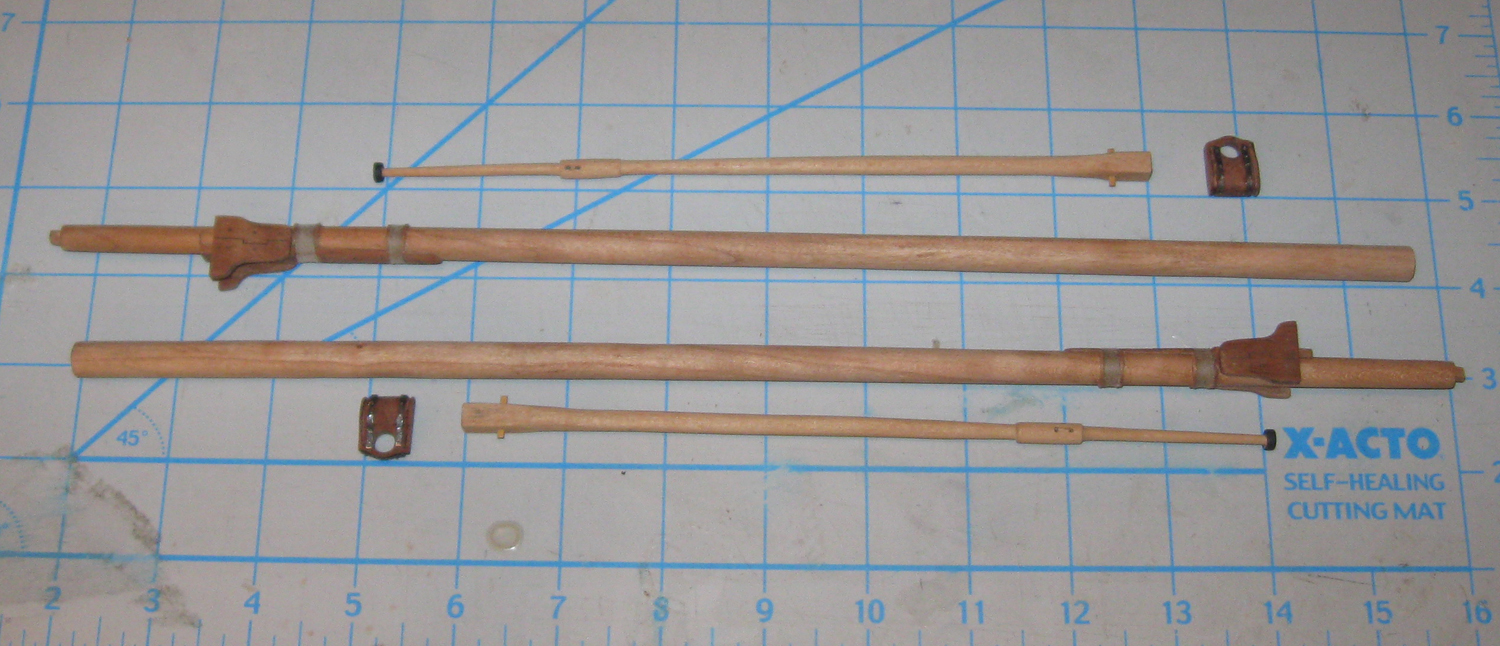
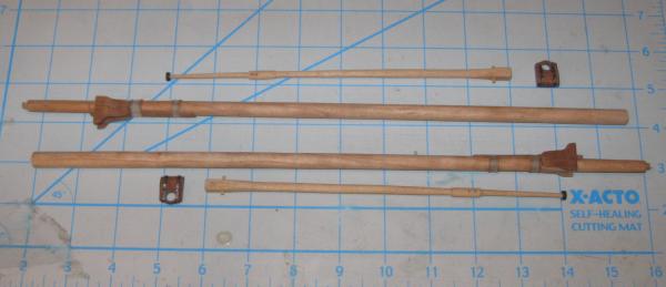
Hello and Happy New Year to all - This past month has been full of grandkids and holidays that got in the way of what is the most important thing in life - ship modeling I did manage to complete both sets of the masts, which are packed away until rigging time. The fore The mizzen And the Bowsprit and jib boom Meanwhile, I have been studying the rigging diagrams and reading Anderson and others. The first question came when I realized that some of the lines, including the halyards, run from the mastheads to belaying points on deck at the base of the mast. To do this they have to pass through the platform of the top. Budriot's plans and the tops that I made from them have no openings aft of the masthead. I figured that I could solve this in one of two ways - I could simply drill some holes for the lead of the lines, or I could take apart the tops and remove some of the planking to make a larger opening, a much more complicated procedure. I consulted with some knowledgable modelers including Rob Napier, and Bob Giles sent me some photographs of the tops of the St. George (1701) model at Annapolis. I also looked at the photographs of the model of Le Sans-Pareil (1757) in the Musee de la Marine. All of them agreed that removing the planking was the only way to go. So, with some anxiety, I pried off the trestletrees and crosstrees from under each of the tops. Fortunately they came away with only one slight greenstick fracture that was easily repaired. The cleats were shortened, then I used a razor saw to cut through the plank aft of the lubber hole. The enlarged opening was cleaned up with a blade and sandpaper before the trestletrees and crosstrees were cleaned up and re-attached. Here they are. Next, the gratings and coamings. I have worked out a new way to do them which gives me better results in this larger scale. Be well Dan


- 241 replies
-
- 12
-
-
- queen annes revenge
- pirate
- (and 2 more)
-
Hi Daniel - and Happy New Year - Coming along nicely at such a small scale. Budriot's plans show a very tall stern with two banks of high windows. That does not fit with the Advice Prize draught, so I lowered the transom in Photoshop and got this. Perhaps it will be of some help to you. Be well Dan
-
Coming along very nicely, Ron. It looks like it will be a Happy New Year for you. Dan
-
ROYAL CAROLINE 1749 by Doris - 1:40 - CARD
shipmodel replied to DORIS's topic in - Build logs for subjects built 1501 - 1750
Welcome back, Doris - Seeing your work again was a wonderful Holiday present. Like Floyd's wife, mine has become jaded with all the "ho-hum" just another ship model, but she is always eager and excited to see your postings and the beauty of your work. She thanks you too. Be well Dan- 883 replies
-
- 2
-
-
- royal caroline
- ship of the line
- (and 1 more)
-
Hi Ron - Coming along very nicely. The symmetry and the evenness of the reveals is well done. Looking forward to seeing it completed. Dan
-
Hi Ron - As Remco says, you have to start with some pretty wide stock to get the proper spiled shape for the final planks. And with clinker planking you don't have the freedom to make adjustments the way you do with carvel hulls. I found it incredibly useful when I was building the hull of the Thames River Skiff to cut each plank shape out of cardstock before committing to wood. I generated a lot of scraps, but learned where the difficulties were going to be and what wierd shapes I needed to get a fair hull with even and consistent reveals from plank to plank. Best holiday wishes to you and yours. Dan
-
Hi Michael - Excellent clean and precise work, as usual. I was wondering what the scale height of the fife rail is from the deck. It looks to be no more than a foot (assuming the belaying pins are about 18" long).. Would this be a useable height? I am not familiar with real boats like this, so it certainly could be right. It just looks strange to me compared with fife rails that I know from earlier ships. Dan
-
Hi Daniel - I think that the most definitive history of the ship has been done by the team at the North Carolina Maritime Museum which is excavating the ship underwater in Beaufort Inlet. They, along with the North Carolina Department of Cultural Affairs, has commissioned a number of researchers and enlisted any number of grad students, here and in France, to comb the records to see what can be found. It appears that she was built in or around 1710 to the plans of a small French frigate as a privateer for a French merchant family to be used during Queen Anne's War (1708-1711). Once the war ended the family went into the slave/privateering trade. The ship would leave France for the west coast of Africa to pick up slaves, transport them to the French posessions in the Carribean, then return to France, picking up any prizes she could on the way home. On her third slaving trip she was captured by Blackbeard. All this and much more is in the report written by Mark Wilde-Ramsing, PhD, which incorporates much of that research and his own doctoral dissertation. You can find it here http://wayback.archive-it.org/org-67/20120515002435/http://www.qaronline.org/techSeries/QAR-R-09-02.pdf This doesn't change a lot from your conception of the ship, but I hope it is of some interest. I'll be looking forward to your progress. Happy Holidays to you and yours. Dan
-
Daniel - Add my compliments to all the others. Really nice work at a really small scale. I agree with your color choices although I might have gone with a brown/natural look for the sides of the hull. QAR had been a slaver for several years before being captured by Blackbeard, and I don't think that slave ship owners would waste money on paint, and pirates even less so. It's a real help for me to see someone else's conception of the ship as I work my way through the masts and fittings. A very Merry Christmas to all . . . Dan
-
Ron - You do all that great work without a table saw? My hat is definitely off to you. I could not function without my Preac. Dan