shipmodel
-
Posts
941 -
Joined
-
Last visited
Content Type
Profiles
Forums
Gallery
Events
Everything posted by shipmodel
-
 Hi Michael - Glad you are enjoying the log. The wire was nothing special, just some 28 gauge (about 0.020") soft iron from the hardware store. 100 feet cost under $4. Since they were all removed and discarded after the first four strakes were installed, I used whatever came to hand easiest. Dan
- 241 replies
-
- 1
-

-
- queen annes revenge
- pirate
- (and 2 more)
-
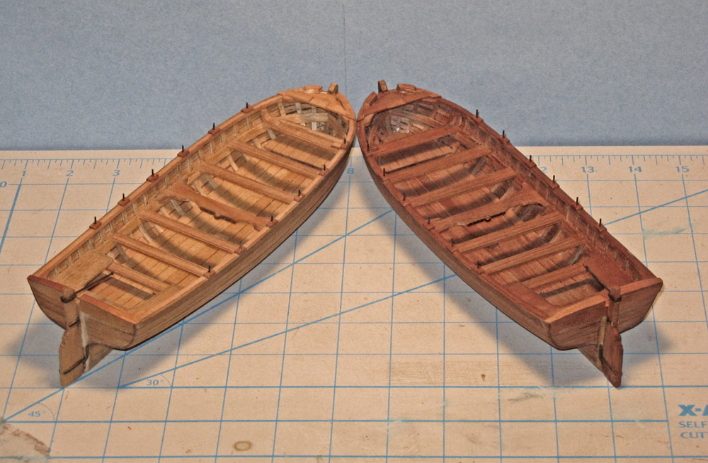
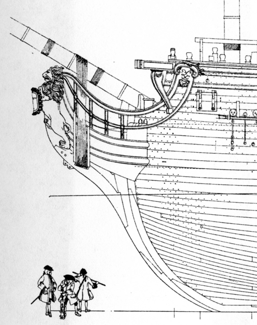
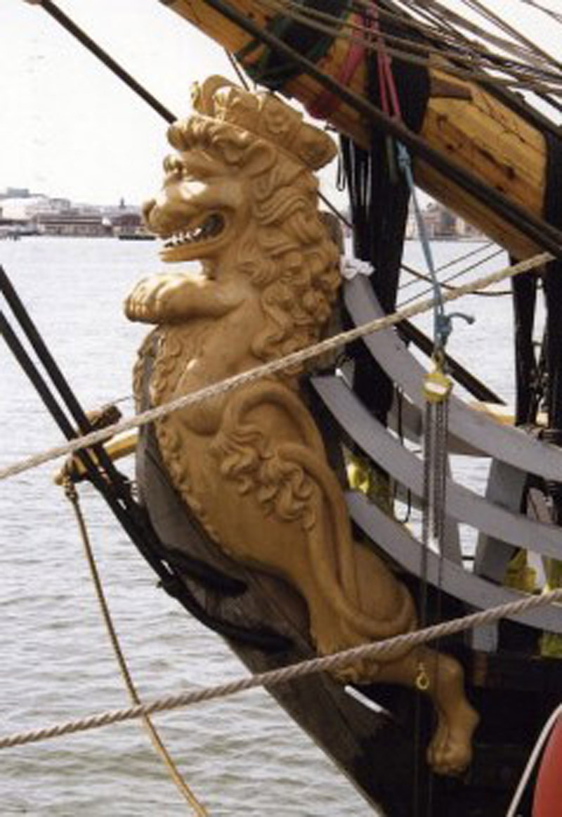
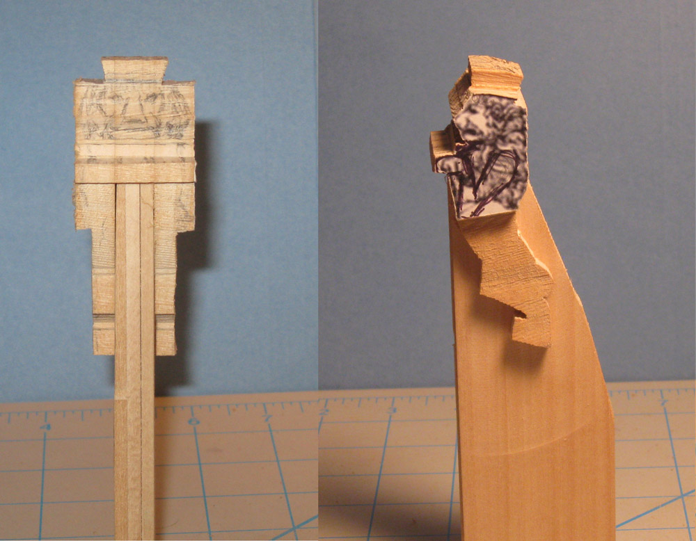
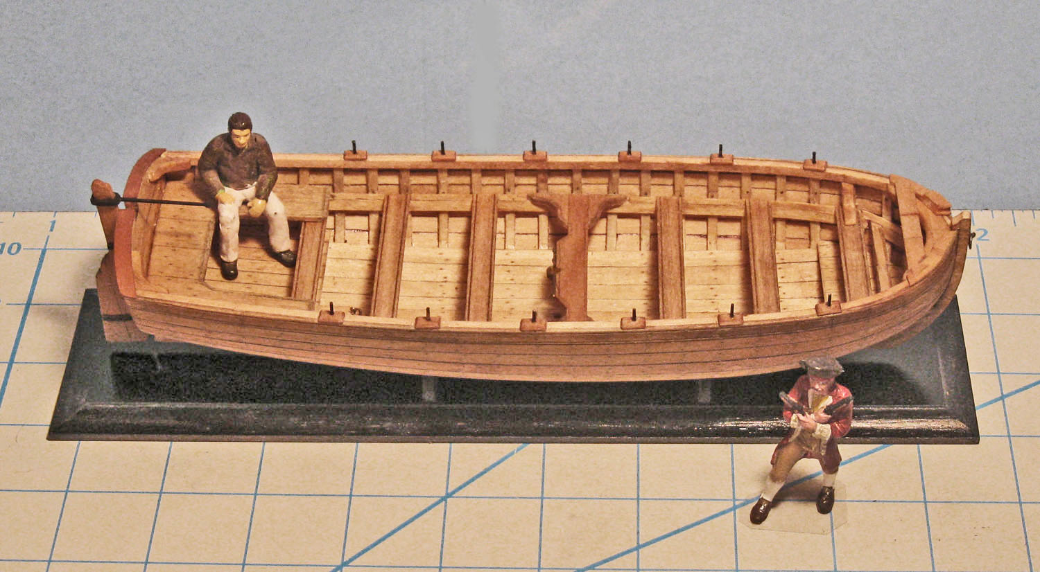
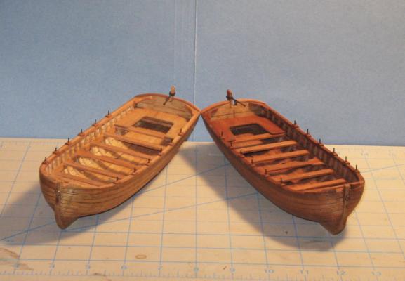
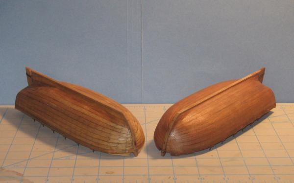
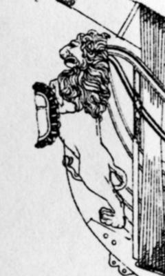
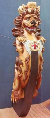
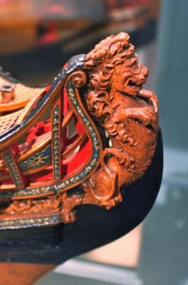
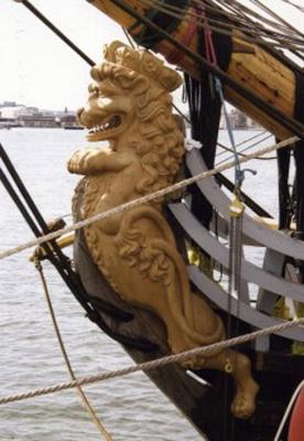
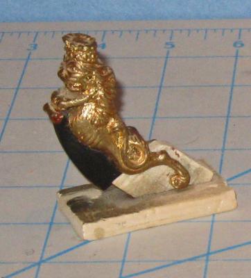
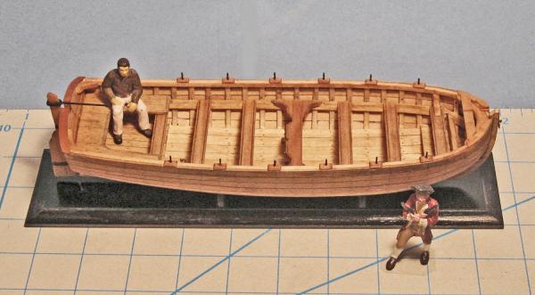
Hi again - Good to see and talk to some of you at the NRG conference. Had a good time and the speakers on Saturday were great. Not much to report. A good deal of work went into doing the second boat, but it replicates the building of the first one, so it was not the subject of a build log entry. Here are the two, side by side. The second was made of cherry, so it is much darker than the first. Since they will be on separate models that will not be displayed together, they do not have to be identical. I actually prefer the first. The lighter color of the wood lets the caulking and fastening details stand out a bit more. But the darker one is closer to the color of old, unpainted boats that I have seen. I won't get to work on the hulls for another week, so I am starting on the figureheads. The Advice Prize draught does not have a figurehead of any kind. Although the actual ship probably did, the Admiralty was not interested in decorations. They just took off the hull lines so that later English ships could benefit from any foreign design advances. Budriot has a lion for Le Mercure, shown here. This is going to be the basis of my figureheads, but a number of others are being studied. Here are three from models in the NMM collection. All of these are too florid and intricate, I believe, for what would have been a pretty basic ship. I am also studying the lion that was carved for the Gotheborg replica ship. Finally, I am using a cast lion fitting from a ship model company that I used to own. It is the wrong size so I can't simply cast two duplicates, but it should be a good carving aid since I can turn it in my hand to get any view that I want. Construction began with three pieces of hard pear wood glued together. All are 3/8" thick, with the outer ones much longer than the middle one, forming a channel that is the width of the stem. A properly sized copy of the Budriot lion was printed out and glued to one side. The basic outline was then cut on a band saw. The saw marks gave me horizontal landmark for the eyes, nose and mouth and they were pencilled in. The lower body is narrower than the mane, so some of the wood was band sawn off. The crown was similarly defined in a rough way. A false stem of basswood was made which has a tight friction fit between the lion's legs. It will act as a handle and will support the fragile feet and legs as the carving progresses. Next time the carving begins. Be well Dan


- 241 replies
-
- 7
-
-
- queen annes revenge
- pirate
- (and 2 more)
-
Nice save with the new tool. When I saw the first photo I could not imagine how you were going to get the clay removed from the inside walls of the bottle. There are some intricate tools developed by Ralph Preston for bottling models that you can read in Ship Modelers' Shop Notes II from the Nautical Research Guild. The articles may give you some ideas. Ralph is one of the top ship-in-a-bottle modelers in the US. Dan
-
HMS Sussex by mij - Scale 1:48
shipmodel replied to mij's topic in - Build logs for subjects built 1501 - 1750
Mij - That's what we pay for rubber cement that we use for the same purpose. Just another example of how we are two countries divided by a common language. Dan -
HMS Sussex by mij - Scale 1:48
shipmodel replied to mij's topic in - Build logs for subjects built 1501 - 1750
Hi Mij - Frames looking good. I will be following your progress with interest. Is there a reason for using Copydex? I looked it up and a 125 ml bottle (about 4.25 oz) costs almost $50, which is way more than any other adhesive that I know of. I also looked up the Proxxon long neck tool, since it looked like it would be useful in shaping the solid hulls that I am building. But it was a bit pricey and the reviews were almost uniformly negative. Let us know what your experience is after you have used it for a while. Dan -
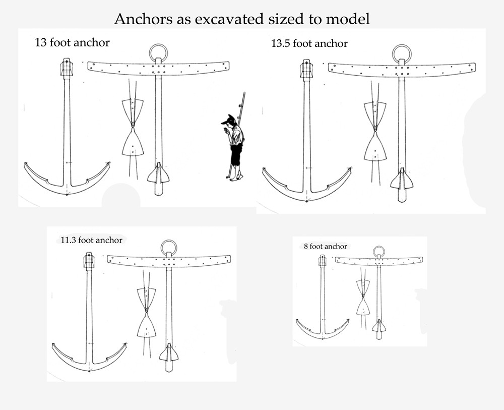
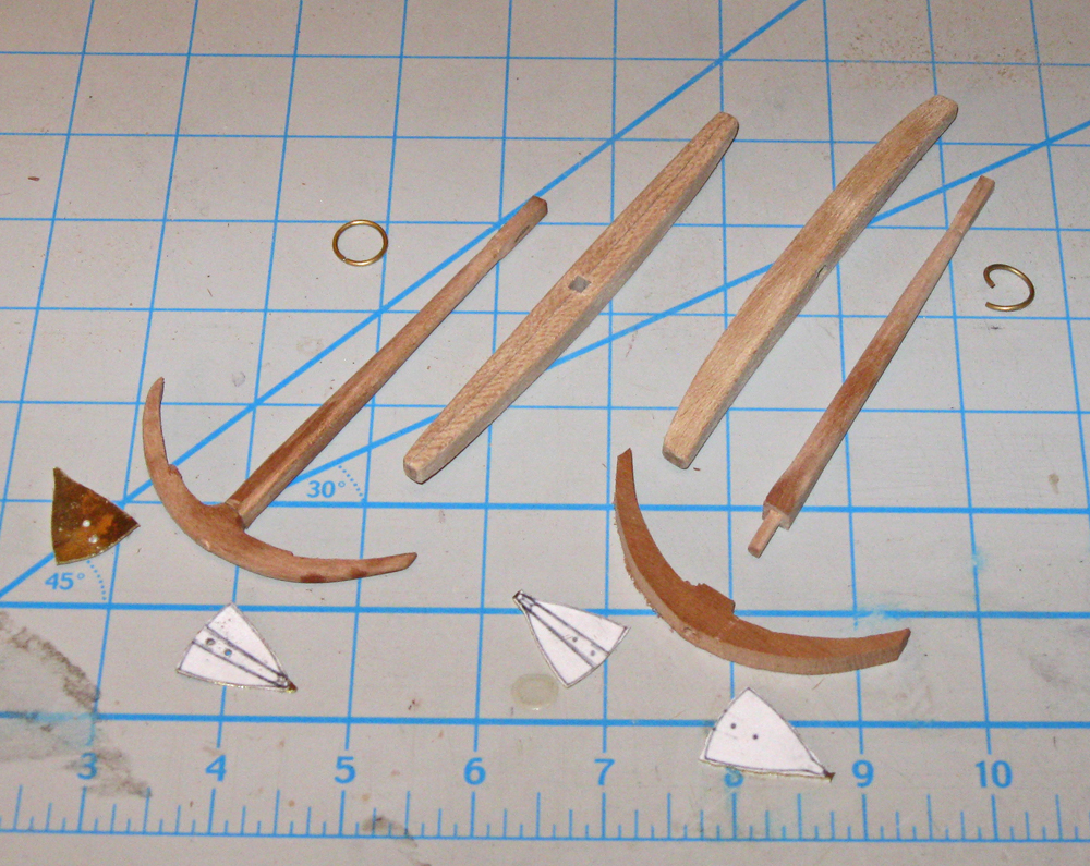
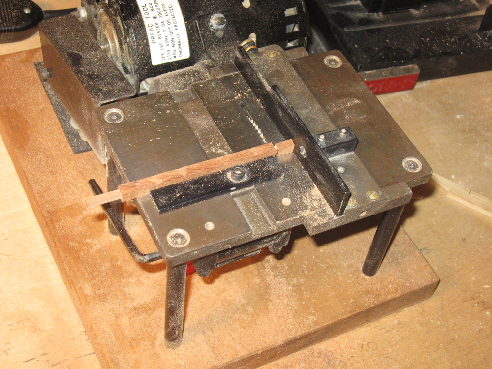
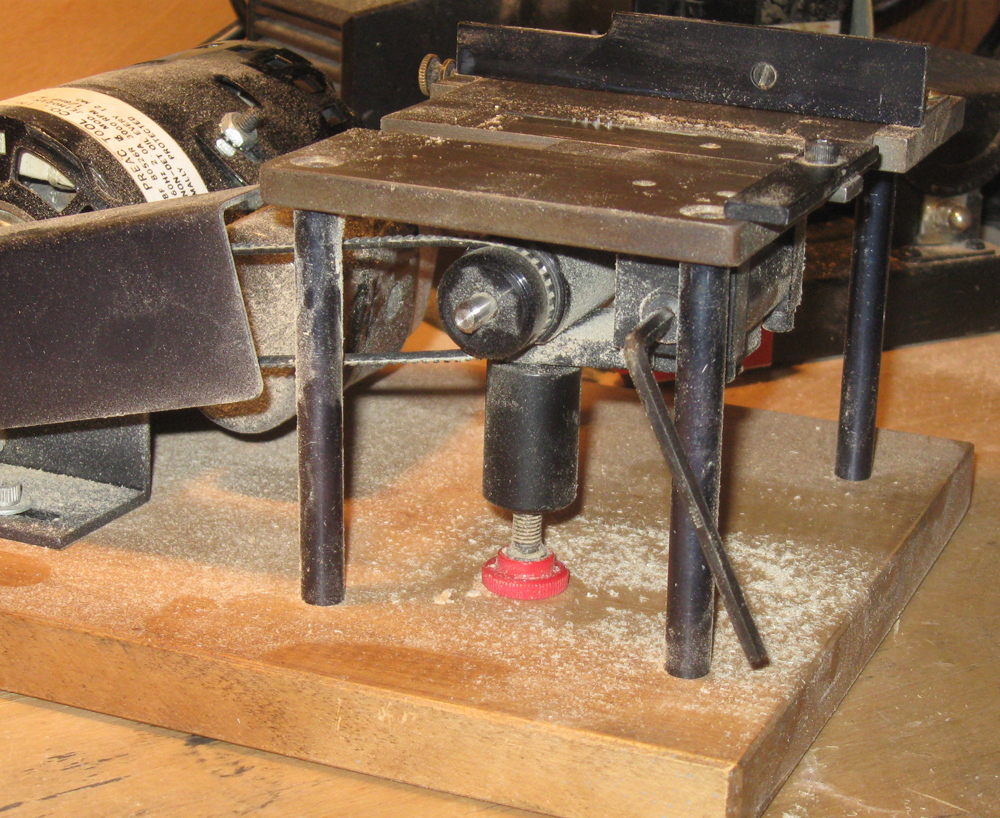
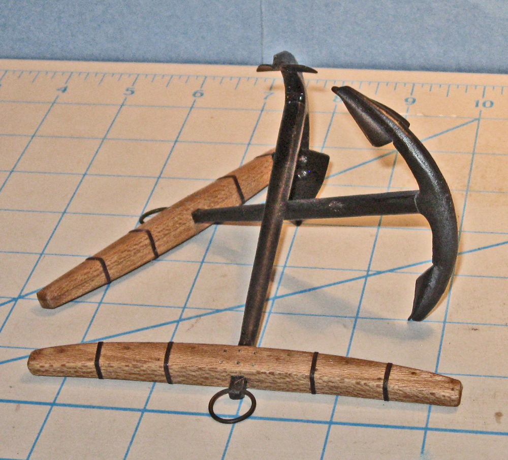
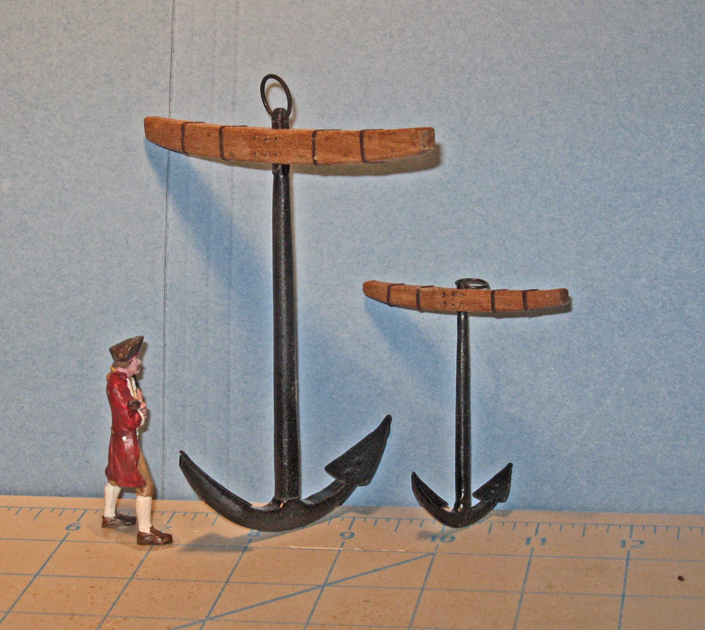
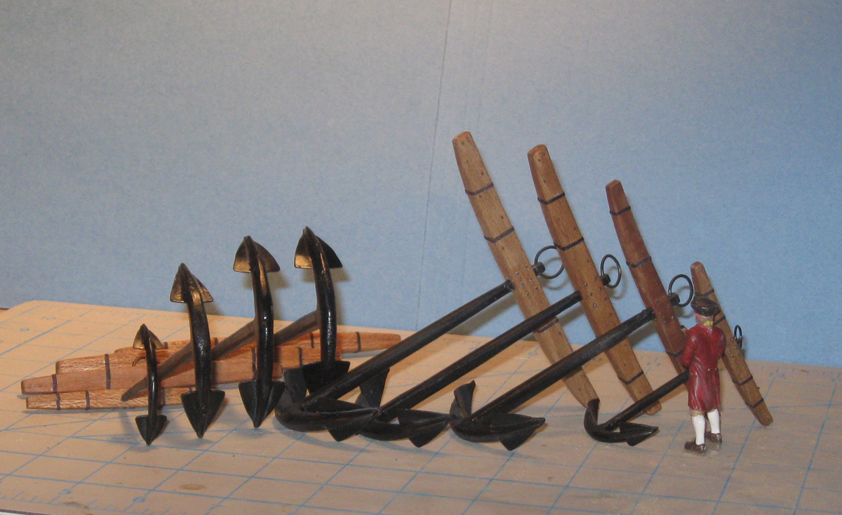
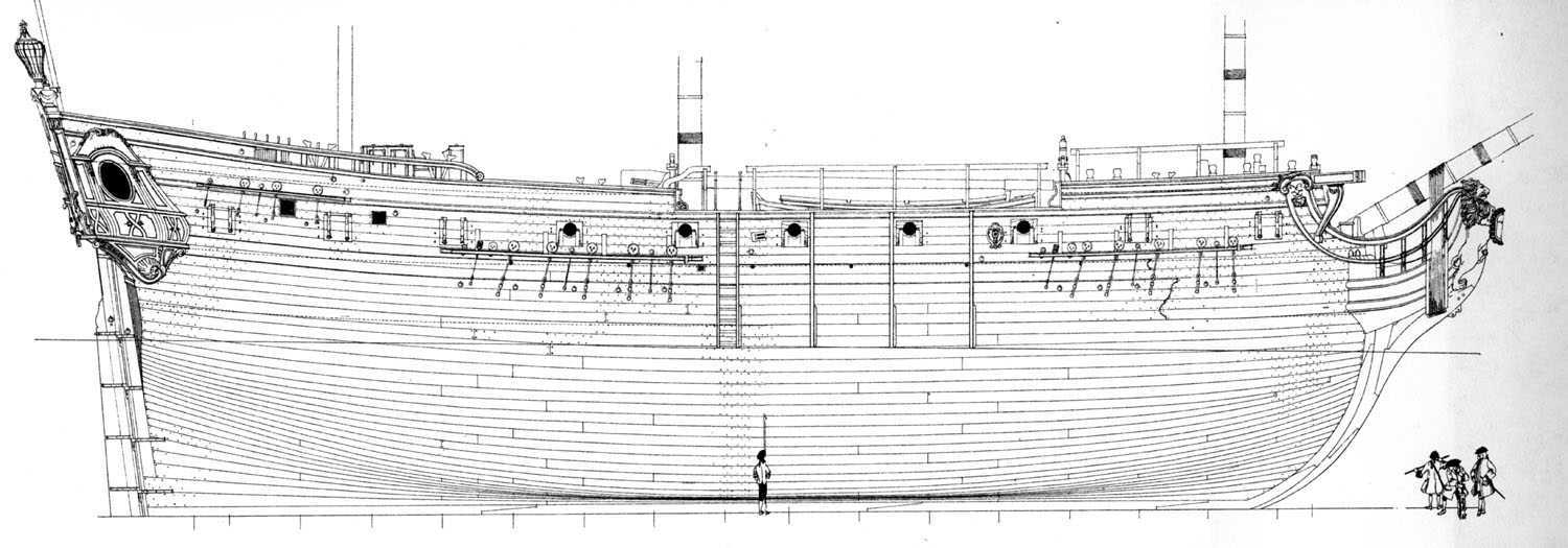
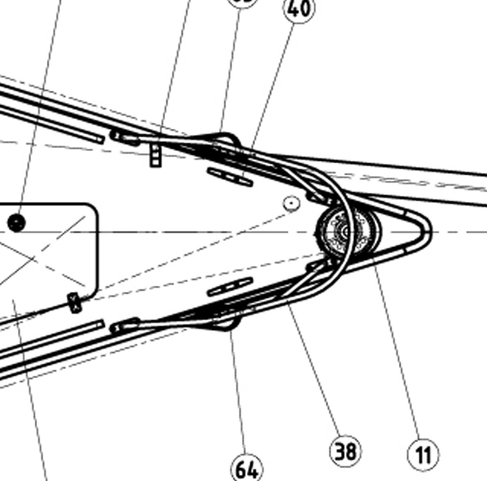
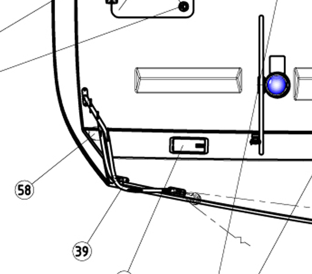
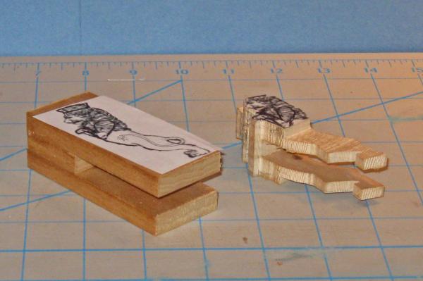
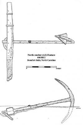
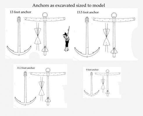
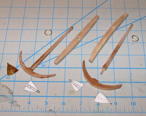
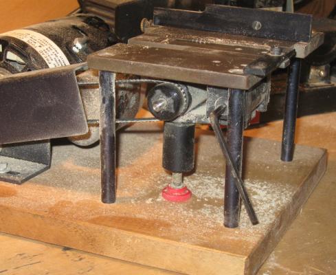
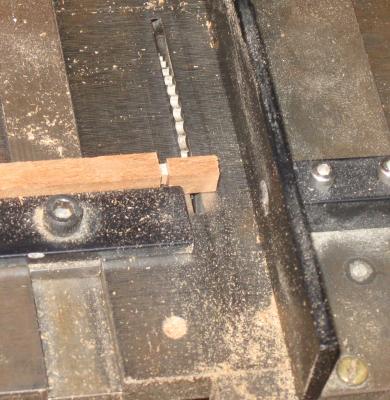
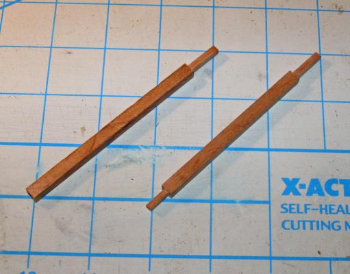
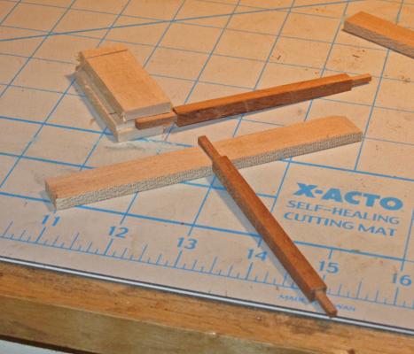
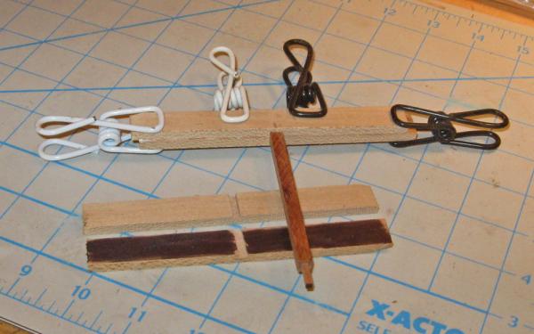
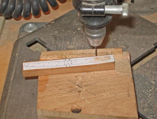
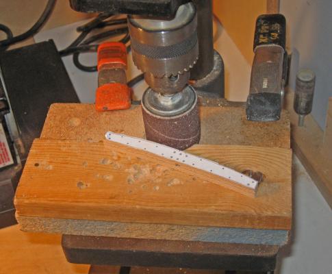
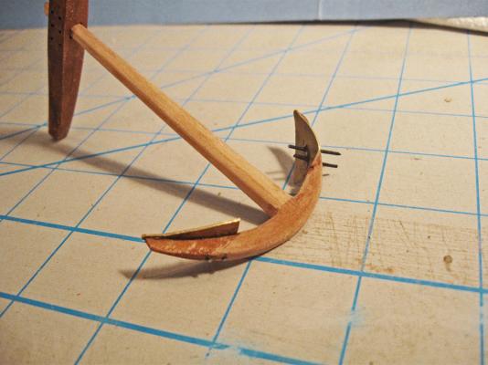
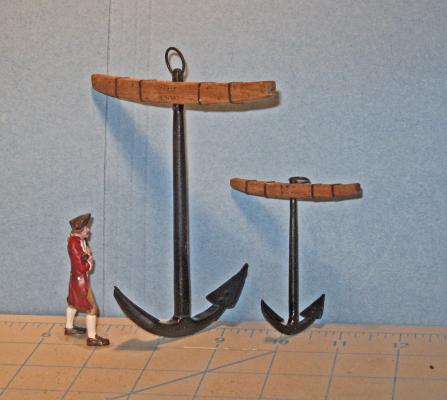
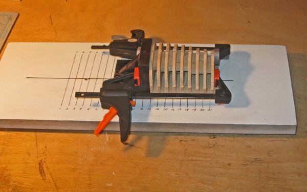
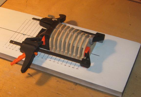
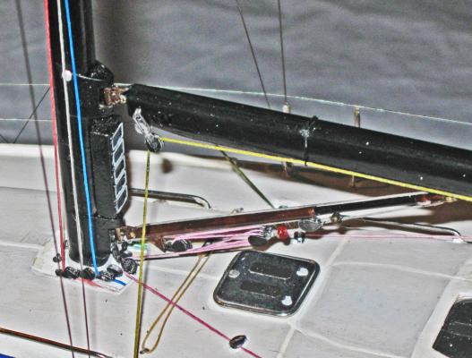
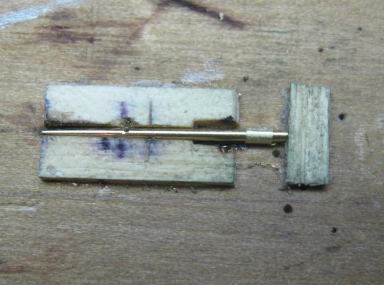
Hi all – Here is the latest installment of the build log. No pirate talk, just building - - - Some work has been done on the hulls since the last build log, but not enough to show. Instead, the next of the independent subassemblies was completed. These are the anchors. Queen Anne’s Revenge carried four anchors of different sizes, all of which have been discovered. They range from the largest, with a shank length of 13 foot 7 inch and a weight of 3,141 pounds to the smallest at only 8 feet and 642 pounds. The others had shank lengths of 13 foot and 11 foot 4 inches. Here is the archeological drawing of one of them. Image 1 Budriot has drawings of several sizes of anchor for Le Mercure, but the drawings are all identical other than size, and none quite fit the ones discovered. I took his drawing and sized it up or down in Photoshop to make drawings that fit the sizes needed. Image 2 An anchor is a fairly simple construct, with only a few parts: the shank with its arms and the flukes pinned to the arms; the wooden crosspiece called the stock, and a metal ring through the shank above the crosspiece. Here they all are for a pair of 11 foot anchors. Image 3 You can see that they are in various stages of completion. The wood used here is pear, throughout. I did not cast the shank/arms because there were 4 pair of different sizes rather than 8 of the same size. It would have taken longer to make 4 masters and then cast them. The first piece to be shaped is the shank. A piece of pear was cut on the Preac saw to a square cross section of the appropriate size and then cut to length. The drawings show that it had a square head where it went through the crosspiece, then became round below the head, which widened and returned to square with rounded corners where it mated with the arm for the flukes at the throat. A round tenon at the foot was secured through a hole in the arm piece. I first milled the tenons on either end. This is easily done while the wood is still square. Here you can see the setup on the Preac. The miter guage is used to keep the wood square to the blade and the fence is used as a depth stop. Image 4 The height of the blade is set by using an adjustable fitting that sits under the hinged blade holder. It is a screw in a wider sleeve with a red plastic cap on the end of the screw. The hole in the bottom of the sleeve conveniently fits around one of the bolt heads on the blade unit. It is a cumbersome and fiddly arrangement, but I am used to it after 20 years. Image 5 To cut the tenon I set the blade to the desired height, testing by making passes on a piece of scrap basswood. I first cut the shoulders of the tenon, then nibbled away the rest of the wood using a wide blade. The final pass is always sideways across the top of the blade to smooth the side of the tenon. Image 6 The final result is a perfectly centered and square tenon on each end of the shank blank. The tenon that will go through the fluke arm piece is narrower than the head tenon and will later be rounded by trimming the corners then twisting it through progressively smaller holes in a drill plate. Image 6a With the head tenon cut the square hole in the wooden crosspiece has to be cut to match. This is possible because the stock is built up from two pieces. Again using the Preac the blade was adjusted till the cut was exactly half the depth of the tenon. I tested this by cutting grooves in two pieces of scrap that when mated allowed the tenon to fit smoothly but not too tightly. You can see this in the upper part of the photo. Below it is the first side of the stock with the tenon fit into the channel that was milled out. Image 7 And here you can see how the two stock pieces fit together around the tenon. Image 8 With the channels cut the side of one of the stock pieces is colored with black ink and the pieces are glued together and clamped using one of the shank pieces to locate and match the pieces. Image 9 After the glued dried the drawing of the stock was cut from a printout of the sized drawing. I used Scotch Spray Mount to temporarily attach it to the stock blank. With the blank still having a square face the holes were drilled for the treenails and bolts that were used to hold the two halves of the stock together. (You may notice that this piece does not have a square hole for the shank. I forgot to take a photo during construction, so this is a scrap piece made up later for the log). Image 10 The stock was cut close to its profile on the band saw and then smoothed using a sanding drum in the drill press since I do not have a spindle sander. Image 11 The rest of the construction is pretty straightforward. Going back to the photo of the pieces, you can see that the sides of the stock were tapered as shown on the drawings and the treenails inserted and sanded smooth. The shank was fitted to the arm piece and both were smoothed to shape and to fit together at the throat. This was done with the tenon just friction fit in the arm piece. image 3 repeat Once the throat joint was smooth the arm was removed and a step was cut into it for the heel of the fluke. The flukes were cut from 0.025” thick brass sheet, ground to final shape, and then peened to a shallow dish form. They were fitted to the arms and pinned through using iron wire which was clipped short and peened on both ends to rivet the fluke to the arm. Image 12 The stock was given its four iron strapping bands and a coat of stain. The final wood selected for the stock was beech, which looks remarkably like oak in this scale. The shank was painted matte black and was fitted to the stock. The six bolts at the center of the stock were made from iron wire cut a little proud of the surface and filed smooth but not flat. The cut ends will age over time to a generic metallic look that will contrast with the look of the treenails. The ring is made from brass rod that was wound round a dowel, clipped and flattened, then chemically blackened. Here is the completed 13 foot pair. Image 13 Until I built these anchors I had little idea how large they really were. Compared to my scale figure the 13 ½ foot anchor is massive, and even the 8 foot one would have been a handful. The entire set of four anchors weighed over 8,000 pounds. Image 14 Image 15 I’m off to the NRG conference next week, so it may be a bit until my next posting. Until then, let me know if you have any questions about my methods and/or my madness . . . Dan


- 241 replies
-
- 13
-
-
- queen annes revenge
- pirate
- (and 2 more)
-
Hi Toni - Just found your log and read it cover to cover. Really nice work with great dedication to getting it right. I will be using some of your techniques to improve my own work. For bolt heads I use soft iron wire, clip it short and file it round, as you do. I may get a set of the cup burrs since you like them. They are shiny when new, but by the time I am done with the model they age and tarnish to a dull generic metallic look that I like. Will you be bringing Atalanta to Charleston? Love to see her in person. Dan
-
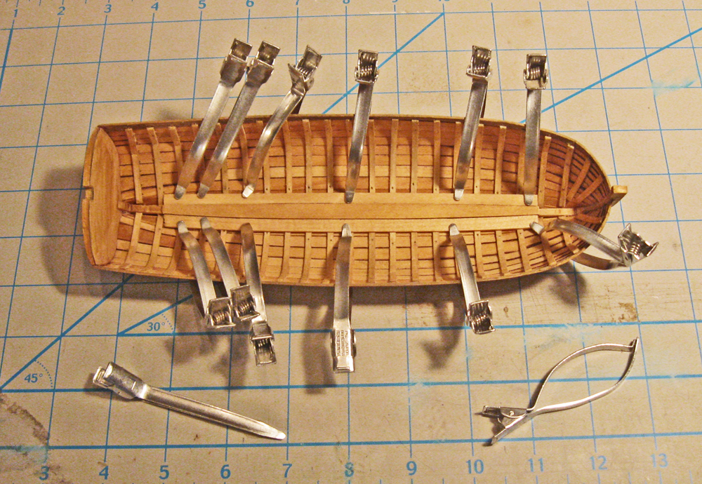
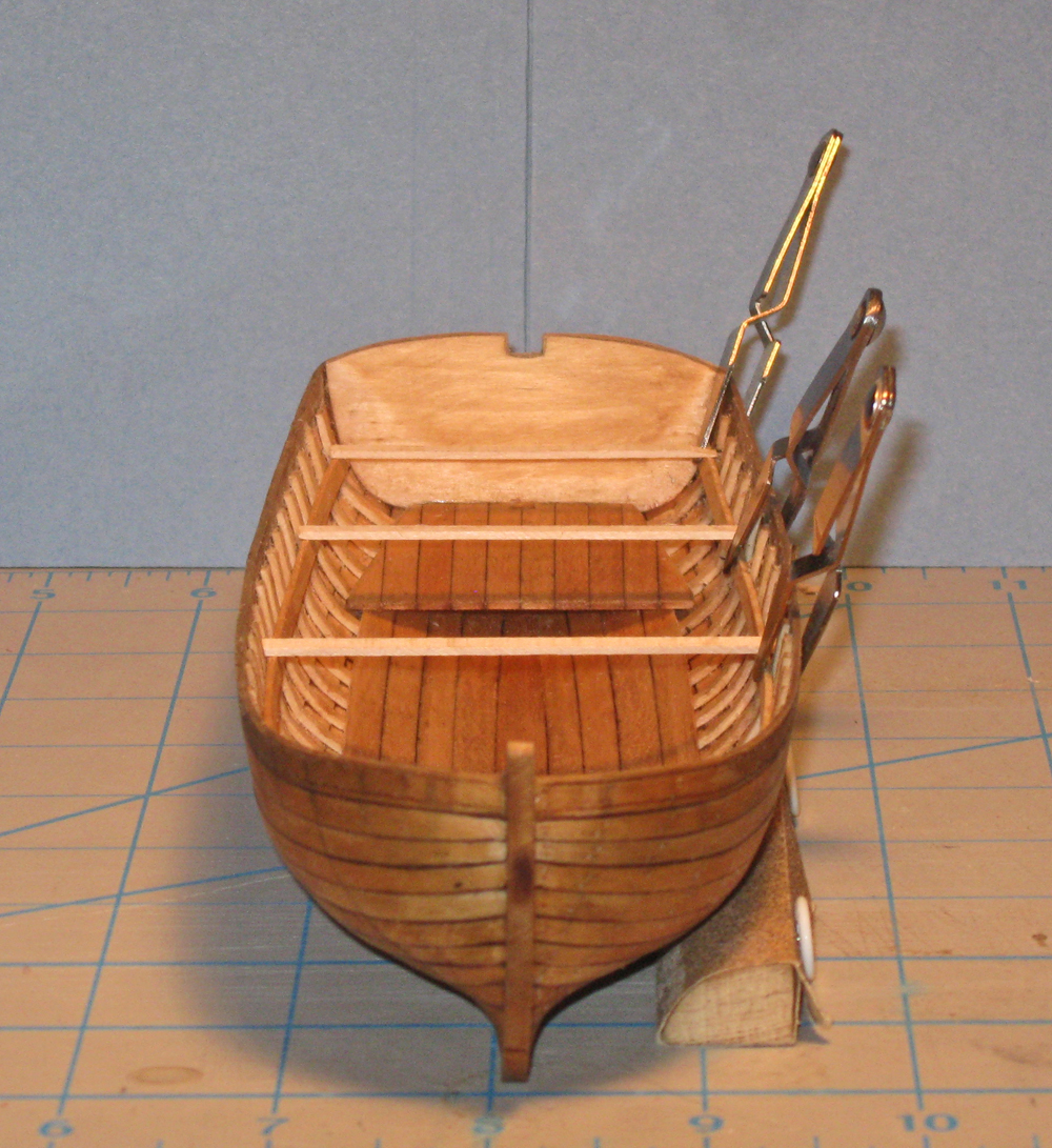
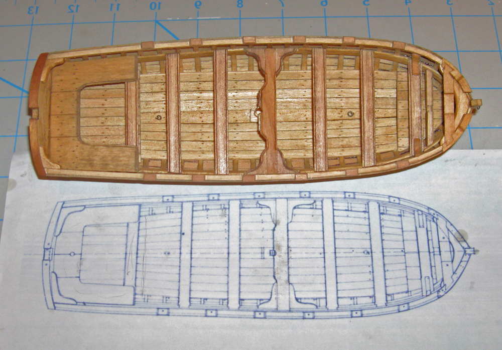
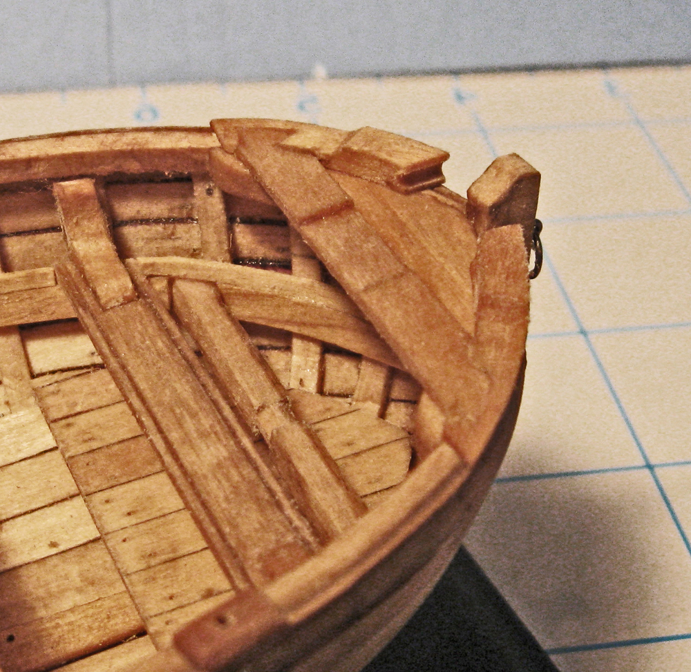
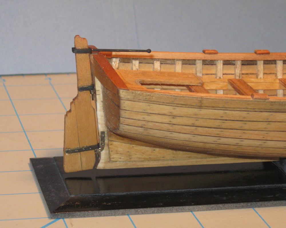
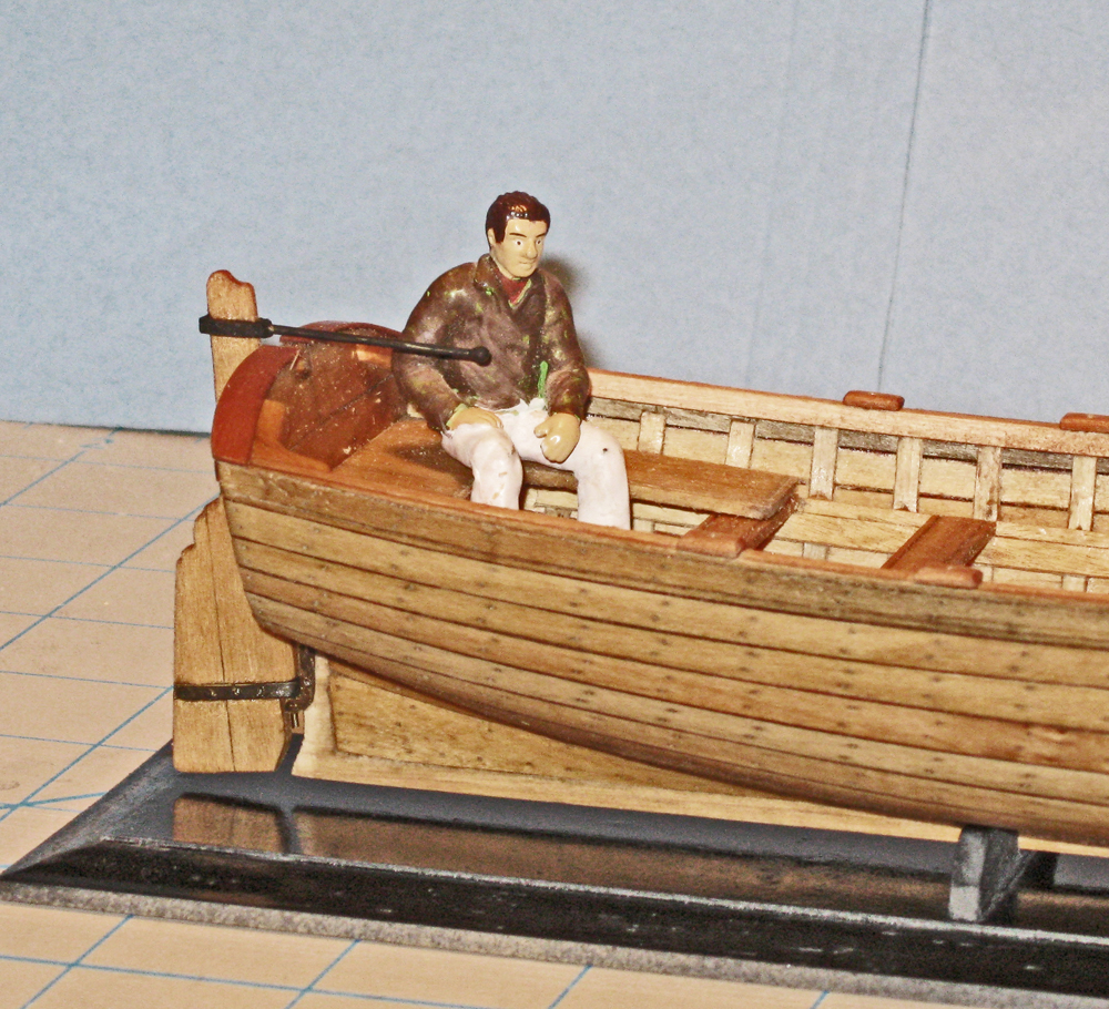
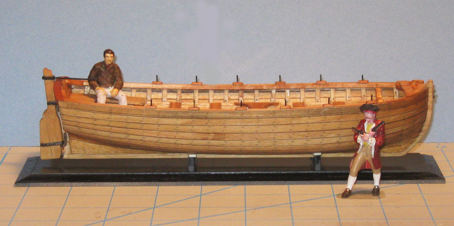
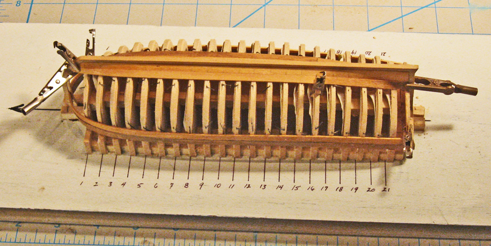
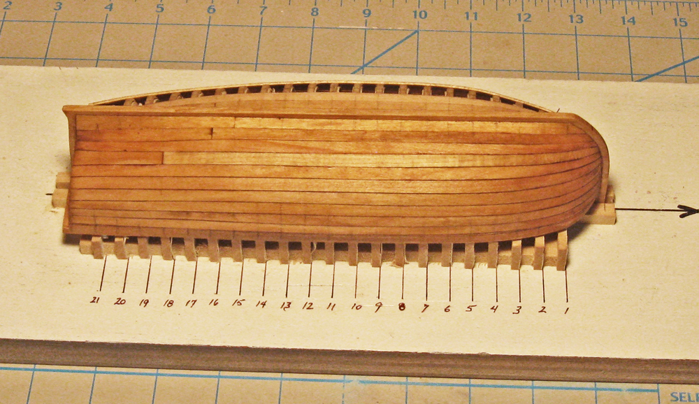
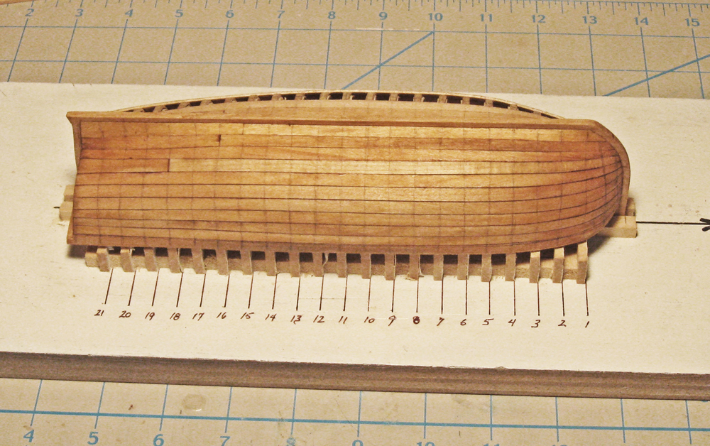
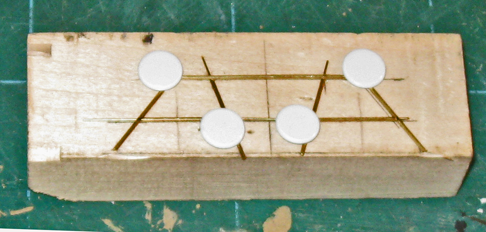
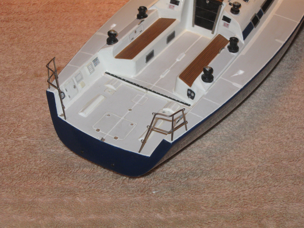
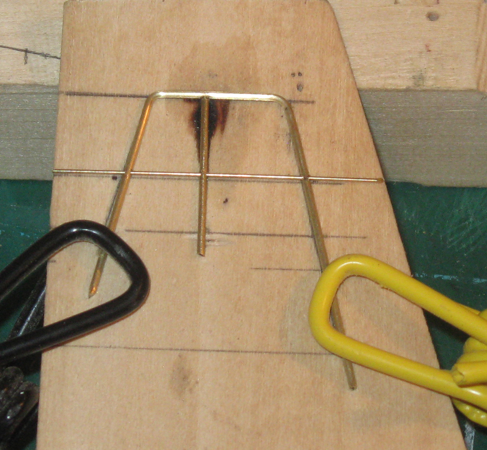
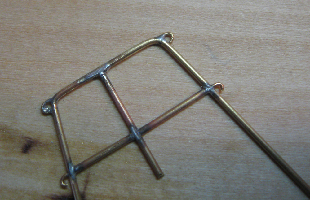
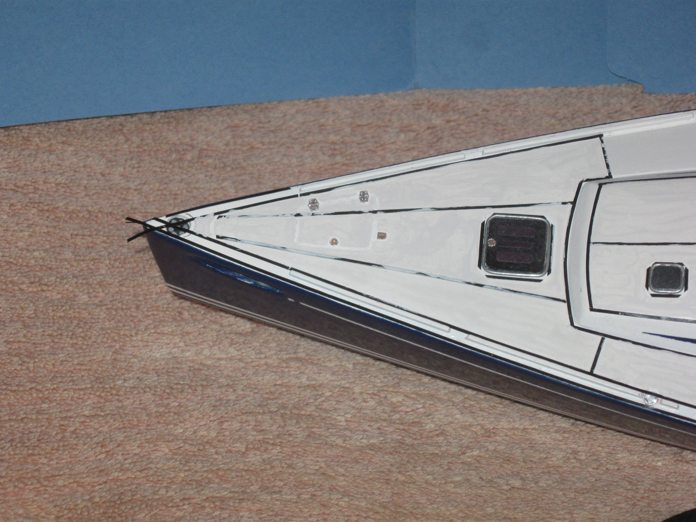
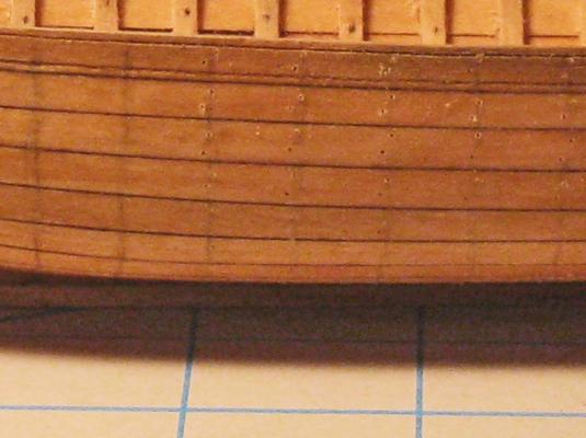
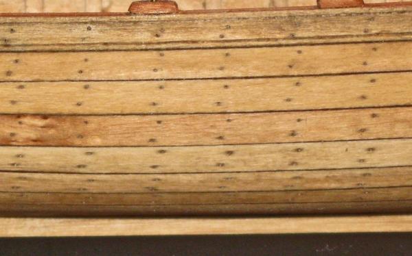
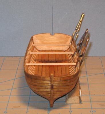
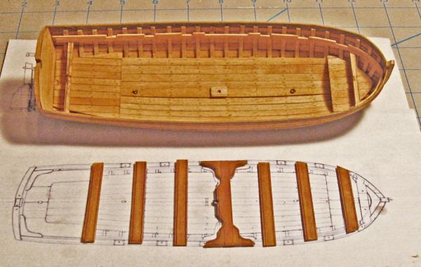
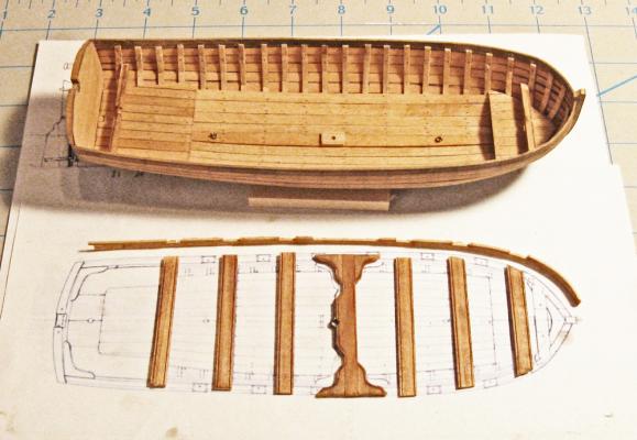
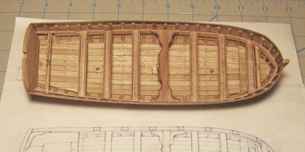
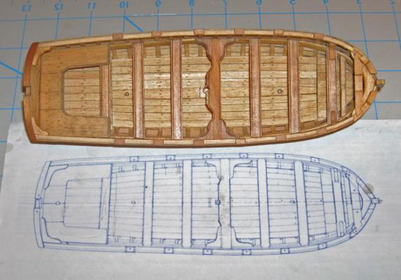
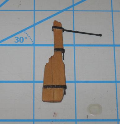
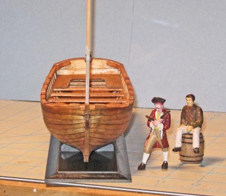
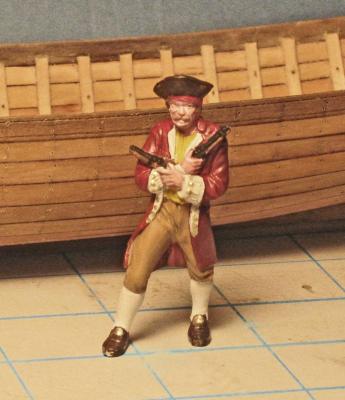
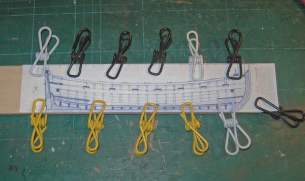
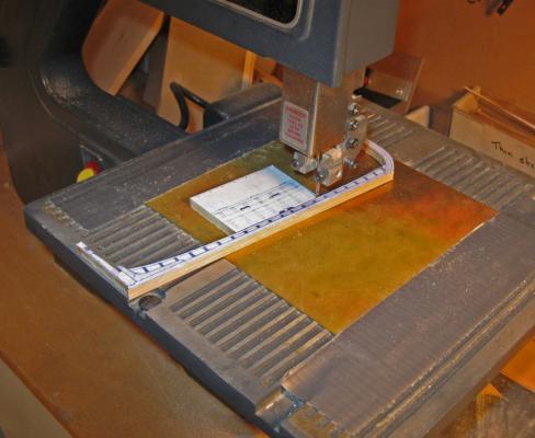
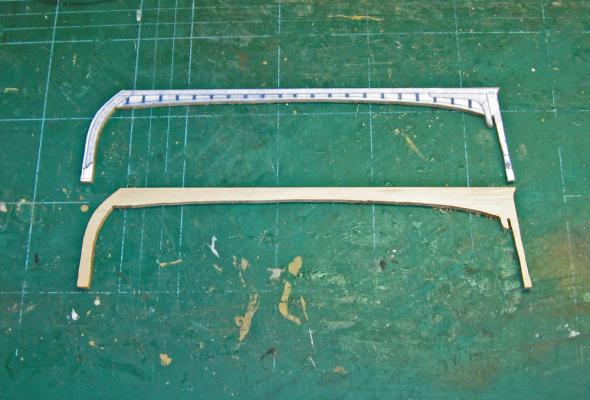
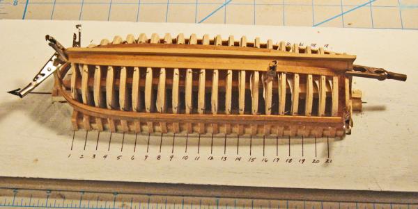
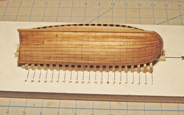
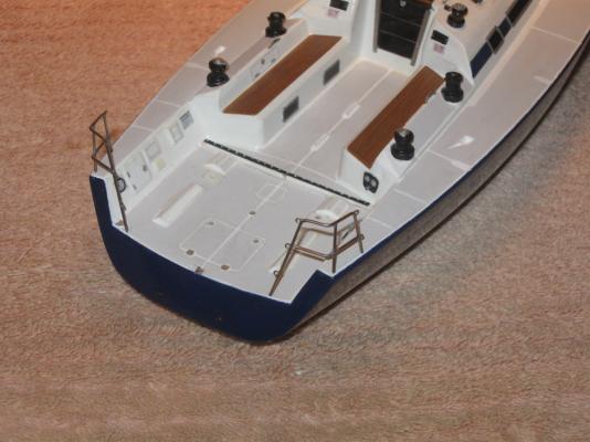
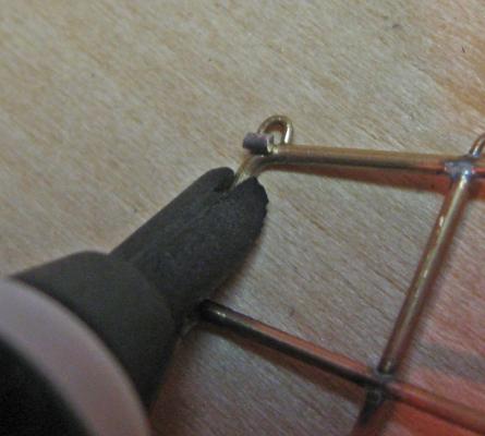
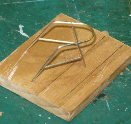
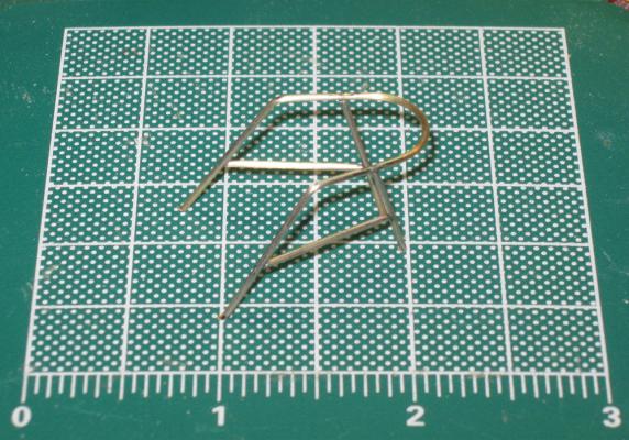
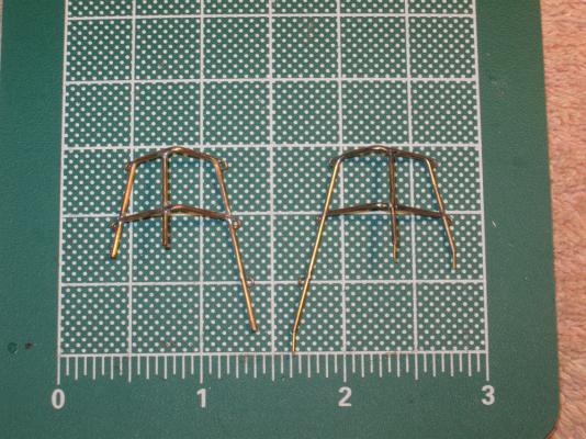
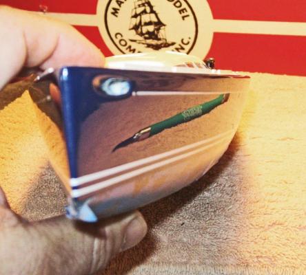
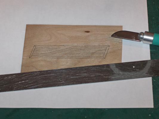
Hi all – Thanks for your comments and suggestions. I plan to incorporate them into the second iteration of the boat which will be built when the hardwood strips arrive from the supplier. When we left the shipyard the hull of the boat had been fully planked with the shutter planks fitted on both sides. The hull had been marked out in pencil for the rib locations in preparation for the nails which would have fastened the planks to the ribs. Here you can see the lines for all of the ribs that sit square to the keel as well as for the two cant ribs, drawn on the port side of the hull. For the fasteners I had to find a way to make them look right without devoting an excessive amount of time to the task. Since there are 11 planks on each side, 25 rib or transom/stem lines that the planks cross, and two fasteners per crossing, the math says that there have to be 1100 fasteners for the exterior of each boat. Add in some more for the interior work and you can see the magnitude of the problem. The original boat probably had the planks nailed to the ribs, with the ends peened over to clinch them. I experimented with a plank/rib mockup and could never get the holes in the planks to come through the ribs in the proper places. Instead, I decided to drill the holes through only the planks and worry about indicating the nails on the inside of the ribs later. I first drilled all the holes. Here you can see how there are two in each plank in an offset pattern. I used a 0.012” drill, which scales up to 1/2”, which would be about right. At first I tried inserting pieces of annealed iron wire into the holes, clipping them short, painting them with glue, then filing the tops flush with the face of the planks. This was incredibly time consuming and fiddly. I then decided to try the technique of leaving the holes empty, sanding the planks to fill the holes with sawdust, then painting on a finish to hold in the sawdust. This looked good and I don’t believe that anyone can tell the difference with this short cut. * * * Aarrrgh, scalawag that ye are! Ye’ll not be taking any modern short cuts with me boats. I be Dread Pirate Peter, and I’ll have yer guts fer garters if ye dinna do a manly and proper piece of work. No, no, it will be OK. Really it will. Here, this is what the nail holes look like after filling and staining. I have had several critical people, including my wife, compare them to the ones with the iron nails in them and no one could tell the difference. In fact, the slightly spread discoloration of the wood grain closely mimics the way old wood stains when a nail rusts into it. * * * Tis all very well and comely, but rest ye not on yer laurels, lest ye rest on yer ****. I be watching ye. . . * * * Soooo, with that out of the way, I turned to fitting out the interior. First the missing ribs were bent and fitted into the interior. These were the two cant ribs at the bow and the aftmost rib at Station 21 that had been left off to make planking easier. The first interior piece to be installed was the tapered central plank of the flooring. It strengthens the keel and is the location for the lifting rings and mast step. To each side the rest of the floor planks were installed. They are not tapered but fit against the tapered center plank due to the curvature of the hull. They are held in place while the glue dries by inexpensive hair clips from the cosmetics section of the drug store. They initially look like the one at the lower left, but are easily bent by hand to the shape in the lower right. This now allows them to reach around the hull to apply pressure at the tips. Next to be installed are the sheets, the planked platforms at the bow and stern. They will appear in later photos, but I did not take pictures as they were being built. Construction is straightforward. Planks were glued to a pair of battens underneath to make a flat sheet larger than needed. A paper pattern is cut to fit the space and the wood sheet is cut to that shape. The edges are bevelled to match the curve of the hull and it is glued in place to the ribs. Now the thwart stringers are installed. I first bent one piece of stripwood to shape and glued it in on the starboard side at the height indicated on the plans. The matching strip was bent and trimmed for the port side and held in place temporarily while I balanced pieces of stripwood across from side to side and set perpendicular to the keel. These are known in woodworking as ‘winding sticks’ although I don’t know why. Looking across their tops you can easily see any variation from side to side and any tipping compared to the centerline and the edge of the sheets. Once I was satisfied with the levels, the port stringer was glued in place. The plans show square section wood pieces running side to side just under the thwart stringers near the bow and stern. They have a short section in the center that has a round cross section. I do not know what they were for, but perhaps the rounded section would have a halyard led around it when the sail was raised, sort of a non-turning sheave. Whatever they are they were shaped, fitted and glued in. The lifting rings and mast step were located and attached to the central floor plank. I also drilled the nail holes for the floors and sheets as I did for the hull planks. My one regret is that I did not do this for the ribs at this point when they were exposed. It turned out to be too crowded later – a detail that will be corrected on the next boats. The thwarts were cut from 1mm thick stock, with the middle one being wider in the center and having added knees. It holds and supports the metalwork that acts as the mast partner. This fitting is made from brass strip which is chemically blackened, then glued and pinned with wire nails to the edge of the thwart. A decorative beading was scribed into the edges of the thwarts, then they were installed on top of the stringers with spacers between them. Unfortunately, once the thwarts were installed it was clear that they were sitting too high in the boat. No rowers could have sat on them and had their feet reach the floor for leverage. Here the flexibility of the Lineco glue came to my rescue. With the tip of a #10 blade I was able to pry up the thwarts from the stringers and then remove the stringers without any damage to the hull or ribs. The stringers were lowered 6 scale inches and reinstalled, followed by the thwarts, which looked much better after the adjustment. I went back to the plans and determined that the problem was there and not in my measuring or building. Just one of those problems that had to be built to be discovered. Fitting out the rest of the interior is self-explanatory. Working up from the thwarts the stern seats were planked up over battens. They sit on top of the thwart stringers and the aftmost thwart. The foremost thwart has a pair of knees set on top. Square section stringers were fitted and glued to the inner sides of the sheer strake so their tops matched, and were strengthened at the bow by a breasthook and at the stern by two transom knees. Thole blocks were set on top of the sheer strakes and stringers and will be drilled for the thole pins to be added later. The locations of several of these had to be adjusted from the plans, which did not have them at a consistent distance from the associated thwart. The only difficult woodworking came at the bow where the curved and carved fairleads on either side of the stem were joined with a double-dovetailed cross-support. With the boat all but complete the rudder was fashioned to match the plans. Two planks were fitted and tapered, then cut to the proper profile. The pintle straps were made from brass strip, pinned through with iron wire and chemically blackened. The tiller is brass bar that was tapered and blackened, with an epoxy bulb at its tip. Top and bottom gudgeons were fashioned from blackened brass strip. The upper one simply slipped into a hole drilled into the aft face of the sternpost, while the lower one had to be bent in several directions before being pinned against the sides of the sternpost. It only remained for the thole pins to be installed and the boat was complete. * * * So ye think ye be quite clever, do ye? Quite the boat builder? I be the judge of that. I also bring me great-great-great grandson Peter who says he has worked with ye before. He be a great galoot of a puppy, but he be useful to judge yer work. He set up this temporary mast and I grant ye that said boat be mightily even side to side. He sits well in the stern and nothing pulls my eye to say that he could not reach and steer the tiller, should he take it into his head to do some work, the lazy lout that he be. It shivers me innards to grudge ye my approval, but i’ faith I canna find much to dislike. But be warned that I will no be put off with such minor success. Ye must do as well or better, or feel me wrath fall upon ye like to the Trump of Doom. Well, there you have it. The second boat will be made from hardwoods now that most of the construction problems have been identified, although I am sure that new ones will appear and demand solutions. Those may be harder to find while looking over my shoulder all the time; Dread Pirate Peter seems to have very high standards, and a very short temper. Till then, be well. Dan


- 241 replies
-
- 23
-
-
- queen annes revenge
- pirate
- (and 2 more)
-
HMS Sussex by mij - Scale 1:48
shipmodel replied to mij's topic in - Build logs for subjects built 1501 - 1750
Very nice work in a larger scale. I'm willing to spend a few years following your journey. Are you fairing the insides of the frames as you go along, or will you wait till the exteriors are faired? Dan . -
Gas spectrometry, a fascinating suggestion and worth much more than two cents. I don't know if the conservators have any plans to get it done, but that's a good question to send them through the website. I would be very interested in what they tell you. As for scale - yes, I believe that it has something to do with the final display space. It's a clumsy scale to work in with 1 inch = 3 feet. It scales down very awkwardly with 1/8" = 4 and a half inches and 1mm = 1.5 inches Dan
-
Thanks for the feedback - AVS in Jerome (sorry, don't know your name) - I am following the research done by those better at that than I, and with better access to primary documents. If you go to the Queen Anne's Revenge website you can access the reports by these researchers as well as graduate dissertations that synthesize and analyze them. From these it is pretty clear that the ship was built in a French (possibly Dutch, but unlikely) shipyard for a private business run by the Montaudoin family. Here is the link to the doctoral dissertation by Mark Wilde-Ramsing. http://wayback.archive-it.org/org-67/20120515002435/http://www.qaronline.org/techSeries/QAR-R-09-02.pdf Druxey - I find spiling by eye to be so much faster and easier than trying to do it mechanically and mathematically. I used to do the whole proportional divider and tick strip thing, only to find that I was fairing the resulting planks by eye anyway. Now I just select my basic plank width at the point of maximum breadth and adjust from there. Actually, this is quite close to how full sized wooden boats are built, even up to 100 foot yachts such as the Coronet, now being restored at the International Yacht Restoration School in Newport, RI (a wonderful detour if you are down that way). You can read about this process in a very funny and captivating book about the Benjamin & Gannon shipyard on Martha's Vineyard called "Wooden Boats" by Michael Ruhlman, who is now a well-known food writer. As for the ribs, I had the same thought, but this is not the light pinnace or Admiral's launch, but a heavy workboat that had to withstand being knocked around and grounded on strange shores. All of the scantlings were probably a bit thick. As you will see, once the floors, thwarts and seats are installed the ribs look well proportioned. At least I think so. Dan
- 241 replies
-
- 2
-
-
- queen annes revenge
- pirate
- (and 2 more)
-
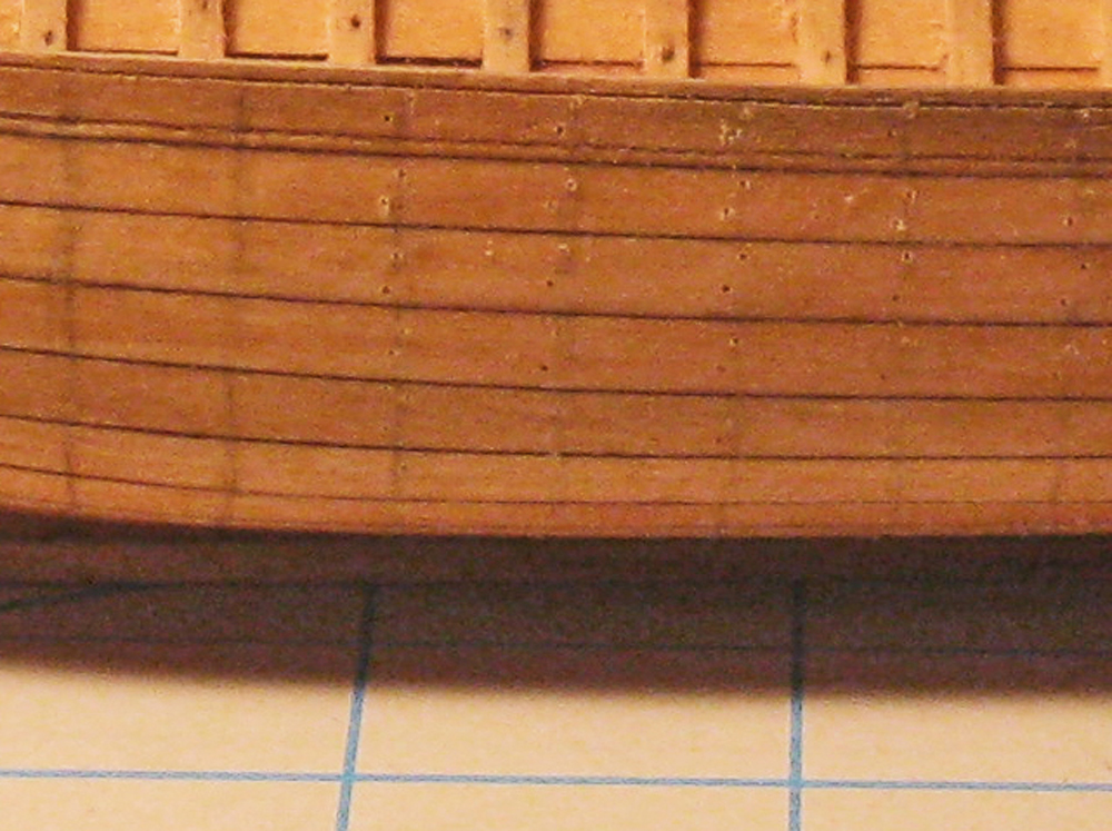
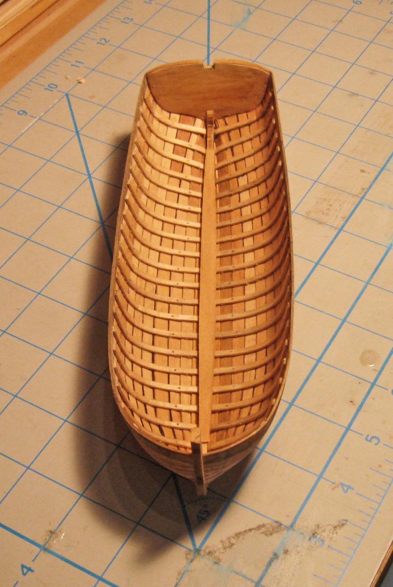
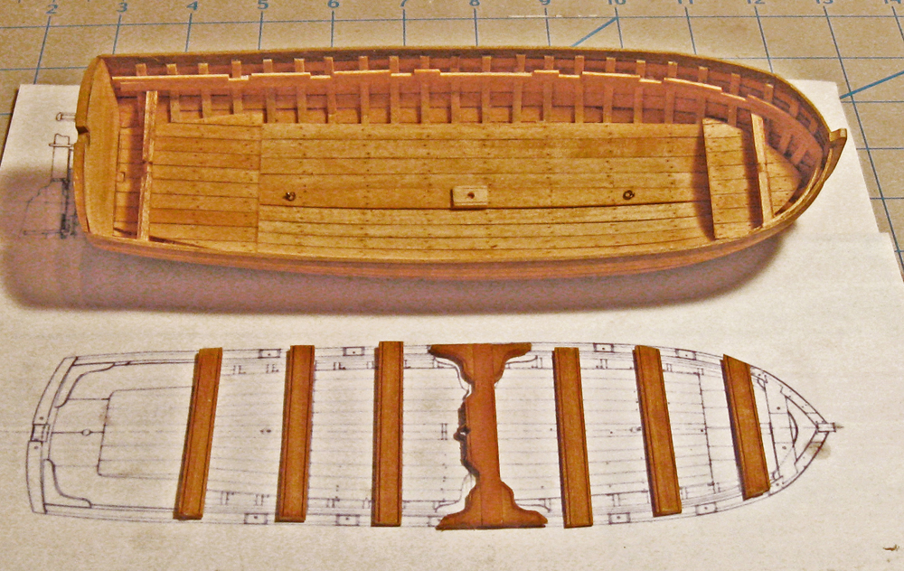
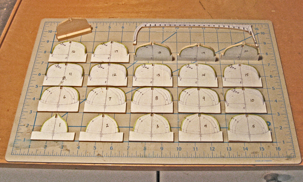
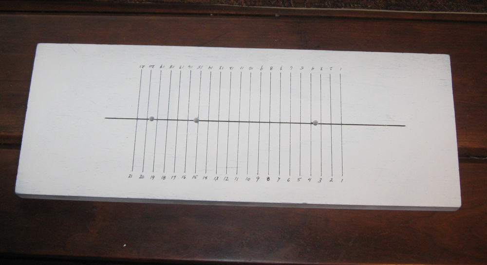
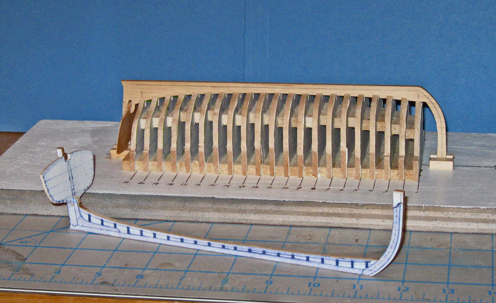
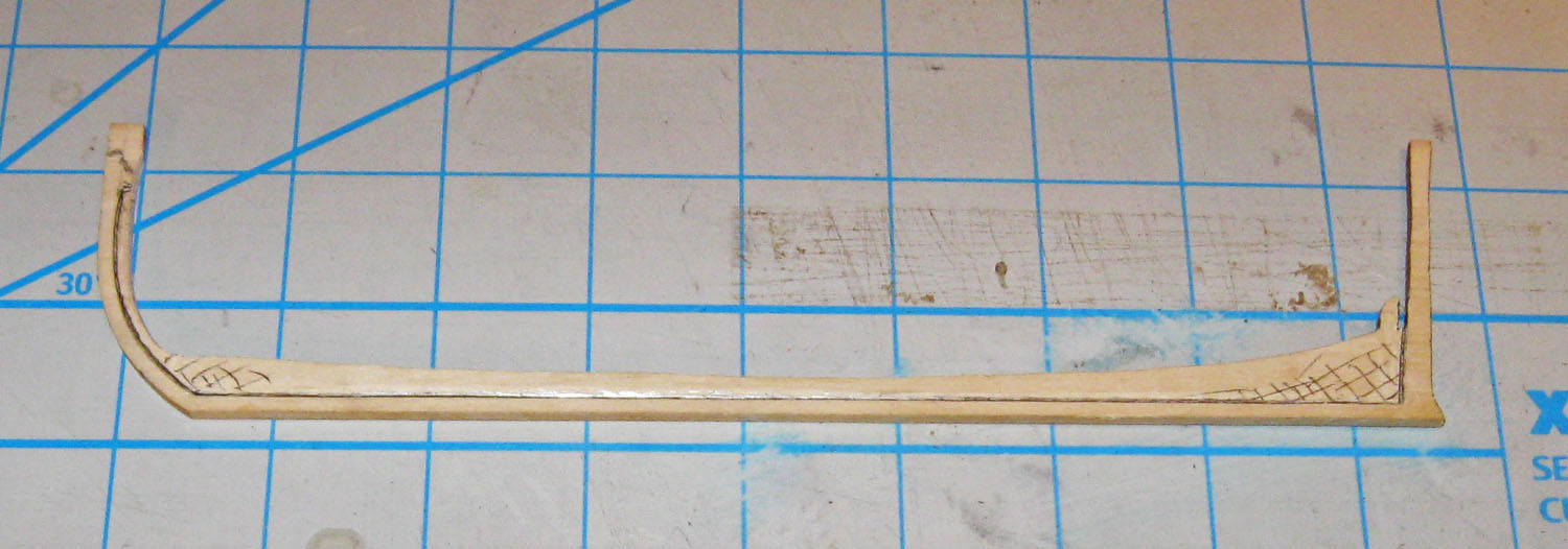
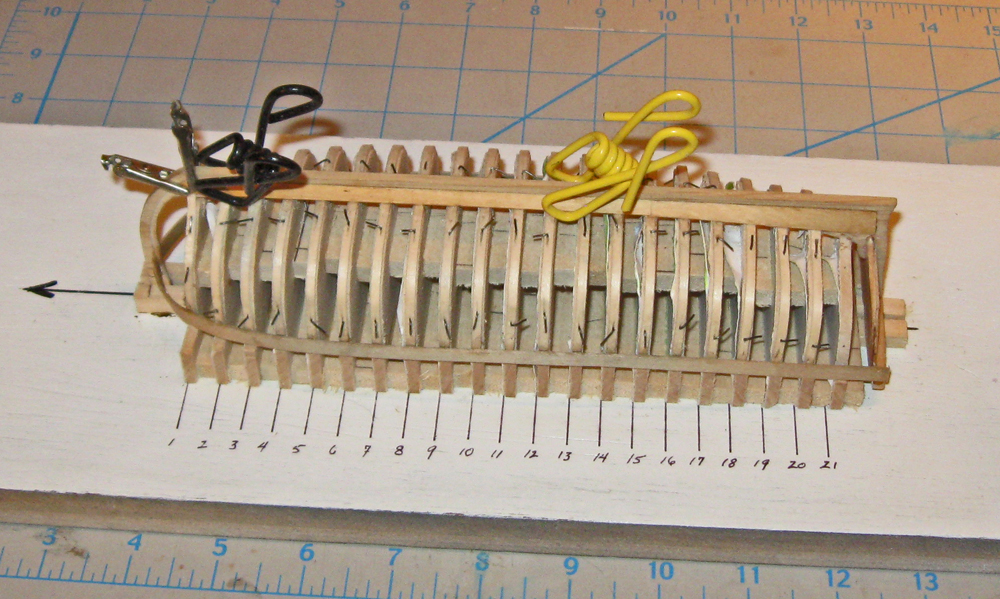
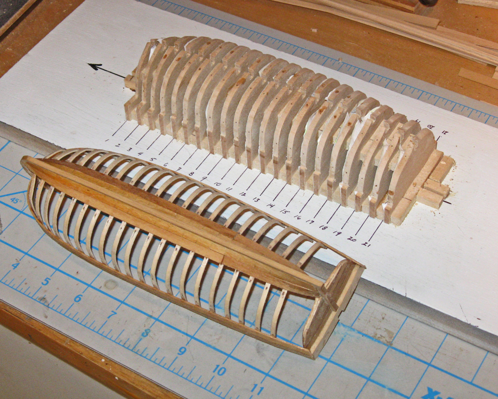
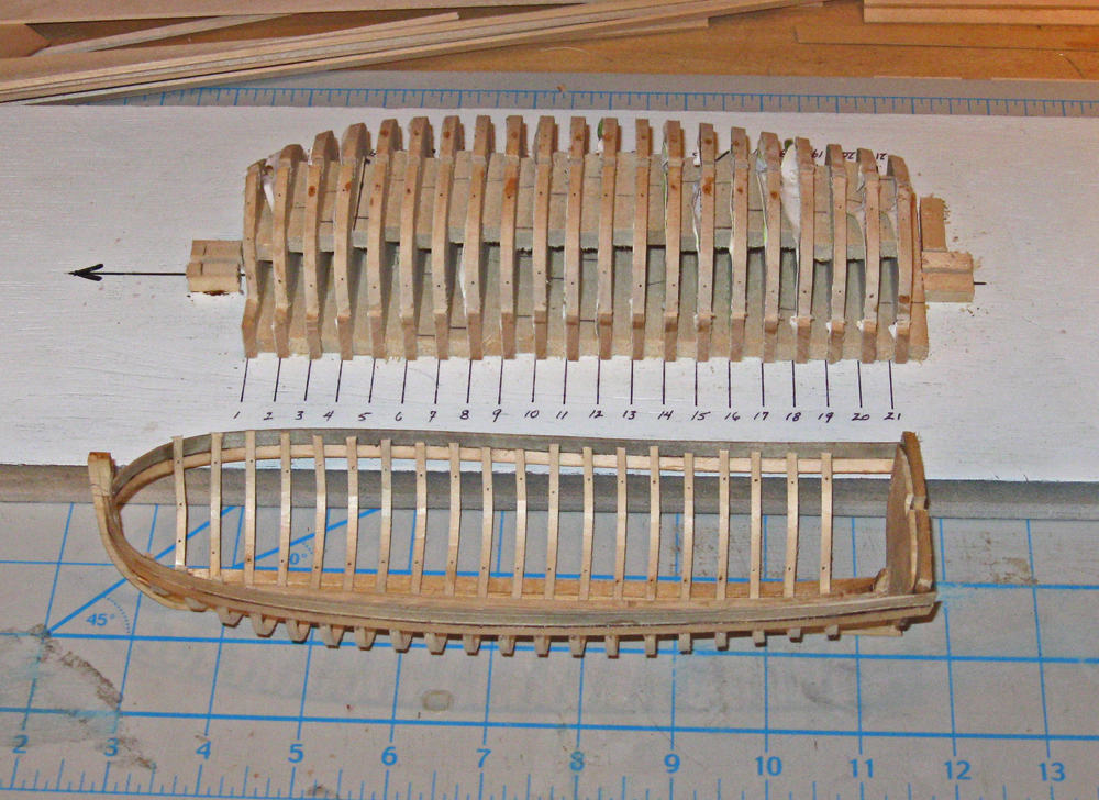
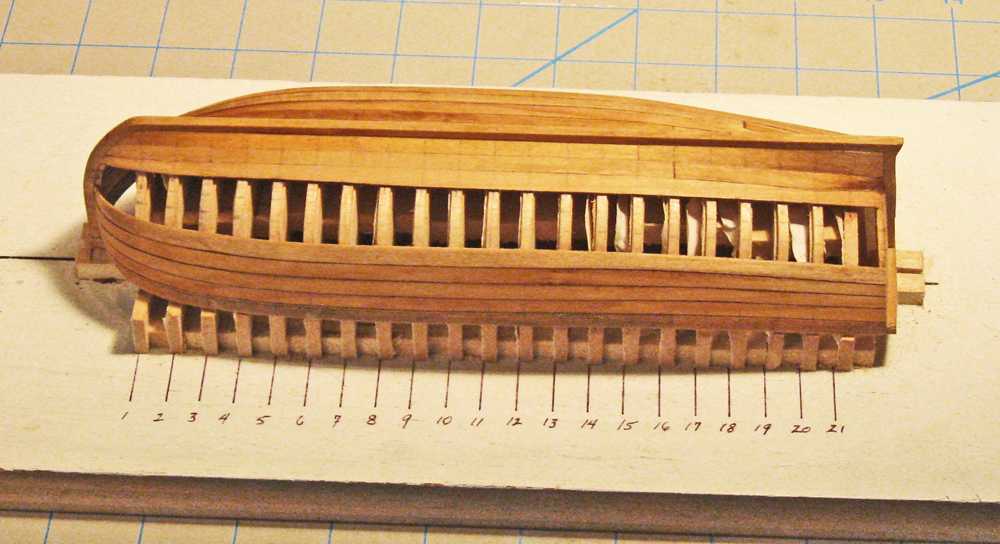
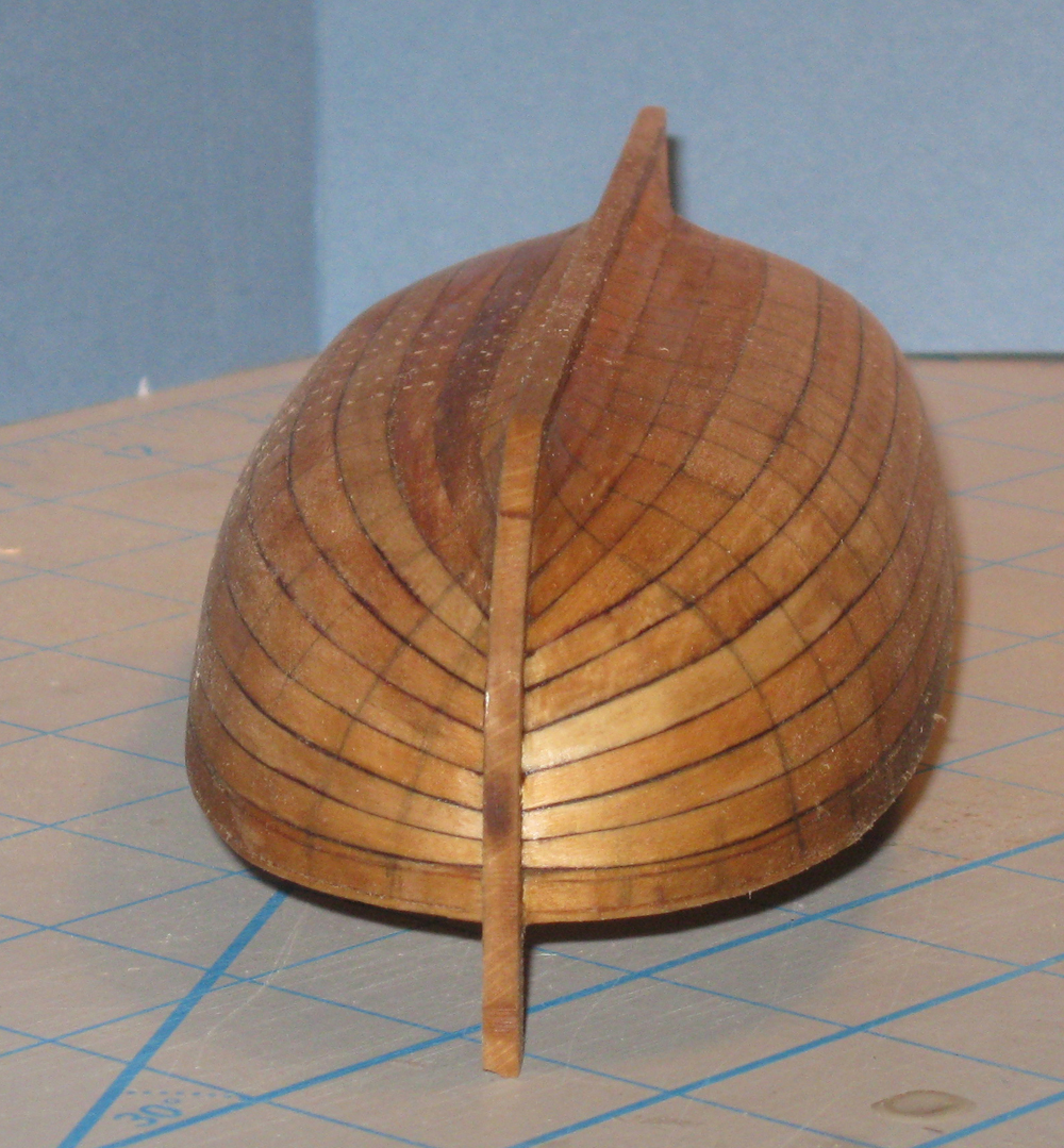
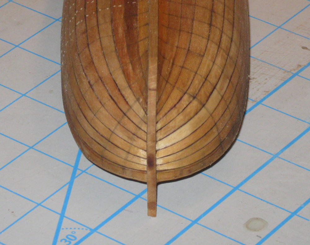
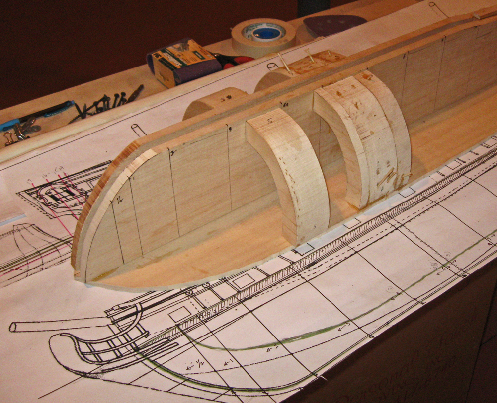
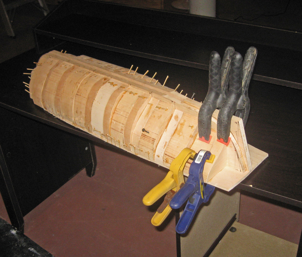
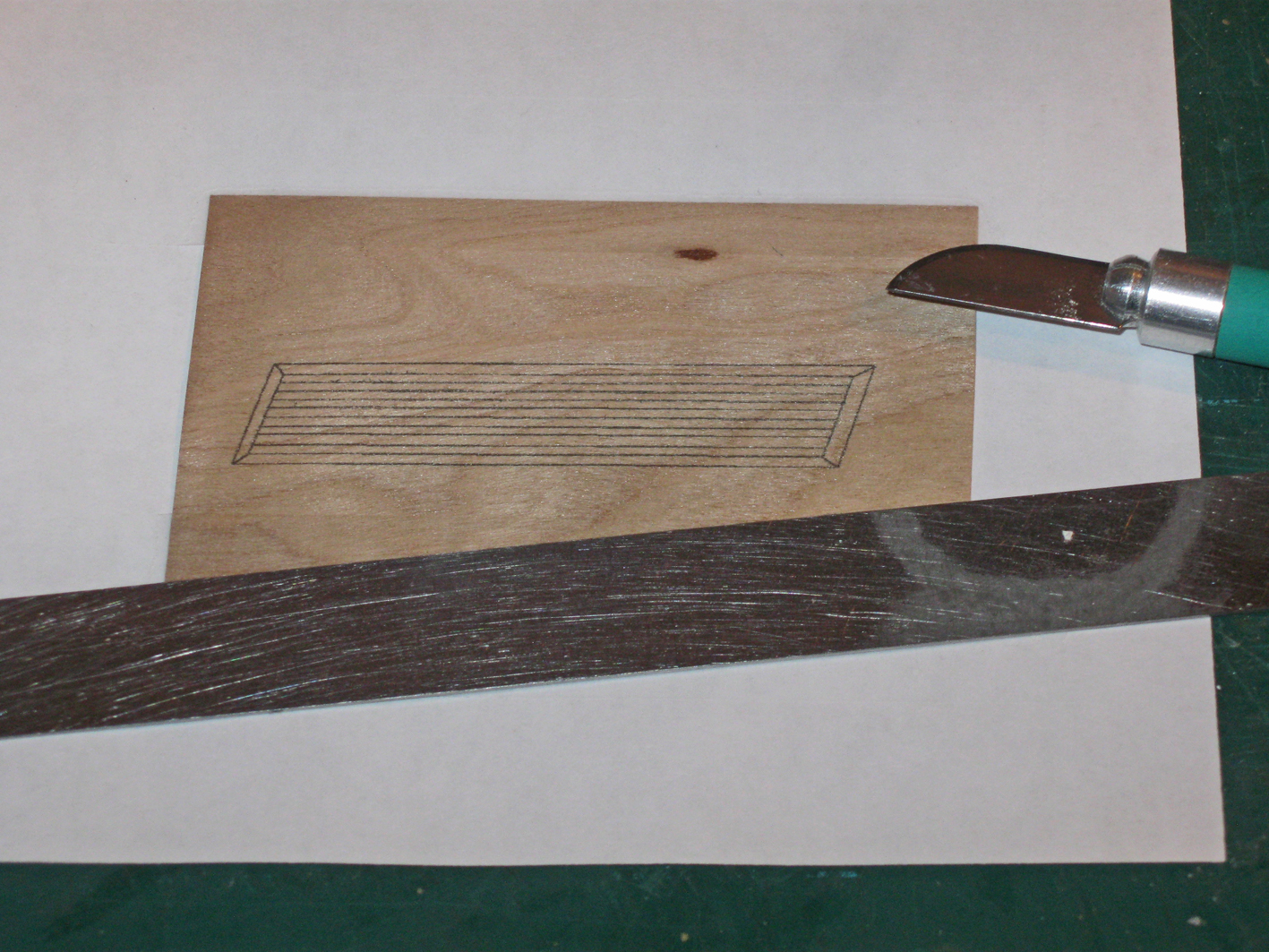
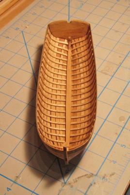
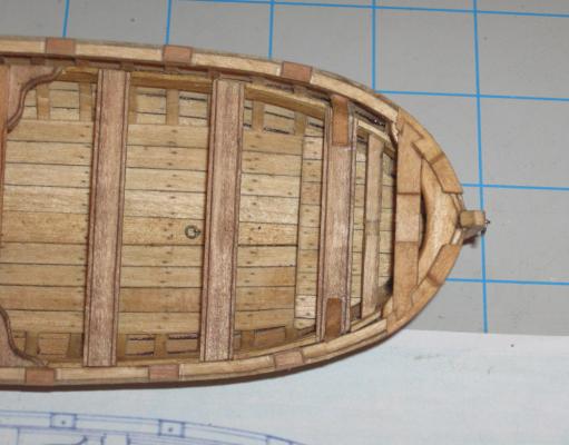
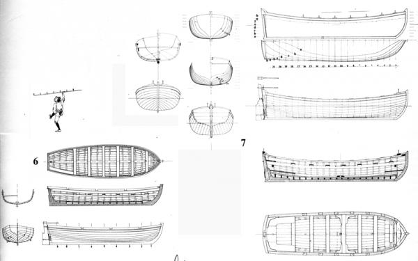
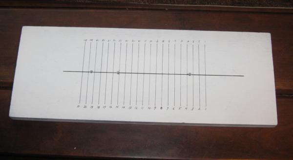
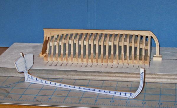
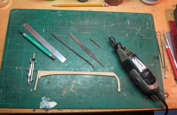
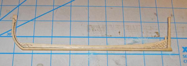
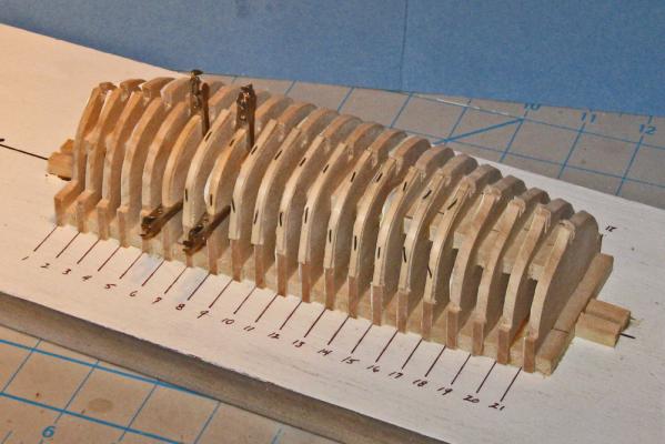
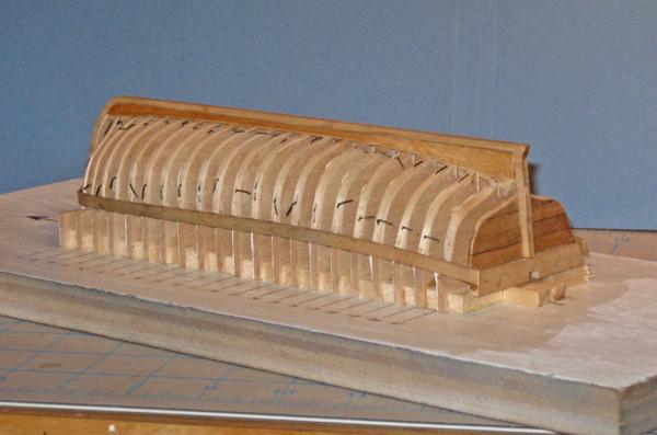
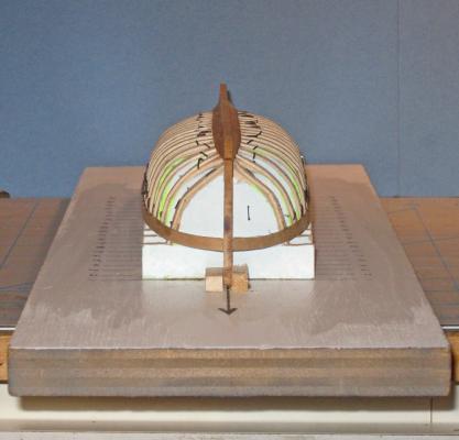
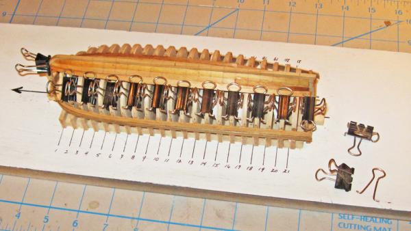
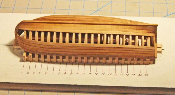
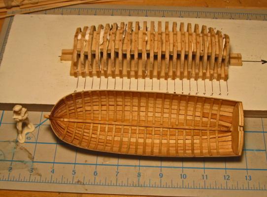
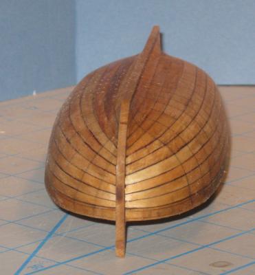
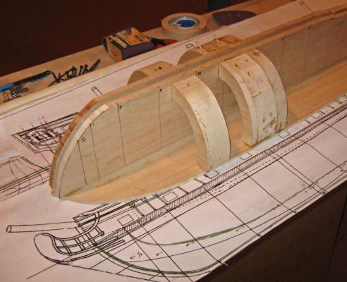
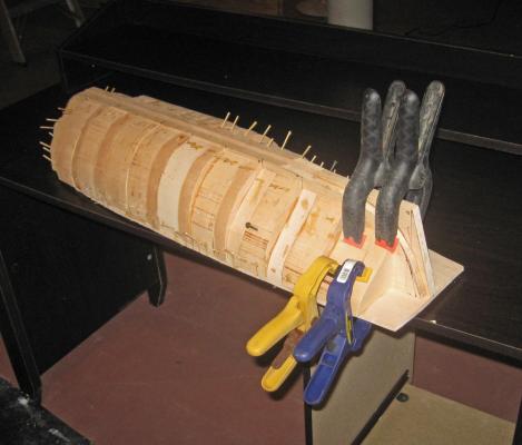
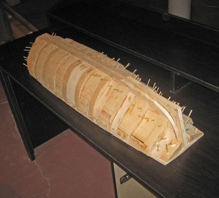
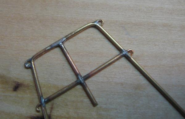
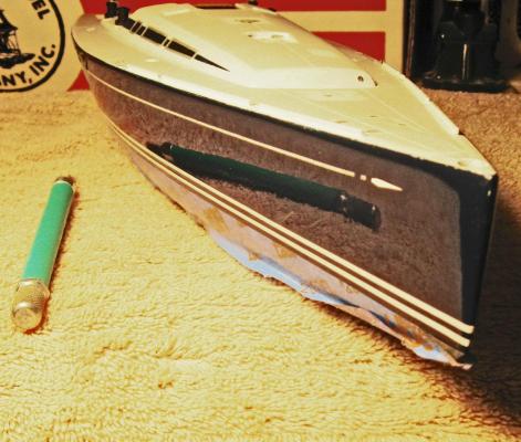
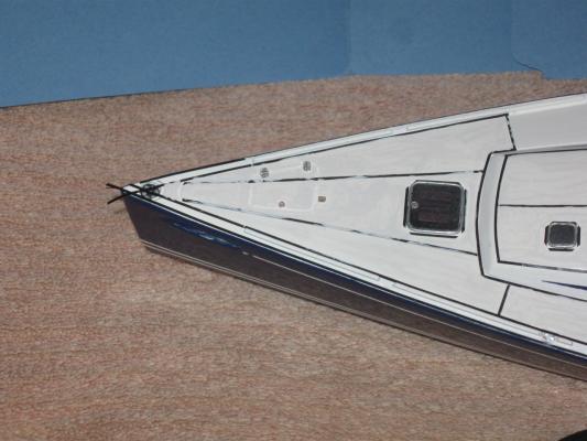
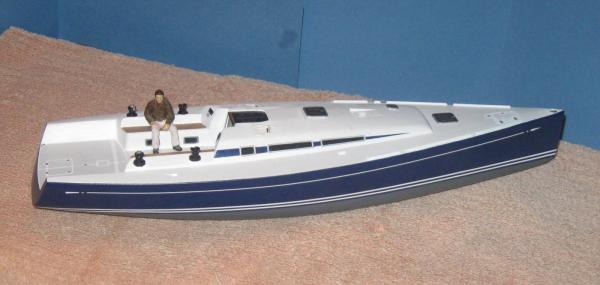
Good day to all - This segment will be a bit of a detour from where I left the hull construction last time. The sheer size of the model means that I have to work on it in the basement of the family’s weekend house near Albany, NY. There is no way that I can fit it into the shipyard in the Brooklyn apartment, which is a converted walk-in closet. I haven’t been up to the house in several weeks, so I am working on smaller pieces here in the city that can be added later. The first of these are the ship’s boats. As always, there are half a dozen good ways to get the job done. Here is mine. The recitation is quite long, so I have broken it up into two parts. The first will cover the shaping and planking of the hull, and the second will finish with the fitting out of the interior. The Mercure drawings that I am working from include plans and schematics for two boats, a large launch (boat 7) and a sleek pinnace (boat 6). Here I will be building the launch. The drawings had been sent to me as .tif files, so it was easy to drop them into Photoshop and start manipulating them. First I used the rule stick in the hand of the little gnome dancing on the page to scale the drawing to the size of the model. I cropped and copied the forward and aft station lines portions of the plans and moved them to a new blank image. Identical square outlines were superimposed around the two drawings to give them the same registration planes and centerlines. Once I was happy that everything was square and aligned correctly they were copied repeatedly to fill a page sized image and printed out several times to get one image for each of the 21 stations shown on the profile and cross section plans. These were cut apart and glued with spray mount to squares of 1/8” wood sheet. The outline at each station was cut out with a notch for the keel and shoulders at the sheer. The three in the upper right are standing up because they have already had spacers glued to their back sides like the one in the upper left. These are used with the building board, which is marked out for the centerline and each numbered station. The station formers are glued to the board and to each other one at a time with a top spacer used to keep them at the proper distance and an engineer’s square to see that they are perfectly vertical. While the glue was drying on the developing stack of formers the two strongbacks (stem-keel-sternpost) were cut out. It is somewhat weaker to do it this way, as you end up with cross-grain on the stem and sternpost, but it is faster, and this boat is something of a test bed for techniques. For the same reason, the wood used is almost exclusively basswood. It is easy to work, glues well, and when stained correctly is almost impossible to distinguish from a close-grained hardwood. The portion of the plans showing the longitudinal cross section was mounted on an 1/8” wood sheet which was then glued to a second sheet, with the glue placed only where the wood would be chucked. The outline of the strongback was cut out on the band saw, leaving a glued central piece to be cut last. This yielded two identical pieces that came apart as soon as the last cut was completed. Here is the completed stack of formers on the building board with one of the strongbacks temporarily set up in the notch for the keel. It goes without saying that once the stack was fully glued it was shaped and faired with sanding rods to get smooth curves from bow to stern. The strongback is held vertically with small blocks at the bow and stern that sandwich the tops at the centerline. Two transom pieces were taken from the plans, laid out and cut as before, and each was test fit into the notch cut for it at the base of the sternpost. The location of the forward edge of the plank rabbet was determined and marked out on the strongback, then the small extensions that had been left above the stem and sternpost were trimmed until it snuggled down into the keel notch at the proper level. The strongback was removed and the rabbet was carved along the line with rotary bitts, then finished with files and rifflers. The transom was planked on the outside and glued in place against the sternpost. Now I fit the ribs to the station formers. It was a happy fact that Budriot drew the boat with a rib at each station line and a station line at each rib. To make room for them I had cut out the station formers a little inside the line, and the sanding and fairing had further reduced the breadth of the stack. The ribs were fairly thin in any case, made from wood strips milled to 1mm x 2mm (about 1.5” x 3” in scale”). These were soaked in water to soften, then bent around each former and wired in place. No glue was used. All of the ribs were wired in place except the aftmost one at Station 21. Leaving it off gave me a little more flexibility in fairing the planks to the transom. The strongback was replaced in the keel notch of the formers and the initial two planks were shaped. The first was the sheer strake. From the plans it measured out to exactly ¼” in width and was left full width its entire length. A strip of basswood that width and 1/16” thick was soaked for a few minutes, then shaped first at the bow, where the tip was cut and angled to fit into the rabbet. The forward few inches were steam bent using an Amati plank bender (the one that looks like a soldering iron with a nautiloid shaped head). It is 25 years old and still works a treat. Using the shoulders cut into the formers at the sheer the plank was edge bent to match the curve before being clamped and glued to each rib and the transom. The garboard strake against the keel was similarly fitted and glued. However, when I tried to impose the required twists into a basswood plank it repeatedly splintered. I therefore used pau marfim, a California hardwood. It is also ¼” wide for most of its length but flares to about twice that at the sternpost. To accommodate this, a tapered plank was pieced in from Station 15 to the sternpost. When I was happy with the look of the shape it was clamped and glued to the ribs. Here is what they looked like with most of the clamps removed. A word here about stains and glues. Before any piece was installed it was given a staining with a mixture of ½ clear Minwax wood stain which they call Natural, ¼ Early American and ¼ Cherry. I find this combination the best to reduce any splotchiness in the basswood and makes basswood resemble boxwood or one of the lighter cherry varieties, a look that I like a lot. However, the stain is a bit oily, so the wood has to be well wiped and has to dry for a while before normal PVA glues will hold well. As for glue, I use a pH neutral white glue made by Lineco which I used to get from an art conservation supply house. It sets up fast and holds well, yet is still flexible for an extended time, which will come in handy later. Now I get it through Amazon where it is competitively priced with carpenters’ wood glues. This process was repeated for the second sheer plank and the first broad strake against the garboard, but these had to be tapered to fit at the bow. I knew from test fittings with strips of paper that there was almost exactly half the space between the garboard and sheer strake at the bow than there was between these planks amidships. Therefore the next two planks were tapered for their forward three inches to that dimension. Holding the plank to the formers and letting it find its own best fit, it was evident that the tapering on the second sheer strake should come off the edge that mated with the sheer strake, while the broad strake should taper on the garboard side. After the bulk of the wood was removed the edge was sanded to a fair curve. This spiling was all done by eye, with the curve examined from every angle and refined as needed on this and every successive plank. Once acceptably shaped the planks were stained, then caulking was indicated by coloring the uncut edge of the plank with an indelible black marker. The planks were bent to final shape, fitted, glued and clamped in place. With two strakes at the keel and two at the sheer, the cage of ribs had a good deal of strength and rigidity. Now all of the wires were pulled out and the developing hull was removed from the formers. I must have done a clean job with the glue because I didn’t have to pry it loose at any point. Subsequent strakes were processed in a similar way. For clamps I used bulldog clips that had a handle piece from a second clip fitted into the top of the clip. A modified clip was used on every other former to hold the plank to the ribs as the glue dried. Here is what the hull looked like with 8 of the 11 strakes in place. At this point the remaining space was divided into thirds as you can see from the pencil marks on the ribs. This would be filled with two standard width planks and one custom fit ‘shutter plank’ that closed in the hull. Here is one completed side. The shutter plank location was selected to lie just under the curve of the chine of the hull, making it less visible than any other spot. It is the fourth from the keel. It is slightly wider than the other planks and flares at the stern to fill the larger space. While it was on the formers the location of each rib was penciled onto the planks in preparation for the ‘nails’ holding the planks to the ribs. Once the other side was closed up the hull was removed from the formers. I think the method worked quite well and resulted in a hull that is strong, symmetric, and gives a convincing appearance of an actual boat structure. The white plastic figure in the corner is useful to judge scale appearance and will appear again. Spiling the planking by eye in this way is an acquired skill, but not difficult if each plank is critically examined and adjusted as needed. The final hull has a nice run of planking that tapers smoothly to the stem and matches, port to starboard, and even has the little variations in width that a real boat does. In the next installment I use the penciled lines to drill the nail holes for the more than 1100 fasteners used for the hull planks. Then I fit out the interior and finish the boat. As always, critical review by the eyes of my peers is requested. This is even more so in this case since the boat is the first generation attempt and, despite the work and time invested, may not make the final cut. Looking forward to hearing from all. Dan


- 241 replies
-
- 19
-
-
- queen annes revenge
- pirate
- (and 2 more)
-
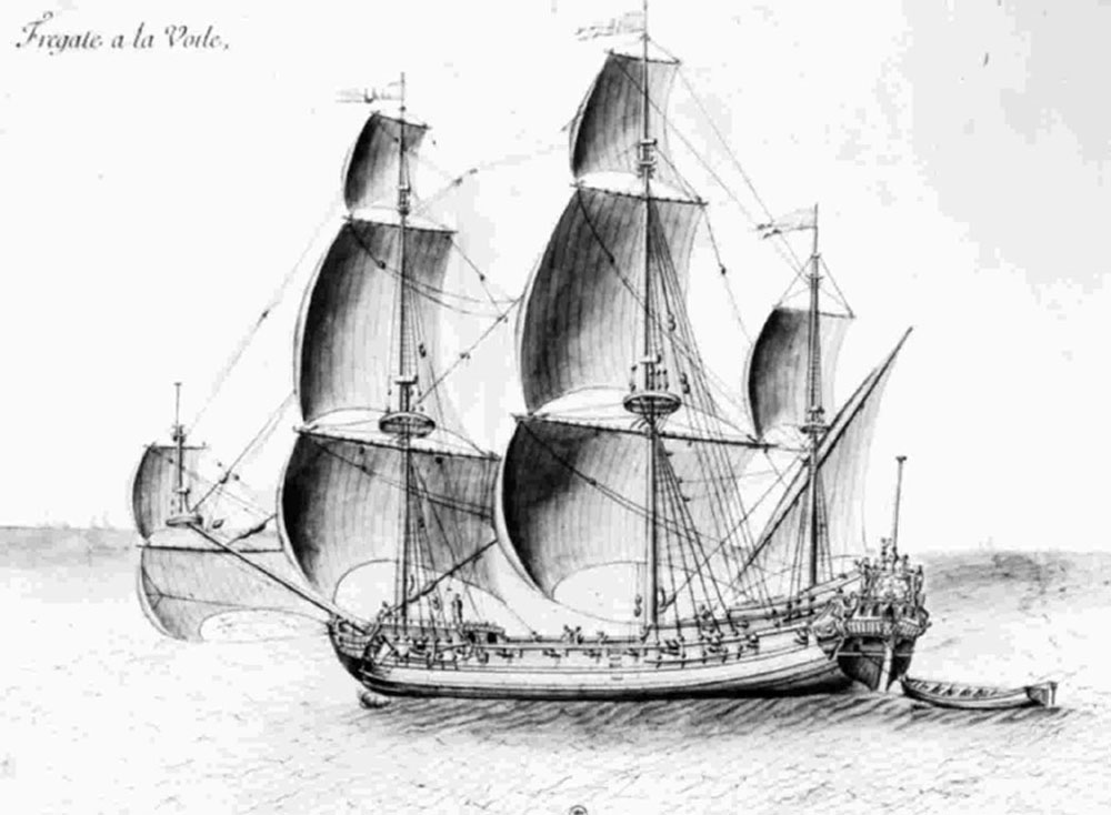
Hi all - Yes, an interesting project that is open to some speculation. Although there is no definitive information on the ship's appearance, we can reason backward from what is known. A researcher on the project has combed through the French archives and in his 159 page report he convincingly demonstrates that she was built as La Concorde for a private commercial firm, rather than for the French navy. She is described as being one of the light frigates of 250 to 300 tons, which fits well with other such ships being built for the navy, so her design was probably quite similar. Budriot, in his major work, "The History of the French Frigate, 1650-1850" has a short chapter on these light frigates with illustrations of several of the naval frigates as well as lines drawings and artistic illustrations such as the one that I included. There is even a lengthy written description of a "Light frigate armed with 20 6-pounders" which is exactly what the Queen Anne's Revenge was. I am still working through the dense prose to glean bits of useful information. However, she was not built for the navy, but for a private firm. As such, she would not have had the elaborate carvings, paint and decorations that a national warship would have carried and which Budriot puts on Le Mercure.. Even if there were originally some touches of color, by the time she finished a privateering cruise and two slaving trips some seven years later I do not believe that any would have remained. We are on surer ground with the rig. Masts and spars were pretty well standardized by 1710 for the size of the ship. Budriot provides a detailed drawing of all of the sticks and fittings in the Mercure drawings, which will be checked against Lees, Petrejus and other writers. But that is for later - much later. Till then, be well. Dan
- 241 replies
-
- 2
-
-
- queen annes revenge
- pirate
- (and 2 more)
-
Hi all - If you want to follow my next build, I have started a log for the Queen Anne's Revenge in the scratch-built forum. I do not have the direct link, but it should be easy to find. Looking forward to all of your comments and suggestions for improvements. Dan
-
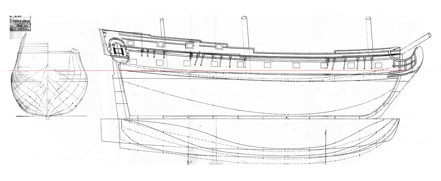
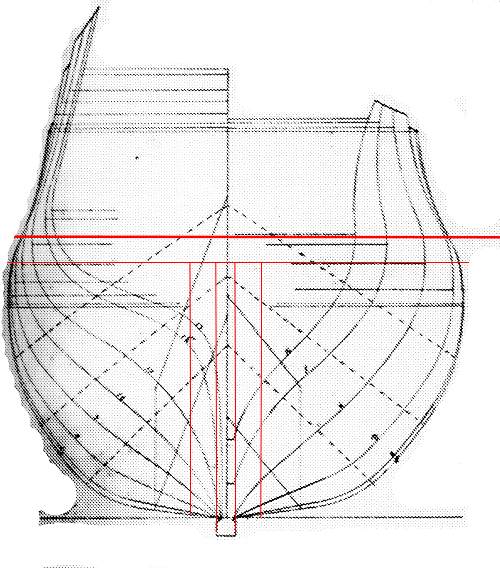
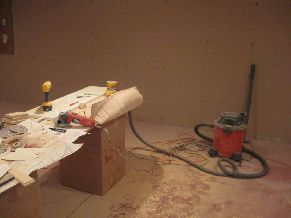
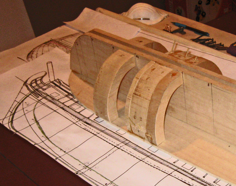
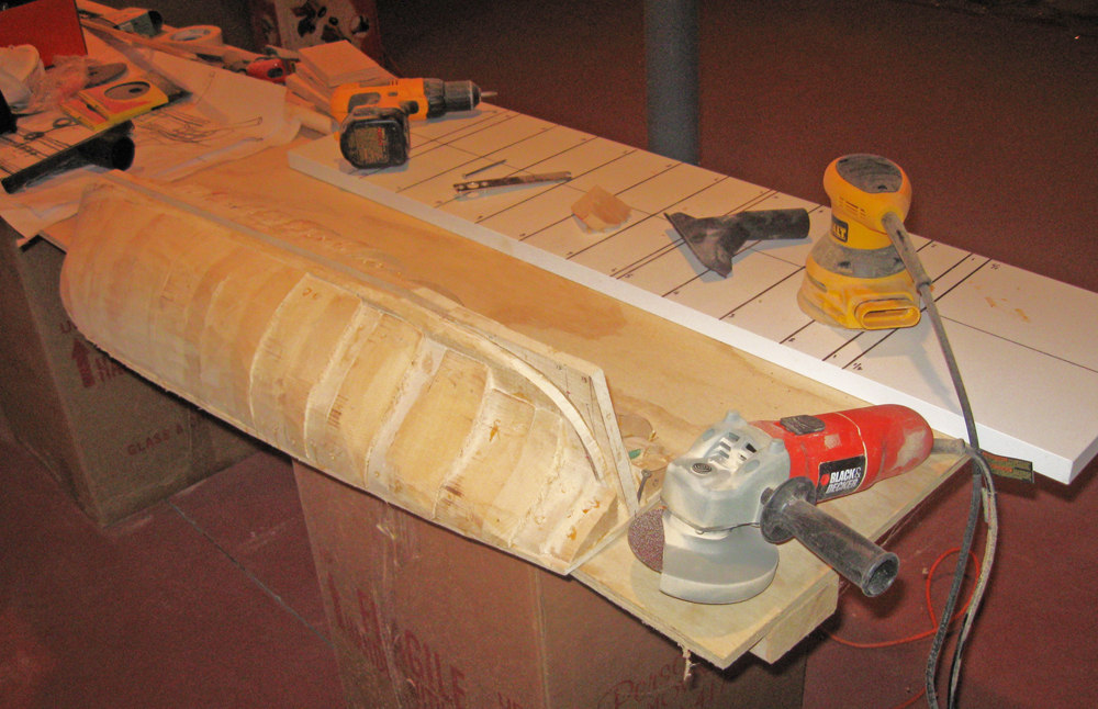
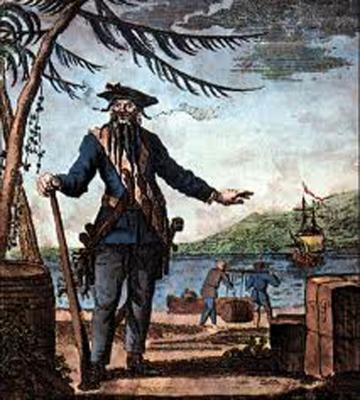
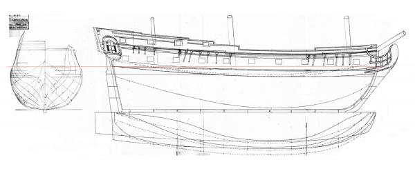
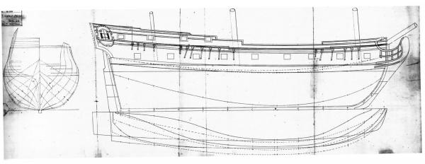
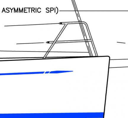
Hello to all - Those of you who followed my building of the Swan 42 racing yacht may experience some temporal whiplash as the Wayback Machine moves the shipyard some 300 years into the past. Even though the scale will be about the same, the materials, methods, and style will have little or nothing in common with the last project. We leave the clean lines and millimeter accuracy of a rich man's toy for the rough outlines and incomplete draughts of a pre-Colonial pirate ship. Queen Anne's Revenge was the flagship of the notorious pirate Edward Thatch (incorrectly called Teach), known as Blackbeard. In barely more than a year and a half, from the summer of 1717 to November 22, 1818, he and two other pirate leaders put together a large fleet that took numerous merchant ships, looting them and holding any worthwhile captives for ransom while taking any willing sailors into his piratical crew. He was hardly the most notorious or bloodthirsty pirate, but he captured the popular imagination with his large fierce black beard and his habit of placing lit rope matches for his weapons into his hair during a battle. The origins of the ship herself are not definitively known. It is thought that she was built in about 1710 as a small frigate of about 300 tons known as La Concorde, with her first cruise as a French privateer during Queen Anne's War in 1711. When the war ended in 1713 with the Treaty of Utrecht her owners sent her into the slave trade. She made two profitable cruises between 1713 and 1717, taking slaves from West Africa to the French colonies in the Carribean and capturing prizes on the return leg back to France. On November 28, 1717, during her third slaving cruise, she fell afoul of Blackbeard with two armed sloops. Her crew was sick and many of the cannon had been removed to make more room for slaves so she was captured easily. Below is a drawing of a similar light frigate from the early 1700s. After renaming her Queen Anne's Revenge and adding significantly more cannon, she became Blackbeard's flagship and was used to capture numerous ships and even to blockade the port of Charleston for a week. Turning north from there in company with several smaller pirate ships on June 10, 1718 they tried to enter a shallow anchorage known as Topsail Inlet (or Old Topsail Inlet), now called Beaufort Inlet in North Carolina. Although several other ships entered safely, the larger Queen Anne's Revenge grounded on the sand bar at the entrance, as did another ship that came to her aid. After removing the valuables she was abandoned and left to the cruel mercies of the sea. Blackbeard himself lasted barely another six months until his death in November of 1718 during a battle with the Royal Navy. The ship was rediscovered in 1996 and is now being excavated underwater in project managed by the North Carolina Department of Cultural Affairs and the North Carolina Maritime Museum, part of East Carolina University. Numerous artifacts, including several cannon, coins, navigational equipment, and hundreds of everyday items have been recovered and are being conserved. You can see photographs of the artifacts, view interactive maps of the ship's history and the wreck site, and read the archaeologists' and researchers' detailed reports if you go to the Queen Anne's Revenge website at http://www.qaronline.org/Home.aspx It is a little gem of a site and well worth looking into. I have been asked to build two display models of the QAR for the Maritime Museum. They will be at the large scale of 1:36, yielding a model of some 48" LOA from the tip of the jib boom to the ensign staff at the stern. It will rise some 44" from the keel to the main truck with a main yard of some 22" with stunsail booms rigged but not extended. The hull is to be solid below the gun deck but open and fully detailed above. She is to have a full suit of sails with all sail handling lines, although several will be furled so the deck can be more easily viewed. There are no plans or illustrations of the ship, so her apearance is a bit conjectural. As a basis for the model I have been given two sets of plans. The first is a simple, one-page rendering of the lines and profile of a similar small French frigate which was captured by HMS Advice and which is known therefore as Advice Prize. I am also working from a set of drawings done by Jean Budriot of yet another light French frigate of the period known as Le Mercure. He has written a monograph that is illustrated with numerous detailed drawings of all of the bits and pieces of the ship including several profiles, cross-sections and longitudinal sections, and sail and rigging plans. However, as is his custom, there is no station lines plan from which to derive the hull shape. These two sets of plans have to be reconciled, not only with each other, but with the known historic facts. For example, it was reported in contemporary accounts and court-martial testimony that the Queen Anne's Revenge had 20 large cannon on board when she went down. Le Mercure is pierced for 10 guns on each side, but the Advice Prize has only 9. The Mercure drawings have the channels for the fore and main shrouds set below the gunports, while the Advice Prize has them above. Le Mercure is shown with a square, open beakhead bulkhead, while the plans for the Advice Prize shows a closed in forecastle. At the stern Le Mercure has a large quarter gallery, rather than the small quarter badge of the Advice Prize. But that quarter badge is set very high, with an indication that the Advice Prize had a poop deck above the quarterdeck. These and many other details, large and small, will have to be reconciled as construction continues. To begin with, a tenth gunport was added to the Advice Prize and their spacing was adjusted accordingly. The quarter badge was lowered and it is this resulting profile that will be used to build the models. On this plan you can see a horizontal red line. This is my line of demarcation between the solid hull below and the open gundeck above. It is set at the level of the gundeck for the forward four ports. A tapered piece will be added at the rear half of the ship to account for the sheer rise of the gundeck towards the stern. But this line is also used as my registration plane for setting up the templates for the hull shape at the various stations shown on the plans. As I was working out the hull construction the first of what will surely be many problems arose. In the scale that is required, the maximum breadth of the model works out to just over 9 inches and the station lines work out to, mostly, 3 inches separation. To work from the centerline I would need wood of at least 4.5 inches wide and 3 inches thick. However, wood of that size is not easily or inexpensively acquired. Instead, I found basswood planks 4 inches wide and up to 2 inches thick. I decided therefore to piece together the hull. As you can see in the wood blocking plan below, I started with a vertical central piece 3/8" thick to match the width of the keel. This was sandwiched on each side by a vertical lift 1/2 inch thick, then by the side pieces whch would be cut to the profiles of the appropriate station lines from the plans. As usual with vertical station line lifts, they were cut to the profile of the appropriate station line. For each three inch station segment a two inch lift and a one inch lift were used. I also decided that the hull should be partially hollow, not only to reduce weight, but to give the stresses somewhere to go other than outward when the wood swelled with changing humidity. My solution was to take each lift and cut out the center, leaving a crescent of wood about 1 inch thick. Construction began with the gunport deck piece cut to shape and the three vertical central pieces glued to it using carpenters' squares for alignment. Then the station line lift crescents were glued in place and secured with dowels. Here you can see the first three segments glued and pinned, with the fourth made ready for installation. This was continued from the center out to the bow and stern, with the final lifts left solid and clamped to the growing hull block. The completed hull block was left to dry for a week before the bamboo dowels were trimmed off. Now the carving and shaping had to begin to reduce the stepped shape of the lifts. The model is so large that the usual woodworking tools were inadequate in any reasonable time frame. I therefore purchased an angle grinder and set it up with coarse 50 grit sanding discs. This was followed by a random orbit sander, also with coarse grit paper. As you can imagine, this makes a hellish racket and leaves a hellish mess, Eye, ear and respiration protection are a must, and if you are not going to do all of it outside, you need three other things - an empty room in the basement; a big shop vacuum; and most importantly, an understanding wife. I am glad to say that I have the first two and am blessed with the third. In this photo you can see how far the shaping has progressed. From here there still has to be a lot of hand work that is checked and rechecked as usual with station line templates. The next segment will take us through that process. Be well Dan


- 241 replies
-
- 16
-
-
- queen annes revenge
- pirate
- (and 2 more)
-
Thank you all for your compliments. Peter and I have been very gratified by the responses, both from you and from the owners. In fact, I received two inquiries about models for individual owners. With 55 boat owners out there, this could become a cottage industry for me in my dotage - as if I am not there already . . . :-)) Be well Dan
-
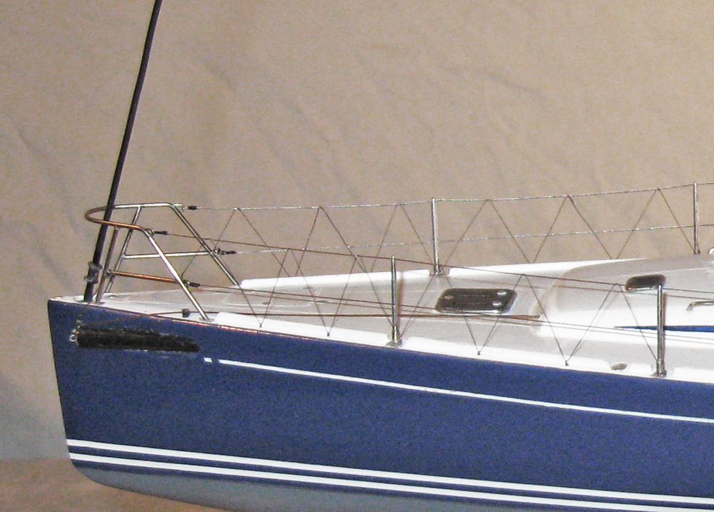
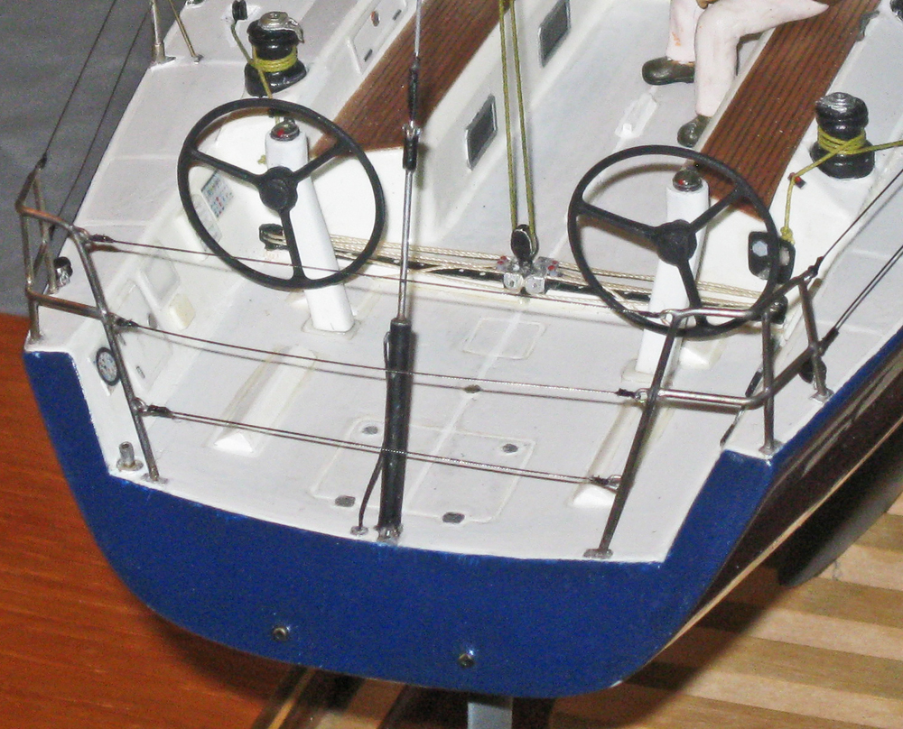
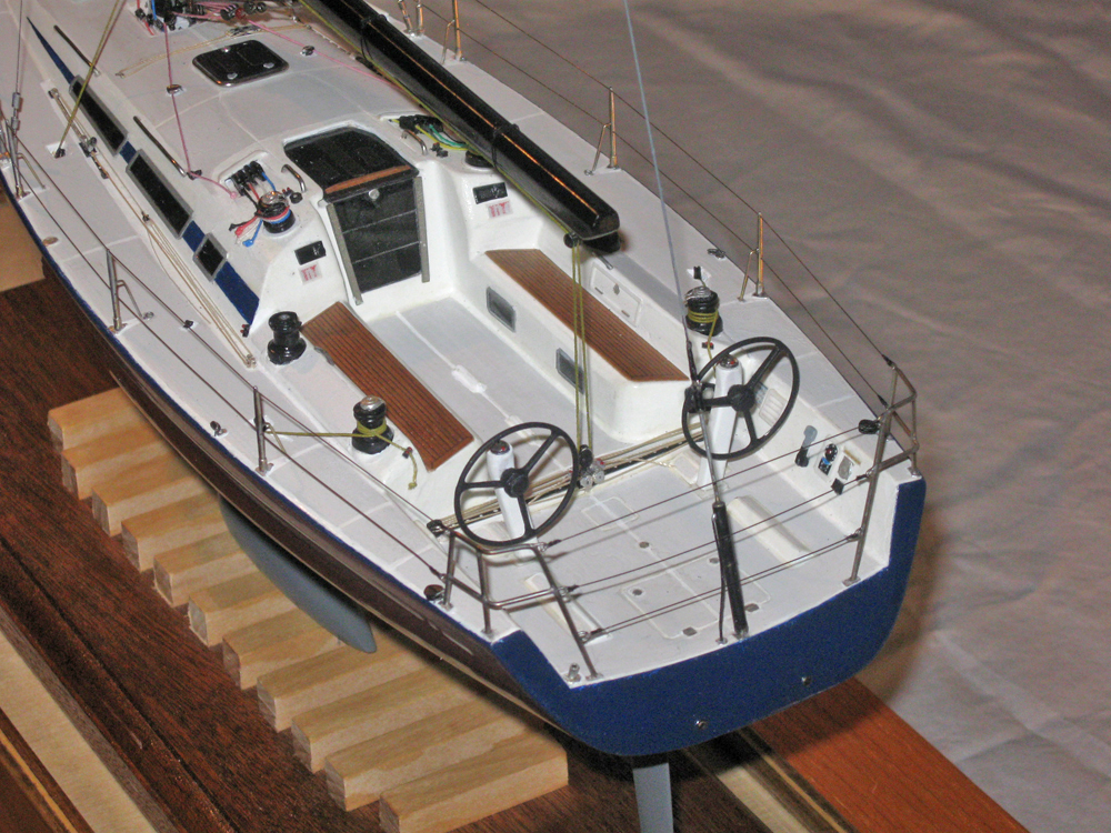
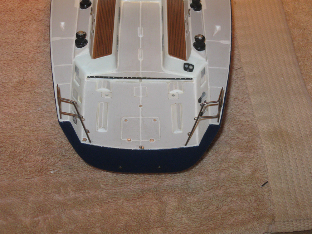
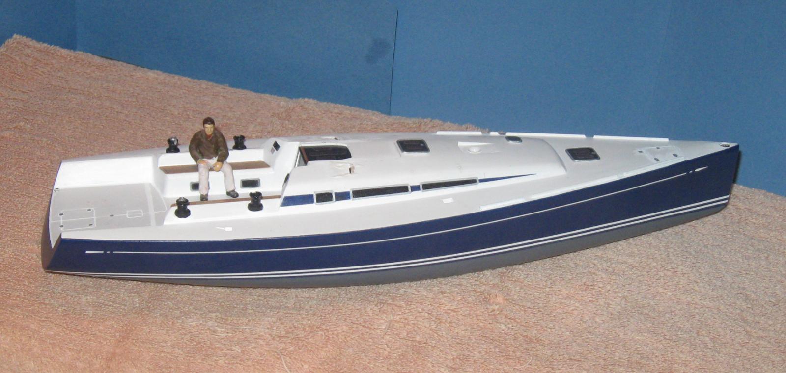
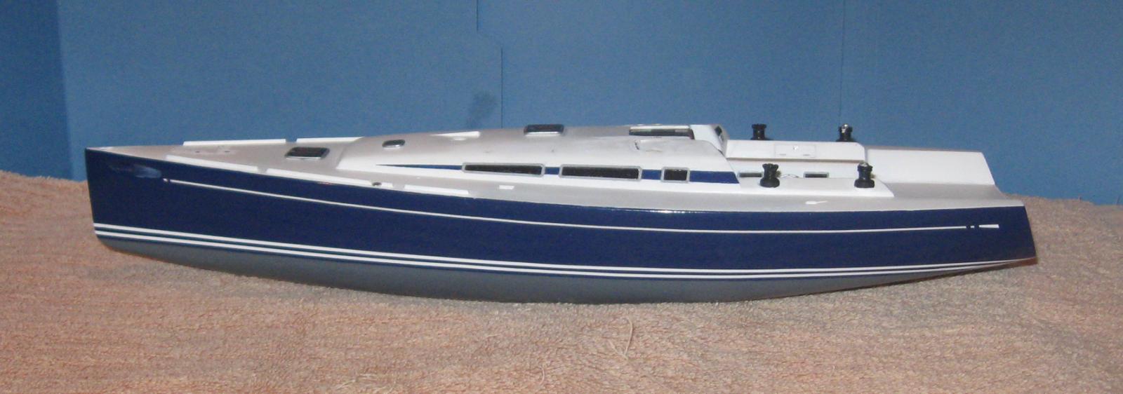
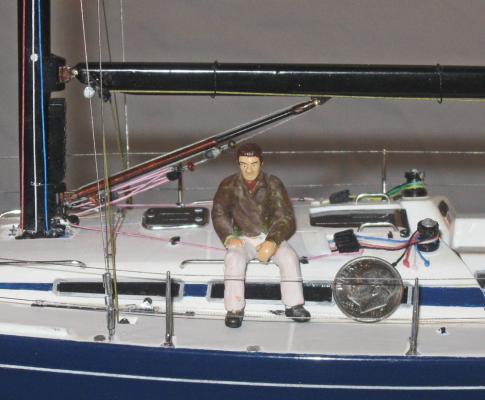
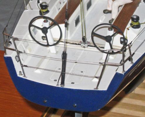
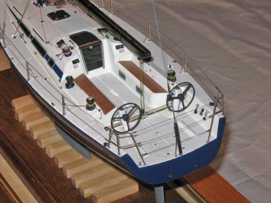
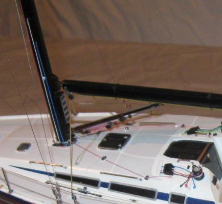
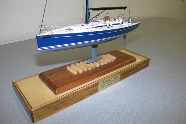
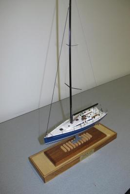
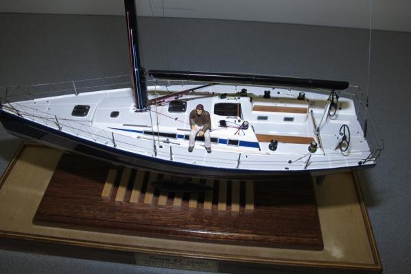
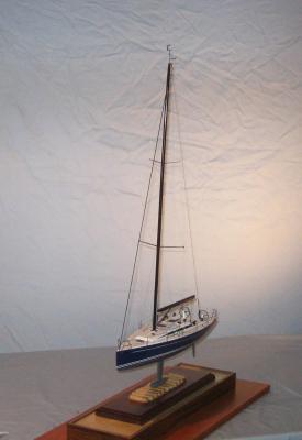
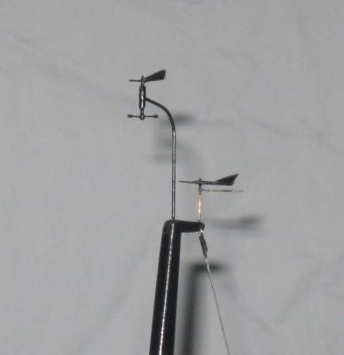
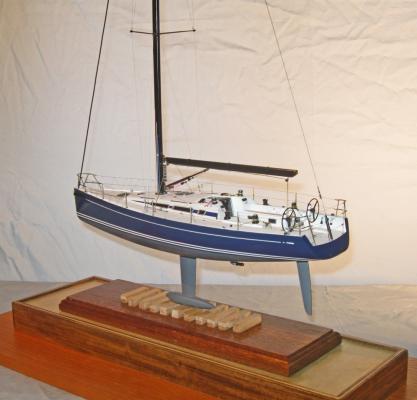
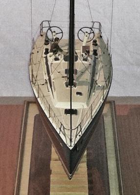
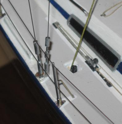
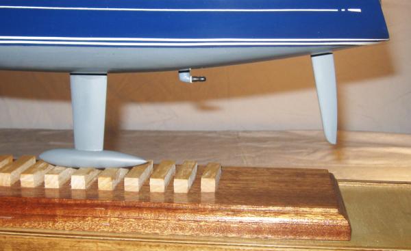
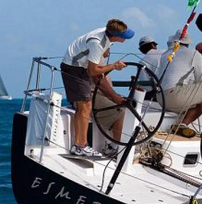
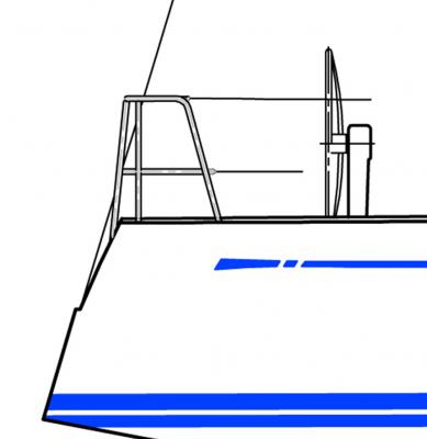
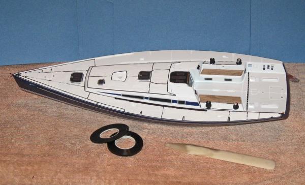
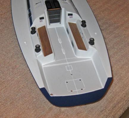
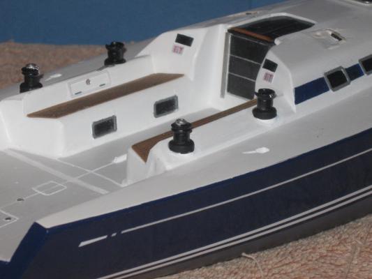
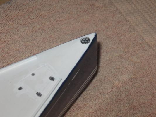
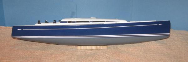
Hello, all – My name is Peter. Dan is working in the shipyard so he asked me to give you a tour of the completed Swan 42. As you can see, I brought with me the world’s largest dime for a bit of size comparison. Since the last segment of this build log we have installed all of the various pieces and subassemblies that were created before, set up the mast, boom and rigging, and installed her on a custom made presentation base ready for delivery. So let me show you around, from bow to stern and bottom to top. Here she is, neatly balanced on her keel bulb. You can see just how tall her rig is. The laminated wood mast rises 62 scale feet from the deck, some 20 feet longer than the hull itself. The spreaders which set up the shrouds are of different lengths and are set at different angles to the mast and to vertical. They are cut from brass sheet, given a layer of epoxy and then faired to their aerodynamic shapes. The standing rigging is 0.012” stainless steel beading wire, which is too small to see in this photo, but will show up later. Here is a view of the entire deck. If Dan did his job well there should be nothing that draws the eye and disrupts the overall impression of being aboard the actual boat. He always says that it has to obey the Rule of 3 – it has to look good from across the room, with detail work that makes you want to see it much closer. Then it has to look good from 3 feet away, like the point of view of this photo, with new and interesting details to see. And then it has to look right from 6 inches away, with even more details that create the ‘texture’ of the actual boat. Of course, the hull and deck have to be symmetrical, so we checked it repeatedly as the mast was being installed. Here is how it came out, viewed from the middle distance. Now let’s move in to the 6 inch viewpoint and look around. At the bow is the pulpit. Dan has explained how this is made from brass tubes that are assembled, soldered and electroplated in chrome. Now it is installed with small feet at the end of each leg made from chrome foil. The jibstay is made up from beading wire with a sleeve of insulation taken from black speaker wire. The furling fittings at top and bottom are simply made up from a short piece of tubing and punched discs as caps. The railing is 0.009” silver beading wire which is turned back on itself and seized with black fly tying thread. The lacing is also fly tying thread, which is looped over the top rail and then goes through some tiny eyebolts set into the deck. The railing stanchions are turned and tapered brass rods with holes drilled for the railings. The support bar is a thinner brass rod soldered to the upright and bent to shape. The base, feet and other fittings are chrome foil. The turnbuckles are made up from sections of 0.04” brass tube that surround and secure the beading wire shrouds to a pair of large deck eyebolts. All of the brass is electroplated like the pulpit. Amidships is the mast, boom and boom support arm (vang?). The running rigging is color coded so that during a race there is no confusion or delay in identifying the right line to haul. The halyards travel mostly inside the mast tube, then emerge not very far above the boom, run down to single blocks at the foot of the mast, through a wide flat tunnel under the cabin roof, up and through the line clutches and then to the winch. Here they are displayed as if for dockside presentation at a regatta. The boom is laminated wood, attached to the mast with a hinged and pivoting fitting of machined brass pieces. The arm is constructed from three pieces of telescoping brass tubing with a double block slung underneath on a brass crescent fitting. The pink vang line runs from the port side camcleat near the aft cabin handrail to a single block secured to the deck, then through a single block on a strap tied to the lower hinge fitting for the boom arm, back and forth between the upper triple block and lower double block (note how the line switches from under/over the triple block to over/under during its second pass), then out a matching set of single blocks and camcleat on the starboard side. All of this is just to get the purchase to haul on the large single block whose line reeves through several pulleys inside the boom arm. The mechanical advantage of this setup must be immense. Much of the rest of the deck details have been shown before, but here they are all installed. The wheel pedestals are set at a 10 degree angle to vertical. The main sheet traveler track and car are rigged for use with the main sheet running up to blocks attached to the fore and aft ends of the boom. At the extreme aft end of the deck is the hydraulic tensioner for the backstay. Again, this is telescoping brass tube and rod, securing the backstay which is heavier beading wire painted to simulate the Kevlar coating. Below the waterline is the keel fin, keel bulb, and rudder. All are carved from basswood, sealed and painted. Between them is the small propeller for powered maneuvering in port. The blades of the prop close like a clamshell when not in use and stay most of the time in this streamlined configuration. Finally, at the very top of the mast are the instruments that read wind direction and speed. This data, along with that from other sensors, is displayed on a series of screens mounted on the mast below the boom that you can see in other photos. So there she is, completed and mounted. Here are a few overall photos. It has received some critical praise from owners of the actual boats and hopefully will be accepted for display in the Model Room of the New York Yacht Club. The shipyard is now moving back in time 300 years from 2005 to 1705 to build the Queen Anne’s Revenge, a 20-gun light frigate that was the flagship of the pirate Edward Teach, known as Blackbeard. It is being excavated underwater at Beaufort Inlet in North Carolina. Go to http://www.qaronline.org/History/TheShipwreck.aspx Look for a build log here in the future.


-
Hi Clare - No need to fake the elevating screw mountings. You obviously have the skills to drill the holes in the cascabels. For my Swan 42' model I had to drill 0.012" holes through 0.040" brass rod. Here is how I did it - maybe it will work for you. First, cobble up a simple wooden board with glued on battens that will snugly hold the cannon barrels (see photo below). Chuck a high speed drill bitt into a Dremel. Start with one that is smaller than you want the final hole to be. Check that the bitt spins exactly on its axis and does not wobble. If it does, rechuck it in another spot. Dip the end of the bitt into household oil. Holding the barrel firmly in its jig, bring the drill bitt into contact with the metal where you want the hole to start and make a small depression. Re-oil the bitt (do this at regular intervals and any time the bitt seems to be working too hard). Take your time and back the bitt out occasionally. I did not have to go through much metal, so I did it with a hand-held Dremel, but you could do it with your Sherline or a Dremel drill press. Once the first hole is made you can expand it to final size with a large bitt. This hole should go much faster and easier than the first. Now you can feed a miniature screw rod through it to make a very realistic elevating screw. Hope this helps. Dan
-
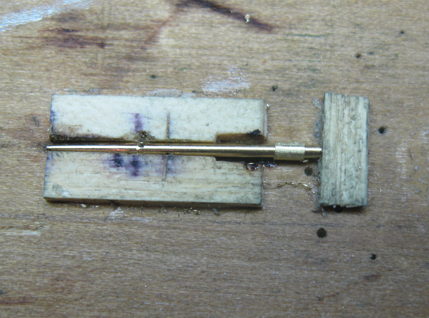
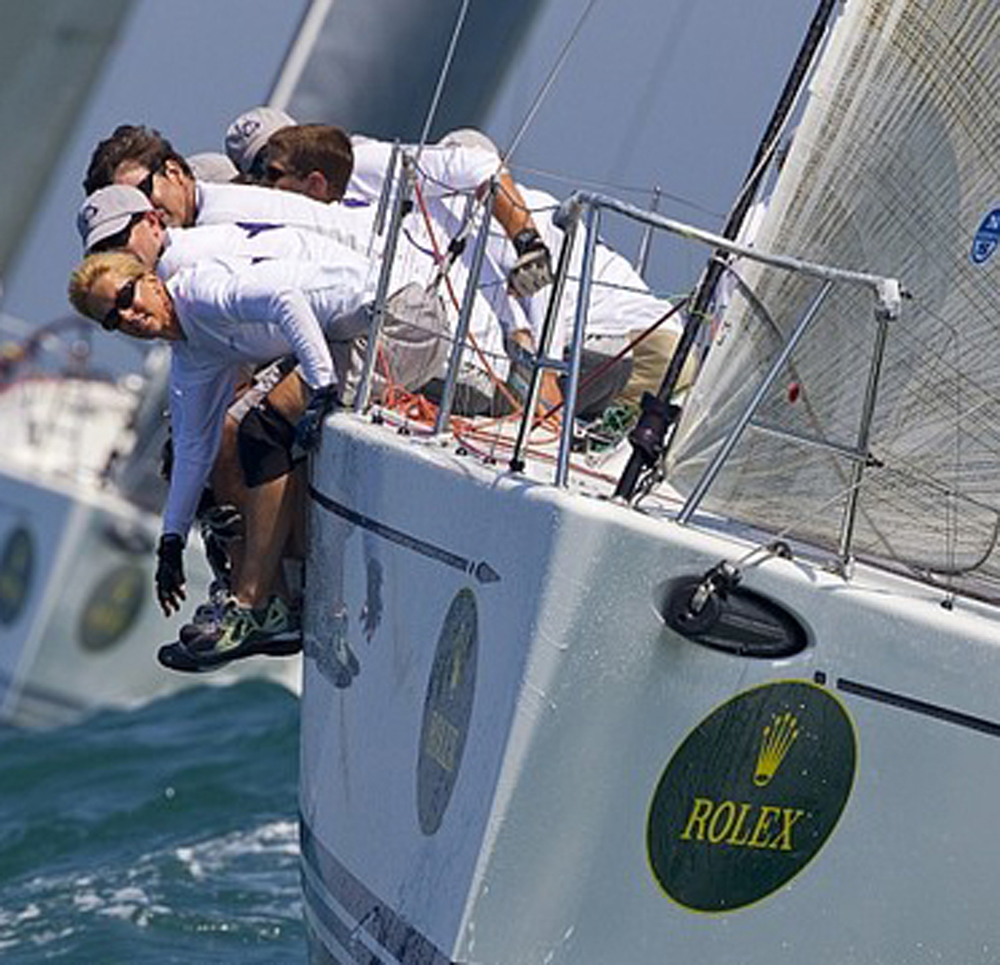
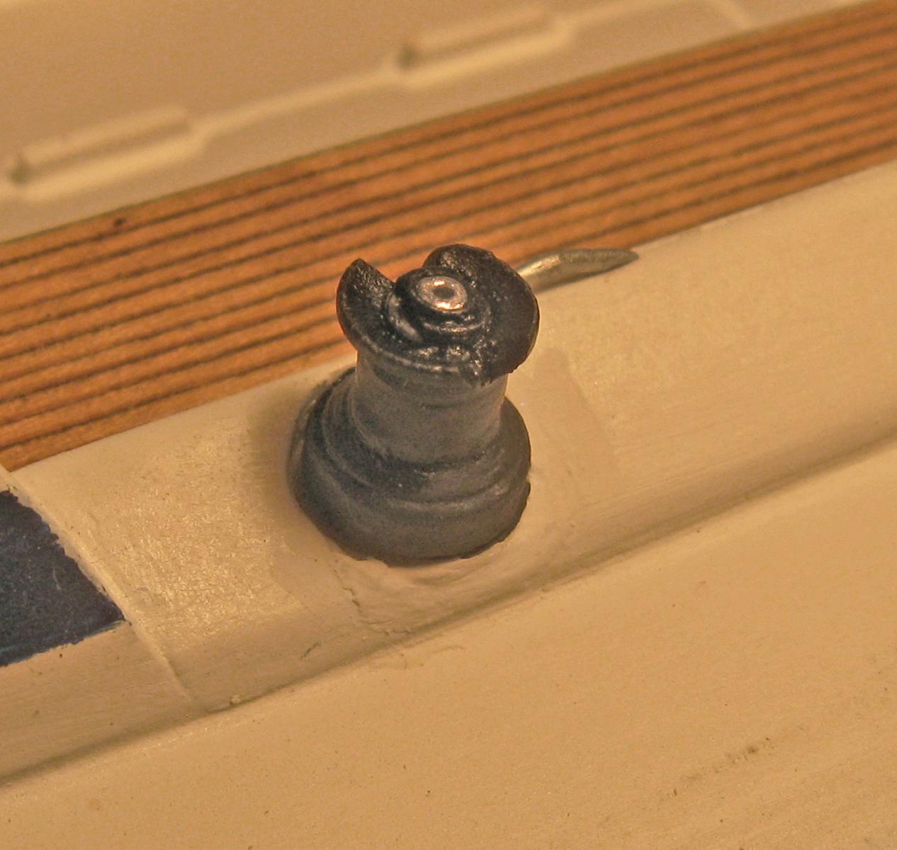
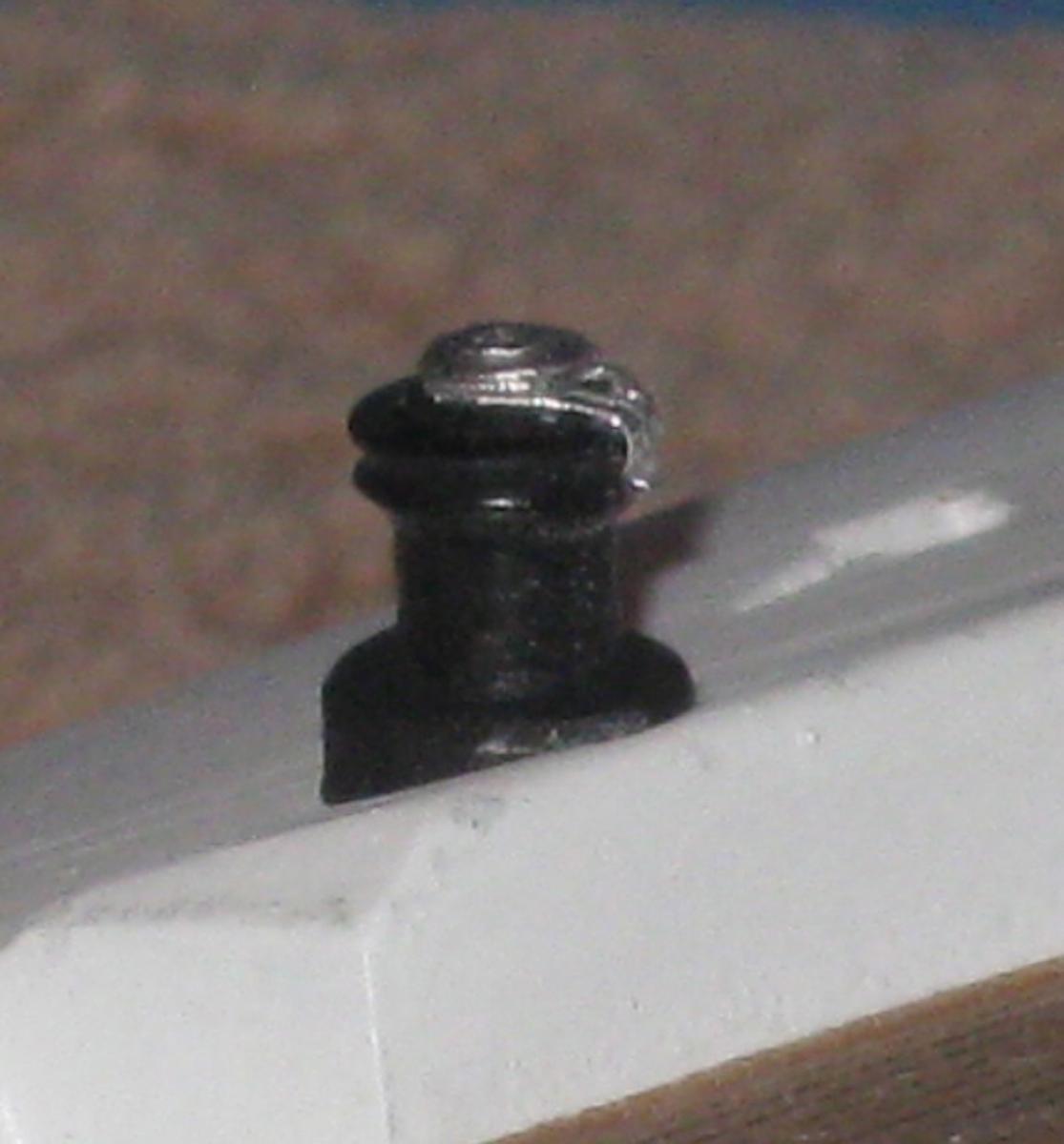
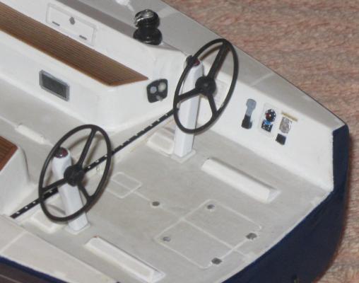
Hi all - Hope the summer is being good to you. Now that the complex railing pieces at the bow and stern are done, I turned to the allegedly simpler deck edge stanchions. They are two feet (scale 3/4") tall, tapered towards the top, and have two through holes for wire railings. Six of the ten have side supports. All have a triangular base piece and a collar at the base. These were initially made from 0.062 brass tube, with the supports from 0.03 rod. Each was cut off to length and the two railing holes were drilled with a 0.0012 (#80) drill. I found this easiest to do with the piece in a simple jig that held it in place with the locations of the holes marked out. I first tried to do the drilling in a miniature drill press, but the bitt kept skipping off the curved surface. Ultimately, I did it by eye, with the drill bitt in a cordless Dremel. Lots of light and magnification are essential. A drop of oil makes the drill cut much more efficiently. After the railing holes were made at locations marked on the jig, the stanchion was turned 90 degrees and a loose drill bitt inserted through the top hole. This held the stanchion in the jig so the 0.020 hole for the support could be drilled perpendicular to the railing holes. With all the holes drilled the stanchion was chucked into a Dremel and the top quarter was tapered to match the boat photo. A full set of ten was made and electroplated. The customer wanted some progress photos, so I temporarily mounted the railings on pegs into the deck. The railings were strung on the starboard side using 0.0095 beading wire. The diagonal lacing at the bow is fly tying line, nominally 0.0030 diameter, although the cross section is not actually round. Here is how it came out. The more I looked at it, however, the less I was satisfied. 0.062 scales out to two inches, which is very close to the actual diameter, but on the model the optical illusion effects made them too heavy. A bit over a day of extra work and another set was made from 0.045 rod and 0.020 supports. Here you can see the difference. And here is how the redone stanchion looks. Note the other small deck details - the padeye at the base of the support, the scammell on deck and the cam-cleat with the red tops on the posts. The next item is the most complex miniature assembly on the model. The main sheet traveller consists of a large block mounted on a car that runs on a track athwart the cockpit with rigging to pull it side to side. It holds down the end of the boom while still allowing it to move from port to starboard. Here you can see one in use on a boat on the water. Here is a picture of the car from the Harken catalog. It consists of a base that rides on the track, three small sheaves on each side and a camcleat on each end, with the large block hooked to an eye in the center. It is just over 9 inches long. Here is the final one for the model. At just over 1/4 inch long it contains 24 parts. These include 1/16 inch diameter punched plastic sheaves, chrome foil base and retaining straps, and camcleats made from 0.025 styrene rod. The spaces around the sheaves are clear to permit the run of rigging. And here it is installed in the cockpit with the rigging running out to double blocks set horizontally at either end. Here is what it will look like when the steering wheels are installed. This was set up as a check to compare to the photos of the actual boats. Now the rest of the small deck details were made and installed. Here is the jib sheet traveller. It is much like the main sheet traveller, but smaller and less complex, although its rigging is more complicated and involves several sister blocks that were made by pinching in the waist of a cast Britannia block from Bluejacket. I settled on these blocks as they are the correct size, strong, and reasonably accurate. A little cleanup, some adjusting and detailing and they are impossible to tell from the actual ones at this size and scale. So here it is, set up on its temporary mounting. Next time we move to the boom, its support arm, and the rigging. I think I see the light at the end of the tunnel, and just hope that it is not a train coming at me. Be well Dan


-
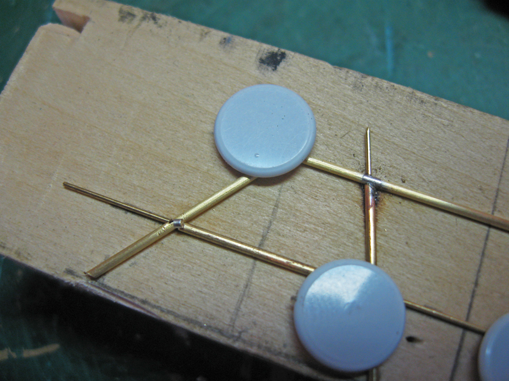
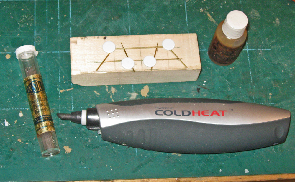
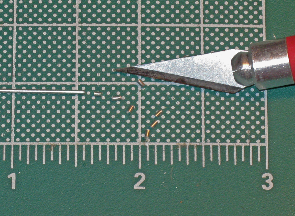
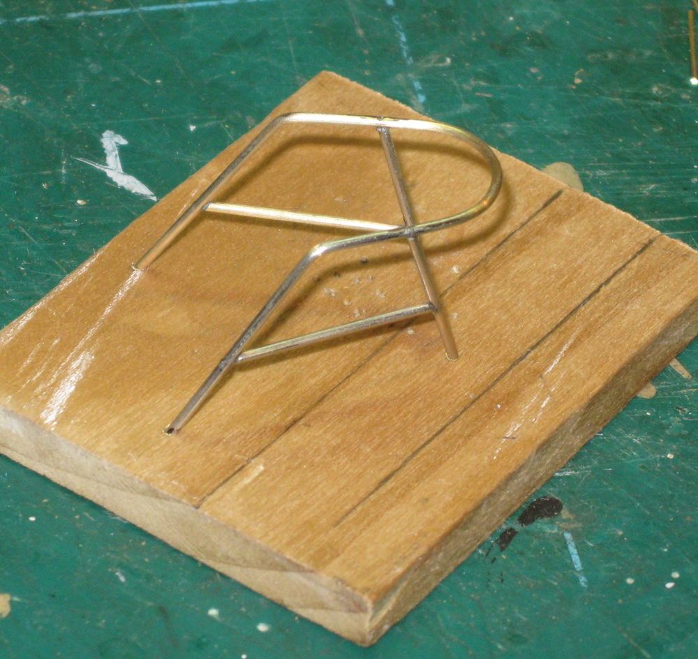
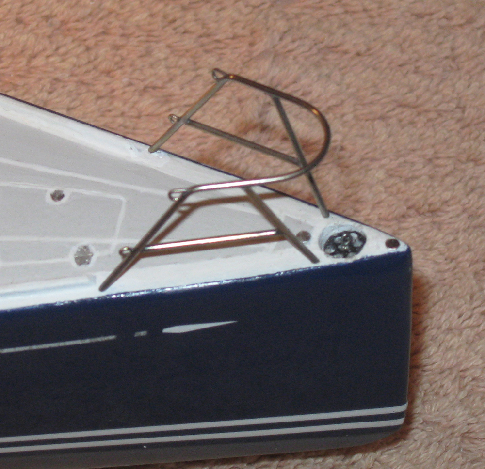
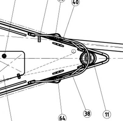
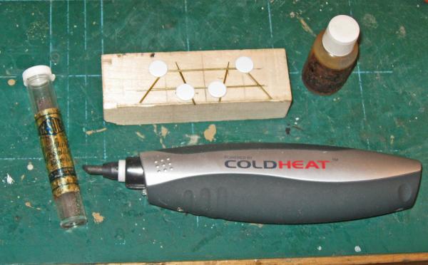
Hi all - Thanks, as always, for the compliments. It is coming along slowly but well, I think. The past several weeks have included the July 4th long holiday and the move of my son and his family from Brooklyn to Michigan, which took me away for some time from the construction yard. Mostly I worked on the railing fixtures at the bow and stern. These are not only complicated three dimensional metal pieces, but require detail soldering and electroplating. Many almost completed, or even fully completed iterations were discarded before acceptable ones were fashioned. Without dwelling too much on past mistakes, here is how it went - The fixture at the bow consists of a top bar that bends around the bow and then bends down to becomes the aft two of the four angled legs that support it. The pair of legs on each side is connected by a low bar as well. Here is what it looks like on the boat. The plans provided gave only a profile view, but I found a detailed deck fitting drawing which shows the plan view. Similarly, the stern fitting has a top bar that bends at almost a right angle around the corner of the transom and becomes a short foreleg and a much longer transom leg, with a vertical piece and horizontal pieces connecting everything together. Here it is on a boat And here from the plans and drawing To match the dimensions, I used brass tubing of 1mm o.d. and internal diameter of 0.020". I could have used solid bar stock, but using tubing provided a lot of advantages during construction. Here is the setup for the bow fixture, surrounded by my soldering tools and supplies. I do most of my soldering with this inexpensive "Cold Heat" device that I heard about through an infomercial on TV several years ago. This is the first time that I am using it for a commissioned model. It is a battery powered resistance soldering unit made for the miniatures or jewelry market. It works by passing an electric current between two carbide electrodes set in a "cloven hoof" configuration with a small gap between the electrodes. When both tips contact metal the current flows between them, heating the metal by induction, or resistance in the metal. For the solder I use Tix brand high-silver content solder along with Tix brand flux. Both can be bought at Micro-Mark and other suppliers. The solder comes in sticks, which is easily cut in pieces about 1/16" long. Although it is easy to cut, once melted and cooled it is quite hard and strong. Also, since it has a lot of silver it electroplates much like the brass tubing. The dimensions of the fixture was figured out from the plans, opened up as if lying flat, and drawn onto a piece of scrap basswood. Pieces of tubing were cut to length and bent to shape. At the appropriate spots I drilled angled holes through the top bar and the forward legs. 0.020" brass rod was fed through the holes, the tubing pieces strung in place, and the entire assembly was secured in place with thumb tacks. In this closeup you can see that at the joint on the left there is a piece of the solder resting on the joint. Actually, the joint was painted with flux, which gets tacky and holds the solder in place till it is heated. Now the Cool Heat tool is turned on and the tips straddle the bar next to the joint. In a few moments the flux sizzles, then the solder softens and sags. Do not remove the heat, but wait until the solder melts completely and forms a shiny dome over the joint. Remove the heat and the solder will flow into the joint, filling and securing it. There is a soldered joint at the right edge of the photo. Once all of the joints have been soldered the extra connecting pieces of the rod were clipped off and the joints were filed to remove any excess solder. Taking a deep breath I folded the piece around a suitably sized dowel to form the rounded 'pulpit' that goes around the bow. Fortunately, all of the joints held. Now the legs were trimmed to final size so the fixture sat level and in the right position. With a wire wheel every bit of the fixture was polished in preparation for chrome electroplating. As with painting or other finishing, the surface preparation is key. The electroplating kit was set up as I described before when making the handrails, and the piece was dipped for only 15 seconds, which gave it a very nice silvery finish after rinsing and polishing with a cloth wheel. And here it is installed on the model. Using tubing also allowed me to insert brass rod into the lower ends of the supporting legs which were bent to drop into holes drilled into the deck. This creates a 4-point mechanical attachment for the piece, which should be enough, even at the vulnerable spot at the extreme bow. The stern fixtures were build up in much the same way. After the design was calculated and drawn, brass tubing was bent to the shape of the top bar and legs. Holes were drilled for the 0.020" rod which was used as an armature to hold the tubing pieces in place. And here are all of the joints soldered. Most are good, but you can see that the joints at the central crossing are a little starved for solder. Flux and another piece of solder were used and heated, and the joint was filled quite easily. The loops for the wire railings are made of the same brass rod as the armature and soldered in place. Now the fixture was bent to its final angle. This is where a number of fully soldered fittings died. The bend of the lower bar is just too close to the central joint, which fails time and again. I finally resorted to leaving off that piece of tubing and bending the top bar alone. Since it is a continuous piece of metal there was no failure. Now the lower bar piece had to be pre-bent, trimmed to size, and set in place with the internal rods. These last joints were soldered to complete the construction. Here are the mirror image fittings, the one on the right has the attachment pins installed. As with the bow fixture, these were cleaned up with a file and then polished with a wheel before electroplating. And here they are set in place. I just have to add some feet to the legs, which will be small pieces of chrome foil and they will be complete. Next I will make up the individual railing posts before turning to the mast and rigging. But I have to do some work on another project the rest of the month, so I will post again in August, when I should be almost done. Until then, be well. Dan


-
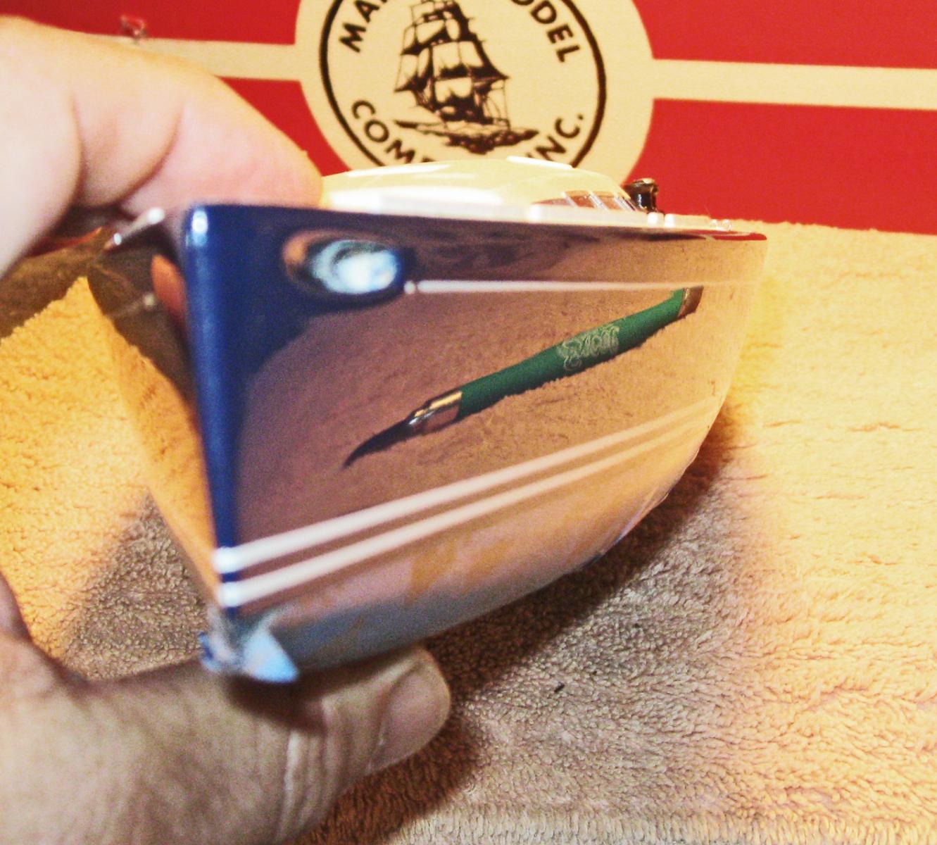
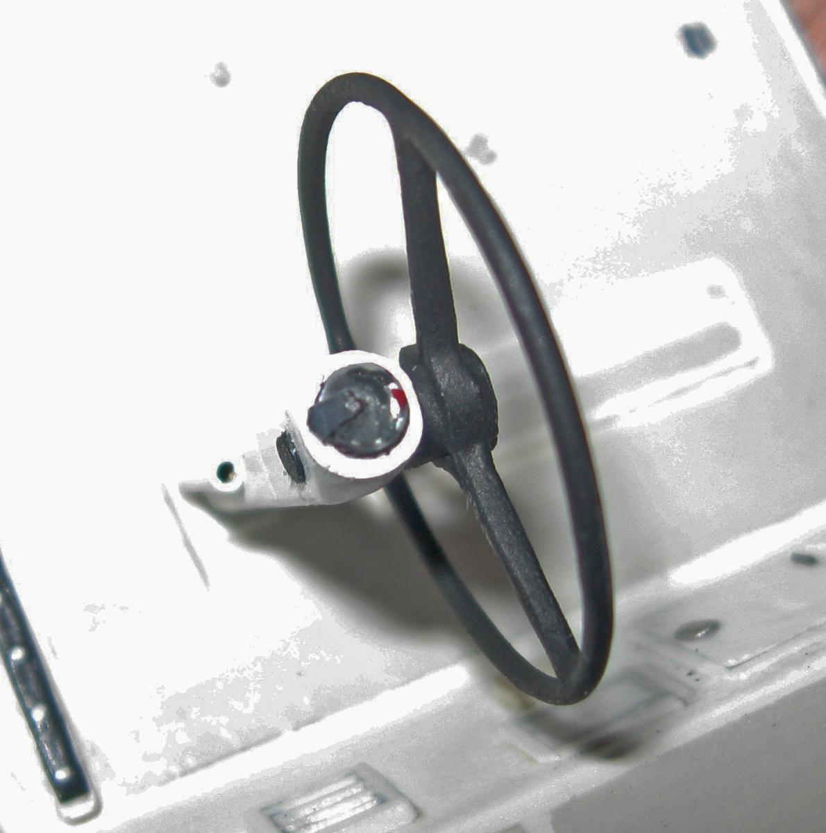
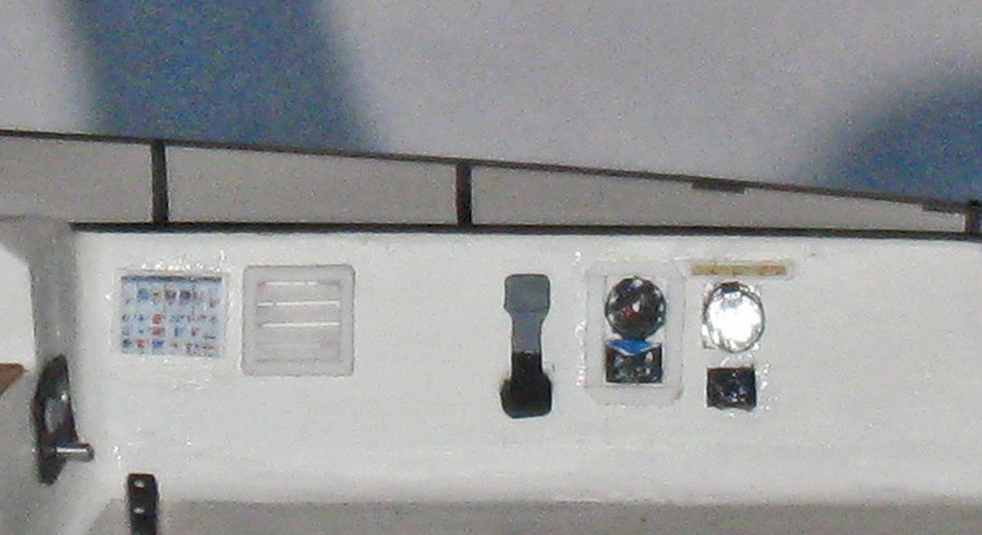
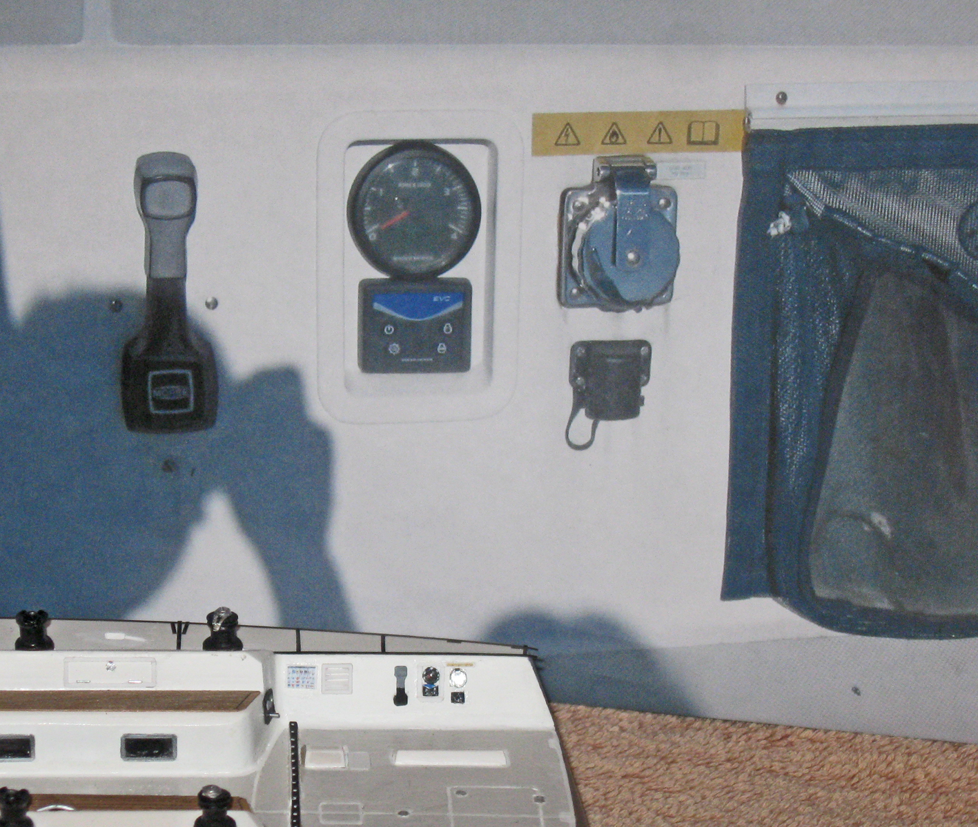
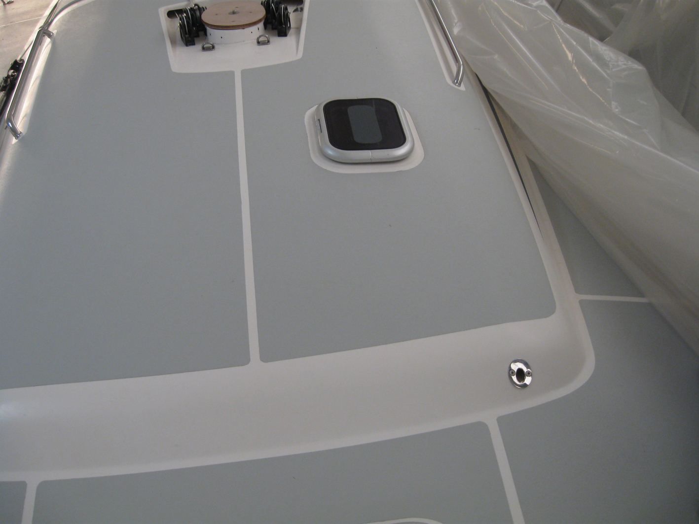
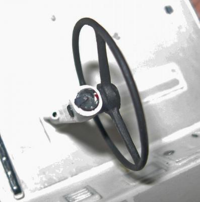
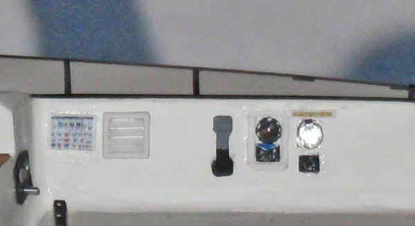
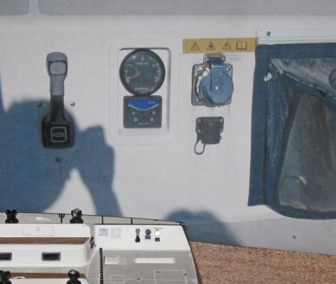
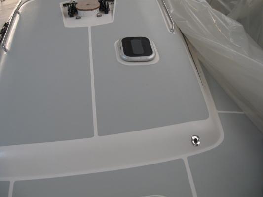
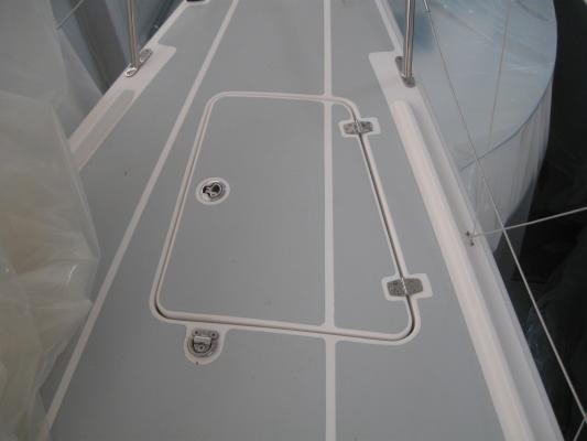
Hi all - The theme of the past two weeks has been - improve, improve, improve, so there is not much new to see. Most of the time was spent on the hull sides. Although they were already good, I wanted an almost mirror finish. Experiments with many gloss coatings, sanding and polishing, finally gave me the finish I wanted. Ultimately it came down to sanding with up to 13,000 grit, several coats of clear gloss acrylic, and a final polishing with jewelers' rouge. Here it is - The non-skid coating process has continued. Here are a few more photos of the masking process using 1/32" and 1/16" vinyl striping tape for the the masking. The bone burnisher was used extensively. However, although the masking was good, it was not perfect. I will be working on it some more in the coming weeks till I am satisfied. This same fate will overtake the three hatch covers. They have gone from 'acceptable' to 'not good enough' as my standards rose. I am satisfied, for now, with the small details in the cockpit. Here are the vent, throttle, guages, and electrical port on the starboard wall of the cockpit, both in miniature and against a photo of the boat. Here are the three-arm wheels mounted on their bent posts. They are still removable at this point until the deck has been redone. On top of the posts is a compass which is 1/8" across. It is made from a drop of clear epoxy whose surface tension gave it the dome shape. You can see the markings through the epoxy although it is much too small to see any numbers, even if I could write that small . . . :-)) One step back and two steps ahead. But as General Patton used to say, "Forward, always forward." Dan
-
Hi all - Thanks for the interest and compliments. Tom - the self tailing fitting is about 1/4" overall. It is made up from three layers of 0.005" chrome shim. The lowest is cut to the shape of the arm, while the upper ones are 1/8" and 1/16" discs. A hole is drilled in the top for the crank handle and the tailing arm is bent and trimmed as needed. It came out pretty well on the fourth try. Dan
-
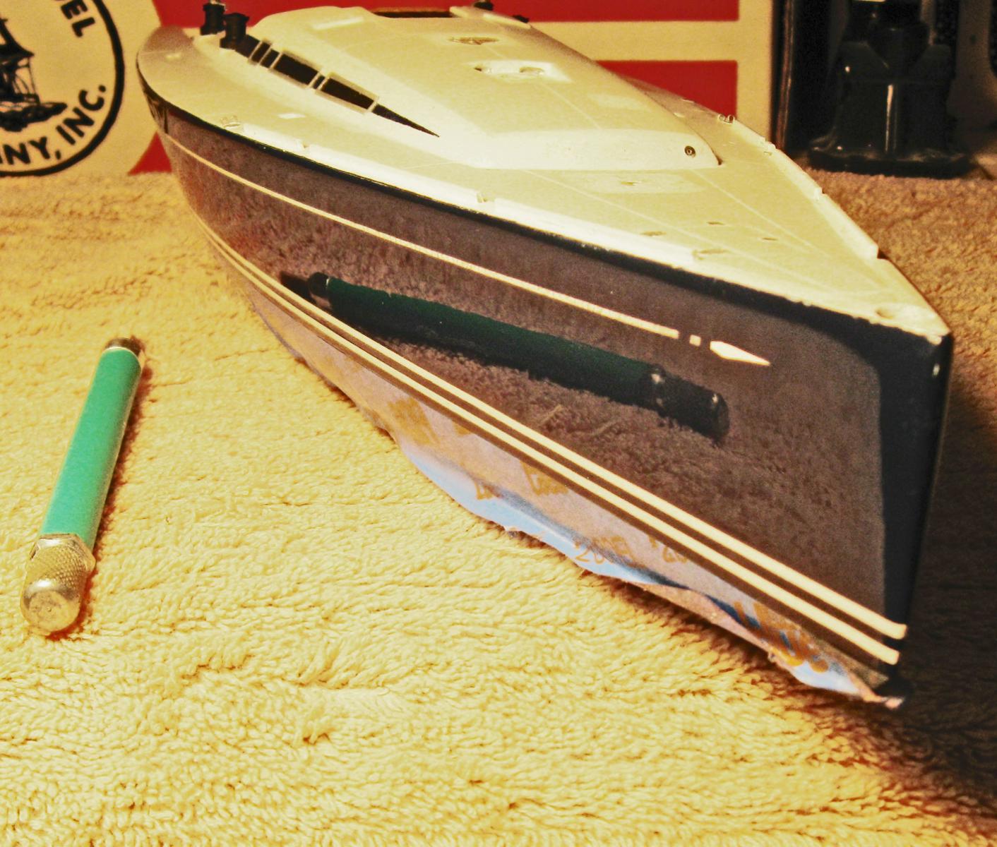
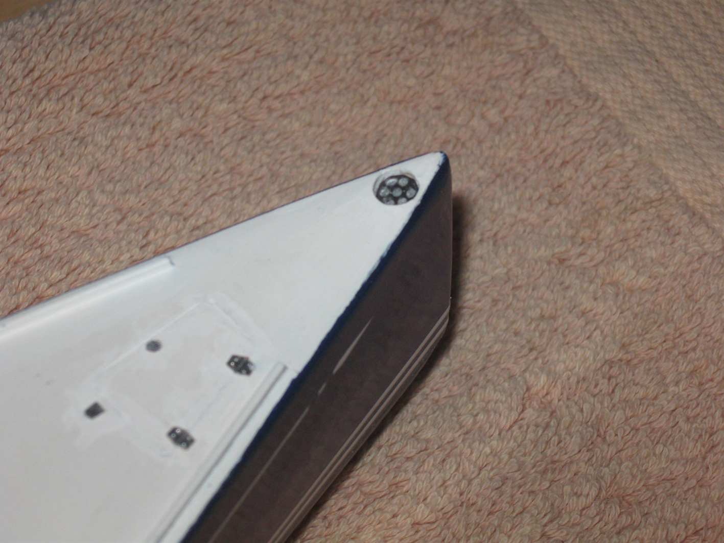
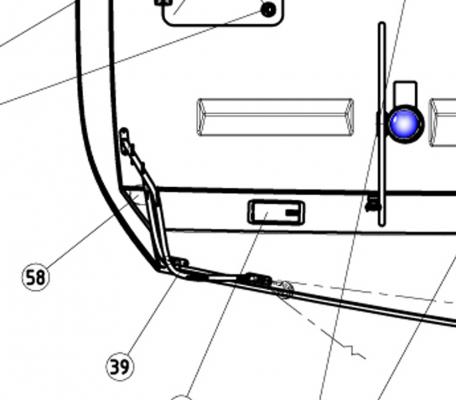
Hi again to those following this log - Progress has been a bit slow the past two weeks. Actually, it went OK, but last week I got to do another site visit to two boats still in the marina, one with the rig set up, and the other fully uncovered. It turned out that a significant amount of work had to be redone because of the new information. More on this later. The greatest progress was on the hull. With the pieces together, as they were last time, the surface could be smoothed, hardened, and smoothed again. Sanding continued down to 600 grit before the first of what turned out to be 6 layers of primer was applied and sanded down to 1000 grit. The waterline for the color separation had been marked with a simple pencil holding jig before the upper and lower hull pieces were glued together, and this line was preserved and redrawn as needed during the priming process. The lower hull was masked at this line with tape, starting with 1/16" width at the line, then wider to cover the lower hull. The deck was similarly masked, starting with thin tape, but then switching to paper toweling held in place by tape. Once everything was set the color coat, a deep blue, was sprayed from a rattle can. Several light coats were applied, given a final sanding, and the final color coats applied. After drying for a full day two white stripes were applied just above the color separation line. These were 1/16" wide striping tape from a company called "Sig" and ordered from a hobby supply house. They are quite opaque, are self-adhesive, and paper backed. Once the paper was removed the stripes were carefully applied as straight as possible. Then they were checked repeatedly and adjusted. There is a small window of open time when the stripes can be adjusted up or down as needed. I used pencil erasers to do this so as not to mar the hull paint. Similarly, a 1/32" wide stripe was applied near the top of the hull following the sheer. This is the logo of the Swan boats, with the arrowhead and tail cut from the wider tape. The arrowhead appears on only the starboard side. On the port side the hole for the spinnaker pole gets in the way. Once in place the hull was given several coats of clear gloss finish to protect it and secure the stripes. Here is how they came out - Once the hull had dried completely I turned to the cockpit. The first technique to master was the non-skid surface. I tried some silkspan which a fellow modeler sent me, as well as tissue papers and other films, but none would adhere to the compound curves necessary. I finally went with acrylic matte paint, as several of you suggested. I got a series of 1/32" masking tapes and laid them out on the white background. Then the non-skid areas could be painted. This worked reasonably well, but some of the paint came up when I went to remove the tape, Ultimately, it became necessary to carefully cut along the edges of the tapes before removing them. Then I repainted the edges of the non-skid areas. This looked fine, until I went to see the boats and found that the color was wrong. I matched what I saw in my photos, but had not counted on the differences in light and how the color came through in the photos. Using a "color preview" set from Benjamin Moore I was able to identify the actual tone and hue. This was made up in a small sample, and the non-skid areas were overpainted the correct shade. On the deck the hinges and latches for the hatches are cut from chrome foil and outlined in white. The boat designers chose to make a small nod to earlier ship construction with bench surfaces in the cockpit made up from wooden strips with 'caulking' lines between them. These were replicated from a product called "Micro-wood" which is a very thin paper-backed veneer. It is so thin that it can go through a common ink-jet printer. I first laid out the design of the benches in the computer and tested size and shape by printing out the design on a sheet of paper. When it was finally correct I taped a piece of the micro-wood over the spot where it printed out, then ran it through again, printing out the design onto the wood. The inked caulking lines were incised into the wood with the back of the tip of a #10 blade guided by a metal straightedge. This essentially tatoos the ink into the wood while scribing grooves that can be felt. Here is the setup - Next on the construction list were the winches that sit in rebates in the bench backs. The dimensions were taken from the catalog of the Harker company, whose products are specified for use on the boats. They were turned from clear acrylic rod to match the catalog images and photos taken on the boats. There are three pair, and none are alike. All are made from black carbon fiber, but the ones furthest aft are somewhat thin with chrome self-tailing tops. The middle ones are thicker, and have no self-tailing feature, just a chrome socket for the hand crank. The ones furthest forward are thinner, self-tailing ones, but have not been turned yet. Another surprise during the site visit was learning that the forestay furling fitting sits in a well at the extreme nose of the boat. This is easy to do when the actual boat is hollow, but not so easy in the solid hull of the model after a lot of work has already happened around it. The well was drilled very carefully, painted, then a plastic plate drilled with seven holes was glued in place to represent the fitting. So, until next time, here I am, contemplating the work done and the work yet to do. The figure is properly to scale, so the size of the boat can be better judged. Aloha Dan


-
Allan - I am working in 1:32 scale, so the micro-beads are probably not necessary, but I will experiment with matte acrylic paint for the large non-skid areas. I find that it is almost impossibly difficult to get the edges of any covering (tissue, silk, etc) as straight and narrow as I need them. See below. I can mask the white with Chartpak tape. I ordered some that is 1/32" wide. Now I have to solve the inside curve problem. Maybe I will just be careful when I paint. Dan
-
No, masking is not my strong suit so it did not occur to me. I am satisfied with the art paper. It is raised rather than etched, but that cannot be seen except with magnification and in glancing light. Dan