


shipmodel
-
Posts
908 -
Joined
-
Last visited
Reputation Activity
-

 shipmodel reacted to mtaylor in Licorne 1755 by mtaylor - 3/16" scale - French Frigate - from Hahn plans - Version 2.0 - TERMINATED
Thanks for the "likes and" comments.
Just a break from building here while dimensioning my Swiss Pear supply for this.
For hull planking, I'm need 4 sizes of wood: 1/32" X 1/8", 3/32" X 3/16", 1/16" X 1/8" and 1/16" X 3/16".
I have an ample supply of planking wood that is +1/16" X +1/8" and +3/32 X +3/16" that I'm converting down. I've been testing out my technique on this and sorting things out. For the first batch of 1/32" X 1/8", what I'll be doing is running it through the thicknesser to get it down to 1/32" (dead on exact) and then running it thought the table saw with a 230T blade to get the exact 1/8" I want.. For those on metric, 1/32" is equal to about 1mm.
I give the raw dimensions as "+" because they're all a tad oversize and the oversize seems to be inconsistent.
I'm attaching two pics of the saw with the wood being run through it. You can see that very little wood is being removed and also how I'm keeping my big paws away from the blade.
I hope to have planking underway pretty soon. In fact, maybe tomorrow, I'll take a break from dimensioning and do the counter. Hmmm... I need some ebony for the stern above the lights so I'll have to do that also.
Overall view:
Close up of blade area:
-
shipmodel reacted to WackoWolf in Licorne 1755 by mtaylor - 3/16" scale - French Frigate - from Hahn plans - Version 2.0 - TERMINATED
ROFLMAO. Like no one ever did that before.
-
 shipmodel got a reaction from CiscoH in Queen Anne's Revenge 1710 by shipmodel - FINISHED - 1/36 scale
Log 29 – lower standing rigging
Two weeks ago there were no masts or rigging set up. The channels weren’t even on.
1
Today, with the invaluable help of JerseyCityFrankie, the lower standing rigging is done and the upper rigging well on its way.
2
Here is how it was done.
First came the channels. They are all situated in the line of the second molding, just under the blue painted bulwarks and above the gunports. In typical fashion they are stylishly curved at each end, with a cap strip that captures the deadeye “chains”. They are located such that the foremost deadeye lines up with the center of the mast. In the photo you can see how I miscalculated this and the main channels had to move aft about half an inch, leaving a gap in the molding that had to be filled later. Unlike English practice which usually had the supports under the channel, French practice at the time was for wooden knees above the platform.
3
For the lower masts, the rule of thumb is that deadeyes are half the diameter of the mast, while for upper masts they are more closely the size of the mast. For this 17mm main mast the deadeyes are 9mm boxwood ones purchased from Model Shipways and stained. Each hole was opened a little and a lanyard groove cut for each hole on an angle to ease the bend in the lanyard line. In my restoration work it is almost invariably true that the rigging line fails at these sharp corners in deadeyes and blocks, so wherever possible I will be preparing the rigging fittings this way.
The deadeye “chains” are not the three links that are seen on later ships, but solid iron straps that are bolted through the hull at the bottom. At the top there is a loop that hooks through a raised section of the deadeye strop. This setup has been seen in contemporary drawings and confirmed by artifacts discovered in the excavation of La Belle, LaSalle’s ship when he explored Texas in 1674. La Belle is a little early and about half the size of the QAR, but the rigging fittings should be similar so I have decided to go with this. I will be taking many cues from the La Belle excavation as reported by Glenn Greico in his Master’s dissertation, available here: http://nautarch.tamu.edu/Theses/pdf-files/Grieco-MA2003.pdf
My deadeye straps were made from brass strip, with a narrow section ground and bent to a hook, then chemically blackened. They are pinned to the hull with half inch roundhead steel nails that are glued into holes that angle upward slightly to counteract what will be some pretty high stresses as the shrouds are tensioned.
4
The metal strops were formed from stiff iron wire. (Yes, there are straps, strips, and strops. Sorry about that, but I’ll try to keep them straight). Here is the jig that I used. It is for the deadeyes in the tops which have long legs to go through the top, but the principle is the same.
5
A length of wire is bent around the middle pin, which is there to keep the loop open for the later hook. The legs pass between the pair of larger pins and are then bent out in a straight line. A deadeye is held hard against the center point and the legs are bent by hand into the groove till they cross at the top. Using the legs as handles the strop is spread apart until the deadeye can be popped out. A bit of epoxy is laid into the strop groove and the deadeye is put back into the strop and rotated as needed to line up properly. The legs of the strop are clipped short and the ends bent down into the groove with pliers. When the epoxy dries they are ready for use. Although the gap in the strop used to worry me, I have never had one open up. Besides, if the stresses are that great, I would rather that the strop open up than have the entire channel pulled up.
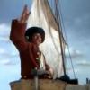
With the deadeyes all strapped and stropped to the channels the rigging could begin. I did this from aft to forward, with one exception. The very first piece of rigging was the gammoning around the bowsprit. This is important because all of the stresses and tensions of the standing rigging are anchored here. You can see the way the lines cross as they wrap from aft to forward on top of the bowsprit, but from forward to aft within the gammon hole in the stem. The gammoning is finished with a few round turns just above the grating in the head.
6
You can also see in the photo that the seat of ease has been lined with lead like the scuppers. I would not otherwise show this feature, but the excavation of the QAR has turned one up, so it has been added.
7
Beginning with the mizzen mast the deadeyes were turned into the shrouds and given three seizings. The shrouds were made from linen line sourced from a pool cue manufacturer who uses the line to make non-slip grips. The line comes in unbleached white, which was dyed with RIT liquid black dye according to the package instructions.
8
As was consistent for almost all ships of this period, whatever their origin, the deadeyes were laced with oiled line. The lacing had to be protected from salt water, but could not be tarred since it must have been adjusted fairly often as the shrouds stretched from the strains of sailing and weather. This has been represented with a dark brown line rather than the darker black of the tarred shrouds.
9
At the mizzen top the shrouds are served as they go over the trestletrees and around the masthead. Under the top are several blocks for the running rigging and for the crojack yard halyard. The mizzen stay is served and an eye worked into the end. A mouse is raised on the stay to form the loop that drops over the masthead and the heads of the shrouds. The mouse is shaped with the bulbous end down, in the French fashion, so the bulb jams against the eye. English practice is to have the tapered “tail” of the mouse slide through the eye until it has no more space to run. I don’t know why there is this difference, or whether one or the other conveys any kind of advantage.
10
At the lower end I ran into a problem. Although never detailed, it is clear that the mizzen stay has to set up to a collar on the main mast. However, if the stay is centered it interferes with the ramshead block and tie for the main spar. I decided to offset the collar to starboard with a bullseye seized into it. A set of double blocks were seized into the lower end of the stay and the upper end of the collar, then joined with a lanyard. The lower end of the collar is belayed to one of the large mast cleats.
11
The shrouds for the main mast are set up much like those of the mizzen. There are five heavy shrouds with large deadeyes, and two more on the aft end of the channel for the topmast shrouds.
12
For the main shrouds the forward one is served its whole length to protect it from chafing by the mainyard sail. The other shrouds are served only where they go around the masthead and then for a short distance below the top where they are seized to each other in pairs. The three futtock shrouds have been hooked into the strops of the upper deadeyes then turned around a futtock stave that is seized across the shrouds. You can also see the pendants that hang below the top, which are served all over with an eye worked into the end. They were used as anchor points for hauling up the ship’s boat, supplies, etc.
12a
Here in a later photo they are shown with a double block hooked into the eye, the running line goes down to a corresponding block at the deck which is hooked into an eyebolt near the base of the mast.
13
These hooks were made up in my usual way, by turning an eye into appropriately sized iron wire using orthodontic wire bending pliers. The wire is then turned back over the pliers and clipped off. For the larger hooks used for the pendants the clipped end was further tapered with a grinding drum, then the tip was recurved as in full sized practice.
14
Aft of the mast a set of catharpins are laced to the futtock staves and pull them inward against the strain of the futtock shrouds. According to R.C. Andersen this diagonal pattern was used by the French, probably to leave space immediately behind the mast for the main yard ties and other rigging lines. They were installed on all three masts as they were rigged.
15
The main stay is set up with an eye and mouse, just as the mizzen stay was. Although this is the largest of the rigging lines on the ship I decided not to worm it, nor to have a preventer stay. I reasoned that a small ship that had been a slaver for several years and was now in the hands of pirates would not have the spare manpower to maintain lines that would not be called on except in battle, which the pirates avoided at all costs. The collar is set up in the French fashion, served all over and anchored around the base of the bowsprit. The two legs are seized together at the bow and then on both sides of the foremast. Large triple blocks are seized into the ends of the stay and collar and laced together.
16
In this close-up you can see the blocks, which the French used rather than hearts favored by the English. You can also see the thumb cleats that secure the collar to the mast on either side.
17
The standing rigging to the foremast is identical to that of the main mast, except that the stay goes to a collar on the bowsprit. You can see most of what has been discussed in this one photo.
18
The fore and main masts had crowsfeet laced from the top to the stay to prevent the lower edge of the topsails from curling under the top and fouling all the lines and blocks that live there. These were made by first shaping the euphroes out of pear. They are about ¾” long, with a strop groove cut in all around the edges. Since there are 16 holes in the forward edges of the tops, the euphroe has 8 corresponding holes. A strop was seized into the groove with the tails left on which were used to attach the euphroe to the stay.
19
The crowsfoot was formed by lacing the line up through the hole in the top closest to the center cleat on the starboard side. A stopper knot under the top prevented it from pulling through, much like the deadeye lanyards. The line laced down and through the top hole in the euphroe, up and over the lip of the top on the port side, down through the first port side hole, and up the second port side hole. It continued down and through the second euphroe hole, up over and down the second starboard hole, and up the third starboard hole. The lacing continued loosely back and forth in this manner until the line reached the outermost starboard hole. All the lines were tightened and a knot was worked close under the top and the excess line snipped off. To strengthen it all the lines were painted with dilute PVA glue.
20
The final element for the lower standing rigging is the ratlines. The line itself was selected to scale out to ¾” diameter, suitable for the weight of a man, and spaced 10mm apart, which converts to 15” in real space. As for tying them, many others have gone over the lacing of ratlines, so I will not repeat that here. Suffice to say that they are attached to the outermost shrouds of each gang with an overhand loop, which makes the smallest bulge around the shroud, and secured to the inner shrouds with clove hitches. This is not nearly as daunting as it may seem. Once a rhythm is established it goes rather quickly, like knitting. Frank and I tied all the ratlines for all the lower shrouds in just four hours. No special effort was made to have the ratlines sag between the shrouds, but they naturally take on a mild curve as the tying proceeds. This can be increased or reduced by gently tugging on the appropriate knots until the desired look is achieved. Once I was happy with the overall look the entire shroud gang was painted with dilute glue and, when the glue was dry, the tails were clipped as close to the shrouds as could be managed.
21
I hope to have another report out before Christmas, with the completion of the standing rigging and the beginning of hanging the spars and sails.
If not, a very Happy Holiday Season to all and I will be back in the New Year.
Dan
-
shipmodel reacted to michael mott in Skipjack by michael mott - 1/8th scale - SMALL - 19 foot open launch
Greg, Mark, Carl and Mark thanks for your encouraging comments about my work, and again to all who have appreciated it quietly.
Moving forward to the control of the clutch I have started to make the forward reverse lever. This lever will need to have some ability to be adjusted.To give just the right amount of pressure to the clutch spring. The geometry of the fulcrum points is critical.
The strength of the coil spring is also one of the items that might need a few reworks to get right as well. The whole physics of springs and their construction is no doubt a science, but from my practical point of reference, a trial and error method will have to suffice. So I will see if it works.
I rummaged through the scrap box until I found the right bit of brass to cut the lever out of. I used the vernier height gauge to lay out the shape, then pre-drilled all the holes while it was rectangular this makes it much easier to get them square to each other.
the cutting was done with a fine blade in the jewelers saw. I have already started to file the surfaces to the final shape.
The keeper rods are now set into the gearbox these were turned up from some free machining 1/8th inch hex stock, at first I left the heads as a hex bolt but they were too big and interfered with the pressure collar. so turned them into cheesehead screws. the spring was wound from some .020 music wire, I used the number drill series of drills as the arbor to find the correct size to finish up with a 3/16th internal bore the third attempt produced the correct diameter, it was a number 21 drill.
The lower pivot point to which the lever connect to will be mounted on the back wall of the oil pan below the prop shaft, and will be able to be threaded forwards and backwards to give the adjustment.
There will be a connecting link from the lever to the clamp on top of the clamp ring.
Michael
-
 shipmodel got a reaction from mtaylor in Licorne 1755 by mtaylor - 3/16" scale - French Frigate - from Hahn plans - Version 2.0 - TERMINATED
Hi Mark -
Really sweet work on the framing. Looks even better enlarged and flipped right side up. Smooth, fair and symmetrical. Not much more you can ask of a set of ribs.
Cherry will work well for planking. I have used it many times. However, I have run into some problems occasionally: Some pieces seem to have been over-dried and are brittle. They splinter rather than cutting cleanly. Make sure your blades are sharp. Also, the color can vary substantially under the final finish even when the unfinished pieces look quite similar. If you will be coppering the lower hull consider using a less expensive, more user friendly wood there.
Looking forward to seeing your progress.
Dan
-
shipmodel reacted to mtaylor in Licorne 1755 by mtaylor - 3/16" scale - French Frigate - from Hahn plans - Version 2.0 - TERMINATED
Hit a big milestone... framing is complete and ready for planking. Well, one minor tweak to the transoms to get smooth run to the counter but that's not going to be a stopper.
Right now, I'm having second thoughts about the bulk of the planking in Swiss Pear and am considering cherry. I'll ponder a bit more.....
-
shipmodel reacted to Omega1234 in Licorne 1755 by mtaylor - 3/16" scale - French Frigate - from Hahn plans - Version 2.0 - TERMINATED
Very nice Mark! Off topic, though...I notice you're a Special Contributor now, whereas I thought you were a Moderator. Have you been promoted?
-
shipmodel reacted to michael mott in Skipjack by michael mott - 1/8th scale - SMALL - 19 foot open launch
Ed, and Jack, thank you for your kind comments. and for all who added likes.
I had to make a new band clamp because the tabs were not wide enough to bolt it to the pan. the new one was machined from a solid ring and then a lot of fiddling and filing to get it to spring just right.
I also whipped up a flywheel because it is tough on my fingertips turning the 1/8th shaft all the time to test stuff.
Today I worked on the clutch, it was a bit of a design build affair following the general principles, the gearbox and clutch will be underneath the cover so only the top of the linkage and the lever will need to be as accurate as possible to keep the appearance of the engine looking as the full size engine.
I abandoned the cap screw hex and made a hex broach from a 3/16 allen key. first I heated it up and let it cool slowly to take the hardness out of it, then cut a taper on one end of the hex. Next I added the beveled slots to create the cutting faces. I ended up making a second one because I forgot to temper the first one after re hardening it, it cut the first hex through about a half inch length of brass stock, and then I tried a longer piece of brass and it shattered into three.
Pushing the second one with the vice rather than using the hammer which is how I managed to wreck the first one.
At the back end of the broach I reduced the diameter before it was hardened so that I could part off the disks one at a time, as the broach was forced through, each time the broach reached the end I put it back in the lathe parted off another disc
Next I turned a few discs of mild steel off a blank that had been pre drilled for the keeper rods. the steel discs are 5/8 diameter and .020 thick the brass plates are 5/16 diameter and .040 thick. the steel discs will be fixed to the gearbox and rotate about the hex the hex will be pinned to the prop shaft and the brass plated will spin with the hex
.
Here they are test fitted for size, the wide brass collar is also keyed to the prop shaft and will be the pushing element to squeeze the plates together.
Time for bed
Michael
-
shipmodel reacted to michael mott in Skipjack by michael mott - 1/8th scale - SMALL - 19 foot open launch
Remco, Steve, Joe, and Row thanks for your very kind remarks. Thanks to all who pressed the like button as well.
I finished up the clamp ring today and made the actuating lever to open and close the ring, it is quite tiny but was manageable. in order to get the widths that I wanted quickly I spun up a disc on the lathe, bored out the centre hole on the lathe then stood up the rod with the disc still attached in the vice on the mill and offset the other hole .156" then took it back to the lathe and parted it off then used the jewelers saw to cut out the crank.
Then cleaned it up with some files, then polished it up to a rouge finish and beveled the hub to create the cam.
Here it is set in position with the spring loaded bolt in the open position the width of the flanges at the bolt are .290"
And here with the lever in the closed position the width of the flange at the bolt is .250" locking the gearbox casing.
This is how it works
next the rear cam locking collar.
Michael
-
 shipmodel got a reaction from popash42 in Queen Anne's Revenge 1710 by shipmodel - FINISHED - 1/36 scale
Log 29 – lower standing rigging
Two weeks ago there were no masts or rigging set up. The channels weren’t even on.
1
Today, with the invaluable help of JerseyCityFrankie, the lower standing rigging is done and the upper rigging well on its way.
2
Here is how it was done.
First came the channels. They are all situated in the line of the second molding, just under the blue painted bulwarks and above the gunports. In typical fashion they are stylishly curved at each end, with a cap strip that captures the deadeye “chains”. They are located such that the foremost deadeye lines up with the center of the mast. In the photo you can see how I miscalculated this and the main channels had to move aft about half an inch, leaving a gap in the molding that had to be filled later. Unlike English practice which usually had the supports under the channel, French practice at the time was for wooden knees above the platform.
3
For the lower masts, the rule of thumb is that deadeyes are half the diameter of the mast, while for upper masts they are more closely the size of the mast. For this 17mm main mast the deadeyes are 9mm boxwood ones purchased from Model Shipways and stained. Each hole was opened a little and a lanyard groove cut for each hole on an angle to ease the bend in the lanyard line. In my restoration work it is almost invariably true that the rigging line fails at these sharp corners in deadeyes and blocks, so wherever possible I will be preparing the rigging fittings this way.
The deadeye “chains” are not the three links that are seen on later ships, but solid iron straps that are bolted through the hull at the bottom. At the top there is a loop that hooks through a raised section of the deadeye strop. This setup has been seen in contemporary drawings and confirmed by artifacts discovered in the excavation of La Belle, LaSalle’s ship when he explored Texas in 1674. La Belle is a little early and about half the size of the QAR, but the rigging fittings should be similar so I have decided to go with this. I will be taking many cues from the La Belle excavation as reported by Glenn Greico in his Master’s dissertation, available here: http://nautarch.tamu.edu/Theses/pdf-files/Grieco-MA2003.pdf
My deadeye straps were made from brass strip, with a narrow section ground and bent to a hook, then chemically blackened. They are pinned to the hull with half inch roundhead steel nails that are glued into holes that angle upward slightly to counteract what will be some pretty high stresses as the shrouds are tensioned.
4
The metal strops were formed from stiff iron wire. (Yes, there are straps, strips, and strops. Sorry about that, but I’ll try to keep them straight). Here is the jig that I used. It is for the deadeyes in the tops which have long legs to go through the top, but the principle is the same.
5
A length of wire is bent around the middle pin, which is there to keep the loop open for the later hook. The legs pass between the pair of larger pins and are then bent out in a straight line. A deadeye is held hard against the center point and the legs are bent by hand into the groove till they cross at the top. Using the legs as handles the strop is spread apart until the deadeye can be popped out. A bit of epoxy is laid into the strop groove and the deadeye is put back into the strop and rotated as needed to line up properly. The legs of the strop are clipped short and the ends bent down into the groove with pliers. When the epoxy dries they are ready for use. Although the gap in the strop used to worry me, I have never had one open up. Besides, if the stresses are that great, I would rather that the strop open up than have the entire channel pulled up.
With the deadeyes all strapped and stropped to the channels the rigging could begin. I did this from aft to forward, with one exception. The very first piece of rigging was the gammoning around the bowsprit. This is important because all of the stresses and tensions of the standing rigging are anchored here. You can see the way the lines cross as they wrap from aft to forward on top of the bowsprit, but from forward to aft within the gammon hole in the stem. The gammoning is finished with a few round turns just above the grating in the head.
6
You can also see in the photo that the seat of ease has been lined with lead like the scuppers. I would not otherwise show this feature, but the excavation of the QAR has turned one up, so it has been added.
7
Beginning with the mizzen mast the deadeyes were turned into the shrouds and given three seizings. The shrouds were made from linen line sourced from a pool cue manufacturer who uses the line to make non-slip grips. The line comes in unbleached white, which was dyed with RIT liquid black dye according to the package instructions.
8
As was consistent for almost all ships of this period, whatever their origin, the deadeyes were laced with oiled line. The lacing had to be protected from salt water, but could not be tarred since it must have been adjusted fairly often as the shrouds stretched from the strains of sailing and weather. This has been represented with a dark brown line rather than the darker black of the tarred shrouds.
9
At the mizzen top the shrouds are served as they go over the trestletrees and around the masthead. Under the top are several blocks for the running rigging and for the crojack yard halyard. The mizzen stay is served and an eye worked into the end. A mouse is raised on the stay to form the loop that drops over the masthead and the heads of the shrouds. The mouse is shaped with the bulbous end down, in the French fashion, so the bulb jams against the eye. English practice is to have the tapered “tail” of the mouse slide through the eye until it has no more space to run. I don’t know why there is this difference, or whether one or the other conveys any kind of advantage.
10
At the lower end I ran into a problem. Although never detailed, it is clear that the mizzen stay has to set up to a collar on the main mast. However, if the stay is centered it interferes with the ramshead block and tie for the main spar. I decided to offset the collar to starboard with a bullseye seized into it. A set of double blocks were seized into the lower end of the stay and the upper end of the collar, then joined with a lanyard. The lower end of the collar is belayed to one of the large mast cleats.
11
The shrouds for the main mast are set up much like those of the mizzen. There are five heavy shrouds with large deadeyes, and two more on the aft end of the channel for the topmast shrouds.
12
For the main shrouds the forward one is served its whole length to protect it from chafing by the mainyard sail. The other shrouds are served only where they go around the masthead and then for a short distance below the top where they are seized to each other in pairs. The three futtock shrouds have been hooked into the strops of the upper deadeyes then turned around a futtock stave that is seized across the shrouds. You can also see the pendants that hang below the top, which are served all over with an eye worked into the end. They were used as anchor points for hauling up the ship’s boat, supplies, etc.
12a
Here in a later photo they are shown with a double block hooked into the eye, the running line goes down to a corresponding block at the deck which is hooked into an eyebolt near the base of the mast.
13
These hooks were made up in my usual way, by turning an eye into appropriately sized iron wire using orthodontic wire bending pliers. The wire is then turned back over the pliers and clipped off. For the larger hooks used for the pendants the clipped end was further tapered with a grinding drum, then the tip was recurved as in full sized practice.
14
Aft of the mast a set of catharpins are laced to the futtock staves and pull them inward against the strain of the futtock shrouds. According to R.C. Andersen this diagonal pattern was used by the French, probably to leave space immediately behind the mast for the main yard ties and other rigging lines. They were installed on all three masts as they were rigged.
15
The main stay is set up with an eye and mouse, just as the mizzen stay was. Although this is the largest of the rigging lines on the ship I decided not to worm it, nor to have a preventer stay. I reasoned that a small ship that had been a slaver for several years and was now in the hands of pirates would not have the spare manpower to maintain lines that would not be called on except in battle, which the pirates avoided at all costs. The collar is set up in the French fashion, served all over and anchored around the base of the bowsprit. The two legs are seized together at the bow and then on both sides of the foremast. Large triple blocks are seized into the ends of the stay and collar and laced together.
16
In this close-up you can see the blocks, which the French used rather than hearts favored by the English. You can also see the thumb cleats that secure the collar to the mast on either side.
17
The standing rigging to the foremast is identical to that of the main mast, except that the stay goes to a collar on the bowsprit. You can see most of what has been discussed in this one photo.
18
The fore and main masts had crowsfeet laced from the top to the stay to prevent the lower edge of the topsails from curling under the top and fouling all the lines and blocks that live there. These were made by first shaping the euphroes out of pear. They are about ¾” long, with a strop groove cut in all around the edges. Since there are 16 holes in the forward edges of the tops, the euphroe has 8 corresponding holes. A strop was seized into the groove with the tails left on which were used to attach the euphroe to the stay.
19
The crowsfoot was formed by lacing the line up through the hole in the top closest to the center cleat on the starboard side. A stopper knot under the top prevented it from pulling through, much like the deadeye lanyards. The line laced down and through the top hole in the euphroe, up and over the lip of the top on the port side, down through the first port side hole, and up the second port side hole. It continued down and through the second euphroe hole, up over and down the second starboard hole, and up the third starboard hole. The lacing continued loosely back and forth in this manner until the line reached the outermost starboard hole. All the lines were tightened and a knot was worked close under the top and the excess line snipped off. To strengthen it all the lines were painted with dilute PVA glue.
20
The final element for the lower standing rigging is the ratlines. The line itself was selected to scale out to ¾” diameter, suitable for the weight of a man, and spaced 10mm apart, which converts to 15” in real space. As for tying them, many others have gone over the lacing of ratlines, so I will not repeat that here. Suffice to say that they are attached to the outermost shrouds of each gang with an overhand loop, which makes the smallest bulge around the shroud, and secured to the inner shrouds with clove hitches. This is not nearly as daunting as it may seem. Once a rhythm is established it goes rather quickly, like knitting. Frank and I tied all the ratlines for all the lower shrouds in just four hours. No special effort was made to have the ratlines sag between the shrouds, but they naturally take on a mild curve as the tying proceeds. This can be increased or reduced by gently tugging on the appropriate knots until the desired look is achieved. Once I was happy with the overall look the entire shroud gang was painted with dilute glue and, when the glue was dry, the tails were clipped as close to the shrouds as could be managed.
21
I hope to have another report out before Christmas, with the completion of the standing rigging and the beginning of hanging the spars and sails.
If not, a very Happy Holiday Season to all and I will be back in the New Year.
Dan
-
 shipmodel got a reaction from archjofo in Queen Anne's Revenge 1710 by shipmodel - FINISHED - 1/36 scale
Log 29 – lower standing rigging
Two weeks ago there were no masts or rigging set up. The channels weren’t even on.
1
Today, with the invaluable help of JerseyCityFrankie, the lower standing rigging is done and the upper rigging well on its way.
2
Here is how it was done.
First came the channels. They are all situated in the line of the second molding, just under the blue painted bulwarks and above the gunports. In typical fashion they are stylishly curved at each end, with a cap strip that captures the deadeye “chains”. They are located such that the foremost deadeye lines up with the center of the mast. In the photo you can see how I miscalculated this and the main channels had to move aft about half an inch, leaving a gap in the molding that had to be filled later. Unlike English practice which usually had the supports under the channel, French practice at the time was for wooden knees above the platform.
3
For the lower masts, the rule of thumb is that deadeyes are half the diameter of the mast, while for upper masts they are more closely the size of the mast. For this 17mm main mast the deadeyes are 9mm boxwood ones purchased from Model Shipways and stained. Each hole was opened a little and a lanyard groove cut for each hole on an angle to ease the bend in the lanyard line. In my restoration work it is almost invariably true that the rigging line fails at these sharp corners in deadeyes and blocks, so wherever possible I will be preparing the rigging fittings this way.
The deadeye “chains” are not the three links that are seen on later ships, but solid iron straps that are bolted through the hull at the bottom. At the top there is a loop that hooks through a raised section of the deadeye strop. This setup has been seen in contemporary drawings and confirmed by artifacts discovered in the excavation of La Belle, LaSalle’s ship when he explored Texas in 1674. La Belle is a little early and about half the size of the QAR, but the rigging fittings should be similar so I have decided to go with this. I will be taking many cues from the La Belle excavation as reported by Glenn Greico in his Master’s dissertation, available here: http://nautarch.tamu.edu/Theses/pdf-files/Grieco-MA2003.pdf
My deadeye straps were made from brass strip, with a narrow section ground and bent to a hook, then chemically blackened. They are pinned to the hull with half inch roundhead steel nails that are glued into holes that angle upward slightly to counteract what will be some pretty high stresses as the shrouds are tensioned.
4
The metal strops were formed from stiff iron wire. (Yes, there are straps, strips, and strops. Sorry about that, but I’ll try to keep them straight). Here is the jig that I used. It is for the deadeyes in the tops which have long legs to go through the top, but the principle is the same.
5
A length of wire is bent around the middle pin, which is there to keep the loop open for the later hook. The legs pass between the pair of larger pins and are then bent out in a straight line. A deadeye is held hard against the center point and the legs are bent by hand into the groove till they cross at the top. Using the legs as handles the strop is spread apart until the deadeye can be popped out. A bit of epoxy is laid into the strop groove and the deadeye is put back into the strop and rotated as needed to line up properly. The legs of the strop are clipped short and the ends bent down into the groove with pliers. When the epoxy dries they are ready for use. Although the gap in the strop used to worry me, I have never had one open up. Besides, if the stresses are that great, I would rather that the strop open up than have the entire channel pulled up.
With the deadeyes all strapped and stropped to the channels the rigging could begin. I did this from aft to forward, with one exception. The very first piece of rigging was the gammoning around the bowsprit. This is important because all of the stresses and tensions of the standing rigging are anchored here. You can see the way the lines cross as they wrap from aft to forward on top of the bowsprit, but from forward to aft within the gammon hole in the stem. The gammoning is finished with a few round turns just above the grating in the head.
6
You can also see in the photo that the seat of ease has been lined with lead like the scuppers. I would not otherwise show this feature, but the excavation of the QAR has turned one up, so it has been added.
7
Beginning with the mizzen mast the deadeyes were turned into the shrouds and given three seizings. The shrouds were made from linen line sourced from a pool cue manufacturer who uses the line to make non-slip grips. The line comes in unbleached white, which was dyed with RIT liquid black dye according to the package instructions.
8
As was consistent for almost all ships of this period, whatever their origin, the deadeyes were laced with oiled line. The lacing had to be protected from salt water, but could not be tarred since it must have been adjusted fairly often as the shrouds stretched from the strains of sailing and weather. This has been represented with a dark brown line rather than the darker black of the tarred shrouds.
9
At the mizzen top the shrouds are served as they go over the trestletrees and around the masthead. Under the top are several blocks for the running rigging and for the crojack yard halyard. The mizzen stay is served and an eye worked into the end. A mouse is raised on the stay to form the loop that drops over the masthead and the heads of the shrouds. The mouse is shaped with the bulbous end down, in the French fashion, so the bulb jams against the eye. English practice is to have the tapered “tail” of the mouse slide through the eye until it has no more space to run. I don’t know why there is this difference, or whether one or the other conveys any kind of advantage.
10
At the lower end I ran into a problem. Although never detailed, it is clear that the mizzen stay has to set up to a collar on the main mast. However, if the stay is centered it interferes with the ramshead block and tie for the main spar. I decided to offset the collar to starboard with a bullseye seized into it. A set of double blocks were seized into the lower end of the stay and the upper end of the collar, then joined with a lanyard. The lower end of the collar is belayed to one of the large mast cleats.
11
The shrouds for the main mast are set up much like those of the mizzen. There are five heavy shrouds with large deadeyes, and two more on the aft end of the channel for the topmast shrouds.
12
For the main shrouds the forward one is served its whole length to protect it from chafing by the mainyard sail. The other shrouds are served only where they go around the masthead and then for a short distance below the top where they are seized to each other in pairs. The three futtock shrouds have been hooked into the strops of the upper deadeyes then turned around a futtock stave that is seized across the shrouds. You can also see the pendants that hang below the top, which are served all over with an eye worked into the end. They were used as anchor points for hauling up the ship’s boat, supplies, etc.
12a
Here in a later photo they are shown with a double block hooked into the eye, the running line goes down to a corresponding block at the deck which is hooked into an eyebolt near the base of the mast.
13
These hooks were made up in my usual way, by turning an eye into appropriately sized iron wire using orthodontic wire bending pliers. The wire is then turned back over the pliers and clipped off. For the larger hooks used for the pendants the clipped end was further tapered with a grinding drum, then the tip was recurved as in full sized practice.
14
Aft of the mast a set of catharpins are laced to the futtock staves and pull them inward against the strain of the futtock shrouds. According to R.C. Andersen this diagonal pattern was used by the French, probably to leave space immediately behind the mast for the main yard ties and other rigging lines. They were installed on all three masts as they were rigged.
15
The main stay is set up with an eye and mouse, just as the mizzen stay was. Although this is the largest of the rigging lines on the ship I decided not to worm it, nor to have a preventer stay. I reasoned that a small ship that had been a slaver for several years and was now in the hands of pirates would not have the spare manpower to maintain lines that would not be called on except in battle, which the pirates avoided at all costs. The collar is set up in the French fashion, served all over and anchored around the base of the bowsprit. The two legs are seized together at the bow and then on both sides of the foremast. Large triple blocks are seized into the ends of the stay and collar and laced together.
16
In this close-up you can see the blocks, which the French used rather than hearts favored by the English. You can also see the thumb cleats that secure the collar to the mast on either side.
17
The standing rigging to the foremast is identical to that of the main mast, except that the stay goes to a collar on the bowsprit. You can see most of what has been discussed in this one photo.
18
The fore and main masts had crowsfeet laced from the top to the stay to prevent the lower edge of the topsails from curling under the top and fouling all the lines and blocks that live there. These were made by first shaping the euphroes out of pear. They are about ¾” long, with a strop groove cut in all around the edges. Since there are 16 holes in the forward edges of the tops, the euphroe has 8 corresponding holes. A strop was seized into the groove with the tails left on which were used to attach the euphroe to the stay.
19
The crowsfoot was formed by lacing the line up through the hole in the top closest to the center cleat on the starboard side. A stopper knot under the top prevented it from pulling through, much like the deadeye lanyards. The line laced down and through the top hole in the euphroe, up and over the lip of the top on the port side, down through the first port side hole, and up the second port side hole. It continued down and through the second euphroe hole, up over and down the second starboard hole, and up the third starboard hole. The lacing continued loosely back and forth in this manner until the line reached the outermost starboard hole. All the lines were tightened and a knot was worked close under the top and the excess line snipped off. To strengthen it all the lines were painted with dilute PVA glue.
20
The final element for the lower standing rigging is the ratlines. The line itself was selected to scale out to ¾” diameter, suitable for the weight of a man, and spaced 10mm apart, which converts to 15” in real space. As for tying them, many others have gone over the lacing of ratlines, so I will not repeat that here. Suffice to say that they are attached to the outermost shrouds of each gang with an overhand loop, which makes the smallest bulge around the shroud, and secured to the inner shrouds with clove hitches. This is not nearly as daunting as it may seem. Once a rhythm is established it goes rather quickly, like knitting. Frank and I tied all the ratlines for all the lower shrouds in just four hours. No special effort was made to have the ratlines sag between the shrouds, but they naturally take on a mild curve as the tying proceeds. This can be increased or reduced by gently tugging on the appropriate knots until the desired look is achieved. Once I was happy with the overall look the entire shroud gang was painted with dilute glue and, when the glue was dry, the tails were clipped as close to the shrouds as could be managed.
21
I hope to have another report out before Christmas, with the completion of the standing rigging and the beginning of hanging the spars and sails.
If not, a very Happy Holiday Season to all and I will be back in the New Year.
Dan
-
 shipmodel got a reaction from Farbror Fartyg in Queen Anne's Revenge 1710 by shipmodel - FINISHED - 1/36 scale
Log 29 – lower standing rigging
Two weeks ago there were no masts or rigging set up. The channels weren’t even on.
1
Today, with the invaluable help of JerseyCityFrankie, the lower standing rigging is done and the upper rigging well on its way.
2
Here is how it was done.
First came the channels. They are all situated in the line of the second molding, just under the blue painted bulwarks and above the gunports. In typical fashion they are stylishly curved at each end, with a cap strip that captures the deadeye “chains”. They are located such that the foremost deadeye lines up with the center of the mast. In the photo you can see how I miscalculated this and the main channels had to move aft about half an inch, leaving a gap in the molding that had to be filled later. Unlike English practice which usually had the supports under the channel, French practice at the time was for wooden knees above the platform.
3
For the lower masts, the rule of thumb is that deadeyes are half the diameter of the mast, while for upper masts they are more closely the size of the mast. For this 17mm main mast the deadeyes are 9mm boxwood ones purchased from Model Shipways and stained. Each hole was opened a little and a lanyard groove cut for each hole on an angle to ease the bend in the lanyard line. In my restoration work it is almost invariably true that the rigging line fails at these sharp corners in deadeyes and blocks, so wherever possible I will be preparing the rigging fittings this way.
The deadeye “chains” are not the three links that are seen on later ships, but solid iron straps that are bolted through the hull at the bottom. At the top there is a loop that hooks through a raised section of the deadeye strop. This setup has been seen in contemporary drawings and confirmed by artifacts discovered in the excavation of La Belle, LaSalle’s ship when he explored Texas in 1674. La Belle is a little early and about half the size of the QAR, but the rigging fittings should be similar so I have decided to go with this. I will be taking many cues from the La Belle excavation as reported by Glenn Greico in his Master’s dissertation, available here: http://nautarch.tamu.edu/Theses/pdf-files/Grieco-MA2003.pdf
My deadeye straps were made from brass strip, with a narrow section ground and bent to a hook, then chemically blackened. They are pinned to the hull with half inch roundhead steel nails that are glued into holes that angle upward slightly to counteract what will be some pretty high stresses as the shrouds are tensioned.
4
The metal strops were formed from stiff iron wire. (Yes, there are straps, strips, and strops. Sorry about that, but I’ll try to keep them straight). Here is the jig that I used. It is for the deadeyes in the tops which have long legs to go through the top, but the principle is the same.
5
A length of wire is bent around the middle pin, which is there to keep the loop open for the later hook. The legs pass between the pair of larger pins and are then bent out in a straight line. A deadeye is held hard against the center point and the legs are bent by hand into the groove till they cross at the top. Using the legs as handles the strop is spread apart until the deadeye can be popped out. A bit of epoxy is laid into the strop groove and the deadeye is put back into the strop and rotated as needed to line up properly. The legs of the strop are clipped short and the ends bent down into the groove with pliers. When the epoxy dries they are ready for use. Although the gap in the strop used to worry me, I have never had one open up. Besides, if the stresses are that great, I would rather that the strop open up than have the entire channel pulled up.
With the deadeyes all strapped and stropped to the channels the rigging could begin. I did this from aft to forward, with one exception. The very first piece of rigging was the gammoning around the bowsprit. This is important because all of the stresses and tensions of the standing rigging are anchored here. You can see the way the lines cross as they wrap from aft to forward on top of the bowsprit, but from forward to aft within the gammon hole in the stem. The gammoning is finished with a few round turns just above the grating in the head.
6
You can also see in the photo that the seat of ease has been lined with lead like the scuppers. I would not otherwise show this feature, but the excavation of the QAR has turned one up, so it has been added.
7
Beginning with the mizzen mast the deadeyes were turned into the shrouds and given three seizings. The shrouds were made from linen line sourced from a pool cue manufacturer who uses the line to make non-slip grips. The line comes in unbleached white, which was dyed with RIT liquid black dye according to the package instructions.
8
As was consistent for almost all ships of this period, whatever their origin, the deadeyes were laced with oiled line. The lacing had to be protected from salt water, but could not be tarred since it must have been adjusted fairly often as the shrouds stretched from the strains of sailing and weather. This has been represented with a dark brown line rather than the darker black of the tarred shrouds.
9
At the mizzen top the shrouds are served as they go over the trestletrees and around the masthead. Under the top are several blocks for the running rigging and for the crojack yard halyard. The mizzen stay is served and an eye worked into the end. A mouse is raised on the stay to form the loop that drops over the masthead and the heads of the shrouds. The mouse is shaped with the bulbous end down, in the French fashion, so the bulb jams against the eye. English practice is to have the tapered “tail” of the mouse slide through the eye until it has no more space to run. I don’t know why there is this difference, or whether one or the other conveys any kind of advantage.
10
At the lower end I ran into a problem. Although never detailed, it is clear that the mizzen stay has to set up to a collar on the main mast. However, if the stay is centered it interferes with the ramshead block and tie for the main spar. I decided to offset the collar to starboard with a bullseye seized into it. A set of double blocks were seized into the lower end of the stay and the upper end of the collar, then joined with a lanyard. The lower end of the collar is belayed to one of the large mast cleats.
11
The shrouds for the main mast are set up much like those of the mizzen. There are five heavy shrouds with large deadeyes, and two more on the aft end of the channel for the topmast shrouds.
12
For the main shrouds the forward one is served its whole length to protect it from chafing by the mainyard sail. The other shrouds are served only where they go around the masthead and then for a short distance below the top where they are seized to each other in pairs. The three futtock shrouds have been hooked into the strops of the upper deadeyes then turned around a futtock stave that is seized across the shrouds. You can also see the pendants that hang below the top, which are served all over with an eye worked into the end. They were used as anchor points for hauling up the ship’s boat, supplies, etc.
12a
Here in a later photo they are shown with a double block hooked into the eye, the running line goes down to a corresponding block at the deck which is hooked into an eyebolt near the base of the mast.
13
These hooks were made up in my usual way, by turning an eye into appropriately sized iron wire using orthodontic wire bending pliers. The wire is then turned back over the pliers and clipped off. For the larger hooks used for the pendants the clipped end was further tapered with a grinding drum, then the tip was recurved as in full sized practice.
14
Aft of the mast a set of catharpins are laced to the futtock staves and pull them inward against the strain of the futtock shrouds. According to R.C. Andersen this diagonal pattern was used by the French, probably to leave space immediately behind the mast for the main yard ties and other rigging lines. They were installed on all three masts as they were rigged.
15
The main stay is set up with an eye and mouse, just as the mizzen stay was. Although this is the largest of the rigging lines on the ship I decided not to worm it, nor to have a preventer stay. I reasoned that a small ship that had been a slaver for several years and was now in the hands of pirates would not have the spare manpower to maintain lines that would not be called on except in battle, which the pirates avoided at all costs. The collar is set up in the French fashion, served all over and anchored around the base of the bowsprit. The two legs are seized together at the bow and then on both sides of the foremast. Large triple blocks are seized into the ends of the stay and collar and laced together.
16
In this close-up you can see the blocks, which the French used rather than hearts favored by the English. You can also see the thumb cleats that secure the collar to the mast on either side.
17
The standing rigging to the foremast is identical to that of the main mast, except that the stay goes to a collar on the bowsprit. You can see most of what has been discussed in this one photo.
18
The fore and main masts had crowsfeet laced from the top to the stay to prevent the lower edge of the topsails from curling under the top and fouling all the lines and blocks that live there. These were made by first shaping the euphroes out of pear. They are about ¾” long, with a strop groove cut in all around the edges. Since there are 16 holes in the forward edges of the tops, the euphroe has 8 corresponding holes. A strop was seized into the groove with the tails left on which were used to attach the euphroe to the stay.
19
The crowsfoot was formed by lacing the line up through the hole in the top closest to the center cleat on the starboard side. A stopper knot under the top prevented it from pulling through, much like the deadeye lanyards. The line laced down and through the top hole in the euphroe, up and over the lip of the top on the port side, down through the first port side hole, and up the second port side hole. It continued down and through the second euphroe hole, up over and down the second starboard hole, and up the third starboard hole. The lacing continued loosely back and forth in this manner until the line reached the outermost starboard hole. All the lines were tightened and a knot was worked close under the top and the excess line snipped off. To strengthen it all the lines were painted with dilute PVA glue.
20
The final element for the lower standing rigging is the ratlines. The line itself was selected to scale out to ¾” diameter, suitable for the weight of a man, and spaced 10mm apart, which converts to 15” in real space. As for tying them, many others have gone over the lacing of ratlines, so I will not repeat that here. Suffice to say that they are attached to the outermost shrouds of each gang with an overhand loop, which makes the smallest bulge around the shroud, and secured to the inner shrouds with clove hitches. This is not nearly as daunting as it may seem. Once a rhythm is established it goes rather quickly, like knitting. Frank and I tied all the ratlines for all the lower shrouds in just four hours. No special effort was made to have the ratlines sag between the shrouds, but they naturally take on a mild curve as the tying proceeds. This can be increased or reduced by gently tugging on the appropriate knots until the desired look is achieved. Once I was happy with the overall look the entire shroud gang was painted with dilute glue and, when the glue was dry, the tails were clipped as close to the shrouds as could be managed.
21
I hope to have another report out before Christmas, with the completion of the standing rigging and the beginning of hanging the spars and sails.
If not, a very Happy Holiday Season to all and I will be back in the New Year.
Dan
-
 shipmodel got a reaction from Wintergreen in Queen Anne's Revenge 1710 by shipmodel - FINISHED - 1/36 scale
Log 29 – lower standing rigging
Two weeks ago there were no masts or rigging set up. The channels weren’t even on.
1
Today, with the invaluable help of JerseyCityFrankie, the lower standing rigging is done and the upper rigging well on its way.
2
Here is how it was done.
First came the channels. They are all situated in the line of the second molding, just under the blue painted bulwarks and above the gunports. In typical fashion they are stylishly curved at each end, with a cap strip that captures the deadeye “chains”. They are located such that the foremost deadeye lines up with the center of the mast. In the photo you can see how I miscalculated this and the main channels had to move aft about half an inch, leaving a gap in the molding that had to be filled later. Unlike English practice which usually had the supports under the channel, French practice at the time was for wooden knees above the platform.
3
For the lower masts, the rule of thumb is that deadeyes are half the diameter of the mast, while for upper masts they are more closely the size of the mast. For this 17mm main mast the deadeyes are 9mm boxwood ones purchased from Model Shipways and stained. Each hole was opened a little and a lanyard groove cut for each hole on an angle to ease the bend in the lanyard line. In my restoration work it is almost invariably true that the rigging line fails at these sharp corners in deadeyes and blocks, so wherever possible I will be preparing the rigging fittings this way.
The deadeye “chains” are not the three links that are seen on later ships, but solid iron straps that are bolted through the hull at the bottom. At the top there is a loop that hooks through a raised section of the deadeye strop. This setup has been seen in contemporary drawings and confirmed by artifacts discovered in the excavation of La Belle, LaSalle’s ship when he explored Texas in 1674. La Belle is a little early and about half the size of the QAR, but the rigging fittings should be similar so I have decided to go with this. I will be taking many cues from the La Belle excavation as reported by Glenn Greico in his Master’s dissertation, available here: http://nautarch.tamu.edu/Theses/pdf-files/Grieco-MA2003.pdf
My deadeye straps were made from brass strip, with a narrow section ground and bent to a hook, then chemically blackened. They are pinned to the hull with half inch roundhead steel nails that are glued into holes that angle upward slightly to counteract what will be some pretty high stresses as the shrouds are tensioned.
4
The metal strops were formed from stiff iron wire. (Yes, there are straps, strips, and strops. Sorry about that, but I’ll try to keep them straight). Here is the jig that I used. It is for the deadeyes in the tops which have long legs to go through the top, but the principle is the same.
5
A length of wire is bent around the middle pin, which is there to keep the loop open for the later hook. The legs pass between the pair of larger pins and are then bent out in a straight line. A deadeye is held hard against the center point and the legs are bent by hand into the groove till they cross at the top. Using the legs as handles the strop is spread apart until the deadeye can be popped out. A bit of epoxy is laid into the strop groove and the deadeye is put back into the strop and rotated as needed to line up properly. The legs of the strop are clipped short and the ends bent down into the groove with pliers. When the epoxy dries they are ready for use. Although the gap in the strop used to worry me, I have never had one open up. Besides, if the stresses are that great, I would rather that the strop open up than have the entire channel pulled up.
With the deadeyes all strapped and stropped to the channels the rigging could begin. I did this from aft to forward, with one exception. The very first piece of rigging was the gammoning around the bowsprit. This is important because all of the stresses and tensions of the standing rigging are anchored here. You can see the way the lines cross as they wrap from aft to forward on top of the bowsprit, but from forward to aft within the gammon hole in the stem. The gammoning is finished with a few round turns just above the grating in the head.
6
You can also see in the photo that the seat of ease has been lined with lead like the scuppers. I would not otherwise show this feature, but the excavation of the QAR has turned one up, so it has been added.
7
Beginning with the mizzen mast the deadeyes were turned into the shrouds and given three seizings. The shrouds were made from linen line sourced from a pool cue manufacturer who uses the line to make non-slip grips. The line comes in unbleached white, which was dyed with RIT liquid black dye according to the package instructions.
8
As was consistent for almost all ships of this period, whatever their origin, the deadeyes were laced with oiled line. The lacing had to be protected from salt water, but could not be tarred since it must have been adjusted fairly often as the shrouds stretched from the strains of sailing and weather. This has been represented with a dark brown line rather than the darker black of the tarred shrouds.
9
At the mizzen top the shrouds are served as they go over the trestletrees and around the masthead. Under the top are several blocks for the running rigging and for the crojack yard halyard. The mizzen stay is served and an eye worked into the end. A mouse is raised on the stay to form the loop that drops over the masthead and the heads of the shrouds. The mouse is shaped with the bulbous end down, in the French fashion, so the bulb jams against the eye. English practice is to have the tapered “tail” of the mouse slide through the eye until it has no more space to run. I don’t know why there is this difference, or whether one or the other conveys any kind of advantage.
10
At the lower end I ran into a problem. Although never detailed, it is clear that the mizzen stay has to set up to a collar on the main mast. However, if the stay is centered it interferes with the ramshead block and tie for the main spar. I decided to offset the collar to starboard with a bullseye seized into it. A set of double blocks were seized into the lower end of the stay and the upper end of the collar, then joined with a lanyard. The lower end of the collar is belayed to one of the large mast cleats.
11
The shrouds for the main mast are set up much like those of the mizzen. There are five heavy shrouds with large deadeyes, and two more on the aft end of the channel for the topmast shrouds.
12
For the main shrouds the forward one is served its whole length to protect it from chafing by the mainyard sail. The other shrouds are served only where they go around the masthead and then for a short distance below the top where they are seized to each other in pairs. The three futtock shrouds have been hooked into the strops of the upper deadeyes then turned around a futtock stave that is seized across the shrouds. You can also see the pendants that hang below the top, which are served all over with an eye worked into the end. They were used as anchor points for hauling up the ship’s boat, supplies, etc.
12a
Here in a later photo they are shown with a double block hooked into the eye, the running line goes down to a corresponding block at the deck which is hooked into an eyebolt near the base of the mast.
13
These hooks were made up in my usual way, by turning an eye into appropriately sized iron wire using orthodontic wire bending pliers. The wire is then turned back over the pliers and clipped off. For the larger hooks used for the pendants the clipped end was further tapered with a grinding drum, then the tip was recurved as in full sized practice.
14
Aft of the mast a set of catharpins are laced to the futtock staves and pull them inward against the strain of the futtock shrouds. According to R.C. Andersen this diagonal pattern was used by the French, probably to leave space immediately behind the mast for the main yard ties and other rigging lines. They were installed on all three masts as they were rigged.
15
The main stay is set up with an eye and mouse, just as the mizzen stay was. Although this is the largest of the rigging lines on the ship I decided not to worm it, nor to have a preventer stay. I reasoned that a small ship that had been a slaver for several years and was now in the hands of pirates would not have the spare manpower to maintain lines that would not be called on except in battle, which the pirates avoided at all costs. The collar is set up in the French fashion, served all over and anchored around the base of the bowsprit. The two legs are seized together at the bow and then on both sides of the foremast. Large triple blocks are seized into the ends of the stay and collar and laced together.
16
In this close-up you can see the blocks, which the French used rather than hearts favored by the English. You can also see the thumb cleats that secure the collar to the mast on either side.
17
The standing rigging to the foremast is identical to that of the main mast, except that the stay goes to a collar on the bowsprit. You can see most of what has been discussed in this one photo.
18
The fore and main masts had crowsfeet laced from the top to the stay to prevent the lower edge of the topsails from curling under the top and fouling all the lines and blocks that live there. These were made by first shaping the euphroes out of pear. They are about ¾” long, with a strop groove cut in all around the edges. Since there are 16 holes in the forward edges of the tops, the euphroe has 8 corresponding holes. A strop was seized into the groove with the tails left on which were used to attach the euphroe to the stay.
19
The crowsfoot was formed by lacing the line up through the hole in the top closest to the center cleat on the starboard side. A stopper knot under the top prevented it from pulling through, much like the deadeye lanyards. The line laced down and through the top hole in the euphroe, up and over the lip of the top on the port side, down through the first port side hole, and up the second port side hole. It continued down and through the second euphroe hole, up over and down the second starboard hole, and up the third starboard hole. The lacing continued loosely back and forth in this manner until the line reached the outermost starboard hole. All the lines were tightened and a knot was worked close under the top and the excess line snipped off. To strengthen it all the lines were painted with dilute PVA glue.
20
The final element for the lower standing rigging is the ratlines. The line itself was selected to scale out to ¾” diameter, suitable for the weight of a man, and spaced 10mm apart, which converts to 15” in real space. As for tying them, many others have gone over the lacing of ratlines, so I will not repeat that here. Suffice to say that they are attached to the outermost shrouds of each gang with an overhand loop, which makes the smallest bulge around the shroud, and secured to the inner shrouds with clove hitches. This is not nearly as daunting as it may seem. Once a rhythm is established it goes rather quickly, like knitting. Frank and I tied all the ratlines for all the lower shrouds in just four hours. No special effort was made to have the ratlines sag between the shrouds, but they naturally take on a mild curve as the tying proceeds. This can be increased or reduced by gently tugging on the appropriate knots until the desired look is achieved. Once I was happy with the overall look the entire shroud gang was painted with dilute glue and, when the glue was dry, the tails were clipped as close to the shrouds as could be managed.
21
I hope to have another report out before Christmas, with the completion of the standing rigging and the beginning of hanging the spars and sails.
If not, a very Happy Holiday Season to all and I will be back in the New Year.
Dan
-
 shipmodel got a reaction from hexnut in Queen Anne's Revenge 1710 by shipmodel - FINISHED - 1/36 scale
Log 29 – lower standing rigging
Two weeks ago there were no masts or rigging set up. The channels weren’t even on.
1
Today, with the invaluable help of JerseyCityFrankie, the lower standing rigging is done and the upper rigging well on its way.
2
Here is how it was done.
First came the channels. They are all situated in the line of the second molding, just under the blue painted bulwarks and above the gunports. In typical fashion they are stylishly curved at each end, with a cap strip that captures the deadeye “chains”. They are located such that the foremost deadeye lines up with the center of the mast. In the photo you can see how I miscalculated this and the main channels had to move aft about half an inch, leaving a gap in the molding that had to be filled later. Unlike English practice which usually had the supports under the channel, French practice at the time was for wooden knees above the platform.
3
For the lower masts, the rule of thumb is that deadeyes are half the diameter of the mast, while for upper masts they are more closely the size of the mast. For this 17mm main mast the deadeyes are 9mm boxwood ones purchased from Model Shipways and stained. Each hole was opened a little and a lanyard groove cut for each hole on an angle to ease the bend in the lanyard line. In my restoration work it is almost invariably true that the rigging line fails at these sharp corners in deadeyes and blocks, so wherever possible I will be preparing the rigging fittings this way.
The deadeye “chains” are not the three links that are seen on later ships, but solid iron straps that are bolted through the hull at the bottom. At the top there is a loop that hooks through a raised section of the deadeye strop. This setup has been seen in contemporary drawings and confirmed by artifacts discovered in the excavation of La Belle, LaSalle’s ship when he explored Texas in 1674. La Belle is a little early and about half the size of the QAR, but the rigging fittings should be similar so I have decided to go with this. I will be taking many cues from the La Belle excavation as reported by Glenn Greico in his Master’s dissertation, available here: http://nautarch.tamu.edu/Theses/pdf-files/Grieco-MA2003.pdf
My deadeye straps were made from brass strip, with a narrow section ground and bent to a hook, then chemically blackened. They are pinned to the hull with half inch roundhead steel nails that are glued into holes that angle upward slightly to counteract what will be some pretty high stresses as the shrouds are tensioned.
4
The metal strops were formed from stiff iron wire. (Yes, there are straps, strips, and strops. Sorry about that, but I’ll try to keep them straight). Here is the jig that I used. It is for the deadeyes in the tops which have long legs to go through the top, but the principle is the same.
5
A length of wire is bent around the middle pin, which is there to keep the loop open for the later hook. The legs pass between the pair of larger pins and are then bent out in a straight line. A deadeye is held hard against the center point and the legs are bent by hand into the groove till they cross at the top. Using the legs as handles the strop is spread apart until the deadeye can be popped out. A bit of epoxy is laid into the strop groove and the deadeye is put back into the strop and rotated as needed to line up properly. The legs of the strop are clipped short and the ends bent down into the groove with pliers. When the epoxy dries they are ready for use. Although the gap in the strop used to worry me, I have never had one open up. Besides, if the stresses are that great, I would rather that the strop open up than have the entire channel pulled up.
With the deadeyes all strapped and stropped to the channels the rigging could begin. I did this from aft to forward, with one exception. The very first piece of rigging was the gammoning around the bowsprit. This is important because all of the stresses and tensions of the standing rigging are anchored here. You can see the way the lines cross as they wrap from aft to forward on top of the bowsprit, but from forward to aft within the gammon hole in the stem. The gammoning is finished with a few round turns just above the grating in the head.
6
You can also see in the photo that the seat of ease has been lined with lead like the scuppers. I would not otherwise show this feature, but the excavation of the QAR has turned one up, so it has been added.
7
Beginning with the mizzen mast the deadeyes were turned into the shrouds and given three seizings. The shrouds were made from linen line sourced from a pool cue manufacturer who uses the line to make non-slip grips. The line comes in unbleached white, which was dyed with RIT liquid black dye according to the package instructions.
8
As was consistent for almost all ships of this period, whatever their origin, the deadeyes were laced with oiled line. The lacing had to be protected from salt water, but could not be tarred since it must have been adjusted fairly often as the shrouds stretched from the strains of sailing and weather. This has been represented with a dark brown line rather than the darker black of the tarred shrouds.
9
At the mizzen top the shrouds are served as they go over the trestletrees and around the masthead. Under the top are several blocks for the running rigging and for the crojack yard halyard. The mizzen stay is served and an eye worked into the end. A mouse is raised on the stay to form the loop that drops over the masthead and the heads of the shrouds. The mouse is shaped with the bulbous end down, in the French fashion, so the bulb jams against the eye. English practice is to have the tapered “tail” of the mouse slide through the eye until it has no more space to run. I don’t know why there is this difference, or whether one or the other conveys any kind of advantage.
10
At the lower end I ran into a problem. Although never detailed, it is clear that the mizzen stay has to set up to a collar on the main mast. However, if the stay is centered it interferes with the ramshead block and tie for the main spar. I decided to offset the collar to starboard with a bullseye seized into it. A set of double blocks were seized into the lower end of the stay and the upper end of the collar, then joined with a lanyard. The lower end of the collar is belayed to one of the large mast cleats.
11
The shrouds for the main mast are set up much like those of the mizzen. There are five heavy shrouds with large deadeyes, and two more on the aft end of the channel for the topmast shrouds.
12
For the main shrouds the forward one is served its whole length to protect it from chafing by the mainyard sail. The other shrouds are served only where they go around the masthead and then for a short distance below the top where they are seized to each other in pairs. The three futtock shrouds have been hooked into the strops of the upper deadeyes then turned around a futtock stave that is seized across the shrouds. You can also see the pendants that hang below the top, which are served all over with an eye worked into the end. They were used as anchor points for hauling up the ship’s boat, supplies, etc.
12a
Here in a later photo they are shown with a double block hooked into the eye, the running line goes down to a corresponding block at the deck which is hooked into an eyebolt near the base of the mast.
13
These hooks were made up in my usual way, by turning an eye into appropriately sized iron wire using orthodontic wire bending pliers. The wire is then turned back over the pliers and clipped off. For the larger hooks used for the pendants the clipped end was further tapered with a grinding drum, then the tip was recurved as in full sized practice.
14
Aft of the mast a set of catharpins are laced to the futtock staves and pull them inward against the strain of the futtock shrouds. According to R.C. Andersen this diagonal pattern was used by the French, probably to leave space immediately behind the mast for the main yard ties and other rigging lines. They were installed on all three masts as they were rigged.
15
The main stay is set up with an eye and mouse, just as the mizzen stay was. Although this is the largest of the rigging lines on the ship I decided not to worm it, nor to have a preventer stay. I reasoned that a small ship that had been a slaver for several years and was now in the hands of pirates would not have the spare manpower to maintain lines that would not be called on except in battle, which the pirates avoided at all costs. The collar is set up in the French fashion, served all over and anchored around the base of the bowsprit. The two legs are seized together at the bow and then on both sides of the foremast. Large triple blocks are seized into the ends of the stay and collar and laced together.
16
In this close-up you can see the blocks, which the French used rather than hearts favored by the English. You can also see the thumb cleats that secure the collar to the mast on either side.
17
The standing rigging to the foremast is identical to that of the main mast, except that the stay goes to a collar on the bowsprit. You can see most of what has been discussed in this one photo.
18
The fore and main masts had crowsfeet laced from the top to the stay to prevent the lower edge of the topsails from curling under the top and fouling all the lines and blocks that live there. These were made by first shaping the euphroes out of pear. They are about ¾” long, with a strop groove cut in all around the edges. Since there are 16 holes in the forward edges of the tops, the euphroe has 8 corresponding holes. A strop was seized into the groove with the tails left on which were used to attach the euphroe to the stay.
19
The crowsfoot was formed by lacing the line up through the hole in the top closest to the center cleat on the starboard side. A stopper knot under the top prevented it from pulling through, much like the deadeye lanyards. The line laced down and through the top hole in the euphroe, up and over the lip of the top on the port side, down through the first port side hole, and up the second port side hole. It continued down and through the second euphroe hole, up over and down the second starboard hole, and up the third starboard hole. The lacing continued loosely back and forth in this manner until the line reached the outermost starboard hole. All the lines were tightened and a knot was worked close under the top and the excess line snipped off. To strengthen it all the lines were painted with dilute PVA glue.
20
The final element for the lower standing rigging is the ratlines. The line itself was selected to scale out to ¾” diameter, suitable for the weight of a man, and spaced 10mm apart, which converts to 15” in real space. As for tying them, many others have gone over the lacing of ratlines, so I will not repeat that here. Suffice to say that they are attached to the outermost shrouds of each gang with an overhand loop, which makes the smallest bulge around the shroud, and secured to the inner shrouds with clove hitches. This is not nearly as daunting as it may seem. Once a rhythm is established it goes rather quickly, like knitting. Frank and I tied all the ratlines for all the lower shrouds in just four hours. No special effort was made to have the ratlines sag between the shrouds, but they naturally take on a mild curve as the tying proceeds. This can be increased or reduced by gently tugging on the appropriate knots until the desired look is achieved. Once I was happy with the overall look the entire shroud gang was painted with dilute glue and, when the glue was dry, the tails were clipped as close to the shrouds as could be managed.
21
I hope to have another report out before Christmas, with the completion of the standing rigging and the beginning of hanging the spars and sails.
If not, a very Happy Holiday Season to all and I will be back in the New Year.
Dan
-
shipmodel reacted to michael mott in Skipjack by michael mott - 1/8th scale - SMALL - 19 foot open launch
Thanks everyone for the comments and Likes.
Its been a long couple of days working on the gearboxes, yes I ended up redoing the casing a couple of times over, I also opted to redo the inner stuff as well. Although the micro gears worked they were not as smooth as I wanted. I ended up using some 48DP "pinion wire" it is actually 10 tooth brass pinion, and is exactly 1/4 inch in diameter. this way I was able to go by the numbers and make the proper distances for the gears to mesh'
Like this Video
In order for the gearbox to be able to lock so that the prop rotates forward there is a clutch that is splined, I have been wracking my brains working at finding a way to make a small spline. This morning as I woke up it hit me.
Yup the trusty old allen head cap screw has a negative hex to accept the hex key, I matched up a 5/16 cap screw with some 1/4 inch hex brass. the steel collar will revolve in the base of the forward/reverse lever and will move about 1/64 to clamp the prop shaft to the gearbox causing the forward motion. the hex part will be pinned to the prop shaft, and a loose clamping collar will be inserted between the hex collar and the casing of the gearbox, when the lever is pulled back the hex collar will move forward clamping the case and loose collar hence locking the case to the prop-shaft
The revers is accomplished by clamping the gearbox inside a steel band which was made from some steel rings turned up and silver soldered together. As the gearbox is clamped the splined collar also releases the loose clamping collar allowing the gears inside to impart the reverse
The rings were machined to shape using the mill and the lathe.
When I cut the slot on the top of the band it automatically sprung to a smaller diameter which works in my favour because in order to open the band a wedge has to slide forward, this wedge is connected to the forward reverse lever.
It is getting there.
Michael
-
shipmodel reacted to michael mott in Skipjack by michael mott - 1/8th scale - SMALL - 19 foot open launch
As promised the short video of the gearbox in action.
michael
-
shipmodel reacted to michael mott in Skipjack by michael mott - 1/8th scale - SMALL - 19 foot open launch
Thanks for the likes .
I did make the casing today and fitted the gears inside.
the gear for the prop through the end that will be shaped with the cone recess.
The casing with the pinions and the drive gear which will be pinned to the crankshaft.
The cone end with the pinions dropped in and the gears lined up for the casing to slip over.
All dry assembled I also spotted three holes for some 0x80 bolts to ensure the casing and cone stay together and do not move relative to each other.
I did check the reverse by rotating the prop to see that it actually worked to this stage. still a long way to go to get it all mounted and working in situ.
It did work though so I am pleased about that.
Michael
-
shipmodel reacted to michael mott in Skipjack by michael mott - 1/8th scale - SMALL - 19 foot open launch
Thanks for all the likes and nice remarks.
I did finish up the head today.
It was starting to bug me. I used needle files then 400 wet and dry 600 wet and dry 1200 wet and dry then red rouge on some swede side of a leather polishing stick.
Michael
-
shipmodel got a reaction from mtaylor in Licorne 1755 by mtaylor - 3/16" scale - French Frigate - from Hahn plans - Version 2.0 - TERMINATED
Hi Mark -
Good looking progress. Your plan for the next step sounds right and should give you a stern that is accurate, true, and strong.
I do wonder about the shape of the doorway to the quarter gallery. In your drawing it looks much too angled, although this might be an artifact of the angles of the plan. As a doorway it should be pretty much a rectangle with sides that are perpendicular to the waterline so they will be vertical when the ship is at rest.
Of course, this is a very small nit and probably will not be visible in the completed model.
Looking forward to seeing your continued excellent progress.
Dan
-
 shipmodel got a reaction from GLakie in Licorne 1755 by mtaylor - 3/16" scale - French Frigate - from Hahn plans - Version 2.0 - TERMINATED
Hi Mark -
Good looking progress. Your plan for the next step sounds right and should give you a stern that is accurate, true, and strong.
I do wonder about the shape of the doorway to the quarter gallery. In your drawing it looks much too angled, although this might be an artifact of the angles of the plan. As a doorway it should be pretty much a rectangle with sides that are perpendicular to the waterline so they will be vertical when the ship is at rest.
Of course, this is a very small nit and probably will not be visible in the completed model.
Looking forward to seeing your continued excellent progress.
Dan
-
shipmodel reacted to mtaylor in Licorne 1755 by mtaylor - 3/16" scale - French Frigate - from Hahn plans - Version 2.0 - TERMINATED
Thank you for the "likes" and comments.
So far, nothing I thought was "horrible' was. Easily fixable once I got over the shock of seeing it blown up.
This is part that Hahn gives minimal help by "leaving it up the modeler to fit and finish". Last time, his recommended method didn't work for me. It involved running the deck clamp to the stern frames and then tying in a couple of vertical stringers. It just didn't look right nor was my craftsmanship good enough to get it consistant and proper. So here's the plan:
Inside the red area is where I'll be focused next. I'm now going to cut a piece of 1/8" thick cherry to shape, thin it down to the thickness of the frame forward and taper to half thickness where it ties into the stern frame. It's pretty much a straight line according to the plans from above.. I'll finesse it in and then cut the doorway before mounting it. The top of the piece (green) is the cut line for when the ship is removed from the buildboard so that's the upper limit. It needs to be deep enough to catch the deck clamp as I'll need to add a beam on the gun deck as well as the clamp near the top for the quarterdeck. It should be a lot sturdier for planking the inside and the outside and strengthen that stern framing some.
The doing should be a lot simpler than the describing. We shall see what we shall see on the 'morrow after I fair the inside of the stern timbers.
-
shipmodel reacted to mtaylor in Licorne 1755 by mtaylor - 3/16" scale - French Frigate - from Hahn plans - Version 2.0 - TERMINATED
I've often heard that that it's not about the destination but the journey that's important. I agree but this journey is currently being measured in inches and not miles.
I added the timbers the taffrail will sit on and worked up and installed the two outer timbers for the counter. The whole stern area was then rough faired. Final fairing will be just before planking.
The taffrail timber needs to be shaped after cutting loose the stern (the red curved line). I still have a lot of shaping to that curve and most can be done while it's in frame and on the build board but I need to set up the rest of the stern framing. This will be filling in the area between the final cant frame and the stern frames with framing for mounting the quarter galleries and the hatchway from the Great Cabin. I'm have some ideas on how to do this as this another area that Hahn is a little vague on how to do.
Anyway enough out of me, here's the photos. Feel free to click on and enlarge them to see everything in horrible detail.
-
shipmodel reacted to michael mott in Skipjack by michael mott - 1/8th scale - SMALL - 19 foot open launch
Thank you Ed, Tom, Carl, Bob and Row for your kind comments and to all those who liked the last few entries.
I think I could make one of these small stop cocks now in my sleep. I have gone through a number of failures with silver soldering handles mainly because I was using the wrong approach to setting them up to solder.
The following sequence shows most of the steps and elements in the stop cocks.
`
First picture shows some 1 inch tapered clock pins cut to length prepared for soldering
This one shows the box of tapered steel clock and watchmaking pins that that match the tapered broaches, I decided to use them instead of threading the rotating part and using springs and nuts.
The hole through the centre was bored after the threading was done, with a number 59 drill, I used paint thinner as a lubricant, normally I do not use lubricant when machining brass but with these small diameters and threading it helps.
A finger tip as requested behind the main body of the valve
Drilling through the body for the steel tapered part. I found it helped to make up a couple of holding jigs with some hex brass rods.
Using a full pin to test the depth of cut with the taper broach of the valve body
In the palm of my hand for scale
The new stopcock on the left with the old one on the right. I Like the shape of the longer handle better and it is also easier to turn, as I am sure they are in full size as well
Another couple of overall comparison shots for scale
I have all the parts now to make a pair of stop cocks like the new one, plus all of the steps figured out for soldering and final assembly. I think it is also time to finish shaping the top part of the head.
Michael
-
shipmodel reacted to michael mott in Skipjack by michael mott - 1/8th scale - SMALL - 19 foot open launch
Built another priming cup and stopcock, it is getting closer still needs some refining.
michael
-
shipmodel reacted to michael mott in Skipjack by michael mott - 1/8th scale - SMALL - 19 foot open launch
Jack, Row, Mark, Steve, Matt, Denis and Carl, thanks for the encouragement.
Thanks to all for the likes.
I took a break from the drive train today and fabricated the Valve caps these are there to allow the valves to be removed from the head because on the full size engine the head was a single casting. because of the small size of my model I have built the head in two parts. I haven't fully resolved how I will join them yet.
The two outside caps which line up with the inlet ports are also set up as priming ports with a couple of little cups above the stop cocks that are threaded into them. like these on the top
So I had a bit of fun having a go at making a stop cock to fit into the top.
Looking down into the open valve.
Now closed
From the side
The valve cap is threaded 8x36 into the head these were made from some 3/16th rod from Home Depot (nice hard brass)
The valve body is machined up from some 1/8 hex stock, I have a fair bit of it left over from a commercial job 20 years ago (it was a special order locally and I had to buy 16 feet of it) it is also a nice free machining hard brass.
The steel insert is a mystery steel (salvaged rods from a library card catalogue system filing cabinet) it seem to machine freely and is 1/8th in diameter.
The threads on the valve body is 1x72 with a # 59 drill hole through the length. The cross hole was 1/16 then tapered with the largest clock making tapered broach. the steel was tapered to match on the lathe and threaded 0x80 for the retaining spring and nut. the handle end was shaped with needle files while still on the lathe then heated in a pin vice and bent with some flat pliers.
Once the steel was shaped I set it into the brass body put it back into the lathe and drilled through the steel with the handle in the open position using the same #59 drill from the opposite end. It looks a bit crude and now that I know I can make one this small I will set up and make a pair that are a bit closer looking to the ones on the 1:1 engines
Michael