


Dr PR
-
Posts
2,477 -
Joined
-
Last visited
6 Followers


.thumb.jpeg.fc5d633a7b34428fcf19419a73d56d55.jpeg)
About Dr PR

-
 vvvjames reacted to a post in a topic:
Prince de Neufchatel by Coyote_6 - Constructo - 1/58 scale - American privateer
vvvjames reacted to a post in a topic:
Prince de Neufchatel by Coyote_6 - Constructo - 1/58 scale - American privateer
-
KeithAug reacted to a post in a topic:
USS Cape (MSI-2) by Dr PR - 1:48 - Inshore Minesweeper
-
KeithAug reacted to a post in a topic:
USS Cape (MSI-2) by Dr PR - 1:48 - Inshore Minesweeper
-
KeithAug reacted to a post in a topic:
USS Cape (MSI-2) by Dr PR - 1:48 - Inshore Minesweeper
-
 TBlack reacted to a post in a topic:
USS Cape (MSI-2) by Dr PR - 1:48 - Inshore Minesweeper
TBlack reacted to a post in a topic:
USS Cape (MSI-2) by Dr PR - 1:48 - Inshore Minesweeper
-
TBlack reacted to a post in a topic:
Prince de Neufchatel by Coyote_6 - Constructo - 1/58 scale - American privateer
-
Stevinne reacted to a post in a topic:
USS Cape (MSI-2) by Dr PR - 1:48 - Inshore Minesweeper
-
NavyShooter reacted to a post in a topic:
USS Cape (MSI-2) by Dr PR - 1:48 - Inshore Minesweeper
-
Coyote_6 reacted to a post in a topic:
USS Cape (MSI-2) by Dr PR - 1:48 - Inshore Minesweeper
-
JacquesCousteau reacted to a post in a topic:
USS Cape (MSI-2) by Dr PR - 1:48 - Inshore Minesweeper
-
 Actually, after you get through fairing the frames/bulkheads, gluing the planks in place, sanding and painting it would be nothing less than a miracle if the dimensions were perfect! Don't sweat the small stuff!
 -
Nice work. It is very impressive for a first build!
-
Beautiful model! Spreading the shrouds at the futtock staves will make it easier to add the ratlines near the tops.
-
Dr PR reacted to a post in a topic:
Prince de Neufchatel by Coyote_6 - Constructo - 1/58 scale - American privateer
-
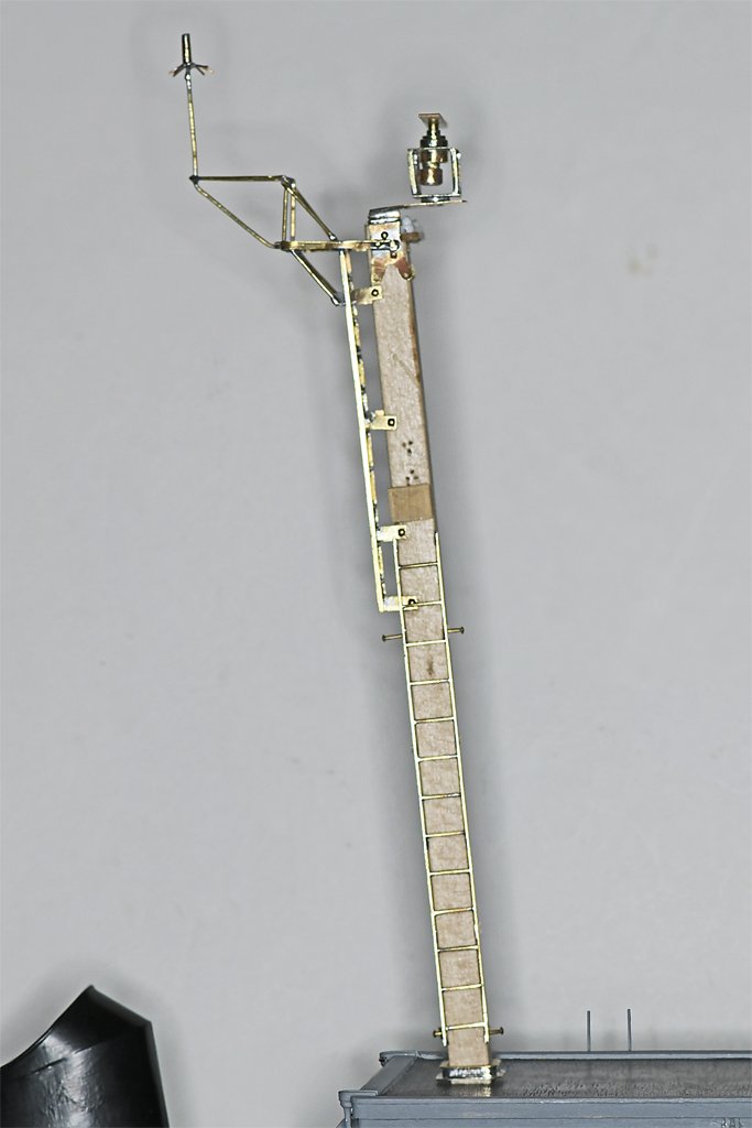
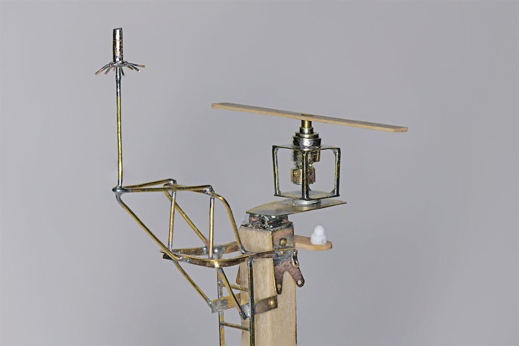
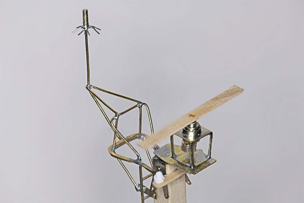
I have been working on the ladders and the mast top details. The upper ladder section on the back side of the mast has been fixed in place. The lower section is temporarily mounted. I thought the mast would be fairly straight forward since I have the blueprints. But when I looked at the photos I took when on board I realized that almost the entire masthead had been rearranged. Originally the AS-390/SRC antenna (left) was attached to the masthead rail, and the radar mounted directly on top of the mast. But a new radar was installed with a longer rotating antenna, so the AS-390/SRC had to be moved farther back. A new frame was made from 1 inch (25.4 mm) inside diameter pipe. It would be 1.24 inch (31.75 mm) outside diameter. At 1:48 this comes out to be 0.026 inch (0.66 mm). I used 0.025 inch brass wire for the frame. The new radar is mounted on a platform that extends forward from the top. I will add two diagonal "pipe" supports running down to the mast. The radar mechanism was housed in a cubical cage. From these photos I see I need to reposition the two after vertical struts to make things "squarer." I needed to mount the radar mechanism before I can permanently mount the lower ladder section. The waveguide for the radar exits to the starboard side and angles down the starboard side of the mast. It then was attached to the forward side ladder supports leading down to a stuffing tube in the O2 deck. I will solder the wave guide to the ladder supports. I don't want to solder it to the supports in place because the heat would burn the wood of the mast. Another surprise I found from the photos is that the yard was half again as long as shown in the blueprints! I wonder what other surprises are in store?
- 496 replies
-
- 11
-
-
-
- minesweeper
- Cape
- (and 1 more)
-
Dr PR reacted to a post in a topic:
USS Constitution by mtbediz - 1:76
-
Dr PR reacted to a post in a topic:
Chaconia by Javelin - 1/100 - RADIO - LPG Tanker
-
I make the mast foot with a square cross section, and it fits into a square socket. This prevents the mast from turning. Then it is unnecessary to glue the mast in place.
-
Dr PR reacted to a post in a topic:
Red Jacket by John Ruy - Marine Model Company - 1/16”=1’ (1/192 scale) - Vintage Solid Hull Clipper Ship Kit
-
Dr PR reacted to a post in a topic:
Billy 1938 by Keith Black - FINISHED - 1:120 Scale - Homemade Sternwheeler
-
Dr PR reacted to a post in a topic:
Muscongus Bay Lobster Smack by JacquesCousteau - Model Shipways - 1:32 - Rescaled and Modified
-
Dr PR reacted to a post in a topic:
La Créole 1827 by archjofo - Scale 1/48 - French corvette
-
Dr PR reacted to a post in a topic:
HM Schooner Ballahoo by georgeband - Caldercraft - Haddock drawings
-
Dr PR reacted to a post in a topic:
Gjøa 1872 by Harvey Golden - Roald Amundsen's Cutter built at Rosedahl, Norway
-
Dr PR reacted to a post in a topic:
Chaconia by Javelin - 1/100 - RADIO - LPG Tanker
-
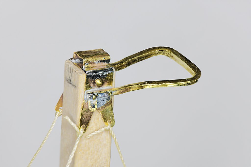
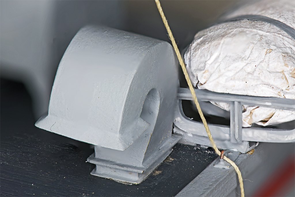
I suspected that I might have to move the vent on the port O1 level because a mast stay would rub against it, and I was right. Four stays support the mast. Two anchor forward on the O2 level and two aft on the O1 level (red arrows). The port aft stay passes very close to the vent Although I think I placed the vent and the stay belaying points where the blueprints showed them, the stay rubbed against the vent. To check the run of the stays I had to make some of the mast fittings where the stays belayed. This was a bit more complicated that I first thought. The mast stay "tang" was part of a more complex assembly with the "masthead rail" that supported an antenna. Additional belaying points for he yard lifts were also included, plus a mount at the mast top for the radar. For this test I tied heavy thread to the stay tangs. I plan to use Beadalon stranded beading wire for the stays - depending upon whether I can solder it or if CA glue will hold it. The stays will have a splice around a shackle at the top, or a special crimped on fitting (the photos appear different from the blueprint). There is an insulator spliced in the middle of the stay. At the bottom end will be a turnbuckle and a shackle to the eye bolt on the deck. Here you can see how close the stay passes to the vent - after the vent was moved. You can see some scratchers in the deck paint where the vent was formerly glued down. In this photo the thread is looped through the eyebolt from the inboard side, pulling the thread closer to the vent. The turnbuckle should pull directly inline with the eyebolt, making a bit more clearance. Even so, the clearance between the stay and the vent will be only about a millimeter (0.040 inch). Now that I have started on the mast I will go ahead and finish it. I have already made the mast collar that fits around the mast at the O2 level.

- 496 replies
-
- 10
-
-
-
- minesweeper
- Cape
- (and 1 more)
-
How about a picture of the vessel (photo, box illustration, drawing) so readers will know what you are building?
-
I used nails on my first kit build because 1) they were supplied with the kit, and 2) the instructions (such as they were) seemed to imply they were necessary. I used small pliers to hold the nails while I drove them in with a small hammer. It was tedious and a lot of nails bent and had to be replaced. In the end I filed off the tops of the nails but they are still visible if you look closely. That was the last time I nailed planks! I think it is a big mistake!! Now I use glue (Duco Cement or Tightbond Original). I heat the planks in place to bend them to fit the curvature and twist of the hull. Then I glue them in place using clamps, rubber bands or whatever to hold them in place while the glue sets. Forget the nails and deep six the nail pusher!
-
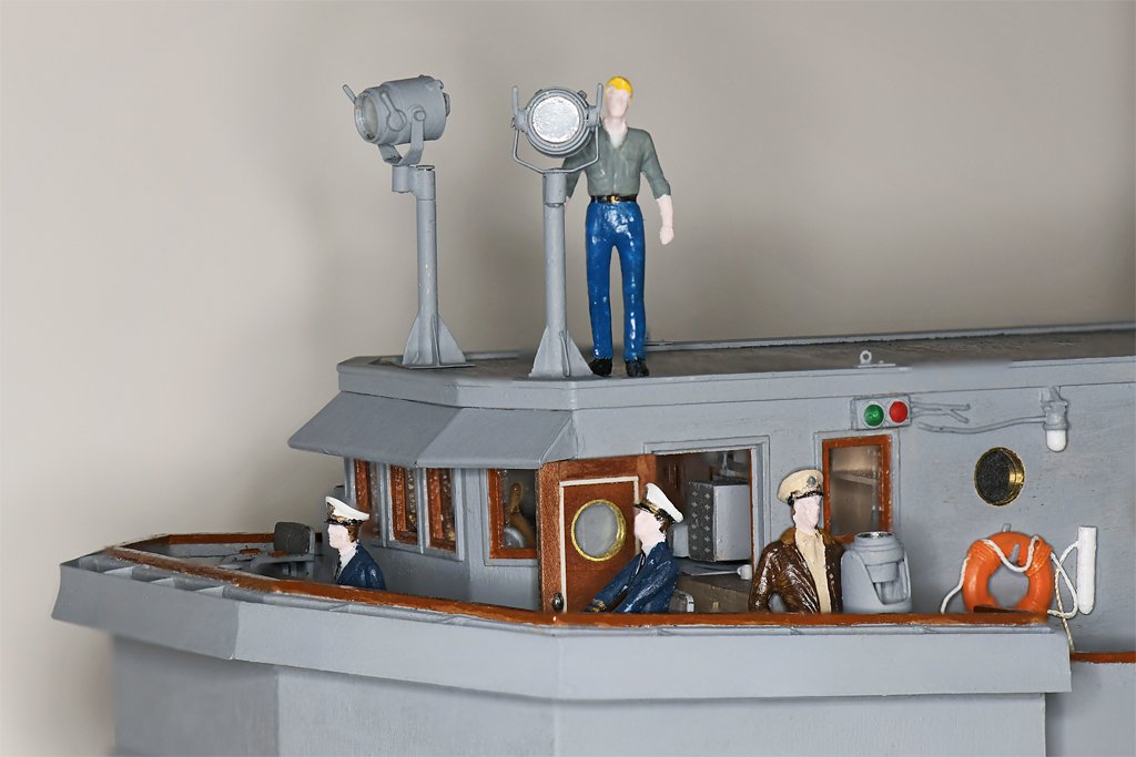
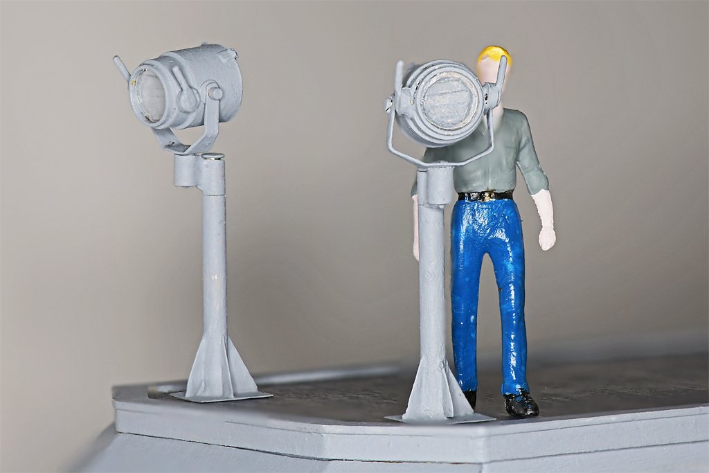
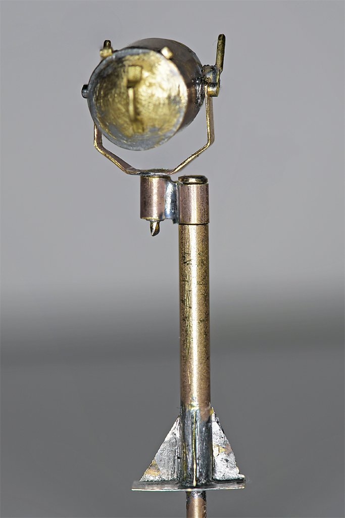
The searchlights are finished - except I forgot to paint the shutter handles black! Now what? The last major details on the O1 and O2 level are the life rails, and then the windows and awning frames over the open bridge. But these will be very delicate so I will save them for last. I think I will work on the mast. It has four stays that fit inside the life rails (they fasten to ring bolts like the one on the O2 level to the right of the sailor by the searchlight). I think one of these after stays may be a problem. It attaches on the O1 level immediately in front of the port life raft cradle. Photos show it just barely clearing the large vent duct forward of the life raft, but it looks to me that it might rub against the duct. I think I mounted the duct in the precise location shown in the blueprints - but the gap between the duct and the stay will be very close. I may need to relocate the duct.
- 496 replies
-
- 9
-
-
- minesweeper
- Cape
- (and 1 more)
-
Great work. It's looking very nice!
-
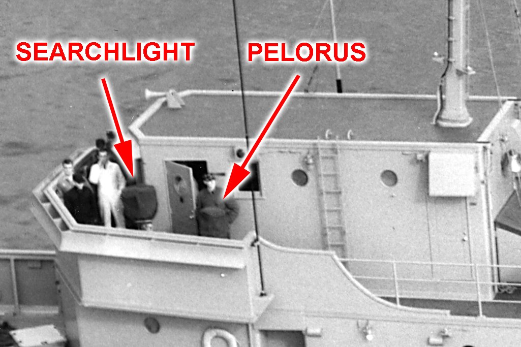
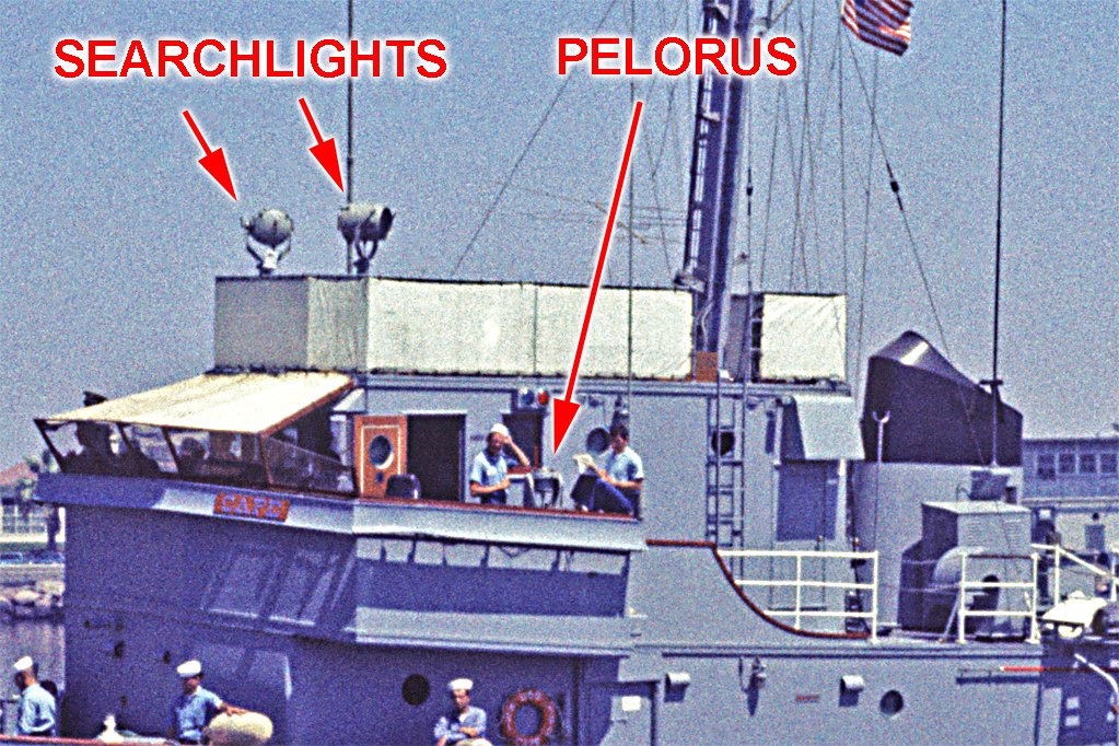
Brian, The photo of the ship in 1959 shows the searchlight with a bag over it. If the light was facing the camera the bag width would be more like the wider mounting than just the front opening. And if the light was sideways to the camera the bag width would be even greater. You can't really say much about the size of the light from the photo. However, the blueprints are unambiguous - it was a standard US Navy 12 inch searchlight (it was the light opening at the front that was 12 inches, not the overall dimensions of the light). I looked at photos of the Cape taken in 1969 and compared the diameter of the light opening to other things of known width, The light opening comes out to about 12 inches. So I am pretty sure they were the original lights that had been moved. Furthermore, these were off-the-shelf searchlights dating from WWII or before, and the same things were used on just about all US Navy ships. I have photos of the lights on the USS Oklahoma City CLG-5 taken in the early 1970s and they are identical to the lights on the Cape. I wouldn't be surprised if the Navy is still using the same thing!
- 496 replies
-
- 3
-
-
- minesweeper
- Cape
- (and 1 more)
-
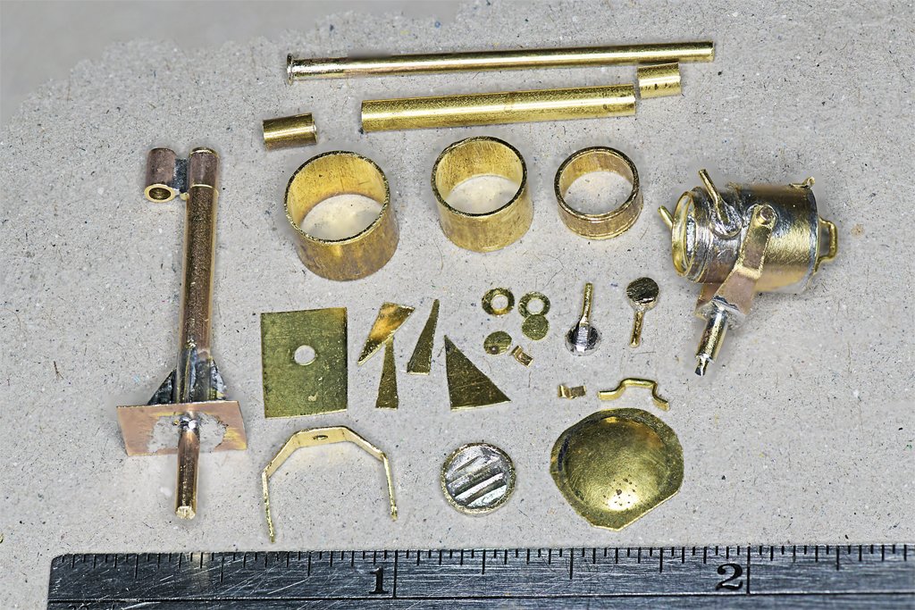
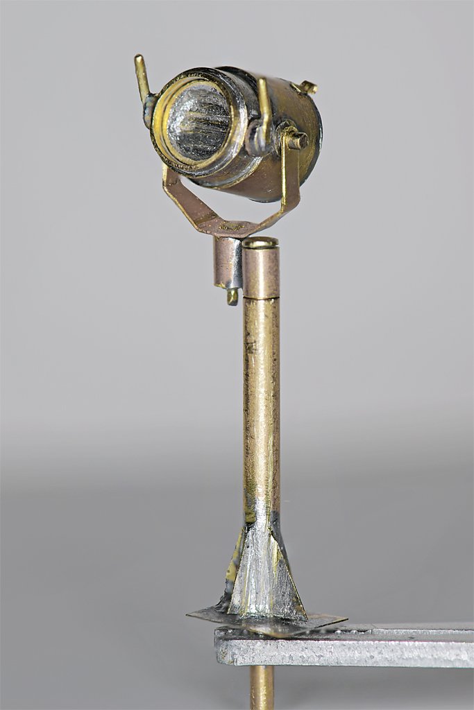
SEARCHLIGHTS One of the challenging things about modeling ships is trying to keep up with changes that were introduced over the life of the vessel. There were a lot of changes on the Cape over the years. The position of the searchlights was one of those changes. When the ship was commissioned in 1959 (left above) the searchlights were mounted on the open wings of the bridge. But by 1969 (right above) the searchlights had been moved to the O2 level above the pilot house. This freed up room on the bridge wing and placed the searchlights higher where they would be more effective. You can see a lot of other changes that had occurred during the 10 year period when the Cape was in service. The Cape had a number of modifications that never made it to the USS Cove MSI-1. The searchlights were never moved to the O2 level on the Cove. Notice that the vertical ladder from O1 to O2 level was moved aft on the Cape, and the life rails on the O2 level were different than on the Cove. The whistle was moved from the O2 level directly over the open bridge (where it would have been annoyingly loud) to a higher position on the mast. A voice tube was added on the O2 level to communicate with the helm. This is a kit of parts for one 1:48 scale 12 inch (305 mm) searchlight, flanked by pieces of another assembled unit. The hardest part of the assembly was the base, where soldering each of the four support pieces to the tube and base plate risked unsoldering all the rest. The largest brass tube is 5/16 inch (7.9 mm) OD and the third (inner) tube is 1/4 inch (6.4 mm) OD, or 12 inches at 1:48 scale. Most of the flat parts are 0.005 inch (0.13 mm) brass sheet, but the yoke was made from 0.010 inch (0.25 mm) brass. Most of it is soldered together, but I did use CA gel in a couple of places. The shutter assembly (lower center) was a bit tricky. Six narrow strips of 0.005 inch brass were overlapped and soldered to the back of a thin ring cut from a 7/32 inch (5.6 mm) tube. Here are some photos of the complete assembly. After it is painted I will put a circle of clear styrene in front of the shutters. The parts rotate around the offset vertical mount in two places, and the light rotates around the horizontal axis. The assembly is 1.375 inches (35 mm) high, or 5' 6" (1.7 meters) high in 1:1 scale.
- 496 replies
-
- 15
-
-
-
- minesweeper
- Cape
- (and 1 more)
-
Thanks everyone! I am working on the searchlights for the O2 level - photos soon.
- 496 replies
-
- 5
-
-
- minesweeper
- Cape
- (and 1 more)
-
There are MANY versions of the DXF file format. Different programs use different versions, and many are not back compatible to older versions. Sometimes companies would introduce a new version that was deliberately incompatible with other software, to prevent users from switching to the other programs and taking their work with them. I haven't used DXF format for many years, but way back when version 13 was the most commonly used version, even after several newer backward incompatible versions were introduced.
-
It is a beautiful ship. Enjoy the build!
