


rcweir
-
Posts
185 -
Joined
-
Last visited
Content Type
Profiles
Forums
Gallery
Events
Everything posted by rcweir
-
 For 1:50 and 1:72, Kolderstok Models has just released a line of 17th century Dutch sailors. https://kolderstok.com/en/collections/miniaturen-kopie And I just found out today that CAF Models includes 10 1:50 gun crew figures in their "La Renommee Section" kit. Depending on how desperate you are, the quite modest price of the kit might be worth it just for the figures (though the whole kit looks great). https://cafmodel.com/product/la-renommee-section/
 -
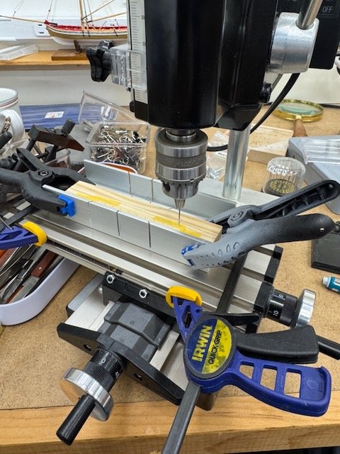
No one has mentioned the Vanda-Lay milling machine/drill press which is sold by a sponsor to MSW - https://www.vanda-layindustries.com. By default the machine is powered by a Dremel, but I've gotten the Foredom attachment and that's the prime mover in mine. I have been quite happy with the quality of my machine including the finish and precision of its parts (all machined aluminum). The caveat is that I have very (very) little working experience to bring to this discussion, but the machine isn't a toy and the support is great (they're built and sold by a gentleman in California). For price competitiveness, I can't say much - you can look at their prices and decide for yourself. I don't have the drill press conversion (and don't need a 3rd drill press). The table is set up as wefalck described earlier: "... tables are typically replaced by 'tool-plates', i.e. slabs of steel or aluminum with patterns of threaded holes for various types of fasteners". In this case the holes in the table are tapped for 8-32 thread screws. It took me a long time get past the mental block of no T-slotted table, but once I adjusted my thinking, I believe things will be fine. My one real exercise so far, which was to mill away some material on the sternpost of my Statenjacht model, went fine. I can send more details if requested. I don't seem to have any photos of the current setup, but I could provide that, too, if there's interest. Bob
-
I second that emotion! Bookfinder is great and where I always go for anything other than new-on-the-shelf copies. In many cases it is a good idea to use the broadest search criteria you have patience for, because the underlying booksellers' titles are often incomplete, or lacking an author's name. Prices shown by Bookfinder are in US dollars (for me in the US, at least) and include shipping costs. That makes it easy to make true cost comparisons. They also show you who the actual provider is, so you can favor (or disfavor) particular vendors if you wish. I've ordered dozens of books through their listings over the years.
-
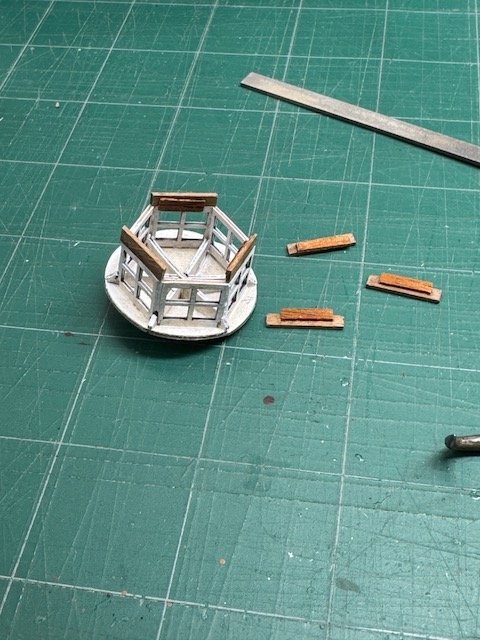
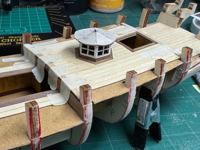
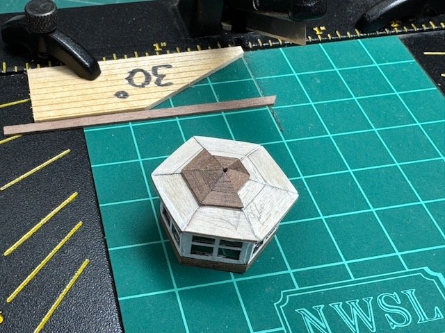
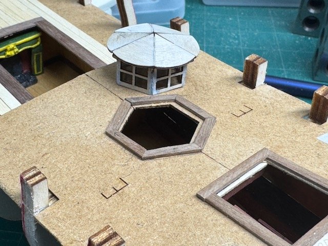
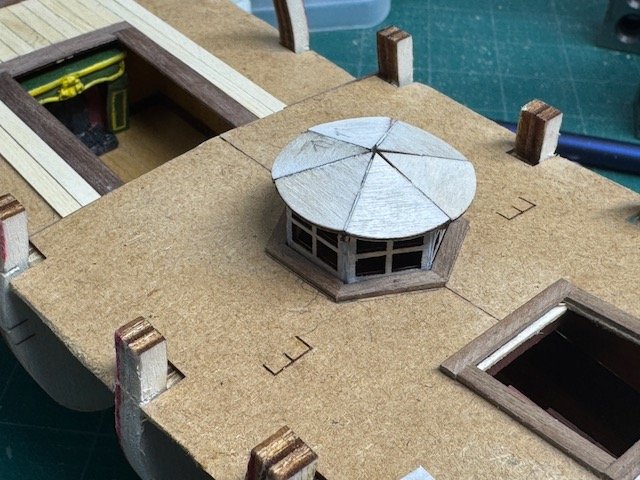
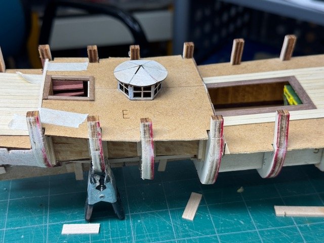
Here's a short update on my progress. First is where I am on the little hexagonal cupola. I've added the walnut skirt around its base. The way I've handled the base is not exactly as it is in the instructions, but the ideas are the same, I think. Besides having the structure look good, I want to make sure that its removability is discreet, i.e. that the viewer can't tell that it lifts off. (Because it might not - I'm still undecided as to whether I'll glue it down or not.) After getting the base all set, what I'm working on now is the walnut roof. The kit-provided subroof is very helpful in getting a good finish layer installed. As you can see, the leaves of the subroof are rounded, which visually makes a somewhat saggy-looking circle when its all installed. Some of the build logs keep the rounded edges, but the photos in the instructions square them off, so that the top's hexagonal like the rest of the structure. I like that look better, so it's what I am doing. You can see in the next photo how that's looking now, with the walnut topping incomplete. The last couple of photos show the expensive Turkish carpets I've gotten for the lower cabins. Eventually the furniture will be painted and permanently installed, but I'm putting that off until after the planking. Pancakes are calling me now, and I have to go. Thanks for looking in! Bob
-
You're doing a wonderful job on Gretel, and I think those sails look amazing! I have received information to believe that a Gretel kit will be dropping down my chimney at the end of the year, so I'm happy to be able to learn from your excellent efforts. Bob
-
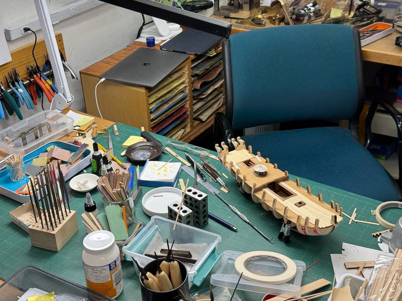
Work area pictures only
rcweir replied to Johnny Mike's topic in Modeling tools and Workshop Equipment
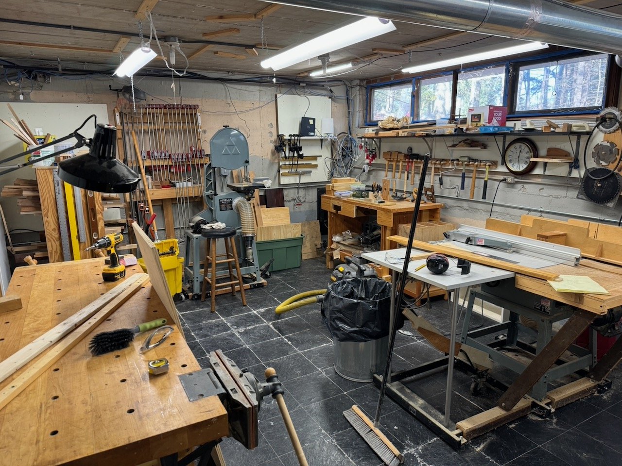
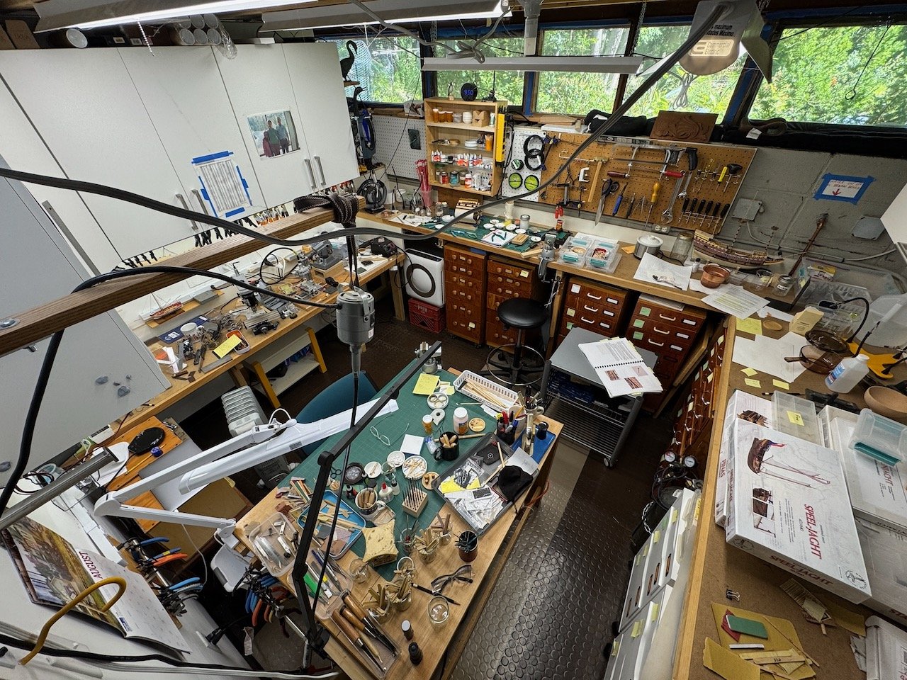
This is my basement hideout. The first two are of the cubicle where I do most of the modoeling. I carved this out of the big workshop when I gave up making furniture. The second two show the rump big workshop, now minus some of the big tools, but the tablesaw still gets plenty of use, as does the bench. Plus, I have my collection of Byrnes machines out there. Many happy hours spent down there. And more to come as I approach full retirement! Bob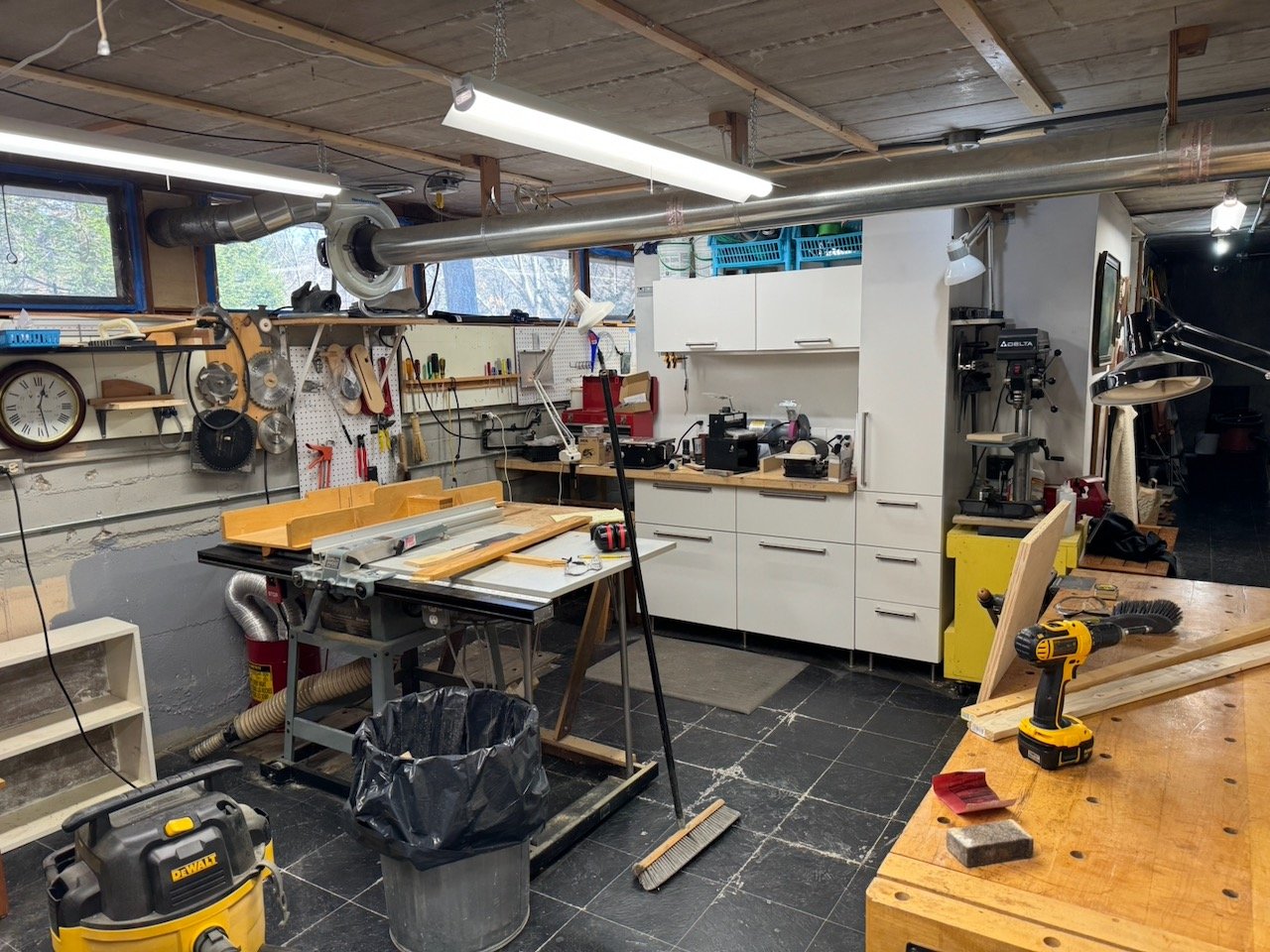
- 52 replies
-
- 18
-

-

-
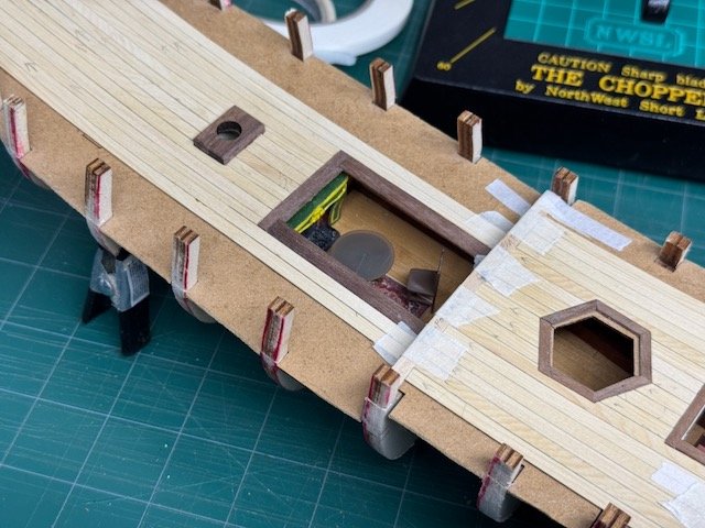
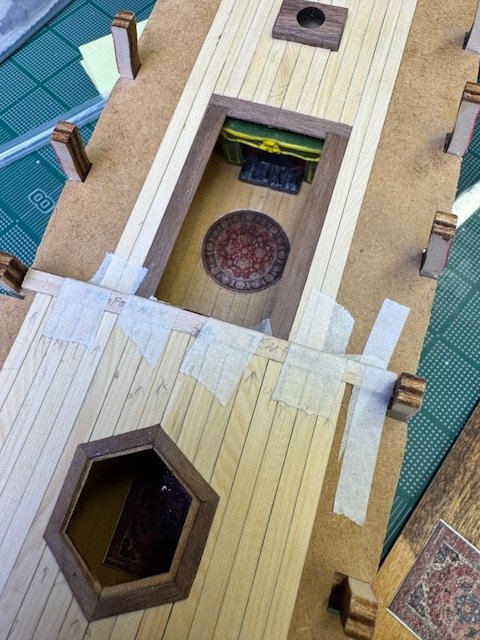
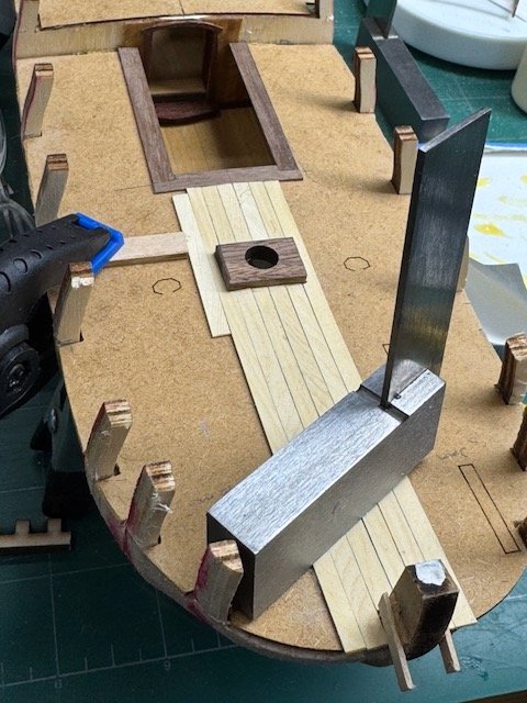
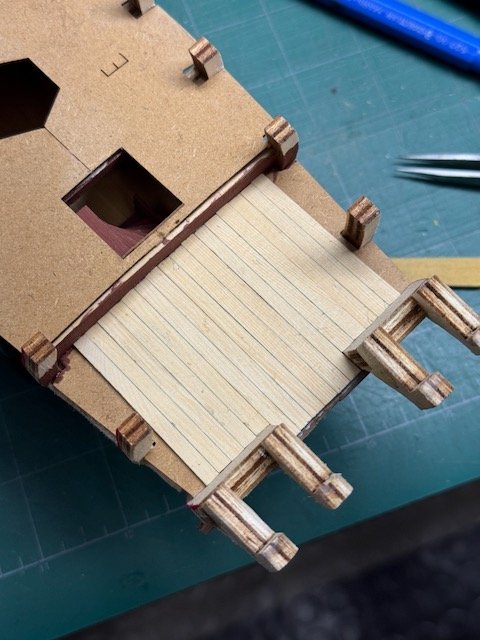
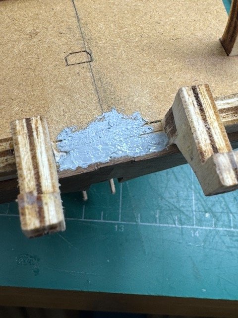
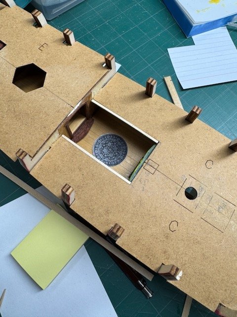
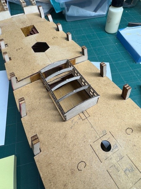
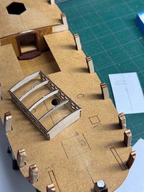
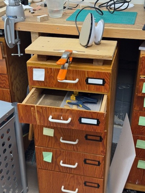
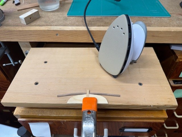
A lot has happened since my last report. To start off, I've started planking the decks. I'm using Alaska yellow cedar for most of the deck. The kit supplied basswood is fine - all of the supplied wood looks great - but I think AYC will look a little better, and to be honest I wanted to mill this myself (from stock I had on hand) just for the exercise. A question I'm working out as I go along is is how much of the deck trim details, e.g. combings, borders around the deck houses, etc. I'll highlight with walnut. On a typical model I wouldn't do this, but it seems appropriate for a showboat kind of vessel. I started on the aft most deck (which will be almost totally obscured when the big after deckhouse gets added). First I levelled the area where the tiller enters, and then planked out to the stanchions. On all of these decks, the outer part obstructed by the stanchions will remain unplanked for now. Speaking of milling, I've been trying to develop safe and effective practices on the little Byrnes saw that let me mill strips that are consistently the right size and where I have confidence I'll finish the job with the same inventory of fingers as I started. Principles (and hazards) don't really change from the big tablesaw, but for me the big-saw jigs and practices I'm used to don't directly scale down. So working out safe, effective, practical and efficient techniques is an important goal. Back to deck planking. I constructed the frame of the midships deckhouse earlier than called for so I could see exactly how it was going to fit on deck. As the instructions note, the subdeck opening down into the midships cabin is a tad wider than the cabin structure, so some support has to be provided for it. Also, the deckhouse top piece will be removable, so I've made a supporting surface (of walnut) that will eventually have a rabbet to register the deckhouse's position to prevent it from sliding around in heavy seas. Visually, it will look like a baseboard around the cabin. I've also assembled the little hexagonal cupola that looks down into the after lower deck cabin. Assembling that piece would have been pretty easy had I only followed the guidance in the instructions. They say to assemble the rafters first, and then attach the windows. Which makes great sense. What I did was to first arrange the windows in a hexagon, fit the rafters on to them, then glue it all up. My way did work, but it required a lot more cuss words than would have been needed doing it the right way. I sometimes wander down rabbit holes trying to decide about small details, and in that vein I've been looking at the two small hatches that are forward of the deckhouse. The kit photos show the forward hatch cover as having what look like a couple of straps for lifting, and the after (slightly larger) one has hinges and a ringbolt. Both of those hatches sit over their coamings, rather than sitting in a rabbet in the coaming. In trying to decide the details of exactly what they ought to look like on my model, I studied drawings from Hoving & Emke's "17th Century Dutch Merchant Ships Plans Set for modelers". That publication has drawings for numerous vessels of widely varying size from the statenjacht's period. And, most of them smaller than a pinas have hatches similar to those on this kit. Thanks to those detailed drawings I can see, indeed, that it was common for hatches on smaller vessels to enclose the coamings. Those hatch covers didn't rise very far above the deck - looks like no more than 2-3" (I haven't tried to measure it yet). None of the Hoving/Emke drawings showed hinges, though maybe they were sometimes present in real life. But several of those hatches had a pair of cone-like features, and I wondered what they were. After much digging through my references, I found the explanation by Ab Hoving in "Dutch 17th Century Ship Models in Paper". On p. 43 there is a photo whose caption describes it as "Hatch for the cable tier". In accompanying text on that same page, he says,"The hatch for the cable tier has covers on both sides over the holes where the anchor cable passes". And then "The small hatches entering the spaces below decks can simply be cut from 1mm card. If you like, you can glue coamings around them, But on board this simple ship most hatches fit over the coamings, which means that they are not visible, unless you want to show the hatch in open condition." I intend to follow Hoving's guidance on how to do my hatches. Mine won't open - there's nothing to see below decks there. This is a poor sketch of what I'm talking about... Other odds and ends... I always have trouble finding bench space when I need to start bending planks, so I built a little platform for the purpose on one of my roll-around tool cabinets. With this setup, plank bending is ready to go anytime, but won't be in the way when not needed. The stem, sternpost and keel are all very nice laser-cut walnut pieces which I will probably attach before starting to plank. In preparation for gluing them on, I've put temporary tabs on the false keel to make it easy to keep those pieces centered. I used this same system when attaching the transom, so I could ensure that the sternpost position on it was properly aligned with the false keel. I don't have any pictures of fitting the transom, unfortunately. But in the photo below you can see where I had the temporary alignment tabs. Before installing the transom, I fitted the sternpost because fitting's a finicky process and easier to work flat on the bench. But I didn't glue it on. Then, when installing the transom, the sternpost had to be temporarily involved again in making sure the transom position was correct. The tabs helped make that a relatively easy process. The deck stanchions at the tops of bulkheads will eventually be cut away, after the outer hull is planked. So I sawed all of them 1/3-1/2 way through on the outboard side, while it's very easy to do. I hope I left enough meat so they don't break during the planking process. Thanks for looking in. Bob
-
The kit's is more intricate, but your carving looks mighty good. Especially since this is an imaginary vessel, and the embellishments can be whatever you please, I think that pushes the balance even more in favor of your own handwork.
-
It's been a while since the last post - I've been working away and it's hard to break away from that long enough to put together the post. This post is about work on the two lower deck cabins. But first, I want to draw the attention of future builders to an important structural detail that is easy to overlook. Discussion of the interior cabins is mostly on pp 2-7 of the instructions, and culminates (almost) with the installation of the spiral staircase. But later, on page 10, there is mention of "a small part" from the 3mm plywood laser cut sheet that goes onto bulkhead 10. That small part is actually labelled 10, and it's important - it's the aftmost support for deck E (which covers the after cabin). Since this part 10 is half the thickness of bulkhead 10, that allows the after portion of bulkhead 10 to serve as the forward support for deck D. So, remember these two points: (a) you ought not to finish the after bulkhead of the cabin until this extra part 10 is installed and (b) the height of that piece assumes that it's sitting on top of about 2mm of deck D subdeck and planking. In some of the pictures that follow you'll see that I learned these lessons a little late. My installation of part 10 is in the middle of the photo below. First step was to build the spiral staircase, which is a little marvel of a minikit. I was careful to ensure the first two sides were absolutely square to each other, and from that point everything basically jumped into place. Once complete, put it aside in a safe place because it won't be needed for a while. I opted to paint mine (AK Interactive's mahogany brown), but if you are intending to stain it then it's probably a good idea to clean the char from the tread edges a little more thoroughly than I did. The interior rooms can, in theory, be viewed in the finished model by removing covering upperworks, but I'm deeply skeptical that will ever happen with mine once it's done. Nonetheless I couldn't restrain myself from putting effort into making both spaces presentable, particularly the forward cabin that has the fireplace. I decked the cabins with boxwood that I had on hand, panelled them with satinwood veneer, and used mahogany veneer (most of it highly figured) for baseboards, benches, door frame, etc. I wanted to hang pictures on the after bulkhead flanking the doorway passage, but that can't work because the upper deck bisects all but the passageway. Working with the veneer was interesting. I have a huge quantity (in modeling terms) left over from my furniture building days. I didn't worry very much about precise fitting, knowing visibility would always be restricted, which is why the after cabin, especially, looks sloppy in the pictures. In the forward cabin I was more careful about fit and detail. I did consider making a door between the spaces, but didn't. I did, however, try to make the step down into the cabin and the door frame suitably elaborate for the kind of space it would have been on the real ship. The picture below is out of sequence since it shows the spaces after I applied the Watco Danish Oil. This is my first experience with it, and I'm quite happy with the result. My paint scheme for the fireplace was inspired by looking at photos of the Utrecht (a reconstruction of an 18th century statenjacht). On the exterior of those spaces - particularly the after cabin - I added a lot of bracing for the veneers to make sure they'll stay in place over the coming centuries. I glued the staircase in place in accordance with the instructions, using the deck E subdeck as a guide. Looking at the pictures after installing the subdeck, it's clear that the after wall of that staircase ought to be finished the same as the after bulkhead. I may add some satinwood veneer to remedy that. Oh, I should mention that on all the frame members I painted an area around the middle with white and then carefully marked that frame's centerline. Those marks are useful for aligning things, especially the two-part subdecks, C and E. After installing the staircase I made the sequencing mistakes warned against at the start of this post. What I did was the following: veneered the after bulkhead; realized that the extra part 10 existed, and installed it on top of frame 10; realized that part 10 was supposed to sit on top of subdeck D and its planking; so I then added a 2mm top to my part 10 so that top deck, when laid, will have the proper sheer. I also had to scrape off the now too-short veneer I'd applied to the after bulhead of the interior cabin. I redid that veneer before gluing down subdeck E. I hope there will not be further repercussions from that misstep. I purchased some scale furniture that I was going to put in the forward cabin. I may still do that, and I plan to put some furniture in the big upper deck cabin, too. The next several photos are included to provide views of what can actually be seen of those compartments, in the best case of visibility, after the upper decks are installed. It's not much. That's all for now. Next up will be exterior work leading up to planking. Thanks for looking in, Bob


-
You're doing a great job, Olli. I was unaware of the Gretel kit before you started your log, but now I think that this is one I have to build, too. It's a good scale , looks like a fun build, and it will be wonderful to have a model on my shelf based on af Chapman plans. Bob
-
I'm overdue for an update, but there hasn't been a good point to pause. Since the last posting, I've mostly been shifting between work on the transom and fitting out the two lower deck cabins. This post is about work on the transom. The first task was to glue four brackets at the top of the lower transom that will eventually support the upper one. Gluing the brackets into position was challenging because there's there's not nothing to hold them in position, and they aren't balanced to just sit in position. But they have to be located perfectly to support the upper transom (which can help with alignment, but isn't being glued on yet). After a lot of thought, I did the following: tacked the lower transom onto a block of mdf for weight and stability and because the bracket arms are just a wee bit longer than the transom is deep - which is why they hang over the edge of the mdf in the picture below. Then I glued little sacrificial arms on to the bottom of the brackets so that I could adjust and hold each in position as the glue (Titebond) dried. With the brackets and transom stable, I could use the upper transom to tweak the brackets after applying glue. I did the glue up in two steps - first the inner pair and then the outer. You'll see in the photo above that the slots in the upper transom for the outer two brackets are far from square to the brackets, but I've checked photos in the instructions and several build logs, and that's just the way it is. After the glue dried it was trivial to chisel off the basswood brackets. Once the brackets were on I applied the diagonal walnut planking and then the wale that is above that planking. (That wale is supposed to be 2 planks thick - I haven't made the upper half yet). To help me with the planking alignment, I glued a couple of bassword guides which were later removed. I have installed that transom, but not until later.


-
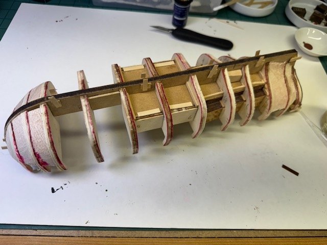
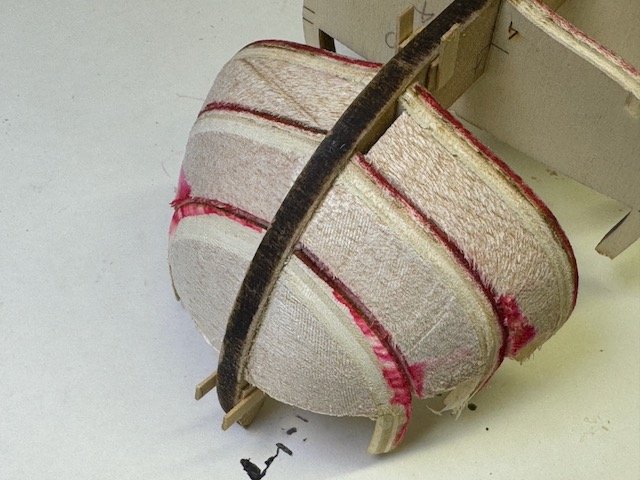
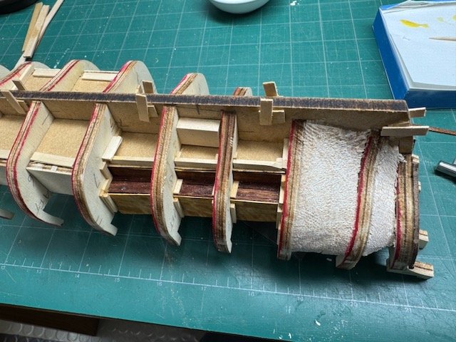
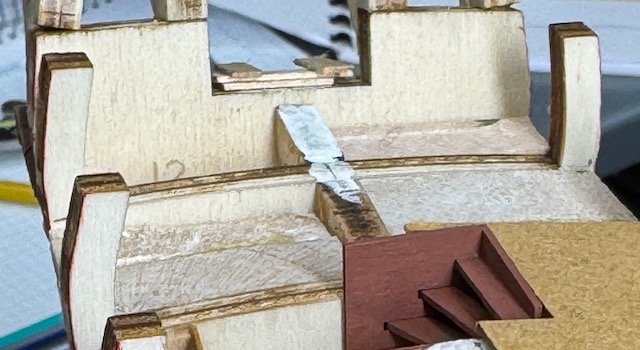
I'm hopping around on the model right now; there are a number of isolated tasks whose order doesn't depend on each other. This post is only about the start of fairing the hull, i.e. the bow and forward four bulkheads. I found the instructions and the various web logs ambiguous on exactly how the area right at the bow ought to be prepared, yet it's absolutely critical to the planking that one gets this right. Or so I believe right now. The instructions discuss fairing and planking later than I am in the work, but I decided to start early to minimize the possibility of banging something else up with all the rough handling that the hull is sure to get. Instructions call for balsa filler only right at the bow, forward of bulkhead #1. But, after studying other logs, I decided to put in balsa starting at bulkhead #3. I also put in some aft, between frames #10 and #11, but that's probably not necessary - what I really meant to do (and have now done) is to add balsa aft of #11, between it and the not-yet-installed transom #12. I also decided to add temporary stiffeners on the bulwark ears of bulkheads #1, 2, 3 and 11. It will be easy to remove them later, and those ears get their share of stresses during the fairing. All of the fairing work I've done so far involves only the area between the bow and bulkhead #4. The stern can't be done until bulkhead #12 is installed. And the midships in between ought to be simple and straightforward. One caveat which I hope is obvious: it's not a given that the way I'm going about this is the "right" way. Time will tell. The next several photos are pretty repetitive, but I want to give future builders of this kit clear visual information about how I'm going about it. My plan is to leave space for a ~1.6mm rabbet (i.e. the plank thickness). On top of the 6.5mm false keel in the pictures will be attached an 8.3 mm walnut keel. I am undecided as to whether the keel ought to be attached before I start planking, or not. The instructions don't do so, but at least one build log (a good one) does. Nobody talks specifically about the rabbet, and the discussions usually go no farther than to make general statements about the shape being tough to plank. Here are my photos showing how I've done the fairing. In this last photo I'm holding a plank to show how it sits against the false keel. My tools for the fairing shown, incidentally, are all rasps. The red lines on the bulkheads are to make it clear when I'm sawing away where the margins are. That's enough for now. I'm also actively working on planking the transform (bulkhead #12) as well as fitting out the interior cabins. Thanks for looking, Bob


-
I've made some progress over the past three days. The first three pictures are part of my "unboxing" images that I missed the first time around - they're the resin castings and a set of laser cut decorations. The castings don't photograph well, but I think they'll look great all painted up. I also think it will be a challenge to figure out where they all go. The first real work is to assemble the frames (all but the last one, #12). Which is done in the usual way. For the first time I used lego blocks to help ensure the frames were square to the keel. After the frames (probably I should call them bulkheads) are glued in, subdecks for two cabins are added. The cabin rooms will be visible to some degree, so the spaces need to be planked, at least. Plus there's a fancy fireplace in the casting set for the forward room. Since I have a supply of fancy veneers on hand, I'm thinking I will try to use some of fitting out those rooms. Fancy a deck of curly mahogany with satinwood wall panelling? At any rate, while I'm not sure any of this will ever be seen again, I do intend to try to make those rooms look good. Most of the edges of those decks aren't well supported, so I added stiffeners around the perimeters to all the places where it was missing. I also put in stiffeners on the false keel between frames 4 & 5 and 8 & 9 because that's where the fastening screws are ultimately going to go when I mount the model on a display base. You can see them in the photo above. The stiffeners between 4 & 5 also serve to enclose the mast step, which is called for in the instructions. That's all for now. The next posting is going to be just about fairing the hull, but I don't have time right this minute to concentrate on the writeup (I can smell the pork chops, and they're almost ready!) Thanks for looking, Bob


-
I'm especially excited about building this kit: since I was a kid I've dreamed of making models of two 17th Dutch vessels: a statenjacht and a fluyt. Thanks to Kolderstok, those dreams now have a realistic chance of becoming reality. This statenjacht kit is the first step and it's gotten off to a good start this weekend. There are several build logs available, and they will help guide me: on MSW, there's Melissa T.'s nice build - And there's an excellent, highly detailed log on the Dutch forum by pietsan. The logs are very helpful - the kit instructions tend to be on the terse side - so the logs help to illuminate the inevitable questions about what goes where, when. The kit comes with sails, which I plan to use, and a large array of resin castings. I got my kit in 2019 (an Xmas gift from the admiral). Kolderstok subsequently upgraded those castings and *Hans* (the owner of Kolderstok and designer of this kit) graciously sent me all the upgraded fittings. (So I've been rewarded for dilly dallying for 6 years.) Here are some photos of what came with the kit. Not shown are the upgraded castings (I'll try to get them into the next post), the nice oak display stand (available as an extra), and the paint set. I used Kolderstok's paint on the Pinas build, and liked them: they're good colors and apply nicely. My next post will show the work that's underway now. Thanks for looking, Bob


-
Well, the model is finished now. I post the pics here as evidence, and will also make an album in the gallery shortly. This was a fun kit to build, with plenty of opportunities to customize details. One regret is that I couldn't find 17th century figures in the right scale to add more life to the display. Next up for me is another Kolderstok kit, their 17th century Dutch Statenjacht. I'll start a log at MSW on that one soon. Thanks for following along, Bob


- 76 replies
-
- 10
-
-
-

-
- Pinas
- kolderstok
- (and 2 more)
-
This is a short post about the display case. Once I finished the chains I turned my attention to something I ought to have thought through much earlier, i.e. what kind of display base to make and how would I mount the model to it. An open model like this presents a challenge - what hardware can you use that will be invisible, yet fasten the model securely to its base? I did not answer that question for this project - I think I'm going to end up with nothing better than glue (probably epoxy). Right now the model is essentially just sitting, almost loosely, on two brass pegs. (I have no photos of those pegs.) Aside from the fastener question, though, I'm happy with the rest of the display case work. I decided not to have a professional make my acrylic cover; instead I followed guidance in an excellent article I found on the web titled "Make a Museum Quality Acrylic Display Box" (https://www.instructables.com/Make-a-Museum-Quality-Acrylic-Display-Box/). Mine didn't come out museum quality, but the article isn't to blame at all, and I learned some very useful tips. This method requires a full size tablesaw and a router table, both of which I have. Here are just a few photos of what I used and my setup. The last two photos illustrate a big lesson for me: I'm using the table saw fence to guide the sheet of acrylic - the fence around the router is merely serving as a dust collector. Doing it this way (which requires that opposite sides of the piece are parallel) avoids bumps as the work piece is slid past the cutter. The end result of my case efforts looks like this: It's a lot of work and can be messy without good dust collection. But mistakes can be buffed away into invisibility, and it's more fun than driving to Malden and paying $2-300 for a custom cover. The wooden base is walnut (from scraps I had lying around). Construction was simple. I first cut a rabbet around the four sides, and then attached 3/4" x 3/8" strips around the perimeter onto which I routed a nice molding. I very rarely use the router, and you can see my inexperience in the next pictures. I ought to have provided support on the leading edge of the feed; something I realized a little too late. So, two corners were somewhat chewed up. But, happily both were easily and invisibly repaired with Titebond and walnut dust. (And, after all, this makes no claim to be "fine furniture".) The final result is this: My next post - the final one - will be the "graduation" photos. Thanks for looking! Bob


- 76 replies
-
- 7
-
-
-
- Pinas
- kolderstok
- (and 2 more)
-
A long time has elapsed since my last post. One reason for the delay is that I had a long, an ultimately only marginally successful, battle making the chains. The long and the short of it is that I couldn't come up with a way to make them that I thought looked good. I tried a number of ways, but never did really figure it out. This is important to me not only for this model, but the next one up (Kolderstok statenjacht) has a very similar set up to this one (same period and same scale). But, at least now I'm forewarned and I've had some practice. I think a method such as Chuck showed recently on his Speedwell log might work for me. Anyhow, enough whining (for now!) The first picture shows my original attempt. My objections to this, not all clearly visible in the photo, are (a) the fact that the two long bars under the channel aren't anywhere near parallel or uniform, (b) there's a wire twist under the bolt in the wale which really thickens things there, and (c) the wire twist under the deadeye that's submerged in the channel is too fat for me to install a batten over it. At this point I stopped work for 6 weeks, did other things, thought about the chains, and ran some experiments. In the photo above, each chain assembly uses a single piece of wire (about 23 gauge). What I replaced that with uses three pieces of wire. The section below the channel is a single link, as shown in the next photo. That solved the problem of having the two bars parallel. Around the deadeye I wrapped two wires: a length of 26 gauge (which is never really seen) and a length of 23 gauge on top of it. The fat outer wire is the strap around the deadeye that one sees. It's twisted once and clipped, and acts as a stem to keep the deadeye upright. I hate that twist, and for the next model I intend to find a way to eliminate it. The small wire is also discretely twisted and one arm clipped. The one remaining arm of 26 gauge connects the link below to the upper assembly. Everything is black, so the mess of wires and twists isn't very visible at all. And, what matters most to me, those long bars are parallel and look reasonably uniform from one chain to the next. My next post will be soon - the chainplates were the last substantial work to finish the model and it's actually all done now. Thanks for looking, Bob


- 76 replies
-
- 9
-
-
- Pinas
- kolderstok
- (and 2 more)
-
Worst Planking Job Ever
rcweir replied to rhephner's topic in Building, Framing, Planking and plating a ships hull and deck
Looks like quite a respectable job to me. You've made great strides from the first effort. Well done! -
There are dust collectors like this Dewalt: https://www.amazon.com/gp/product/B0BGBM3QFX/ref=ox_sc_saved_image_3?smid=ATVPDKIKX0DER&psc=1 I've been eyeing that one for some time. One caution if you go this route is be very sure that the appropriate replacement filters are available. There are cheaper no-name units also available on Amazon, but getting filters for them appears to be difficult to impossible. Bob
-
Great job ECK, as always, and thanks for the comparison photos! It's an eye opener to see these ships side-by-side. With your collection of high-quality builds it would be wonderful, though undoubtedly a lot of effort for you, to make a photo shoot of everything together that you have in 1:64. Perhaps you could even think about making a big diorama in your garage! (Just kidding!) But Victory will make an excellent flagship for that fleet.
- 52 replies
-
- 1
-
-
- Grecian
- Vanguard Models
- (and 1 more)
-
Log to PDF Tool
rcweir replied to VTHokiEE's topic in Using the MSW forum - **NO MODELING CONTENT IN THIS SUB-FORUM**
This is really wonderful! I followed the macos instructions and heeded Tossedman's info that apple silicon was required. It went smooth as silk, and I now have a pdf that I really want to keep as a searchable reference. Thanks so much for making it not only possible, but easy. Bob -
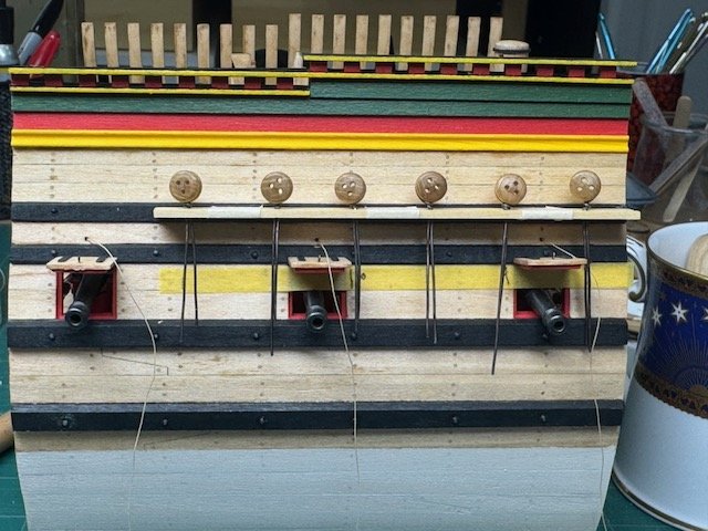
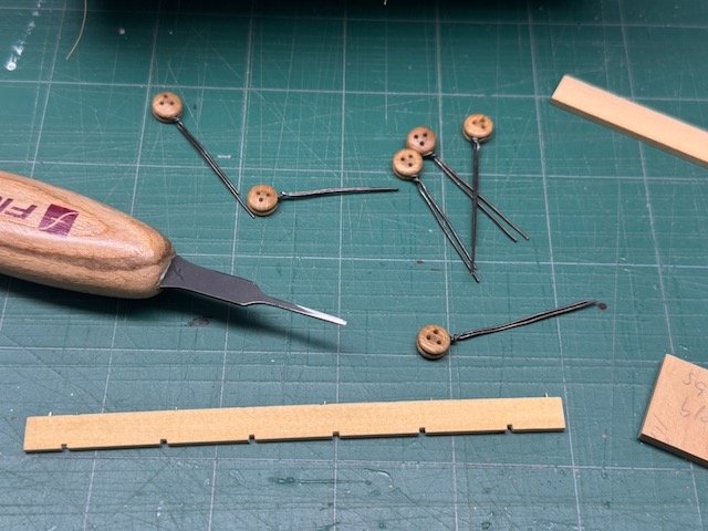
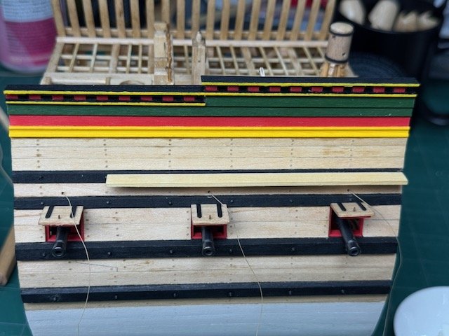
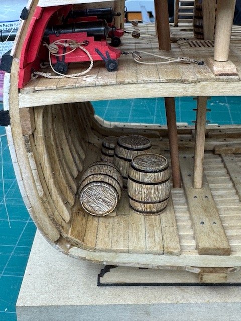
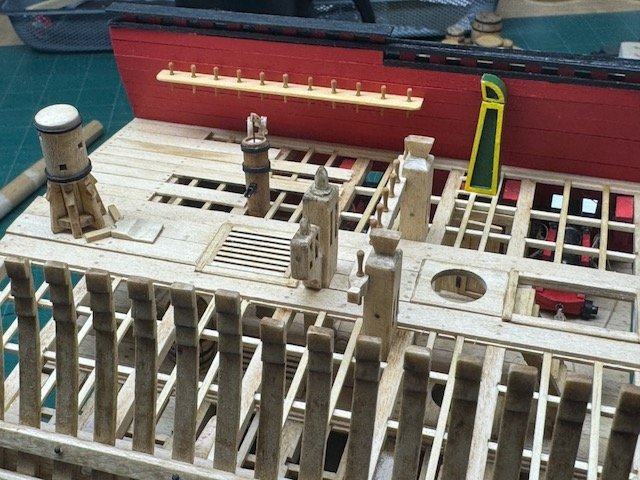
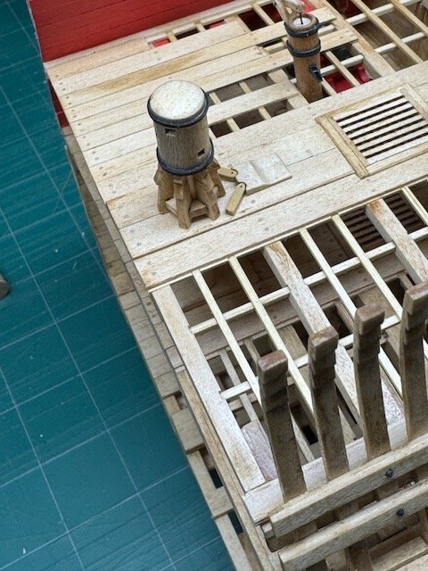
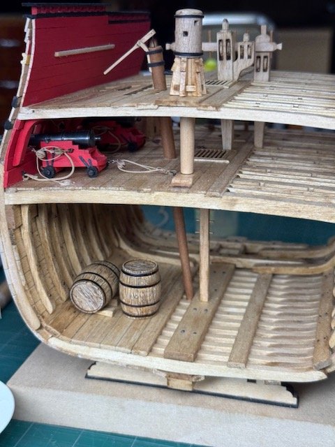
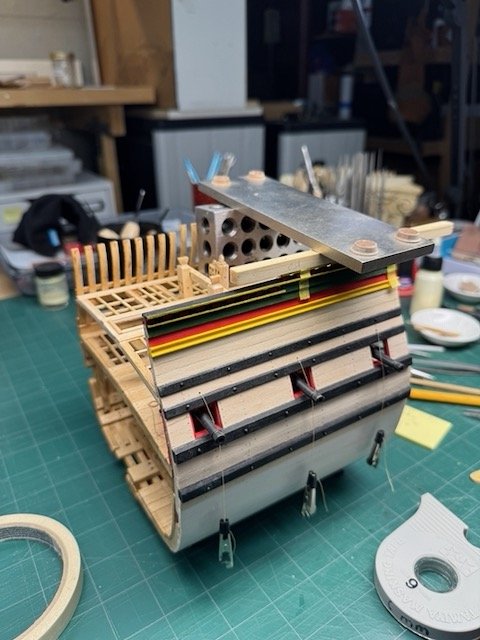
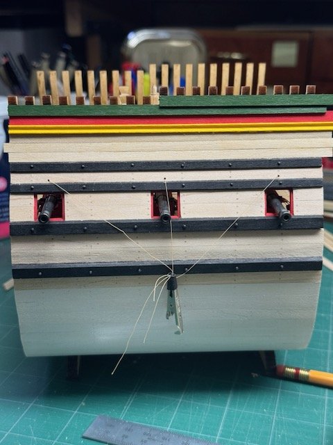
Trying to wrap up the last few tasks now. First is a photo of the capstan, all finished and installed. I won't install the bars, though, until it's ready to go in the case. I've installed some barrels in the hold, plus one you can barely see on the gun deck. They are glued down but not secured for sea! And I made and installed the galley chimney. I livened it up a bit with colors since this is, after all, a merchant ship. I was not sure how it ought to be fastened to the deck, so I settled on some stringers that mortise into ledges and deck beam. Quite probably the kit's ideas about this are more correct - it has the chimney sitting on a couple of deck planks. But, for esthetic reasons, I didn't want to put plank segments in that location, and what I did was the only alternative I could come up with. In the second photo you can also see the one pinrail has been installed. After that came the gun ports. There is a little bit of smoke and mirrors with them since there are no hinge segments attached to the hull. The tops of the gun ports are hard against the bottom of the 3rd wale, and I really don't know how that change in level between regular side planks and wale would be addressed in the hinges on a real ship. So (like at least one other build log for this kit), I just skipped over that detail. After the ports came the port main channel. There are six deadeyes, and I used the recently acquired chisel (with its blade narrowed down to 1mm) to cut the notches for them. The wood for the channel, incidentally, is AYC which I used because it's better to take sharp, small cuts. The channel hasn't been permanently installed yet, but the photos show it in position for fit checks. I've decided that I'll definitely make my own acrylic cover, rather than having one made for me. I have the experience to make something that's acceptable, but I intend to try to "up my game" on that score and see how close I can come to a box that looks really good. Ultimately I know that viewers will not see the box anyway - they focus on the model, but I have the tools, and the web offers enough good DIY information that I think it's feasible to make something that I'll be happier with. Thanks for looking. We're off to the Hudson Valley on Thursday for a long weekend vacation, so the model will be idle for a few days. Bob
- 76 replies
-
- 8
-
-
- Pinas
- kolderstok
- (and 2 more)
-
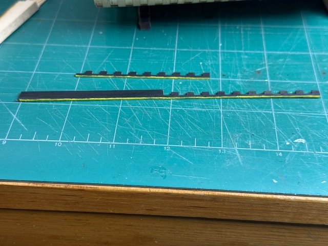
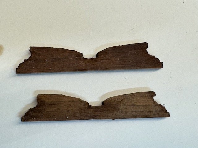
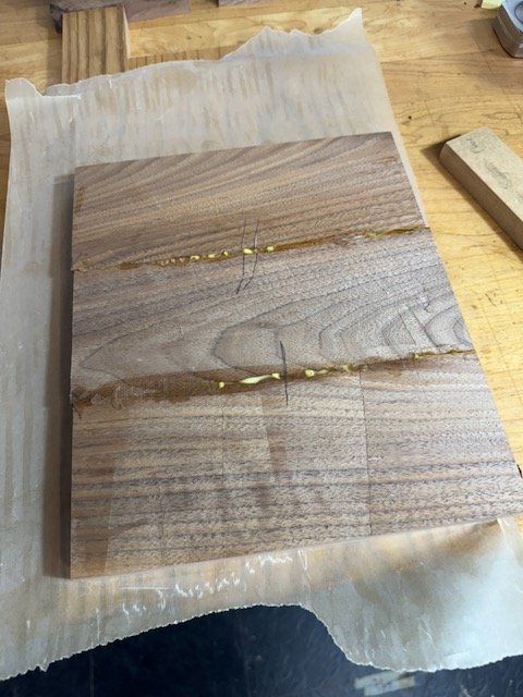
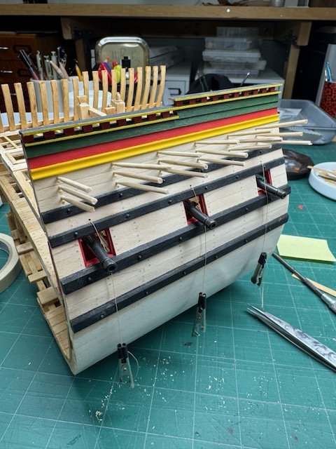
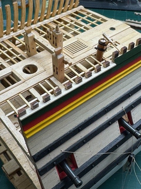
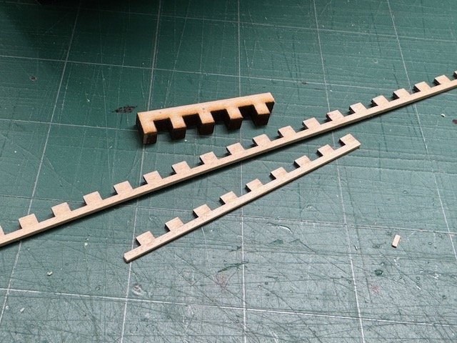
I'm getting close to the end now (since I'm only installing a stub mainmast), and this report is odds and ends of finishing details. First, I needed to finish the exterior of the port side. The planking above the upper deck is all clinker; the lowest of which has a double bead profile which I made with a scraper. I used AYC for that strip rather than the kit's basswood - the AYC is easier to scrape and it's painted so the wood color difference is immaterial. I'm using Kolderstok paint and the prescribed color scheme; it's nice stuff to work with and the colors are great. The uppermost plank's width of the side is not planked, so I had to make caprails with a lot of teeth. I thought it would be very hard to do a neat job with it until I realized that the kit comes with 4mm comb strips used to help with alignment when erecting the frames. So I just planed one of those strips down to 1mm, and had absolutely perfect spacing on the teeth. The upper caprail was just a straight strip, of course. After that, I added the treenails in the planking, stained the result (no pictures of that), and the exterior hull was complete. I'm in the process now of making a pinrail, but only its underside brace is installed so far. One of the last items will be placing some barrels around in interesting locations. Those shown here haven't been glued yet and may not end up as shown, but it shows what I'm thinking right now. Finally, I am working on the base. I usually wait too long to make the base, and this time is no exception. Here are two raggedy photos of the first steps. I'm using walnut, and didn't have a scrap piece anywhere near 8" wide, so I'm piecing it together - the photo shows it right out of the clamps, so some the squeeze-out hasn't been cleaned up. And the two pedestals are still rough from having been chopped out with chisels. I hope they're a little more attractive by the time the next photos are taken. Thanks for looking, Bob
- 76 replies
-
- 10
-
-
- Pinas
- kolderstok
- (and 2 more)
-
I wouldn't be quick to blame UPS. Everybody is being whiplashed by the constant fluctuations of very high tariffs. I don't think that UPS has any better idea than you or I what they'll be tomorrow. And be thankful that UPS will act as the broker in these transactions so it's still simpler (and I doubt more expensive) than it might be if there was an extra party in there handling the tariffs. My wife had a similar situation on an order from Germany a few weeks ago, but in her case there were more zeroes on the ends of those numbers. But it did all get resolved pretty quickly with active assistance from the shipper (I don't recall if that was UPS or Fedex).
-
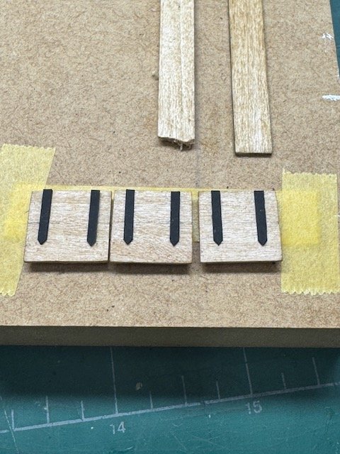
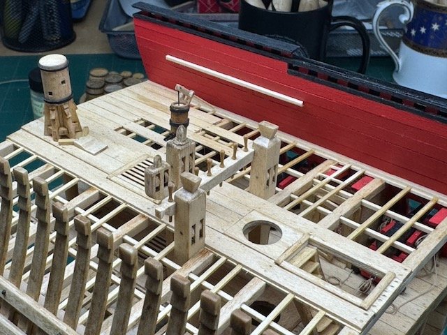
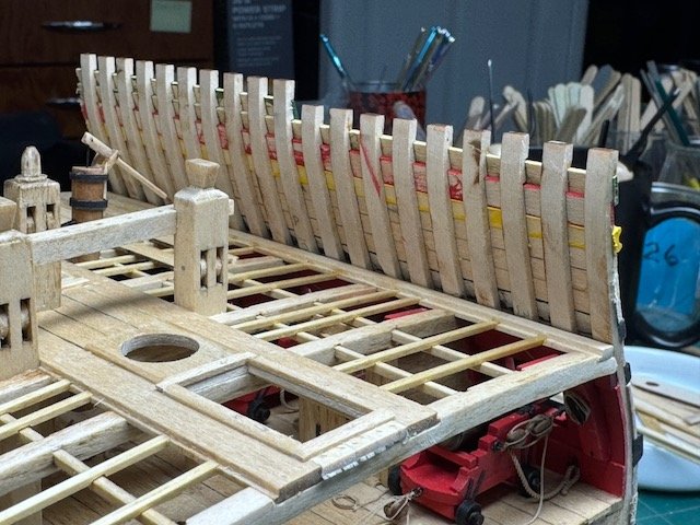
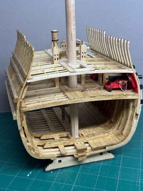
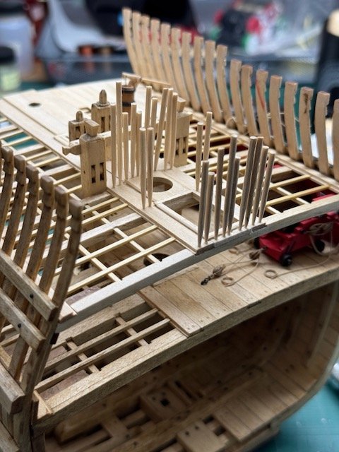
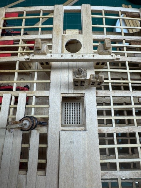
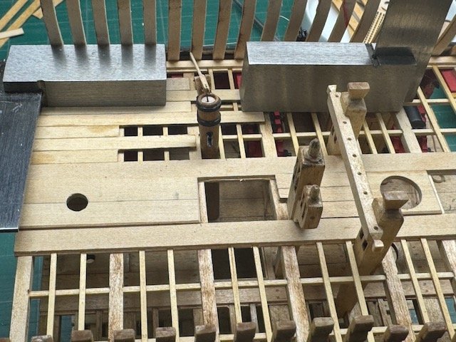
I'm making progress. After finishing the capstan (which isn't permanently installed yet) I did the partial planking of the upper deck, and then moved on to finishing the hatch combings and gratings. The kit comes with excellent laser-cut parts for making gratings in the Dutch 17th cent. style, and that's what I used. First was the lower deck - I'd originally thought to leave the hatch down into the hold uncovered, but thought better of that when I started this phase. I had left a rabbet on its combing, so fitting in the grating was pretty straightforward. Access was tight, but I could reach it from above or the after end of the model. You can see it in the picture below, looking straight down. Then I made the combings for the upper deck hatches as well as a grating for the open above the corresponding lower deck hatch. I have to say that the details of my combings are all different - I don't quite know exactly what they ought to look like so I ad lib each one based on the levels of decking around them and what the opening's like in terms of beams and such. But they all share the same 1mm deep by 2mm wide border at the top. So viewers are probably not going to notice my inconsistencies too easily. There is a hatch at the very front of the model where the slanted ladder will be installed. I've seen some build logs where the opening was covered with a grating, but I'm leaving mine completely open. That makes sense to me because the ladder gives it the appearance of an access to the lower deck that was frequently used. I didn't give the opening a rabbet to hold a cover of any sort: I probably ought to have done, but I couldn't decide how to make it look reasonable with respect to the ladder and the frame members around it. Yesterday I did the treenails on the upper deck; next is give it a stain so I can finish up the capstan installation. One last picture to show the current state, and I'll sign off. Thanks for looking, Bob
- 76 replies
-
- 7
-
-
- Pinas
- kolderstok
- (and 2 more)