abelson
-
Posts
467 -
Joined
-
Last visited
Content Type
Profiles
Forums
Gallery
Events
Everything posted by abelson
-
 Thank you for the compliment. It means a lot. The rigging may not be accurate but it's my interpretation of the plans, which leave you guessing in some places.
 -
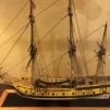
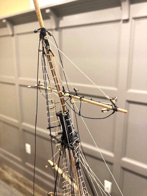
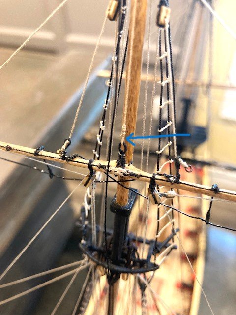
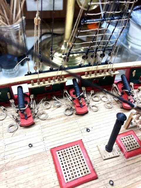
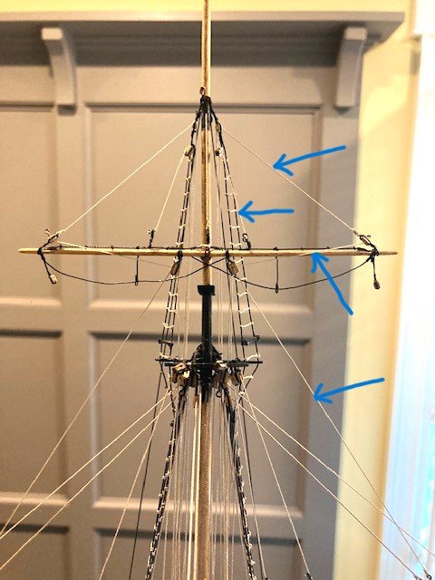
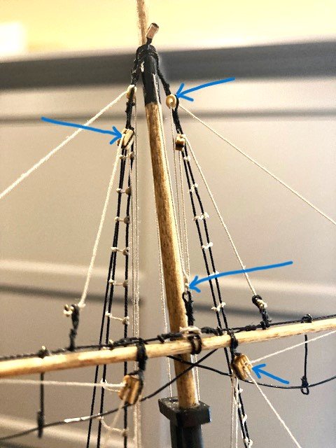
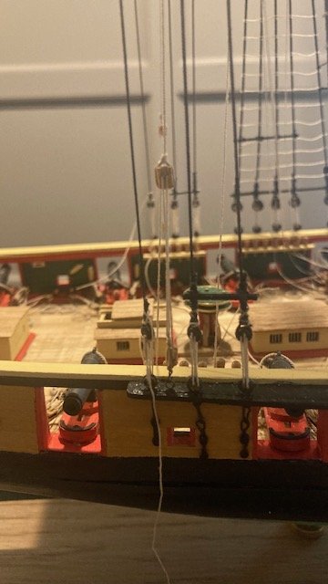
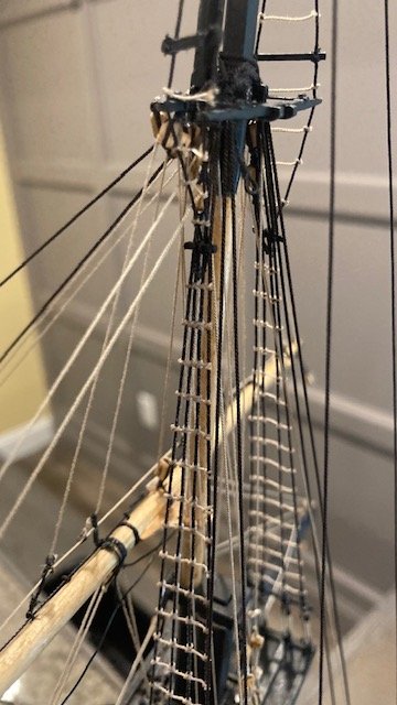
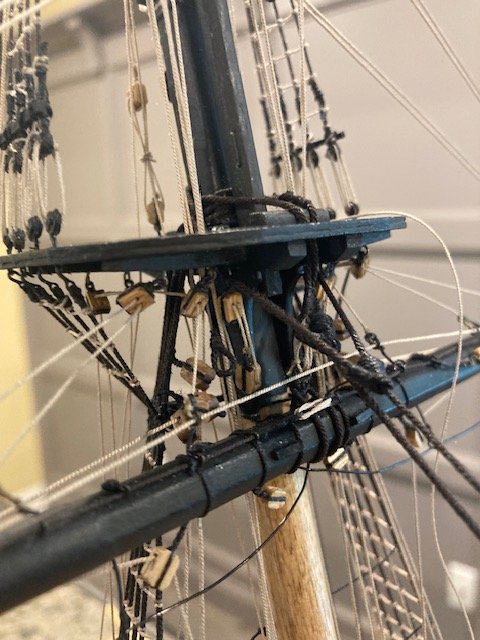
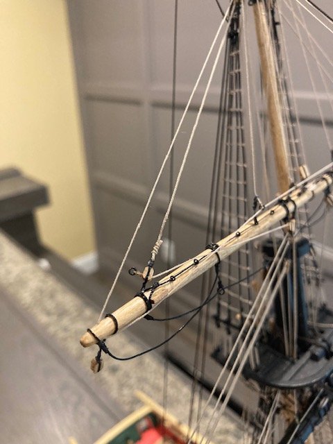
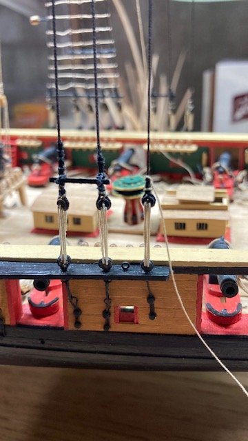
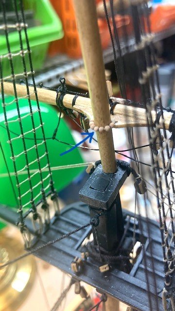
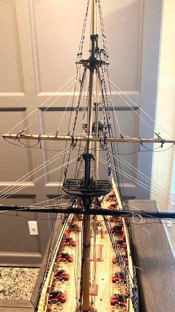
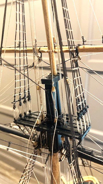
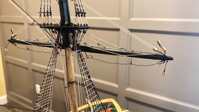
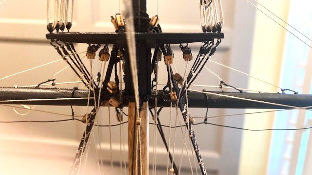
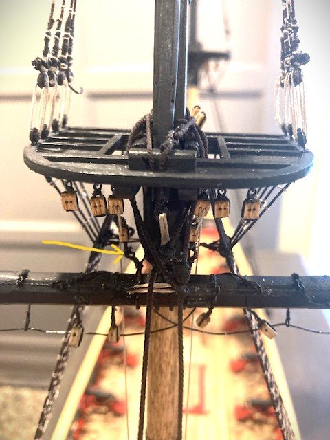
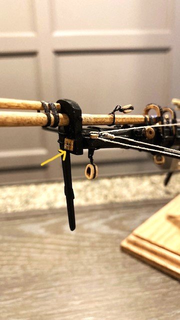
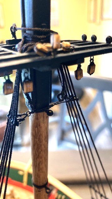
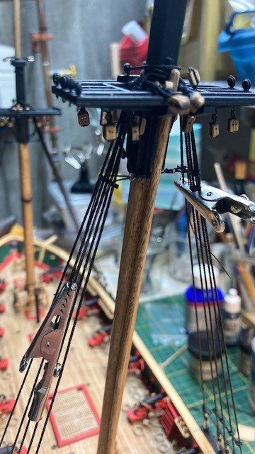
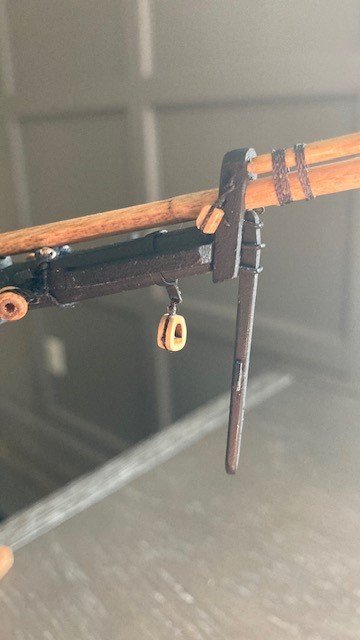
Stepped the fore topgallant yard. Used a .012” rope parrel. Fashioned the lashing for the topgallant tye using .018” black rope. Rigged the tye (.018”) and Halliard (.012”) as per Detail 6-D. Added the 3/32” clump blocks for the topgallant lifts (plan calls for 1/16” blocks which are not furnished). Seized the 1/8” single blocks to the topgallants shrouds as shown in the detail below the topgallant yard on Sheet 6. The plan calls 5/64” blocks which are not furnished with the kit. These blocks are for the topgallant bunt/leech lines. Completed the following rigging: Fore topsail yard clew lines (.008”). Seize to eye at topsail lift block. Passes through 3/32” double block shared with royal sheet. Belayed to pin 30 P&S at the pin rail. Passes through fairlead bar. Fore Topgallant yard bunt lines/leech lines (.012”). Passes through 5/64” block seized in shroud. Belayed to pin 29 P&S at the pin rail. Passes through fairlead bar. Fore topgallant yard lifts (.012”). Passes through thimble seized in shroud. Belayed to pin 33 P&S at the pin rail. Fore royal yard sheets (.008”). Passes through double block shared with clew line. Belayed to pin 34 P&S at the pin rail. Next up, step the royal yards.
.jpg.96bcf747890fd9d65eb3c7296d8c2702.jpg)
.jpg.cadb5153e286d454ddbe2990ea974b26.jpg)
-
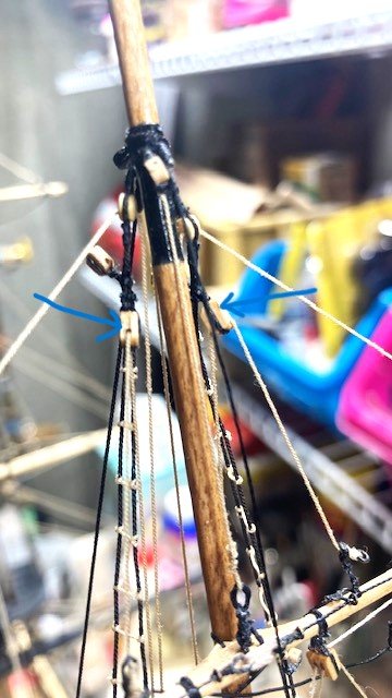
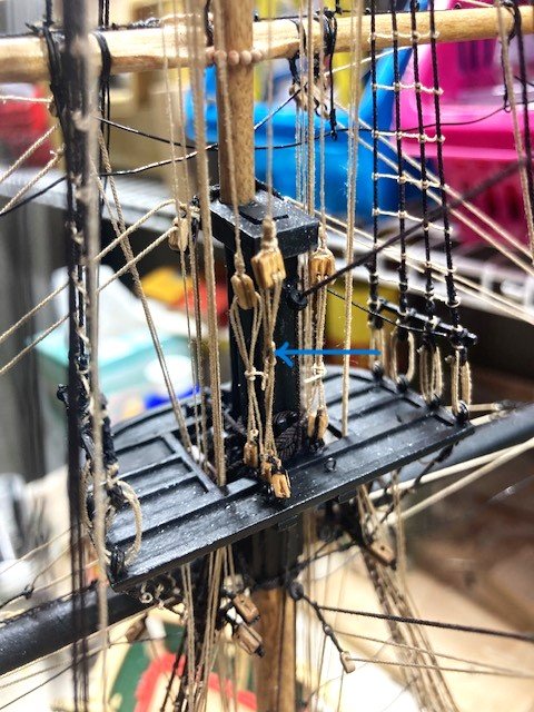
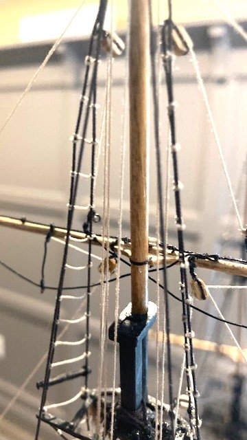
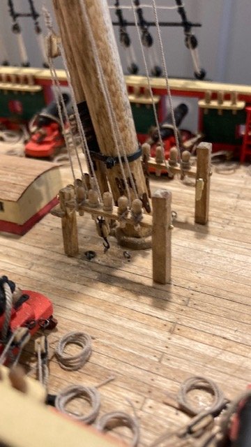
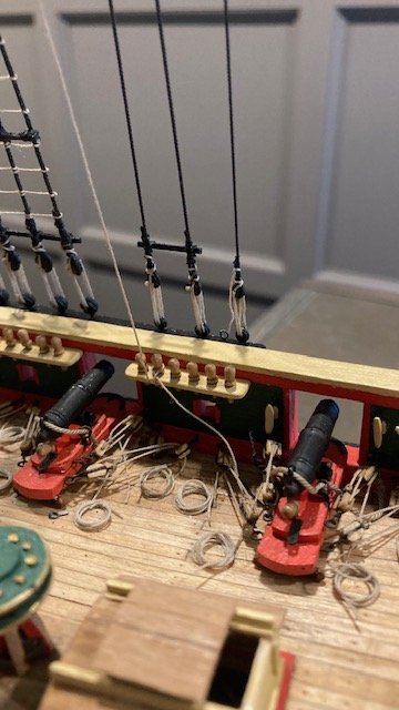
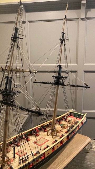
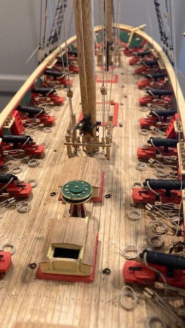
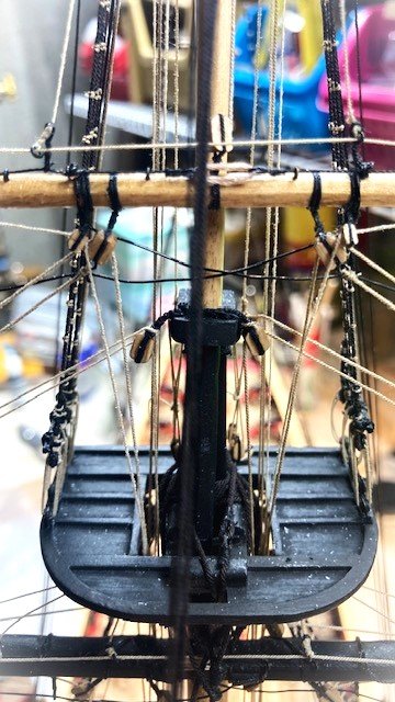
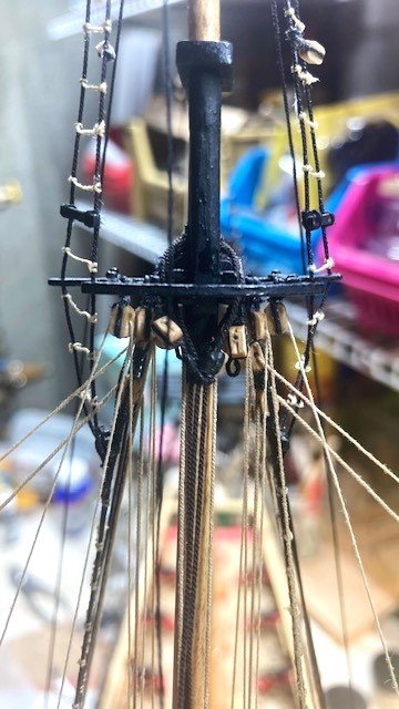
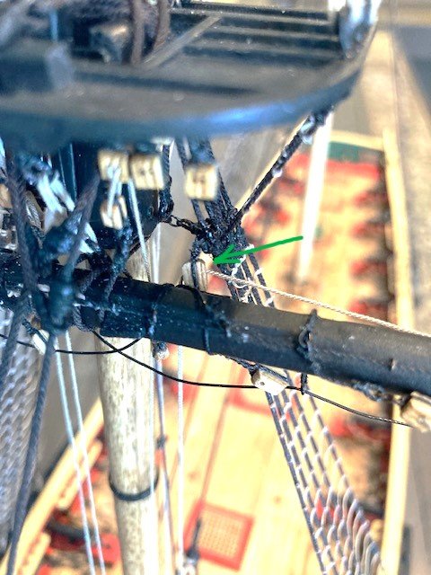
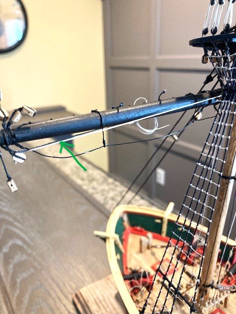
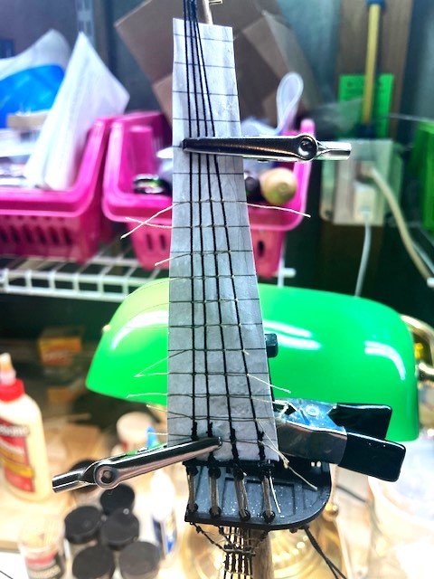
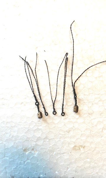
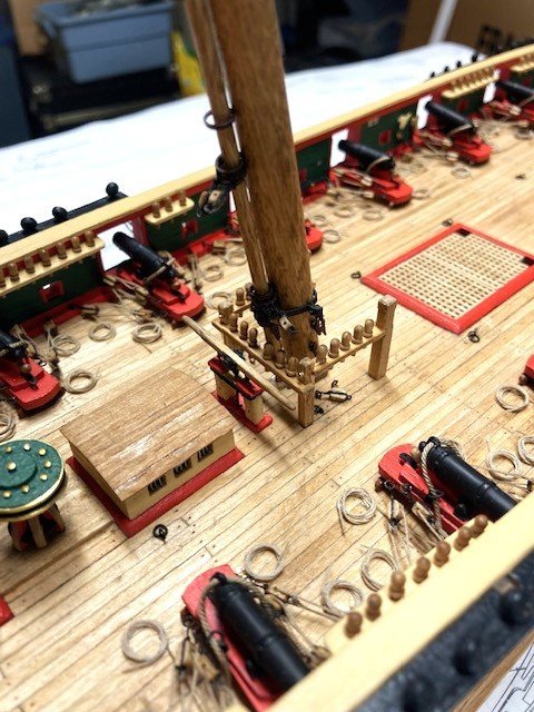
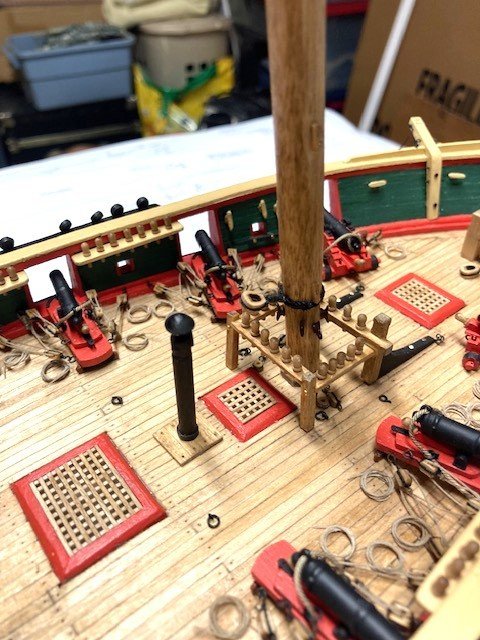
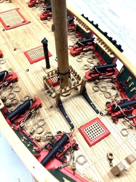
Started on the topgallant yards. I realized I didn't have enough parrel beads. I had previously ordered 1.5mm parrel beads from the Crafty Sailor. Apparently, they are no longer in business. I have not been successful in finding a supplier of 1.5mm wood beads. I researched the Model Shipways forum on Parrel Beads but didn’t find anything helpful there. So, I’m going to step the topgallant yards with a rope parrel. Stepped the main topgallant yard. Used a .012” rope parrel. Fashioned the lashing for the topgallant tye using .018” black rope. Rigged the tye (.018”) and Halliard (.012”) as per Detail 6-D. While studying the plans, I discovered that I had missed the 1/16” single clump blocks for the topgallant lifts. There is an enlarged detail of the clump block on the Main Mast Looking Aft on Sheet 6. I used 3/32” blocks because the kit is not furnished with 1/16” blocks. Completed the following rigging: Main topsail yard clew lines (.012”). Seize to eye at topsail lift block. Passes through 3/32” double block shared with royal sheet. Belayed to pin 64 P&S at the pin rail. Main Topgallant yard bunt lines/leech lines (.012”). Passes through 5/64” block seized in shroud. Belayed to pin 64 P&S at the pin rail. Main topgallant yard lifts (.012”). Passes through thimble seized in shroud. Belayed to pin 66 P&S at the pin rail. Main topgallant yard sheets (.008”). Passes through double block shared with clew line. Belayed to pin 69 P&S at the pin rail. Note: I find that it is easier to belay the ropes if I run them through the belaying pin holes in the pin rail and to then insert the belaying pins. The kit furnished walnut belaying pins were filed down slightly to fit into the holes. Whence the rope coils are added it won’t be noticeable that the ropes pass though the pin rail holes. Next up, repeat the process for the fore topgallant yard.
.jpg.915ae446de8e8b93383fb8aebed27849.jpg)
.jpg.1529d922bb3ff75698179cffdb79b0ab.jpg)
.jpg.1fa69432e59e3ef79bbecc60301b6b20.jpg)
.jpg.48109addf7320392edbd8468b7ee3f7f.jpg)
-
Thanks, Jason. Review my Fair American build log. It may be helpful.
-
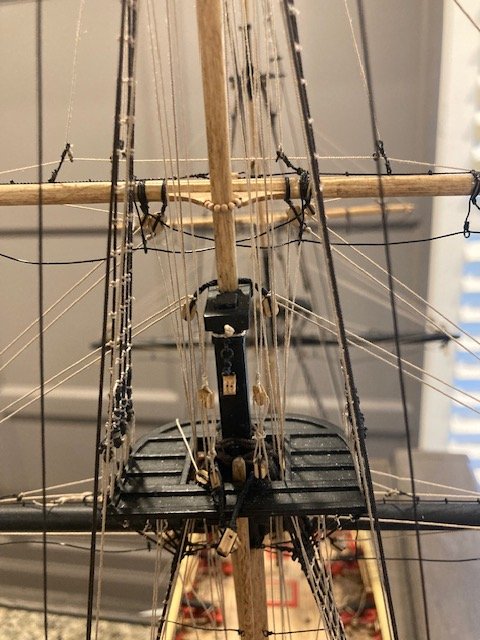
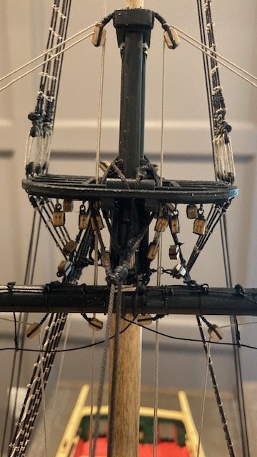
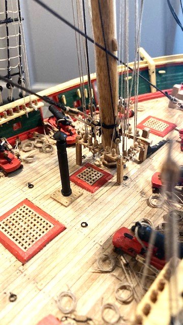
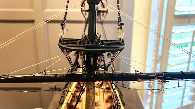
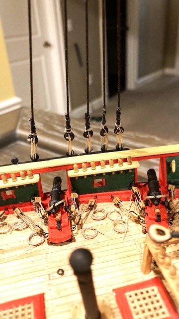
I forgot to add a 5/32” single block P&S on the fore most shroud at the main mast for the reef tackle. The Main Mast Looking Aft on Sheet 6 shows this block. The main course yard reef tackle is belayed to pin 58 P&S at the pin rail. Note: The pin location is not identified on the Main Mast Looking Aft but is noted in the Belying Plan. Stepped the main topsail yard. I added the bead parrel to the batten as per Detail 6-B and mounted the topsail yard to the main mast in the lowered position. Completed the following rigging: Main topsail yard Tye & Halliard (.018”) a la the fore topsail yard (see post #107). The halliards set up with a tackle and are belayed to pin 71 P&S on the pin rail. Main course yard clew lines (.018”). Belayed to pin 49 P&S at the aft fife rail. Main course yard bunt lines (.012”). Belayed to pin 61P&S at the pin rail. Main course yard leech lines (.012”). Belayed to pin 62P&S at the pin rail. Main course yard reef lines (.018”). Belayed to pin 62P&S at the pin rail. Main topsail yard bunt lines (.012”). Belayed to pin 42 P&S at the main mast. Main topsail yard leech lines (.012"). Belayed to pin 43 P&S on the main mast. Main topsail yard reef tackles per Detail 6-F. I used .012” rope. The reef tackles pass through the yard sheave and the upper block in the top mast shroud and are set up with a tackle belayed to itself. Main topgallant sheets (.012”). Belayed to pin 60 P&S at the pin rail. Seized a small ring (cringle) on the end of the rope at the block seized into the topsail lift. The cringle is for the topsail clew which will be added when the main topgallant yard is stepped. Main topsail yard lifts (.018”). The lefts pass through the lower block seized in the top mast shroud and belay to pin 57 P&S at the pin rail. Here are some photos. Next up, the Topgallant Yards.
.jpg.d37784c2c747a334b1dd895068861dc5.jpg)
.jpg.79575b8de58bb394600ed2bb0a694ed7.jpg)
.jpg.1d253df5fdde7b894aa0e52c3d96d093.jpg)
-
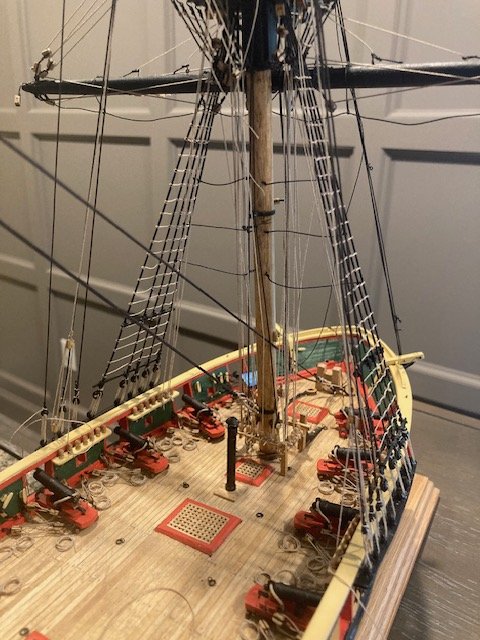
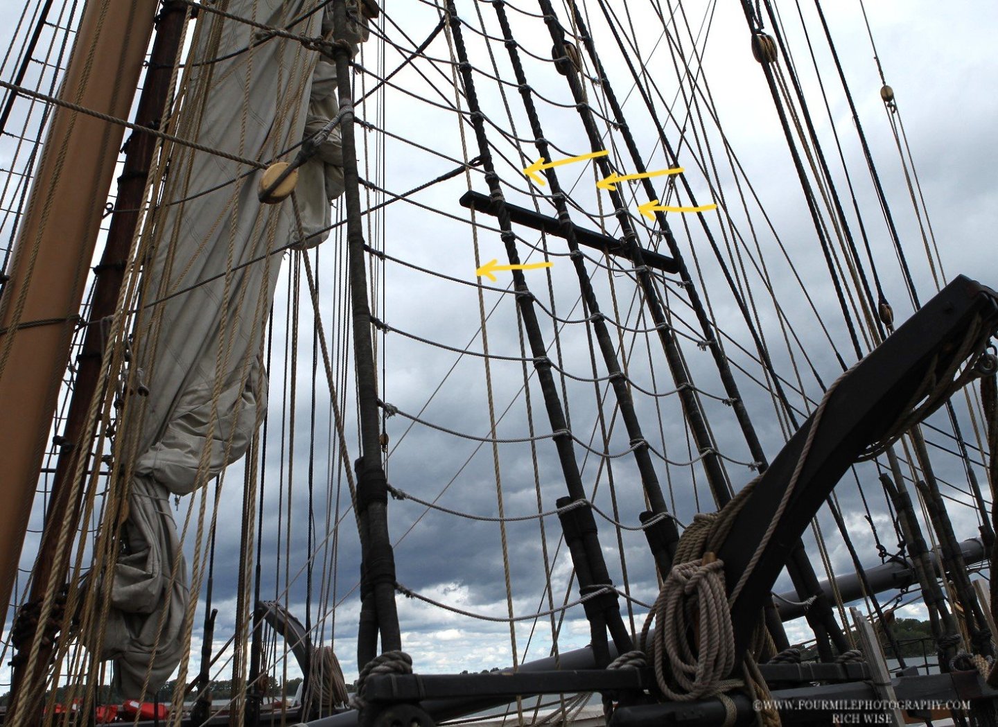
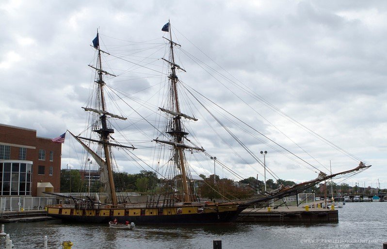
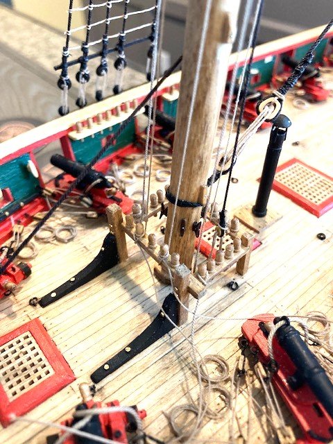
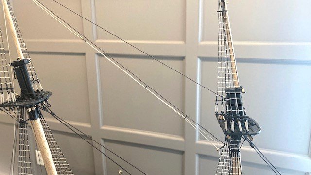
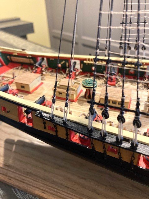
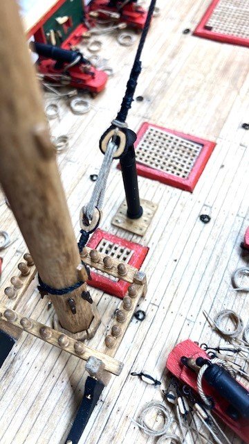
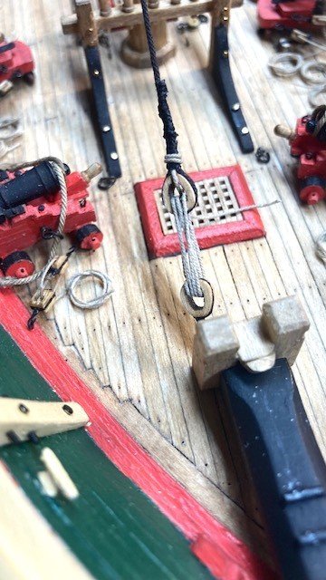
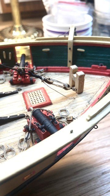
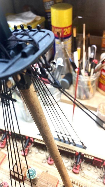
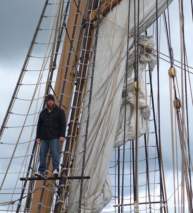
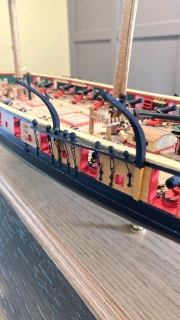
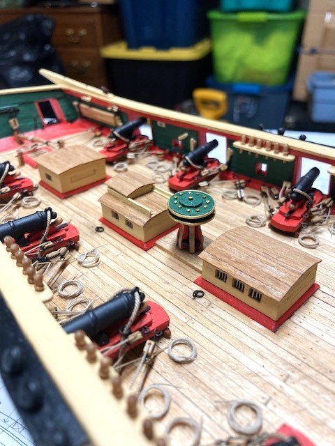
Completed the crane lines (shroud foot ropes). Used .012” rope. The replica ship has 5 foot ropes at the main mast and 3 ropes at the fore mast (see photo). I cut out a copy of the detail on Sheet 5 and used it as a guide to get the spacing of eyebolts on the masts. I drilled a hole P&S at each location. I didn’t eye splice the ropes (too difficult), just tied a simple half knot. Suggestion: Add the eyebolts before stepping the masts.
.jpg.6a622c08c583b4a5ee2887fbd4dd705a.jpg)
-
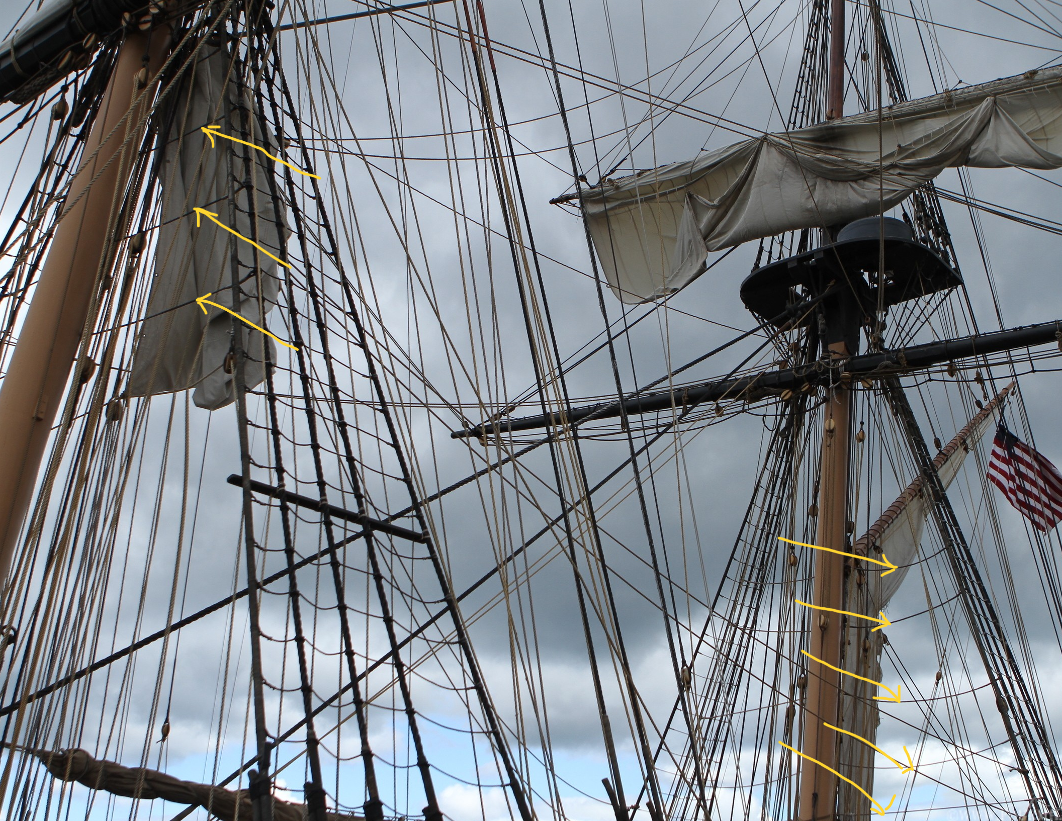
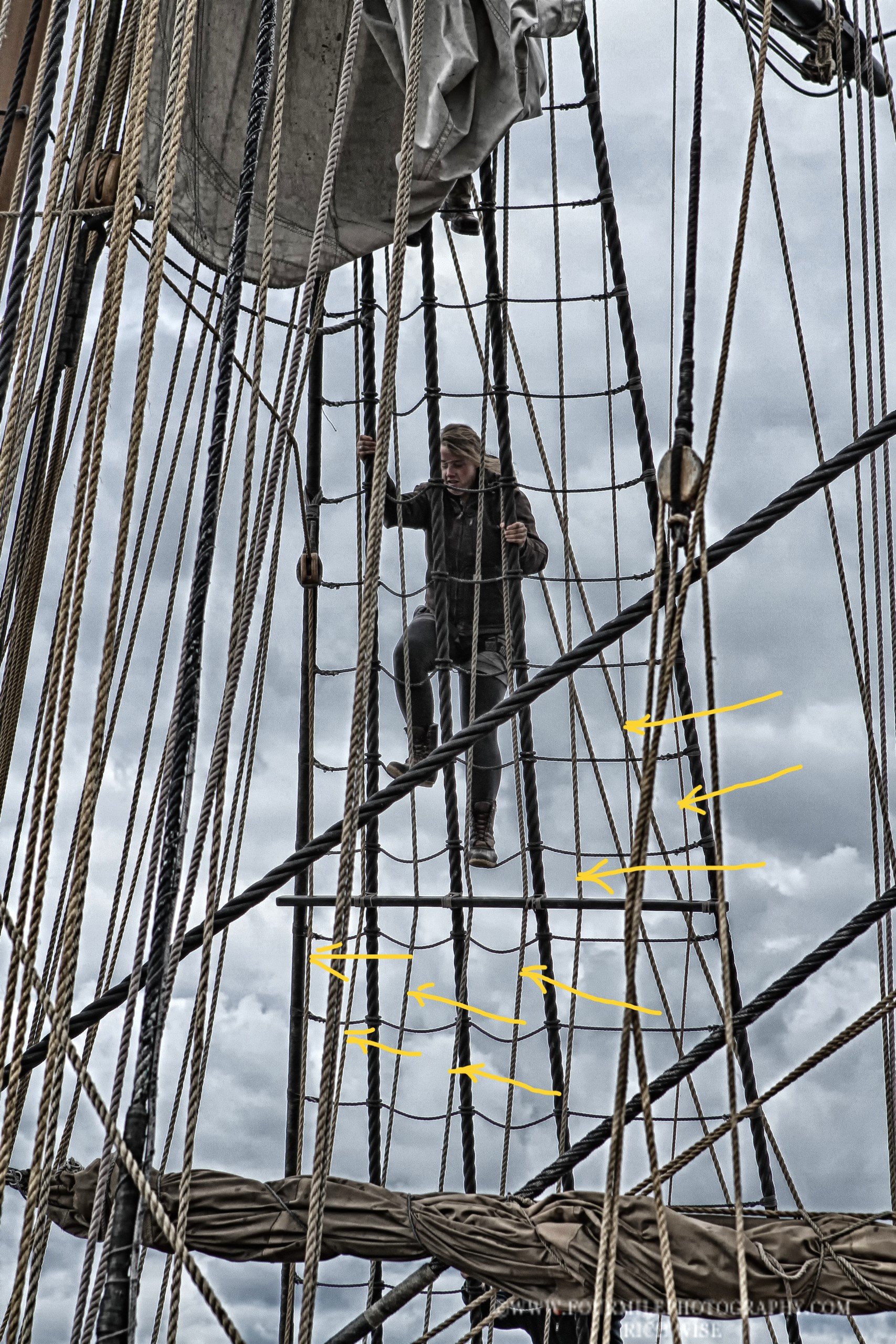
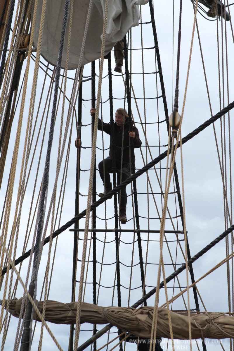
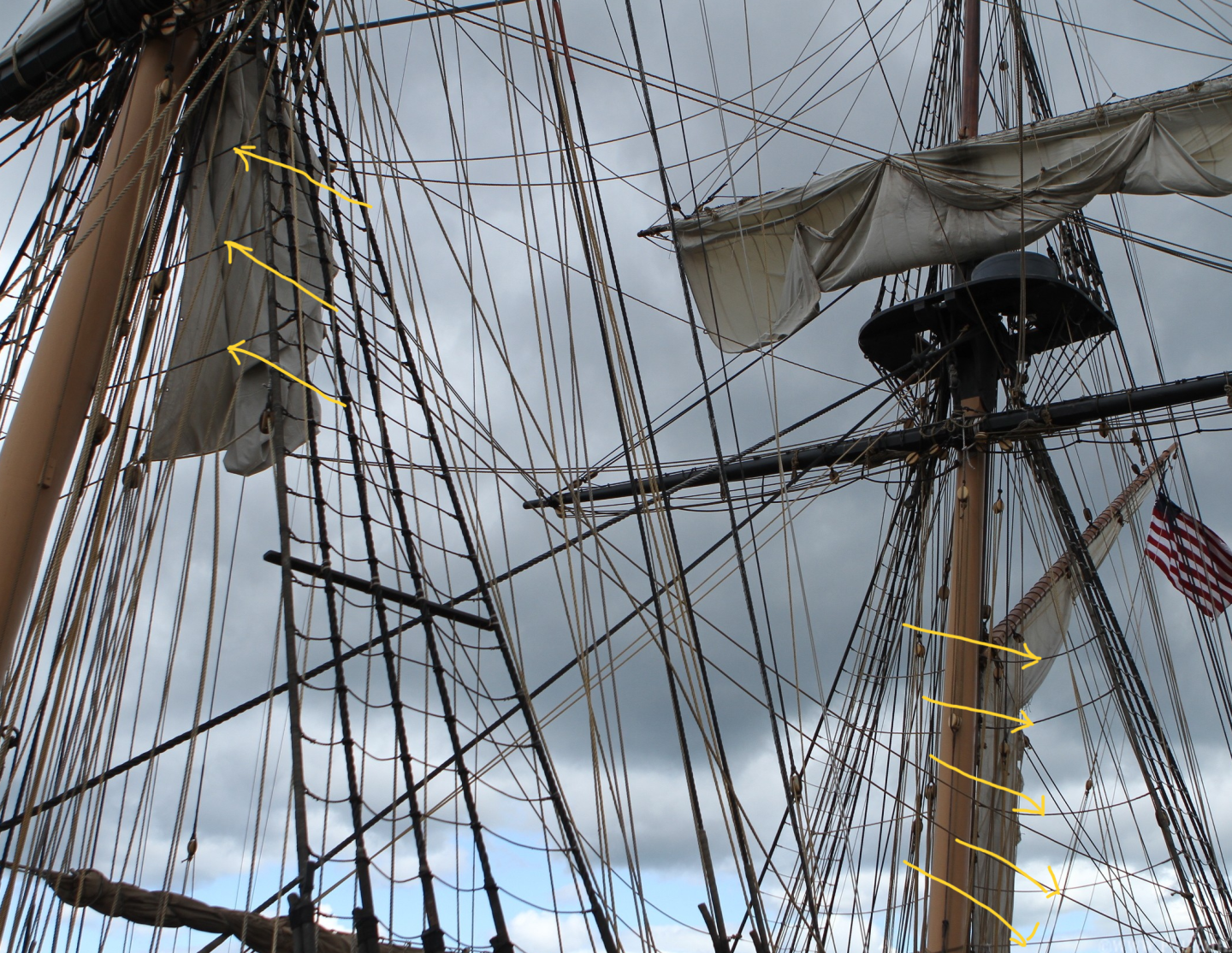
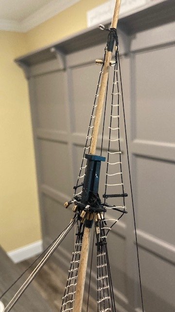
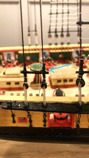
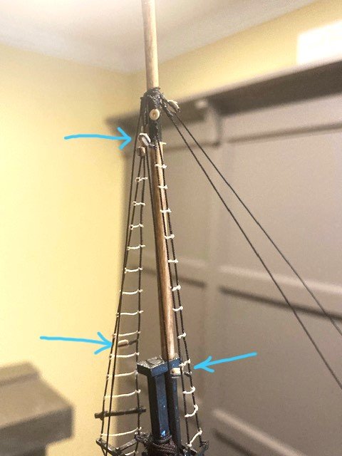
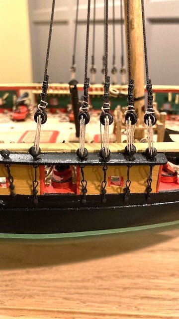
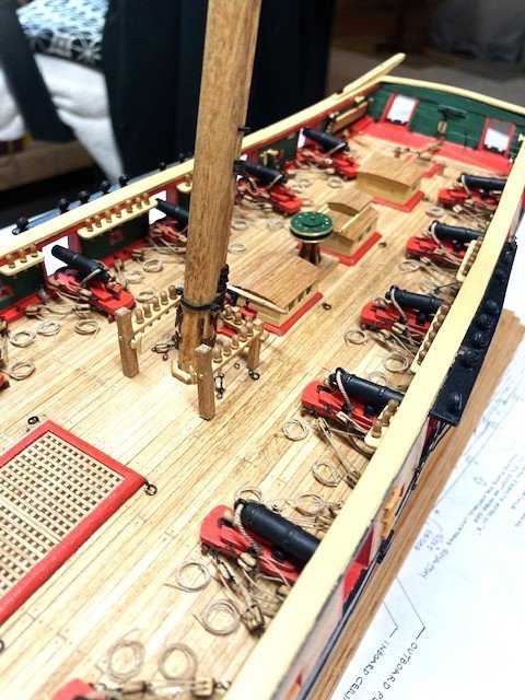
Rigged the main topgallant mast shrouds (.018” rope) and rat lines (.008” rope). Added 1/16” single blocks (P&S) to the fore shroud near the hounds as shown in Detail 6-A. The blocks are for the fore royal yard braces. Added the 3/32” single block at the hounds for the Topgallant Stay Halliard. Rigged the Topgallant Back Stays. I used .018” rope (the plan calls for .016”), and .008” rope for the lanyard. Stepped the main course yard. Rigged the .012” lanyard for the course yard sling and the course yard truss per Detail 6-G. Rigged the main lower yard lifts as per Detail 6-C. The lift tackles are belayed to pin 50 P&S at the aft fife rail. Used .018” rope for lifts. Rigged the main topsail sheets with .018” rope. The sheets are belayed to pin 46 P&S at the aft fife rail. Note: While studying the Main Mast Looking Aft on Sheet 6, I realized that I forgot to run the rigging lines through the fairlead bars as noted on Sheet 5. The plans aren’t clear which lines run through the fairlead bars. Looking at photos of the replica ship, it appears that there are 8 lines that run through the fore fairlead bars and 4 lines that run through the main fairlead bars (see photos). Presumably, the lines are the main course braces , main topsail braces, fore course buntlines, fore course leechlines, fore topgallant buntlines, fore topgallant clew lines, and the main top gallant braces which are belayed at the fore most pin rail, and the main topgallant stay sail sheets, main topgallant sheets, main course, buntlines, main course leechlines, fore royal braces, main topgallant clew lines and bunt lines, and spanker throat Hilliard which are belayed at the second pin rail forward of the stern. Going forward, I will attempt to run the various lines (.008" and .012") through the fairleads - lines greater than .012" will not pass through the fairlead bar. Next up, I'm considering adding the crane lines (shroud footropes) shown on Sheet 6.

-
Continuing with the fore topsail yard, I added the bead parrel to the batten as per Detail 6-B and mounted the topsail yard to the fore mast in the lowered position. Note: I raised the yard so that the foot ropes clear the top mast cap - just a preference. Also, the kit is not furnished with the beads for the parrel. I ordered them from Crafty Sailor (I believe they are no longer in business). Studied Sheet 6 before embarking on fore topsail yard rigging. Removed the bowsprit for fear of snagging it while rigging the fore topsail yard - highly recommended. Rigged the topsail Tye & Halliard per Detail 6-B. Used Syren .018” rope (plan calls for .020”) and .012” rope (plan calls for .014”) for the halliards. The halliards are belayed to pin 37 P&S on the pin rail. Setup the Topgallant Backstays (.018 rope) with 1/16" bullseyes and .008” lanyard. Rigged the fore topsail yard Bunt lines and Leech lines. I used Syren .012” rope (plan calls for .014”). Fig.9-12 in the Instruction Manual says these lines are knotted off or omitted if the there is no sail or furled sail. Instead of knotting off the leech and bunt lines, I seize a small ring to the end of each rope for passing the reef tackle. The bunt lines are belayed to cleat 12 P&S on the Fore mast. The leech lines are belayed to pin 18 P&S on the fore fife rail. I left the lines slack until the fore course yard Clew Lines are rigged and securely belayed. Rigged the fore course yard Clewlines and the fore topsail yard Sheets as per the Main Mast Looking Aft on Sheet 6. I used .018” rope for the clewlines and .012" rope for the sheets. The clewlines are belayed to pin 20 P&S on the fore fife rail. The Sheets are belayed to pin 19 P&S on the fore fife rail. I seized a small ring to the end of the sheet rope for the top sail yard Clewlines (to be rigged later). Lastly, I rigged the fore topsail yard Reef Tackles as per Detail 6-F. I used Syren .012” rope. Next up, the main topgallant royal mast shrouds.
.jpg.ba3affbb600bd24e47bb189c530da3d8.jpg)
.jpg.f6659744d0eb625a83f60a47e11b40ba.jpg)
.jpg.b64c2049741dbfeec0745c19aa4b0103.jpg)
.jpg.715ca9166914312f79a4a60450b1445c.jpg)
-
Steve, I have not yet rigged the outer jib stay tackle. I only added the 1/8" double block which is hooked to the lower eyebolt on the port side of the bowsprit cap. The .014" "fall" is attached to the fiddle block and is reeved through the double block and through the lower sheeve of the fiddle block and then back through the double block and the upper sheeve of the fiddle block and then "belayed to itself" as shown in Fig. 8-6 in the Instruction Manual. I presume the access to the jib stay tackle was via the manropes netting.
-
Thanks so much for the compliments. I'm glad you find the build log helpful - that's the intent. I frequently study the plans and make a to-do-list. Sometimes I'll make a sketch to help visualize and clarify certain rigging. I frequently review other build logs, albeit there aren't many. I also find photos of the replica ship by Rick Wise helpful (www.fourmilephotography.com/FlagshipNiagara). My approach is to be methodical and sequence the work so as not to interfere with completed work, especially rigging. One of the problems in advancing the build, particularly the bowsprit, is to not snag something, which is easy to do. I try to be very conscious and cautious about that. I'm almost 24 months into this build. As the old proverb says, "slow and steady wins the race." Keep on sailing.
-
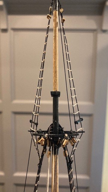
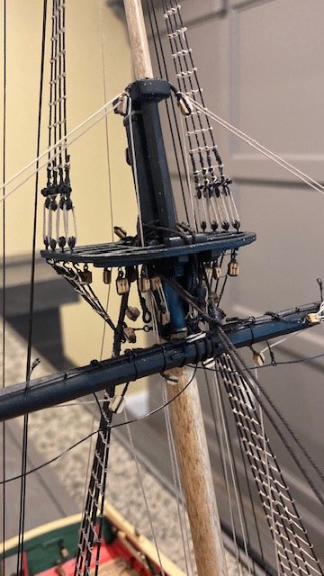
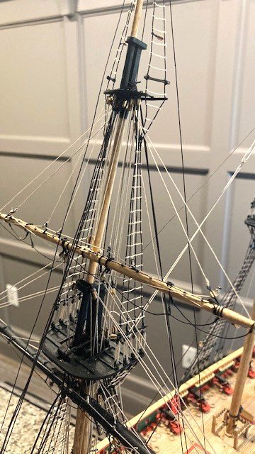
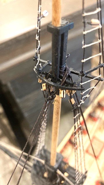
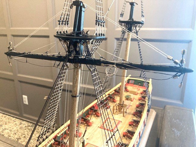
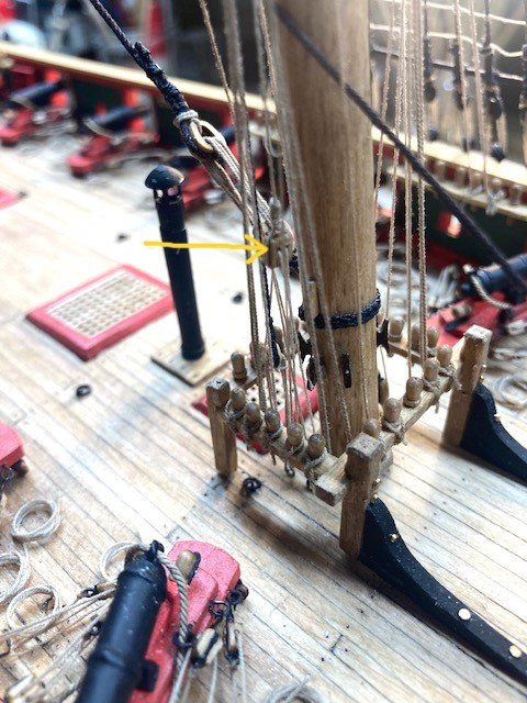
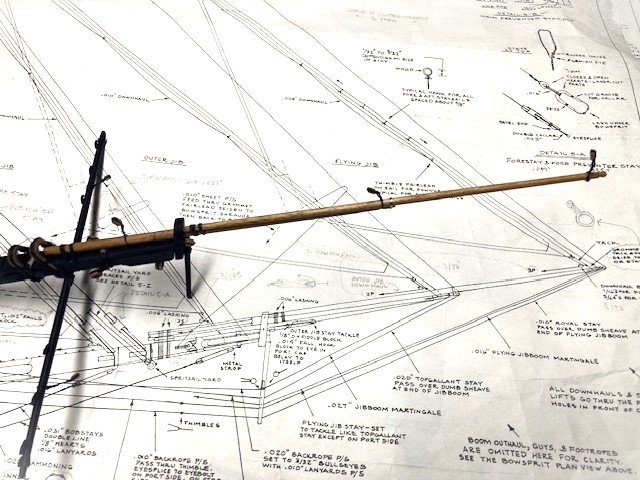
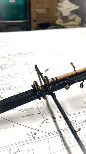
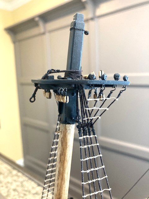
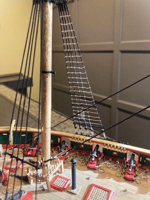
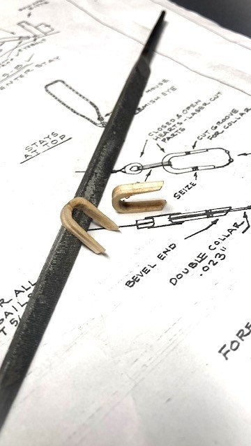
Stepped the Fore Top Gallant Royal Mast. Completed the Top Gallant Royal Mast shrouds (.018”- plan calls for .020”). Seized a 3/32” thimble in each pair of shrouds per Detail 5-E. I used .008” tan Syren rope for the ratlines. Added the sheer pole. There are four blocks that need to be seized to the shrouds: 5/64” on the aft shroud P&S for Main Royal Yard braces and 5/64” on the fore shroud P&S for Main Topgallant Yard braces. These blocks are shown in Detail 6-A on Sheet 6. Added 3/32” block at Top Gallant Royal Mast hounds for the Flying Jib Halliard as shown on Sheet 5. Fashioned the Inner Jib Stay (.025”- plan calls for .027”), the Fore Top Mast Stay (.025”- plan calls for .027”), and the Fore Topgallant Stay (.018”- plan calls for .020”) and the Flying Jib Stay (.012”). The stays are set up temporarily, as is the bowsprit. Except for the Flying Jib, each stay has a mouse that was made from 3/32” dowel. Each mouse was painted black rather than served with sewing thread. Seized 1/8” single blocks to the fore top mast crosstree for the Inner and Outer Jib Stay Halliard as shown on Sheet 5 and to the main top mast crosstree for the Fore Topgallant Yard braces. These are in addition to the 6 blocks previously seized to the crosstrees. Added the collar with thimble at the Top Gallant Royal Mast hounds. The collar is for the Main Royal Stay shown in Detail 6-F. Rigged the Top Mast Back Stays with 7/64” deadeyes and .012” tan lanyards. The plan calls for .027” rope for the stays which is not furnished with the kit. I used Syren .025” rope. The fore Back Stays need a sheer pole (not shown) to prevent them from twisting. Added a sheer pole on Main Top Mast Back Stays (previously rigged) as shown on Sheet 5. Insert photos 1326 I’ve been contemplating permanently attaching the bowsprit but have decided to attach the Fore Top Sail Yard before the various Fore stays are permanently rigged. I had previously inserted pins in the masts for the yards based on the yards being in the raised position. However, I’m considering attaching the yards in the closed position, basically because I like the look of them in the closed position in some other build logs and in photos of the replica ship (see photo). Stay tuned.
.jpg.e0359b1190ba5a006329ad596c53ffe0.jpg)
.jpg.d1bb37835842cc7d623539d1152537df.jpg)
.jpg.6a53bf90e9559fa8e9a1e60378d625d5.jpg)
.jpg.f89475ce2c2cddc040f200b96bf1e79c.jpg)
.jpg.edd35b6a8f3ac806d4027c8c21a67330.jpg)
.jpg.540688314f83573f11d6af3c98d33cdb.jpg)
.jpg.a9617ff9dcc55eeafb561ed5e80ff70f.jpg)
-
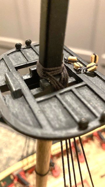
Made some significant progress on rigging the Fore Course Yard. I struggled with attaching the course yard to the pin on the fore mast. I decided it was easier to remove the pin from the fore mast and to secure it to the course yard. Added the course yard lanyard (.012”’tan). Fashioned the truss with eye splices from Syren .025” black rope. Wrapped the truss around the yard and mast and seized the ropes as shown in Detail 6-G (forgot to take a photo). I used black sewing thread to seize the rope - this was little tricky. I tied a simple knot, secured it with CA, and trimmed the ends. Added a 1/8” single block to each eye splice for the truss fall and rigged the truss falls (.012” tan). The truss falls are belayed to pin 15P&S on the forward fife rail as noted on the Belaying Plan. Added a 5/32” single block P&S to the forward most shroud as shown on the Main Mast Looking Aft. This block is for the Reef Tackle. Rigged the Reef Tackles. The plan calls for .016” rope which is not furnished with the kit. I used Syren .018” rope. The tackles are belayed to pin 17P&S on the Belaying Plan. Added two 5/32“single blocks (P&S) that are seized to the aft most shroud above the futtock stave on the fore mast. These are for the main course yard braces and the main top sail yard braces as shown in Detail 6-A. It would have been easier to add these before the upper shrouds were added. There are also a similar set of blocks for the fore mast course yard, braces and the fore mast topsail yard braces that are seized to the foremost shroud on the main mast between the main top and the course yard. Added the Leech lines (.012” - the plan calls for .010”), Bunt lines (.012” tan), Top Sail Sheets (.018”-plan calls for .016”), Lower Yard Lifts (.018”-plan calls for .020”), and a Bolt Rope (.018”). Instead of knotting off the leech and bunt lines, I seize a ring to the end of each rope for passing the bolt rope. The Lifts are set up with a tackle as shown on Detail 6-C and belayed to pin 23P&S on the Belying Plan. There are two bunt lines P&S that are belayed to pin 27 on the Belaying Plan. The leech lines are belayed to pin 28P&S. The top sail sheets are belayed to pin 16P&S. Not sure what to do next. I was planning to add the top mast back stays and the inner jib back stays but I now think I will step the fore topgallant/royal mast.
.jpg.b384ebacbb067022d272a56a2de70cdb.jpg)
.jpg.e0578c8bd52e8bce6aa78fce518c874f.jpg)
-
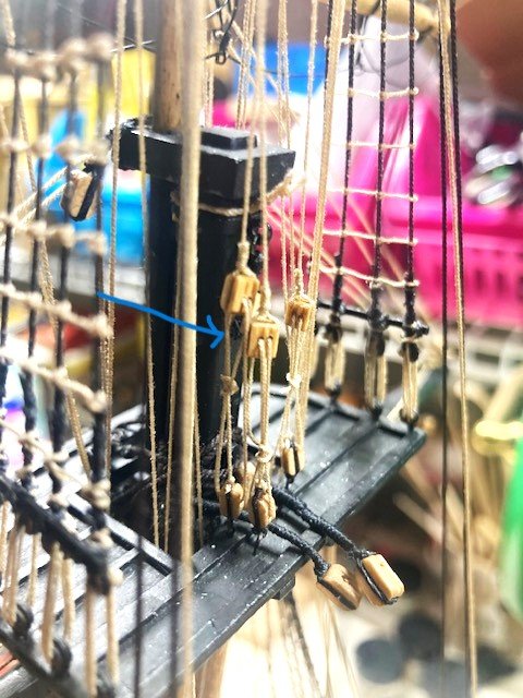
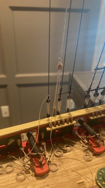
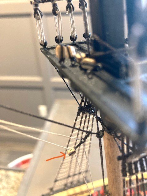
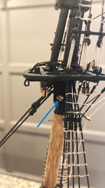
Completed the main mast and main top mast rat lines. Began work on the top mast shrouds. The first pair of shrouds have 1/8" single blocks. Note: the blocks are not in the same orientation. As can be seen on Detail 5-G, the reefing block is facing fore to aft, and the lift block is facing port to starboard. I used Syren .025” rope (the plan calls for .023” line which is not furnished with the kit) for the shrouds. The Burton pendants were made with Syren .018” rope (the detail calls for .016” line which is not furnished with the kit). It isn’t clear from the plans and the instruction manual just how the shrouds are placed. I presumed they are placed first pair/second pair portside, first pair/second pair starboard side. Completed the top mast shrouds with rat lines same as the main and fore mast. Added the sheer poles and staves. Before proceeding, this is a good time to review the plans and instruction manual and to update the To Do List. I decided to add the Top Mast Back Stays followed by the Top Mast Stay and the Spring Stay. The back stays are set up with 3/32” deadeyes and lanyards (.008”). The Top Mast and Spring Stays are rigged with a lanyard (.012”) and 3/32” bullseyes to eyebolts adjacent to the fore mast and inside of the fife rail as shown in Detail 5-H. Note: The eyebolts are not shown on the Belaying Plan. According to Detail 5-H, the lanyards are different lengths (not sure why). While studying the plans, Sheet 5 specifically, I discovered that there is an 1/8” single block that is seized to the fore stay collar on the port side (see photo). This block is for the Fore Stay Sail halliard. A note on Sheet 5 says the forestay sail is a storm sale and not generally rigged at the forestay. The Fore Stay Sail is most often rigged at the main stay. So, an 1/8” block needs to be added to the main stay as well. If you plan to add this block, make sure you do it before you rig the Fore Stay and Main Stay. Also, note that there is an 1/8” single block seized to the main stay over the main hatch and on the fore stay over the forecastle hatch. These blocks are for a stay tackle. Further, there is an 1/8” clump block with falls and pendants for the Inner Jib and for the Outer Jib. I’m not certain how or whether to rig these. There is also a similar, more complex, arrangement of blocks, clumps, falls, and pendants for the Top Mast Stay Sail. Added grommets and 3/32” single blocks to the bowsprit and the jibs for the Outer Jib Downhaul (2P), Fore Staysail Downhaul (2S), Flying Jib Downhaul and Fore Top Gallant Stay Fall (3P), and Inner Jib Downhaul and Flying Jib Stay Fall (3S). It’s best to add these blocks while the bowsprit and jibs are off ship. The downhauls pass through the fairlead holes in the chock rail and are tied off on the forward pin rail as noted on the Belaying Plan on Sheet 6. Planning ahead, I made the sister hooks for the bowsprit shrouds, the 1/8” single blocks with hook for the Spritsail Yard lifts and the 1/8” double block with hook for the Outer Jib Stay tackle. Note: Sheet 5 shows this 1/8” double block being hooked to the lower eyebolt on the cap, but the Bowsprit Plan notes the 1/8” block for the Spritsail Yard Lift is hooked to the same eyebolt. Fashioned the mouse on Top Mast Stays, Spring Stay, and Inner Jib Stay from 3/32” dowel. Predrilled the dowel before shaping the mouse. Made an eye at one end of each stay. The size of stay throat is arbitrary. Secured the mouse to the stay with a dab of CA. I decided to paint each mouse black rather serve them with sewing thread. Added a 1/8” single block to the Top Mast Stay throat for the stay Halliard, a 3/32” single block with thimble for the Downhaul, and the fairlead to the Top Mast Stay for the halliard tack. .Also, added 2 thimbles for the Halliard Tack. The thimbles were made with 5/64” split rings and .008” rope. Rigged the stay halliard (the plan calls for .014” line which is not furnished with the kit. I used .012" Syren rope) with 1/8" single block with hook, the halliard tack (.010" rope), and the downhaul (.010" rope). The tack and the downhaul are a continuous rope that passes through a split ring attached to the hook on the 1/8" block. The tack end of the rope passes through the 3/32" block thimble and the fairlead and is belayed on the fife rail (22 on the Belaying Plan). The downhaul end of the rope passes through the two thimbles on the top mast stay and the 3/32" block and is belayed on the fife rail (22). Set up the Main Topmast Stay and Spring Stay with bullseyes and lanyards as per Detail 5-H. The lanyards are belayed to themselves Moving on, I was planning to add the fore top mast back stays next, but I'm now contemplating adding the Fore Course Yard so that the lifts can be rigged while the back stays are not in the way. Need to study the plans some more. Stay tuned.
.jpg.5a836f57430d5ff95634b533e7c92a60.jpg)
.jpg.0cf2c36260effa25a7e7956feb189c1f.jpg)
.jpg.1b128ca4d59c9d3568d836d0ba3641f0.jpg)
.jpg.971c90ef62594f142edd2126eaaf440f.jpg)
.jpg.8e1eb2de9f991c8ad96306e488115a7c.jpg)
.jpg.10b383374bc951f19f95c07d1e8fffa1.jpg)
.jpg.3a6bc959c02d0fb5ad5cb1bdc7e73789.jpg)
.jpg.623ac92459231c977b92fa7efa5f3cdf.jpg)
.jpg.01b9947647f77737ef508d9977a40a73.jpg)
.jpg.46330776fb0ce456fb9f3591fc92f453.jpg)
.jpg.bf487898e6ceae510f5548c6486e6de5.jpg)
.jpg.ea13806a53003dfadf31d5cbf0439b71.jpg)
.jpg.32d1ac1ba850f8742864f973cf058142.jpg)
.jpg.381a403fcf96bd02564726150660239a.jpg)
.jpg.b460a0ff0a2f94265e01631afc21e1cc.jpg)
.jpg.03fe75775ef2e3f2edcdf622bf751526.jpg)
-
Looking good, Tom. Nice work.
-
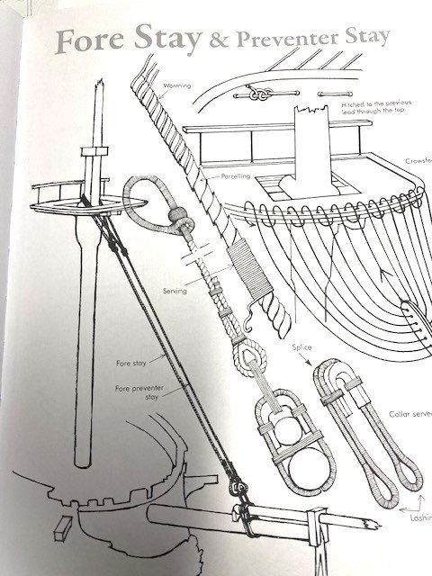
Completed the Main and Fore Mast Stays. I used .045" Syren line for the Main Stays and .035" Syren line for the Preventer Stays. The Main Mast Stay has a 5mm Syren closed heart and lanyard attached to a 5mm Syren closed heart with a collar (previously installed) that is seized around to the fore mast. The end of the Main Mast Preventer Stay has a 5mm closed heart, a lanyard, and a 5mm closed hard with an iron strop that is attached to an eye bolt on the Bowsprit Bitts. The Fore Stay and the Fore Preventer Stay each have 5mm closed heart and lanyard that are attached to the laser cut open hearts on the Bowsprit. I began the stay rigging by making the mouse. I used a 5/32” diameter dowel and pre-drilled the end with a .55mm bit first and then gradually increased the bit size to accommodate the .045” and .035” rope. Note: The plans call for .047” rope which is not furnished with the kit. The end of the dowel was roughly shaped with a sanding stick and sandpaper. The length of the mouse is somewhat arbitrary. It appears to be very small on Plan Sheet 5. I made it 3/32”. Before cutting off the dowel, I scored the end with a knife, removed some of the dowel, and then filed around the score to get the basic shape of the mouse. I then cut off the dowel and finished shaping the mouse. The process is pretty easy. I applied CA to the end of the main stay line to make it easier to pass it through the mouse. Next, I seized an eye onto one end of each stay using sewing thread. I measured the lengths of the stays from Sheet 5, allowing extra length for the wrap around the mast head and seizing the 5mm closed heart to the loose end. I set up the Main and Fore Stays around the mast head temporarily to get the distance between the mouse from the eye (about 3 1/4”). The position of the mouse is somewhat arbitrary, but I used Sheet 5 as a guide. Once I set the position of the mouse I applied a little CA to secure the mouse to the rope. The orientation of the mouse and eye is not clearly shown on the plans. It's typically oriented as shown in the attached photo taken from Petersson’s Rigging Period Ship Models. Some build logs follow this, some don’t. Note: the distance between mouse and eye on the preventer stays is greater than the stays as shown on Sheet 5. I painted each mouse black and served it with black thread. I seized a Syren 5mm closed heart to the loose end of the Main Stay and Preventer stay with .008” black rope. Note: The plans call for the lanyard to be .016” rope. The kit is not furnished with this size rope. I used .018” Syren rope instead. I reeved the lanyard between the Main Stay closed heart and the closed heart rigged on the fore mast. I tied the lanyard to the heart on the fore mast with half hitch and reeved the line 4 times around the hearts, tied it off at the Main Stay, secured it with CA and trimmed it. I did the same for the Preventer Stay but didn’t secure the tie off end in case I need to tighten the lanyard later on. The Fore Stays will be rigged later when the Bow Sprit is rigged. Completed the rat lines on the fore mast shrouds and the fore top mast shrouds. I used Syren .008” tan rope to simulate the rat lines on the replicate ship -some build logs chose to use black rope. The plans call for the rat line spacing to be 7/32”. For simplicity, I created a grid sheet with 1/4” spacing. I attached the grid to the shrouds with allegator clips. Working from left to right, I tied the rat line to the first shroud using a half hitch knot and applied a little CA to secure the knot. For the remaining shrouds I used a clove hitch, and applied CA to secure them. The loose ends were trimmed with a nail clipper. The Fore and main Top Mast Shroud detail on Sheet 5 shows 4 rat lines. To keep the fore mast and top mast shroud rat line spacing uniform, as other build logs have done, there are only 3 rat lines on the top mast shrouds. I had difficulty with the top mast shroud rat lines (some do overs). I’m not completely satisfied with them. I don’t think they’ll be that noticeable in the final analysis. The main mast shroud rat lines will be completed in similar fashion.
.jpg.08bd0b59003c794c320187b200bd6858.jpg)
.jpg.346003dc4c89cd9f83655b1dd98b5218.jpg)
.jpg.62e7fb24fbb2d1a13e871126904886e5.jpg)
.jpg.b32da0c630250986c7ec683c70bbcaeb.jpg)
.JPG.54f5351e979ee6829803713225cb8f59.JPG)
.JPG.91da6360032a26f1351798a03d7a6360.JPG)
.jpg.840df2a46401f085dbf19094be236cce.jpg)
.jpg.49b89e12fe2ae93d63733a06f553bbde.jpg)
.jpg.3ddc9aee10ad8e64f3314fe83f11aef2.jpg)
.jpg.f890e52f63bc0353ee32b9f59c0cb48e.jpg)
.jpg.67658df51d09cf177acc0e97b1cf0001.jpg)
.jpg.5ae34e1548131e386fe54b9ba533b173.jpg)
-
Nice work on your Niagara. I haven't seen plastic used in other build logs. The use of plastic seems counterintuitive to wood ship building. I hope plastics don't creep into wood ship models.
-
The fairleads are for the buntlines and leechlines. I plan to simply tie off the buntlines and leechlines to the fairleads as some other build logs have done.
-
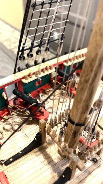
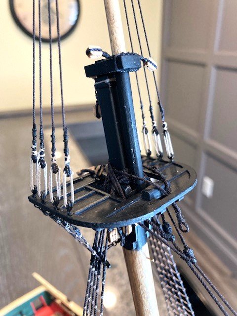
Completed the Main Mast shrouds a la the Fore Mast shrouds. Added the sheer poles (3/64”x1/32”) and the Fairlead Bars 1/32”x3/64”) to the shrouds. Painted them black to match the replica ship. I glued them first and then lashed them to the shrouds using .012” line. I drilled three holes in the Fairlead Bar as detailed on Sheet 5. Before drilling the holes, I added a little CA to prevent the wood from splitting. I made a tick mark for each hole on both sides of the bar and them drilled the holes from each side. The holes are for the “lines going to the pin rail.” The only line that I can find on the Sheet 5 is the Top Mast Tack. Note: After looking at photos of the replica ship, I discovered that the Fairlead Bars are lashed to the shrouds on the inboard side and not the outboard side as I did – I wish I would have read 6ohiocav build log before fashioning the Fairlead Bars. Also, as can be seen on the attached photo of the replica ship, there are eight (8) lines that pass through the Fairlead Bar. Further, there is a Fairlead Bar on the Main Mast shrouds as well (not shown on Sheet 5). This is a shorter bar that has five (5) lines passing through it (see photo). Decided to leave the starboard side fair lead bar in place for risk of damaging the shrouds while trying to remove it. Lashed the port side fairlead bar to the inboard side of the shrouds. Pre-drilled holes in the bar via the same method as the starboard side. Fashioned the Main Mast Fairlead Bars. Pre-drilled 5 holes in the Fairlead Bar and spray painted them black. Glued the bars to the shrouds and lashed them with .012” line. Note: the bars are shorter than and lashed on the shrouds lower than the Fore Mast Fairlead Bars per the replica ship. Touched up the shine from the CA with brushed on black paint. Added the staves to the shrouds. The plan calls for 1/32 inch diameter wood staves. The kit is not furnished with this size wood strip. I used a 1/32“x 3/64“ wood strip. The staves are mounted on the inboard side of the shrouds, which makes them difficult to install. I applied CA to the shrouds to secure the staves. I then lashed the first stave to the shrouds with .008 inch line. I decide not to lash the remaining staves. My thought was that the staves will be secured when the upper mast shrouds are wrapped around the staves. Note: I extended the staves across all of the lower shrouds. Sheet 5 shows the staves extending only across the four aft-most shrouds. Next, the catharpins on the lower shrouds. It’s easier to add them before adding the futtock shrouds. Note: There is no discussion in the Instruction Manual on when best to add the catharpins. The detail on Sheet 5 calls for the catharpins to be made with .023” rope. I used a .018 rope – I think thinner is better than thicker in this case. I made 2 thimbles for each catharpin from 28 gauge wire and lashed a short piece of .018” rope to each thimble. The completed piece measures about ¾” from thimble to thimble. Next, I cut a length of .018” rope long enough to pass through one thimble and the shrouds. I eye spliced and seized one end of the rope to the stave, passed the other end through the thimble and then through the shrouds and attached an alligator clip to the end. I cut a similar length of rope and passed it through the opposite end thimble and through the shrouds, and clipped both ends together with an alligator clip. The loose end of the eye spliced rope was eye spliced and seized to the stave. I adjusted the length by tensioning the loose ends of the rope on the opposite of the catharpin. The opposite side catharpin was set in a similar fashion. The sides of the catharpin aren’t exactly equal, but they’re close enough for my liking. Added the 16 futtock shrouds. The shroud hooks were 5mm purchased from Crafty Sailor (easier than making them), blackened with Brass Black. The plans call for .023” rope (not furnished with the kit) for the futtocks shrouds. I used Syren .023” rope. I found that a length of 2.5" is sufficient The lines were seized to the hooks, hooked onto the deadeye eyebolts, wrapped around the stave, and seized to the lower shrouds with polyester sewing thread as per Figure 8-3 in the Instruction Manual. The shrouds were fairly easy to install. I’m thinking of fashioning the Main Mast Stays next.

.jpg.ebb24394dc234287f6198551fb212248.jpg)
.jpg.ce23cbeebb116e3c31ca9a6858aabc71.jpg)
.jpg.c1aac5fcd6ccf4ceba6d9bbce852e418.jpg)
.jpg.07a23ae41f493d0ef89d1d8defe6abc4.jpg)
.jpg.94bfafb31391fcf23241a9748a057767.jpg)
.jpg.95f0745639d1620b1e89526517e5e2fa.jpg)
.jpg.a430dfd280a5f7a0fcaf676bc5abff67.jpg)
.jpg.4ece2affa698124cb91ccbb0dbaf8e39.jpg)
.jpg.0020f07320f2795ed73f5ca0b1aad842.jpg)
.jpg.dcd468fbb341fc07918469de43c013c0.jpg)
.jpg.e0c3fd962daeba10d5ed52cacfbbadb8.jpg)
-
Perseverance and patience are virtues in model ship building. Thanks for the compliment. I'm pleased that my build log is helpful.
-
My objective is to simulate the current ship yet not historically authenticate it. Thanks for the compliment.
-
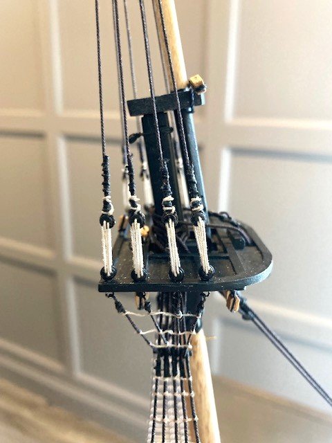
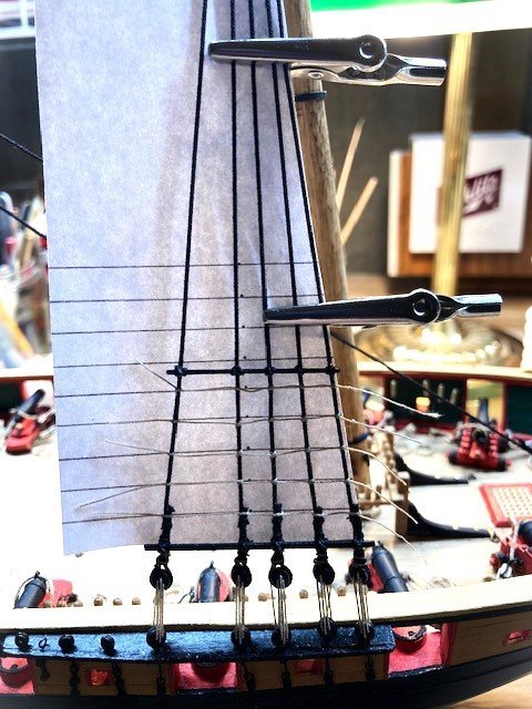
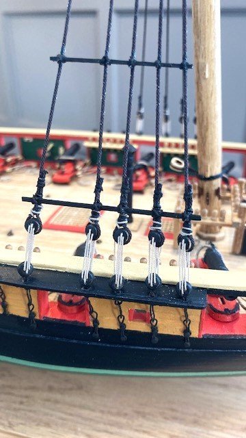
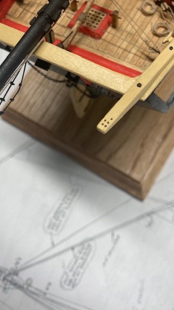
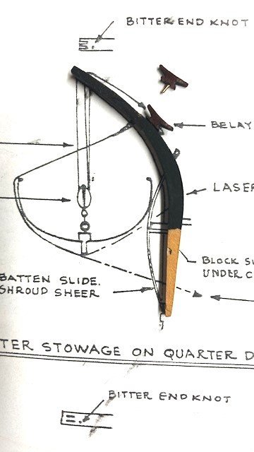
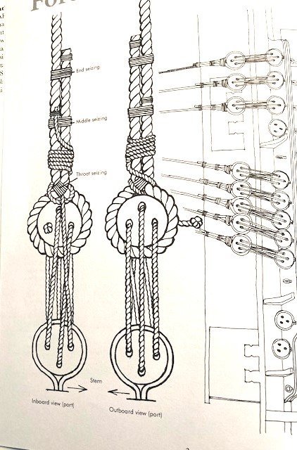
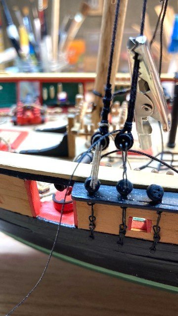
Decided to forgo the hammock stanchions. I thought the effort wasn’t worth the effect. I like the clean look without them. So, on to rigging the Main and Fore Mast lower shrouds. But, first, I discovered that I had forgotten to attach the boarding ladders which I had previously fashioned. The ladders interfere with the carronade tackles. It must have been problematic on the actual ship. And I decided to finish the laser cut quarter davits. I painted them yellow (MS4829 Hull Yellow Occre) and black (Model Color acrylic by Vallejo). The davits have sheaves at the top. I created the faux sheaves in the davits using a saw. Drilled a .55mm hole for the bitter end knot. Added a 7/32” cleat to each davit per the detail on sheet 4. I purchased the cleats from Crafty Sailor. To secure the cleats to the davits I inserted a brass pin in each cleat. Note: be careful when making the davits because they are not uniform in shape from end to end. Lay them on the detail on sheet 4 to be sure you have the correct orientation. I made the davit brackets from 1/64"x1/32" brass strip - they will be blackened later. The davits will be left off ship and out of harm sway for now. While fabricating the davits, I realized that I did not drill a hole in the stern davits for the bitter end knot. This was carefully done with a .55mm drill. Before making the shrouds, I reviewed the plans and the instruction manual, particularly the details on Sheet 5. I began with the Fore Mast lower shrouds. The burton pendants with single shroud P&S are first, followed by the first pair of shrouds P&S and, lastly, the second pair of shrouds P&S. The fore stay, preventer stay, and course yard sling in that order. As the instruction manual states “remember, stays go over the shrouds.” The plan calls for the shrouds to be .035” line (not furnished with the kit). I used .035” brown rope purchased from Syren. I spray painted the deadeyes flat black (Testors 1249T enamel) to simulate the actual ship. I made the burton pendent shrouds first following the detail on Sheet 5. I measured the length of the shrouds from the plan and allowed enough wrap around the 1/8” deadeyes. The 1st and 2nd pair the shrouds are slightly longer from fore and aft. I found a rope length of 19" to be adequate. I added a little CA to the ends of the rope to prevent them from fraying. To space the deadeyes, I fashioned a jig from 28-gauge wire as pictured in Figure 8-2 in the Instruction Manual. With the jig in-place, I wrapped the first shroud around the deadeye, tensioned it, attached an allegator clamp, and seized it with .012” black rope at the throat, middle, and end of the rope. The length of the end of rope is a matter of preference. I made it 1/2" above the top of the deadeye. I used Syren 012” rope for the lanyards. I found that I had to adjust the height of the jig for the second pair of shrouds in order for the deadeyes to line up. There isn’t much detail on the plans to illustrate rigging the deadeyes, so I copied a nice detail from Petersson’s Rigging Period Ship Models and added it to the build log (see photo). I didn’t quite follow the detail in every respect, though - I improvised. Completed the Fore Mast lower shrouds. Next up, the Main Mast shrouds. This will be the last post for 2023. Wishing everyone happy holidays and a healthy 2024. Stay tuned.
.jpg.538347943d4e35ce4aa53cc00c1fe68c.jpg)
.jpg.049065de4024872b12930787939d2e27.jpg)
.jpg.81516dd8ac7d51f30811e15ddcf9c3fc.jpg)
.jpg.e8cacb0760a69726e523f5b1bdd25e1f.jpg)
.jpg.28d36edf6c54d938a44dbb1c2b5d4bd5.jpg)
.jpg.76a50725e731b51d4d7626dc391991de.jpg)
.jpg.685f05d4a9b8e183d6252b561e4ddc02.jpg)
-
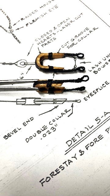
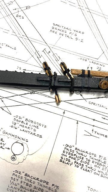
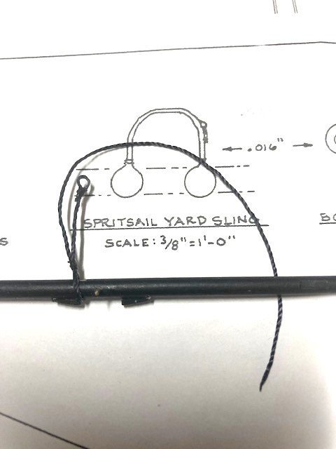
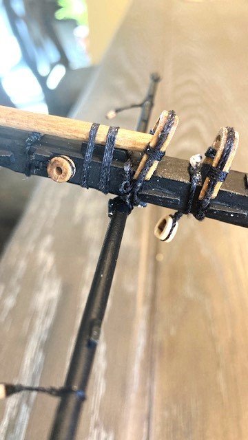
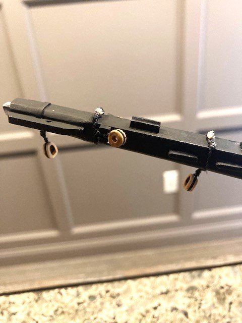
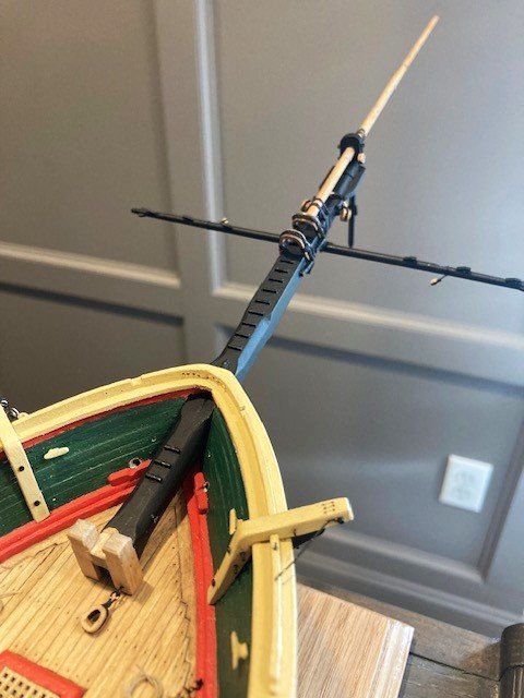
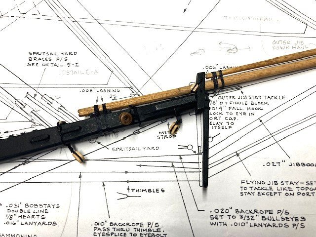
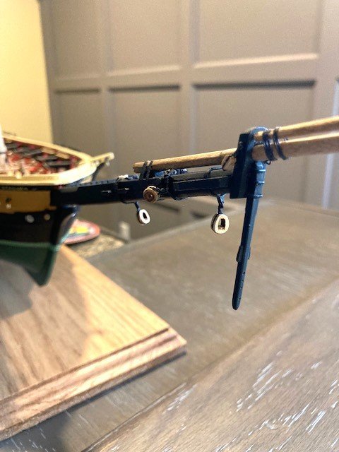
Completed placing the structures and setting the Main and Fore Masts. Decided to work on the Bowsprit next. Added the following blocks to the Bowsprit cap: 1/8” double with hook on front port side for Jib Stay tackle, 3/32” single with hook and thimble on lower eyebolt P&S for Sprit Sail yard lifts, and 1/8” single on upper eyebolt port side for Jib Boom out haul tackle. Note: Unable to find on the plans where the outhaul tackle is belayed. Looking at other build logs, I found that the outhaul apparently passes through the chock rail and is belayed to the Bow Pin Rail. Added a Syren 1/8” closed heart (not furnished with kit) to the metal strop on the Bowsprit for the Bob Stay. Will use .012 tan rope for the lanyard and Syren .025 black rope for the Bob Stay. Made the Bowsprit Collar (.021 black) with 1/8” bullseyes and mounted it on the Bowsprit for the Bowsprit Shrouds. Will use .012 tan rope for the lanyards and Syren .025 black rope for the shrouds. Bullseyes were purchased from Model Expo – not furnished with kit. Fashioned the Inner Bobstay Collar (.021 black) with 1/8" closed heart as detailed on Sheet 5. Lashed the Jib Boom to the Bow Sprit and the Flying Jib Boom to the Jib Boom. I used the kit furnished .008” rope. Next, I turned my attention to the two laser cut Hearts for the Bowsprit Forestay and Fore Preventer as shown in Detail 5A. The Hearts are rather thin and fragile. I snapped one while sanding of the char. So, use caution when sanding and creating the groove in them. The hearts are black on the replica ship but, like many other build logs, I decided to stain them (Golden Oak). Added the double collars for the Forestay & Fore Preventer Stay as per Detail 5-A. The detail calls for .023” rope for the collars, which is not furnished with the kit. I used the kit supplied .021” rope. I made the collars 2” long from eye spice to eye splice. The collars were lashed under the Bowsprit with .008” tan rope. Note: The Instruction Manual, page 28 calls for using .031” line for “Lines of plan” .022” to .031” - .031” line is not furnished with the kit. Moved on to the Spritsail Yard sling. The detail on Sheet 5 calls for .016” rope which is not furnished with the kit, so I used .021” rope. One end of the sling has to be attached to the Spritsail Yard and the opposite end has to be wrapped around the Bow Sprit and then around the Spritsail. I’m going to remove the Bowsprit while I work on the Hammock stanchions and rails next, for fair of snagging it.
.jpg.bbd96bfff23a334d5402e305c0588344.jpg)
.jpg.869e260d99fb29b792a40a624a04a86c.jpg)
.jpg.12c3d62a1afe7f3eb6a5a09a30a4246f.jpg)
.jpg.0e8266c658ff9845f7efe2b358c9bb97.jpg)
.jpg.b6ae4aa95ebf6ef502a6e20960d28aa1.jpg)
-
Looking good.