
HOLIDAY DONATION DRIVE - SUPPORT MSW - DO YOUR PART TO KEEP THIS GREAT FORUM GOING! (83 donations so far out of 49,000 members - C'mon guys!)
×

abelson
-
Posts
467 -
Joined
-
Last visited
Content Type
Profiles
Forums
Gallery
Events
Everything posted by abelson
-
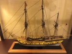
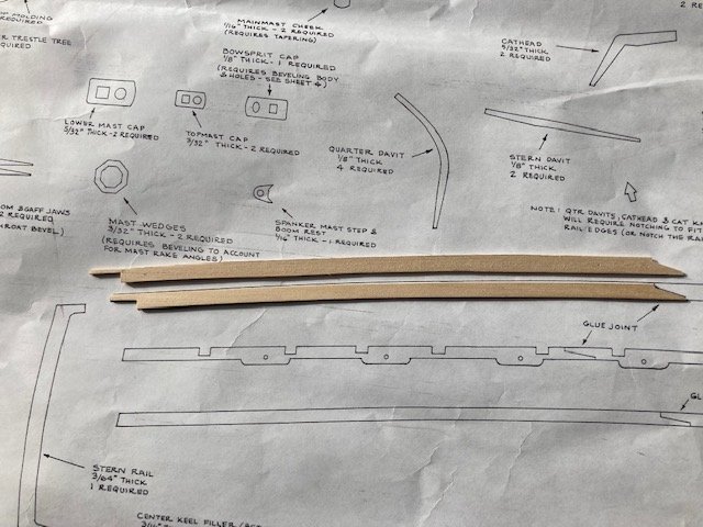
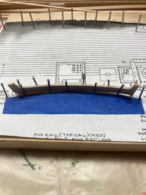
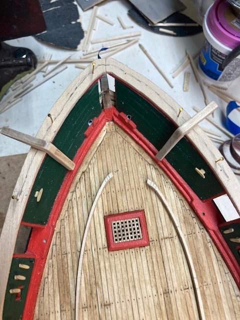
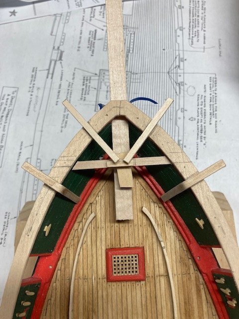
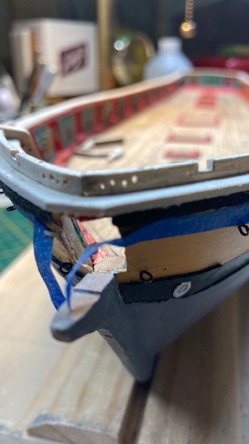
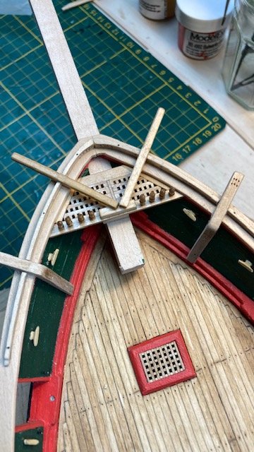
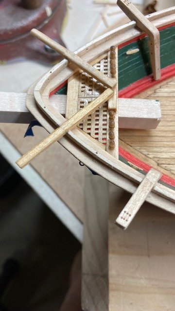
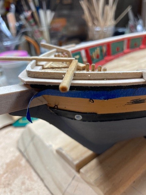
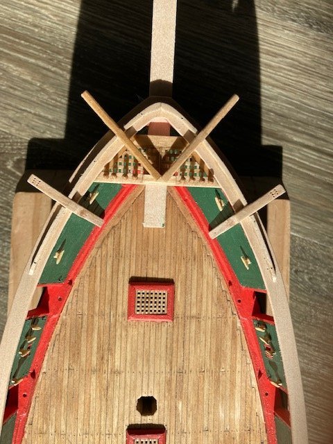
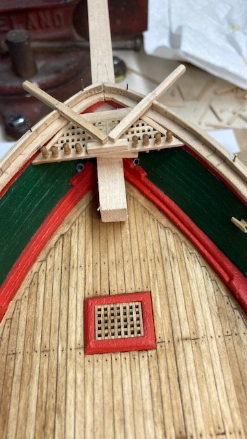
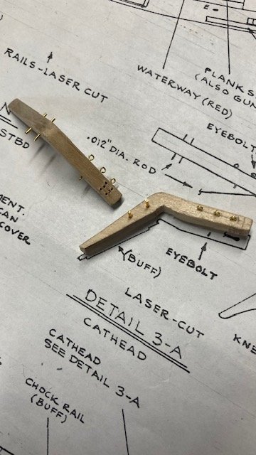
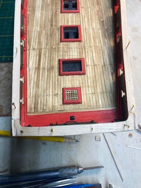
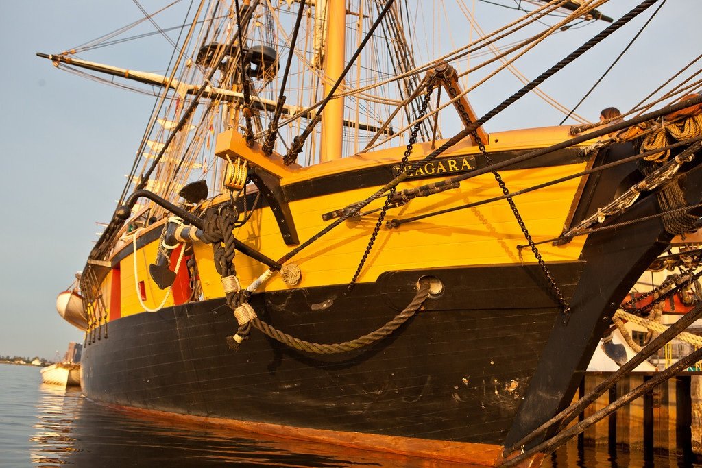
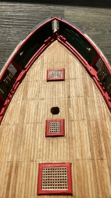
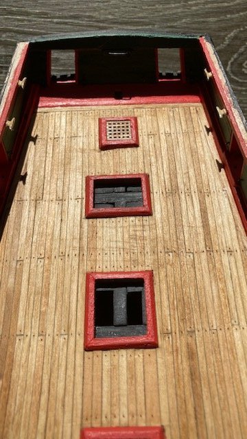
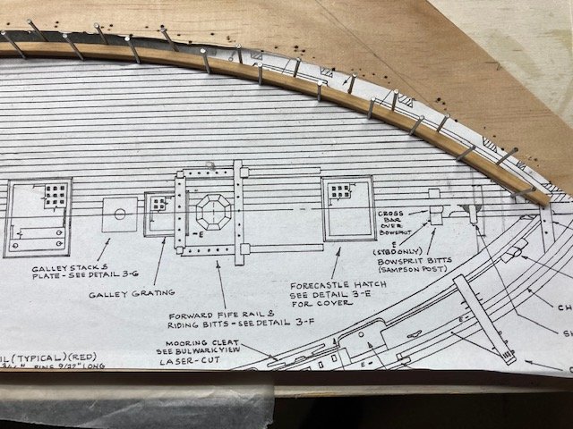
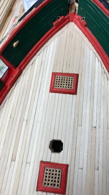
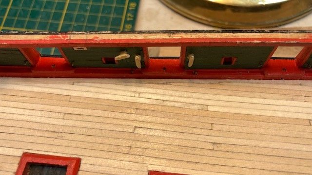
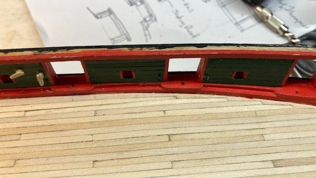
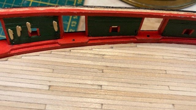
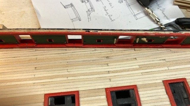
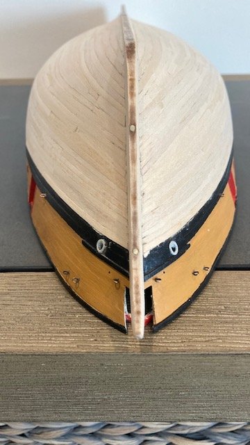
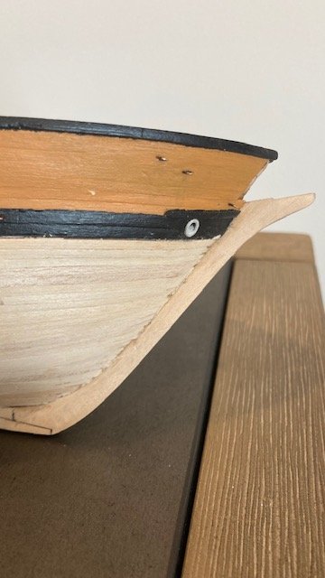
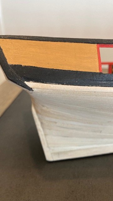
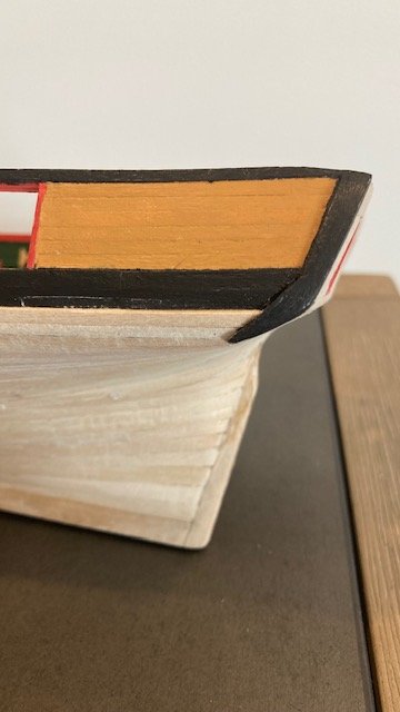
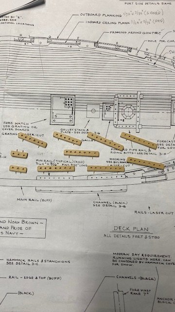
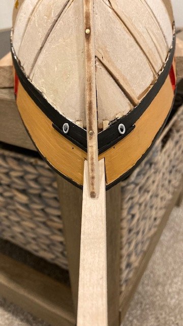
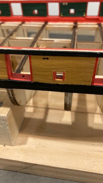
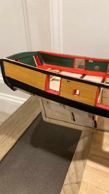
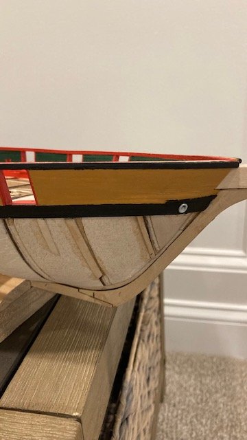
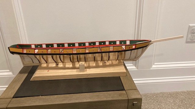
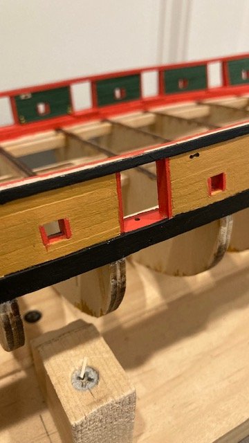
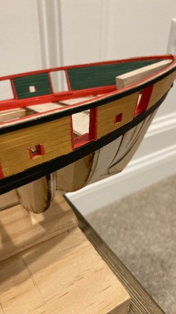
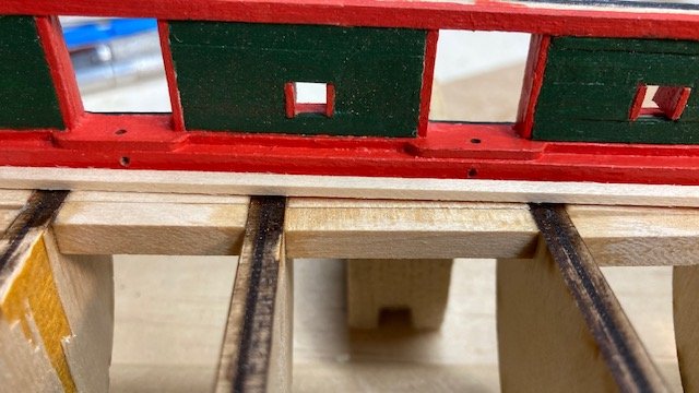
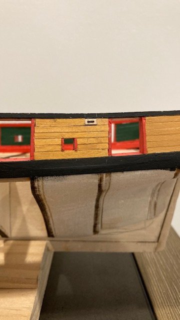
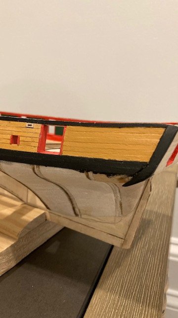
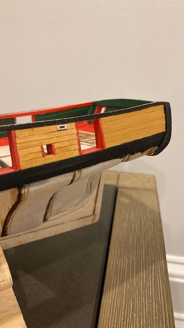
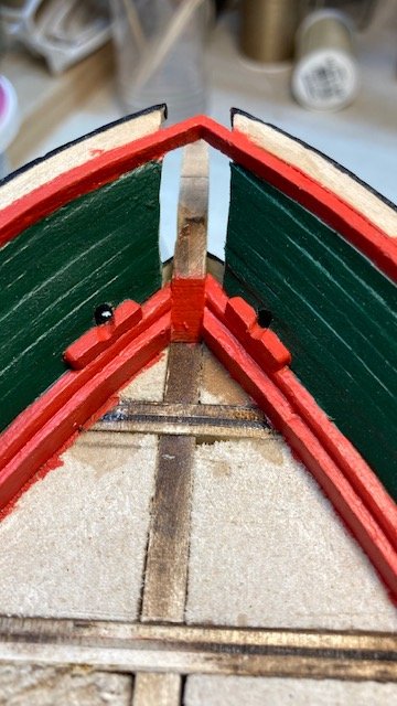
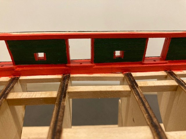
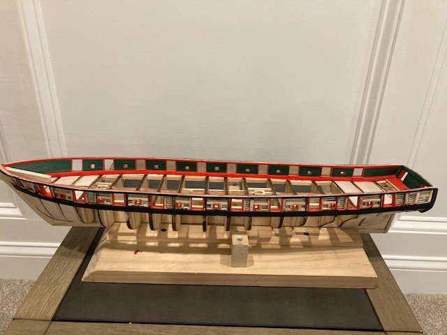
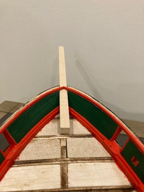
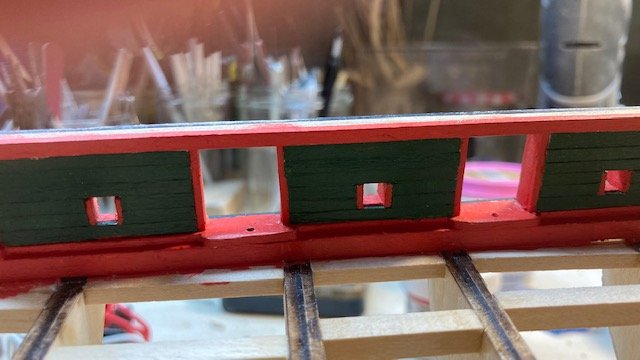
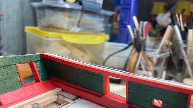
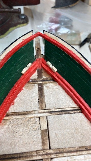
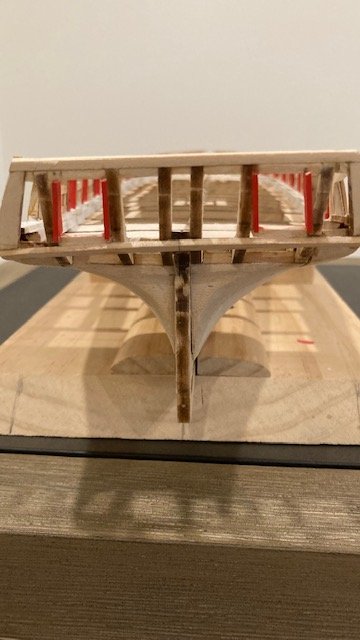
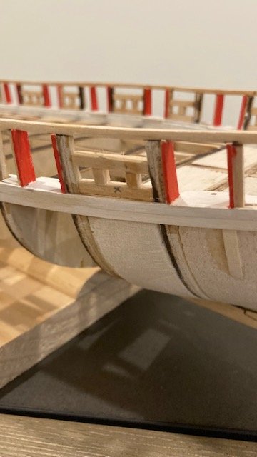
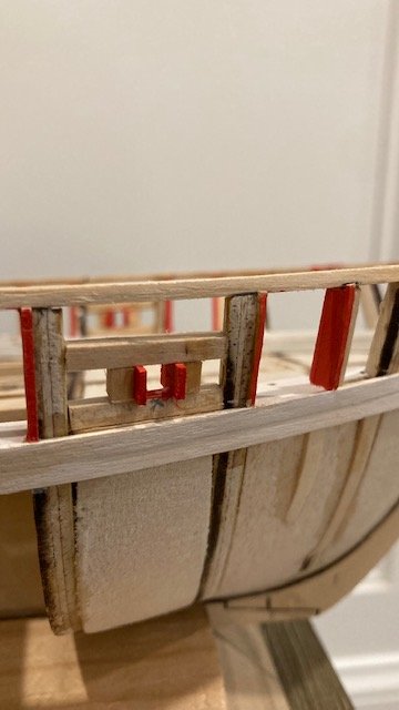
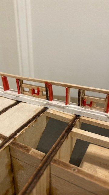
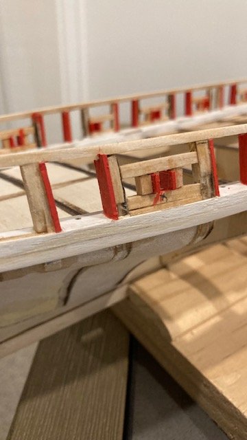
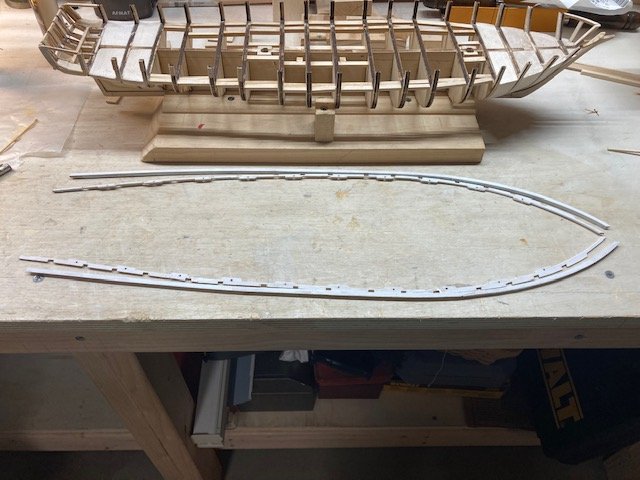
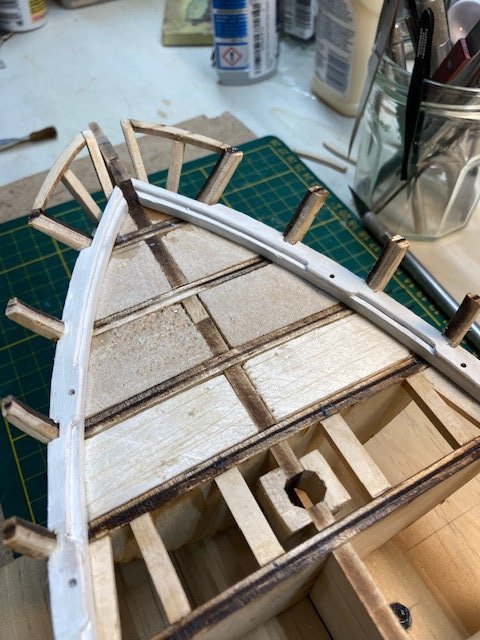
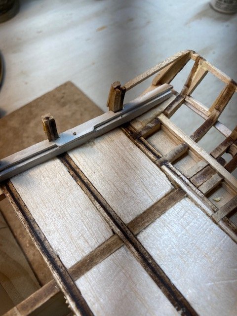
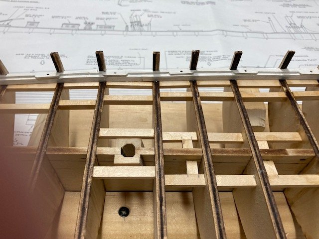
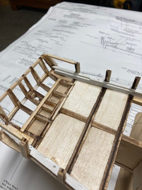
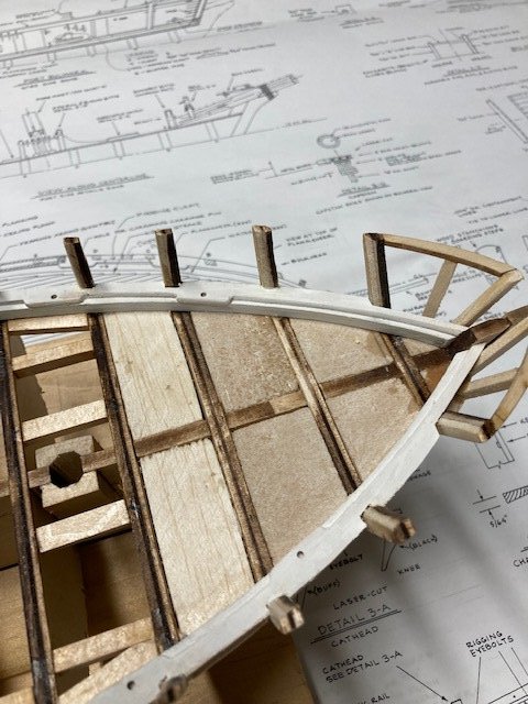
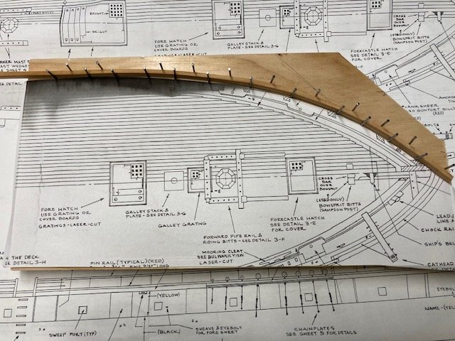
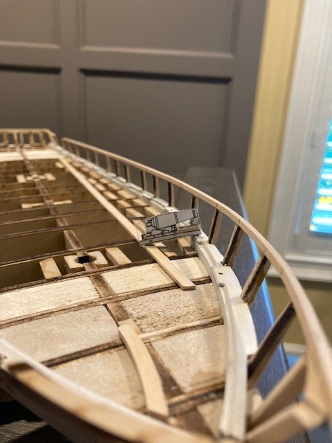
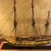 Working on the main rail. I had to fabricate some pieces from 1/16” basswood. The laser cut bow pieces didn’t provide enough overhang and, as other build logs have noted, the laser cut stern pieces are too short. The laser cut stern rail didn’t provide enough overhang for my liking, so I fabricated that too. I made a jig for the stern rail. I soaked the stern rail in water and then set it in a jig until the wood dried. I rough-fit all the pieces before permanently attaching them. I used brass pins to temporarily secure the rail pieces. The nails allowed me to set the rails in the exact location when it came time to glue them in-place. I worked from bow to stern. After gluing the rails, I removed the nails and filled the holes with putty. I realized that it doesn’t matter if the stern rail joints don’t fit tightly because the joints will be covered by the davits. Moving on, I removed the laser cut chock rails, removed the laser burn, and tapered them as per the plans. I added a little detail to the end of the rails based on the photo I found of the Niagara ship (see photo). The chock rails have rigging line holes in them (6 on each side). At the bow, there are 3 Fairlead holes for the Downhauls and Sprit Sail Lifts. The holes need to be big enough to pass a .010 line. I pre-drilled the holes with .55mm bit first and then enlarged them to pass the .010 line. The chock rails need to be cut out for the catheads. This reminded me that the ship had boomkins (also called bumpkins) forward of the catheads (see photos). These are not shown on the plans. I discovered this while reviewing cdrun89 build log. The boomkins are tie-offs for the fore tack lines. The photo also shows the fairlead holes in the chock rail. There is also a pin rail at the bow. I decided to add the boomkins as they appear in the photos. I drew two sketches based on my interpretation of the photos. The first sketch shows the grating arrangement at the bow. The second sketch shows the boomkins superimposed on the first sketch (see photos). From the Niagara photos, the boomkins appear to be slightly longer and thinner than the catheads, tapered and chamfered from the chock rail inward, and have an octagonal shape from the chock rail outboard. Subsequently, I found another Niagara photo from greatgalleons build log that better depicts the boomkins. Note the chains attached to the hull and the boomkin to secure it from lifting. The angle of the boomkins was "quesstimated" from the overhead photo of the ship. I fabricated the boomkins from 3/64”x1/8” strip, the grating from 1.3”x 3/64” grating purchased from Model Shipways, and the pin rail from 3/64”x 1/16” strip. I made a frame for the boomkin grating based on the sketches. I set the gratings edge to edge and made two sections. Each section was trimmed to fit in the frame. I applied CA on the backside of the frame to secure the grating. It came out basically as I envisioned it. For the frame, I used scrap pieces of the main rail. The entire structure can be inserted in the bow beneath the main rail. I still need to make another grate section at the bow. Note: In the photo, there are 5 belaying pins on each side of the boomkins. The plans show only 3 holes per side for belaying pins. I couldn’t fit 5 holes so I only made 4. I Pinned the chock rail to the main rail temporarily. I marked the location of the boomkins on the chock rail. The boomkins don’t rest on the main rail, so I made a notch in the chock rail accordingly. Finished coated the boomkin grating and pin rail and the boomkins with Minwax Tung Oil. I’m undecided as to whether to anchor the boomkins with iron straps. For now, I’m going to leave the boomkins and grating structure off ship. Added an extra cleat for the fore tack. The catheads are next. I marked the location of the cat heads on the chock rail. The cat heads sit on the main rail. Before cutting out the chock rail, I permanently secured the chock rails to the main rail with white glue. I made the faux sheaves in the catheads and drilled holes for the eye bolts and rods. I had to file and notch the catheads to fit them to the main rail. they'll be installed later along with the cathead knees. One item of note, the Deck Plan on Sheet 3 shows a 1/16”x1/16” anchor chafing block on top of the main rail. In reviewing some other build logs, , I notice many omitted the anchor chafing block. I cut the pieces, but I'm not sure if I will add them. Next up, marking the waterline and painting the hull. Stay tuned.
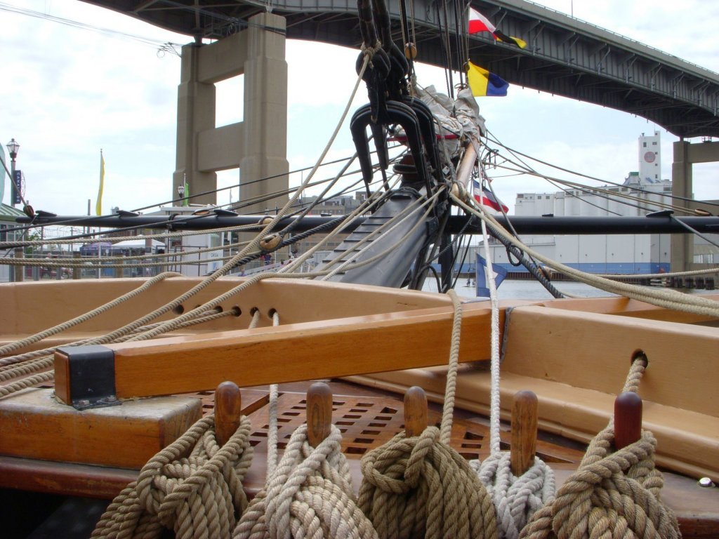
.thumb.jpg.156b9862483c332c96ff9d44b20274ad.jpg)
.jpg.5919d68c74ba8aac42da55c3742e34ae.jpg)
.jpg.a858e546e677af273e2c96ca52e05c30.jpg)
.jpg.be5c5f04fa1f72ff3f2f91e120da23d4.jpg)
.jpg.9cb090ec12fba1ed88679d4ac676f422.jpg)
.jpg.fd3ffe7609531fc2d2484d92eaab801a.jpg)
.jpg.32fb0c1bc94dac5e54416ad63f76f7a6.jpg)
.jpg.5165abd5847cc9a883a864190fc0dc39.jpg)
.jpg.5df90ec0bb8f2bc7ebc85cd72c7fd3fc.jpg)
-
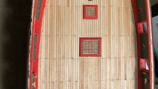
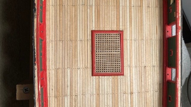
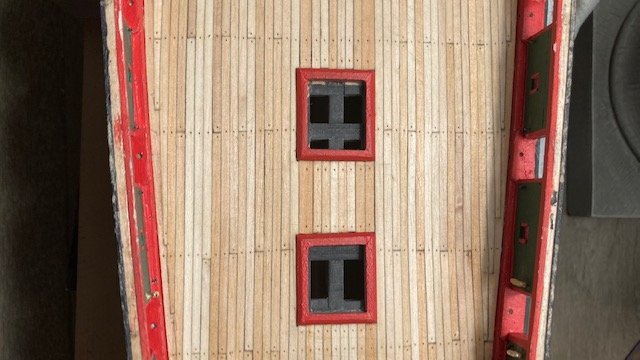
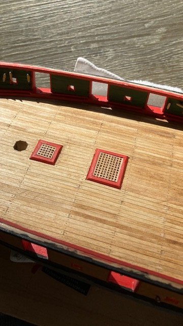
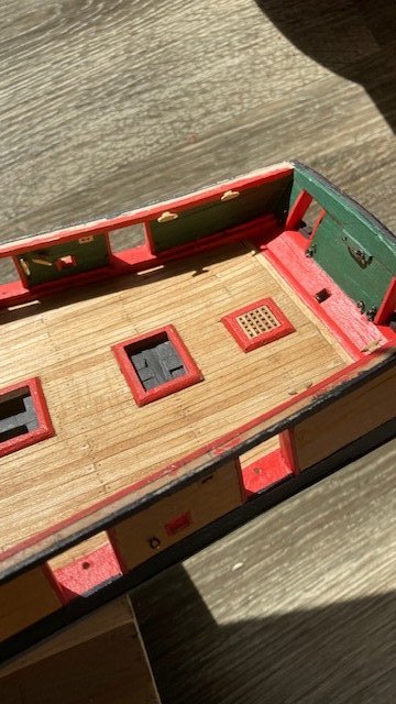
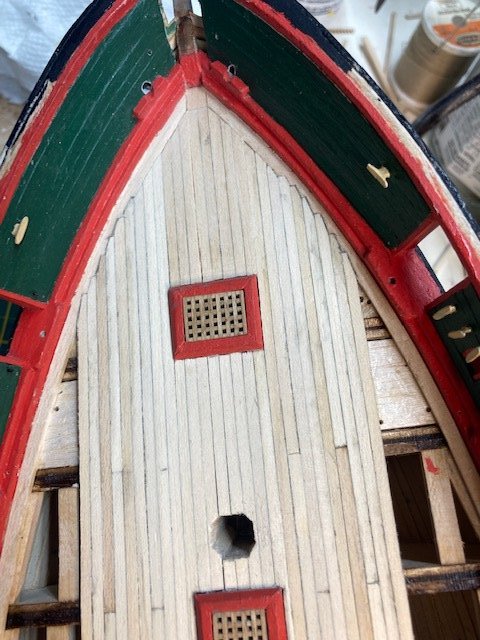
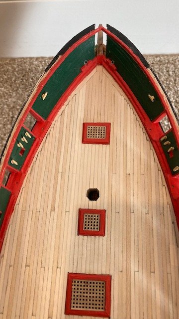
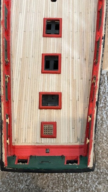
Finished the tree nails. Used a .55 mm drill bit. Broke quite number of bits - they’re very thin. Fortunately, I had enough to finish. Sanded the deck some more and finished it up with fine steel wool. Redrilled all the tree nails to clean them out. In the process, I discovered a few that I had missed. Contemplated whether to fill the treenails with putty. Decide to do a test strip where I drilled some holes and applied Golden Oak stain to see how the treenails look sans putty. I liked the look, so I decided to forego the arduous task of filling the treenails. With that, I wiped the deck with a tack cloth and applied some Minwax Pre-Stain Wood Conditioner. The Pre-stain accentuates the treenails as well as the variations in color of the planks (see following photos). Next, I applied one coat of Minwax Golden Oak stain. Even with the wood conditioner, I think the deck is a little splotchy. The stain shows some the sanding marks, but I think that it gives character to the deck. I’m satisfied with the results (see photos). I want to keep the deck light, so I won't be applying a second coat of stain. I'm thinking about applying a sealer to the deck, though. Next up, the main rail.
-
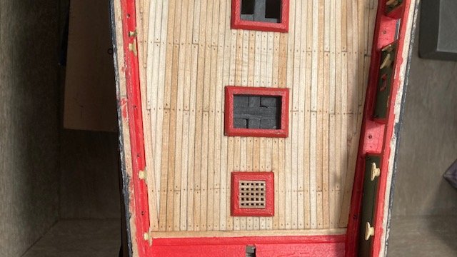
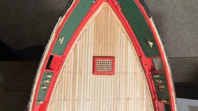
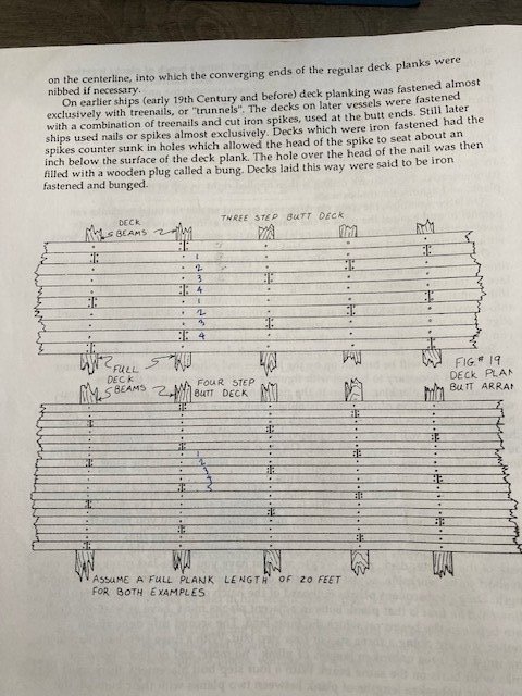
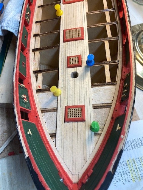
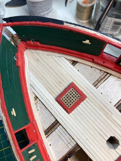
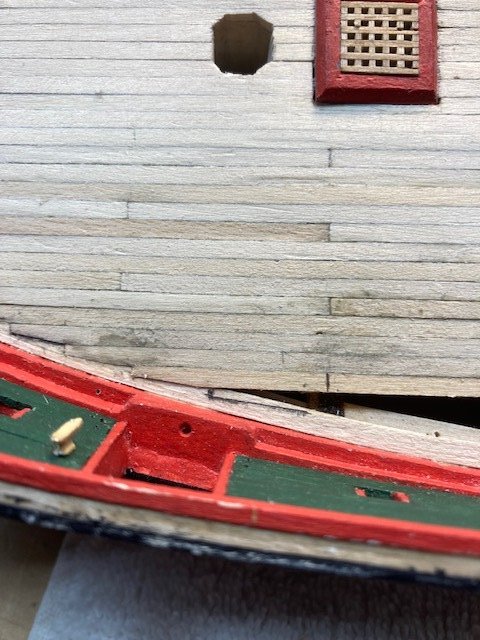
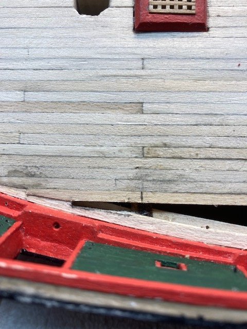
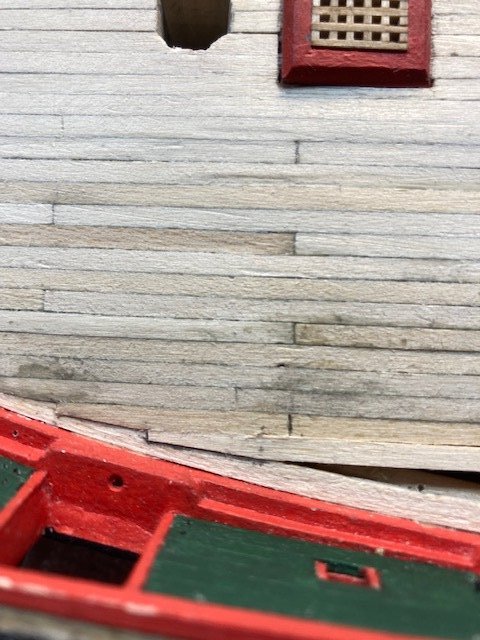
Since the last progress report, I completed planking the deck. As I stated earlier, I used the “shipwright practice” where the decking is installed around the coamings. I began with the nibbing strake. I used 1/8”x 1/16” strips. I soaked them in water overnight and then put them in the jig I used to bend the hull planks. While waiting for the strips to dry, I decided to do some research on planking the deck. No matter how many ships you build, it’s still helpful to review “how to” publications on planking. I revisited the deck planking section of Planking the Built-up Ship Model by Jim Roberts to refresh my memory. It reminded me that figuring out placement of plank butts is not necessary until you reach the outer edges of hatch coamings. Planks are butted in either a “three step” or “four step” configuration. The instruction manual does not discuss this. I prefer the “three step” configuration where there are three unbroken planks between each plank butt on the same beam (see photo). The length of plank between butts is typically not more than 20 feet at the plan scale. However, try as I may, the “three step” configuration became a two step in some places – it’s easy to lose track of the butts. Anyway, going forward, I removed the margin plank (nibbing strake) from the jig. Cut down a strip of 1/16”x 1/4” to fit between the two margin planks at the bow. Glued the margin planks in-place with yellow glue and used push pins to secure them. Applied a little CA at the beams. The nice thing about CA is that it flows nicely between the joints. Completed seven planks on each side of the deck centerline. The next seven planks are nibbled at the bow. Also, butt joints begin along planks. The coamings align with the planks fairly well. In some places I had to use a slightly wider plank to even out the planks. I don’t think the wider planks will be noticeable whence the deck structures are all in-place. I shaded one edge of the planks with #2 pencil to simulate caulking between joints. The instruction manual says the planks taper from midship aft and parallel with the waterway. Based on the plans, the planks begin to taper at the midship aft 6 planks away from the centerline. The are 20 planks on each side that need to taper from 6” down to 3” at the end plank. I decided not to follow the instruction manual and will nib the planks instead. For the nibbed planks. I made a tick mark about 1/32” wide on the end of the plank and aligned the plank with the nibbing strake to determine the angle of the nib. I cut out the nib, aligned the plank with the nibbing strake again, and traced the nib on the strake with a pencil. I cut the nib out with an x-acto knife. I most cases, the nib was not an exact fit and needed to be trimmed and filed/sand. I used each subsequent nibbed plank as a template for the opposite side of the deck. This made the port and starboard side nibbed planks fairly uniform. The planking brings to light the undulations in the deck, so a lot of sanding was required to even them out. As it stands now, the deck has been fine sanded and is ready for treenails. Here are a bunch of photos. Stay tuned for work on the treenails.
.jpg.0e2dc8c10076f8f4f6b0f5cbe73feebb.jpg)
.jpg.cf7622e9fc33679237cdf84a35287e1b.jpg)
.jpg.8038f0a18d4322a17b0d6094089b8071.jpg)
.jpg.4214fcba84a56cdafa9605ca40567774.jpg)
-
Thank you!
-
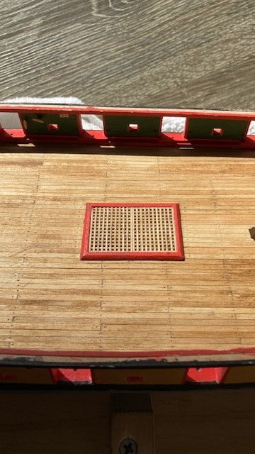
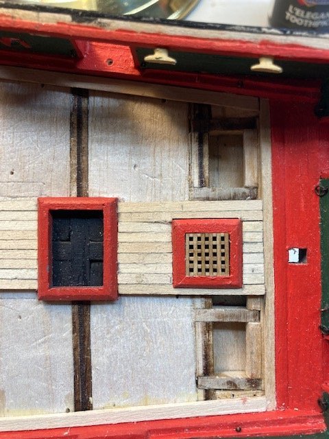
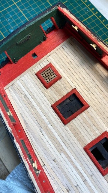
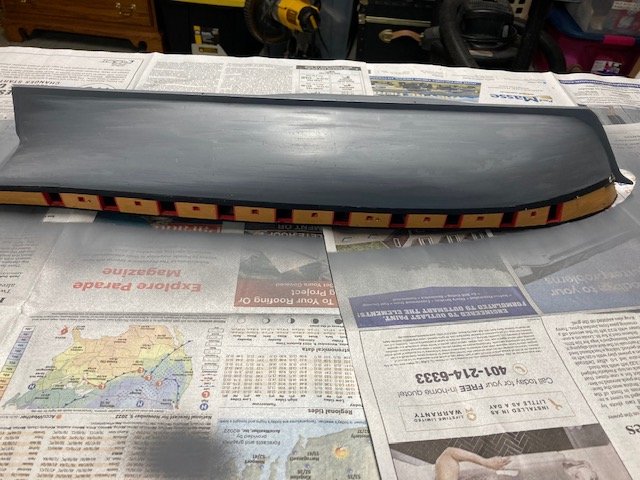
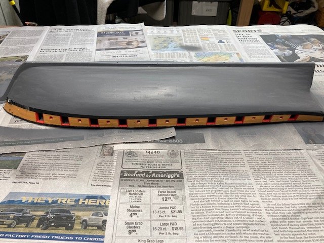
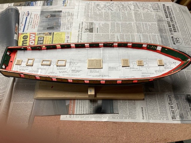
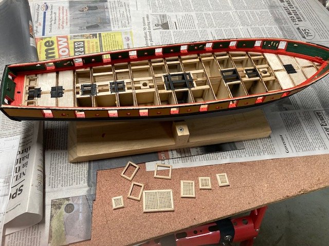
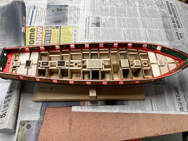
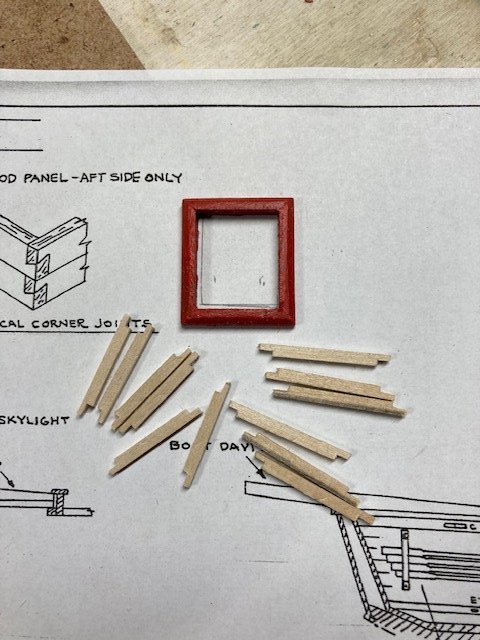
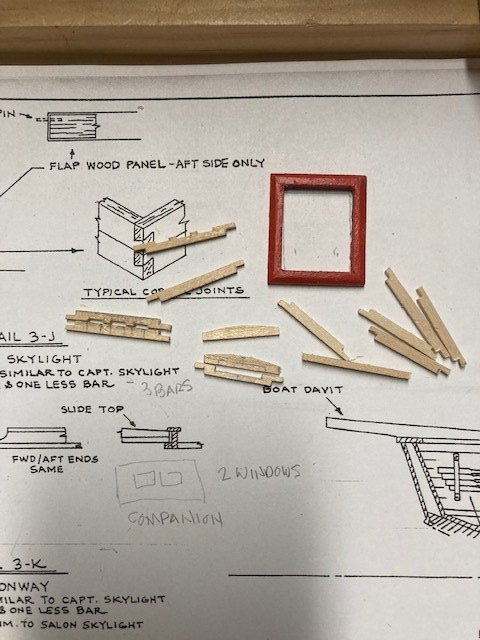
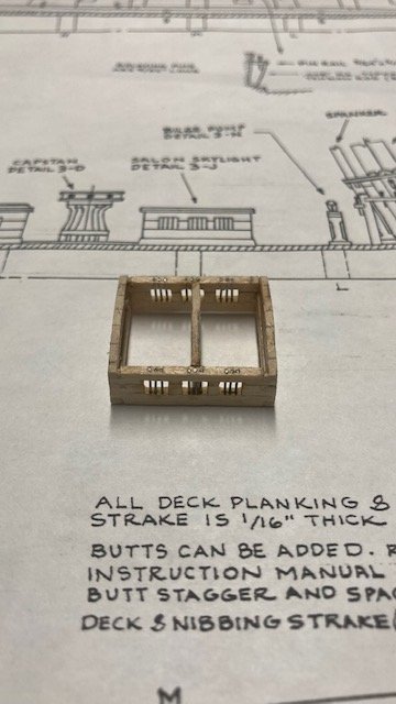
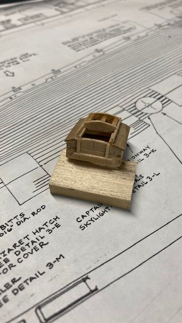
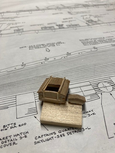
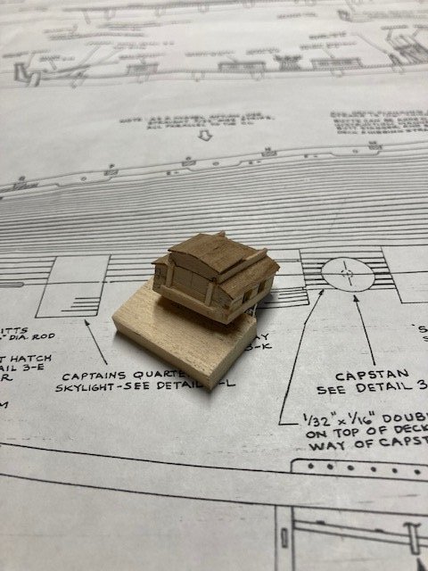
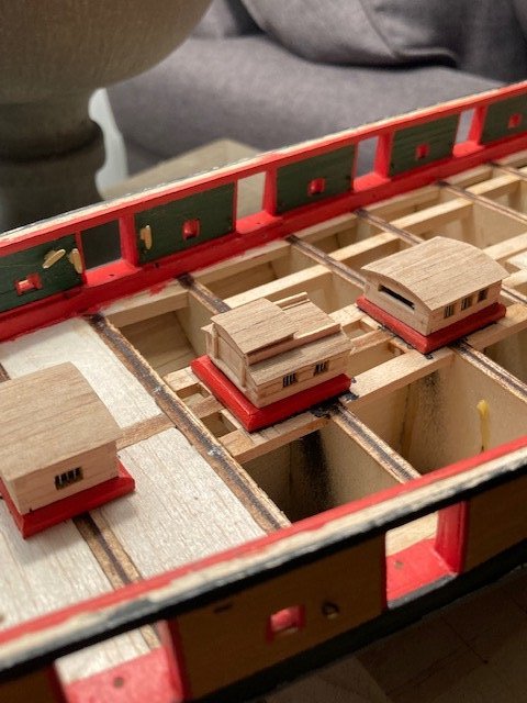
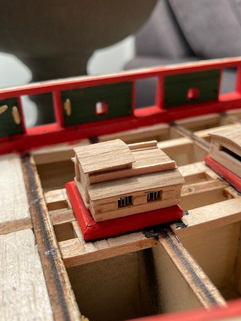
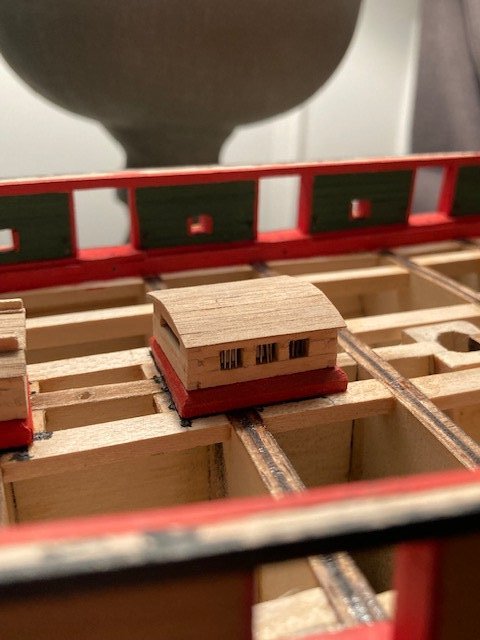
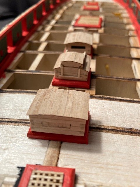
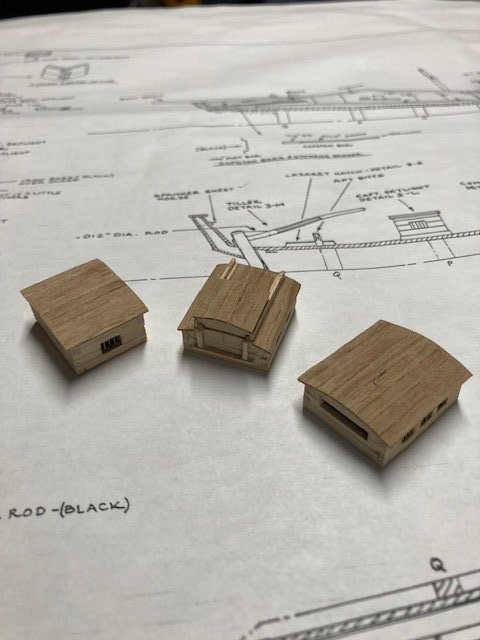
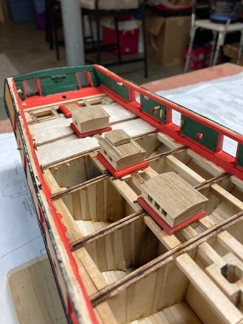
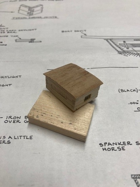
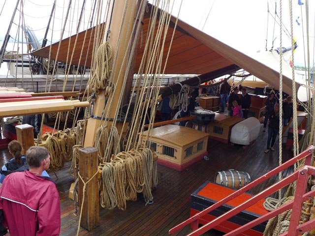
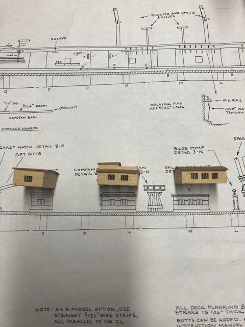
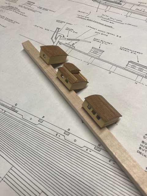
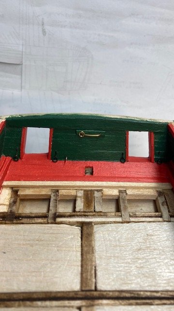
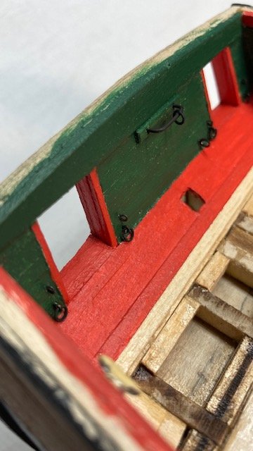
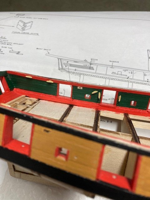
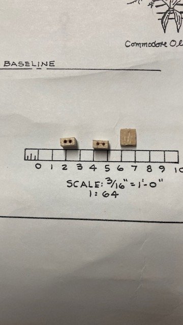
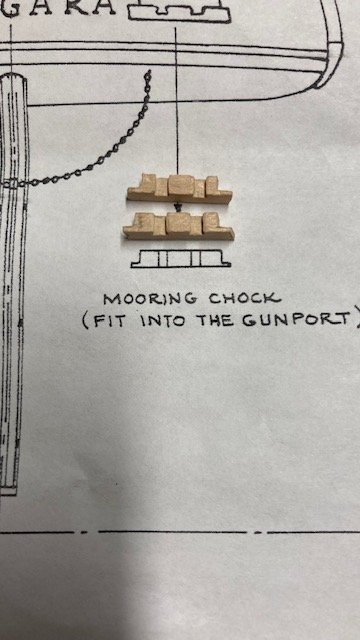
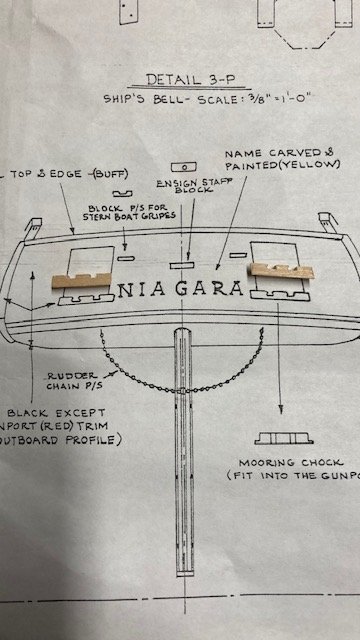
Since the last update, I’ve made some major progress. I added some wood filler, sanded and re-primed the hull. The hull is not perfect, but that’s not what I was aiming for. I did some light final sanding in preparation for final painting, which will be done later. Added the stern ensign staff block, stern boat grips, and mooring chocks before painting the transom. Started thinking about planking the deck. The instruction manual says “shipwright practice” is to glue the coamings to the bulkheads and to plank around them. In reviewing several build logs, all of them installed the coamings on top of the deck, which is the “alternative method” in the manual. Before deciding which approach to take, I started looking at the coaming details on Sheet 3. Note: The details are 3/8” scale. The coamings are noted as 9/64” x 5/64” and are tapered. I have found that many build logs do not taper the coamings – I stuck with the plan details. I used 1/8”x 1/8” strips. The strips need to be tapered to 1/16” at the top and at the bottom if using the “shipwright practice. If using the “alternative method” the coamings have to be reduced in height by 1/16”. To make the taper, I laid a 1/16” strip adjacent to the 1/8”x 1/8” strip and scribed a pencil line along it. I repeated the process to get the bottom taper line. I don’t have a small plane, so I removed some of the taper with an x-acto knife and then filed/sanded the taper down to the pencil lines. I made the coamings as if I were going to use the “shipwright practice.” I figured the added 1/16” height wouldn’t be that noticeable if the alternative approach is used. I mitered the coaming joints rather than using one of the joints detail in Fig 5-1 in the manual. I started with the Main Hatch. I decided to use grating rather than cover boards. After I had made the first coaming I realized that the grates should be made first and then match the coamings to the grating. Fortunately, the grating when assembled fit within the Main Hatch coaming. Note: I used ModelExpo grating MS2872 that I had left over from my Syren build rather than the cherry grating strips (MS0333) furnished with the kit (see comparison photo). I assembled the grating strips in an egg crate fashion. Going forward, for the Fore Castle Hatch, Galley Hatch, and Fore Hatch, I assembled the grates first and then made the coamings to match. The coamings were filed/sanded, primed, and finish-coated with Bulwarks Gun Red paint. The grates were stained with Golden Oak. I cut out the deck plan and used it as a template to locate the coamings. Thinking that I’ll use the” shipwright practice,” I painted the areas where the coamings will be placed flat black. Moving on to the skylights and companionway, I began with the Captains Quarter Skylight. As the Detail 3-L notes, this structure is a little taller than the others. I used 1/16” x 3/32” strips joined with corner joints. Note: The Captains Quarter Skylight windows have 4 bars and the Saloon Skylight and Companionway windows have 3 bars. I opted to make them all with 3 bars. Used .55mm bit to drill the holes for the window bars, and 28 gauge wire for the bars. The most difficult part of fashioning the structures is the windows, particularly getting the bars plumb. I drilled the holes down from the top edge through the bottom edge. Before drilling, I aligned the top edge with the bars on the plan and made a tick mark with a pencil at each bar location. Before drilling, I made a puncture mark at each tick mark with a sewing needle. This helped align the drill bit. If you keep the bit plumb, the holes will pretty much line up on the bottom edge. The Captains Quarter Skylight and the Saloon Skylight have a working flap panel that is pinned. The only way that I could figure out to insert the pin is to drill through the structure and insert a long pin that would go into the end of the flap. I didn’t see any value in having a working flap panel, so I opted for a faux panel. To simulate window glass, I cut a piece of plastic from the container that the fittings came in and glued on the back side of the window. For the roof, I used 3/16” x 1/32” walnut strips cut down to 3/32” wide. The walnut strips came from my Fair American build. They’re a nice contrast, so decided, rather to paint them, to apply Minwax Tung Oil. I painted the structures with one coat of ModelExpo MS4821 Deck Light House Buff. Note: I didn't provide windows in the aft side of the structures as the plans do not indicate that there are windows on the aft side and this was not obvious to me when I reviewed some other build logs. However, I subsequently discovered a photo from another build log that shows windows in the aft side of structures (see photo). Oh well. The Saloon Skylight was fashioned similar to the Captain’s Quarters Skylight except that it has two windows port and starboard. The Companionway structure was more challenging – it has three windows and a sliding top. A little ingenuity is required to fashion the sliding top (see photos). I’ve decided to use the “shipwright practice, so it’s on to the deck planking, starting with the nibbing plank. Stay tuned for more progress.
.jpg.1579fc95c2bf7cc18e127e8a2faf163a.jpg)
.jpg.4f19eb9e9a818838d5793e5b0dd46ad3.jpg)
.jpg.ae0243ef90ac9529722717844cfa1dc8.jpg)
.jpg.3ebca826742c3c77ff59d1d5cd288dcd.jpg)
.jpg.6ec52611ea1bd2b16deb46a024b7213b.jpg)
.jpg.5d9cdbcbed9dacdda3225ad92dc38d0b.jpg)
-
Nice job on the hull planking.
-
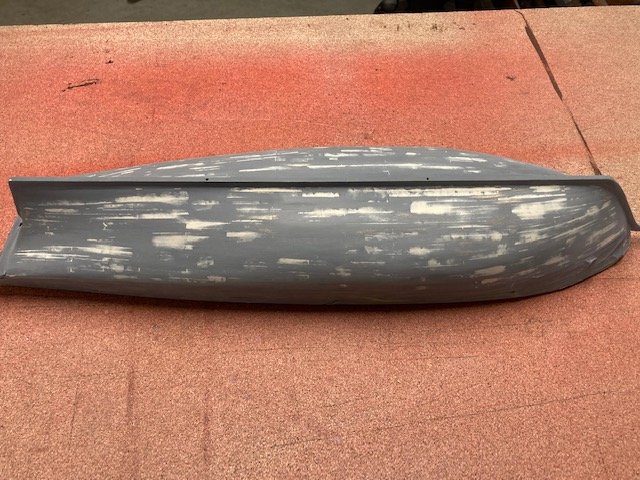
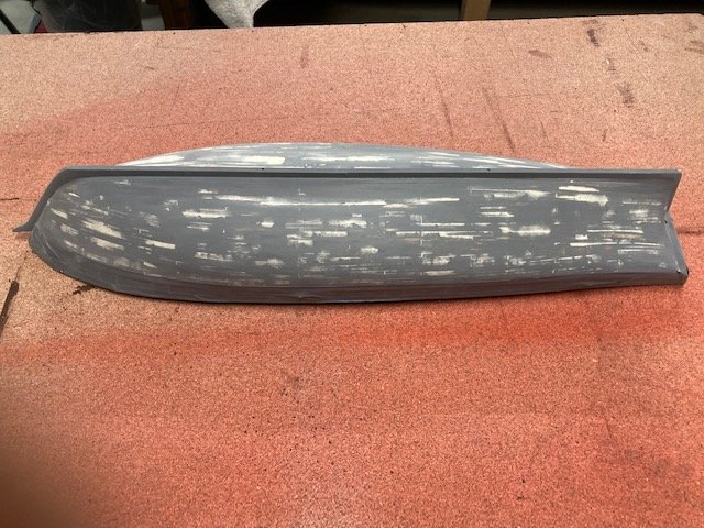
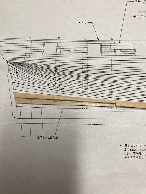
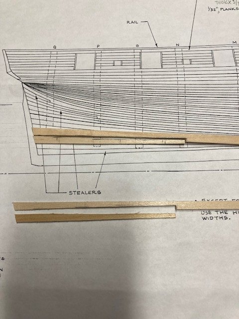
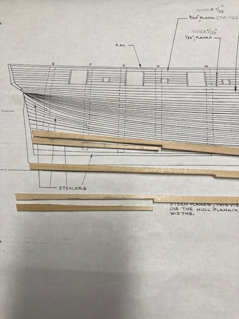
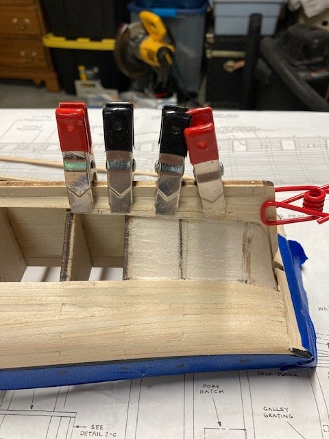
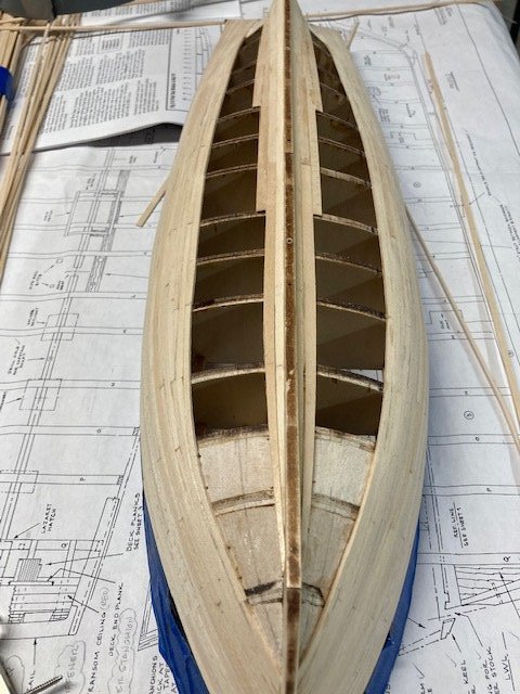
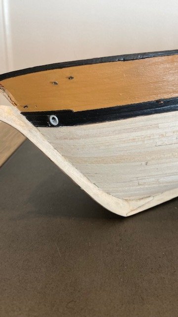
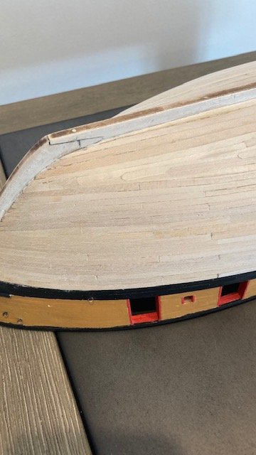
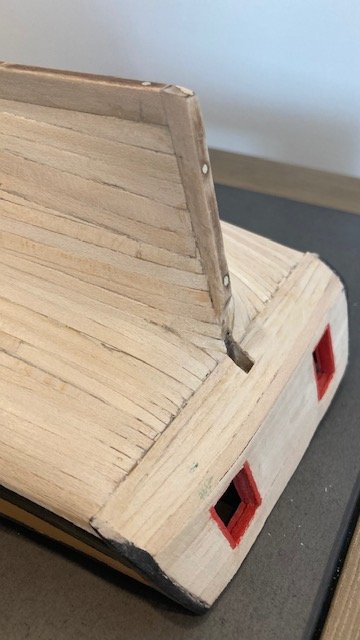
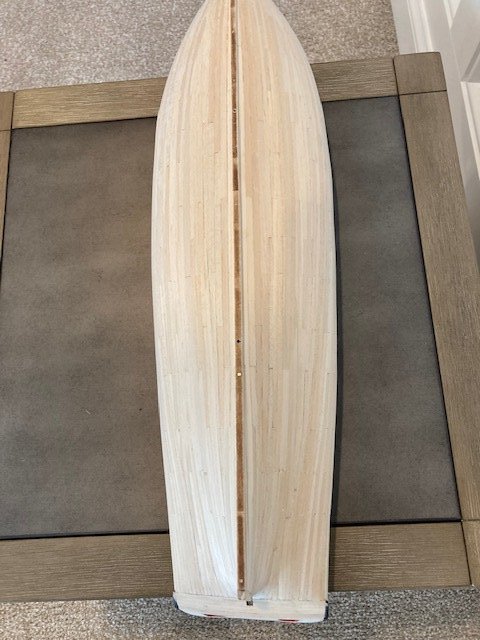
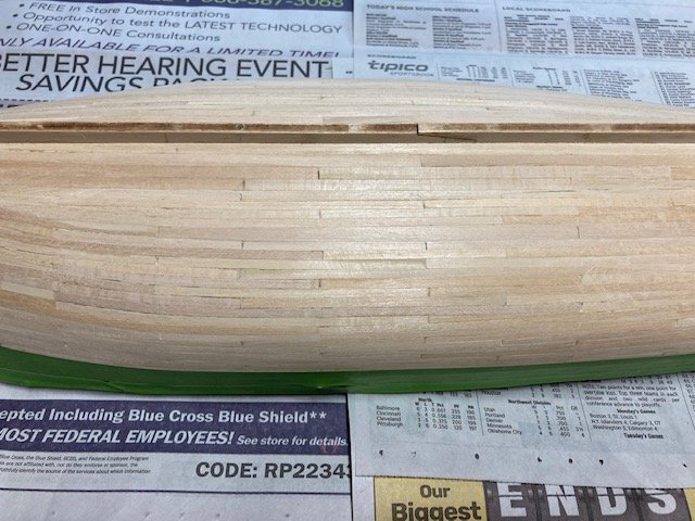
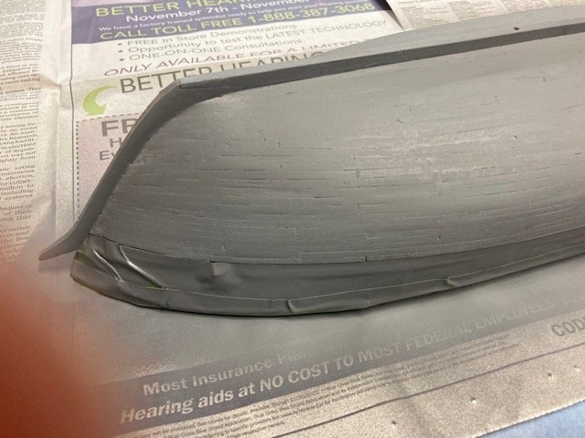
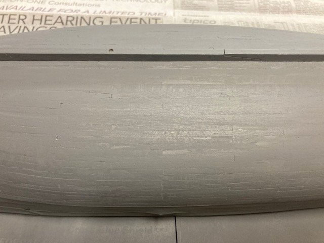
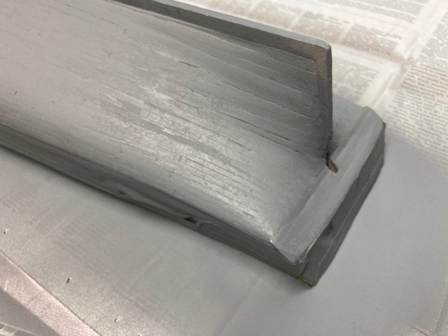
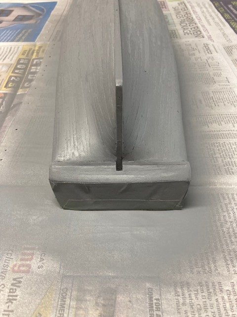
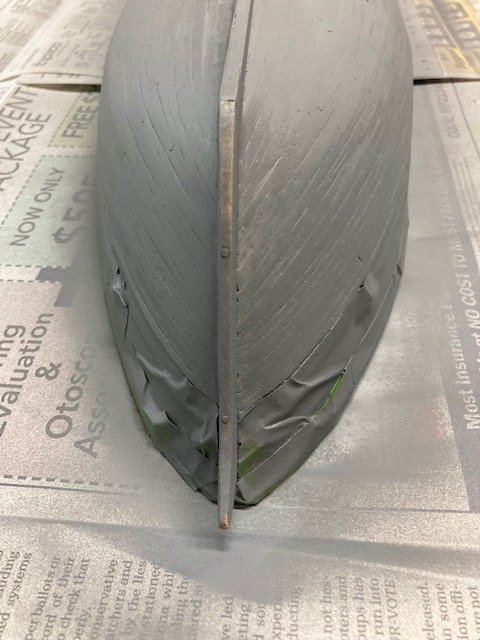
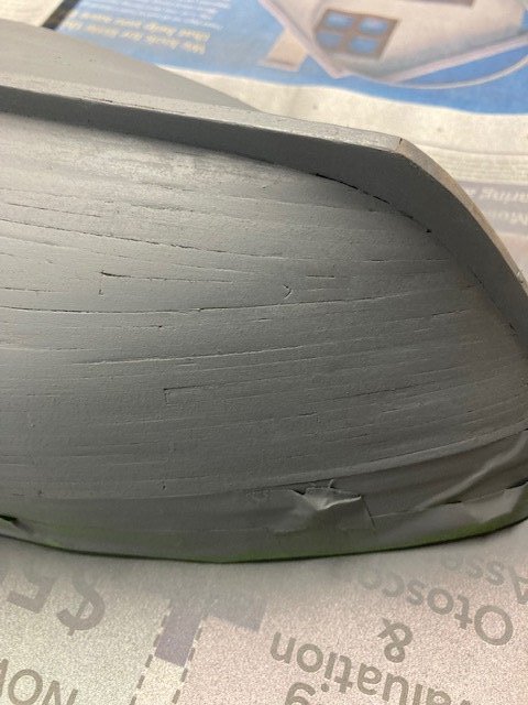
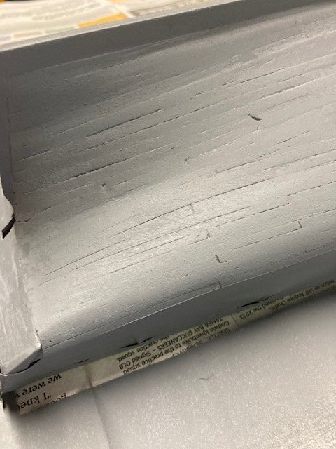
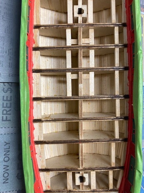
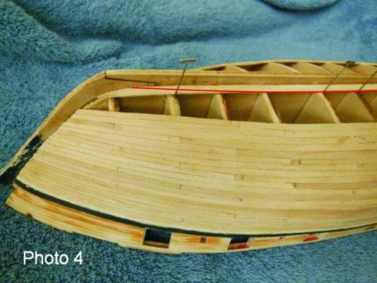
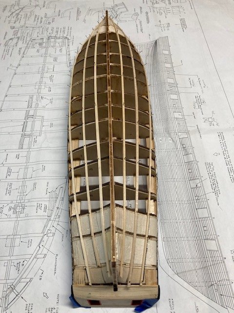
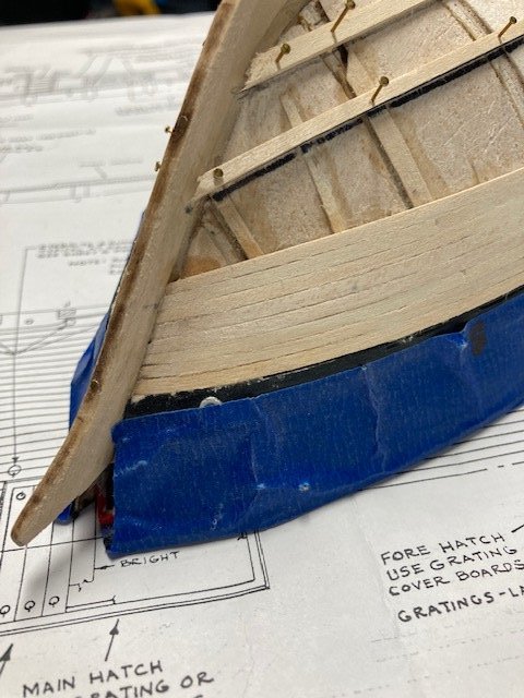
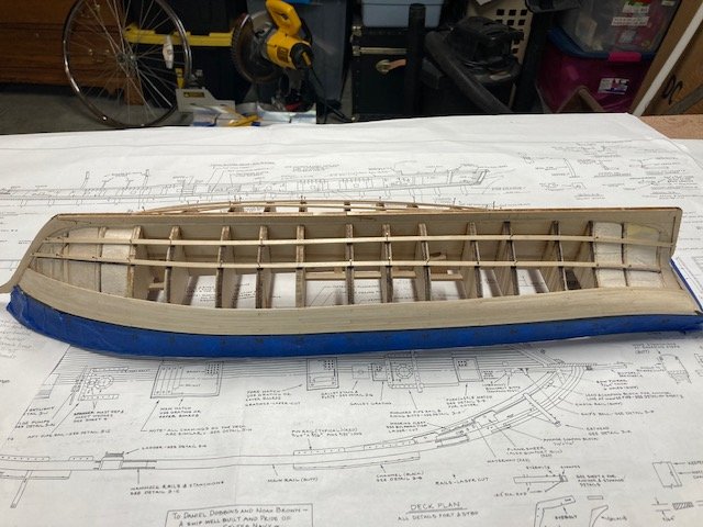
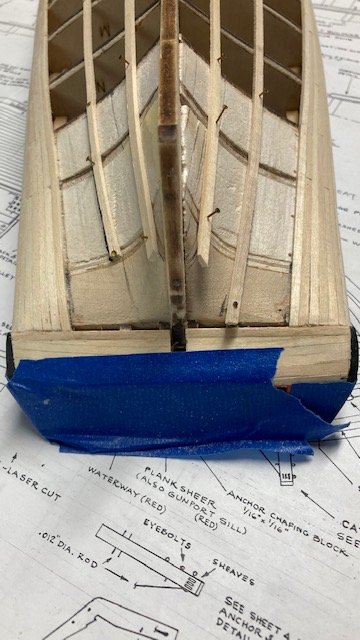
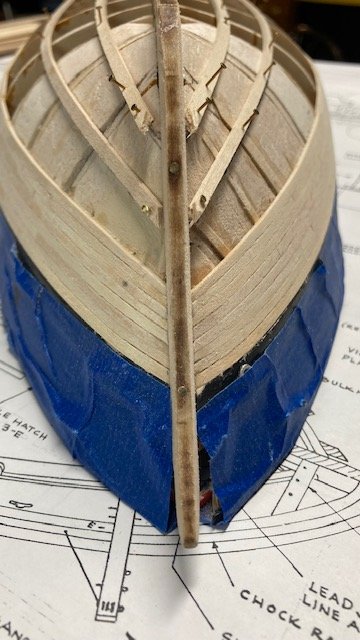
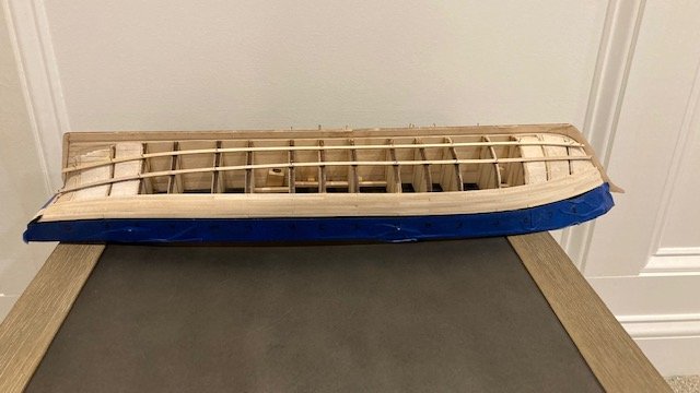
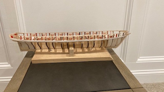
Made some significant progress on the ship. I finished Belt B planking and moved on to Belt D. Belt D has five (5) 3/64” wide (at Bulklhead H) strakes (planks) and two (2) stealers at the stern. I used the Hull Planking Profile as a guide to cut out the first stealer that abuts the keel. Next, I made the garboard strake, using the stealer as a guide. The stealer and the garboard mesh together fairly well. I used a suggestion made by Chuck in another build log and tapered the garboard toward the stem beginning at Bulklhead E (see photo courtesy of Chuck). I traced the completed stealer and garboard profiles onto another strip to create the stealer and garboard for the opposite side. I tapered the garboard to butt flush against the stealer. The second stealer abuts the garboard. Again, using the Hull Planking Profile as a guide I cut out the profile of the second stealer and the second strake. I used these profiles to create the opposite side stealer and strake. I completed Belt D and moved on to Belt C. As the space between planks got shorter, I switched from using Acco binders to push pins to hold the planks in-place while the glue dried. Finished planking the hull. The most difficult part was the closure pieces at the stern. I sanded the hull as I went along, basically while waiting for glue to dry. I did some filling with DAP Plastic Wood filler. I didn’t want to create a fiberglass like finish on the hull, so I avoided doing too much filling, so as to maintain the plank look. I did final sanding with 3/0 grit paper and then masked and spray painted the hull with gray primer (Rust-oleum flat gray). The primer shows the imperfections in the planking, so some additional filling, sanding and priming will be necessary. The following photos show the progress to date. I added a photo of the planking from inside the ship, as you don’t often see that view in build logs. Stay tuned for more updates.
-
Thanks for the compliment. Yes, a lot of painting. The instructions don't recommend when to install eyebolts and rings in the bulwark. It's a matter of preference. I installed the eyebolts before finishing the deck just to get that task out of the way.
-
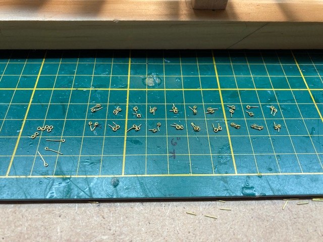
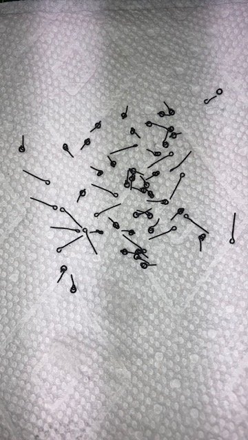
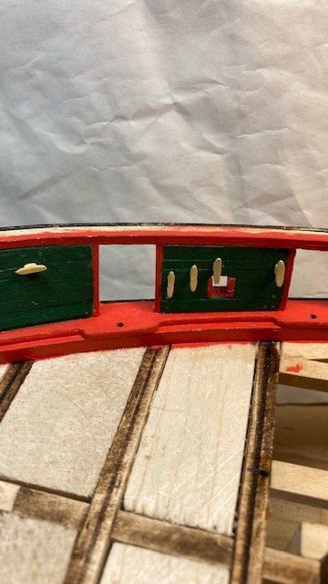
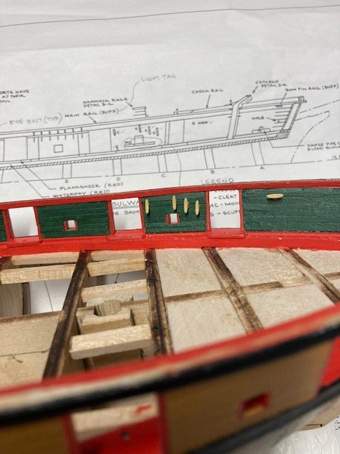
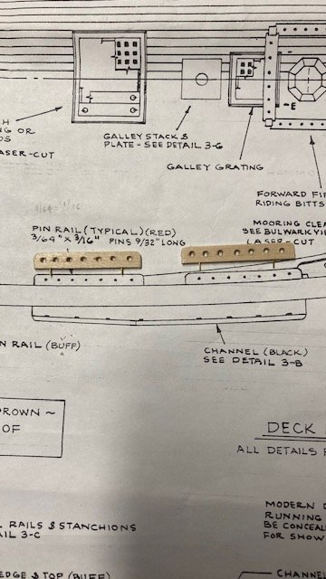
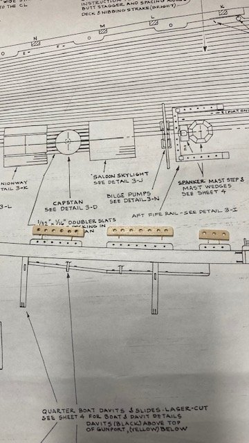
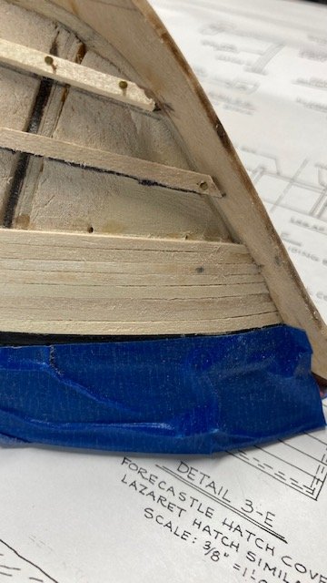
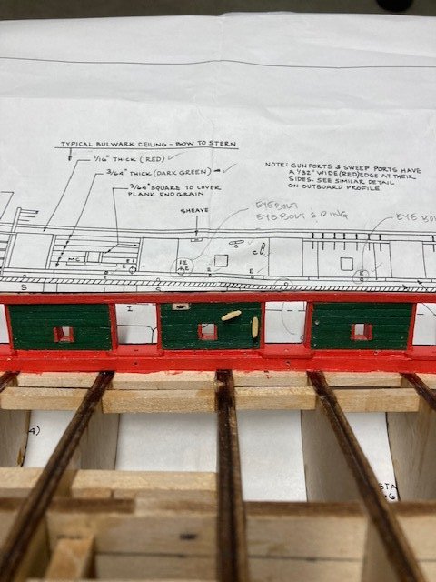
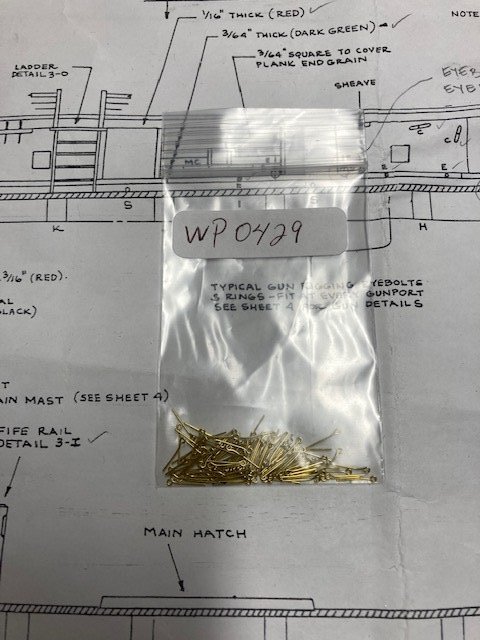
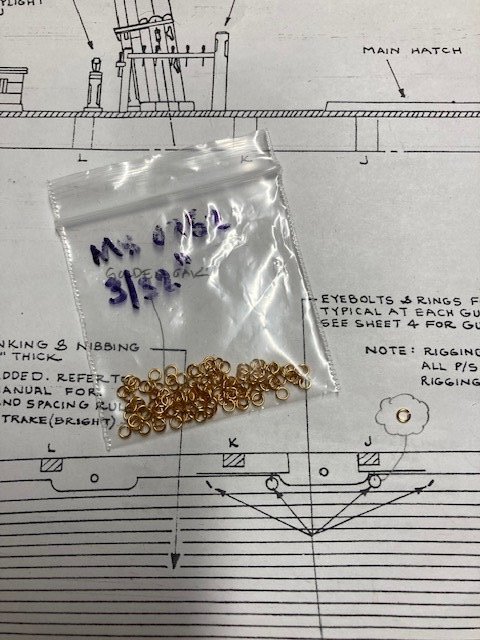
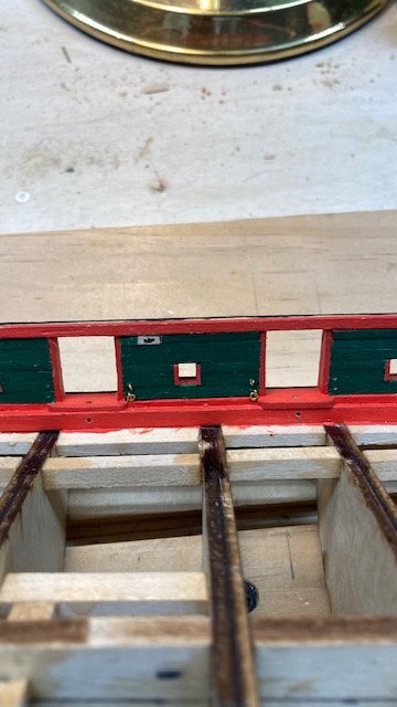
Drilled holes for the inboard cleats. There are 12 cleats port and starboard. I used cutouts from the Port Bulwark on Sheet 3 as templates to mark the locations of the drill holes. Filed the kit-supplied lead cleat prongs down to a smaller size for easier insertion in the drill holes. Painted the cleats with Model Expo Deck Light House Buff – it’s a nice contrast with the green paint. Applied a little yellow glue to each cleat and inserted it into the pre-drilled holes in the ceiling planks. While I was on Sheet 3, I decided to study the plans for the locations of other eyebolts. There are five eyebolts located on the outboard port and starboard sides of ship as noted on Outboard Profile. I drilled the holes for the eyebolts. I assume the ten (10) large eyebolts (1/16” x ½”) furnished with the kit are intended for these eyebolts – this is not clear in the manual or on the plans. However, after checking some other build logs, it was clear that the large eyebolts are to be used. No photos of these - I covered them over with blue tape before I could photograph them. Removed the laser cut mooring cleats and sanded them to remove char. I painted them black – I didn’t bother to prime them because the black paint covers well. I had planned to pin them but decided against it. I will install these later. Getting ahead of myself, while reviewing some other build logs, my attention was drawn to the number of eyebolts needed for the yards. This caused me to look at the plans further. Based on Sheet 6, if my math is correct, 104 small eyebolts are required for the yards. In addition, based on Sheet 4, 6 eyebolts are required at each of the 10 gun ports (7 if you include the train tackle) for a total of 60 eyebolts. The kit is furnished with only 120 small eyebolts. So, there is a shortage of eyebolts, not to mention the additional eyebolts that are required for the rigging. I brought this to the attention of Model Shipways, and they promptly sent me another package of 120 small eyebolts – kudos to Model Shipways. I did find at least one build log that noted the shortage of eyebolts. I made up the small eyebolts (.75mm x 6mm) with 1/8" split ring needed for the cannon rigging. I blackened these with Brass Black. Before adding anymore eyebolts I wanted to study the plans further. So, I began looking at the rigging lines for the carronades and realized that the breech line (.031”) won’t pass through the 1/8” split rings. I wish that I had paid more attention to the plans before I assembled all of the eyebolts and rings. The Deck Plan on Sheet 3 clearly shows 3/32" rings (see photo). Needless to say, I had to remake 40 eyebolts with split ring. Also, the eyebolts will have to be glued into the pre-drilled holes in the ceiling planks after the breech ropes are served to the split rings. I’m getting ahead of myself here again, but the kit supplied rigging lines do not match up with the plans. The following is summary of the kit supplied rigging lines: .008” black, .021” black, .028” black, .051” black, .008” tan, .021” tan, .028” tan Of course, you know this because you checked the parts list prior to starting your build. Here are just a few of the discrepancies in line size that I have found so far: Lines Sizes Shown on Plans: .014” tan – reef tackle, .010” tan – tiller tackle, .012” tan – spanker tackle. .016” tan cannon tackles., .031” tan – cannon breech lines .010” black – back ropes, .018” black – sheets, .021” black – sheets, .031” black – bob stays, .035” black – yard sling. I may purchase rope from Syren as others have done. I'll deal with this at the appropriate time. Moving on, I installed the spanker sheet horse. Sheet 5 says there is a ring on the transom horse, so I added a 3/32” split ring. I used 26 gauge wire for the horse. Added the eyebolt for the boom sheet fairlead (port side near gun port as noted on Sheet 5). Made up the pin rails. The kit is furnished with Walnut 5/16" (8mm) belaying pins (MS0392BW) but the parts list says the belaying pins are MS0410 which are 5/16” (8mm) brass belaying pins. The walnut pins require larger holes and the pins are closer together when the holes are drilled as per the plans. This could be problematic when the time comes to belay the lines – time will tell. I added pins to secure the pin rails. The original ship pin rails were natural finish, so I decided to paint them the same color as the main rail (MS4821 Deck Light House Buff) – it’s a nice contrast. I’m holding off on installing the pin rails until the main rail is installed. Right now, I going to start the hull planking. But, first, I applied water base polyurethane to the bulwark to protect the paint. For further protection, I covered the bulwark with blue tape. Using 1/16” x 3/32” strips, I marked the belt seams for Belt A along the bulkhead and then tacked a 1/16” x 3/32” batten strip. I measured the distance between the second strake and the batten and divided by 8 to get the approximate width the planks at the bow. I soaked the 1/16” x 3/32” strips in water overnight and put them in the jig that I made for the ceiling and bulwark planks. I started staggering the planks in a 3 butt shaft pattern, but that went somewhat array. I found it easier to work with shorter planks. In some cases, I tapered the plank edge to getting better “butt flush” fitting. I completed the starboard and port side Belt A planking. The width of the starboard and port side Belt A doesn’t quite match at the bow, and the starboard side planking isn’t quite a straight as the port side at the stern. Whence the hull planking is complete and painted this won’t be noticeable. I did some initial filling and sanding. So far, I’m satisfied with how Belt A planking turned out. Next up, Belt B.
.jpg.0b56d612c1856dcf2f8107c0c64ae1fd.jpg)

.jpg.d9ccb67ef00f876d56e23cd3e569bc1a.jpg)
-
Thanks, Thomas. There's a lot of painting required with this ship.
-
Just checking in to your build. Excellent, detailed work. Slow and steady as she goes. I’ve completed my Syren and have moved on to the Niagara.
-
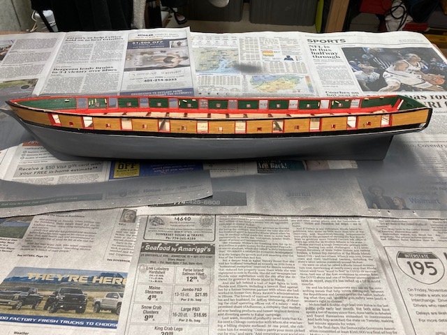
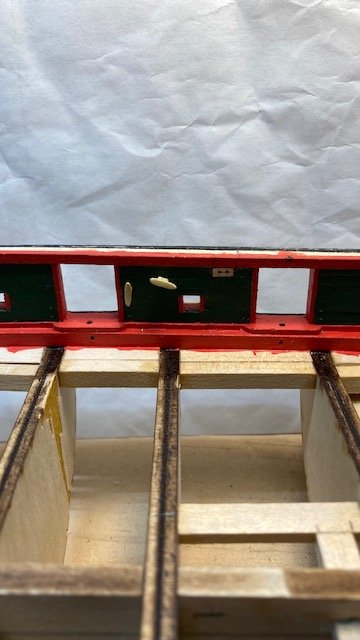
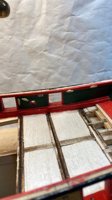
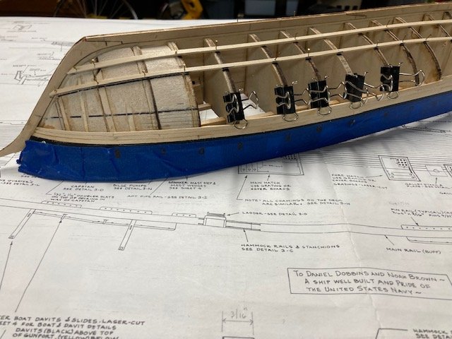
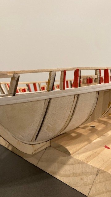
Finished the bulwarks planking. Even with much sanding and some wood filler, the planks are not even and some of the plank effect was lost in the filling and sanding process, but I’m satisfied with how it turned out. I decide to drill the holes for the eyebolts and breech tackle rings at the gun ports. There are 4 eyebolts and 2 split rings per gun port. I used a 0.6mm drill bit. I used a cut out from the Port Bulwark on Sheet 3 as a template to mark the locations of the drill holes. I made up one set of small eyebolts (0.75 mm x 6mm) and split rings (1/8”) and inserted them into the drilled holes for effect (see photo). I will need to make up another 38 small eyebolts with split rings. In addition to the gun port eyebolts, there are 9 other eyebolts located in the port and starboard planksheer/waterway. Eight (8) of these are located in the waterway, shown as a circle (o) on Port Bulwark on Sheet 3. One eyebolt is located in the planksheer, shown thus (-). Received the hawse holes from Bluejackets and installed them on the exterior of the hull. These are a nice added detail. I painted them gray to resemble lead. I also painted the inboard hawes pipe gray for added effect, although most it won’t be seen whence the anchor cable is installed. I started to look at the locations of the cleats and read that they are to be “Bright.” According to the Color Notes on Sheet 3, Bright is natural wood varnish finish. The kit is furnished with lead cleats, and I don’t know how to get a natural wood finish on lead. I’ll have to research some other build logs. Well, in my research I didn’t find much discussion on cleats. However, I did find that TomE used Model Master Wood paint for the cleats, and lb0190 used Model Expo buff color after first trying Tamiya buff. I’ve decided to use Model expo Deck Light House Buff (MS4821). Stay tuned for more progress.
-
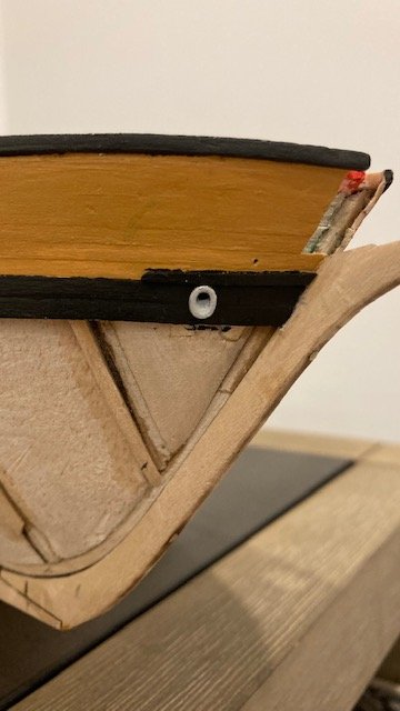
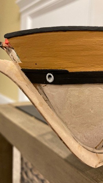
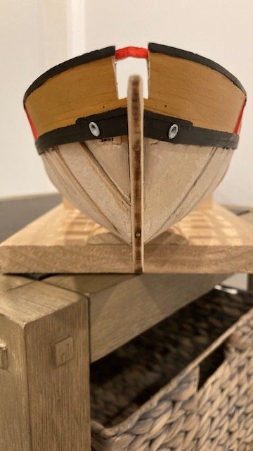
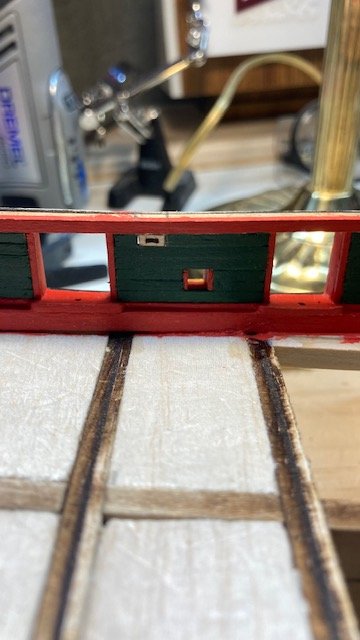
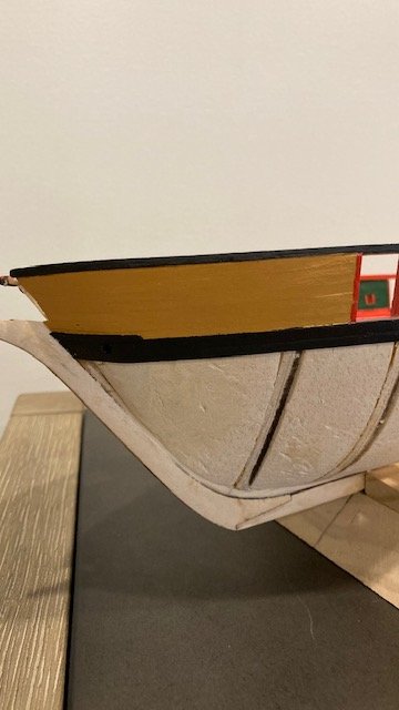
Finished the hawes pipes and the Lead & Chafing blocks. Using the Hull Planking Profile as a guide, I determined the location of the outboard hawes pipe and punched a hole just above the joint between the two strakes using an awl. I drilled the inboard and outboard holes starting with a small bit and working up to a 1/8” bit. Note: I did not use a power drill for fear of tearing the planks. Not having the bulwark planks in-place made it easy to see the alignment of the holes, so I recommend drilling the holes for the hawes pipe before adding the bulwark planks. With the hawes pipes and Lead & Chafing blocks done, I started to look into what size rope is to be used for the cable. The Anchor Stowage detail on Sheet 4 calls for .047” cable. The kit isn’t furnished with this size rope. It does come with .051” black rope. Neither of my prior builds (Syren, Fair American, Rattlesnake) used black rope for the anchor cable. I'll have to find some tan line. As another build did (I don’t recall which one) I plan to order hawse holes from Bluejackets (F0452 - 7/32" Pair) to add a little more detail. Started the port side bulwark planks at the bow. I primed and painted (ModelExpo Hull Yellow Occre MS4829) the blanks before installing them. I think the paint is a good match to the actual ship (see photo). Installed the 1/64 Doubler as shown on the Hull Planking Profile – the Doubler was painted black to match the actual ship. Note: There is a drilled hole in the bulwark plank just above the Doubler as shown on the Outboard Profile. This hole aligns with a hole on the inboard ceiling as shown on the Port Bulwark on Sheet 3. These holes are for passage of the Royal Stay backrope. A note on the Rigging Profile on Sheet 5 says the backrope is eyespliced to an eyebolt on the port side and passes through the hole on the starboard side, but Sheet 3 shows a hole on the port side as well as the starboard side - huh. The tricky part will be passing the .010 line thru the two holes - some CA on the end of the line should facilitate this. Completed the port side bulwark planking at the bow and the stern. I decided this would be a good time to drill the 1/32” holes for the scuppers. There are 5 scuppers P&S as shown and noted on Sheet 3. They are located midway of the gun ports and in the center of the second strake below the gun ports. I laid a strip of 1/16" x 3/32" deck plank down as a guide for drilling the holes in the waterway. I marked the locations of the scuppers with an awl before drilling them. It was easier to align the drills without the bulwark planks installed. If you don’t want the scupper holes to line up, then not having the bulwark planks installed doesn’t matter. Continuing with the bulwark planking, I decided to look into the location of the sheaves for the main and fore sheets. There are two sheaves port and starboard as noted and shown on the Outboard Profile on Sheet 3. On my previous builds I simply drilled holes in the bulwark to pass the rigging line through. On this build I decided to make faux sheaves from a 3/32”x 3/16” strip. It's better to do this now rather than latter. I made two drill holes on each side of the sheave and alternated drilling each side until the holes met. I then cut the strip to the dimension scaled on the outboard profile. The scary part was cutting out the ceiling plank without damaging it. This went better than anticipated. A sharp x-acto knife blade and a little filing did the trick (see photo). I have the port side stern most sheave installed (see photos). I plan to continue with the rest of the sheaves. More progress to follow.
.jpg.ddefd3bc60a21611f55a6214cc25b411.jpg)
.jpg.bd67e2ae1ccb73e67733cd12a86c3fe0.jpg)
-
Finished the port and starboard ceilings – a tedious process. I found that the Bulwarks Dark Green paint (ModelExpo MS4801) covers better if the wood is not primed. So, the planks were pre-painted without primer. Once I had a section of planks cut and fitted, I removed them, numbered them, and then painted the edges. While waiting for the paint to dry, I moved on to the next section. Whence the paint was dry, I glued the planks in place, and repeated the process. I found that some sanding was necessary to even out the planks. In some cases, where I felt there was too much space between planks, I applied a little wood putty. I little light sanding and repainting completed the section. Before moving on to the bulwarks planks, I thought this would be good time to start looking at the hawse pipe location. I marked the location of the holes on the bow ceiling and punched a small hole with an awl. I will drill the opening (1/8” ID) later. Using Detail 2-B on Sheet 2 as a guide, I made one of the Lead & Chafing Blocks for the anchor line. I used a 3/32” x 3/32” strip. I need to tweek it a little, but it looks good so far. Here are some progress photos. Stay tuned for further progress.
.jpg.864a5fa6df908bae92445c113cf67b91.jpg)
.jpg.8af0951e3f3e27bb766470a5ea87d41a.jpg)
-
Beautiful pictures. NH is definitely a scenic state - "Live Free or Die."
-
I have a little progress to report. Completed the port side and starboard side ceiling (3/64" x 3/32") at the stern. It came out fairly well, not perfect though. Most of it will be covered by the capstan bars. It was helpful to pre-paint the planks. The planks were primed and painted "Bulwarks Dark Green" (Model Expo MS4801). I found that 3 or 4 coats of green are required over white primer. Going forward, I’ll use gray primer or maybe no primer. I've come to realize that this build requires a lot of painting.
-
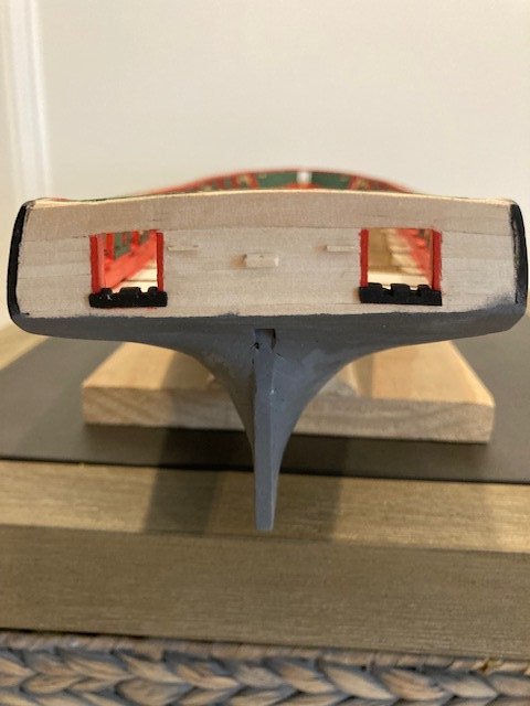
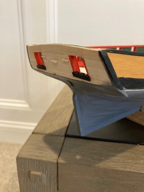
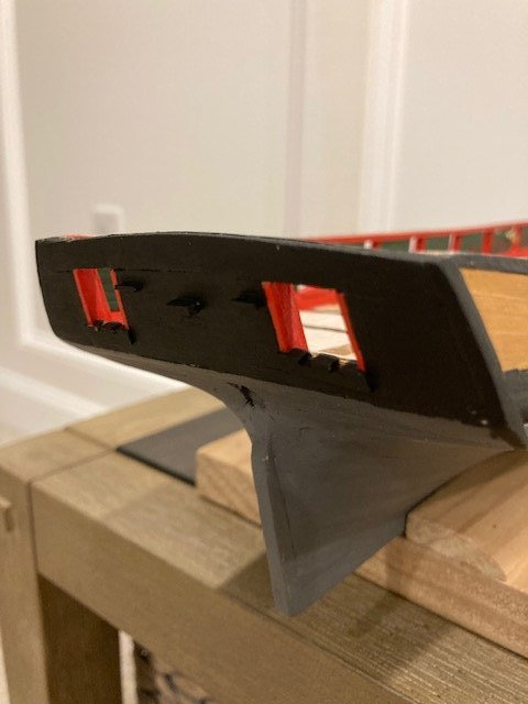
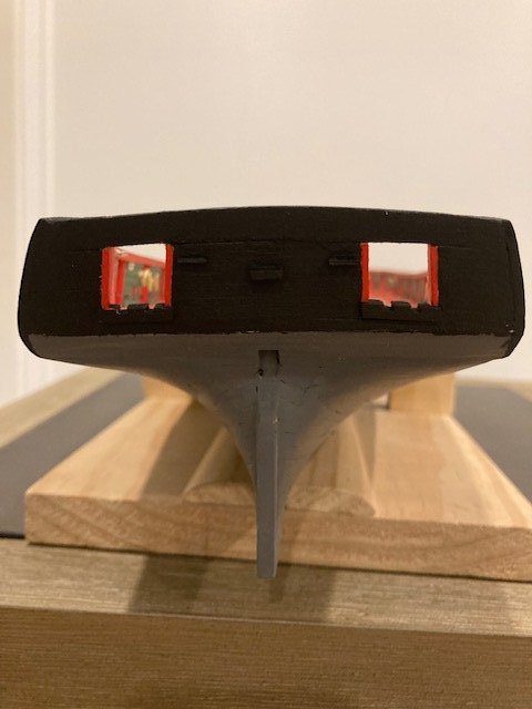
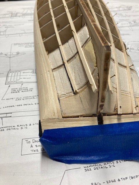
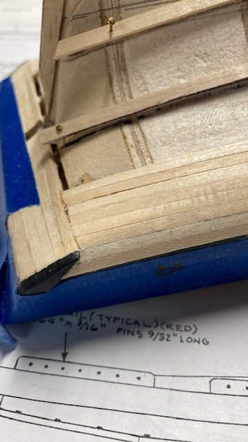
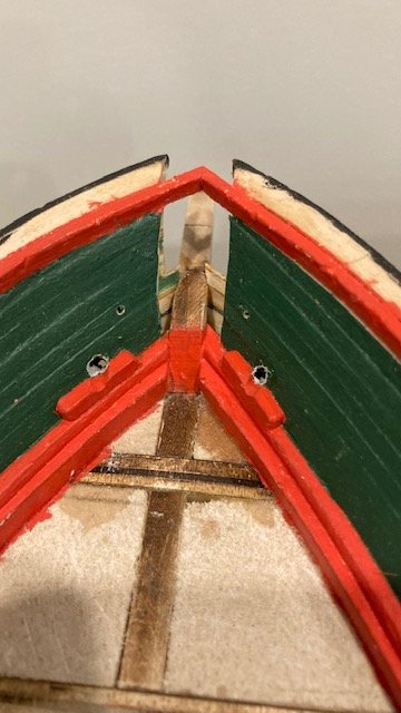
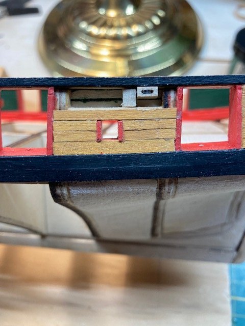
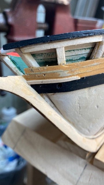
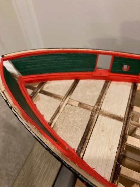
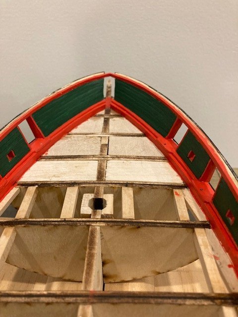
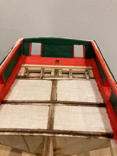
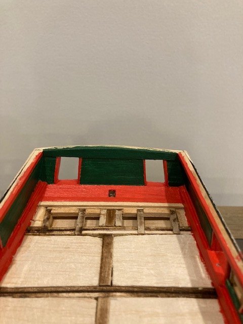
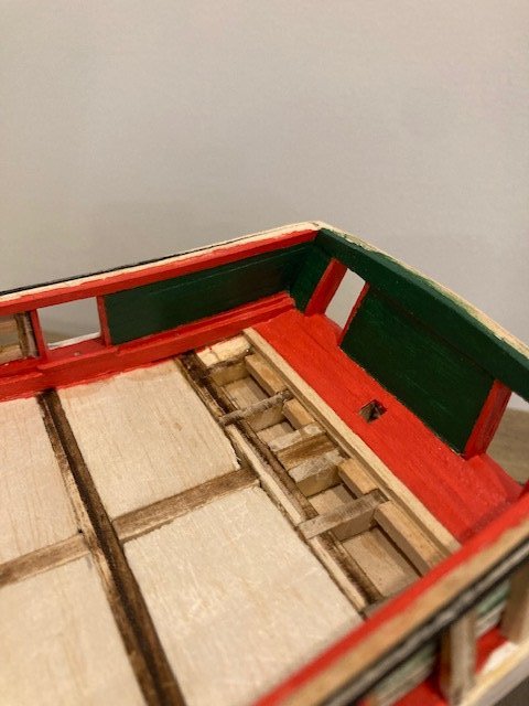
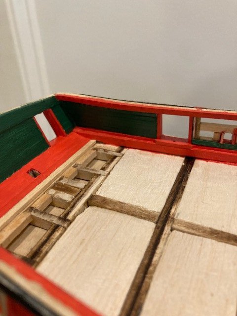
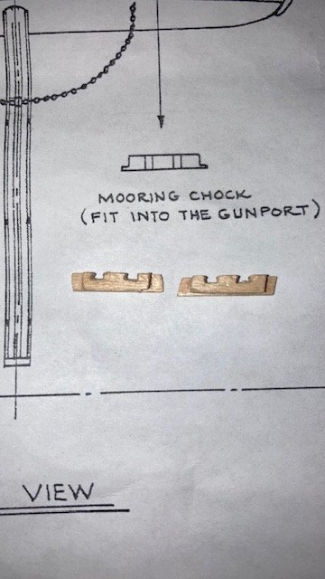
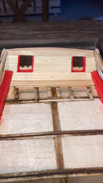
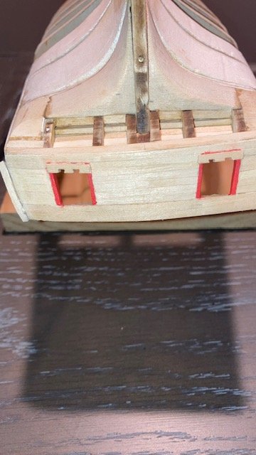
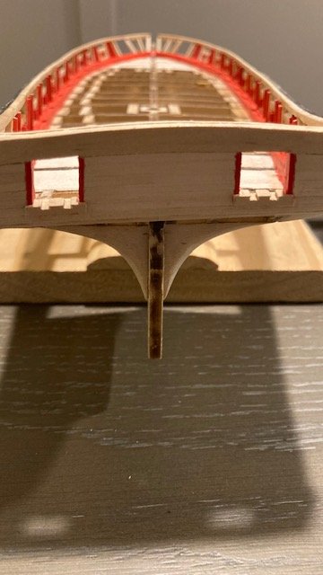
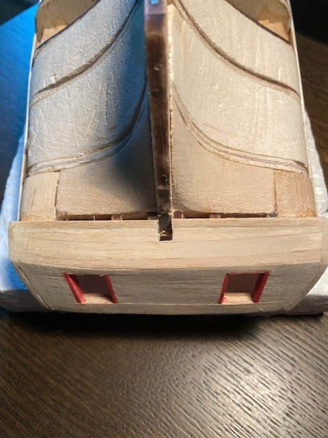
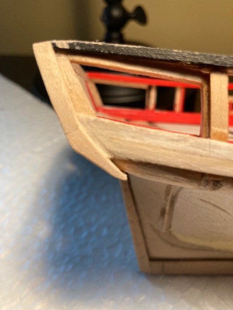
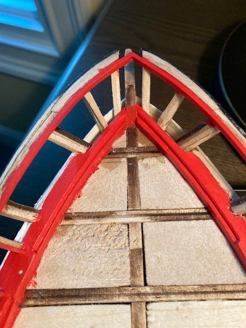
Added the first strake (the “Stringer”) below the rail. Note: the outboard Stringer is 3/64”x 3/32” and the inboard Stringer is 1/16” x 3/32”. I painted the outboard Stringers black (Model Color acrylic) and the inboard Stringer (Bulwarks Gun Red). I used CA rather then white glue. I find that CA applied with a toothpick runs into the joint and secures the Stringer – no waiting for glue to dry (see photos). Decided to plank the transom. The transom planks are 1/32”x 3/32”. At this point, I decided to check the fashion plate details. The bulkhead planks butt into the fashion plate and the transom planks butt into the transom plate. So, I cut the transom plates flush with the quarter stanchions. I trimmed the two strakes at the transom to allow for the fashion plate. The transom planks have a slight curve to match the arch board. I had to add some thin strips to the horn stanchions and the inner stanchions so that the planks would not bow in. Six planks are required from the arch board to the top of the gun port opening. The 3/32” strip that was added to the top of the top stiffener wasn’t arched, so I had to fabricate a wider plank with an arch. I used the Stern View as a template and traced the arch on a scrap piece of 1/32” thick board. I’m satisfied with the result (see photo). After reading cdrusn89 log, I decided to add some additional support at the stern between the stanchion timbers and horn timbers to provide support for the deck planks. I also added a piece to the end of the waterway on the port and starboard sides. The 1/32” x 3/32” planks for the transom ceiling were added next. I used a wider 3/64” thick plank at the top to match the transom arch. I cut out a opening drilled a pilot hole for the tiller. The tiller opening will be enlarged later when the tiller is installed (see photo). Because the bulkhead planks butt into the fashion plate, I started to add the pieces that make up the fashion plate. While fumbling with that, I decided that I should add the counter planking before installing the curved section of the fashion plate. Looking at the stern filler blocks, I figured there was no way that I could bend the 1/16” hull planks to butt against the beveled 1/16” counter plank with the filler blocks as currently configured. So, I sanded down the filler blocks. Getting back to the counter planks, I installed four 1/32” counter planks. Looking at Section 2C-C, I realized that there are two 1/32” counter planks and one beveled 1/16” plank. Also, the counter planks are arched but the beveled 1/16” counter plank has to be horizontal as shown in the Stern View. So, I trimmed the fourth plank to receive the beveled plank. This worked out well and the beveled plank aligns with the stern port. Not sure if this is correct but it looks good (see photos). Fabricated the mooring chocks from 1/8” square strip. They were a little tricky, but not problematic. They just require a lot of sanding and filing. I cut out the mooring chock from the plans and used it as a template. I marked the width of the chocks on the top and the depth on the side with a pencil. Then I sawcut a slit at an angle at each mark across the top. With an x-acto knife, I scored a line along the side depth mark and removed the cut piece from each chock. I filed each slot with fine point rounded file and cleaned it up with folded edge of a piece of sandpaper. The sides and bottom of the chocks have to be filed on an angle to match the angle of the gun ports. These will be painted black as will the transom. I had some angst about making the chocks, but they turned well (see photos). I think I'll move on to the bulwark planks next.
.jpg.92ce4bf9818fcfe45187d8b9ab24a511.jpg)
.jpg.3b1e8e116c4f9aec337a818016e795ad.jpg)


.jpg.d7462a3532edaaf9d635e1a9551a4b89.jpg)
-
I've been following your build. Excellent work. She looks fantastic. I'm in the early stages of my Niagara build. I intend to follower your build closely. One question, if I may, where did you get the rigging? It looks really authentic.
-
Since the last post, I’ve managed to make some progress on the ship while searching for a memory care assisted living facility for my 94 years old mother. I framed the gun ports and the sweep ports with 1/8” square strips. I used template blocks to get a uniform size for the gun ports and sweep ports framing. The sweep ports should be spaced 10 feet on center at 3/16” scale. For some reason, not all of mine are 10 feet o/c. I’m hoping this won’t be noticeable. Did some sanding to even out the bulkhead timbers and the gun port and sweep port framing for placement of strakes. I decided to add the strakes below the gun ports when I noticed there is a gap between the planksheer and the outer edge of bulkheads. I did read in other build logs where this was a problem. I filled the gaps with 3/32”x3/32” scrap pieces of wood strips. I sanded the scrap pieces flush with the timberheads and installed the first of two 3/64 x 1/8” strakes below the gun ports. The difficult part of installing the first strake is securing the strake at the stem (the starting point). As I moved from bow to stern, I added a dab of CA at each bulkhead to secure the strake. I find this easier than applying wood glue and clamps, and I don’t have to wait for the glue to dry. Just as a matter of note, I reviewed the plans for the bulwark and ceiling planks. The size of the planks noted on the plans is not clear. For instance, the first plank beneath the rail is noted as 3/64”, but is this the thickness or the width? The instruction manual says this plank is 3/64” thick. Well, after studying the Hull Planking Layout and the instruction manual, it’s clear to me that the dimensions on the Hull Planking Profile are the thickness and the dimensions on the Hull Planking Layout are the width of the planks. Still confused? The instruction manual calls out the thickness of the various planks. So, from what I’ve gleaned from this, I think the sizes of the strakes are as follows: 1st outboard strake below rail, the "Stringer" 3/64”x 3/32” 1st inboard strake below rail, the "Stringer" 1/16" x 3/32" Next 5 strakes 1/32”x 3/32” Next strake 1/32” x 1/8” (see Note below) 2 strakes below gun port 3/64”x 1/8” (see Note below) Belt A strakes 1/16” x 3/32” Belt B strakes 1/16”x 1/8” Belt C and D strakes 1/16”x 3/16” (These are noted on the Hull Planking Layout as 5/32”. The Parts List says to use 1/8” wide strips) Note: On the Hull Planking Profile the strake below the sweep port and the 2 strakes below the gun port appear to be wider, so I made these 1/8”. I added the 1/32” square strips for covering the edges of the bulwark planks and inboard ceiling planks. Note: Like some other build logs have noted, the 1/32" square stock is not square, so you have to be mindful which side is up when gluing in place - I'm sure that I probably missed a few. I painted the 1/32” strips with Model Shipways Bulwarks Gun Red (MS4802) prior to installing them. I measured and cut each one as they are all different to some extent. I used a 3/64”x 3/32” strip to mark the height of the strips below the 3/32” strip that was added to the tops of the bulkhead timbers. I did the outboard first followed by the inboard. I sanded them flush with the bulkhead timbers. In some places I had to apply wood putty to fill in gaps and even them out. I then painted the inside edges of the gun ports and sweeps. For the sweep ports, I decided to use a 1/32" x 3/16" strip for covering the edges of the 1/32" bulwark planks and inboard ceiling planks rather then to glue a 1/32" square strip on each side of the sweep port inboard and outboard. I cut each strip 1/4" long to account for variations in the width the sweep port framing. To accommodate the strips, I had framed the sweep ports 1/16" wider to account for a 1/32" x 3/16" strip on each side of the port. I painted a suitable length of 1/32" x 3/16" strip Bulwarks Gun Red before cutting it into individual 1/4" pieces. After installing all the strips, I evened them up by placing a piece of 1/32" wide plank against the bulwark and flush with the strip and sanding each one. To finish them off, I painted the edges of the strips and the inside of the ports. I'm not sure if this technique is any less tedious then adding individual strips on each side of the port, but it worked for me and I like the outcome. Following are photos. Now, on to the main rail and chock rail or maybe the first strake below rail (the “Stringer”). Stay tuned.
.jpg.5bf9c3d41981370b99927ee8327b4c6c.jpg)
.jpg.bddc79786d897a53dde7f736431094f2.jpg)
-
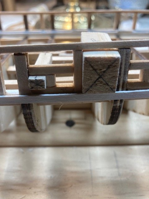
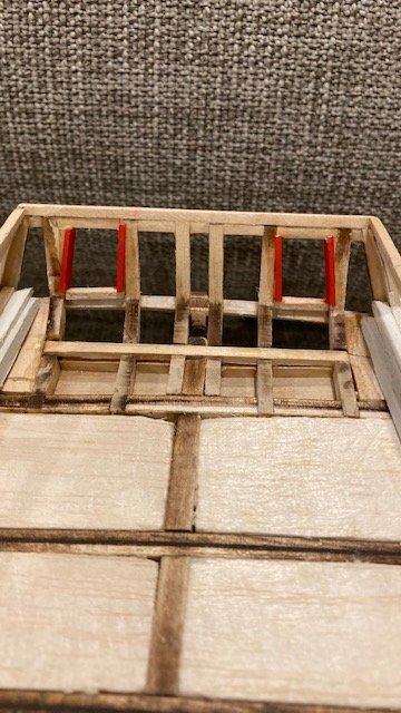
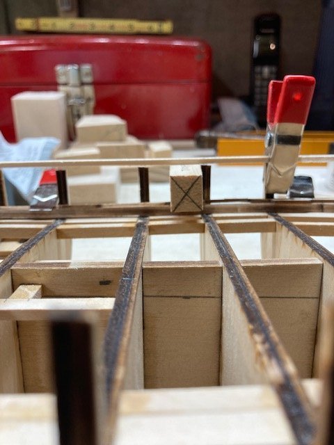
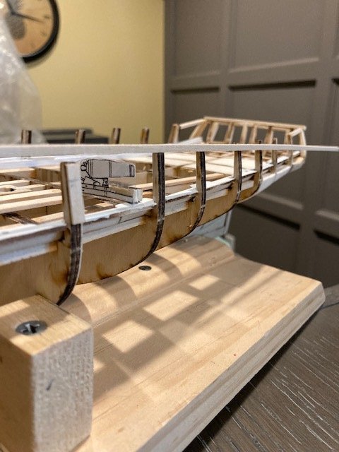
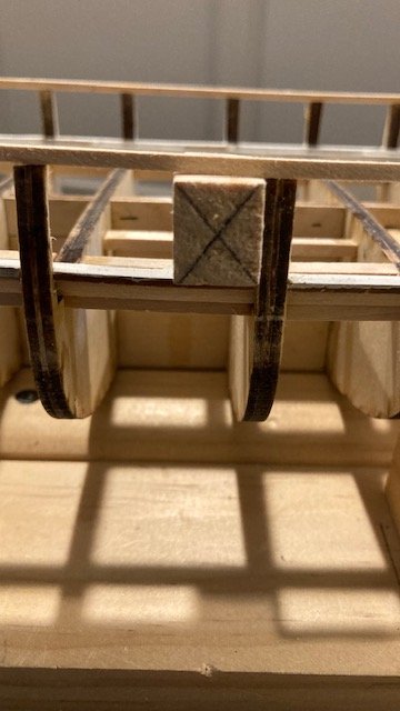
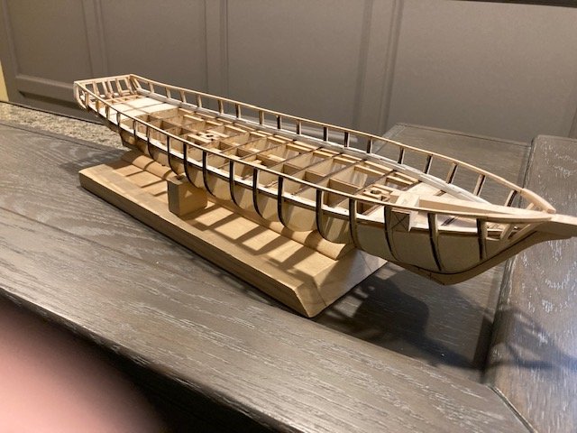
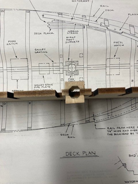
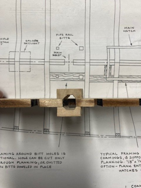
Completed installing the bulkheads. To square them up, I glued (CA) struts between each bulkhead. The struts were cut from 3/16” square wood strips. I measured the distance between bulkheads at the center keel. This basically assures that the bulkheads are square, but not perfectly square. Plus, the struts give the hull some rigidity. With that done, I did some final shaping of the filler blocks. I checked the hull’s fairness by laying a 1/8” square batten across the tops of the bulkheads. I had to add one shim on the port side. The starboard side was more problematic. Seems the center keel has a slight bend and I made the starboard side corner filler block too wide – my bad. Even after some sanding, I had to add shims at bulkheads Q, P, O, N and L. The shim at bulkhead Q is quite thick. I’m concerned down the road with the impact this might have on the rail. I added the framing for the fore rail bits, support hatch coamings, and fife rail bitts. Also, I a drilled a hole in the center keel between bulkheads M&N for the capstan. Continuing with prep work, I added scrap pieces beneath the nibbing strake for added support of the deck planks. Moving on to the task of installing the waterway and planksheer, I glued together the three laser-cut waterway pieces and shaped them to fit the timber head and the bulkheads. I beveled the edges to fit flush against the bulkheads and timber heads. I test fit and then primed them before permanently installing them. I used brass pins with the heads cut off to pin the waterway to the bulkheads. The waterway fit nicely. Next, I test fit each of the three laser-cut planksheer pieces. A lot of filing of the bulkhead timbers and the planksheer pieces was necessary to fit them. The planksheer pieces are very delicate – I broke several of them. I managed to get them to fit relatively well. I made sure that the carronade carriage pin-holes align with the gun ports. Note: the inboard side of planksheers need to be beveled from bulkhead E forward as shown in Detail 2B-B on Sheet 2. I then glued the planksheer pieces together. A la the waterways, I prime painted the planksheers off-ship. One problem with priming the planksheers before installing them is that the primer gets in the cutouts for the bulkhead timbers, so when you proceed to install the planksheers they don’t quite fit – I had to file the cutouts to make the planksheers fit properly and in the process a couple of pieces broke off – lesson learned. The plans call for bulwarks to be painted “dull bright red.” I think this is of an oxymoron. I decided to purchase Model Expo MS4802 Bulwarks Gun Carriage Red from Model Shipways. Moving on to the gun ports, there’s some discrepancy in the plans and Fig. 1-14 in the instruction manual relative to the framing of the gun ports. I have read in other build logs were the 1/8” strips above and below the gun port should not be installed. After studying the plans, the strip below the gun port is not necessary. Based on Detail 2A-A, there is no board on the planksheer. The Port Bulwark section view on Sheet 3 doesn’t show a board either. Figure 1-14 clearly shows a board on top of the planksheer, which is not correct. To best illustrate the discrepancy, I cut out the framing from the Profile on Sheet 2 and superimposed it on the Port Bulwark on Sheet 3 (see Photo). One can clearly see that the wood strip on the bottom of the gun port represents the thickness of the waterway and the planksheer and not a board on top of the plansheer as shown in Fig 1-14. Also, the dimension of the gun port height (+/-3’-3”) is consistent throughout the plans. Conclusion: no additional board is required on the bottom of the gun port. I made a block template the same size as the gun port opening dimensions. When placed on top of the planksheer, the top of the block is nearly even with the top of the bulkhead timber (see photo). So, in order to have an inboard and outboard stringer beneath the main rail and maintain the height of the gun port, a piece needs to be added on top of the timber heads from bow to stern including the transom. As other build logs have done, I plan to use a 3/32” square strip. But, before I do that, I’m concerned about the added height of the bow. Based on the View Along Centerline on Sheet 3, the main rail seats at about the top of the bowsprit. Adding a 3/32” piece would make the main rail correspondingly 3/32” higher than it should be according to plan. From what I have seen in other build logs, this is the case. It will also change the height of the cat heads. Before adding the 3/32" strip, I’m concerned about the added height of the bow. Based on the View Along Centerline on Sheet 3, the main rail seats at about the top of the bowsprit. Adding a 3/32” piece would make the main rail correspondingly 3/32” higher than it should be according to plan. From what I have seen in other build logs, this is the case. It will also change the height of the cat heads. So, I decided to make a copy of the carronade and use it as a template to see if it would clear the gun port opening. I glued the cut out to a piece of scrap wood and placed it on the deck. I added 1/16” piece of plank to account for the height of the deck (see photo). As one can see, the 3/32” strip is definitely needed. With that, I proceeded to add the 3/32” strip on top of the bulkhead timbers. Before adding the 3/32” strip, I made a template for bending the strips. I soaked the strips and then set them in the bending template to dry. I glued a strip of 3/32” across the stern timbers first and then glued the strips on top of the bulkhead timber heads. I made a 3/32” thick strip to match the top board at the knight heads. While waiting for the 3/32” strips to dry, I was studied the plans some more and discovered that stem needs to be tapered as shown on Sheet 2. This would have easier to do before assembling the keel and stem. Continuing with the 3/32” strips, I test fit the strip to see how it aligned with the tops of the bulkhead timbers. I had to file some of the timbers to get a uniform fit. I then glued each strip to the tops of the bulkhead timbers, one timber at a time. I aligned the strip with the inside edge of the timber, held it in-place, and added a drop of CA to secure it. With that done, I filed the inside edge of the timbers flush with the 3/32” stirp. I test fit the gun port template block to make sure that the gun port height was correct. I’m pleased with how the strips turned out. Next, it’s on the framing the gun and sweep ports. The following pictures show that the 3/32" strip has some high and low spots that were not obvious at the time I was adding the strip. I think I can make some adjustments when I add the main rail.
.jpg.9d55979d10509d65e93ee28984c9b59f.jpg)
.jpg.ef542faaa9a416e70807f38a1a01c230.jpg)
.jpg.f8e62be46b11b57e9ab07654a6a0139a.jpg)
.jpg.34e65f1294e178a183c48345f2e272e3.jpg)
-
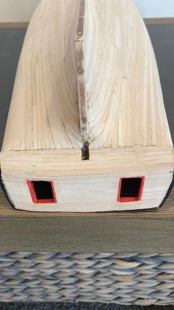
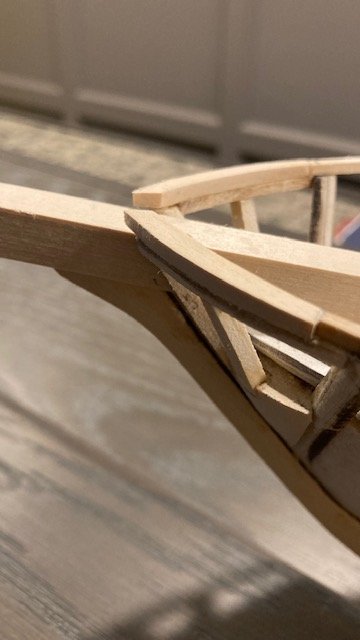
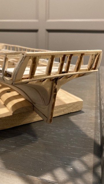
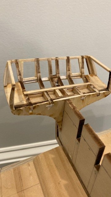
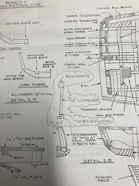
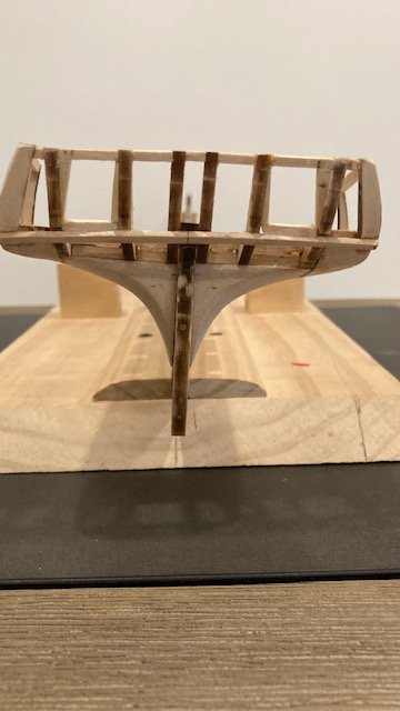
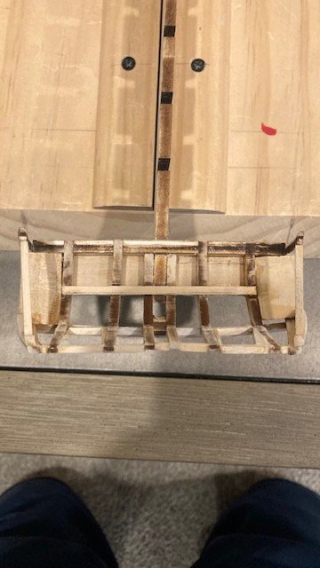
Moving on to the stern framing, I removed the bulkheads to make it easier to handle the keel and for fear of breaking off the timber heads. Next, I glued the laser-cut stern timbers in-place and then the horn timbers on each side of the center keel. Note: There is a slight difference in the size of the inner and outer timbers. To be sure, I placed them on the respective timbers in Detail 2F. I added filler blocks between the timbers. The deck beam was added before gluing the corner filler blocks. Note: The Deck Plan calls out a 5/32”x 3/32” deck beam. The kit does not come with this size stock nor is there any 5/32” wood strip. I used a scrap piece of 5/32” x 5/32” wood strip and cut it down to size. I also used 5/32”x 5/32” strip for the filler blocks. I held off on installing the beam until the stern timbers dried sufficiently. I added a little CA to the joints. I glued the corner fillers. Whence the glue was dried sufficiently, I finish-shaped the corner blocks. I decided to add the top stiffeners before adding quarter stanchions. I added the laser-cut center keel filler between the Horn Timbers. The fore side of the filler needs to be concave as illustrated on the Deck Plan. The quarter stanchions are laser-cut. They need to be tapered to 3/32” at the rail. The bottom of the stanchion needs to be shaped to receive the arch beam (see Detail 2D). A small piece of 3/32”x 3/32” is required between the quarter stanchion and the outer stern timber. Note: The quarter stanchions have an inner stanchion that is shown but not labelled in Detail 2D. It’s also shown on the Deck Plan. Detail 2D shows this in plan view, but it’s not labelled. I completed the plan view on my Sheet 2. I’m including it in this log for reference. I used yellow glue to attach the quarter stanchions. I added a little CA to secure them. I made the inner quarter stanchions from the same laser-cut stock as the quarter stanchions. The inner stanchions conform to the profile of the quarter stanchions. The outer stern timber on the starboard side broke off so I had to glue it. In so doing, the spacing between it and the inner stern timber is little wider. I'll have to make an adjustment in the gun port filler piece to correct this. Looking at Detail 2D, the rake on the 3/32” stiffener between bulkhead Q and the quarter stiffener doesn’t look quite right. So, I looked at some other build logs, which confirm that the rake of the stiffener is much steeper then it appears in Detail 2D. I went ahead and added the 3/32” square stiffeners. The next thing to do on the stern framing is the arch board. I presume the 5/64”x 5/32” is arched as depicted in the Stern View on Sheet 2. The notches for the arch board on the underside of the outer stern timbers are slightly lower than the inner stern timbers for this purpose. I cut out the Stern View and used it as a template to cut a scrap piece of 5/32” basswood board. I glued the arch board to the stern on edge. The ends were trimmed to finish it off. To finish up the stern framing, I added the gun port sills and filler pieces. There’s no discussion on this in the instruction manual. I used the Stern View on Sheet 2 as a guide. The plan doesn’t call out the size timber to use. I used 3/32” square wood strips. In hindsight, I should have used larger stock and filed/sanded it down to match the profile of the stern Timbers. I scaled the plan to determine the dimensions of the gun port opening (2.5’ wide x 3’ high at 3/16” scale). The filler pieces are cut on an angle. With the stern framing complete, I’ll move on to permanently setting up the bulkheads. Stay tuned.

-
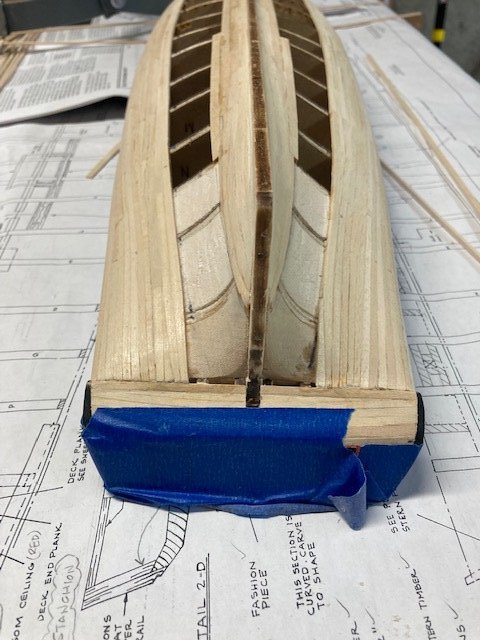
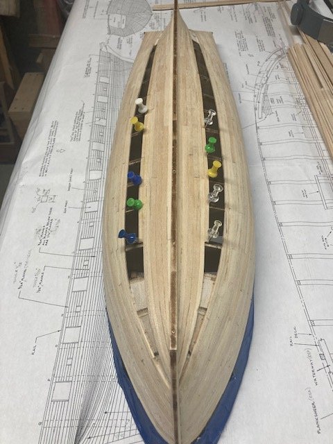
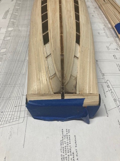
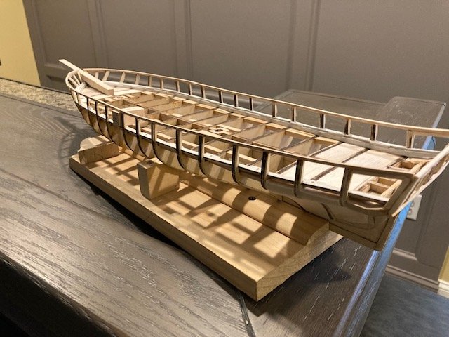
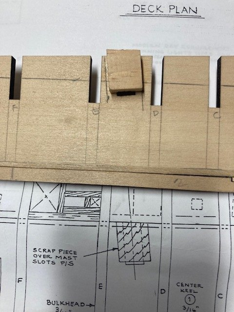
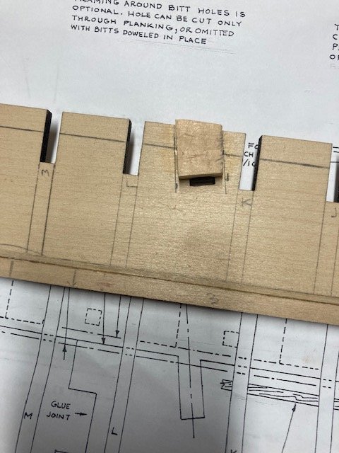
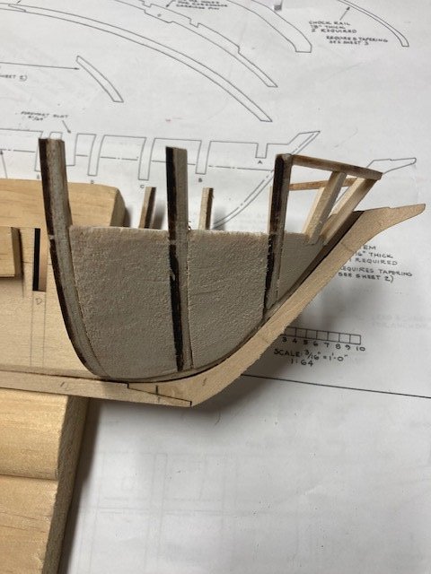
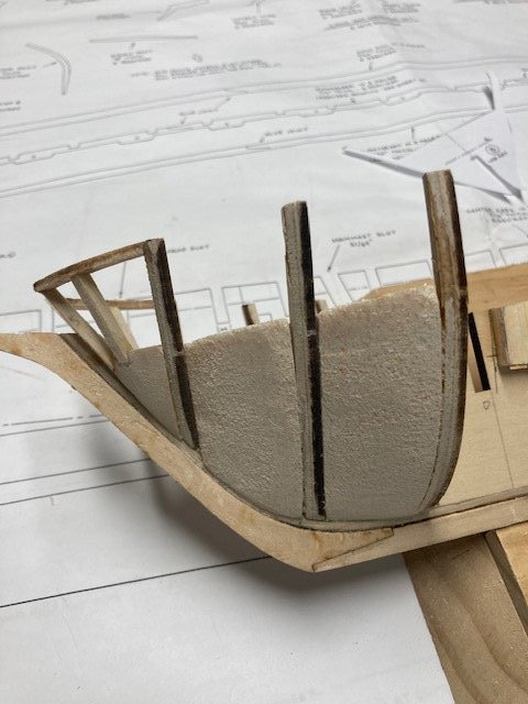
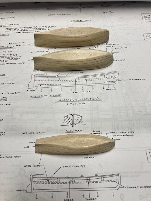
Continuing to make progress on the ship. I thought I had the stern filler blocks at the desired shape until I looked at some other build logs where the filler blocks have a shallower profile. So, I decided to shape the filler blocks some more to make the transition of the stern planking less abrupt (Not sure if it’s that obvious in the side by side photos). I moved on to the quarter boats and the stern boat. I applied wood filler to the exterior hull surfaces to even out the undulations. I sanded the hulls and repeated the process until the hull surfaces were smooth. I test fit the keel and sanded the straight bow of each boat to mate with the keel. The keels mate well except for the bow on one of the quarter boats. A little filler will be necessary on that one. I plan to cut off the rudder as suggested in the instruction manual. I shaped (rocked) the gunwales with a sanding block. The boats are finished to the point where I can start adding frames, floorboards, moldings, etc. Going back to the center keel, I added the scrap pieces over the slots before moving on to beveling the bulkheads. These need to be shaped to accommodate the octagonal shape of the lower end of the main and fore masts. I made them from scape basswood blocks. I think they would have been difficult to install with the bulkheads in-place. I beveled the various bulkheads and, like some other build logs, I added blocks between bulkheads A&B, B&C, C&D, O&P, and P&Q to provide support for the curved planks. I used balsa wood purchased from Hobby Lobby. The wood is soft and easy to shape with a Dremel, file, and sandpaper. I Whence they’re glued in-place they can be final-shaped to follow the contour of the bulkheads. I found it easier to bevel the laser cut bulkheads with a Dremel, sanding block, and file rather with a x-acto knife. So far, so good. Before gluing the bulkheads in-place, I plan to construct the stern framing and mount the corner filler blocks. Update to follow.
.jpg.531e7da26bc660bfbefa3512edd2e985.jpg)
.jpg.b683fc60de48457ebb5e7a75df9ad9d0.jpg)
.jpg.55faeb33bb8c8bfdcedfae3bc0474e40.jpg)
.jpg.a69e26c9e396861be6f29a5c19840755.jpg)
.jpg.aa552e2334e58d9acc5636e4c0c2b5a5.jpg)
.jpg.de141f479cf284da87f298ae39d1f42e.jpg)
.jpg.acb5fea509fca9730a8d62e65b71d284.jpg)
.jpg.44916a84202ca45ce77b0d44f1bec435.jpg)
.jpg.f95c55b7e52aaa12e42b9e30ff31b691.jpg)
.jpg.a51d269de9770e0ee817166c8703b9f0.jpg)
-
Fantastic model. I can only hope mine turns out as well.
-
Just stopped by to review your log. I see you haven't posted for awhile. Maybe the ship is in dry dock. Anyway, hope all is well. BTW, I recently started work on the US Brig Niagara.
-
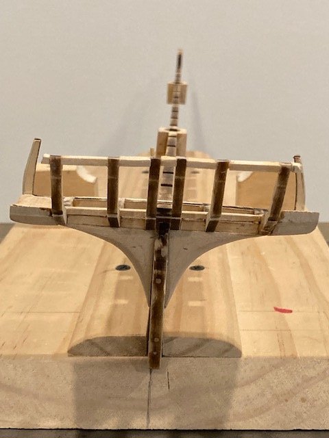
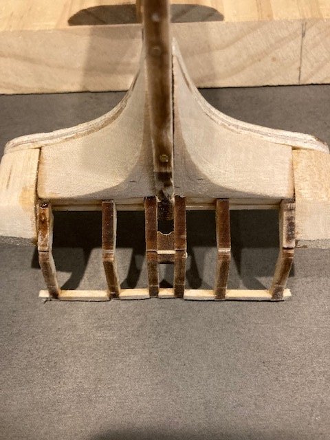
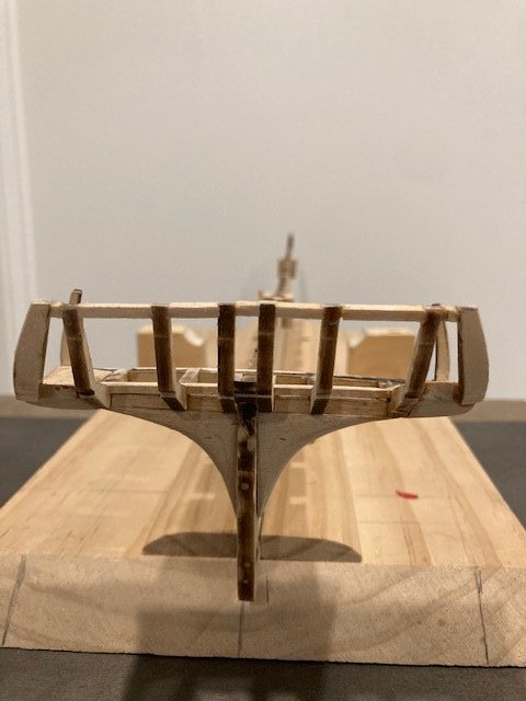
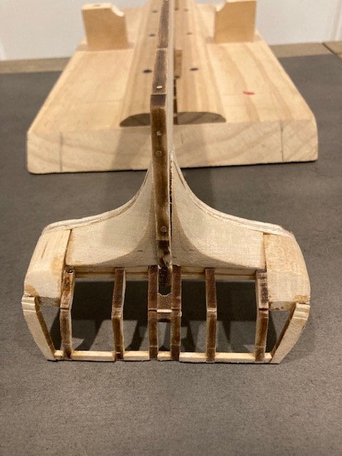
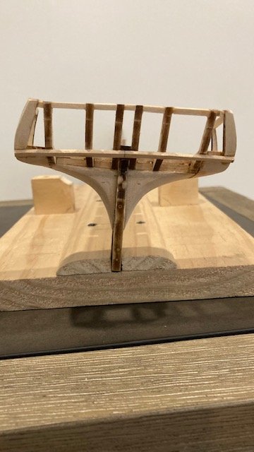
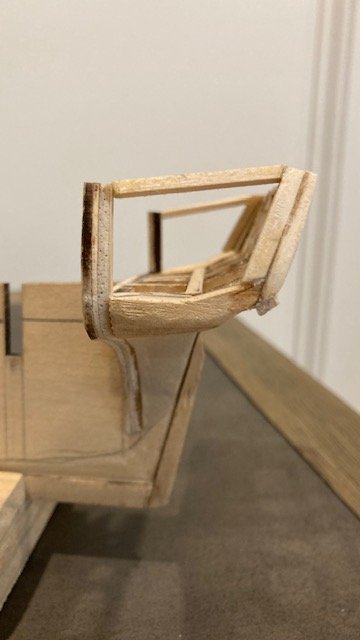
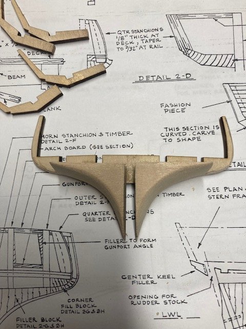
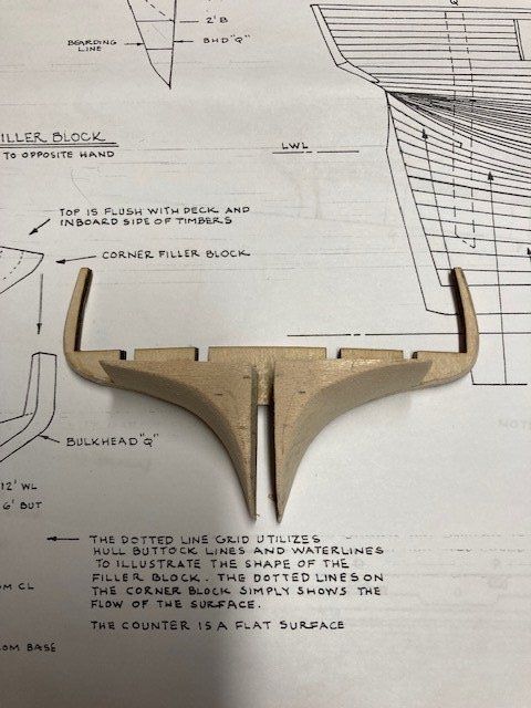
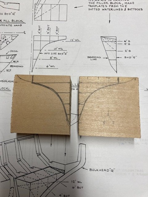
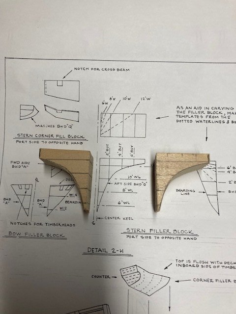
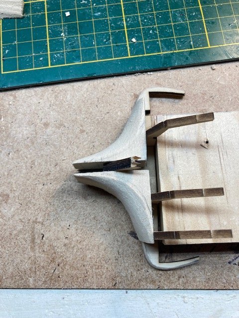
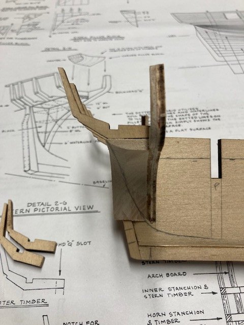
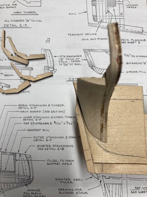
The stern filler blocks are a source of consternation and require a lot of thought. I didn’t find much discussion on how to fashion these, so I thought I would provide more detail and photos for future builders. If you can’t see three dimensionally it’s difficult to follow the pictorial (isometric) view in Detail 2G. I studied the details on sheet 2 and, using them as a reference, transferred the lines onto the ¾”x2”x2” blocks (see photo). This gave a two-dimensional image of the filler blocks from which to cut out. From there it’s matter of shaping the blocks to the desired profile. I cut the blocks out with a jewelers saw. The width of the block has to be trimmed 1/16” to match the plan view in Detail 2H. I roughly shaped the filler blocks with a Dremel and hand sanding before gluing them onto bulkhead Q. I made sure the tops of the blocks were aligned with the laser-cut stern timbers. At this point, the filler blocks need to be carved or sanded to match the profile of the bearding line. Caution: the sterns timbers are fragile. One of them snapped at the notch while I was positioning it into the notch in bulkhead Q. Glued it together with CA. I feel that have the stern filler blocks at the desired shape – time will tell when the time comes to plank the stern. Because the stern timbers are so fragile, I’m going to hold off on installing them until I set all of the bulkheads. But first, I decided to make the corner filler blocks from the ½”x1”x2” basswood blocks. These are tricky. I cut out the elevation view in Detail 2D and traced the profile onto the block. Next, I cut out the various angles with a saw and then used a Dremel, file, and hand sanding to the general shape shown in Detail 2G. I will add these and further shape them when I add the stern timbers. Right now, I satisfied with the basic shape.

.jpg.8649617eecf055770be47e69c9f6c83d.jpg)
.jpg.95d50cbd53181f41d32bdc69e8f61f93.jpg)
.jpg.2f2798ca1fc0aa3f25e098e0c7781e93.jpg)
.jpg.fa9aee386db730b73bc572c005853694.jpg)

