

abelson
-
Posts
467 -
Joined
-
Last visited
Content Type
Profiles
Forums
Gallery
Events
Everything posted by abelson
-
 Nice work on the cut out for the stern post. Molding looks good too. The moldings at the stern caught my eye as well - nice fix.
 -
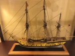
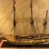
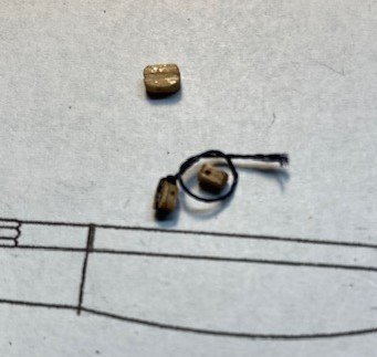
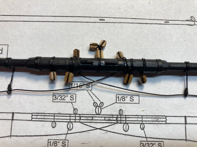
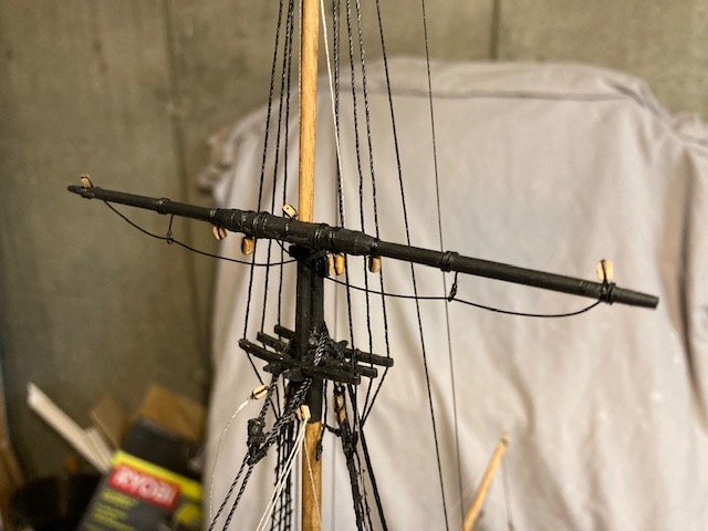
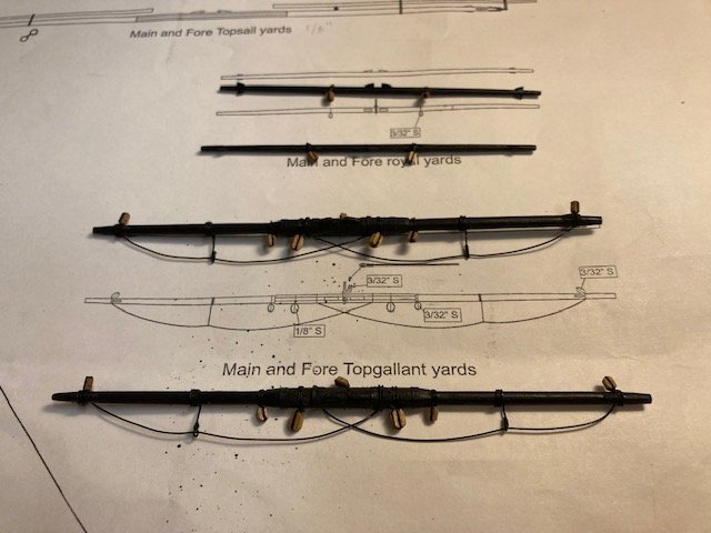
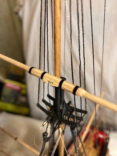
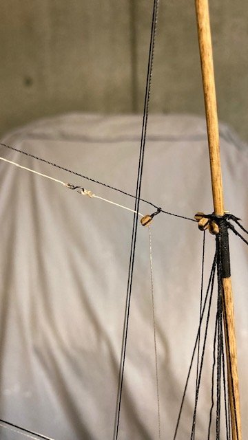
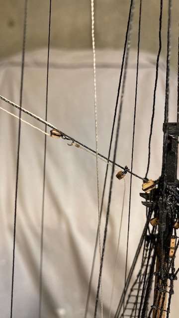
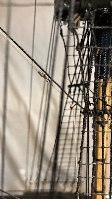
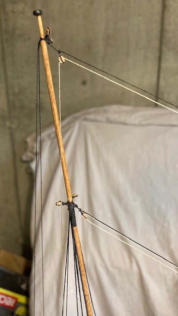
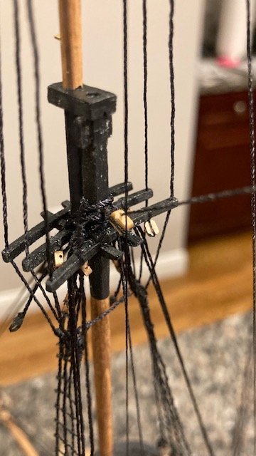
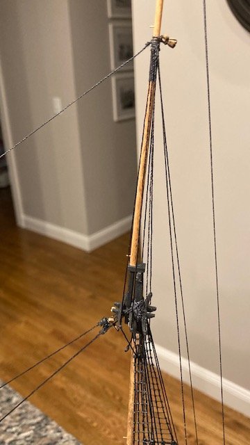
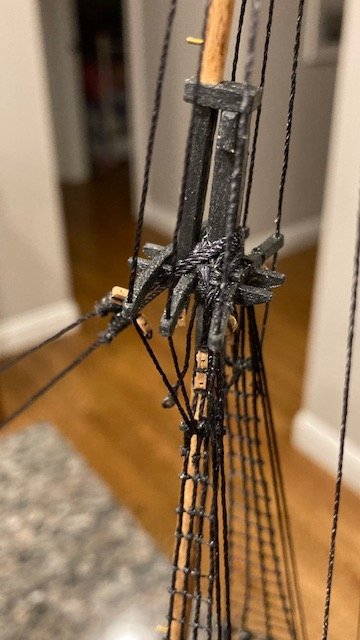
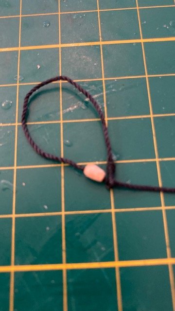
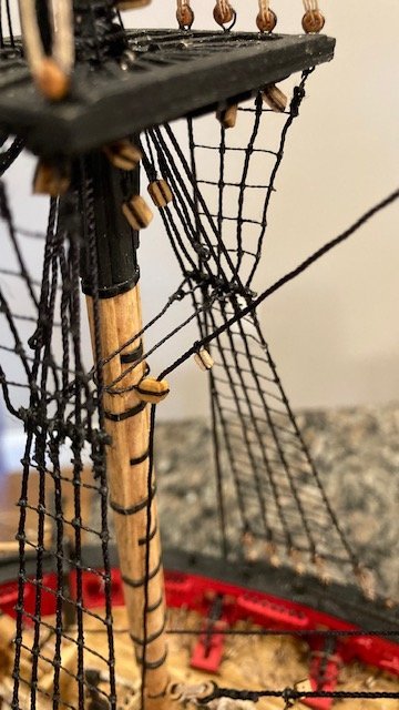
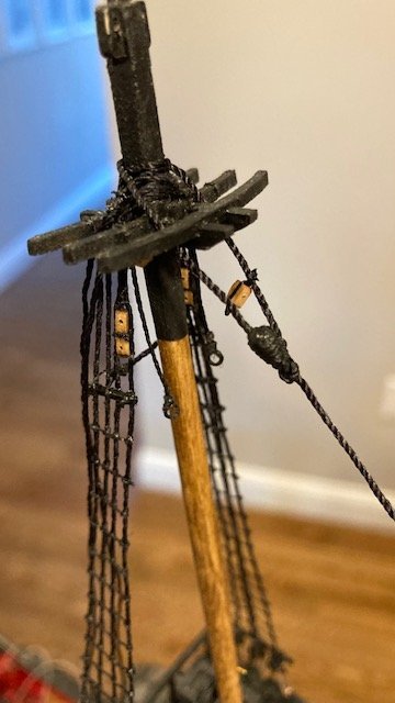
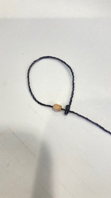
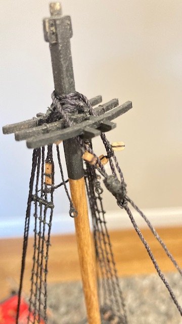
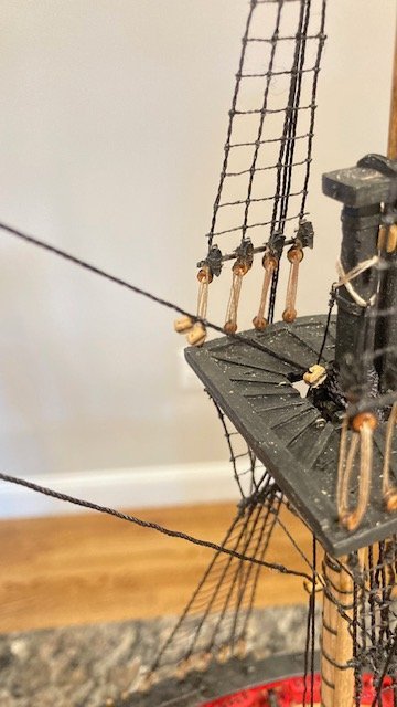
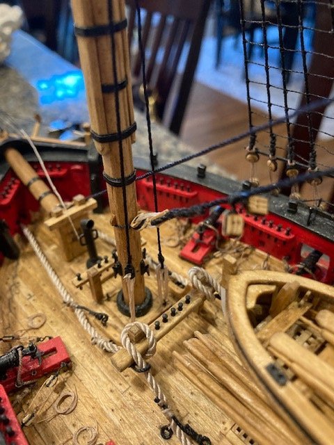
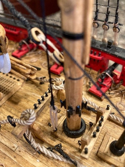
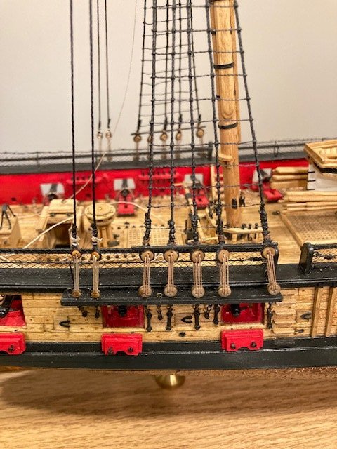
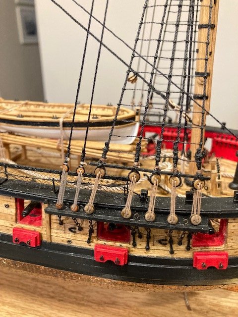
A short progress update. Finished rigging the fore and main top sail yards much the same as the topgallant yards, except for the “micky mouse ears” blocks stropped to the 1/8” single jeer block at the center/top of the yard. These are little tricky. I hadn’t found any discussion on how to rig these, so I decide to post the procedure that I used. First, the plans call for 1/16” single blocks but the instructions on Page 117 for the top sail buntlines call for 3/32” single blocks. The kit is not furnished with 1/16” single blocks, so I used 3/32” blocks. I wrapped a short length of .012 black line around the first block and tied a simple knot. I then cut off one loose end of the line, wrapped the other end around the second block and then knotted and trimmed it. Next, I cut another length of .012 black line long enough to wrap around the jeer block and the mast. I tied the line to the line between the two buntline blocks, wrapped it around the jeer block and knotted it. The completed assembly was lashed to the mast. The following photos show the sequence. The yard brace pendants were also added using .012 black line. While reviewing Desalgu’s build log it reminded me to add the “tye” to the royal and topgallant yards before permanently attaching the yards to the masts. These are shown but not labeled on Sheet 6. They are shown and labeled on Sheet 7. The royal tyes are made with .008 tan line. The topgallant tyes are .012 tan. I measured the length of the tyes on Sheet 7. I cut a 25” length of .008 line for each royal tye and a 22” length of .012 line for each topgallant tye. I allowed for making the eye on the end it the tye at the mast and setting up the tackle at the opposite end. . The fore topgallant tye is set up on the port side and the main topgallant tye is set up on the starboard side. The fore royal tye is set up on the starboard side and the main royal tye is set up on the port side (see notes on Sheet 7). Moving on to completing the lower yards. Stay tuned for update.
.jpg.5d6eb2baa5161bbc52ef67fec49e956b.jpg)
.jpg.2cf56511e4ef4af584163eca44718aee.jpg)
.jpg.96d01cc301e132d8916838676708feff.jpg)
.jpg.bf75e7a6750928cc6a1e545abb7f47ea.jpg)
- 157 replies
-
- 3
-

-
- model shipways
- syren
- (and 1 more)
-
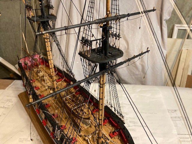
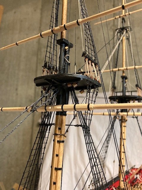
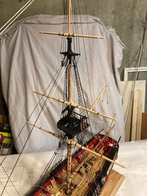
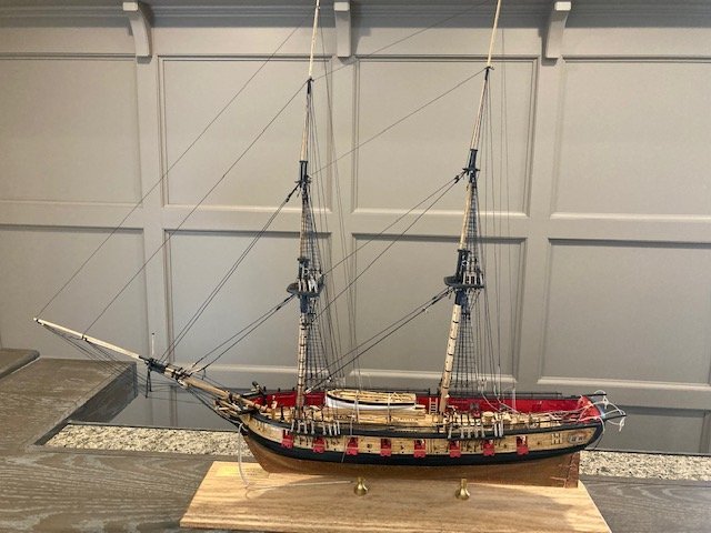
Just a short post. Finished rigging the main and fore lower yards and the topgallant and royal yards. I used 28 gauge wire for footropes. I found it easier to add the blocks before the foot ropes. Added the brace pendants too. Temporarily pinned the yards for effect. Here are some photos.
.jpg.dfcc244c0d3bfb862fdbc26f2569cbd0.jpg)
- 157 replies
-
- 3
-
-
- model shipways
- syren
- (and 1 more)
-
Thanks.
-
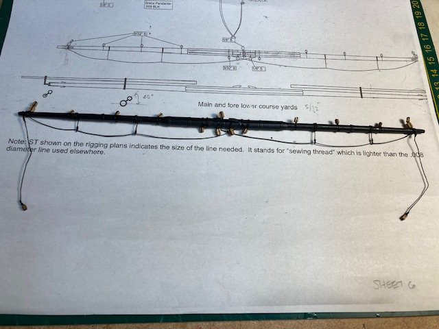
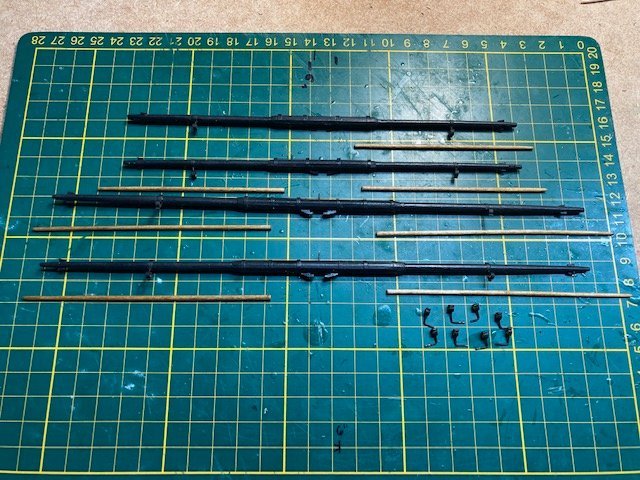
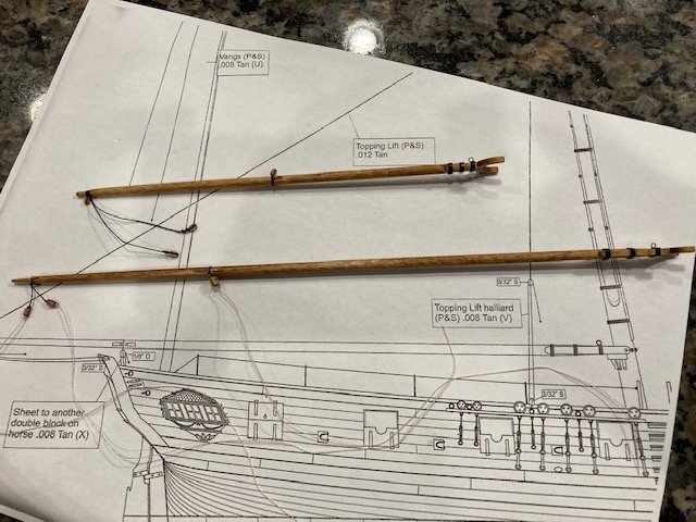
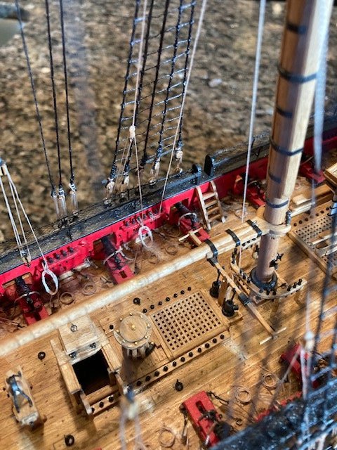
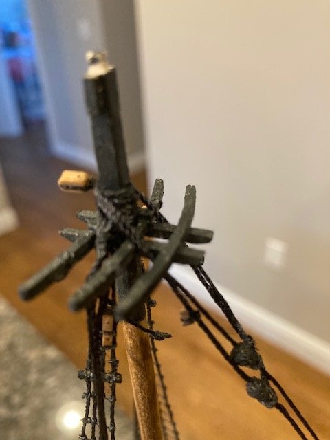
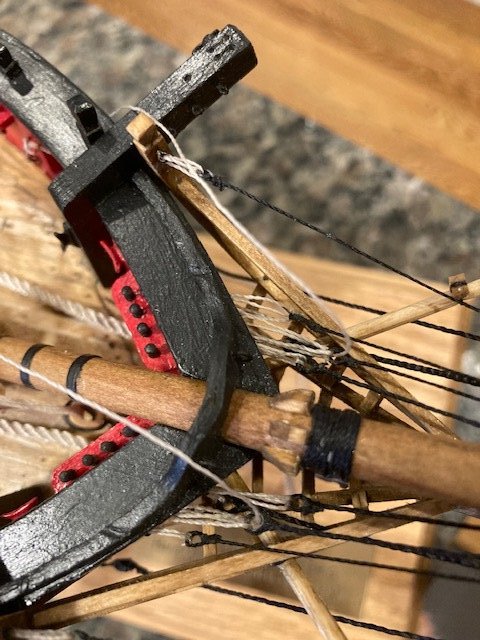
First post of the new year, and now 21 months into the build. Began constructing the lower yard arms (5/32” dowels) basically following the instructions and using the plan. To taper the dowels, I used a poor man's lathe made from two hand drills (see photo). I cut the dowels long enough to insert the ends into the drill chuck. The end the dowel that was being tapered was secured in the drill chuck. The opposite end was allowed to rotate freely in the chuck of the other drill. I used 1/16” strips to create the octagon shape. The strips were beveled. The gaps between strips (minor) were filled with wood filler and then sanded smooth. The sling cleats were made from 1/16" strips. I made a notch in the bottom of the strip and then cut two pieces to size and glued them to the yard. The yard arm cleats were made using a 1/32” strip. I applied a little CA to secure the cleats before shaping them. I copied WalrusGuy’s build log and installed simulated iron bands around the spar battens – it’s a nice supplemental detail. I also added the inner boom iron, positioned about 1/3 the distance from the end of the yard arm. I used 1/16” pinstripe tape for the bands and the inner boom iron. Applied a little CA to secure the cut ends of the tape. I drilled a hole in backside of each yard arm and pinned them, temporarily, to the masts. As much as I liked the natural look of the yards, I decided to paint them black, as most builders have done. The downside of painting them black is that the detailing is not as visible. I continued making the yards. The topsail yards and topgallant yards were constructed using a 1/8” diameter dowels. Don’t forget the simulated sheaves. The royal yards are made using a 3/32” diameter dowel. Like the lower yard arms, the topsail, top gallant, and royal yards were painted black. The stuns’l booms were next. I made them from a 5/64” diameter dowel. I didn’t have enough dowel to make all of the stuns’l booms (I was one short) so I had to order more from Model Expo - on back order. I stained the booms with Golden Oak. Note, l didn’t bother to give the inboard ends of the booms an octagonal shape. Following Chuck’s instructions, the stuns’l boom irons were easier to make than I anticipated. To simulate the hinges on the boom irons I used 22 gauge wire as per the instructions. Rather than to cut and glue tiny lengths of wire, I laid the wire on the boom iron, as if I were going to solder it, and applied CA with a toothpick to adhere the wire to the brass iron. After letting the CA set for a short time, I snipped the wire at the edge of the iron with a nail clipper and filed the ends smooth. I painted the completed boom irons black with Model Color acrylic-colors paint purchased at Hobbie Lobby. This is big step completed. Next, I drilled holes at a 45 degree angle in the pinstripe tape used for the inner boom irons. Before drilling, I pierced the tape with a sewing needle to prevent the tape from getting torn up. I inserted the inner boom irons into the drilled holes and then painted them while on the yard arm - an easy way to paint them. I test fit the boom irons on the lower yards (see photos). The yard arm footrope stirrups were made with 28 gauge wire, wrapped 3-times around the yard, and with the stirrup hanging from the backside of the yard. CA was applied to secure the stirrups. An eye was formed on the end of the stirrup and some sewing thread was added to simulate seizing above the eye. I completed the stirrups on the lower yards. More to follow. Stay tuned.
.jpg.ac920d45196bcc15bdd6abc9b6e4fc39.jpg)
.jpg.35c975818c07ef230ae590fb363558b1.jpg)
.jpg.118172a9151839e61a81f46adec46107.jpg)
.jpg.98f0d15b2e47149a98fa1e49a25338a1.jpg)
.jpg.1c1c6c98dfdf7d9b79e6f82b04c4c98d.jpg)
.jpg.f0fd7975139178f54d9cdaf9c12b4741.jpg)
.jpg.7b4dfd0aaf045a62e4e2dee8beefc0cf.jpg)
.jpg.7b25941cb3d337e6309c56de53176325.jpg)
.jpg.cf3391d6a77ad45c72877ef434536c59.jpg)
.jpg.89db9eb8d52b4c892fa50274a1cba4f3.jpg)
.jpg.1053515e1e86e939ee8f10445f584783.jpg)
.jpg.f5e0e90f4ad52cc5bca6c6673c1517a8.jpg)
.jpg.1a76751bd75f61b949581908c574d66e.jpg)
.jpg.63767971c4d9745bd4cfec04642d0e25.jpg)
- 157 replies
-
- 5
-
-
- model shipways
- syren
- (and 1 more)
-
Nice work on the scratch build capstan.
-
Nice color choice.
-
Excellent working rudder.
-
As usual, excellent work.
-
Excellent work on the coppering. One of the better ones I've seen. I'm enjoying your progress.
-
Oh, you're too kind. I'm glad my posts are worthwhile. Yeah, the closeups do tend to show imperfections. You just need a little more sanding. FYI, I had to grind my pedestals to fit the keel.
-
Excellent work on planking. Keep it up.
-
Rudder looks great. I like the beefy look of the ladder. I made my midship boarding ladders thicker too. Used 3/32”x 1/8” basswood strip. And, yes it is difficult to get symmetry. FYI, I found that the carronade tackles interfere with the ladders or vice versa. This is not obvious from the plans. Keep up the good work.
-
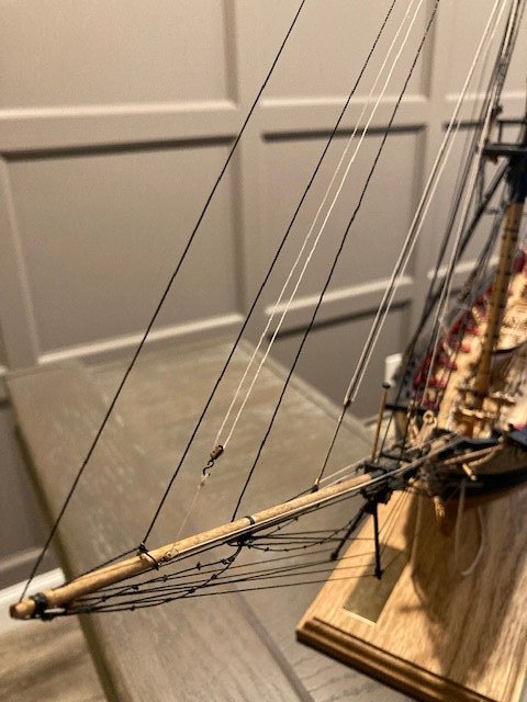
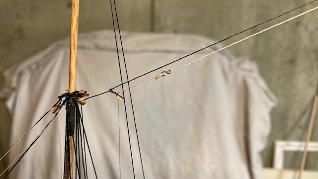
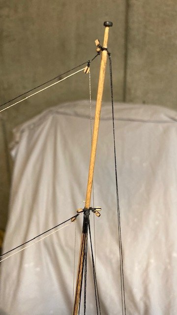
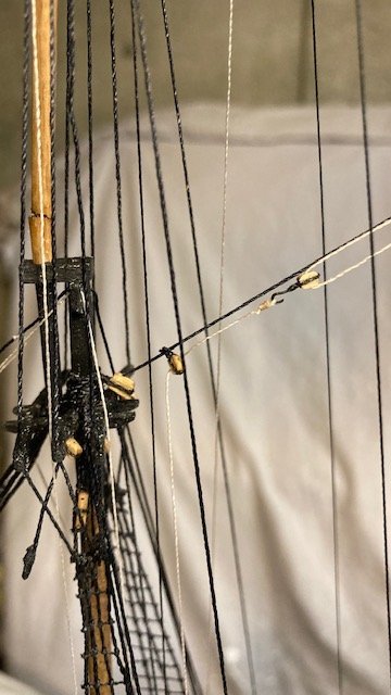
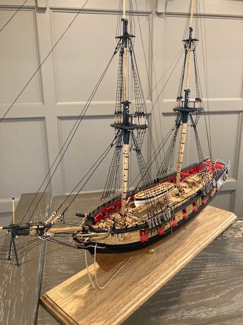
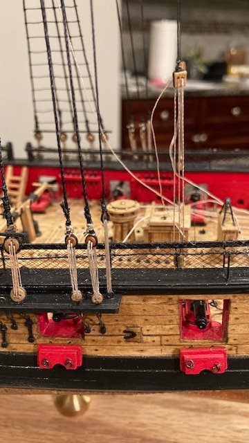
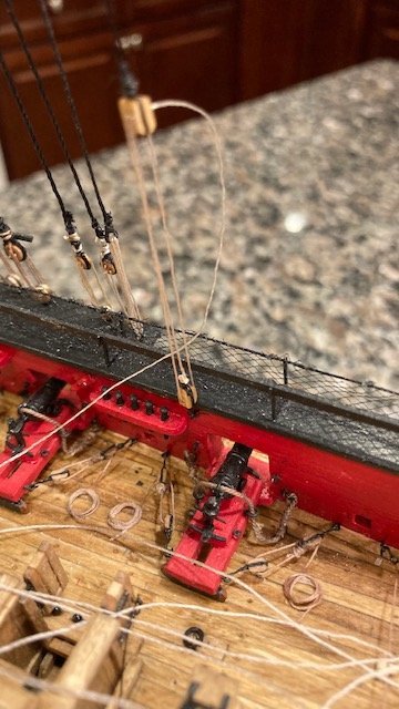
Started on the main topmast staysail downhaul. I had previously seized the 3/32” single block to the main topmast stay. I created an eye on the end of the .012 tan downhaul line. So far so good, but, I could not run the line through the block. This is where it all fell apart, literally. In trying to run the line through the block, I snagged one the lines, and pulled down the fore top mast (the Fid broke). Another oh s__t moment. I was ready to put the ship in dry dock. Upon assessment, I was able to push the fore top mast up and secure it with CA. A disaster averted. But, Murphy’s Law crept up. Somehow, the fore topgallant mast/pole snapped above the cap. It snapped at the point where I had inserted a pin to hold the royal yard. I’m not sure if this was a ramification of the of fore top mast mishap. In hindsight, it was a bad idea to insert the pin – it weakened the mast. Luckily, I was able to set the mast back into position and secure it with CA. It lists a little but, considering the consequences, I can live with that. I decided to take a little reprieve to regroup. Well, after a short reprieve, I was able to rig the main topmast staysail downhaul (.012 tan) and main topmast staysail halliard (.008 tan). The downhaul was run through the Lubber’s hole and down to the port side rail abaft the main mast and belayed to pin “N.” I was able to snag the pins and belay the lines in the traditional under/over manner. Moving on, I seized 3/32” single blocks, two on the main top gallant stay and two on the main royal stay per the plan on Sheet 6 and set up the main topgallant staysail downhaul (.008 tan) and the main topgallant staysail halliard (.008 tan). These lines are belayed to shroud cleats above the main and fore tops. The cleats are not depicted on the plans, but their locations are noted on the Belaying Plan. It’s a little confusing, so study the Belaying Plan well before proceeding. The main topgallant staysail downhaul (.008 tan) is belayed to the aft-most shroud cleat (O) on the fore top port side. The main topgallant staysail hilliard (.008 tan) is belayed to the 2nd shroud cleat (P) on the main top port side. I assumed the 2nd shroud is the 2nd fore-most shroud. I found it very difficult to belay the lines, so I simply wrapped the lines around the cleats, applied CA, and snipped the lines. They’ll be covered later with rope coils. Completed the remaining staysail rigging (.008 tan) per the instructions. The Belaying Plan clarifies where the various lines are belayed. I did have one minor do-over, I had earlier seized the 3/32” single block for the flying jib sail downhaul on the starboard side of the traveler ring rather the port side as explained in the instructions. The lesson here is, don’t get too far ahead of yourself. Again, I had a very difficult time belaying the downhaul lines to the pin rails at the bow. I was unable to do it in the conventional way. It looks really amateurish. Hopefully, the rope coils will hide this. If anyone has a good way to do this, I’m all ears. Oh, I did have another do-over. The fore royal stay became slack while rigging the flying jib halliard, so I had to re-do the lanyard at the bow. The staysail rigging was clearly not my shining moment, but I’m satisfied with how it turned out. Now, on to constructing the yards. This will be the last post this year, so happy holidays to all! Photos follow.
- 157 replies
-
- 4
-
-
- model shipways
- syren
- (and 1 more)
-
Excellent innovation.
-
Excellent, detailed roof! You have a lot of patience - a ship builders virtue.
-
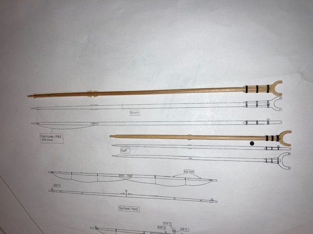
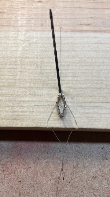
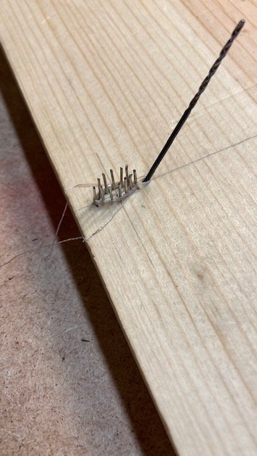
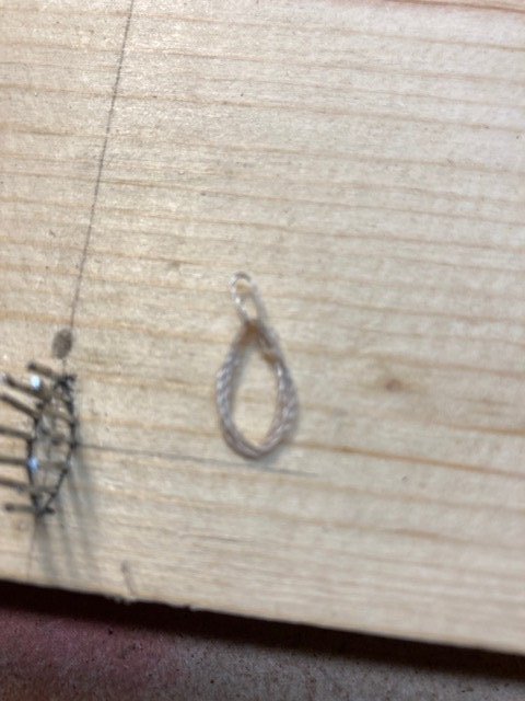
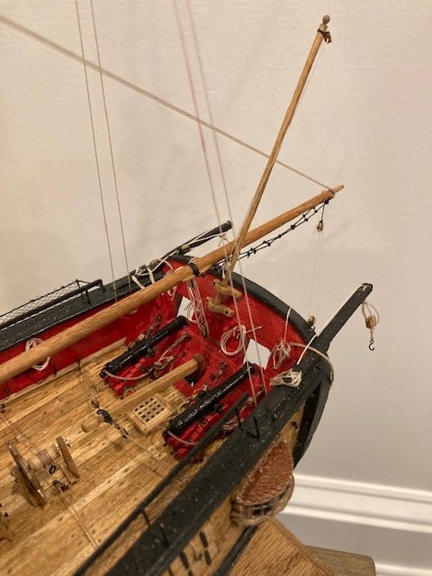
Completed the boom and gaff. Following the instructions, this was a fairly easy, enjoyable task. Tapering is the most time consuming part. For this, I used a battery powered drill. I cut the dowels long enough to allow for inserting them into the drill chuck. I decided to leave the boom and gaff finish natural. I applied one coat of Minwax Golden Oak. I painted over the pinstriped simulated iron bands with black paint. FYI, there’s a discrepancy on Sheet 6 - the gaff cleats should be on the side of the gaff and not on the top and underside as depicted in the plan view. The elevation view shows the cleat correctly as does the picture on Page 108 of the instructions. I fell victim to the discrepancy. It was one of those oh s__t moments. I have noticed that others have fallen victim to this discrepancy too. Also, there is another discrepancy on Sheet 6 - the elevation view shows the gaff vangs seized to the pendent block. This is not correct. The vangs are seized to the eyebolt on the bulwarks. Added the 3/32” single blocks on the gaff as shown on Sheet 6. Rigged the vang pendants (.012 blk) ahead of time. Seized a I/8” double block to the eye on the gaff jaws. Blackened the beads and strung them (6 beads per parrel) on the parrel lines and seized the lines to the boom and gaff jaws.Insert Attached the gaff to the mast below the catharpins. In doing so, I realized that another bead was necessary, so I added it. The loose end of the parrel line was reeved through the jaws, tied off and secured with CA. I set up the gaff throat halliard with a generous length of .008 tan line that I had previously seized to the 1/8” block under the main top. The loose end of the halliard is belayed to the port side pin rail. The peak halliard was next. It was rigged as per the instructions and belayed to the fife rail. With that done, I added the vangs (.008 tan). I decided to attach the boom to the main mast before completing the gaff rigging. After seizing the parrel to the jaw, I realized that I forgot to add the foot ropes – I wanted to do them with the boom off ship. BTW, I discovered another discrepancy between the plans and the instructions: The instructions say to use .012 black line for the foot ropes but plan Sheet 6 calls out .008 black line. I decided to use .012 line to match the jib boom. I cut two, 6” lengths of .012 line --and added the foot rope knots (11 per rope) on each length. I left loose ends on the knots so that they could be adjusted and trimmed. I Seized one foot rope to the boom, adjusted each knot so that they are ¼” apart, applied CA to each knot, and cut off the loose ends. For the second rope, I tied the knots and spaced and trimmed them before seizing the rope to the boom. Completed the boom topping lifts, boom sheet, and boom sheets, and finished them off with rope coils. In the instructions, at the end of the boom topping lift paragraph, it says, “Note the “leg” of .008 rigging that runs from the topping lift to the boom. It is shown on the rigging plans. This should be rigged as well.” It is not shown on the plans. SalD’s build log picked up on this too. He notes that the line is shown on page 122 in Chapter 20 – it’s in the photo on Page 125 in my instructions. Thank you, Sal. I tried adding the “leg” but had difficulty. So, I decided to leave well enough alone and to not add the leg. I notice some other build logs have done likewise or otherwise overlooked this. I had previously made flag staff chocks, so I decided to add a flag staff which was made from 1/8” dowel. I also added the flag staff halyard (0.008 tan). The flag staff halyard runs through a 3/32 single block at the end of the staff. The free ends are tied off to a cleat on the side of the flag staff. The end of flag staff has a ball made from the head of a craft pin and painted gold. I added some rope coils at the transom. One of the things that I find difficult with rigging is belaying the lines to the rails. What helps is CA glue. After the initial wrap around the belaying pin, I apply a little CA to the line. This keeps the line taut and allows for wrapping the line around the pin at the top of the rail. I apply a little CA with each pass, if necessary. For the rope coils, I made a jig using Tom Lauria’s Rigging Tips: Making Scale Hanks on YouTube. I laid out an ellipse measuring ½” x 3/16”. I drilled 12 holes along the perimeter of the ellipse and inserted a common pin in each hole. I then nipped off the pins at a height of about ¼”. I used a 1/16 drill bit for the loop. The first coil didn’t come out too well. The second was a keeper. Each subsequent coil was a challenge – some were keepers, some were throwaways. I’ll need to make many more. Moved on to finishing Chapter 18 by adding the Flying jib stay (.018 blk), Jib Stay (.018 blk), Inhaul for the jib stay traveler (.008 tan), and Inhaul for the flying jib stay traveler (.008 tan). These were done as per the instructions. The only problem I had was belaying the lines. I found it very difficult to belay the lines in the traditional under/over manner in such tight guarters. By luck, I was able to snag one pin and belay the line in the traditional manner. For the others, I simply wrapped the line around the head of the pin and glued it. I'm hoping the rope coils will hide this. Next, it's back to Chapter 19 and the staysail rigging. Stay tuned.
.jpg.3bf6ad22f01a8486d914d1628b387c1e.jpg)
.jpg.f242818d4b3e00e2bee9fab96e23142a.jpg)
- 157 replies
-
- 4
-
-
- model shipways
- syren
- (and 1 more)
-
Looks like nice symmetry.
-
Slow and steady wins the race. Looking good.
-
Good idea on leaving the lanyards loose until the stay and preventer are tight. Looking good. BTY, I think you need to add another eyebolt abaft of the fore mast.
-
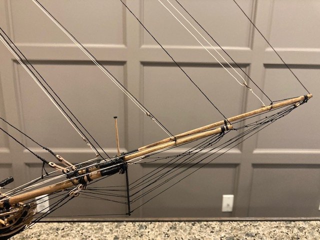
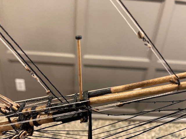
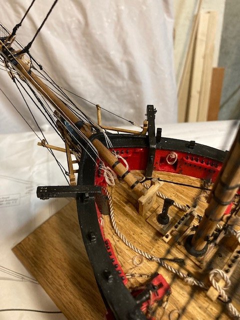
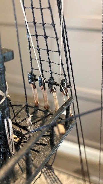
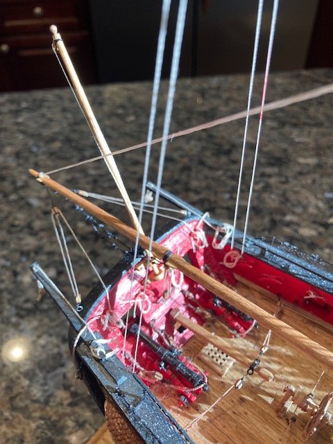
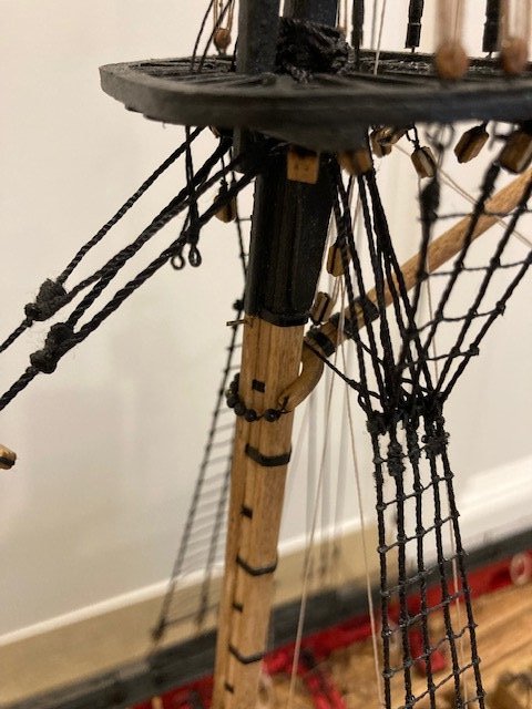
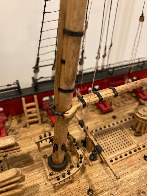
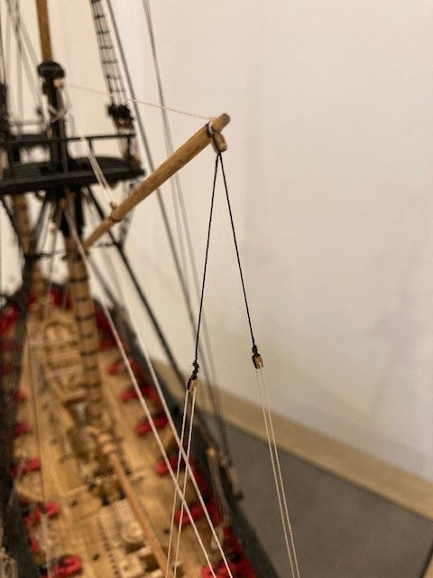
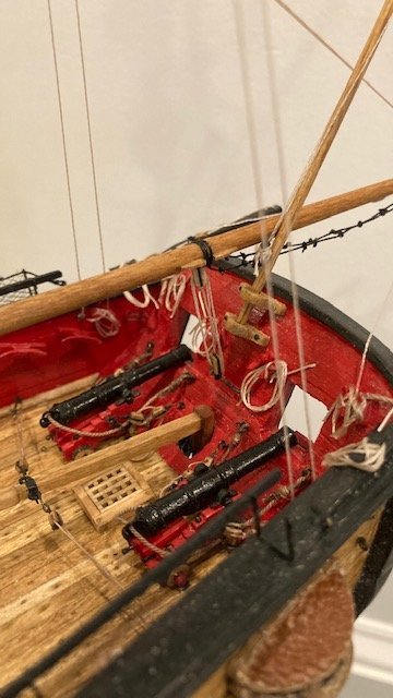
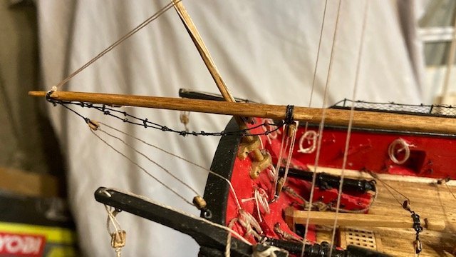
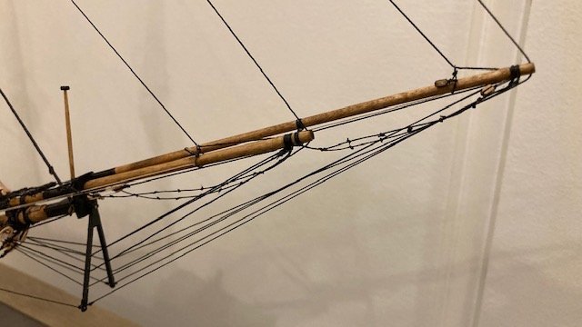
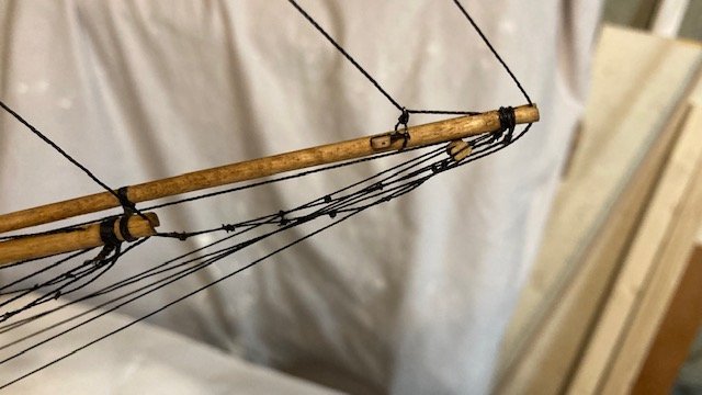
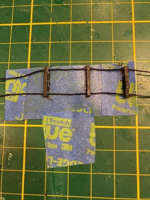
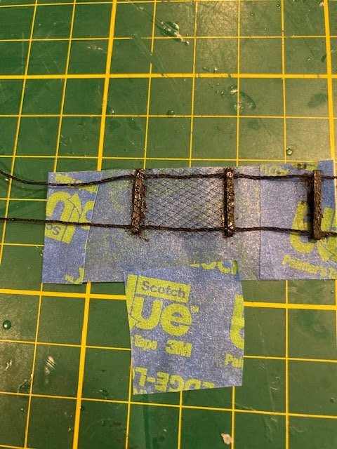
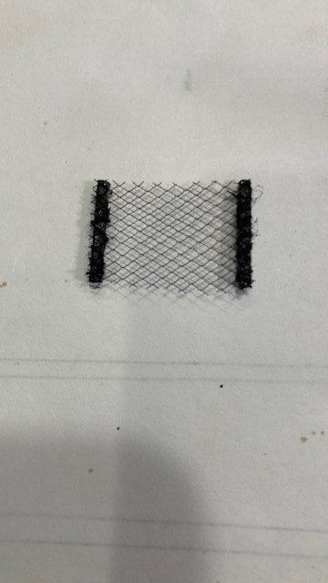
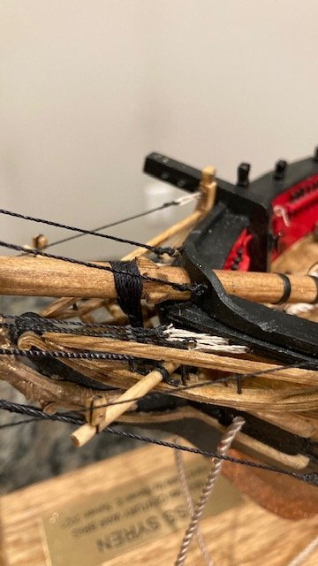
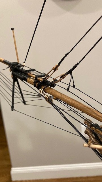
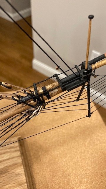
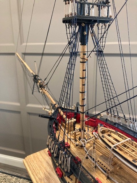
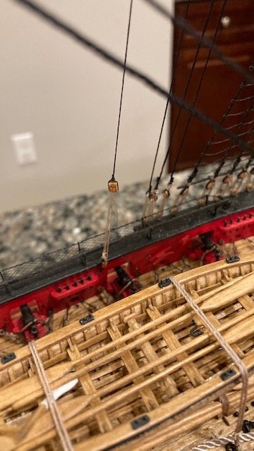
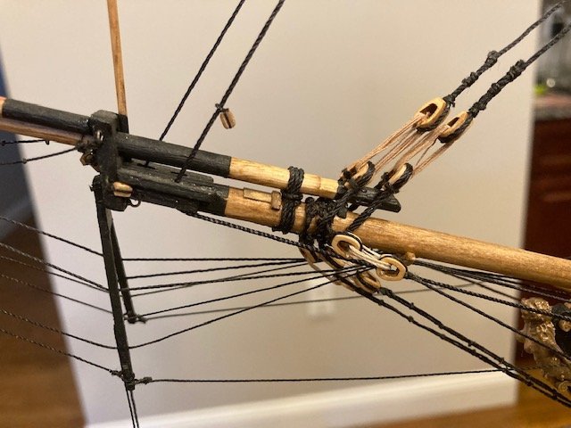
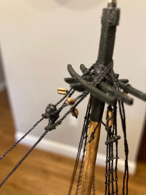
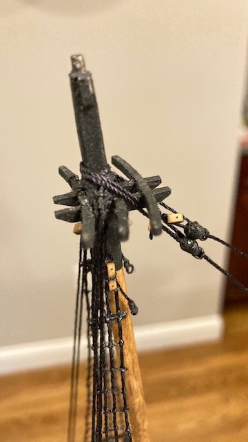
Well, I thought I would add that I'm a year and eight (8) months into my build - tedious work and attention to detail requires time and a lot of patients. Made progress on the standing rigging. Secured the fore and main topgallant mast/pole and rigged the shrouds (.018 black) as per the instructions. I cut a 13” length of .018 line for the fore pair of shrouds and a 26” length of line for the aft pair of shrouds. The aft-most shroud (main topgallant backstay) was set up with an eye and a lanyard (.008 tan) attached to the eye bolt on the main channel. The main royal backstays (.012 black) and tackles were next, followed by the main royal stay (.012 black) and the main topgallant stay (.012 black). The fore royal backstay running tackles were difficult to belay to the pin rail because of the long boat. In hindsight, I think it would have been better to lash down the long boat later. I finished the fore topgallant stay and the fore royal stay. I had previously reeved these lines through the fairlead and dolphin striker and set up the lanyard back in Chapter 16 (see March 18th post, Page 3), so all I had to do was seize the lines around the fore gallant mast and the fore royal pole, respectively, and tighten up the lanyards. This turned out to be a good idea. I made the bowsprit horses next. I hadn’t seen much discussion in other build logs on how to make these. However, I did take a page out of JesseLee’s build log and decided to pre-rig the horses off ship. I improvised here, as follows: 1. Rather than use 1/32” x 1/32” strips/battens, I used 1/16” x 1/16” strips, cut about ½” long. 2. Instead of lashing the strips, I drilled a hole at each end of a test strip to reeve the .018 line. The ends of the test strip split when drilled. To avoid this, using the test strip as a template, I marked the location of the holes for three battens on a longer strip, drilled the holes, and then cut the individual strips. 3. Sanded the strips to reduce them somewhat in size. 4. Set up the three (3) battens and horses, spaced apart as per the Sheet 5, on a piece masking tape to hold them in-place. 5. Cut a square piece of netting to fit between the aft battens, placed it on the battens, and applied CA to secure it. 6. Removed the .018 line and lashed the netting to the battens with black thread. 7. Made an eye on the bow end of each horse. Removed the eyebolts from the bowsprit cap, attached them to the eye, and re-inserted the eyebolts into the bowsprit cap. 8. Reeved the loose end of the horses through the battens and the eyebolts on the splash guard and attached a clip to each loose end to hold the lines taut. 9. Slid the battens into their proper positions and applied CA to secure them. 10. Lashed the netting to the horses with black sewing thread. 11. Made an eye at the loose end of each horse. Note: Cut the line long enough to allow for the horses to be pulled upward when tied to the fore stay with the “leg.” 12. Removed the eyebolts from the splash guard, attached them to the horse eyes and reinserted them into the splash guard. 13. Cut a short length of .018 line and seize it to the fore stay just above the closed heart. 14. Looped each loose end of the leg around the horse, applied tension to the horse by lifting the leg, and applied CA to hold it. Seized each leg to the horse with black sewing thread. This procedure worked well for me. The most difficult part is tensioning the horses and seizing the “leg.” The leg pulled down the fore top mast stay slightly. Overall, the horses aren’t perfect, but I’ll accept some imperfection. I wanted to move on to the jib stay and flying jib stay, but I ran out of .018 black line, so I'll have to order more from Model Expo. In the meantime, I think I’ll start on constructing the boom and gaff. Stay tuned for progress.
- 157 replies
-
- 2
-
-
- model shipways
- syren
- (and 1 more)
-
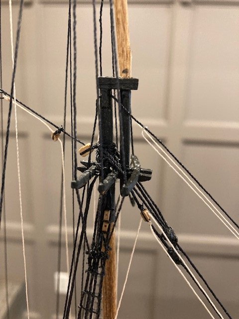
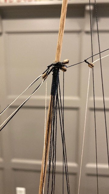
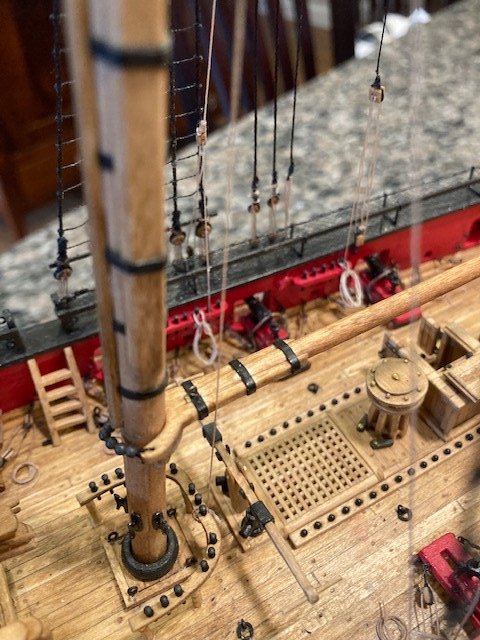
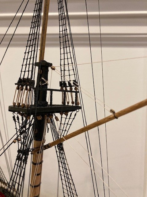
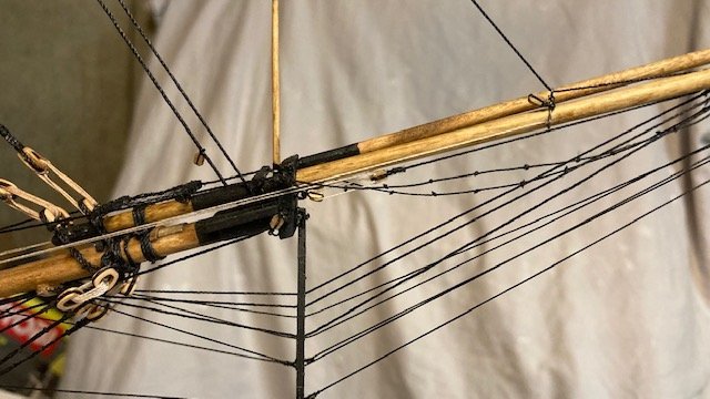
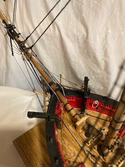
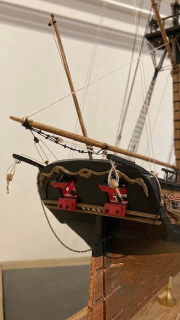
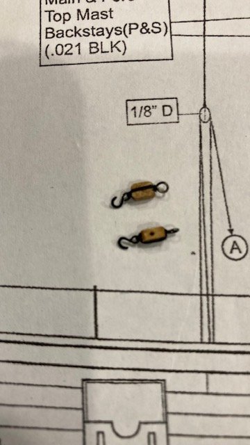
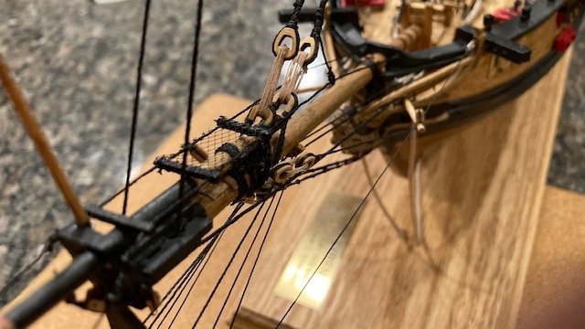
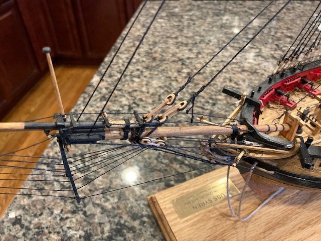
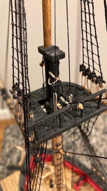
Set up the claws temporarily to determine the length .021 black line for the main topmast backstays. I looped the loose ends of the line around the top mast head and then around the claw and allowed enough length for turning the deadeye and seizing the line. I seized the line around the topmast head – starboard side first followed by port side. I’ll complete backstays when I receive my order of 2.5mm deadeyes. In the meantime, I made the mouse for the .028 black main topmast stay and the .021 main topmast preventer stay a la the main stay (see July 12 post on Page 4). I had to ream the 5/32” block rigged to the fore mast below the catharpins in order to reeve the .028 line through the block. Unfortunately, in reaming the block, it split in half. So, I had to lash a new block to the mast. A word to the wise: make sure the .028 line will pass through the 5/32” block before lashing it to the mast. I decided to add the 3/32” single block for the main topmast staysail down haul (refer to Sheet 7) to the main top mast stay before setting it up with a lanyard. I also added the 3/32 single block for the main topmast staysail hallard on the port side of the main topmast stay above the mouse. I made an eye at the end of the block to tie the hallard to later. The main topmast preventer stay was next. I had to ream the block rigged to the fore top in order to pass the .021 line. Fortunately, this was done without incident. I added the two 3/32” single blocks for the main topsail braces and the two 3/32” single blocks for the topgallant braces above the mouse. While waiting for my 2.5mm deadeyes to arrive, I decided to set up the main topmast stay and preventer stay before rigging the topmast back stays. I created an eye on the end of each stay per the instructions. I used .012 tan line for the lanyards. I tied one loose end to the stay eye and then reeved the other end though the eyebolt in the deck “abaft of the fore mast.” I made three (3) passes with the line, tied it off at the eye on the stay, secured it with CA, and trimmed the end. The lanyards aren’t quite equal in length. Set it up the fore topmast preventer stay (.021 blk) with a mouse around the fore topmast head. Reeved the loose end through the bees on the starboard side, set it up with an eye and lanyard, and lashed it to the eyebolt on the starboard side of the bow – a bit tricky. Added the 3/32” single block just above the jibboom for the fore topmast staysail downhaul. Seized a 3/32” single block on the starboard side of the topmast stay above the mouse. This block is for the fore topmast staysail hallard. Fore topmast stay (.028 blk) was set up like the fore topmast preventer stay. The loose end is reeved through the bees on the port side and set up with an eye and a lanyard. I received my order of 2.5mm deadeyes, so its on to rigging the topmast backstays. I set these up same as the topmast shrouds. With that done, it’s time to secure the fore and main topgallant mast/pole and add the top gallant shrouds. Stay tuned.
- 157 replies
-
- 3
-
-
- model shipways
- syren
- (and 1 more)
