
HOLIDAY DONATION DRIVE - SUPPORT MSW - DO YOUR PART TO KEEP THIS GREAT FORUM GOING! (Only 24 donations so far out of 49,000 members - C'mon guys!)
×

abelson
-
Posts
467 -
Joined
-
Last visited
Content Type
Profiles
Forums
Gallery
Events
Everything posted by abelson
-
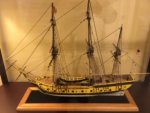
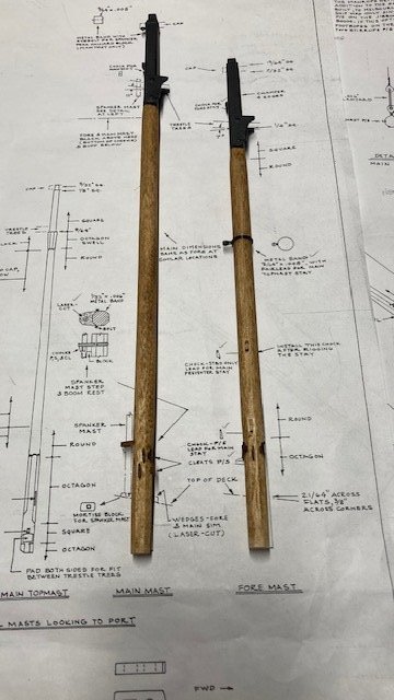
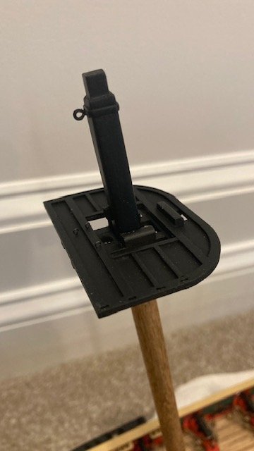
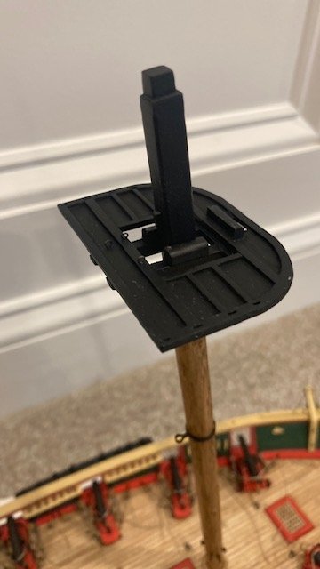
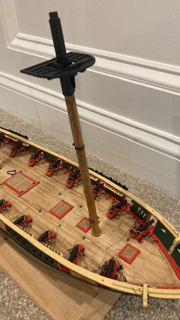
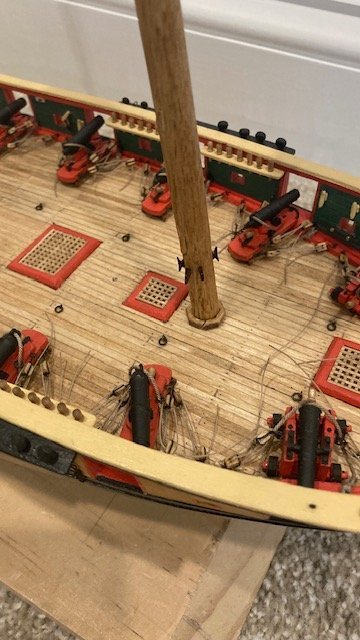
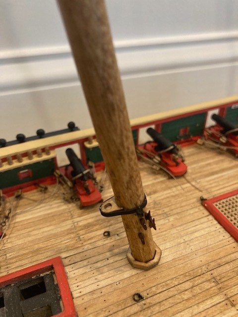
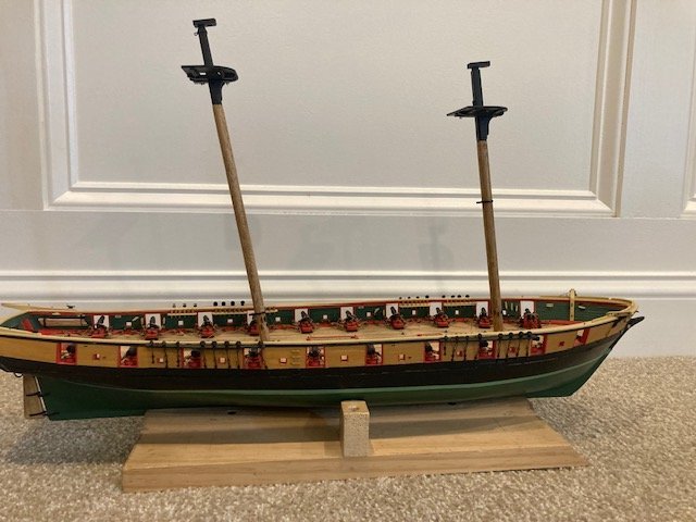
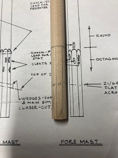
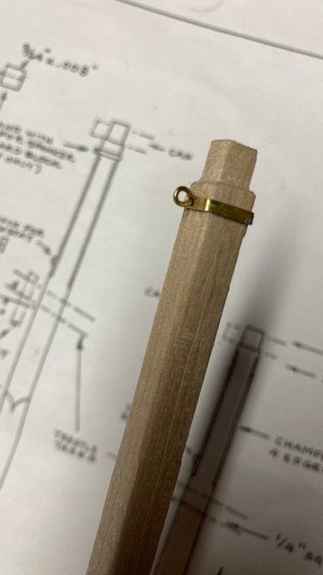
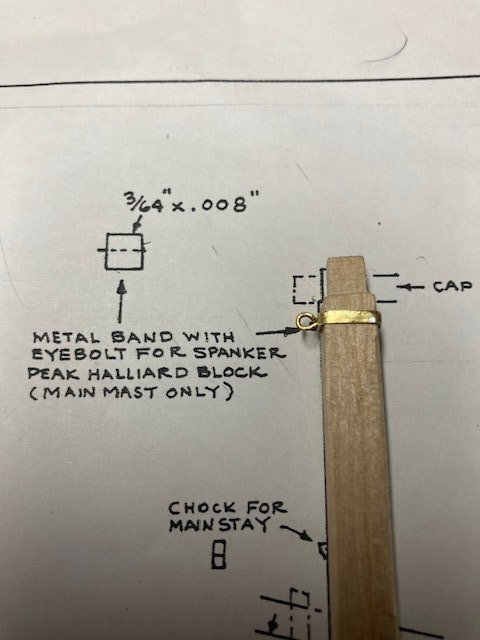
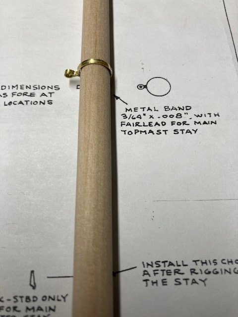
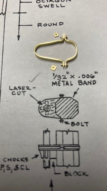
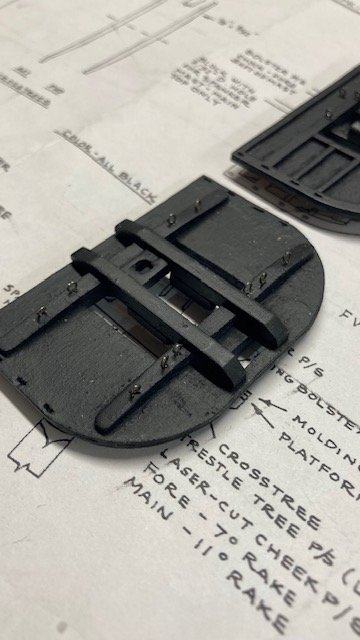
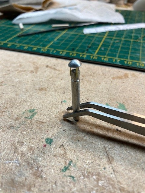
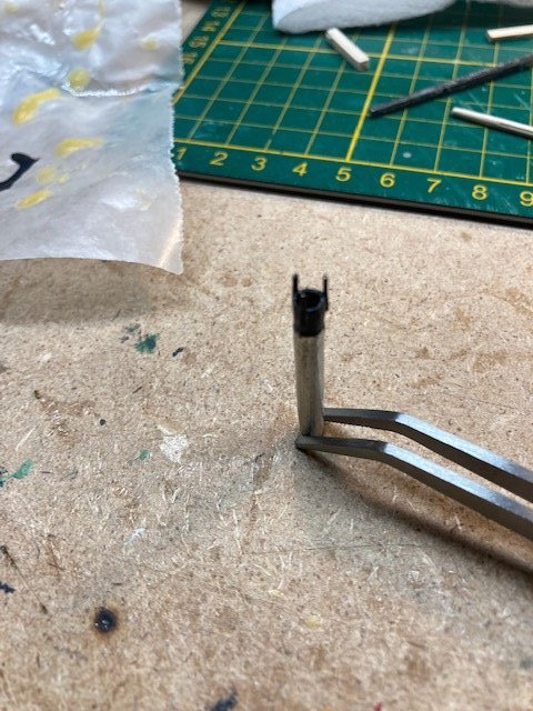
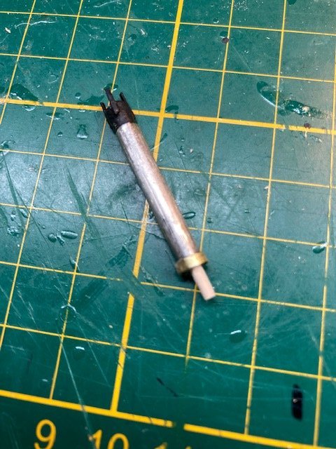
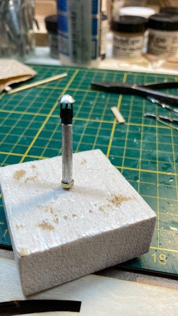
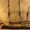 The Fore and Main Masts are fashioned from 3/8” dowel. For the octagonal section, I made pencil marks on the dowel using a strip of wood the approximate width of the octagonal flat surface. This served as a guide for creating each octagonal surface. I used a file and sanding block. The squared, tapered section requires a lot of sanding and filing, as does the notch for the cap. The Fore Mast has a round metal band with a fairlead (ring) for the main top mast stay. I used 1/64”x 1/16” brass strip for the band. I crimped the band around a round needle nose plier to form the ring and then bent band around the Fore Mast. I crimped and cut the ends. I soldered the cut ends together, filed the rough edges smooth, and slipped the band over the mast. The hardest part was soldering the ends. The fairlead has to be large enough to pass a .028” dia. rope (Note: the plans call for this line to be .027” dia. The kit is furnished with .028” dia. rope). The Main Mast has a square band with an eyebolt for the Spanker Halliard. I used 1/64”x 1/16” brass strip for the band, which was bent around the squared section of the mast and finished a la the Fore Mast band. The band was placed over the mast and positioned as shown on Plan Sheet 4. A hole was drilled in the band for the eyebolt. I formed the eyebolt from .020” brass wire, flattened it slightly, and glued it into the pre-drilled hole in the band. Fashioned the metal bands for the Spanker Mast from 3/32”x 1/16” brass strip as shown on Sheet 4. For the faux bolts, I used brass pins. I inserted the pins in my Dremel and filed down the heads and shafts to a smaller scale. The bands were spray painted black. The faux bolt nuts were made for the same strip. I drilled a hole in the strip and then cut it down to scale. I pinned 5.5mm cleats to the masts at the locations shown on Sheet 4. The Crafty Sailor cleats come with a hole drilled through them to facilitate pinning them. Completed the Fore and Main Tops. I didn’t find much discussion on the Tops in other build logs. Maybe because they’re so simple to make, but the most difficult thing for me was drilling the holes for the dead eyes. The wood is thin and brittle. To prevent the wood from splitting, I applied a little CA to the areas to be drilled. I made a photocopy of the Top and used it as a template. The holes are more oblong than round, so I drilled two .55mm holes at each deadeye location and then removed the wood between the holes with an x-acto knife. Even with the CA, the wood still split in some locations. There are two rows of two blocks attached to eyebolts on the underside of the crosstrees, port and starboard. These blocks are for the leach lines and bunt lines. At the Fore Mast Top all blocks are 1/8” double. At the Main Mast Top the inboard blocks are 1/8” single and the outboard blocks are 1/8” double. This is not obvious from the plans because the Main Mast Looking Aft on Sheet 6 shows a double inboard block but Detail 6-H notes that the inboard row of blocks are singles. There are also two 1/8” double blocks forward of the mast. These blocks are for the course yard truss falls, as shown in Detail 6-G on Sheet 6. The Fore Top and Main Top each have 3 eyebolts aft of the mast. These are for the Topgallant Yard Tye Halliard (Detail 6-D) and Top Mast Lifts Reef Tackle (Detail 6-F). Note: The Fore Top also has an eyebolt for the Main Royal Stay (Detail 5-F). I drilled holes for all of the eyebolts and then primed and finish painted (flat black) the tops. I decided to finish the masts below the cheeks “bright” rather than “buff.” I did this because I had pinned the cleats to the unpainted mast and wanted to keep the cleats natural. I thought it would be too difficult to paint around the cleats. I used Minwax Pre-Stain, followed by Minwax Golden Oak stain, and finished with one coat of polyurethane. The area of the masts above the cheeks was primed and then spray painted flat black. I added eyebolts (made from 28 gauge annealed steel wire) to the mast tops. Permanently attached the metal bands for the Spanker Mast – this was easier than anticipated. The tops have been temporarily placed on the masts for photo purposes. Next on the To Do List, the Spanker Mast and Fore & Main Top Masts.
.jpg.809025f868504fb306f9da97e7020d8f.jpg)
.jpg.4b999fa6a5e8d8ce2421bd9c63257b41.jpg)
.jpg.e47f86178e50a293a03f7e35ca37287f.jpg)
-
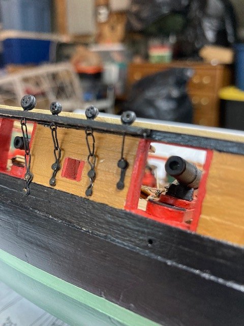
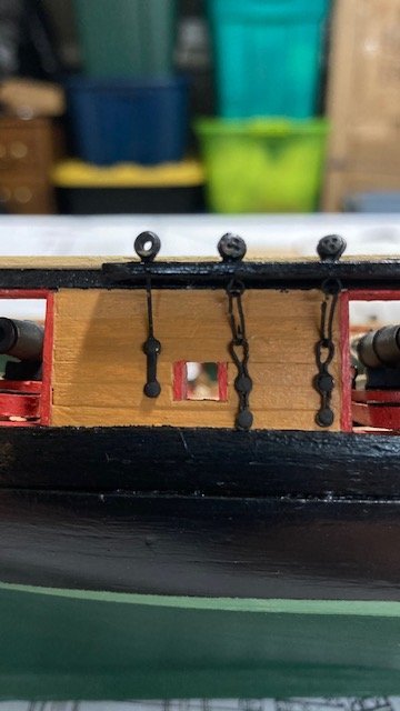
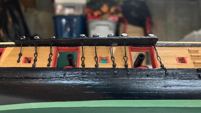
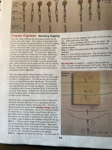
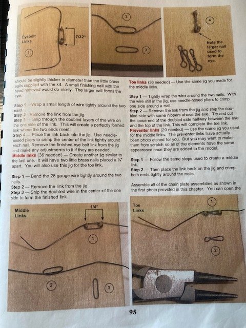
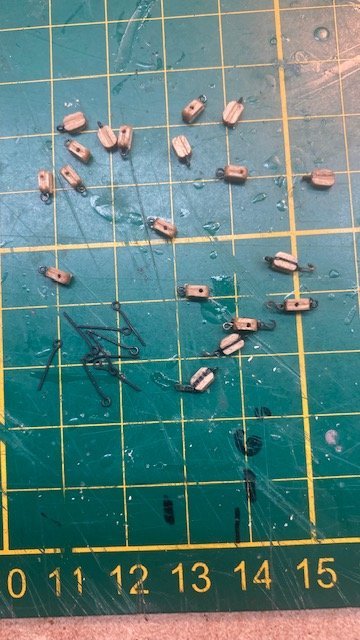
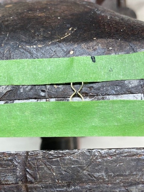
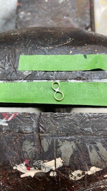
I was not successful in finding 9/32” x .28” flat brass rings for the deadeye strops, so I decided to revert to the Syren Instruction Manual for making the chain plate assemblies (see photos). The instructions are concise and easy to follow. I used 28 gauge (.41mm) annealed steel wire for all chain plate components and CA for securing the wire. As always, patience is a virtue here. By trial and error, I found that a 2” length of wire was ideal for stropping the 3.5mm deadeyes. I scaled the length of the middle link, toe link, and preventer link from the plans and set up my jig accordingly. Completed the 20 chain plates for the 1/8” deadeyes, the 8 chain plates for the 3/32” deadeyes, and the 4 chain plates for the topgallant backstay – this is the first step in beginning the standing rigging. I’m not there yet but wanted to accomplish this task now rather than later. After connecting the middle link with the deadeye strop and toe link, I aligned the cut ends of the middle link and applied a little CA to the joint. I filed the trimmed ends of the strops to even them out. The preventer links were pinned to the hull with brass pins. Note: The brass pins provided with the kit are too big, so I will use the brass pins left over from my Syren build (see photo). The chain plates are a little shorter for the 3/32” stropped deadeyes, so I had to adjust the jig for making the middle link, toe link, and preventer link. For the topgallant backstay chain plates, I used 28 gauge wire for the rod. I wrapped the wire around a 3/32” bullseye and formed an eye at the opposite end. I use 1/4” brass backing links for the preventer link. To get the proper angle of the chain plates, I placed a photocopy of the links onto the bulwarks and aligned it with the notches in the channel. Some minor adjustment was necessary. Hopefully, the angle of the chain plates will coincidence with the angle of the shrouds. With the chain plates in-place, I added the keeper strips to the channels, painted them black, and finished them with a coat of polyurethane. Up to this point, except for the Quarter Davits and Hammock Rails and Stanchions and building the Ship’s Boats, the build is complete through Stage 5 of the Instruction Manual. Now, on to the Stage 6 - Mast and Spar Construction.
.jpg.d0a2ca32078094a2cc6e8ac6f10dd5c6.jpg)
-
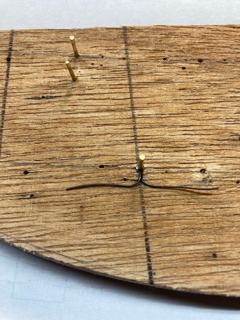
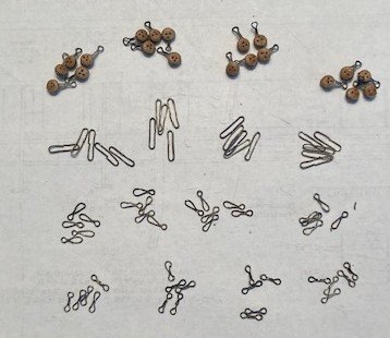
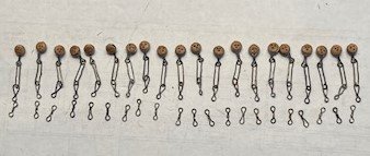
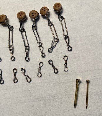
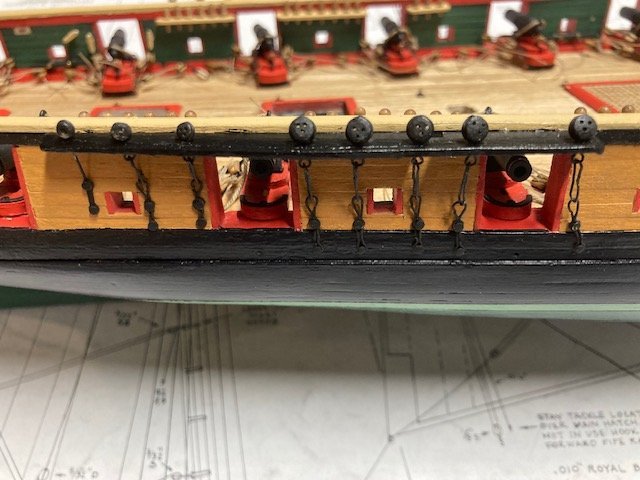
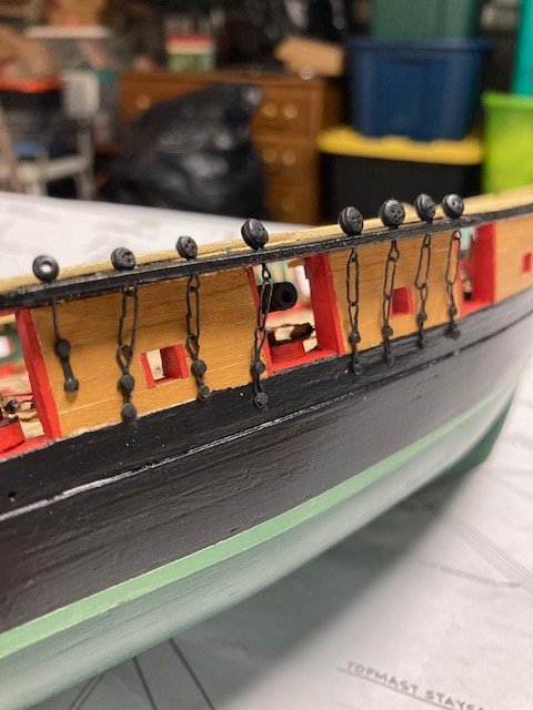
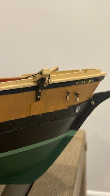
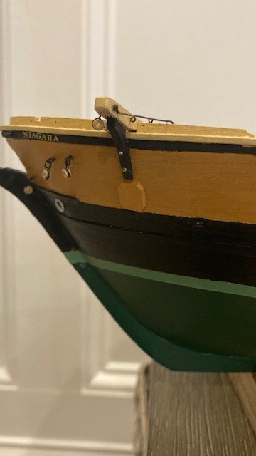
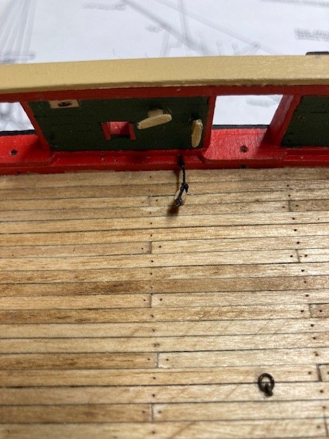
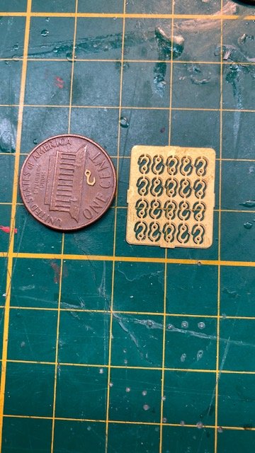
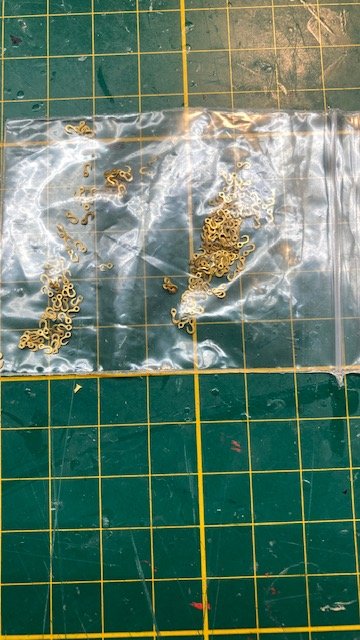
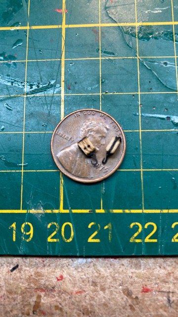
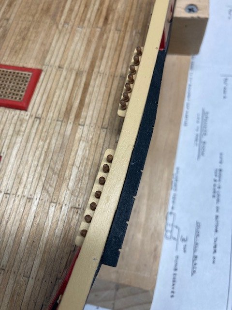
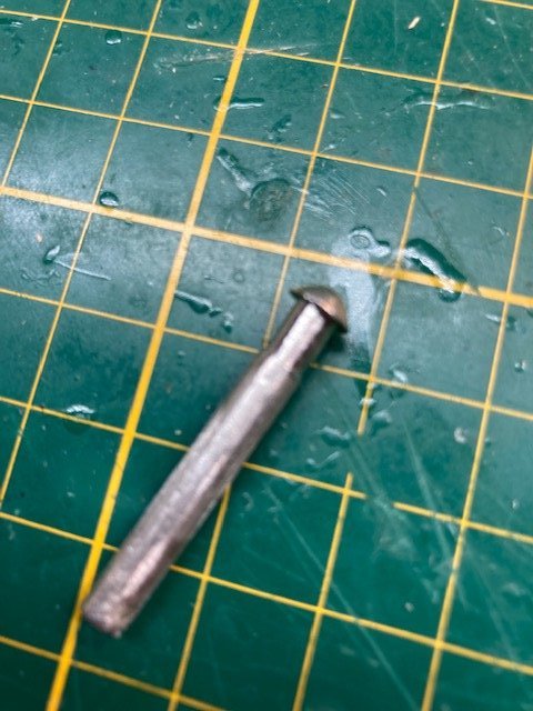
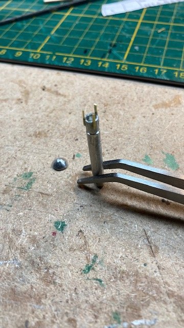
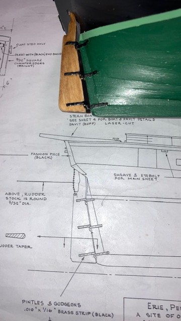
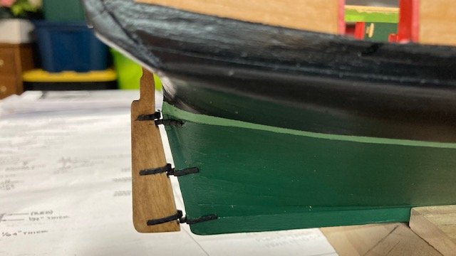
Permanently attached the pin rails. Moving on to the Davits and Catheads. I had previously made the Davits (see post #31). I glued them onto the rail and secured them with brass pins for visual effect. The pin heads were filed down. The cleats are 7mm pear wood – left unpainted. Speaking of cleats, I had read in another build log were the 40 kit supplied cleats aren’t enough. Counting all the ones on the mast & boat davits & bowsprit, there are at least 40 cleats. Also, I notice on the plans that the cleats for the masts are smaller than the kit supplied 3/16” (8mm) lead cleats. So, I ordered some 5.5mm and 7.5mm pear wood cleats from Crafty Sailor. For the Catheads, I decided to attach the bullseyes to the Catheads before attaching the Cathead to the rail. I had read about the troubles some other builders had with drilling out the kit supplied deadeyes to make them bulleyes, so I purchased some 2.5mm bullseyes from Model Shipways. A la the tiller blocks, I used .008 black line and made an eye for attachment to the eyebolts on the Cathead (see photo). I glued each Cathead to the bulwark and added a couple of brass pins for visual effect. I made the rod for the Cathead using 28 gauge annealed steel wire. The plans don’t detail how the rod is attached to the Cathead. I attached the rod to the chock rail as shown on Sheet 3. I formed an eye on the opposite end of the rod and attached it to the Cathead with a brass pin. On the replica ship, the rod appears to be attached by a rod that passes through the Cathead and is secure with a nut (see photo). The laser cut knees were a little tricky to install. I had to shape and file them to get a proper fit and shorten the top to clear the faux sheaves. I glued them to the hull and then secured them with brass pins. Moving on, I added an anchor chafing block below each knee (not shown on the plans). Lastly, I removed three eyebolts from the port and starboard side of the bow, seized bullseyes onto them, and reinserted them into the bow. These bulleyes are for the jib stay and back rope lanyards. Note: For what it’s worth, I rely on the plans more than the Instruction Manual, but I decided to review the Manual to see if I had missed anything up to this point. Stage 4 of the Manual covers the mounting of the hull to a baseboard. While I had already fashioned the display board and purchased brass pedestals, I did notice that the Manual says “two brass pedestals and a baseboard are supplied.” The kit is not supplied with these, and it would have been unusual if they had been supplied. I reached out to Model Shipways and they confirmed that the Manual was a miss print. Next, I decided to strop the deadeyes. I found some brass rings left over from my Rattlesnake kit from 1973. These are perfect for stropping the 3/32” deadeyes. Unfortunately, I don’t have enough of them, and model Shipways doesn't sell them anymore. I reached out to them and they suggested contacting Piel Craftsmen in Norfolk, MA (see photo). They do not supply them, although they have an extensive fittings catalog. The deadeye assembly would be simplified with the 9/32” rings if you could find them. Going back in time, in the 1976 Model Shipways catalog (see photos) the strop rings sold for $.25 a dozen. I also found some 1/4” brass backing links which would be perfect for the chain plates - they sold for $.20 a dozen. Unfortunately, I only have 23 of them. In the meantime, I’ll have to contemplate how to strop the deadeyes. Stay tuned.

.jpg.b5464d0dbc1afc67b081d4a18e40057a.jpg)
.jpg.c45920bf6eb5440de38a89761aa944d9.jpg)
.jpg.f0628843f26ba54c18345d81ba030546.jpg)
.jpg.34e1a48493fdd7521666e075a362515d.jpg)
-
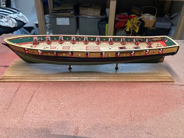
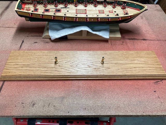
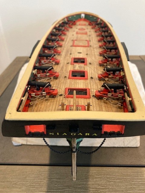
Except for coils, completed rigging the cannons. At this stage, I think it’s a good time to mount the ship on a permanent display base. The base is 1”x 6”x 24” red oak (purchased at Lowes). The edges were routed. The board was pre-stained with MinWax Pre-Conditioner and finished with MinWax Golden Oak and one coat of polyurethane. The pedestals are from Model Expo. They had to be filed down to fit the keel. I haven’t found much discussion on display boards in other build logs - the size is a matter of preference. I had previously drilled holes in keel for the mounting screws. The ship is taking on a finished look albeit there’s a long way to go. I updated my To Do List. I rigged the tiller as per Detail 5-L on Sheet 5. After reviewing TomE’s build log, I replaced the kit supplied small eyebolt in the waterway with a larger one to accommodate the 3/32” single block for the tiller rigging and the 1/8” double block for the Spanker Boom. For the blocks, I used .008 black line. I made an eye for attachment to the eyebolts. The larger eyebolts were made from 24 gauge brass wire. I realized I needed to seize the tiller tackle to the 3/32” block at the waterway, so I added a small eyebolt to the block. I seized an 8” length of .012 tan rope to an eye on each of the 3/32” single blocks for the tiller tackle. I stropped the two 3/32” single blocks to the tiller. I fashioned the tiller blocks with an eye that slipped onto the tiller. The plans do not show where on the tiller blocks should be placed. Some build logs place them aft of the aft bitts and some forward of aft bitts. By trial and error, I decided to locate them forward of the aft bitts so as not to interfere with belaying the spanker boom sheet to the aft bitts. The plans say to belay the tackle to the tiller, but it isn’t clear where on the tiller and how. I did some research and found that the loose ends of the tackle were turned around the tiller and not belayed. The turns around the tiller provided friction to take away some of the force of the sea on the tiller. The tiller could be controlled by pulling on the loose ends of the tackles rather than controlling the tiller by hand. Be that as it may, I made a few turns around the tiller and left the loose end hanging. While reviewing build logs, I was reminded that I need to notch the aft channels to receive the quarter boat davits. So, I removed the channels, which were not yet permanently installed, and notched them. AT this point, I'm approximately 8 months into the build. It's always reassuring to look back on past photos to realize how far you've come. Next up, permanently adding the cat heads and davits.
.jpg.a467c34d05bc93a3cac9d6f26068cd89.jpg)
.jpg.3bb4cc07291ecc599b59517b71eb10df.jpg)
.jpg.f37faafcd30077963720358252e49e18.jpg)
.jpg.37fdf14b4a5884be078b89a36d7acd21.jpg)
-
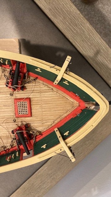
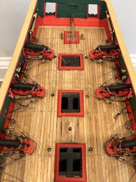
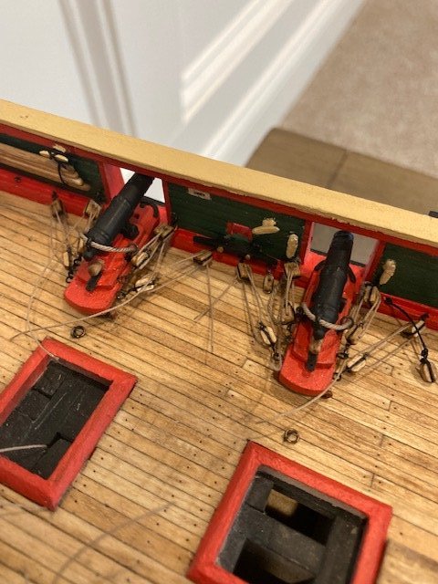
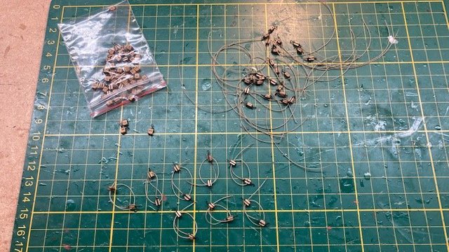
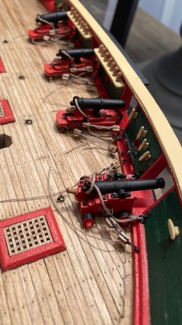
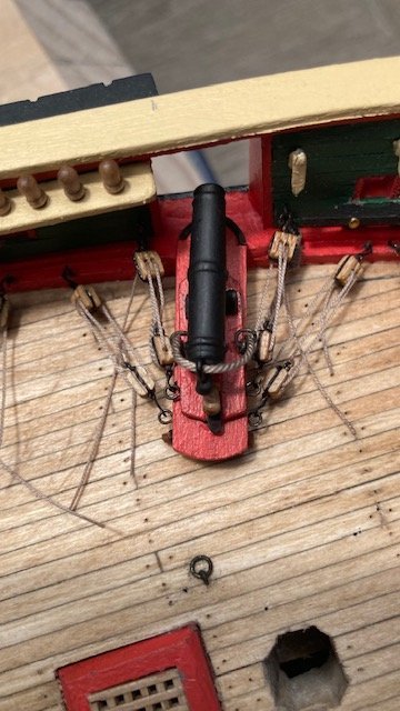
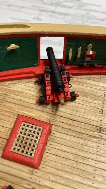
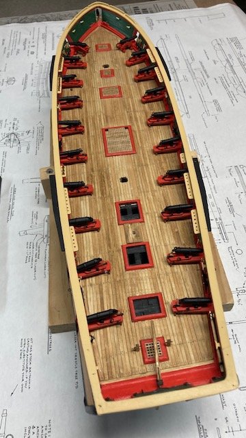
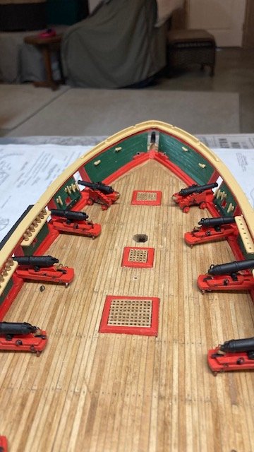
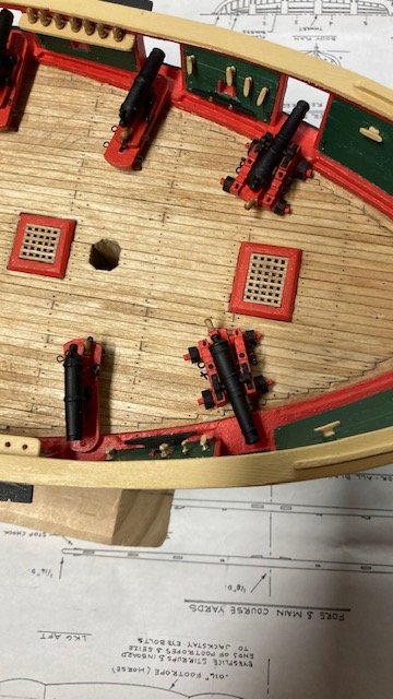
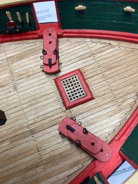
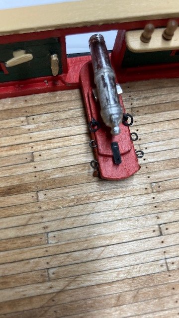
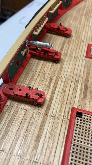
Slow progress stropping the blocks for the carronades and long cannons. Completed all of the 80 double blocks (1/8”) with 3 mm hook. Have completed stropping 48 single blocks (1/8”). I added a 6mm eyebolt to the single block for the seized tackle. I found this easier than creating a seized becket. As with the double blocks, some of the blacking comes of the hooks, so I touched them up with black paint. I ran out of 6mm eyebolts, so I had to order more from Model Shipways. In the meantime, I decided to rig the long cannons. I applied CA to the pin that I had added to the long cannon and then set it in a pre-drilled hole in the deck. With a toothpick, I added a little CA under the foremost trucks to further secure the long gun. For the breach line, I cut a 3” length of Syren .035 tan rope. I wrapped each of ends around a 1/8” ring attached to a small eyebolt (prepared previously), seized each end using sewing thread, applied a little CA to the thread, and trimmed the ends. Next, I glued the eyebolts into pre-drilled holes in the bulwark. Note: wrap the breach line around the cannon before securing the opposite end eyebolt to the bulwark. Some of the blackening comes of the rings while reeving the breach line and tends to dirty the line, but I think it makes the line look aged, so okay. The breach lines are a little tricky to wrap around the end of the gun. I made up the gun tackles next. For the gun tackles, I cut a 3” length of Syren .012 tan rope for each gun tackle. Tied one end of the rope to the eyebolt on the single block with a simple half hitch, applied a little CA and trimmed the end – no seizing here, kept it simple. Reeved the opposite end through the double block, single block, and double block. Decided to forego frapping the tackles - the plans don’t call for this anyway. Attached the block hooks to the rings on the gun cheek and the eye bolts in the waterway. Tightened up the rope and applied a little CA to the double block to secure the rope. The tackle ropes will eventually be cut and glued to the deck and rope coils will be added. I’m not planning to add the train tackles. BTW, the 1/8” blocks look a little out of scale to me - just saying. Moving on the carronades, I secured the carriages to the gun port sills by applying yellow glue under the carriage at the pin and inserting the pin into the hole in the gun port sill. I did three carriages at a time port and starboard. While waiting for the glue to dry, I continued stropping the single blocks. For the breach lines, I found it easier to rig them with the guns off-ship. I had prepared the 1/8” ring and small eyebolt assemblies previously. I seized the .012” rope to a 1/8” ring and then cut the rope about 3” beyond the ring. Next, I reeved the rope through the rings on the sliding carriage base and carronade, seized the rope to the 1/8” ring and eyebolt on the opposite side, trimmed and applied a little yellow glue to the eye bolts and inserted them into the pre-drilled holes in the bulwark. The carronade train and gun tackles were made a la the long gun tackles. They’re fairly easy to install. The importance of adequately securing the eye bolts cannot be overstressed, as I had a few come loose while hooking the blocks. I’m continuing the process of gluing the carriages three at a time, stropping single blocks, and making up the tackles- steady as she goes.
.jpg.c3b21b36b6e88d3b15e88d0bac504807.jpg)
.jpg.f649fa20ae35fa730ef40327b7922b86.jpg)
.jpg.26d54fbdbba1db0fa6fae68dd311390c.jpg)
.jpg.e338fe9e34cf19e70f00c47ed442482e.jpg)
.jpg.9bbac513d07bb8ed9a89178e046cc3b7.jpg)
.jpg.ca9673ff7f61be782b9f3a8859ceb8a3.jpg)
.jpg.4edf0d009db525dfbdd504b1f9776755.jpg)
-
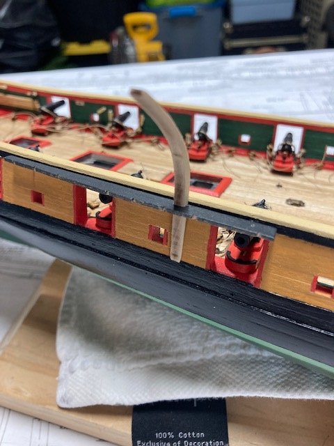
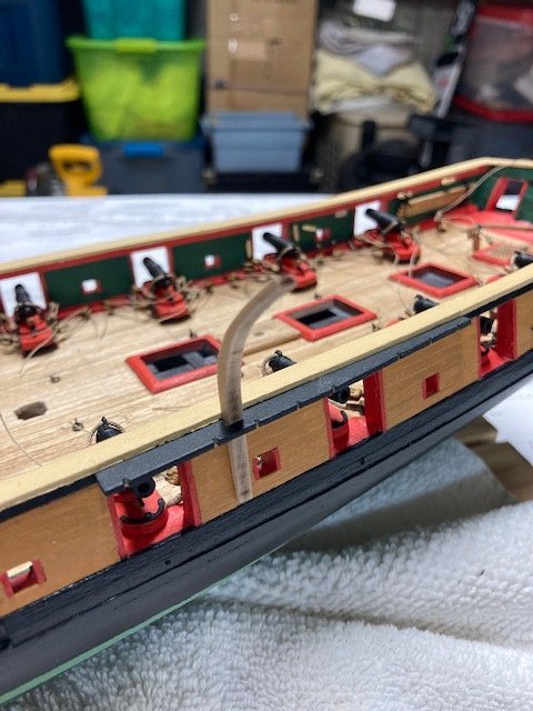
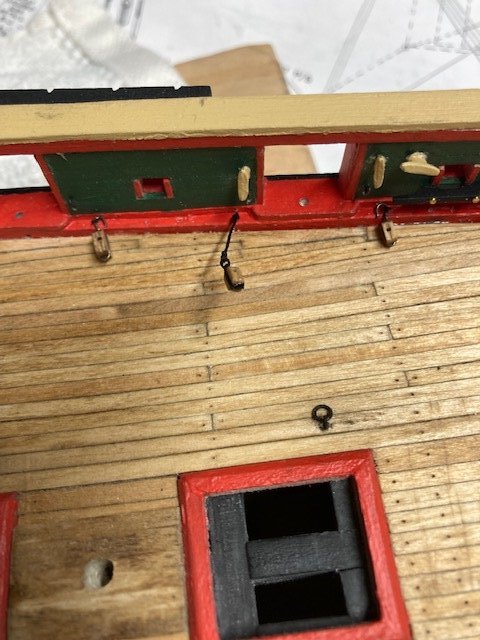
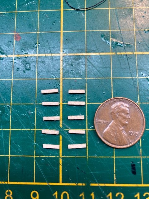
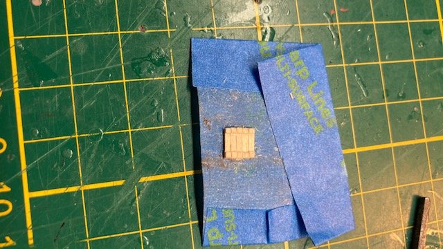
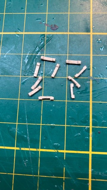
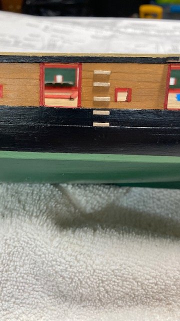
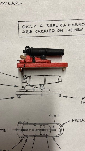
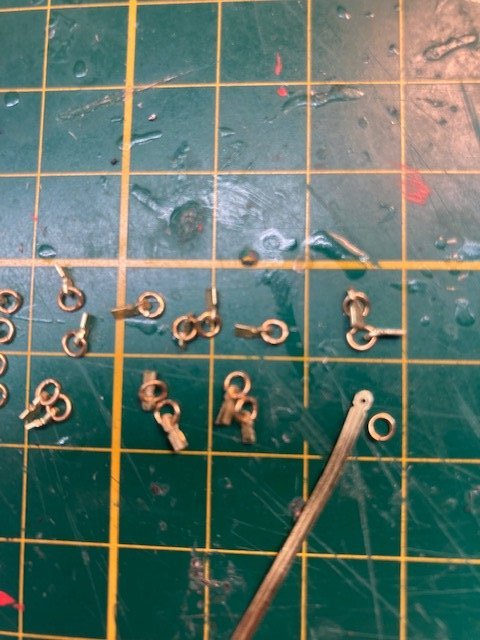
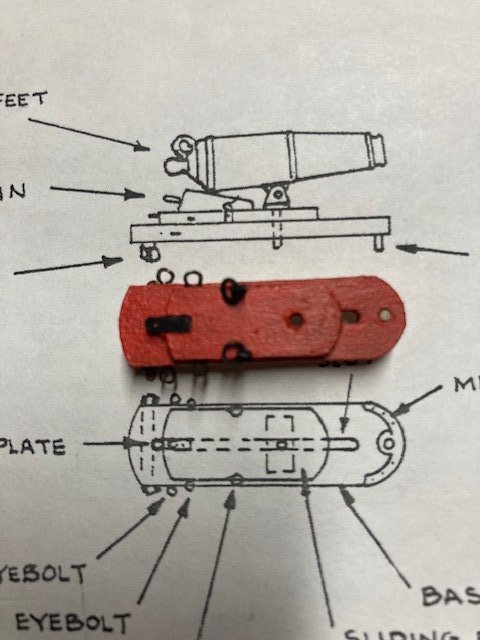
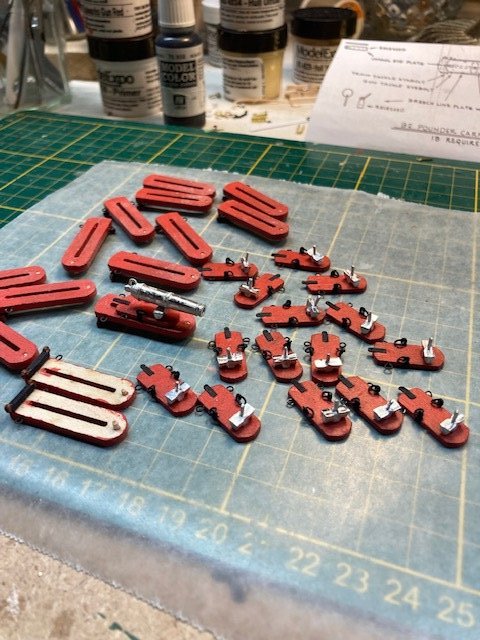
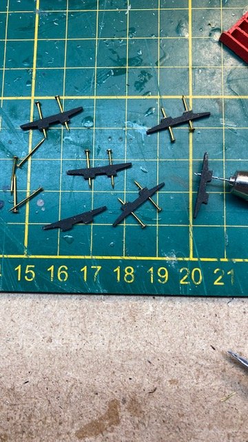
Continuing with the build, I decided to add the metal plate at the end of the carronade base. I formed a piece of 26 gauge annealed steel wire around the front edge of the base and then flattened the wire on my vise using a hammer. The plate was bent slightly to match the radius of the base and ends were trimmed. The pin hole was painted black to simulate the metal plate shown on the carronade detail. Drilled holes for all the eye bolts for the carronade and long cannon tackles. Suggestion: Drill the holes and install eye bolts before attaching the mooring cleats and belaying rails. Reviewed the Rigging Profile (Sheet 5) for rigging that gets attached to the other eye bolts that were added to the waterway previously. Added the following blocks P&S: 3/32” single block for the Royal Backstay tackle (seized line) 1/8” single block for the Top Gallant Stay tackle (seized line) 5/32” single block for the Topping Lift tackle (hooked) and 1/8” single block for the Vangs tackle (hooked). With all the eye bolts in-place, I stated removing the photo etched 3mm hooks purchased from Crafty Sailor. If my count is correct, there are 160 hooks required for the carronade and long gun rigging, not counting the train and in-haul tackles which total another 40 hooks. The Crafty sailor hooks come 20 per package. Each hook has to be filed to remove the burrs. All of the hooks were blackened. Moved on to stropping the blocks. As per the plans, there are four 1/8” single blocks and four 1/8” double blocks required per carronade and two 1/8” single and two 1/8” doubles required per long cannon. The 1/8” single blocks have a hook and a seized rope that is reaved through the double block and the single block and back through the double block. I used .008” black rope for stropping the blocks. I find many builders like to use Syren blocks. They do look better than the kit supplied blocks, but I've always had success with the kit supplied blocks so I'm sticking with them. I passed the rope through the eye of the hook, tied an overhand knot, and wrapped the line around the block. This is easier than the more involved and detailed process if creating a seized becket for the hook. I applied CA to hold the line in-place and trimmed it at the top of the block. I found that some of the blackening comes off the hook, so I touched up most of the hooks with black paint. Decided to take a break from the mundane, tedious task of stropping the double blocks to make the sea steps. Using a 1/32” square strip, I cut each step from the strip. The steps are very small and, consequently, difficult to handle. I cut the notch on the backside of each step using an x-acto knife. To even out the notches, I stuck the steps edge to edge on a piece of masking tape and filed them. I turned them over and rounded the ends with a sanding stick. They look authentic, but most of the detail is lost whence the steps are glued to the bulwark and painted. I applied one coat of paint to the steps, sanded them lightly, applied a second coat, and finished them with polyurethane. Now, back to the double blocks, 58 done, 22 to go.
.jpg.7a166e23b64e6cabf57c7fd239be44f0.jpg)
.jpg.69cf1c75f8e45fa8336dd3295a9f8912.jpg)
-
Thank you. I've been referring to your build log for guidance on the carronade rigging - very informative.
-
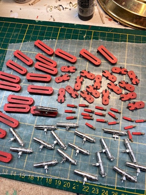
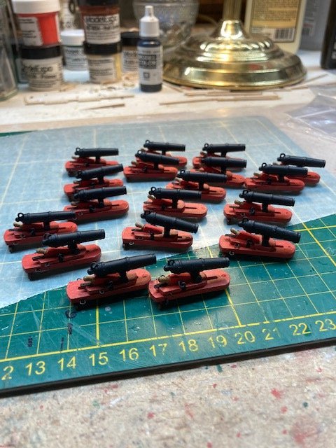
Continuing with the carronades, I made the quoins from 3/32” x 1/8” wood strip and 5/16” walnut belaying pins. The pins are a little larger than the scale of detail, but I think they look okay. I filed them down, shortened them, and glued them into a drill hole in the quoins. Painted the quoins red but left the pins unpainted for contrast. Cleaned up the rest of the gun barrels and then spray primed and finish coated (Testors flat black enamel) them. Finished the carronades and long guns. I added a locating pin in the front axle of each of the long guns to hold them in-place. I got this idea from xken’s build log. Now, it’s on to the rigging. Sheet 4 calls for the gun tackles to be .012” line but the kit is not furnished with this size line. Also, the breach lines are to be .031” line but, again, this line is not provided with the kit. There’s a discrepancy in the rigging line sizes between the plan sheets and the parts list – I pointed this out earlier in my build log. Consequently, I had to purchase some .012” and .030” tan rope from Syren Ship Model Company. I also purchased some 3mm hooks for the carronade and long gun tackles from Crafty Sailor. Before I get earnestly into the rigging, I want to check that I have installed all the eye bolts and rings for the rigging as well as other eye bolts that might be difficult to install after the carronades and log guns a rigged. In the meantime, following are photos of the completed carronades and long guns.
.jpg.70fe079971cee231dd9d402b20913cd8.jpg)
-
Thanks for your input, Steve. I'm retired and a widower, so I have the time to dedicate to the ship model. It keeps me busy in the winter - I'm not in hurry, although I do have the USS Constitution awaiting. Keep up the good work.
-
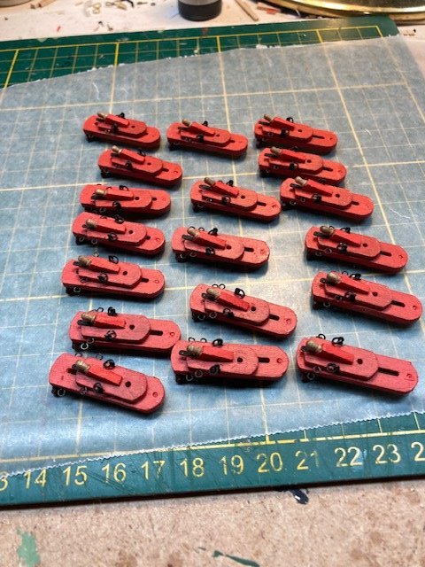
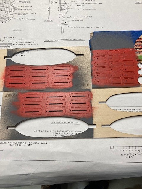
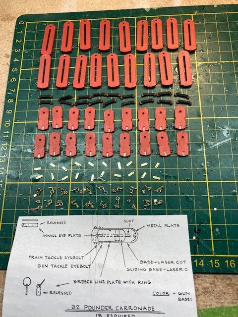
Started the tedious task of fashioning the carronade carriages and sliding bases. With the carriages and sliding bases attached to the laser cut board, I sanded them and brushed on two coats of Bulwarks Gun Red on the exposed side. I removed the carriages and bases and sanded and then painted the edges. I admit that it would have been easier to spray paint the carriages and sleds if I had wanted to take the time to find a matching spray paint. Anyway, with that done, I drilled holes in the edges of the carriages and bases for the eye bolts. I made the eye bolts from 28 gauge annealed steel wire. For the recessed breech line and inhaul eye plates, I used 1/16” brass strip. I drilled a hole in the end of each inhaul plate and inserted a 1/8” split ring (I thought the 3/32” split rings were too small – they actually scale less than 3/32”). The carronade detail shows a metal plate on the end of the carriages. These are not furnished with the kit, so I didn’t bother to added them. The roller castings were spray painted black and glued on the carriages with wood glue. For the breech lines and inhaul plates I carefully cut and filed a recessed slots in the platforms. Completed all the pieces for the carriages and sliding bases. Blackened the breech line plates with rings and the inhaul eye plates. Finished the carriages and sliding bases. Made the pins that fit into the gunports from toothpicks sanded down to size using my Dremel. Cleaned up the gun barrel feet to deburr them. Deburred one gun barrel and test fit it - 17 more to go. Still need to make the quoins.
-
I didn't round the underside of the bowsprit. I just rounded the edges. Once the bowsprit is in-place it won't be obvious that the bottom is not completely round. As for shaving off a bit of wood, again, it won't be that the noticeable that the bowsprit is slightly larger. Besides, in the process of creating the octagonal sections and shaping the bowsprit you will have naturally trim it down.
-
Thank you. Glad it's helpful - that's the intent.
-
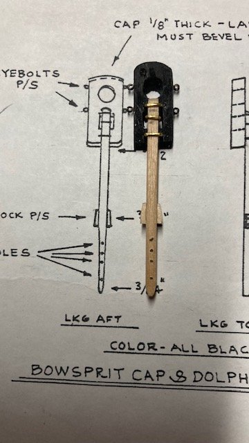
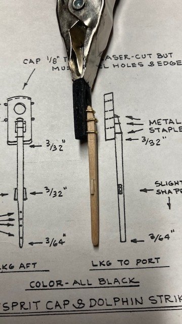
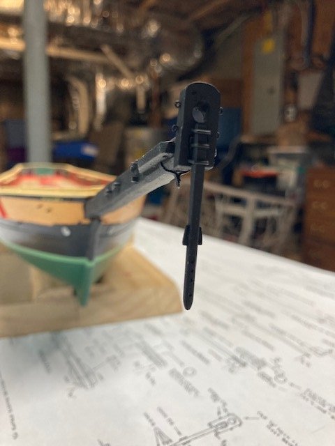
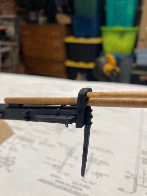
Just a brief progress update. Updated the To Do List. Before starting on the carronade carriages, I decided to make the dolphin striker - didn't want to leave this hanging (no pun intended). This was fairly easy following the detail on Sheet 4. It’s made from 3/32 square wood strip. I drilled the holes before shaping the striker. The metal staples were made from 26 gauge wire. Now, on to the carronade carriages. Stay tuned.
-
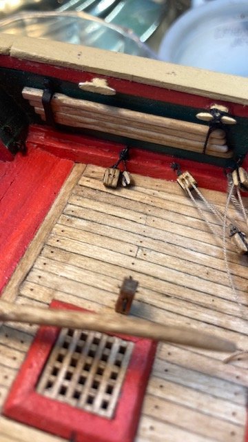
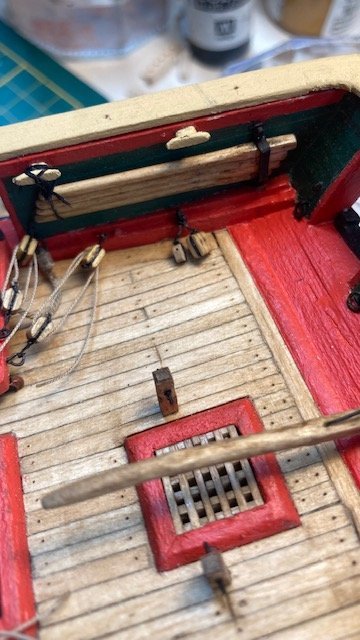
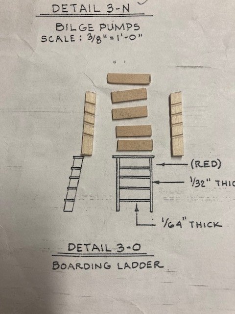
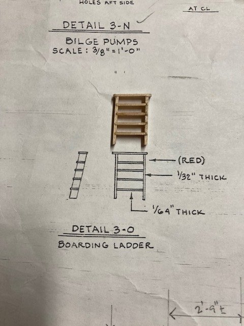
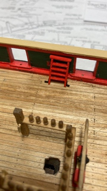
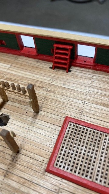
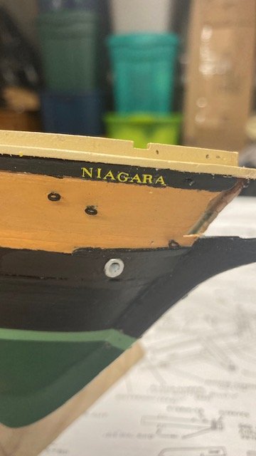
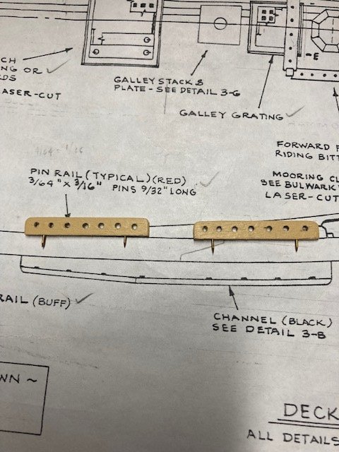
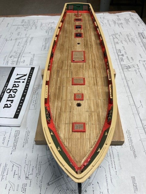
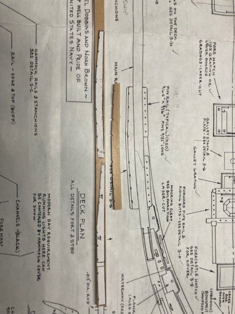
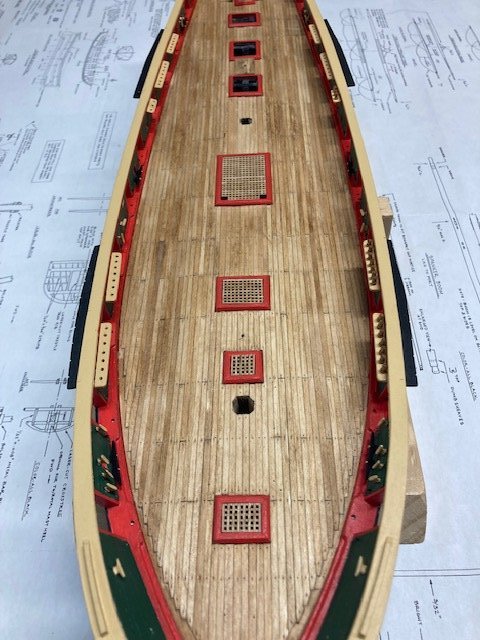
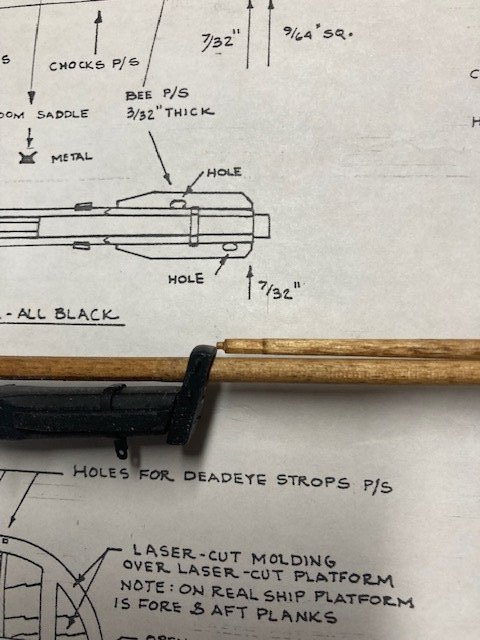
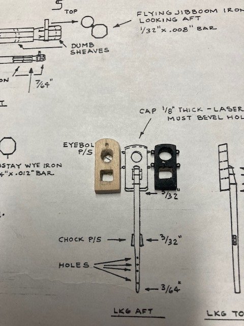
Checked off a few items on the To Do List. Finished the ship ladders, they’re not perfect but probably won’t be that noticeable. Installed the mooring cleats. Secured them with brass pins. Filed down the pin heads using my Dremel. Cut the pins down to size and filed the cut ends. Aligned the cleats with the sweep ports and drilled holes in the ceiling for the pins. Added “NIAGARA” on port and starboard sides of the bow. The lettering is not perfect, but, again, won’t be that noticeable. Decided to add the previously fashioned pin rails. I have found that there is very little discussion in other build logs on the pin rail tension rods. Some build logs eliminated them altogether. I’m inclined to do likewise, as they seem to be a pain in the *** to install. Attached the pin rails temporarily in case I need to remove them. I used the pins that I cut off the pins heads I used to attach the mooring cleats. After reading some other build logs regarding the fragility of the riding bits I decided to reinforce them by adding brass pins (see photos). All the deck furniture is complete and will be stowed away while other work is being done on the deck. Completed the channels. According to Detail 3-B, the channels are 3/16” wide fore and taper to 3/32” aft. I used 3/32” x 3/16” strips. The channel thickness tapers from 5/64” at the hull to 3/64” at the keeper. Fashioned the channels by gluing a cut out of the fore and aft channels to the wood strip and then cutting, filing, sanding the strip to match the cut out. Filed the slots for the iron strops for the deadeyes. Hopefully, they’re deep enough and wide enough for the deadeye strops. Drilled holes in the channels for insertion of pins to secure the channels to the hull, primed and painted the channels black, and pinned them to the hull temporarily. Note: The aft channels need to be notched to receive the quarter boat davit. Fashioned the jib boom and flying jib boom. The flying jib boom is attached to the bowsprit cap by a square tenon. I assembled the bowsprit, jib boom, and flying jib boom to check the fit. I didn’t like the way the flying jib boom tenon fit the bowsprit cap, so I decide to fabricate a longer cap from the laser cut board (see comparison photo). Note, the mortise in the center of the cap is not correct. I realized the flying jib boom is offset to the left, so the cap mortise was modified accordingly. Made the flying boom iron from 1/32” brass strip. I formed the strip into a figure eight and soldiered the ends together – I must say that my soldering skills are improving. For me, the hardest part of soldering is holding the piece you’re soldering in-place while you solder it. I taped the boom iron to my vise. This freed my hands to solder - it worked out well in this case. Test fit the iron - looks good. I’ve added some photos of the assembly temporarily fit to the bow. I need to update the To Do List. Thinking about working on the carronade carriages next.
.jpg.1b629eb587d4aca61a785bae0ca51369.jpg)
.jpg.2694609cc88ac7c7106a9250caed2b37.jpg)
.jpg.6f3fbe0c936c78600934fae57ab2c2e7.jpg)
-
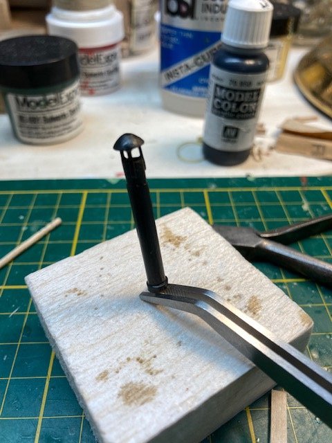
Fashioned the galley stack from the lead casting furnished with the kit. Filed the cap to make it more conic and then sawed it off the stack. Reamed the top of the cut off stack with a series of increasingly larger drill bits. This detail will probably not be noticeable, but I decided to do it anyway. Drilled a hole in the bottom of the stack and inserted a wooden pin (toothpick) for securing the stack to the deck. Cut three short lengths of 1/32” brass strip and attached them to the stack with CA. Made the stack flange from 1/16” brass strip. With the stack up-side-down, attached it to the cap with CA. Made the wood pad from 1/16” x 1/8” wood strips - I assume, in the 18 century that the pad was probably not a single piece of wood. Decided to stain the pad instead of painting it red. Painted the stack black. Drilled a hole in the pad for pinning the stack to the deck. Prior to drilling, applied CA to the pad to preclude the wood from splitting. Fit the galley stack to the deck temporarily. Now, it's on to the ship ladders. Stay tuned.
-
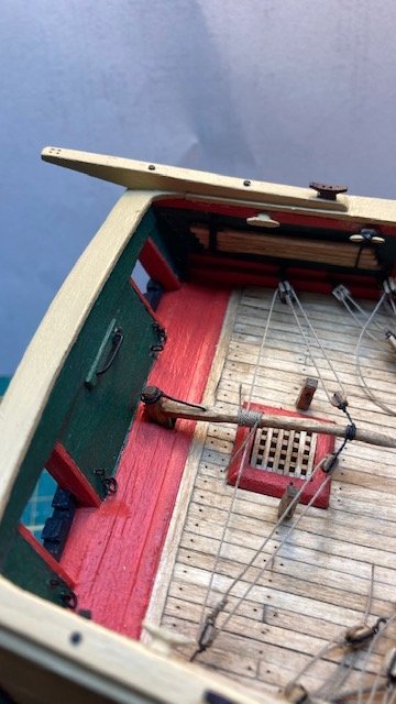
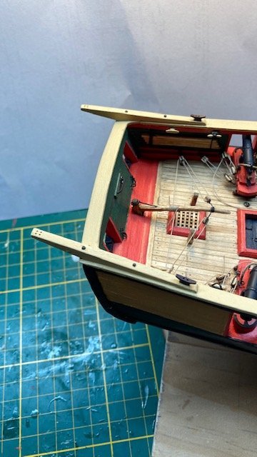
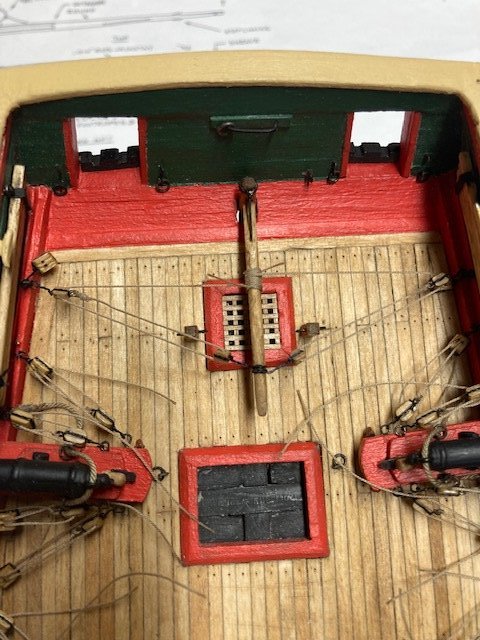
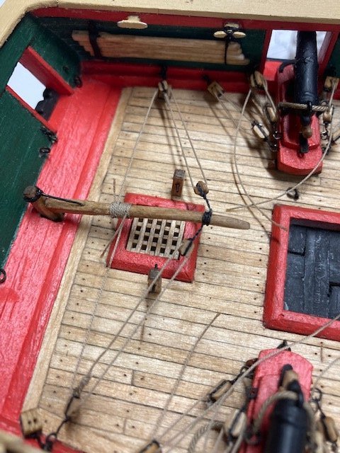
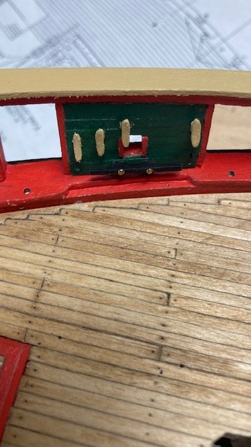
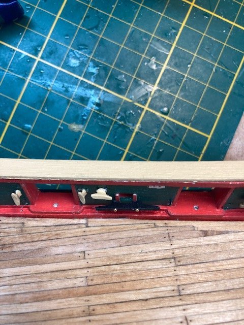
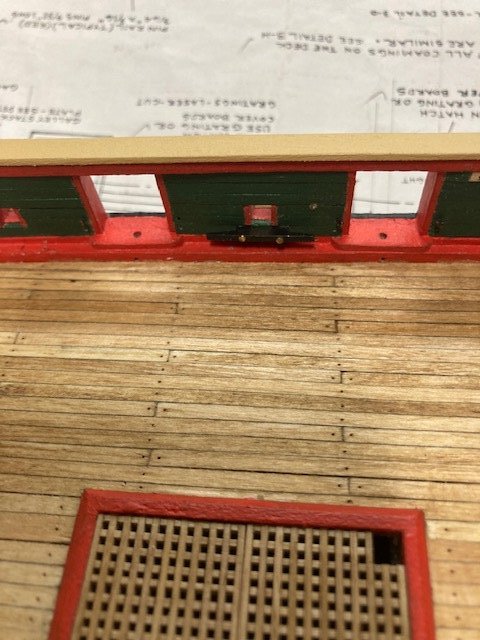
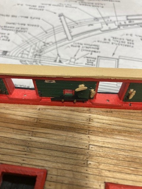
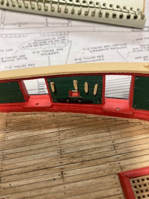
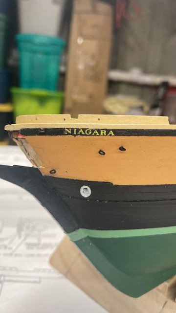
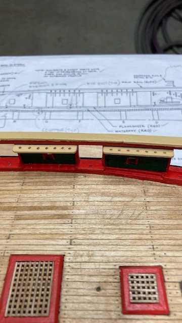
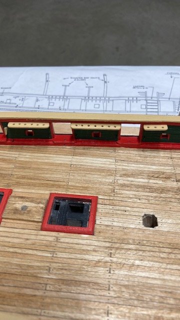
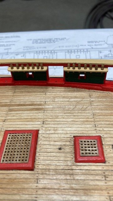
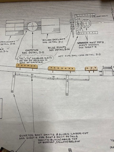
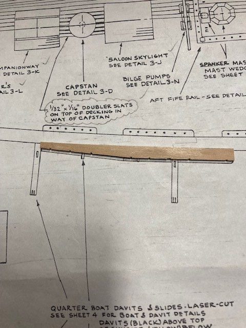
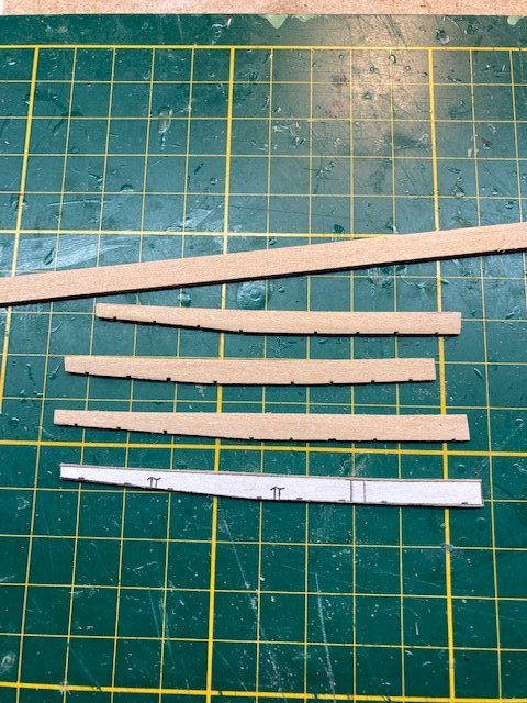
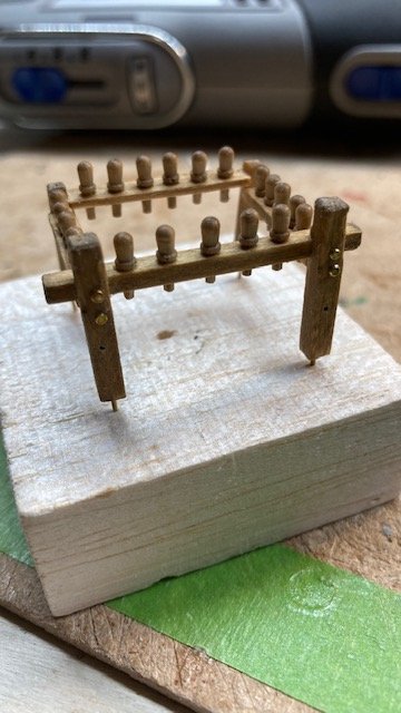
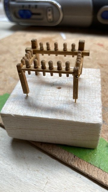
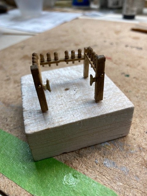
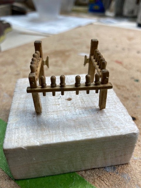
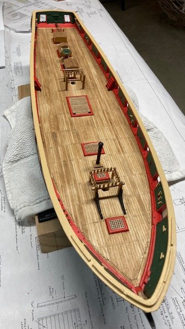
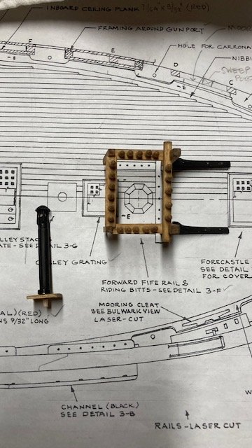
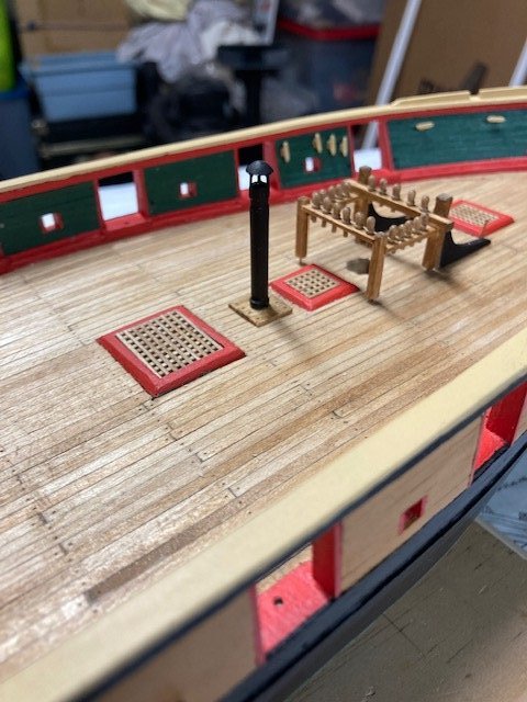
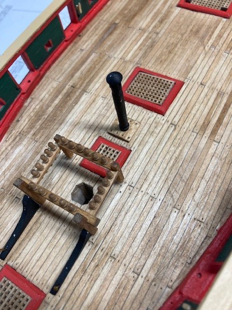
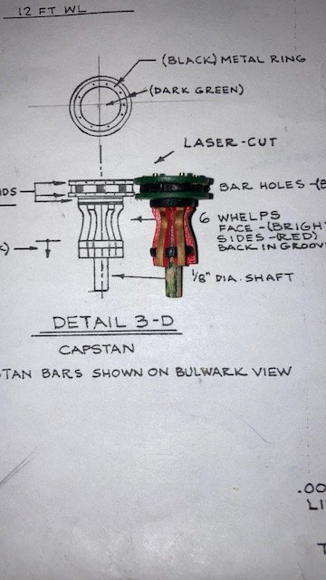
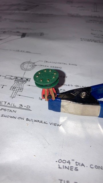
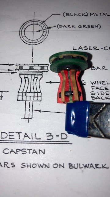
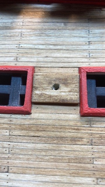
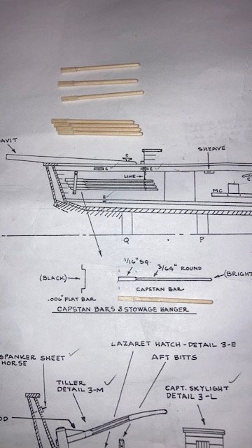
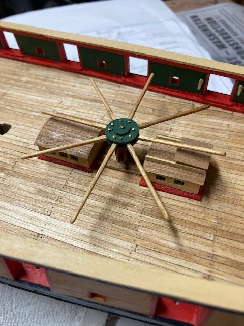
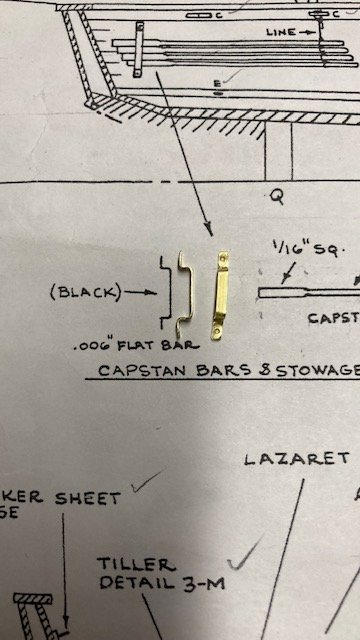
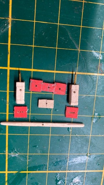
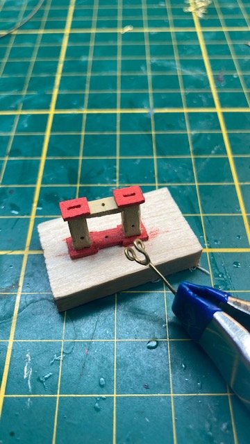
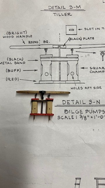
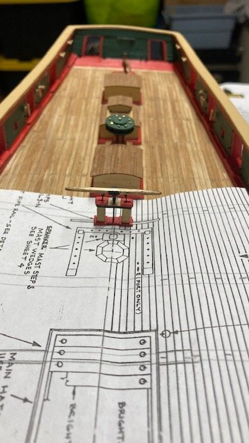
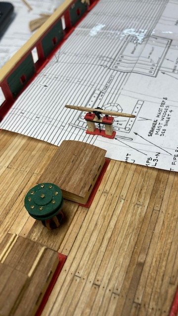
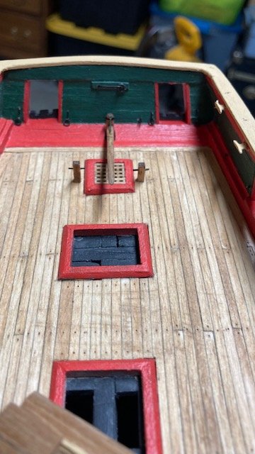
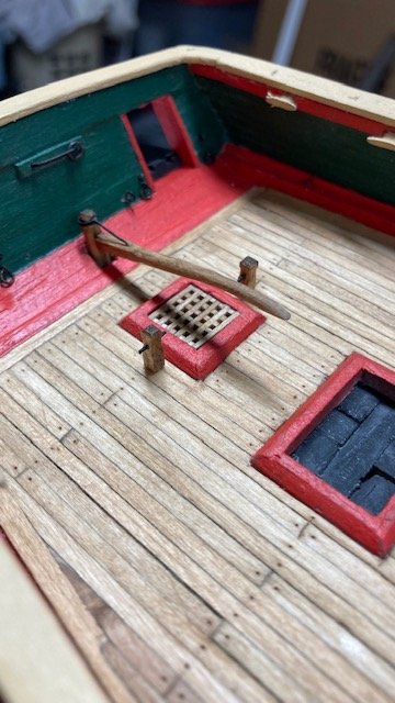
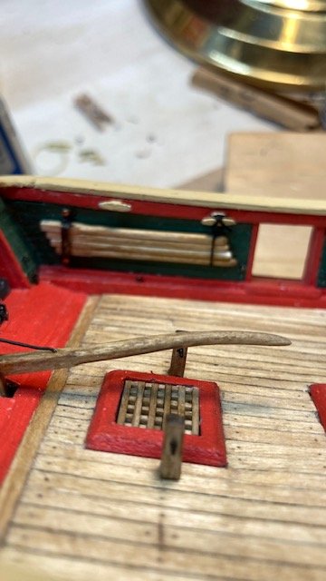
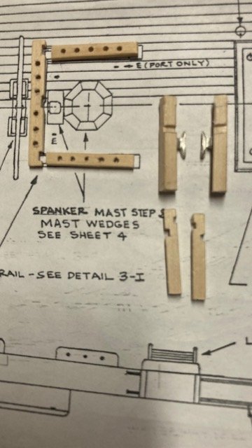
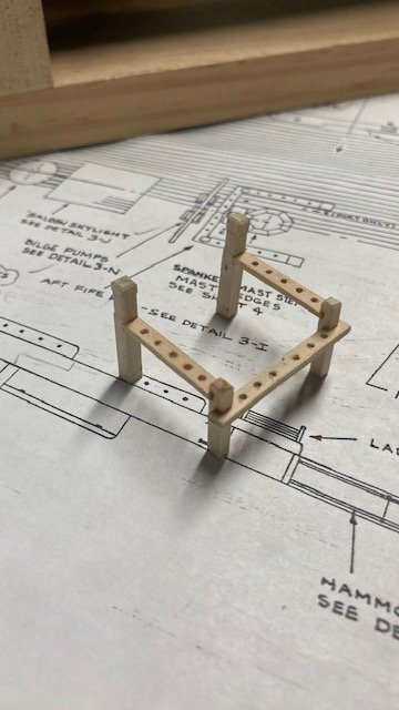
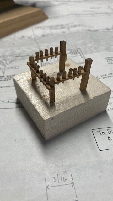
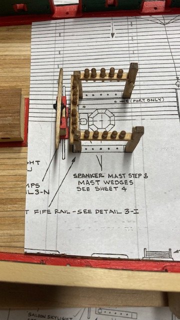
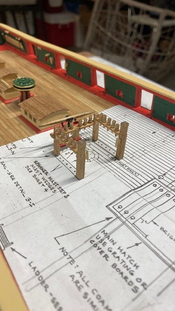
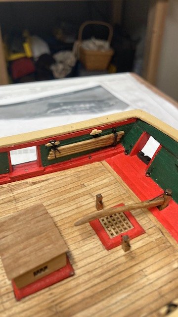
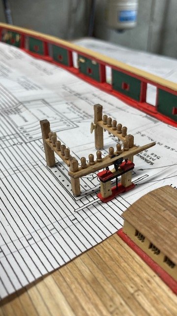
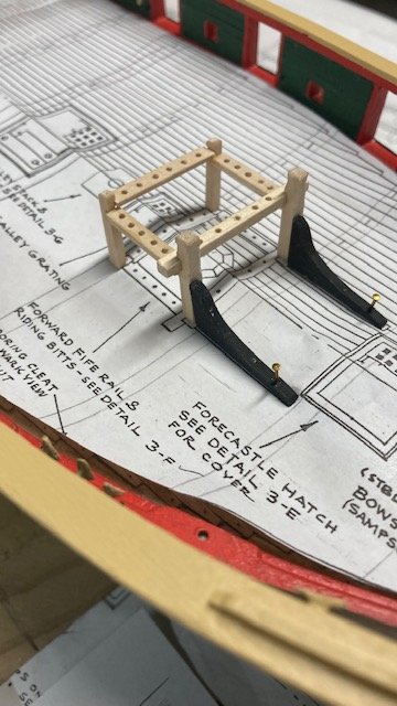
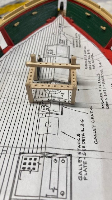
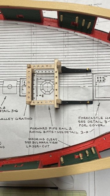
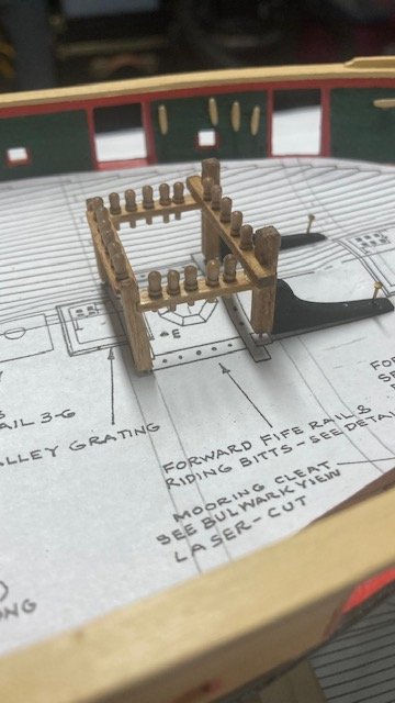
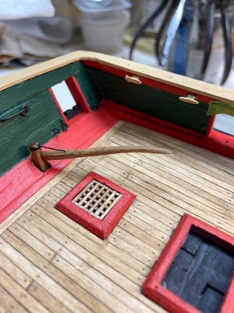
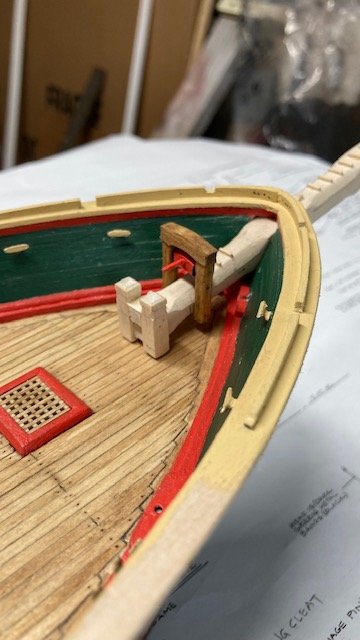
Completed the capstan. I removed the whelps and sanded off the char on the face. I realized that I should have painted the sides red before removing them from the laser board. I put them back into the laser board and painted them after-the-fact. I painted the other members as per Detail 3-D on Sheet 3 before assembling them. I can’t help it, but I think of how the Niagara colors remind me of Christmas. I applied Golden Oak stain to the face of the whelps after assembly. I added the two metal rings around the top of the capstan a using 1/16” brass strip. I opted not to add the metal ring on the top of the capstan. I did, however, add another piece to the top and brass pins as well. I filed down the heads of the pins with a Dremel and a flat file. I cut out a copy of the capstan top and used it as a template to mark the pins. Fashioned the six (6) 1/32”x1/16” doubler slats on top of deck beneath capstan. They slats appear to have a space between them, but I glued them edge to edge. There would have been no reason for caulking between them. Not sure how they were attached to the deck but I added tree nails. Stained them Golden Oak. Note: the doubler slats are called out on the Deck Plan and shown, but not called out, in Detail 3-D. Next on the To Do List, I fashioned the capstan bars from 1/16” square stock. Rounded them by hand with sandpaper, sanding sticks, and flat file - eyeballed the roundness. They actually fit the capstan (see photo). Not sure how the capstan bars worked with the companion way and salon skylight in the way. Stained the bars Golden Oak. Made the stowage brackets from 1/16” brass strip blackened with Brass Black. Drilled holes in the ends for attachment to the ceiling with brass pins. Filed the pin heads down to smaller size. I used black thread (.012”) to secure the bars to the cleat. Next on the list, the bilge pump. I made the bitts from 1/8” square stock. Marked the location of the chamfers with pencil and made the chamfers with a flat file. I drilled a hole in the bottom of the bitts for a brass nail to secure the bilge pump to the deck. Created the base, from 1/16” x 3/16” wood strip as one piece, painted it red, and drilled holes for the brass pins and the center rod. The caps on the bitts were made from the same stock as the base, painted red. For the slot, I marked it with pencil, drilled a hole at each end, and cut out the slot with a knife. For the handle, I used a wood toothpick, squared up the center section and tapered the ends. I drilled a hole in the center of the handle for inserting a pin to attach the center rod. The center block was cut from 3/32” x 3/16” stock. The “U” shaped bracket for the center rod was fabricated from copper wire. I made an eye on each end, flattened both ends, bent it with my round nose pliers. For the rod, I used a piece of .55 annealed steel wire. I glued the bracket and the rod together with CA. I find CA to be easier than solder, although it’s not as secure as solder. For the metal band around the bilge pump I used a 1/16” brass strip furnished with the kit. I formed it around the top of the pump, cut it to length, blackened it, put it back on the pump and applied CA to the cut ends to secure it. I used the same size brass rod for the small plates on the pump handle, drilled a hole in each one, blackened them, and glued them to the handle. I drilled holes in the underside of the pump handle and inserted two of the small brass eye bolts (attached to each other) in each hole. The bottom eyebolt was trimmed and simply insert in the slot on top the bitts when the pump handle was installed. The U-bracket was attached to the pump handle with a brass pin. Placed a cut out of the deck plan on the deck to establish the location of bilge pump - it’s so frail that I’m almost afraid to handle it. , 72 Made the Aft Bitts next. These where easy to make. The Aft Fife Rail was next. I followed Detail 3-I on Sheet 3. Drilled holes in the bars for the 5/16” walnut belaying pins furnished with the kit. Note: I didn't realize it when I was checking the parts list before beginning the build, but Part # MS0410 is actually 5/16” brass pins. The kit supplied walnut pins are MS0392BW. I don’t like the scale of the walnut pins and, in hindsight, wish that I had used 5/16” brass pins. I drilled a hole in the bottom of each bitt and inserted a brass pin to secure the fife rail to the deck. A la the bilge pump, I a cut out of the deck plan was used to establish the location of the fife rail on the deck. Note: It seems odd to me that the bilge pump would be as close as it is to the aft fife rail. The Forward Fife Rail & Riding Bitts are similar to the Aft Fife Rail. I followed Detail 3-G on Sheet 3. The detail is a little confusing in terms of the orientation of the side bars and the cross bars. The Deck Plan and View Along the Centerline offer some clarity. Note: the 3/32” riding bitt knees are laser cut pieces furnished with the kit. This isn’t noted in Detail 3-G. I didn’t remember this from when I reviewed the laser cut pieces noted on Sheet 1. Consequently, I made them from 3/32” laser board. Oh well, it was a good exercise. I drilled a few holes in the knees for brass pins to secure the knees to the riding bitts and the deck. The knees are painted black as per the detail. Diverting from the deck furniture, I decided to add the ship name to the transom. I used dry transfer decals (MG705 Roman) purchased from Woodland Scenics. I got the idea for the dry decals from cdrusn89’s build log. I cut out the Stern View just at the bottom of the letters NIAGARA and taped it to the transom. I positioned the decal sheet on the transom such that each letter was aligned just above the corresponding letter on the cut out and rubbed over the decal with a dull pencil. I’m satisfied with how it came out. I applied a little polyurethyane to protect the letters. Next up, the galley stack.
.jpg.8bc436459357095afeca9edae6d3841b.jpg)
.jpg.9f5a2269030283d68e35f8e2cd690592.jpg)
.jpg.973bc39e994f21c12584eab46fba14dc.jpg)
.jpg.9e9b38e3e023e09cef4ef0952128e049.jpg)
-
Thanks for the compliment, Tom. Yeah, I like the contrast of the rudder. I debated whether to paint it, but I'm glad I didn't. I just visited your build log and looked at your capstan. I just completed mine, but I like the way you put the bands around the top of the capstan. I might give that a try.
-
Just started following your build log, Your ship is looking finely detailed, and I see you've been at it for quite some time - slow and steady wins the race, as they say. My Syren build took me 2 years to complete. I'm definitely going to follow your log more closely as I move along on Niagara. Keep up the fine work. BTW, I noticed the Bruins cup on your work bench. They're having an unexpected, great season.
-
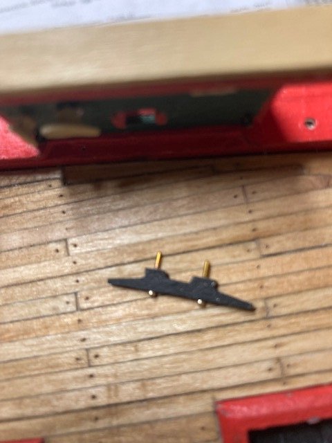
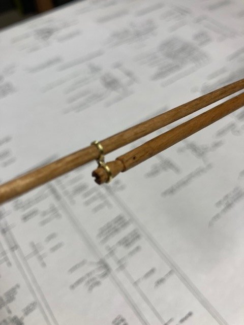
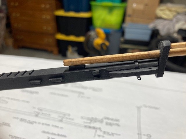
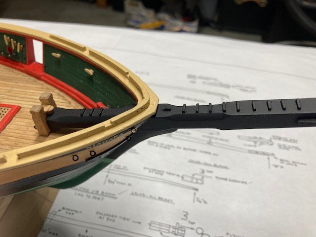
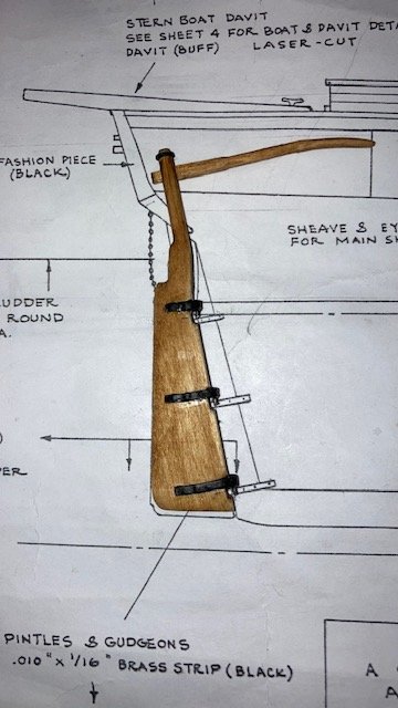
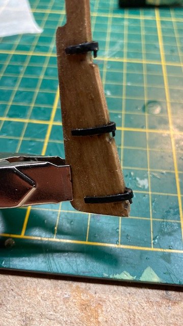
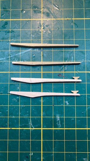
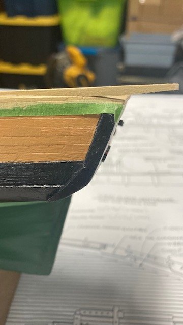
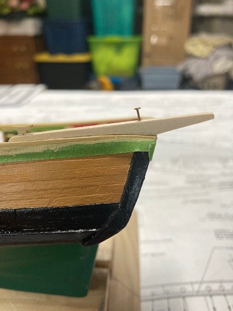
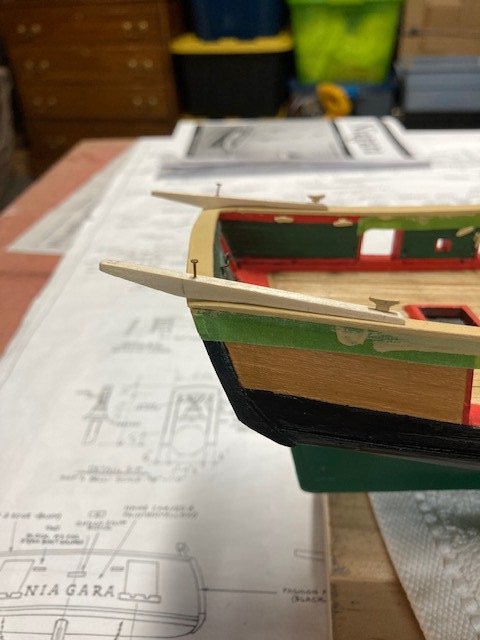
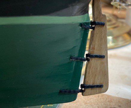
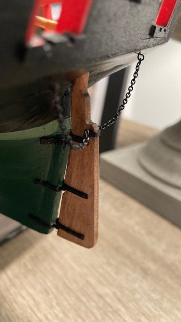
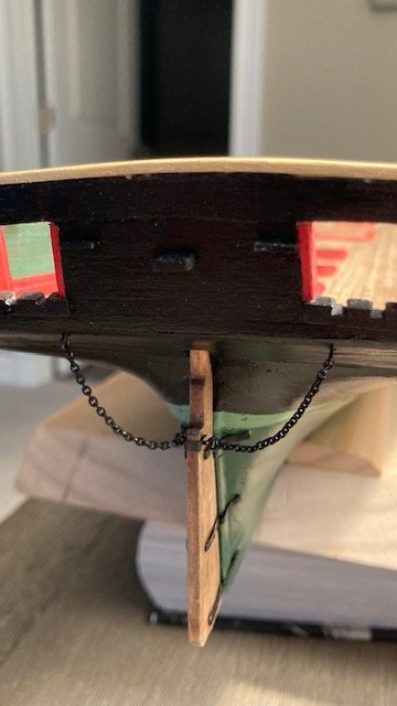
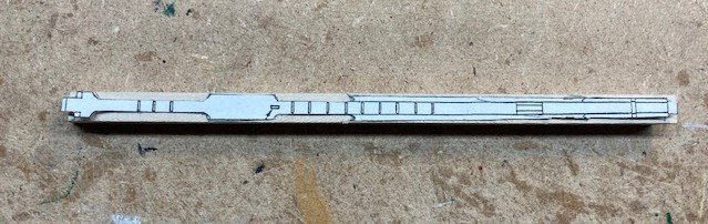
Finishing up the hull, I gave it one coat of satin polyurethane. Moving on to the rudder, I removed it from the laser cut board, sanded off the char, tapered it, and rounded it above the rudder stock, as shown in the Outboard Profile on Sheet 3. The rudder has a black band at its top. I formed a piece of 1/16” brass strip around the rudder top, trimmed it, and applied CA to seal the cut ends. I drilled a hole in it for the .012” rod that attaches to the tiller. I used 28 gauge wire for the rod. The band was painted black. Next, I removed the tiller from the laser cut board. I thought the tiller was too thin to be shaped as shown on Sheet 3, so I made one from scrap laser board (see comparison photo). I filed/sanded the tiller to create the octagonal section and rounded section, and then cut the tenon. I used an x-acto knife to cut the mortise in the rudder - a little difficult, but I managed to create the mortise without damaging the rudder. The rudder and tiller were stained Golden Oak. The detail in tiller isn’t that noticeable. Started fabricating the rudder pintles and gudgeons. I used 1/16” brass strips. To simulate nail heads, I marked the location of the nail heads on the brass strips and punched them with an awl, which left an impression that looks somewhat like a nail head. (Unfortunately, I forgot to take photos before painting them black). I bent the strips over a 1/8” dowel. For the pintle pins, I tried my hand at soldering with no success. So, I secured the pins to the pintles with CA – much easier. I secured the pintles to the rudder with CA. The gudgeons were somewhat difficult to install on the stern post/hull. I installed the lower gudgeon first. Next, I set the middle and upper gudgeons in the pintle pins on the rudder, set the lower pintle pin into the lower gudgeon, and pressed everything in place. I aligned the middle and upper gudgeons and secured them to the stern post/ hull with CA. The rudder fit is not as close to the stern post as I would like - it’s functional but not removable. I attached the tiller to the rudder and installed the .012” rod. The rod was a little tricky. Note: There are two 3/32" single blocks that are attached to the tiller for the tiller tackle (Detail 5-L on Sheet 5). I didn't realize this until after I secured the tiller. The blocks will be installed later - I'm sure it would have been easier to have added them before the tiller was secured. Fashioned the bracket for the rudder chains from 1/16” brass strip, and drilled holes for the chain eye bolts. I made the eye bolts using the .020” copper wire furnished with the kit. The copper chain links furnished with the kit don’t fit the small eye bolts furnished with the kit. The chain (MS0526) has 42 links/inch. For comparison, I looked at the parts list from my Syren build, which is the same scale, and the chain links (MS0435) are larger (27 links/inch). Rather than order the larger link chain, I used some sterling silver chain with 27 links/inch that belonged to my late wife. I cut the chain to the appropriate lengths shown in the Stern View on Sheet 3. Sterling silver will not blacken with Brass Black, so I spray painted it black. I’m satisfied how it came out. Next up the davits. I couldn’t use the laser cut davits because the port and starboard main rails are bent at the stern - my miscue. In hindsight, should have built up the transom to avoid this. The laser cut davits don’t sit flush on the main rail (see photo). I made some davits from scrap laser board. With a lot of sanding and filing, I got the davits to fit fairly flush with the main rail (see photos). They're unorthodox, but I don't think they'll be noticeable to the untrained eye. I pinned the davits temporarily to test the fit. I created the faux sheaves at the end of the davit. For the davit cleat, I used a Syren 7mm boxwood cleat. I will permanently install the davits later in the build. My past experience with installing the davits too early is that they are prone to being accidentally snapped off. I think I’ll make the deck furniture next, starting with the capstan. Stay tuned.
.jpg.adcd19c98a6b9e9f63fea0085c1b5d11.jpg)
.jpg.486eae6e8550f1880b46636b37858d54.jpg)
.jpg.285c655fd43a9162dd61a5db59f6279d.jpg)
-
Thanks for your input. I addressed the issue of eyebolts earlier in this build log. I brought it to the attention of Model Shipways and they promptly sent me another package of 120 small eye bolts - they're good like that.. I have bashed kits and Model Shipways for numerous discrepancies that I have discovered between the plans, instructions, and parts list.
-
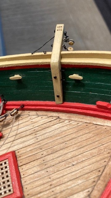
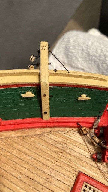
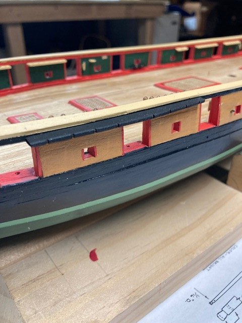
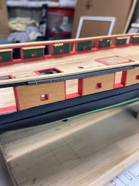
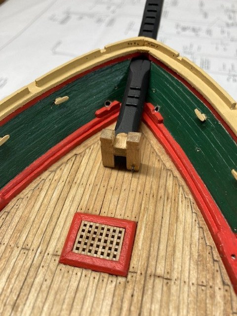
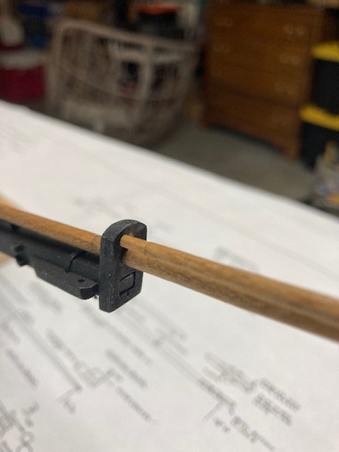
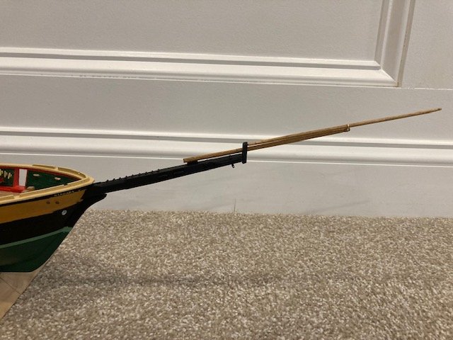
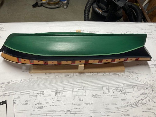
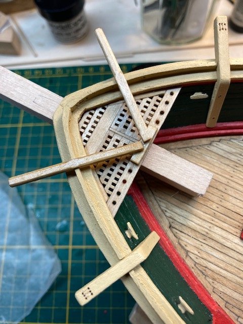
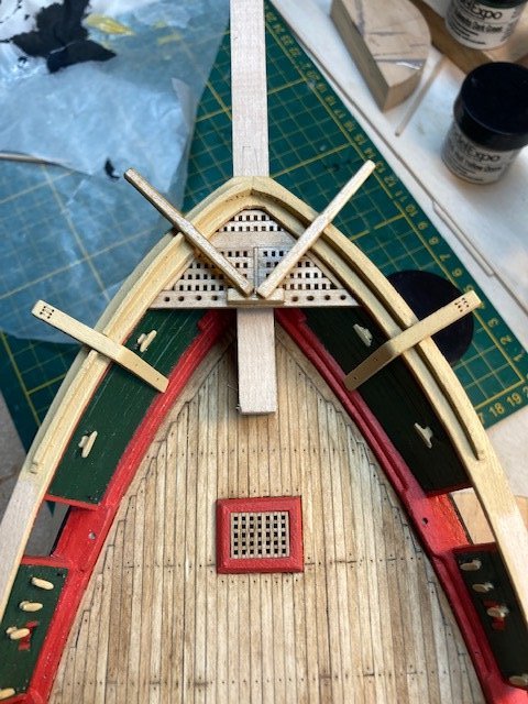
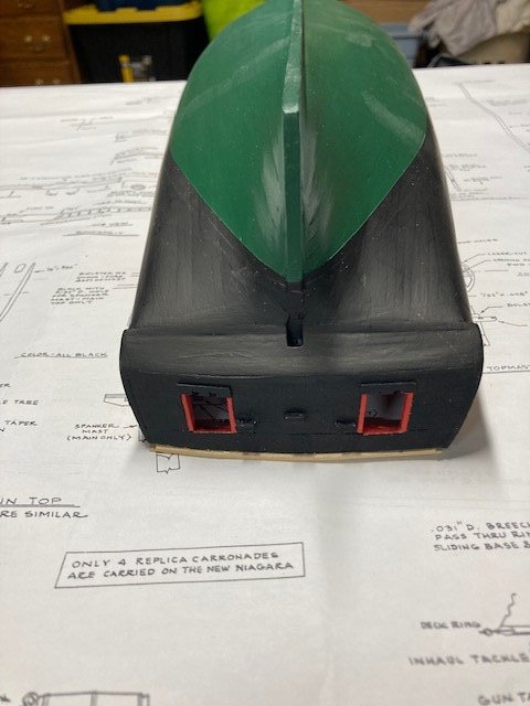
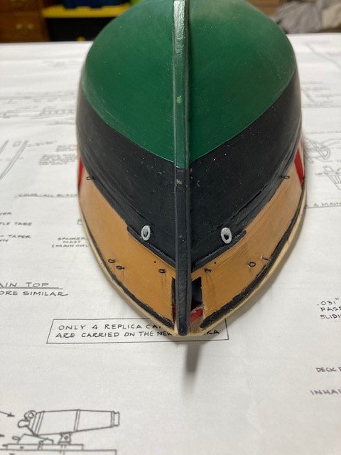
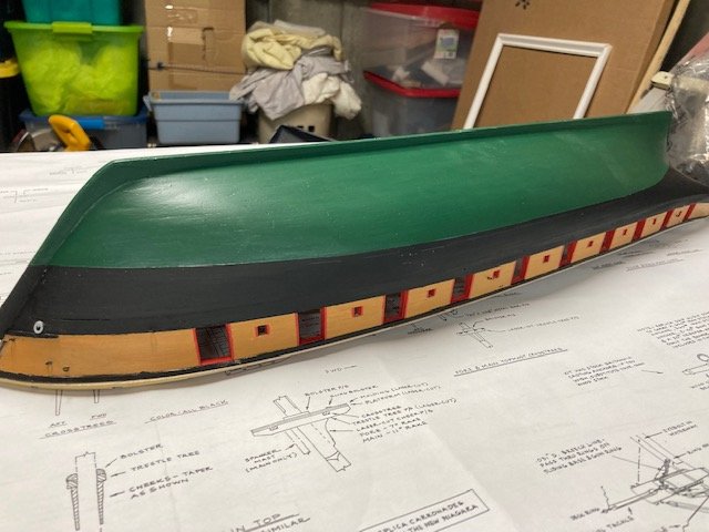
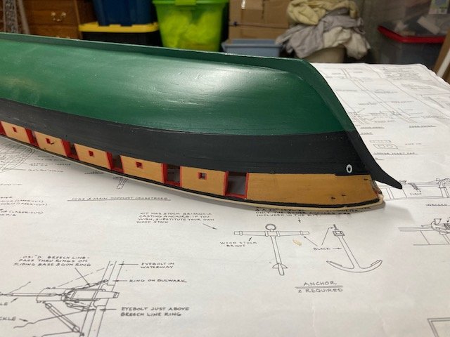
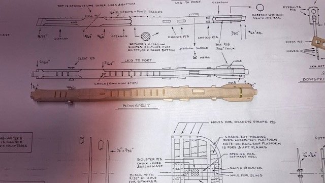
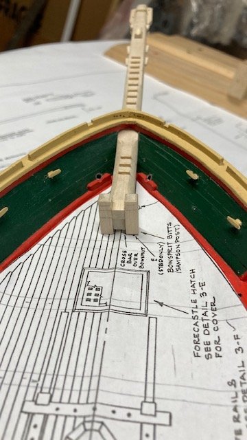
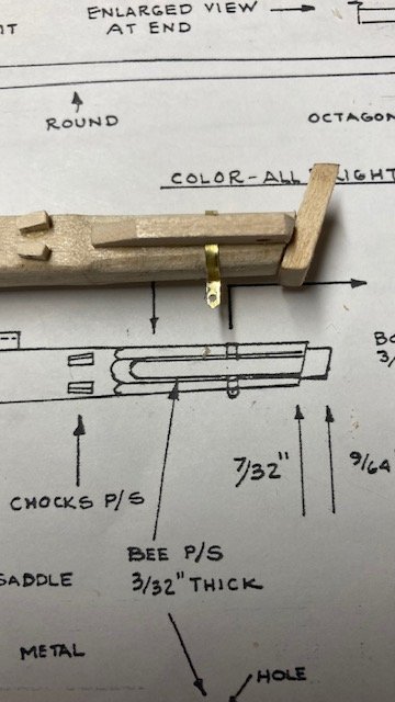
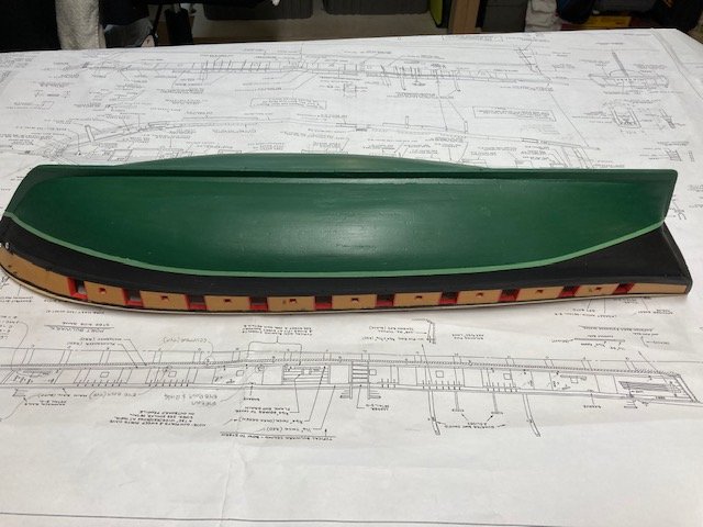
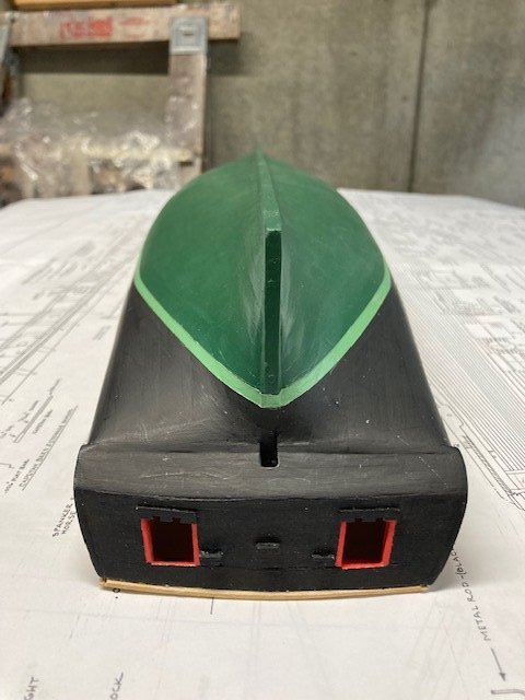
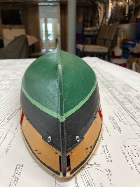
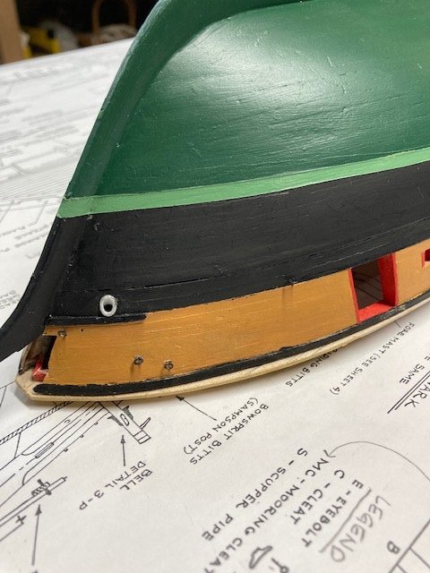
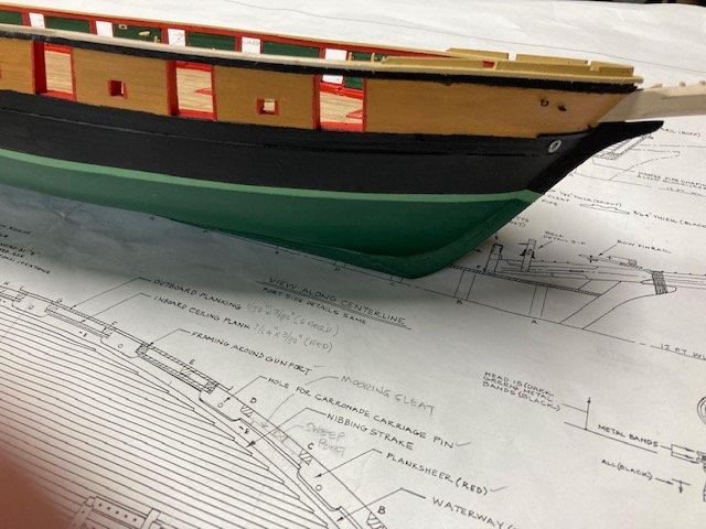
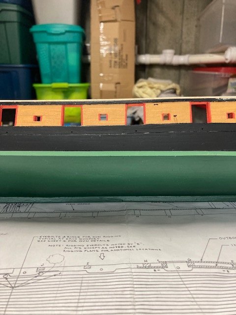
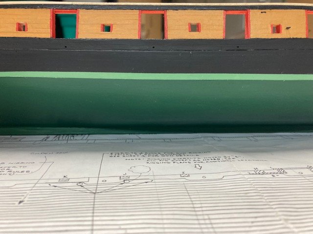
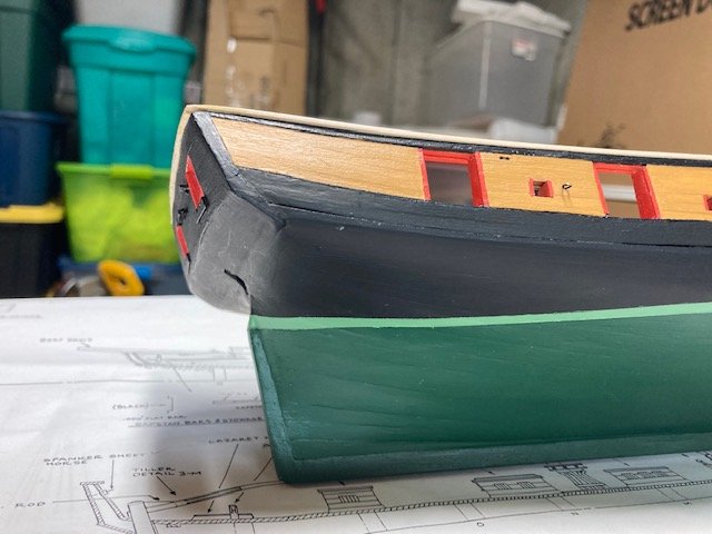
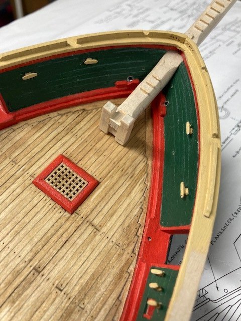
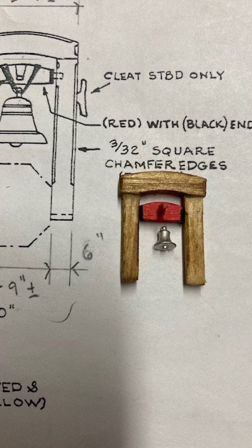
Hope everyone had a merry Christmas. This will be the last post for 2022. Work is progressing on the Niagara. At this point I’m 6 months into the build – not in any hurry. I’m loving the build the more I advance and the more challenging it becomes. I added a piece of grating to the bow at the boomkin structure. I drilled holes in the end of the boomkin for eyebolts to which chains will be attached (see photos). In To mark the water line, I used a marker that I made from a speed square and Acco clips (see photo from Syren build). I used Frog Tape to mask the hull at the pencil line in preparation for painting. I painted (by brush) the hull above the waterline to the plank sheer first. I used Model Color black acrylic paint. Before applying paint, I sanded the area and wiped it clean with a tack cloth. When dry, I lighted sanded the paint, wiped it clean again, and applied a second coat. With that done, I masked the hull in preparation for painting below the waterline. I lightly sanded the hull and wiped it clean. I applied (by brush) the first of three coats of Bulwarks Dark Green paint (ModelExpo MS4801). I sanded between each subsequent coat. Most of the hull won’t be visible whence the ship is mounted on its base. I’m pleased with how it turned out. With that done, I moved on to fashioning the bowsprit. I cut out a copy of the top and side views of the bowsprit bow from the plan and used it to mark the locations of the tenons, octagonal sections, chocks, cleats, foot treads, bees, etc. I used the 3/8” x 3/8” basswood strip furnished with the kit. I tapered the bottom and sides of the bowsprit with a flat file and sanding block, cut out the octagonal sections with an x-acto knife and then filed/sanded them to shape. Added the foot treads (1/32” sq. strips), chocks, cleats (temporarily), bees (1/8” x 3/32” strip), and bob stay wye (1/64” x 1/16” brass strip). I wrapped the brass strip around the bowsprit, formed it to the octagonal shape, removed it from the bowsprit and solder the ends together. I drilled a hole in the end for the metal strop for the bobstay. The cleats will have to be added after the bowsprit is permanently installed. I fabricated the bowsprit saddle from a piece of 1/8” thick laser board. Note: the plans call for this to be fabricated from metal. I didn’t see the need for that since most of it will be covered by lashing and the detail will be obscured when painted black. I beveled the holes on the bowsprit cap and inserted the small eye bolts as per the detail on Sheet 4. While I was on the bowsprit, I decided to make the bowsprit bitts (Detail 5-B on Sheet). I used 1/8” sq. strip. I chamfered the top edges. I laid a cut out of the deck plan onto the deck to establish the location of the bowsprit bitts. I added brass pins in the bottom of the bitts. The pin holes will allow for the bitts to be placed in the exact location when it comes time to permanently install the bow sprit. I rough fit the bowsprit and the bitts to check the alignment. I had to adjust the angle of the notch at the end of the bowsprit to achieve the proper fit. Next, I fabricated the ships bell. Just a note, the ships bell is attached to the bowsprit as shown in the View Along the Centerline on Sheet 3. Detail 3-P on Sheet 3 shows a dashed line of an octagon which represents the bowsprit in section. This wasn’t obvious to me until I reviewed the View Along the Centerline. I cut the pieces out of 1/8” thick laser board. I used Detail 3-P on Sheet 3 as a guide. I drilled through the uprights and the piece that the bell is attached to so that I could install it later and insert pins to secure it. The kit supplied Britannia cast bell looks too small. It scales 12” in diameter at 3/16” scale. At 3/8” scale in Detail 3-P, it scales about 18”. I’ll have asked ModelExpo to substitute a Corel C-76 brass bell 8mm x 6mm diameter bell. In the meantime, I stained the frame Golden Oak and painted the piece that holds the bell Model Expo MS4802 Bulwarks Gun Carriage Red. Note: Before I fabricated the boomkin grating structure, I checked the plans to see if it might interfere with the ships bell and it doesn't (see photo). With that task done, I turned my attention to the boot topping. I used a 1/8” wide wood strip to mark the boot topping above the waterline. I carefully applied frog tape (this stuff is great) along the waterline and the boot topping line. I cut narrow strips of tape to facilitate bending the tape along the lines. The plans call for the boot topping to be light green. On a whim, I mixed Bulwarks Dark Green paint with Deck Light Buff to achieve the desired shade of light green -Voilà. I applied two coats by brush. I allowed the paint to dry completely before carefully removing the masking tape. I had to touch up a few minor spots, but otherwise it came out well. Eventually, I’ll apply a coat of polyurethane to the entire hull to seal and protect it. I think I’ll move on to the rudder next. Happy New Year!
.jpg.9cef263af3b3fe8ec660291af372af0a.jpg)
.jpg.5475adfd468a5fc5598b99df3c1f2e3a.jpg)
.jpg.1cacf8232d0231eaed20046e3e4311c8.jpg)
.jpg.a04692258a3ecbbd1da49fe8569c2b8e.jpg)
.jpg.6ff0d100ae1647ecd642f081eed4e712.jpg)
.jpg.76a6fce2e3985724ea29ff01c4ca2482.jpg)
.jpg.093ad383102c9cb1e1d74a09d09c554e.jpg)
.jpg.83191f3e17653e53a419598572b8536e.jpg)
.JPG.a248bcd52224dd3b8ba65cb28fff0735.JPG)
.jpg.b23c689dbf82c876aba335c5d25cddbb.jpg)
.jpg.5d8f7341b24d85c6486d79ecaa0b59fe.jpg)
-
Thanks for the compliment, it boost my ego.
-
Didn't realize that you moved to Japan. Hope everything is going well and that you'll soon be back to the Syren.
-
Your work is consistently so neat and clean. A level of perfection that's hard to achieve. Don't know how you do it.👍
-
Thanks, that's the aim.


