

abelson
-
Posts
467 -
Joined
-
Last visited
Content Type
Profiles
Forums
Gallery
Events
Everything posted by abelson
-
 A nice keepsake. Bruins are off to a good start. Your ship is really taking shape. Nice work.
 -
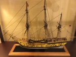
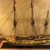
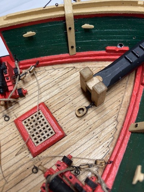
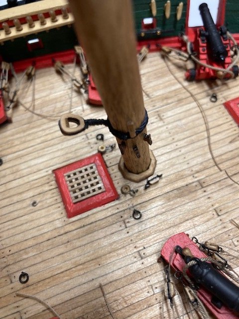
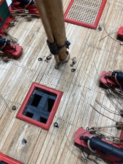
Completed the rope coils-phew. I must say that I prefer the look of the deck sans rope coils. The deck looks cluttered now. Next up, deck furniture. x
.jpg.3e2726ea3b4e1319e561b6a0ab6ce509.jpg)
.jpg.1cc0a5b654c655e0863eea6b866b2376.jpg)
.jpg.9caf3083d599160e244936bf739d08fb.jpg)
.jpg.ce94424338cfb17610e4d690b54acbf6.jpg)
.jpg.2fd99bb7c2f80762e6503db5c4704179.jpg)
-
Looking good Tom. I recovered from Covid two weeks ago. It really zaps your energy.
-
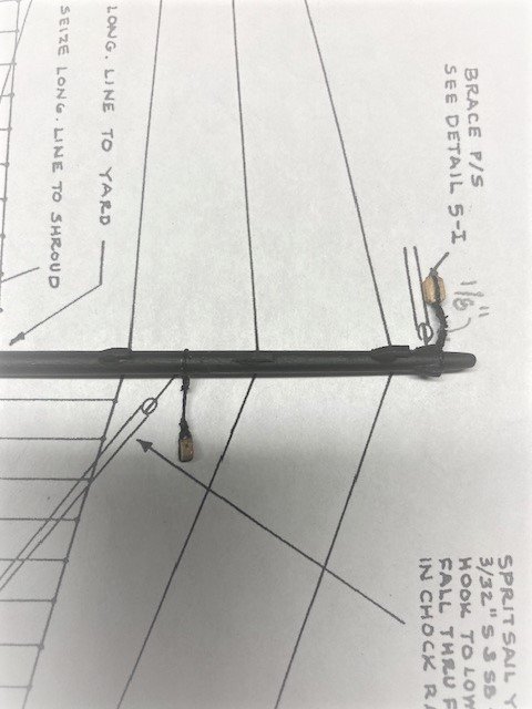
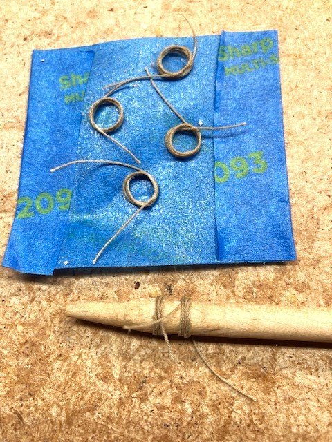
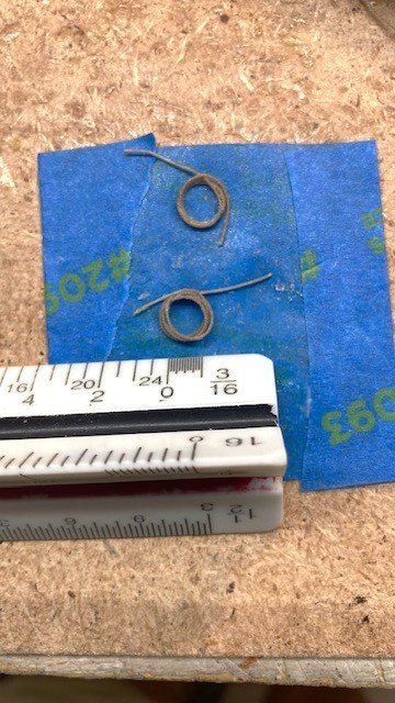
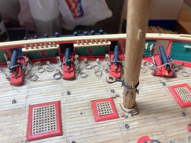
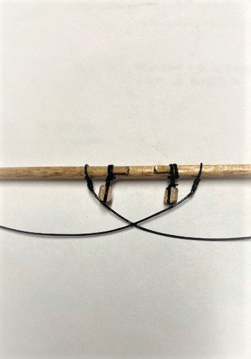
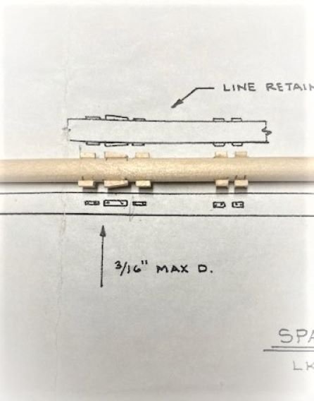
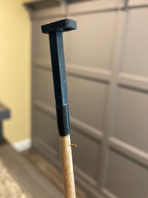
Completed the sprit sail yard. Added the 3/32” single blocks for the lifts and the 1/8” single blocks for the braces. Moved on to the monotonous task of making the 76 rope coils for the carronades. I revisited my Syren build log to refresh my memory of how I previously made the rope coils. Many build logs neatly coil the rope. I figure the sailors on a war ship probably didn’t neatly coil the rope and, if they did, the rope probably didn’t stay coiled for long. So, I decided to un-neatly coil the rope. I wrapped .012” tan Syren rope around a 3/16” dowel (see photo) 4 times, applied a little CA to the loose ends, and then brushed on a 50/50 solution of white glue and water. When dry, I gently slid the rope off the dowel and unto some masking tape, flattened it out somewhat, and applied a little more 50/50 solution of glue and water. For me, this technique is easier than neatly coiling the rope. Added some coils to the deck for effect – looks good (see photo). More to come.
.jpg.2bf50be96c75fdca47c9bc96849b5254.jpg)
.jpg.ac616913c67edf9829a7558fc3b4f836.jpg)
-
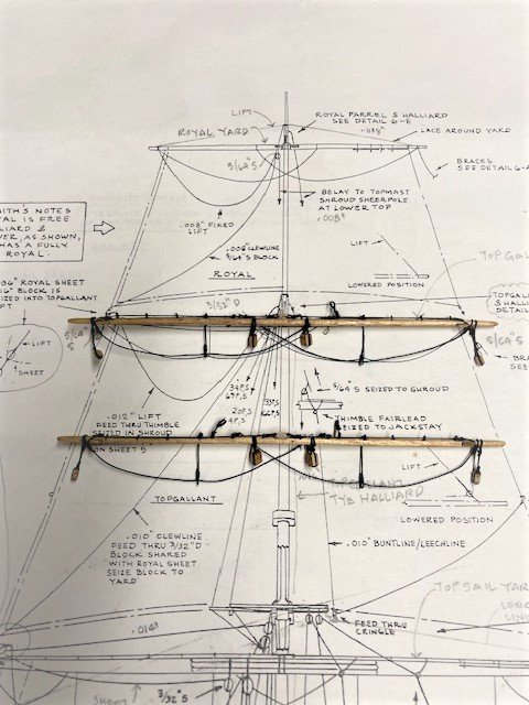
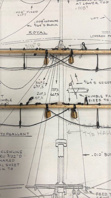
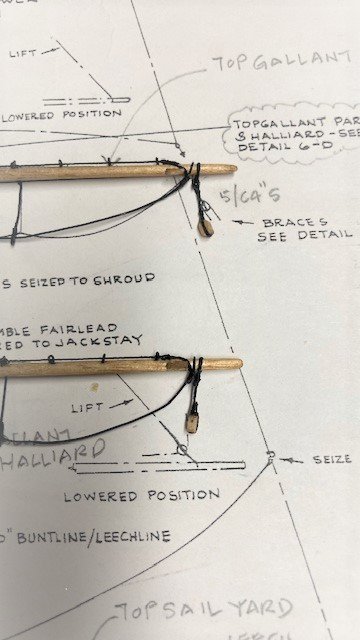
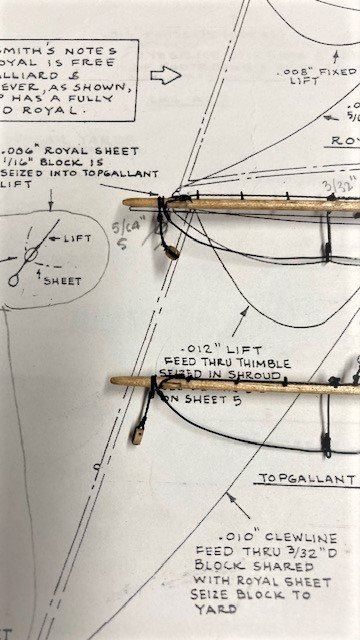
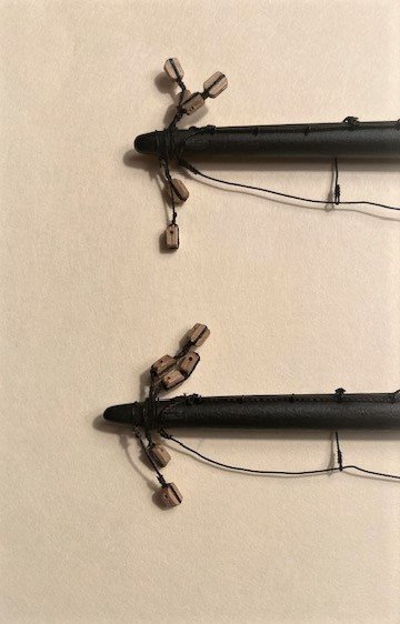
Moving on to the Top Gallant Yards, Sheet 6 calls for 3/32” double blocks for the Top Gallant Sheets and Clew Lines. The kit is not furnished with that size block, so I used the next size up 1/8” double. It also calls for 5/64” single blocks for the Top Gallant Braces, which also are not furnished with the kit. I used 3/32” blocks instead. Furthermore, 1/16” single clump blocks are called out for the Royal Sheets, also not furnished. I will use 3/32” blocks instead. Note: The clump block is seized into the Top Gallant Lift, so when you add this block to the Top Gallant Yard you’ll have to use a long enough rope to belay the lifts to the pin rail on deck. These will be added later. Added the jackstay eyebolts, rope (.012”), eye splices, and lanyard (.012” tan rope). I made the eye splices first, reeved the rope through the eyes, and seized the rope to the mast. I completed the Top Gallant Yards by adding the blocks for the Royal Sheets, Top Gallant Sheets and Clew Lines, and Braces, and the stirrups and foot ropes (20 gauge annealed wire). The topgallant yards have a thimble fairlead seized to the jackstay as detailed on plan Sheet 6 Main Mast, Looking Aft (see photo). The Royal Yards are next. I added 3/32” single blocks for the clew lines (plans call for 5/64” blocks, which are not furnished), and foot ropes (20 gauge annealed wire), Except for the Course Yard braces and the yard tackle for lifting cargo, The yards are complete. I debated whether to add the yard tackle, as many build logs eliminated this. I decided to add them - I presumed there is one on each course yard. I made them basically as shown on sheet 6. I Seized a pendent to the Jack stay to hook the tackle to. It’s not clear to me how this tackle works. The location of the rope suggests that the cargo was hauled up from the course yard. I coiled a length of Syren .012 tan rope and belayed it to the Jack stay rather than hang on slings. I realized later that if the tackle was lowered to lift cargo from a boat, the rope would have be about 140 feet long. Be that as it may, I definitely didn’t coil enough line. I completed the course yards by adding the braces. At this stage, all of the yards are now complete. Next up, add the blocks for sprit sail yard. Stay tuned,
.jpg.fcaafa393e7a390aa1edc953693ad89d.jpg)
.jpg.2a6ca739405ce1c5c65fe00db9a5e36c.jpg)
-
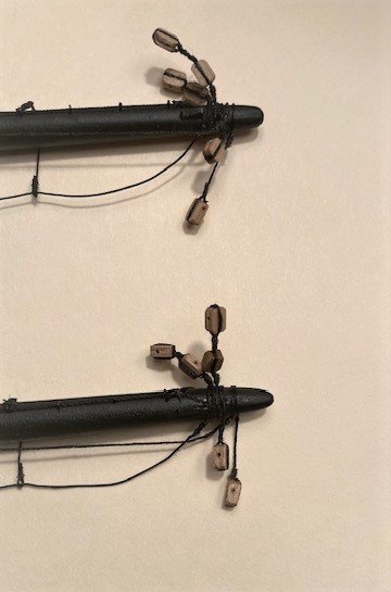
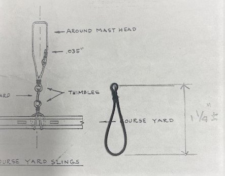
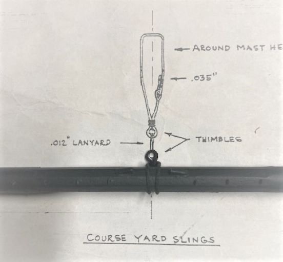
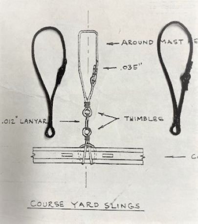
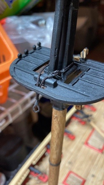
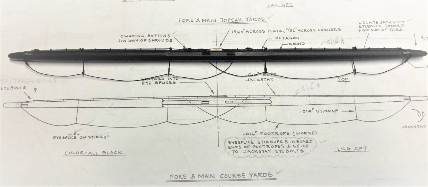
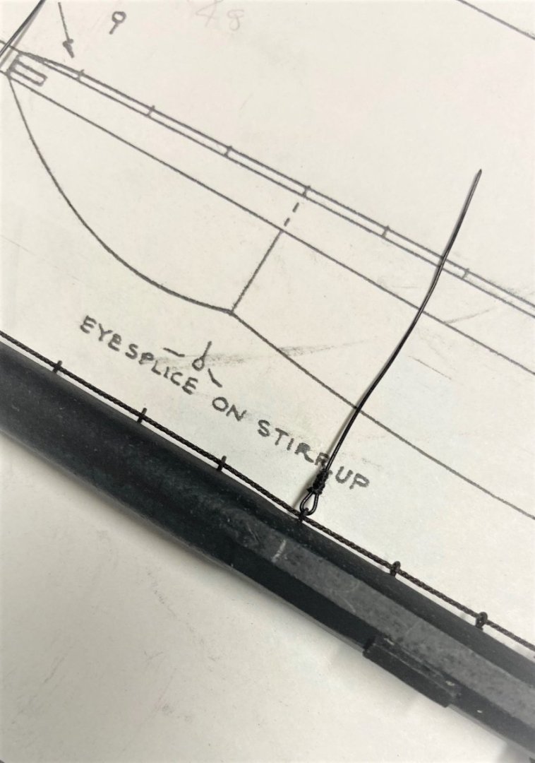
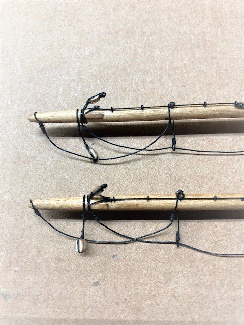
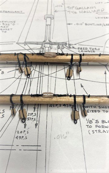
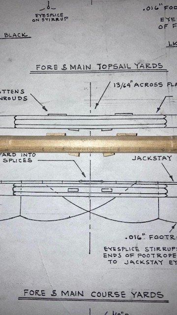
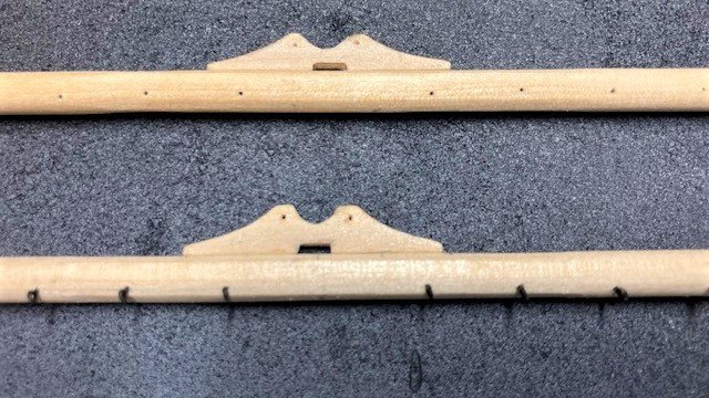
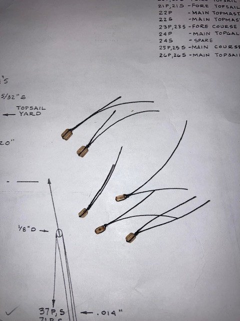
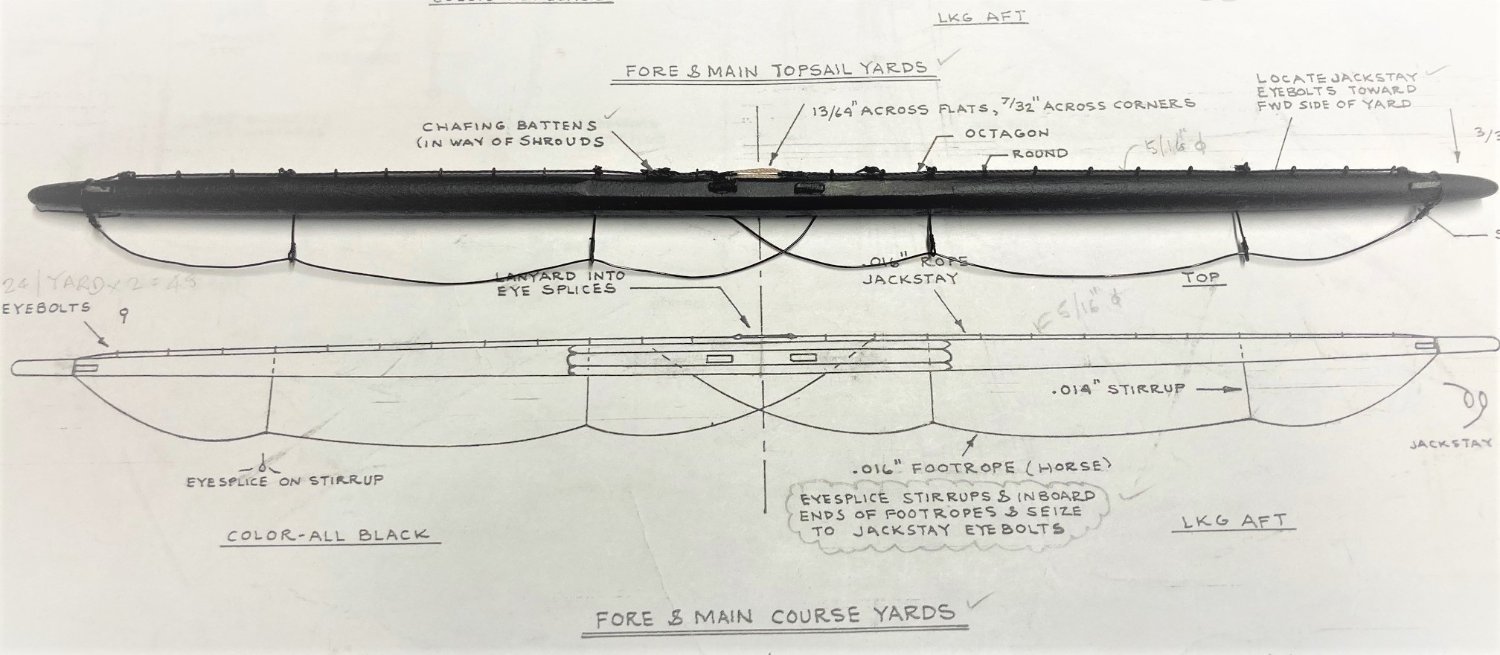
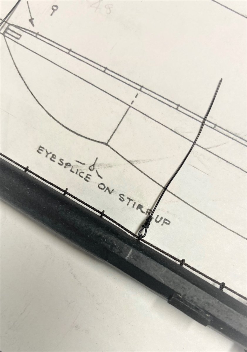
Made significant progress on the Fore and Main Course Yards and the Top Sail Yards. Added the jackstay eyebolts, rope (.018” line for the Course Yards and .012" for the Top Sail Yards), eye splices, and lanyard (.012” tan rope). I made the eye splices first, reeved the rope through the eyes, and seized the rope to the mast. The hard part is getting the space between the eye splices to get the proper lanyard length. Fashioned the Course Yard Slings. I used Syren .035” rope. It’s difficult to get the right lengths. After a couple of failed attempts I think I got it right. I made the yard slings about 1 1/4” long and the mast slings about 1 7/8” long. Next, the stirrups and foot ropes. A la my Syren and Fair American builds, I used 20 gauge annealed wire for the stirrups and the foot ropes. They were eye spliced to the jackstay eyebolts and seized with black sewing thread. To the Fore and Main Course Yards, I added the 5/32” clump blocks for the Topsail Clew line and the Course Yard Lifts and Sheets, the 5/32” single blocks for the Reef Tackle, the 1/8” single blocks for the Clew Garnet, and the 5/32” single blocks for Top Sail Sheets. The 5/32” single blocks and pendants for the braces will be added later. One dilemma I had was where to place the 1/8” single blocks for the Clew Garnet lines and the 5/32” single block for the Fore Topsail Sheets, because the plan sheet shows them in the same location as the chafing battens on the aft side of the yards, meaning that the blocks would be wrapped around the chafing block. So, I decided to move them so that the don’t interfere with chafing blocks. Added the fairleads with short pendent for the bunt lines and leech lines. Finished the Fore and Main Top Sail Yards. Added the 3/32” single blocks for the Topgallant Sheets, 5/32” single blocks for the Top Sail Clew lines and the 1/8” single blocks for the Braces, the thimble fair leads, the stirrups, foot ropes, and Flemish Horses. Note: The Flemish Horses are shown on the plan but are not called out. Clarification: The 3/32" single blocks for the Topgallant Sheets are supposed to be seized into the Top Sail Lift as detailed at the Royal Yard on Sheet 6. I missed this detail and made a lash in the block for seizing the Top Sail Lift as can be seen in the left and right photos below- my bad. Next on the To-Do-List, the Top Gallant Yards and the Royal Yards.
.thumb.jpg.bf08006e934d1757607596d1d4876349.jpg)
.thumb.jpg.efff2660d48e100039091445314f5b9e.jpg)
.jpg.95d11f361e3a7eace4125af067ef823a.jpg)
.jpg.c7b2d1cdf22b80ef6982c08c8af90cce.jpg)
.jpg.50a3ffd61d3a6069374fe184fb7b7043.jpg)
.jpg.cd2951d5626b6c44440dfac417d4eebd.jpg)
.jpg.ccfcccf62a8efda7275c3dc2643c8b08.jpg)
.jpg.b5633ec83edfbb48a84dbb4811fadbf1.jpg)
-
Thanks. I've only created the hulls, so I can't help you out there. Did that early on in the build. I'm thinking that will be one of the last things I'll do.
-
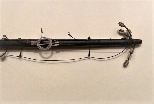
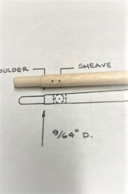
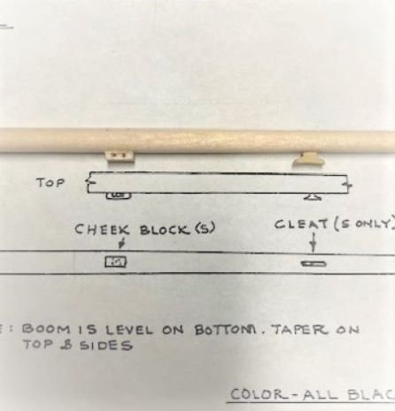
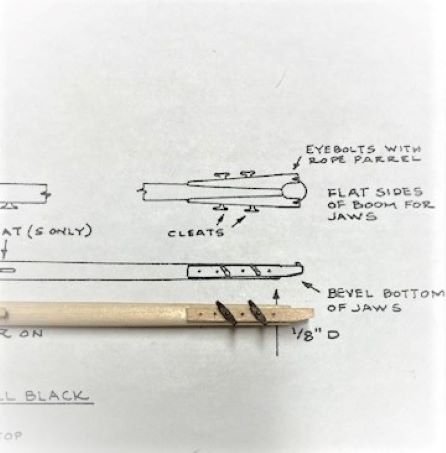
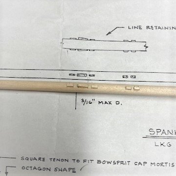
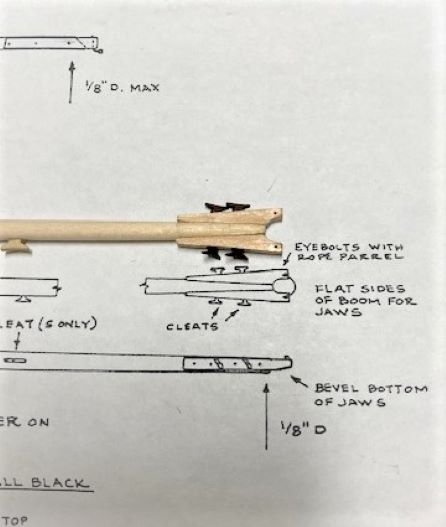
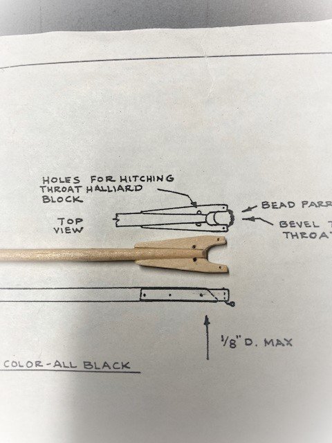
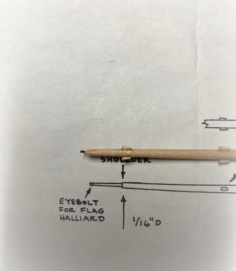
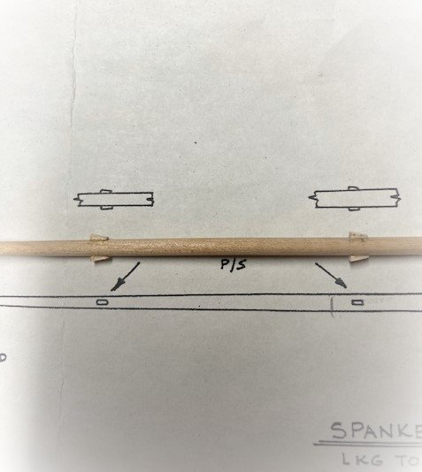
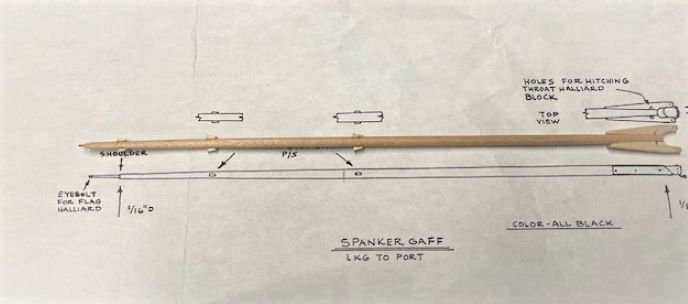
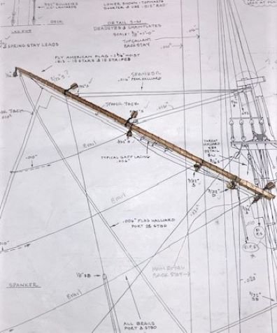
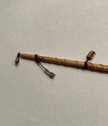
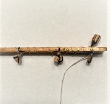
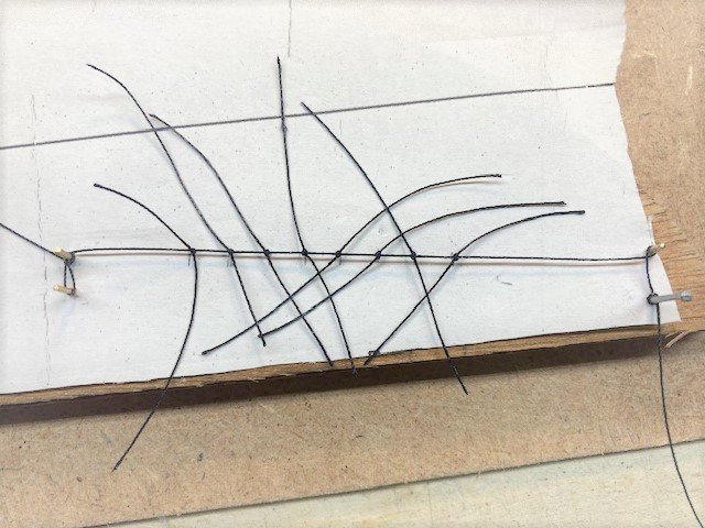
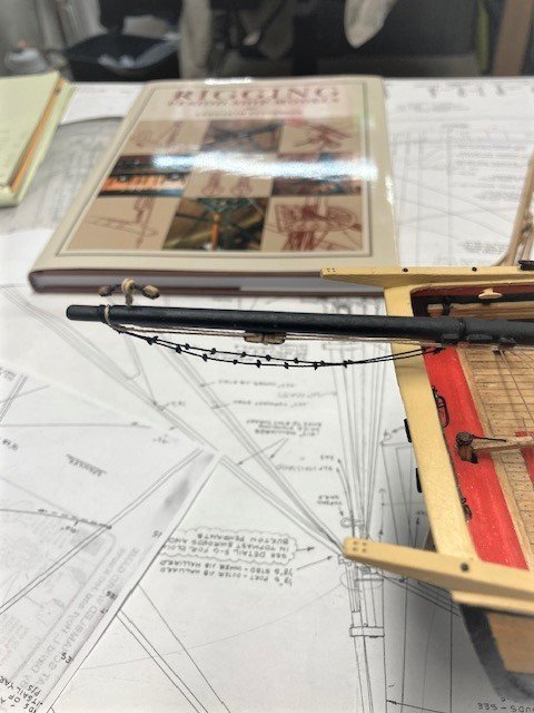
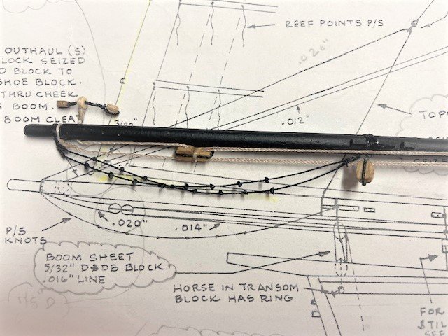
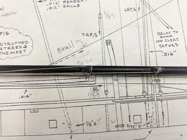
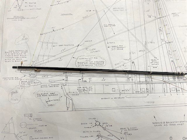
Fashioned the Spanker Boom from 3/16” dowel. I used my poor man lathe to taper the boom. Leaving about a ½” of dowel for insertion in the drill chuck, I cut and filed the aft end of the boom down to the approximate thickness (9/64”) before tapering the boom. Made the faux sheave and added the chocks (P&S), cheek block (S only), boom cleat (S only), jaws, and jaw cleats (5.5mm from Crafty Sailor). I made the jaws from 3/32”x 3/16” stock. I cut out a photocopy of the jaws and glued it lightly to the wood strip and used it as a guide for cutting and shaping the strip. Primed and painted the boom black. I left the Crafty sailor cleats in their natural color for contrast. I added brass pins to the jaws to simulate bolts. The Spanker Gaff was fashioned from 1/8” dowel. The gaff is only tapered on the aft end. Added the halliard stop chocks (P&S) and the jaws. The gaff jaws are a little thicker than the boom jaws, so I used a 1/8” x 1/8” wood strip. I cut and shaped the strip a la the Spanker Boom jaws. I drilled the holes for hitching the 5/32” double block for the throat halliard (Detail 5-J) after gluing the jaws to the gaff. The plan calls for the gaff to be painted black. On the replica ship the gaff is natural. I decided to make the gaff natural, so I stained it with Minwax Golden Oak. Also, the replica ship does not have the “shoulder” shown on Spanker Gaff detail, so I eliminated this and added chocks for the spanker tack. A la the Spanker Boom, I added brass pins to the jaws. Continuing with the Spanker Gaff, I added the three 3/32” single (P&S) and one 3/32” double (P&S) blocks for the Brails, as shown on the plans. I also seized the two 5/32” single blocks for the Peak Halliard, and the 5/32” double block for the Throat Halliard and added lacing. Note: The kit is not furnished with 3/32” double blocks, so I trimmed down a 5/32” double block. Also, the plan calls for a 1/16” single block, which is not furnished with the kit, for the flag halliard. I used a 3/32” block. The Brails run down to the deck and are belayed on the aft fife rail. I haven't seen these on any other build log. Another item that I’ve only seen on one build log is the clew outhaul shoe block. As noted on Sheet 5, this block is made up of a 5/32” single block and a 1/8” double block seized together. Note: The replica ship does not have this block. The outhaul tackle is seized to the Spanker Boom fore of the cheek block and is reeved through the double block and the cheek block, back through the double block and is then belayed to the boom cleat. I’ve studied the plan and can’t wrap my head around how the clew outhaul works with the shoe block in the position that it is shown on Sheet 5. The way I think it works, when you pull on the tackle, the sail is furled and the leech and foot lines move in two directions with the aid of the brails. The clew line travels with the leech and foot lines and ends up below the throat of the gaff as can be seen in the attached photo or midway at the Spanker Mast (sail luff) as pictured on Sheet 5. Getting back to the clew outhaul shoe block, I think the position shown on the plan would be the position of the blocks with the sail furled because when the sail is unfurled the outhaul shoe block would have to travel fore. I might be wrong here, but if anyone can better explain the workings of the Spanker Sail I’m all ears. At this point, I’m unsure how or if I will present the brail, leech, foot, and clew lines on the ship. In the meantime, I've fashioned the clew line as per the plans. Note: Landlubber Mike's technique for furled sails on Model Shipways has a good description of spanker sail component and how to make sails. For the Spanker Boom foot ropes, I stretched a length of .012” line between two brads set in a board over laid with paper. I made tick marks about 1/4” about on the paper to mark the location of the knots. I tied a knot at each location, applied a little CA to each knot, and trimmed the loose ends. Next, I seized each foot rope to the Spanker Boom. The difficult part is trying to get the ropes to lineup. I also added the two 3/32” single blocks (P&S) that pass through the cringle at the end of clew line. Each has a block and tackle midway on the Spanker Mast. I added the 3/32” single blocks at the Spanker Mast for the Brails. The blocks were seized to the mast hoops as they appear to be on Sheet 5. The out hauls (P&S) are belayed to the aft fife rail as shown on the Belaying Plan on Sheet 6. Lastly, I added the fair lead for the boom sheet and the 3/32” double block with ring attached to Horse in transom. Seize the 3/32” double block to the Spanker Boom. Now, it's time to move on to completing the yards. Moving on to some of the miscellaneous items, I added 1/8” single blocks to the main topmast cross tree for the topgallant braces (as per the replica ship) and the lift lines, and the sling (.018” tan) to the Main Mast for the gaff lift line.
.jpg.d3ac886c54e17de36b507edd46207ec7.jpg)
.jpg.9672c537a6dcbb1cd610a2e92417085e.jpg)
.jpg.6173229095cdfde7cf941350e3ea1383.jpg)
-
Good pickup on the blocks for the topgallant braces - Detail 6-A incorrectly shows them on the straight crosstree.
-
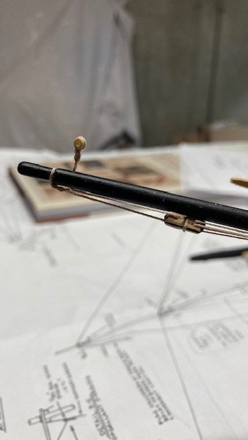
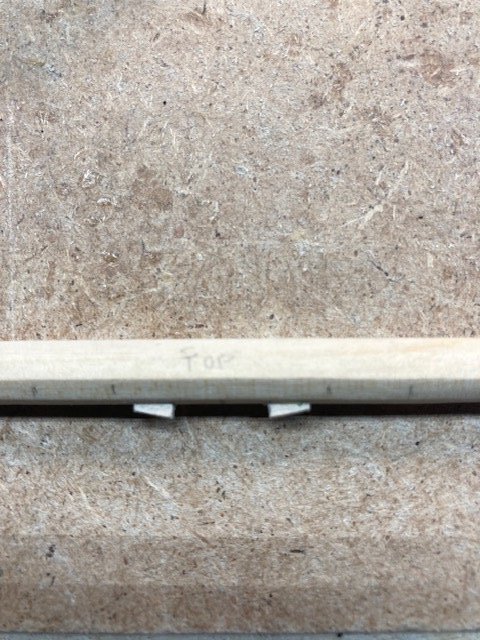
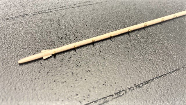
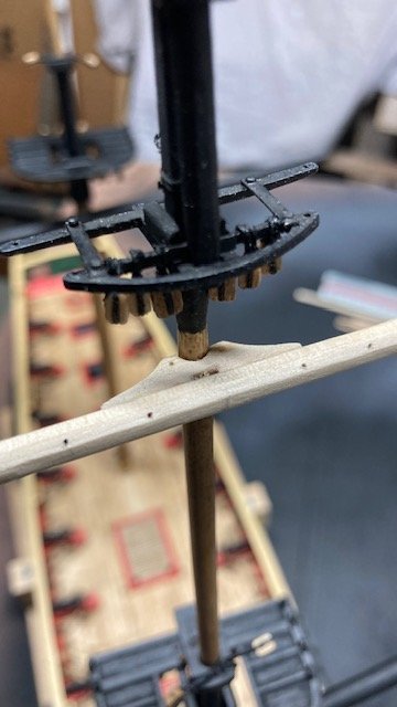
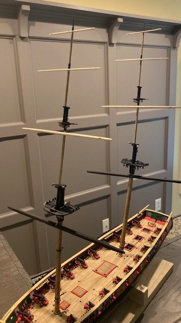
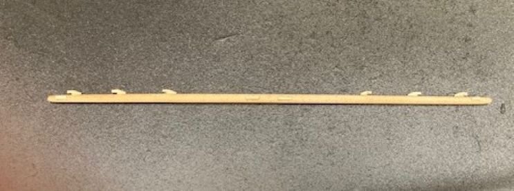
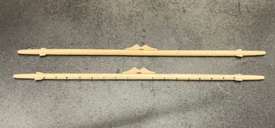
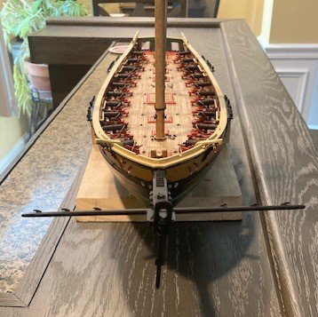
Made some significant progress on the build but, first, getting back to the Top Rope sheave, I found an explanation in Laxet’s build log by BillLib, as follows: “The top rope was used to hoist and lower the topmasts. It was hooked under the underside of the cap, reeved through the sheave at the foot of the topmast, up through a block, which was hooked to the cap, and down to the deck. On a model the top rope can be omitted, as it was only used when sending up or striking the topmast and was only rigged at those times. The only traces to be seen are two or four ringbolts on the underside of the cap.” BillLib cites Historic Ship Models, Wolfram Zu Mondfeld. Thus, I will omit the top rope in my Niagara build, but the faux sheave does make it authentic – no lost effort there. And, digressing here, after studying the plans, there seems to be a discrepancy between the plans and the replica ship. Detail 6-A notes that the blocks for the topgallant braces are seized to the straight section of the Main Crosstree. However, on the replica ship the blocks are seized to the curved section of the crosstree (see photo). Also, in the photo there’s another block adjacent to the bunt line and leech line blocks and only one block in the shroud. The lone block in the shroud I believe is for the reef tackle. I believe the additional block in line with the leech line and bunt line blocks is for the topgallant lift line. Began fashioning the Fore & Main Course Yards. To shape them, I used a poor man’s lathe (see photo), i.e., two drills with one end of the dowel secured in the drill chuck and the other end free to turn in the drill chuck. I left a ½” on each end of the dowel for insertion in the drill chuck. I started by marking the ends of the yard with a pencil. Then, I cut around the pencil mark with an x-acto knife and remove a portion of the dowel as a starting point for shaping the dowel. I used a combination of files and sanding blocks. It’s time consuming, but it works for me. The parts list calls for ¼” dowel. I like to use a little larger diameter dowel so that when the octagonal section is shaped it’s truer to scale. I used a 5/16” dowel. When shaping the dowel, I don’t use a micrometer to check the thickness, I just eyeball it and compare it to the plan. The photos make the yards appear thicker then they are, albeit, I admit that the taper is a little thicker and the plan. After shaping the course yard, I created the octagonal section. The small chocks, chafing battens, and Jackstay eyebolts were next. The stop chocks we’re cut from 3/64”x3/32” strip, glued on the yard, and shaped in-place. The chafing battens were cut from the same stock. I marked the locations of the jackstays with a pencil and straight edge and then drilled the holes for the eyebolts (6mm). Note: The eyebolts are located “toward the fwd side of the yard.” I cut the eyebolts down to size, test fit them, and blackened them. I primed and painted the course yards black. Moved on to the Fore & Main Topsail Yards next. These were fashioned basically the same as the course yards, except that I added the battens. I couldn’t find any photos of the replica ship that show the battens, but I decided to add them anyway. I figure the yards will be easier to mount with the battens – time will tell. The battens are pinned to the yards. Lastly, the Fore & Main Topgallant Yards and the Fore & Main Royal Yards. These were fairly easy to shape. I added the battens to the Topgallant Yards a la the Topsail Yards. All of the yards were pinned temporarily to the masts (see photos). The plans call for all yards to be painted black. On the replica ship, except for the course yards, all the yards have a natural (bright) finish. I’ve already painted the course yards black. I’m undecided whether to make the rest of the yards black or bright finish. Fashioned the spritsail yard as per the plans. The chocks and the cleats aren’t quite to scale but when rigged won’t be noticeable. The spritsail yard was primed, painted black, and temporarily pinned to the bowsprit. There's still some work remaining to complete the yards, i.e., Jackstay eyebolts, eye splices and a lanyards, stirrups, footropes, rigging blocks, et al, but I think I'll fashion the Spanker Boom and Spanker Gaff first. Stay tuned for updates.
.jpg.2f58def9939199c81eb2871e48125f94.jpg)
.jpg.f5689ddf83b9cb6d876f58943106548f.jpg)
.jpg.8f8bf814caf1d3a0352720192edff2d4.jpg)
.jpg.33d5efef8e68ad0147fe35e3dc5f5bbc.jpg)
.jpg.8e94a4b3791d8a2d90ef04fddf144381.jpg)
.jpg.a18d1ee8898194cd33de48b01b68a31f.jpg)
.jpg.cf5bcdcfd23f9a8bf4ba74baacec4003.jpg)
.jpg.1a8f9c1df47f516b7a43c17172ab9342.jpg)
.jpg.58636da324b7fd3e20fc958330351f8f.jpg)
.jpg.b459611839fec7e0e06f04ae91124847.jpg)
.jpg.23b97c1a1ebf55ee3af96548978afe06.jpg)
.jpg.975eec1913487d7a78cdd8930df56021.jpg)
-
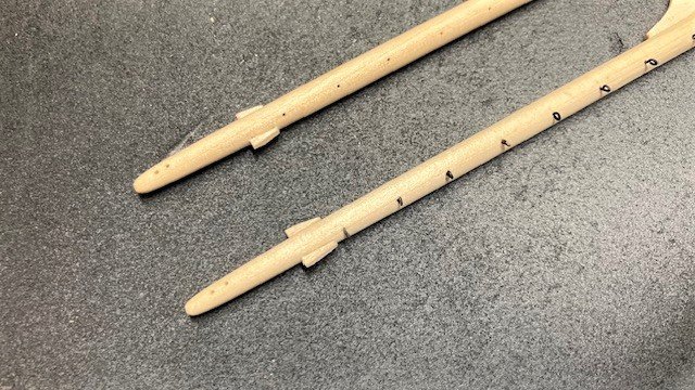
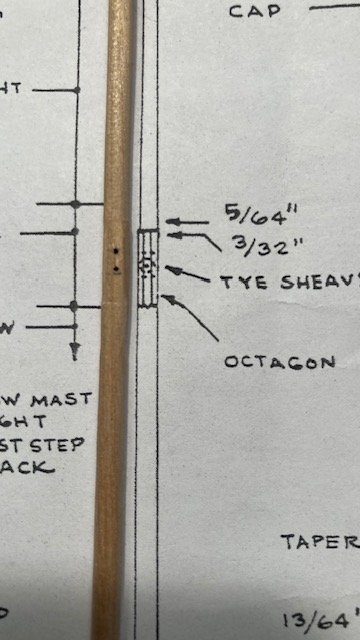
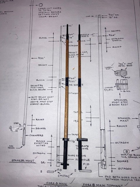
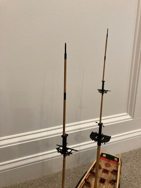
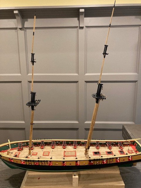
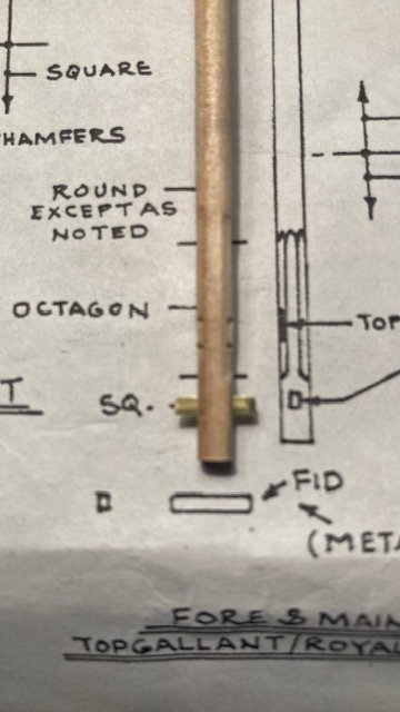
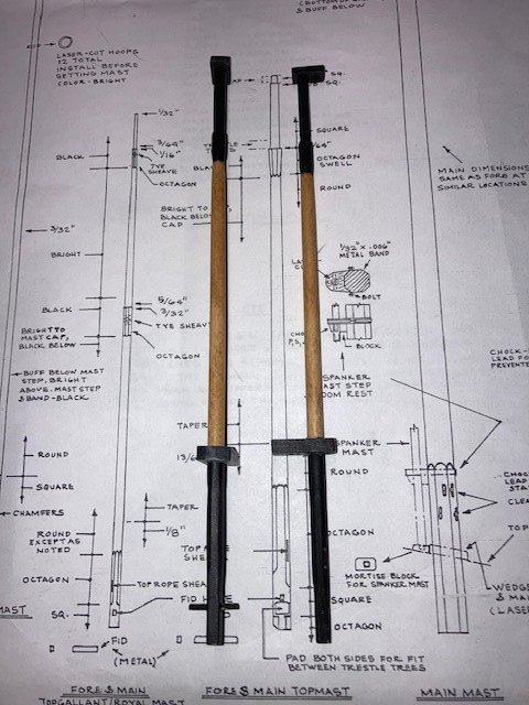
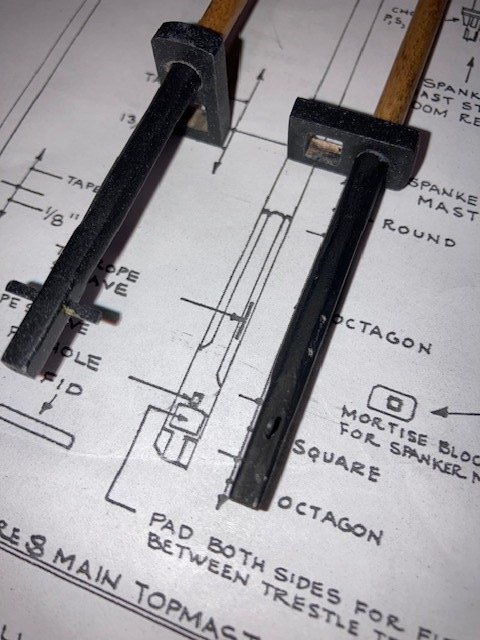
Fashioned the Main and Fore Topgallant Royal Masts. A lot of sanding/filing required to shape these as per the plans. I left the tip of the mast a little thicker for fear of breaking it off if too thin. I used the top mast cap as a guide in shaping the mast. Made the faux sheaves for the .010” Topgallant Royal Tye Halliard and the .016” Topgallant Tye Halliard. Note: The kit is not furnished with .010” line. I plan to use .012” for the Royal Tye. I also made the faux sheave for “Top Rope.” I have not found the Top Rope that passes through this sheave anywhere on the plans. If anyone knows what this is, please feel free to let me know. For the fid, I used a 1/64” x 1/16” brass strip. The masts were finished as per the plans. For the “bright” finish I used Minwax Golden Oak. I applied a coat of Minwax Polyurethane. Next up, the Fore & Main Course Yards.
.jpg.7e56004364d6d0b8b5e2cea8242ccae6.jpg)
.jpg.5790450cea8ec83b23054c729711b5ab.jpg)
-
Thanks for the compliment. Glad you're enjoying the log.
-
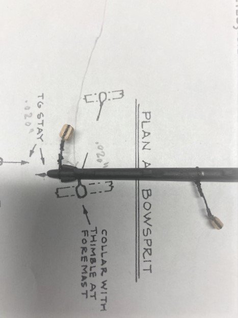
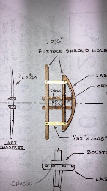
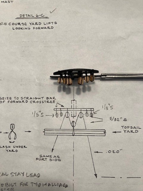
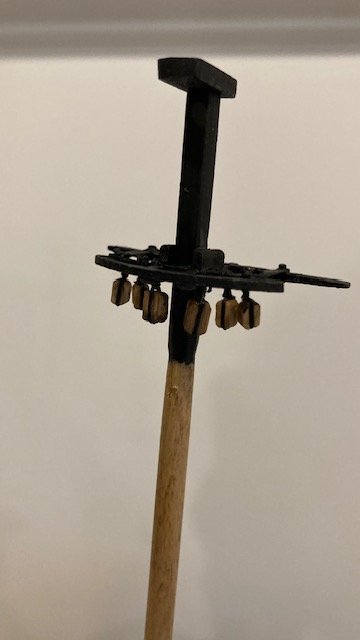
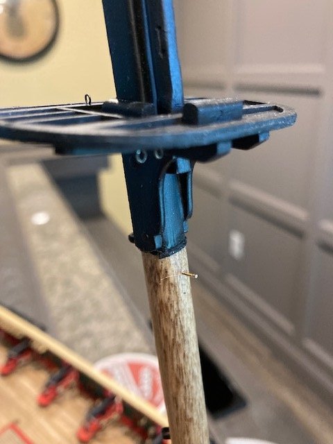
Stropped the lower 3/16” closed heart for the Main Preventer Stay and attached it to the eyebolt in the Bow Sprit Bitts. I used 30 gauge wire for the “iron strop” and a Syren closed heart. Added the iron stropped 3/32" bullseyes (not furnished with the kit) for the Main Mast Stay and Spring Stay Lead. I used 28 gauge wire to strop the bullseyes. Added the 1/8” hooked blocks for the Main & Fore Course Yard Lifts. The 3mm hooks are from Crafty Sailor. Next on the To Do List, the Fore & Main Top Mast Crosstrees. Fashioned the Top Mast Crosstrees. The thickness of the straight and curved members of the laser cut Crosstrees are slightly thinner than the plan. Consequently, there’s a gap between the straight and curved crosstree members and trestle tree notch. I filled the gap at the curved crosstree member with wood filler. I will make the bolsters slightly longer to cover the gap at the straight crosstree member. Holes have to be drilled in the laser cut crosstree and the aft crosstree for the futtocks shrouds. The plans call for the shrouds to be .016” line. The kit is not furnished with .016” line. I’m planning on using .018” line purchased from Syren. The crosstrees are very thin so, before drilling the holes, I applied CA to the ends of the crosstrees to prevent them from splitting. I primed the crosstrees and spray painted them black. Next, I stropped the four 1/8” single blocks for the bunt lines and leech lines and two 5/32” single blocks for the top sail halliards and seized them to the straight bar of each forward crosstree. I used the kit supplied blocks. They’re not as pretty as the Syren blocks, but they serve the purpose. Note: Be sure to check the orientation of the blocks before seizing them. The bolsters were added and the crosstrees were permanently attached to the top mast. Just as a matter of observation, the scale of the crosstrees appears to be out of proportion with the rest of the ship. Also, as a reminder, if you fashion the crosstrees off mast and install the collar with thimble on the fore mast, as I did, you will need to hold off installing the chock in the trestle tree until after you slide the crosstree over the top mast. The alternative would be to install the collar after the across tree is installed. Next up, the Topgallant Royal Masts.
.jpg.4497b2ef39d44fdb6af3f5e81662be59.jpg)
-
Well, thank you. I don't consider myself to be an expert model ship builder, though I have done several. Each model has it's own level of difficulty that requires performing tasks that you may not have done before - it's a perpetual learning experience.
-
I guess I misinterpreted the comment. Yes, it would be a complement.
-
Not sure where you're coming from, as I'm not building the Perseverance. I'll take your recommendation as a subtle putdown.
-
Thanks for bringing this to my attention. I can see that the blocks need to be aligned with the yard arms. I hadn't permanently affixed the blocks, so this was easy fix (see photos).
-
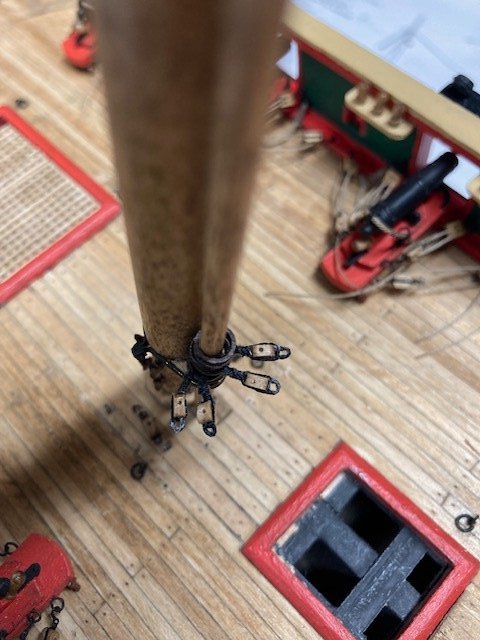
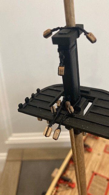
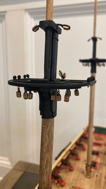
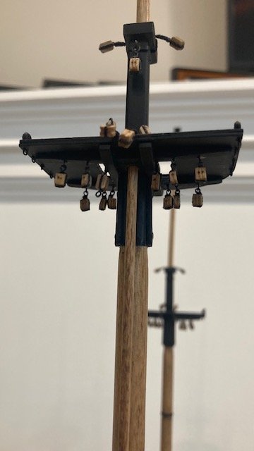
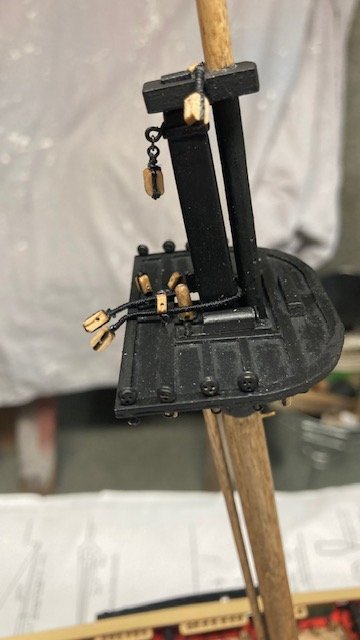
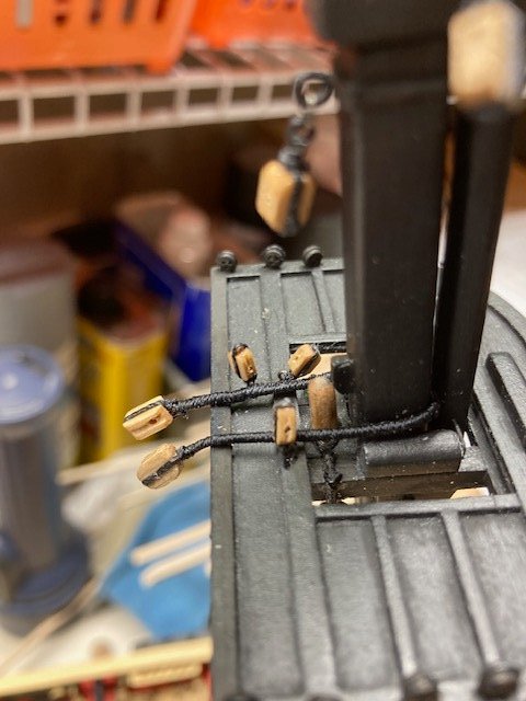
In my earlier post, I talked about the eyebolts in the top of the Main and Fore Tops. In reviewing the plan sheets, I discovered that I missed an eyebolt in the Fore Top for the Main Topgallant Stay Lead (Detail 5-D). So, the Fore Top has 5 eyebolts. On the port side there are 3 eyebolts: the Main Topgallant Stay Lead Tackle, and the Topgallant Halliard tackle and the Topsail Reef Tackle (Detail 6-F). On the starboard side there are 2 eyebolts: the Reef Tackle and the Main Royal Stay Lead Lanyard (Detail 5-F). Note: The Topgallant Stay Tackle is made up with a fiddle block. Fiddle blocks are not included in the kit. The Main Top has 3 eyebolts, 2 on the port side for the Topsail Reef Tackle and the Topgallant Halliard tackle, and 1 on the starboard side for the Topsail Reef Tackle. I found the plan sheets to be a little confusing relative to the number and location of eyebolts on the Tops - I hope I've clarified that. I think I’ve completed all of the blocks that get attached to the Fore and Main Tops and Mast caps (see photos). Most noteworthy are the 3/16” single Topping Left Blocks. A note on Sheet 5 says the blocks are stropped over the aft crosstrees and seized around the mast. The only way that this could be done is if there is opening in the Top, which there is not, to allow the block strop to pass over the crosstree as shown on the rigging profile. These blocks on the actual Niagara ship pass over the top (see photo). That’s the way that I set mine up. At this point in the build, I’m going to try to set up the blocks and the bullseyes that are attached to eyebolts in the deck.
.jpg.8ea95f7c5aae145fdf780648e650031e.jpg)
.jpg.8d934068a982368aad5856baa10bad75.jpg)
-
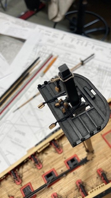
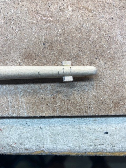
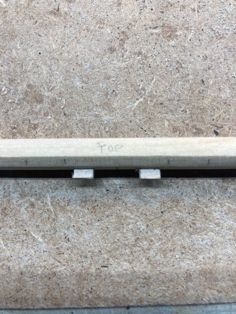
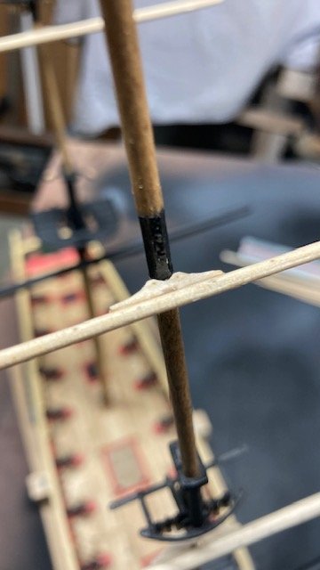
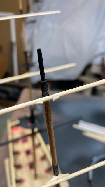
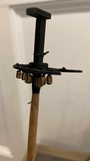
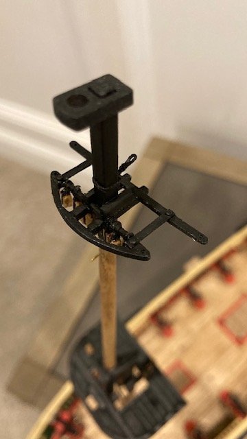
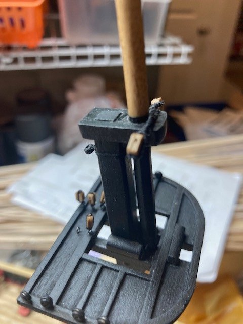
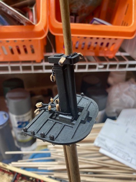
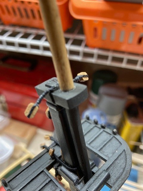
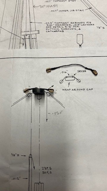
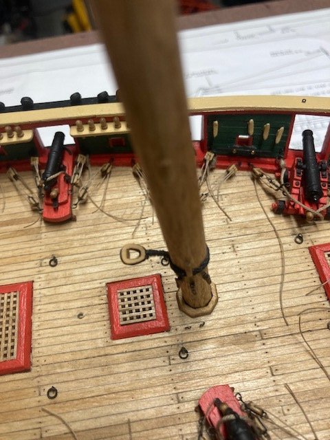
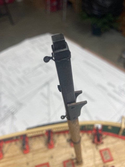
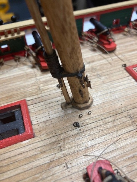
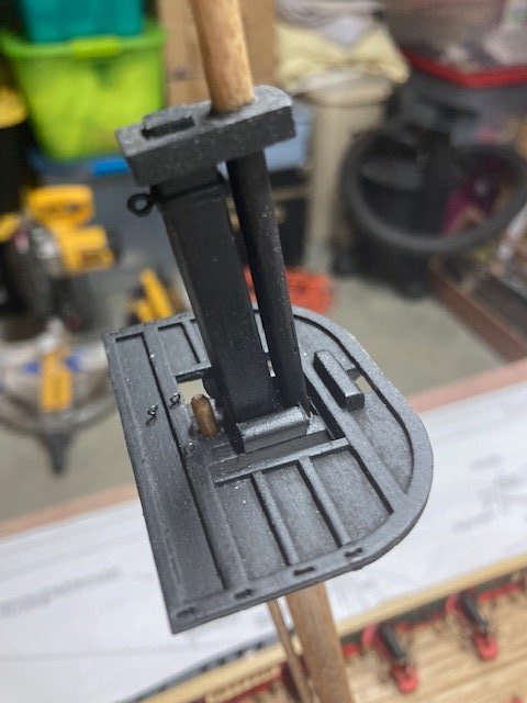
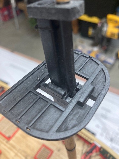
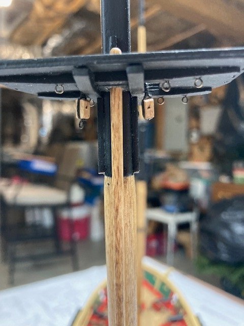
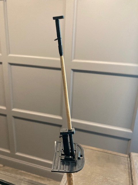
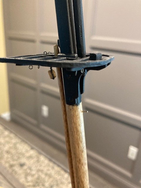
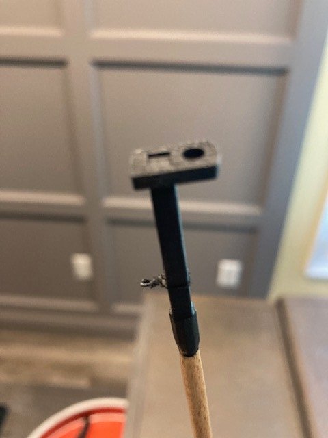
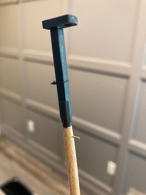
Finished the Spanker Mast. Managed to salvage all but one of the laser cut hoops. They are very difficult to remove from the laser board. They’re supposed to be finished “bright” (natural). I removed some of the char from the hoops but not all for fear of breaking them. The plans call for the Spanker Mast to be painted “buff” below the “step” (Spanker Boom rest) and black above the step. From what I have seen from other build logs, most finish the Spanker Mast in “buff.” I decided to finish the entire mast “bright.” (Golden Oak). Because of the char on the hoops, I decided to stain them Minwax Red Mahogany stain. I coated them with polyurethane. Fashioned the little mortise block for the Spanker Mast and glued it to the mast wedge. Note: When you install the Spanker Mast, leave the top of the mast a little above the block for the spanker hole so that you can add the sling for the 5/32’ single blocks for the Spanker Gaff Throat Hillards as shown in Detail 5-J. Completed the Fore and Main Top Mast. They require a lot of filing and sanding to create the “octagonal swell” near the top of the mast in addition to the square sections. I didn’t bother to create the short octagonal section at the bottom of the mast because it won’t be visible. Also, the mast has a “top rope sheave” near the bottom of the mast. I’ve studied the plans and cannot find a “top rope” that passes through the sheave. In reviewing other build logs, I did not find any that added the sheave to the top mast. Nonetheless, I decided to add a faux sheave. Also, the plans note that the fid is “metal,” so I used a 1/64” x 1/16” brass strip – it’s not quite as thick is the plans show but it’s much easier than fashioning one from wood. Besides, it won’t that visible in the final analysis. I finished the mast as per the plans. The applied paint/stain adds to the thickness of the mast, so I had to enlarge the circular opening in the cap in order to slip it over the mast. I find that the black paint seems to hide a lot of the detail in masts. Reviewing the plans for miscellaneous items that should be added to the masts sooner rather than later, I added the following: 1)The closed heart for the Main Stay on the Fore Mast (Detail 5-C) - I used a Syren 5.5mm closed heart instead of the laser cut heart furnished with the kit. The collar was made with .028” rope. 2) The collars for the Spring Stay and the Top Mast Stay - I used 2.5mm bullseyes for the thimbles, painted black. 3) The 5/32" single blocks for the Spanker Gaff Throat Halliards (Detail 5-J) - I added an eyebolt to the port side block for the Spanker Throat Halliard line. and 4) The collar for the main topgallant stay (Detail 5-D) on the Fore Top Mast. I also decided to added pins to the Main and Fore Masts and the Top Masts for securing the the Coarse Yards and Top Sail Yards, respectively. Next on the To Do List, the blocks beneath the tops and the deadeyes.
.jpg.e3778a37f57ad6502c88a4afb1e22089.jpg)
.jpg.12d531ef2f7bbb35af71fa03ff629261.jpg)
-
Thanks for the compliment. I'm glad my build log is helpful - that's the intent. I try to point out discrepancies on the plans and to reference plan details to make it easier to follow my blog. When I review other build logs, I'm always on the lookout for items that are best added sooner rather than later. Your ship is progressing nicely.
-
Yes, I choose the the Niagara because it is very similar to the Syren.
-
Nice work. I'll definitely keep an eye on your build log as I progress on mine.
-
Thanks for the complement. You are correct. Good pick up. If you look close you'll see an indentation just to the left of the eyebolt that is filled in with paint. That's where it should be. I'll leave the incorrect eyebolt where it is and just add another in the correct location. Sail on.

.jpg.281d6ed7e6a6661bd16dda8b097cc1e0.jpg)
.jpg.b1cf2b46504f718d679f56e7a1508737.jpg)