

coxswain
-
Posts
109 -
Joined
-
Last visited
Reputation Activity
-

 coxswain reacted to James H in 1:32 Fifie – The Scottish Motor Fishing Vessel by Amati
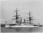
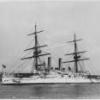
1:32 Fifie – The Scottish Motor Fishing Vessel
Amati
Catalogue # 1300/09
Available from Amati for €220.00
The Fifie is a design of sailing boat developed on the east coast of Scotland. It was a traditional fishing boat used by Scottish fishermen from the 1850s until well into the 20th century. These boats were mainly used to fish for herring using drift nets, and along with other designs of boat were known as herring drifters. While the boats varied in design, they can be categorised by their vertical stem and stern, their long straight keel and wide beam. These attributes made the Fifies very stable in the water and allowed them to carry a very large set of sails. The long keel, however, made them difficult to manoeuvre in small harbours. Sailing Fifies had two masts with the standard rig consisting of a main dipping lug sail and a mizzen standing lug sail. The masts were positioned far forward and aft on the boat to give the maximum clear working space amidships. A large Fifie could reach just over 20 metres in length. Because of their large sail area, they were very fast sailing boats.
Fifies built after 1860 were all decked and from the 1870s onwards the bigger boats were built with carvel planking, i.e. the planks were laid edge to edge instead of the overlapping clinker style of previous boats. The introduction of steam powered capstans in the 1890s, to help raising the lugs sails, allowed the size of these vessels to increase from 30 foot to over 70 foot in length. From about 1905 onwards sailing Fifies were gradually fitted with engines and converted to motorised vessels. There are few surviving examples of this type of fishing boat still in existence. The Scottish Fisheries Museum based in Anstruther, Fife, has restored and still sails a classic example of this type of vessel named the Reaper. The Swan Trust in Lerwick, Shetland have restored and maintain another Fifie, The Swan, as a sail training vessel. She now takes over 1000 trainees each year and has taken trainees to participate in the Cutty Sark Tall Ships Races to ports in France, Denmark, the Netherlands, Ireland as well as around the UK.
Extract from Wikipedia
The kit
Fifie is packed into a large, heavy box that certainly hints that there’s a good quantity of material included to build this historic fishing vessel in all its glorious 1:32 scale. I do admit to particularly liking this scale, having built plastic models for many years and indeed for magazine publication. It’s definitely something I can relate to when eyeing up the various dimensions and features. Amati’s presentation is flawless and certainly stands out, with its large, glossy lid that captures an attractive view of the Fifie. It has to be noted here that the hull is usually fully painted, with green being common above the waterline, but this model was finished to show off the beauty of the walnut timber supplied in the kit. And why not! For those that don’t know, this kit, under the Victory Models label, was designed by Chris Watton. Many of you should be familiar with that name and his design pedigree. At 1:32, this kit is no shrinking violet in terms of size. Fifie is 700mm long, 470mm wide and with a height of 230mm (sans masts).
Lifting the lid does indeed show a box crammed with materials. Inside, we have several bundles of timber, plus a packet of timber dowel/strip/metal rod/tube, a thick packet containing numerous laser-cut sheets, another packet with plans and photo etch, and underneath the main timber, we have sail cloth and fittings packs. Thick foam is included to stop the main materials from banging around in the box.
Strip wood
Fifie has a double-planked hull, with the first layer being constructed from 1.5mm x 7mm lime strips. These, like many of the other bundles, are 600mm long, and very cleanly cut with no fuzzy edges Sixty-five of these are supplied. The same quality goes for the second planking layer, which is supplied as 90 strips of 1mm x 6mm walnut which is some of the best I’ve seen in a kit. There is little colour variation in these, and they look pleasantly uniform. I’ve always found Amati’s timber quality to be exceptional and this is no different. As well as elastic to hold the bundles some labels are also included to help identity the material.
Other strip wood is included (beech and walnut) for such things as deck planking, caulking (yes, caulk plank!), lining the various deck hatches, sheathing the deckhouse structures, rubbing strakes etc. These bundles are both taped and bound with elastic, with the deck planking having an identifying label also. Cutting is clean and precise.
Dowel and tube/rod
Various lengths of dowel is included for masting, false keel strengthening pins etc. and thicker strip wood for the timberheads. All is supplied in a nice uniform walnut colour….no nasty walnut dyes/stains in this kit! These latter lengths are also packaged into a thick clear sleeve, unlike the others. Note also various lengths of brass and copper wire, as timberheads well as some copper tube. Some mounting parts are included for RC conversion, but you will need to purchase other items to complete the model for radio.
MDF sheet items
Again, Amati has made extensive use of 4mm MDF for the hull false keel and bulkheads, and all are laser-cut, as are all individual wooden items in this kit. Cutting looks very precise with very little in the way of scorching, apart from very localised discolouration. I know many don’t like MDF as a material for our models, but MDF sands easily and is also warp-free, lending itself to a nice, true hull. You won’t see any of this when you start to lay planks. There are FOUR sheets of this material, and you’ll notice that there aren’t any parts numbers engraved on here. You will need to refer to the first two sheets of plans which contain the parts references.
A single sheet of 2mm MDF contains parts such as the four-piece deck, cleats, and the bulkheads and keel for Fifie’s single launch vessel.
There is also a single 6mm sheet of MDF (sheet 2698-B) which contains the four parts needed for the cradle. I’ve seen numerous sites which now sell this model claim that no stand is included with this model. Well, this sort of proves that statement incorrect. This is the same cradle shown on the box lid images. Of course, you’ll need a suitable MDF primer for this, and some nice coats of gloss lacquer to get the best from this.
Ply sheet parts
SIX sheets of thin ply are included for just about every other timber construction elements of Fifie, including the deckhouse, deck superstructures, keel sheathing, and bulwark capping strip. Again, all parts are laser-cut and will require minimal effort to remove any edge char.
Fittings
Two boxes of fittings are included in the very bottom of the Fifie kit box. Some of the weight bearing down has caused a small crack in the two vac-form fittings boxes, as you can see, but all parts within are absolutely fine. The first box contains the cast metal propeller, deck buckets, ship’s wheel, rigging blocks, life preserver rings and a whole load of beautifully smooth wooden balls for making the many buoys which sit on Fifie’s deck. These are perfectly circular, yet the ones on the box image are slightly shaped. Instructions show these as the balls, and you could perhaps opt to use a little putty to add some shape to these.
The second fitting box contains seven spools of rigging cord in both black and natural colours, nails, various cast fittings such as bollards, plus rudder pintles, anchors etc. Copper eyelets, chain and ferrules etc. make up the set.
Sail cloth
Should you wish to add sails, then enough material is supplied for you, in bleached white cloth.
Photo-etch
Very few kits come without photo-etch parts these days, and this is no exception, with TWO sheets of 0.7mm brass with a very high number of included parts. A quick scan around the sheets will easily identify parts for the mast bases, steam winch, engine skylight, capstan, deck hand pump, wheel assembly, herring shovel, tabernacle, mast rings, etc.
Acetate and card
I have to say I’m not entirely sure what the card/cartridge paper is for except for maybe general use, but the thin acetate is obviously for the cabin windows.
Instructions and plans
Without a doubt, Amati produce some of the very best instruction manuals to come with any model kit. For reference, check out my Orient Express Sleeping Car review and that of Revenge. Fifie is no different with a luxurious and fully-pictorial, 64-page publication. Whilst this isn’t perfect-bound as with the previous reviews, it is in full colour and produced to a standard that’s still far higher than many contemporary manufacturers, with each stage being shown under construction so you get a perfect idea about what is required at that point in construction. Text is also in English, or at least in the sample I have been sent. The rear of the manual contains a complete components list.
Backing up this publication is a set of seven plan sheets. The first two of these are for identifying the various timber and PE parts. The others show general profile and detail imagery, as well as masting and rig drawings. Remember that the hull itself is built entirely from the photographic sequences so everything you see on these drawings is for external details.
Conclusion
I have to say that you get a lot of kit for your money with Fifie, and when I first asked Amati what they envisaged the RRP to be, I was quite surprised at this. Everything about Fifie is quality, from the packaging and presentation, to the beautiful, photographic manual, fittings, sheet and strip timber, all the way to the superbly drawn plans. I’m very surprised that the gestation period has taken so long for them to bring this excellent kit to market. It’s also a Chris Watton thoroughbred. If you’ve seen his previous designs, then you’ll be familiar with the format of Fifie, which was quite the different vessel for Chris to tackle, when everyone seemed to think he would only design fighting vessels, armed to the teeth with cannon. I must admit that Fifie did take me quite by surprise too. The very shape of this iconic and historic vessel is so homely and welcoming and for me, invokes images of those times when fishing communities were happy and thriving. Whether you’re a fan of Chris’s work or not, Fifie is most certainly a kit that you should consider dropping into your virtual shopping cart next time you visit your favourite online model ship/boat retailer, and of course, if RC is your thing, then this kit will also suit your genre!
VERY highly recommended!
My sincere thanks to Amati for sending out the sample kit you see reviewed here. To purchase directly click the link at the top of the article to take you to Amati’s online shop or check out your country’s local distributor. Plans are also available from Amati, for €21.00
-
coxswain reacted to ERS Rich in USS Maine by ERSRich - FINISHED - BlueJacket Shipcrafters - 3/32
Progress Photos
Not as much time for the shop the past few weeks - spring projects, trouble with the house boiler, amongst other things. Should have more time for the shop in the weeks ahead. Hoping to wrap this up by the end of May.
Working on completing the mid and aft superstructures. Same processes used for the fore superstructure.
And beginning to build the sub assemblies for the run up to final assembly. Ahead is the PE for the catwalks, cranes, etc.
Here is the mid superstructure in the tail vise, with a plastic piece on the left acting as a caul, to apply pressure on the curved forward end plywood skin.
Next is the mid superstructure with plywood installation around the perimeter complete.
This picture shows applying the 3/16” half round. A spacer block is used to position the middle piece.
A few of the sub assemblies - 6 pounder gun tubs note the tiny hand wheels, and the deck winch.
Mid and aft superstructures dry fitted.
Have a great weekend!
-
 coxswain reacted to KeithAug in Germania Nova 1911 by KeithAug - FINISHED - Scale 1:36 - replica of schooner Germania 1908
Hi Keith, I think the critique of experts is by far the most valuable resource and what better review group that all my MSW friends.
Gary, Eberhard, Andy, Gus - thank you all for your comments.
I not getting much modelling done at the moment. My son and daughter have added to my wife's list of home improvement jobs. Never mind.
I am approaching the end of my build log photos but here is the next batch. Probably two more batches left after this lot.
-
-
coxswain reacted to Henke in HMS Agamemnon by Henke - Caldercraft - 1:64
Thanks for all the likes and comments. I do not know if I deserve it but at least it is encouraging. I am not a very skilled modeler but at least this shows what can be achieved with with a well thought out model as Caldercraft's Agamemnon in combination with perseverance. This week's work has been focused om the hammock cranes along the sides. I hope the pictures are OK. I see the model is a bit dusty....
Best regards
Henrik
-
coxswain reacted to gsxdent59 in San Ildefonso by gsxdent59 - OcCre - 1/70
Now i finish the foremast with the four yards placed but not cement. I will make the other two masts in the same way..
-
coxswain reacted to md1400cs in Sovereign of the Seas 1637 by md1400cs - Sergal - 1:78 - to be hopefully bashed
Hi Mates,
Kevin: thanks your post is much appreciated
Been a while since I’ve updated – small update on current work – very part-time in shipyard these days (;-(( - other "things" have absorbed my free time)
---- Had always intended to allow a limited stern view to the inside through side upper and lower windows as well – so did not use Sergal instructions that just applied side window frames against hull timber. (note their instructions image FYI)
So, this area (my first image) is a disaster that had little foresight on my part. And will need lots of work…But I also knew that challenges would hopefully lead to better looking results than following straight “out-of-the-box” instructions IMO.
Short text -- images do most of the communicating.
Thanks so much for the many taking a look and the likes,
Regards,
-
coxswain reacted to wade13 in Sovereign of the Seas 1637 by md1400cs - Sergal - 1:78 - to be hopefully bashed
More than a model ship designer, a full shipwright and your work is incredible. At every juncture, you question and redefine, until you feel and know the Sovereign like very few others (including those of the 17th Century). I feel like the child of time, sitting up high in dry dock, swinging my legs as I watch captivated; eating dry milled bread and a chunk of cured cheese. Practical, perfectionist and the patient beyond belief... you truly are a shipwright and have made me love the craft. Thank you
-
coxswain reacted to WalrusGuy in USF Confederacy 1778 by WalrusGuy - Model Shipways - 1:64
Thank you so much for the kind words and the 'likes'😄
I have been slowly working through the window frames. I finished the portside frames.
For the angles windows, I used the kit supplied ones as a guide. Here, I glued the two outer strips and used the kit frames to get the right angle by letting the glue set as the strips rest on the edges of the kit piece.. After letting the glue set and doing the same on the opposite corner, the 2 'L' shaped pieces were then glued together, followed by all the internal strips:
Here are a few photos of how it looks on the ship (only dry-fitted for now):
I got to say, all this is really really fiddly work. Getting the notches in the correct spots on each strip is very tricky. Had to discard twice as many as those that made the final round!
-
coxswain reacted to ERS Rich in USS Maine by ERSRich - FINISHED - BlueJacket Shipcrafters - 3/32
Finishing the Forward Superstructure
The completion of these steps bring us to page 16 of the instruction book.
Filed the parting lines from the metal fittings. File set purchased at Home Depot.
Next primed the fittings with Mr Primer, thinned with Mr. Color; then painted with XF-26.
Next made a photocopy of the deck, cutout the openings for the fittings, and installed them. And removed the template.
Next installed the bow break. The challenge here is to get adhesive on the thin edge of the styrene without a mess. So dry fitted the break, applied tape on the deck along the edges, removed the break, applied adhesive to the deck, reinstalled the break, slowly removed the tape before the adhesive dried.
Finally installed the hatch coamings, and cleats. Cleats by Syren Ship Model Company
-
coxswain reacted to ERS Rich in USS Maine by ERSRich - FINISHED - BlueJacket Shipcrafters - 3/32
Progress Photo
Turrets painted. Turrets and gun barrels dry fitted. Happy Friday!
-
coxswain reacted to ERS Rich in USS Maine by ERSRich - FINISHED - BlueJacket Shipcrafters - 3/32
Painting the Waterways
An exercise in masking….
Used Tamiya 3mm tape as a spacer at the edge half round hull trim, then masked along its inside edge, and construction paper to mask the remaining deck.
Then removed the white tape. Not shown is I masked the top edge of the half round.
Then painted the waterway Tamiya Desert Yellow XF-26, with Paasche Talon #2 tip. Next masked over the waterway and painted the top edge of the half-round white.
-
coxswain reacted to ERS Rich in USS Maine by ERSRich - FINISHED - BlueJacket Shipcrafters - 3/32
Progress Photos
Pleased with the results.
-
coxswain reacted to ERS Rich in USS Maine by ERSRich - FINISHED - BlueJacket Shipcrafters - 3/32
Hull Painting - Dark Green
Leveled the model and marked the waterline.
Set the model on its side on a red rag, and applied a single continuous piece of Tamiya masking tape along the marks. Then lightly burnished the tape with a wooden tongue depressor.
Finally used construction paper to make a skirt around the model. Applied Tamiya XF-26 Deep Green with the Iwata RG-3 mini sprayer @20#.
-
coxswain reacted to iosto in Enterprize by iosto - FINISHED - CAF - 1/48 scale - adding complete interior
Basic construction
-
-
-
coxswain reacted to cafmodel in La Renommee 1744 by cafmodel - CAF - 1:48
Updated transparent resin
Updated hooks and some accessories
-
coxswain reacted to cafmodel in La Renommee 1744 by cafmodel - CAF - 1:48
Work has been resumed in recent days, and metal casting parts are currently being made
The internal structure part will be finished immediately, and the preparation of instructions and production will begin later
Please forgive me, I just finished my worst year,Delayed a lot of work。
-
coxswain reacted to Tomculb in USS Constitution by TomCulb - FINISHED - Model Shipways - 1:76.8 - cross-section
Assembling the fighting top is pretty straightforward. The laser cut floor and a small frame around the perimeter fit together precisely. The center cutout in the floor has a center mark, which greatly facilitates gluing the timbers in place. I drew the various lines running outward from that center mark. The instructions suggest determining the location of the aft timbers directly from the plans rather than using the center mark, but I don’t know why. The timbers overlap the frame forward, and cutting the notches to accommodate them turned out to be easier than I expected. And consistent with expectations, the laser cut upper crosstrees fit precisely.
There are also four laser cut cleats which can be seen in the second picture below. After gluing them in place I saw in the instructions quite a few pages ahead that at least a couple of them will be used to secure some lower yard rigging, and I have some concern that they may be too flimsy for the job. A challenge for another day . . .
The underside of the fighting top is as straightforward as the top side. The laser cut lower crosstrees and trestle trees fit precisely as expected. Same with what are referred to as the “thumb cleats” and their cast metal sheaves. I painted the sheaves black, I guess out of a tendency to leave no metal piece untreated, but so painted they become almost invisible. The instructions have you glue one trestle tree in place (3/16” off the center line) and leave the other one unglued, presumably to allow for a tight fit when it's time to glue the fighting top to the mast. I preferred to leave both trestle trees unglued.
Next I painted the whole thing white, then mixed up some light gray to paint the upper side of the deck. Finally I painted white half (horizontally) a 1/8 x 1/32 strip, and after soaking it, and with the help of an old iron, carefully wrapped and glued it around the front and sides of the fighting top.
A few eyebolts and some deadeyes will finish this stage of the fighting top. The instructions have you build and install the guard rail much later in the build.
Note added two months later -- part of a caption to a photo on page 56 of the instructions says "18 eyebolts added to various locations." Those eyebolts are not mentioned in the instruction text, and I completely overlooked that photo caption. Ten of those eyebolts are supposed to be added to the top of the fighting top, just inboard of where the deadeyes will be installed, and those ten eyebolts will eventually anchor the royal and topgallant shrouds. Easier to add them at this point in the build than where I am now (with deadeyes in and fighting top installed on the mast), but fortunately I have not yet installed the topsail shrouds, which would have made the job almost impossible.
-
coxswain reacted to Tomculb in USS Constitution by TomCulb - FINISHED - Model Shipways - 1:76.8 - cross-section
The last couple of weeks in the shipyard got increasingly challenging, putting together the gun and spar deck outer walls and framing the gun ports.
Things started easily enough . . . a laser cut wall for each side, spanning two decks. As usual the laser cutting, and the scribed detail on the outer sides, are very good. Both were painted black, with the white gun stripe. It’s beginning to look like a war ship!
At the spar deck level the wall is a consistent 3/16” thick, inner and outer walls being 1/16” each, and what the instructions call “braces”, also 1/16” thick, between the two walls. Those braces are cut from 1/16” x 1/8” stock, and they frame the gun ports and provide gluing surfaces between the walls (in addition to the ribs). I cut all 20 pieces at the same time, labeling them as you’ll see in the next photo of the port side.
At the gun deck level, the inner and outer walls spread farther apart, and the braces at that level are laser cut. They are helpfully scribed B, M, M and S, for bow, middle, middle and stern. As cut, they are actually maybe 1/8“ too long, and in cutting them shorter I overdid it a bit, but no matter.
About a month ago (first picture below) installing the inner wall on the starboard side I confronted the fact that the middle rib on that side extends outward out of line with the forward and aft ribs. I don’t know whether the laser cutting of that middle rib is at fault, or whether I was sloppy in putting the ribs and the base together last spring, but it’s an issue that gets worse the further away you are from the keel. To deal with it when installing the inner wall, I glued a 1/32” shim to the inside of the inner wall.
In the second picture below that problem is not obvious, but you can see that I had started trying to thin that plywood rib by sanding it, which I quickly realized would be inadequate. What I eventually did was to cut the rib off at the level of the spar deck, and then glue another 1/32” shim to the one already there, so that this replacement rib is the requisite 1/16” thick. Below the spar deck I thinned the rib with a lot of grinding with my cordless Dremel tool, followed by a lot of sanding, to get that rib to conform with the other two. Unfortunately I didn’t take any pictures of that process.
Nor did I get pictures of what follows. I think I was too focused on what proved to be a difficult task. I tackled the port side first.
The gun ports are framed with laser cut 1/16” pieces. The instructions have you glue the outer walls to the ribs and braces, carefully aligning the gun ports as best you can. They then have you assemble the gun port framing, building little boxes that you then slide into the ports. I built the port side frame boxes as instructed, then tried to use them to help align the sides when gluing the outer wall on. To make a long story short, at the gun deck level the outer wall ports simply did not align very well at all with the inner wall ports.
More on that later, but first a few words about the frames. At the spar deck level, they are simple four sided boxes 3/16” deep. Oddly they are not even mentioned in the instructions, but they are identified in a caption to one of the photos in the instructions. At the gun deck level, they are slightly more than 3/16” deep at the top, and deeper than that at the bottom. So the top and bottom pieces vary slightly in width (something that is easy to overlook), and the side pieces are somewhat trapezoid in shape. These frame boxes also differ from the ones at the spar deck level in that another frame box fits inside them, flush on the inside edge, and inset 1/16” from the outside edge. I think the reason for this double framing is to provide for a ledge for the gun port lids to rest against when they are closed. I took the approach of building the outer box first, then gluing the sides of the inner box to the inside of the outer box.
Sliding and gluing the port side spar deck frames into their respective ports went reasonably well, but I was still left with gaps between the frame and the wall along the sides, as can be seen in the picture below. Most of the gaps I filled with paint, but I pulled out the offending frame shown below and rebuilt it.
At the gun deck level, the frames simply wouldn’t fit at all, and I had to do a lot of shaving of the inner wall with my Xacto knife, followed by some sanding, to get them to fit. Needless to say that was nerve wracking, as I didn’t want to do any damage to the long guns and their rigging. And of course my fat fingers and thumbs pretty well blocked any view of what I was doing. The end result, after doing some cosmetic work, wasn't bad. The second picture is obviously after gluing the wales in place.
On the starboard side I decided to take a different approach. Rather than build frame boxes, I would glue the frames piece by piece into their respective ports. That worked OK on the spar deck level, although I can see I lft some gaps.
On the gun deck level, as on the port side the gun deck outer wall ports did not align well at all with the inner ports, and a great deal of shaving and sanding was needed so that the frame pieces could be glued in. The misalignment was mostly longitudinal; that is, the inner wall port was a few millimeters aft of the outer wall port, and the forward side of those ports had to be cut back. What I didn’t think about was the fact that the aft side of those ports was of course misaligned as well, meaning that the outer wall obscured the fact that the edge of the inner wall was a few millimeters aft, leaving an uneven surface to glue the frame piece to.
On this starboard side I need to do some cosmetic work, but I’m not sure exactly what to do. Actually I do know what to do . . . take a break from working on the ports and move on to planking the hull. I’ll ome back to the ports when it’s time to put in the port lids and when I’m fresher and and maybe have a little more positive attitude about the work I'm doing.
-
coxswain reacted to Tomculb in USS Constitution by TomCulb - FINISHED - Model Shipways - 1:76.8 - cross-section
This screenshot from Google Maps shows pretty well what I was trying to describe in my post last night with regard to the forward hatch, and lack of stairs at the forward end of the model. This is looking forward, and as you can see, the stairs are way forward of anything on the model, which ends at the gangplank seen to the right of the picture.
And for those who didn't get it earlier in this log, here's a link to the Google Maps tour of the Constitution:
https://www.google.com/maps/@42.3724493,-71.0566215,3a,75y,348.92h,69.87t/data=!3m7!1e1!3m5!1sAF1QipM4G2XOGUOPxXyh5KTrPENhbU6pK3SX4vS-n90P!2e10!3e12!7i13312!8i6656
-
coxswain reacted to Tomculb in USS Constitution by TomCulb - FINISHED - Model Shipways - 1:76.8 - cross-section
Shaping, painting and installing the waterways was pretty familiar and uneventful, with one exception. On the starboard side the center rib is about 1/8th” out of line with the fore and aft ribs, making a graceful curve which doesn’t match the virtually straight waterway at all. At first I thought I would bend the waterway to fit the rib, but when I dry fit the deck to the waterway, I realized that the deck would need to be shaped pretty drastically to avoid a gap. So I glued the waterway to the frame and other two ribs, leaving a gap between it and the middle rib, which will be hidden between the sidewall and the hull planking.
Next came cutting the hole in the starboard spar deck planking piece, to open up a view of some of the gun deck below. That took a lot of time, patience and care, and I still managed to break both thin strips which connect the midships deck and the deck along the waterways. But installing the deck in two pieces actually made things easier. A lot of sanding and trimming needed to be done in order to get the bits and the mast to fit (all dry fit of course) while keeping the front and back of the deck pieces lined up with the edges of the fore and aft framing beams. And of course the two pieces of the deck had to fit between the two waterways, which required some additional trimming where the two broken pieces came together. But fortunately it all worked out.
Finally I built, painted and stained, and installed the fore and aft hatch framing. Aft was merely a repeat of what I had done previously on the gun and berthing decks. Steps and stairs still need to be built and installed.
Forward things got a bit puzzling. The instructions and Plan Sheet 1 show a pair of stairs leading up to the spar deck, athwartships but not crossing each other as is the case with the aft stairs. Plan Sheet 2 doesn’t show any forward stairs but does show grating filling both the aft and forward hatch areas, blocking access to any stairs. Looking at the Google Maps views of the ship, it appears that the forward hatch which is part of the model is part of a large hatchway, maybe 15 feet long or so, covered with grating, most of which extends forward beyond what can be shown in this model. At the forward end of the hatch is a pair of stairs which run fore and aft rather than athwartships. I decided that any such stairs, however oriented, are beyond the scope of this model, and I covered the part of the forward hatch that is part of this model with grating. I don't plan to install any stairs forward.
Then before taking the following pictures, I cut off the forward brace running betwen the forward ribs . . . a milestone of sorts.
-
coxswain reacted to Tomculb in USS Constitution by TomCulb - FINISHED - Model Shipways - 1:76.8 - cross-section
The plans and the photos in the instructions show the handles for the pumps folded back on themselves in some fashion, obviously for storage. Less obvious is exactly how this is done in real life, and stacking them as I did in the first photo below (dry fit) just didn’t look right to me. Nor did it make sense to me why one handle (on the single pump) would be inside the bits coming down from above and the other would be on the outside. I had not yet seen the great Google Maps tour of the Constitution Tom (usedtosail) so kindly alerted us to above. Looking at the second picture below I now realize that the handles on the ship slide onto the ends of the handle arms (or rocker arms as I described them previously) when in use, and they are indeed stacked on top of those arms when stored.
Part of what made this look awkward to me is the bulge at the inboard end of the handle arms. Didn’t look right (IMHO) so I ground one side off so the handles can lie flat on top of the arms, and glued them in place as shown below. Actually I’m not sure I would have done differently even if I had seen the virtual tour of the real thing before glueing the handles in place.
Looking at the photos above, I’ve come to think the whole pump assemblies may be a little too large. Had I been able to slide the handle parts onto the ends of the handle arms as appears to be done on the real ship, the handles themselves would have been above the cannon carriages (especially the cannons stored inboard), leaving no good place to stand while working the pumps. Also the whole things as assembled come close to the height of the beams for the deck above, meaning they would have been at maybe face level relative to an average height man, which certainly doesn’t look very ergonomically efficient. A flaw, though, that is not likely to be noticed by anyone not building the model.
Not relevant to any of this, but I have mentioned previously that the laser cut wood parts are very well cut. As an example, the bits referred to above have a couple of tiny sheaves above decks that would be very difficult to cut with a hobby knife. But upon slicing the tabs that hold the bits to the sheets they come attached to, they dropped very neatly onto my work bench without any hang up on the outboard sheave. Nice work Model Shipways.
Finally, assembling the aft stairs went well, using the jig I posted a picture of back at the end of May. When I installed the gun deck framing more recently, there was some discussion about whether a small section of one of the beams would need to be removed to make room for the stairs. That proved to be the case for me. A combination of Xacto knives with a conventional blade and a saw blade, along with some small sanding implements, got the job done. The stairs then fit nicely into place.
It may be a few weeks before I post again . . . houseguests coming, a little travel, a very minor medical procedure, and a few projects that need to be completed before cold weather settles in. But perhaps most of all, I need to do some thinking about exactly how I am going to cut the starboard spar deck framing and planking pieces so as to best show the gun deck below while giving a hint at the framing that underlies all these decks. It will be fun.
-
coxswain reacted to Tomculb in USS Constitution by TomCulb - FINISHED - Model Shipways - 1:76.8 - cross-section
On most models where you would be working on an open deck, assembling and installing the pumps would probably be pretty straightforward. Much less so here as there is almost always something in the way of what you’re trying to do.
First thing is installing the metal flanges onto the lower part of the six metal pump assemblies, which occurs between the berthing deck and the gun deck. Quality tweezers are a big help; nevertheless I bet I dropped a flange more than a dozen times. I applied some medium thick CA to the pump assembly shaft where the flange would be, carefully lowered the shaft through the hole in the gun deck, then slid the flange onto that shaft and slid it up to the glue. Unfortunately some of the glue is visible in the first picture below, but hardly visible to the naked eye in normal light. Then I glued the assemblies in place, with a drop of the same CA applied to the bottom of the pump assembly shaft and to the underside of the assembly where it rests on the gun deck.
You definitely want to start with the middle pair, so the ones closer to the end are not in the way. In fact I fully installed the four assemblies which are part of the aft double pumps before doing anything with the forward single pumps.
The pump handle assemblies consist of triangular “pump base frames” on either end, “pump arms” attached to a shaft or axle which rotates (on the real thing only) in the base frames, “pump handles” which are pretty much what you would expect, and on the double pump, a pair of “center linkage arms” which go through the deck to operate the pumps you installed a while ago on the berthing deck. No way the shafts for the latter link with these "linkage arms" on the model, but the gap is well hidden by the gun deck and framing. Oddly there are two double and two single pump arms supplied when only one of each is needed, and there are six linkage arms when only two are needed.
“Rocker arms” sounds more descriptive to me so I will use that term instead of "pump arms". I started with the double pump, thinking installing it on the rods coming out of the top of the installed pumps would be pretty straightforward. Until I tried dry fitting it in place. . .
As you can see every piece has to be bent and placed perfectly for things to fit, and the ends of the axle need to be cut slightly shorter. And of course bending these things mars the paint, which I decided not to touch up until everything was installed.
At this point I decided to do the simpler, single pumps first. After doing a lot of dry fitting, I decided to glue the base frames onto the rocker arm axle ends first, then glue the assembly to the deck and the pump rods. That went quite well.
Back to the double pumps and another problem. There is simply no room for the aft base frame to fit between the aft pumps and the stairway frame combing. After giving the situation a lot of thought, I tried thinning the base of the "frame base" with a dremel tool, trying to get the base down to the thickness of the frame. That went remarkably well. For good measure I carved away part of the combing too, which was much harder to do and looks pretty messy. Fortunately that part will be well hidden when this is all finished.
With that fit issue (and all other ones) resolved, and having determined that the “center linkage arms” could be installed later, I slid the slimmed down aft pump frame onto the aft rocker arm axle but did not glue it, applied CA to the bottom of the frame and to the brackets on top of the pump rods, put everything into place, then added a drop of CA to the rocker arm axel, and heaved a sigh of relief.
With that all dry, I then slid the forward frame onto the forward end of the rocker arm axle, and glued it in place. To my surprise, the frame ended up hanging about a millimeter above the deck, because I had not pushed the rocker arms far enough down into the brackets which hold them. Fortunately an almost invisible flaw.
I then dry fit the 2 center linkage arms in place that I had painted and discovered the rod on one was too short. I glued the one that fit in place and took the following picture.
After I had painted another linkage arm (thank goodness for the spares), glued that in place, did some touch up of the paint, and took this picture, feeling pretty good about the end result.
As suggested in the instructions I dry fit the laser cut bit posts into the holes they will rest in in the deck. I also put the mast surround in place to see how it fits. Bottom line is this deck is getting very crowded, and more than once working on it reminded me of one of my favorite Gary Larson cartoons. My now-retired dentist had it pasted on the ceiling, the first thing you saw as he reclined the operatory chair.😁
Next up . . . pump handles.