HOLIDAY DONATION DRIVE - SUPPORT MSW - DO YOUR PART TO KEEP THIS GREAT FORUM GOING! (89 donations so far out of 49,000 members - C'mon guys!)
×

The Bitter End
-
Posts
282 -
Joined
-
Last visited
Content Type
Profiles
Forums
Gallery
Events
Everything posted by The Bitter End
-
 Mustafa! Thank you for the encouragement. I am making very good use of your log to help me along with this build. Below is the portion I am referring to. The portion above the planksheer. I hope that makes sense Regards Haiko
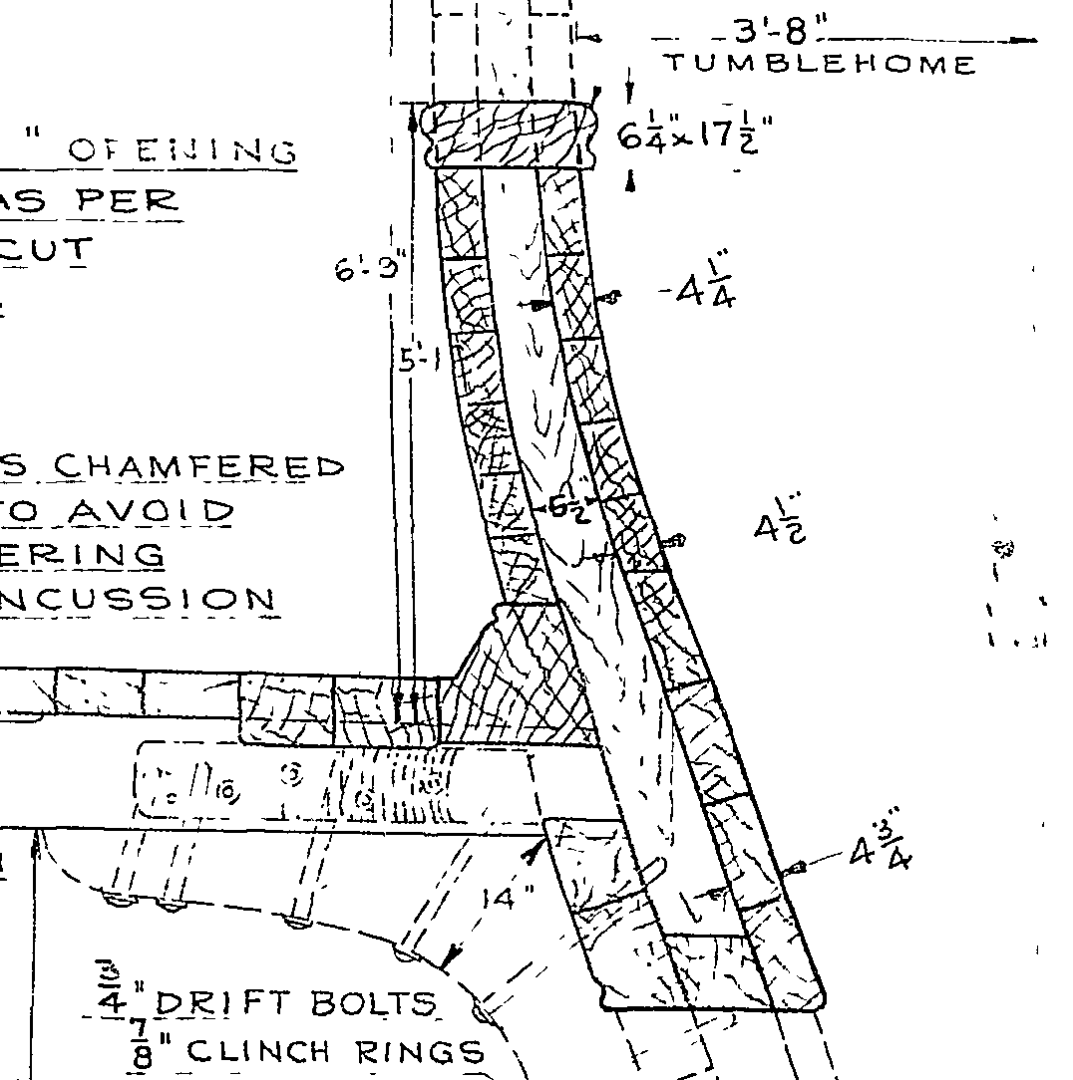
- 233 replies
-
- 1
-

-
- Model Shipways
- constitution
- (and 5 more)
-
I am about the start planking the gunnel(I dont even know if this is the correct term). Can anyone tell me if there should be visible caulking between these planks? I know its a strange question because the original vessel was obviously painted but suggestions would be appreciated. TBE
-
Waterways and planksheer The waterway process was pretty simple. I just cut stock to the size suggested on the plans from a pear stump, then cut away the portion of the waterway that was going to make contact with the bulkhead extension until it sat nice and flush along its length. I then marked the toe of the stock with a 1.5mm strip of wood and the top of the stock with a 2.2mm piece of wood. This created 2 pencil lines, which I could just taper between to create the profile of the waterway. I hope this makes sense, I realise it's a pretty shoddy explanation. The process of shaping the waterway was greatly helped by the application of the hand sanitizer mentioned in a previous post. It really helps with the hand carving component In order to make the curved section I marked out the waterway with a pencil on the plans then cut out this profile and glued it onto a suitable plank after which I cut out the shape on a bandsaw and fine-tuned it on the belt sander. The pieces were then marked using the same technique and installed with the rest of the waterway and steamed for bending to fit correctly. I also made a little modification to my lathe to create a sanding disc that could neaten up the faces of the waterway and make better butt joints. The final step for now was installing the planksheer. It was incredibly difficult to cut 2.38mm square strips on my full sized table saw, but with some sanding I got the stock pretty close. This stock was then cut to length, steamed and shaped to produce the final result which can be seen below. I cannot emphasize enough how important it is to get your bulkheads and extensions properly levelled and aligned. Do the extra work, or you will end up with a wavy planksheer and waterway. I am going to have to fill in some gaps when it comes to the first row of planks, and hopefully this hides the defects. TBE P.S. After writing this post I decided to steam loose the planksheer and waterway where it dipped then force a wedge(a chisel) under the low point and allow the timber to dry. This means that in those places the waterway no longer makes contact with the bulkhead but is at least running straight. Due to the fact that I am using a plywood carrier for the deck, I think I can live with this compromise. I have included a photo below of what this minor modification achieved. I fear only the most OCD amongst you will notice the difference. It is still not perfect, but I can accept it knowing that a lot of this will be hidden by future work, and it is a reasonable price to pay to use this pear wood.
.thumb.jpeg.a9b8eb04cc9b209b31f9fed63dd35430.jpeg)
.thumb.jpeg.dfaf3c0617c3e110af998fe1095bce1c.jpeg)
.thumb.jpeg.de2b68ee5d67e5d4496b931793a3db5c.jpeg)
.thumb.jpeg.7b4ff069e299a5d9ed80cc7d9b372620.jpeg)
.jpeg.fc5dd0da20b1f8ea3457496a1b63eacd.jpeg)
.jpeg.0cadcc295e3563d6b3bdf61a54b29655.jpeg)
.jpeg.d82367583937e46ca07720a0e8cef4d0.jpeg)
.jpeg.6533e2c11379e13eead927499794b48c.jpeg)
- 233 replies
-
- 3
-
-
- Model Shipways
- constitution
- (and 5 more)
-
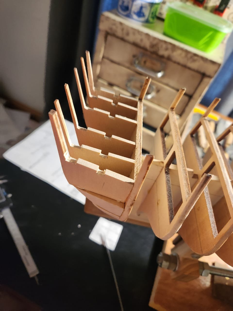
Bowsprit fitting Just a quick post on the bowsprit. In order to get the waterways to fit correctly and be snug up against the bowsprit, I needed to do a temporary fitting of the timber. This item will probably be discarded in the end as there is an old plum tree in my garden with a dead branch that is begging to be turned into masts for this project, but we shall see. To do this one must cut a tenon at 25 degrees into the end of the bowsprit and in my case cut away the knight's head timber support that I made oversize. I had noticed earlier in the build that there was some misalignment in the bulkheads, which meant that I needed to cut away a lot of bulkhead A to allow the bowsprit to lie straight. This also meant that I need to make my tenon slightly narrower so that I could shift the base of the bowsprit slightly to starboard to get everything lined up nicely. The bowsprit in place will appear in my next post. The images below just show that I did this cutting process in essentially 2 steps. TBE
.thumb.jpeg.df7a4e3d222deb4ac76facb896e9bc7a.jpeg)
.thumb.jpeg.019761d53150d556f74f7be02c5b365b.jpeg)
- 233 replies
-
- 2
-
-
- Model Shipways
- constitution
- (and 5 more)
-
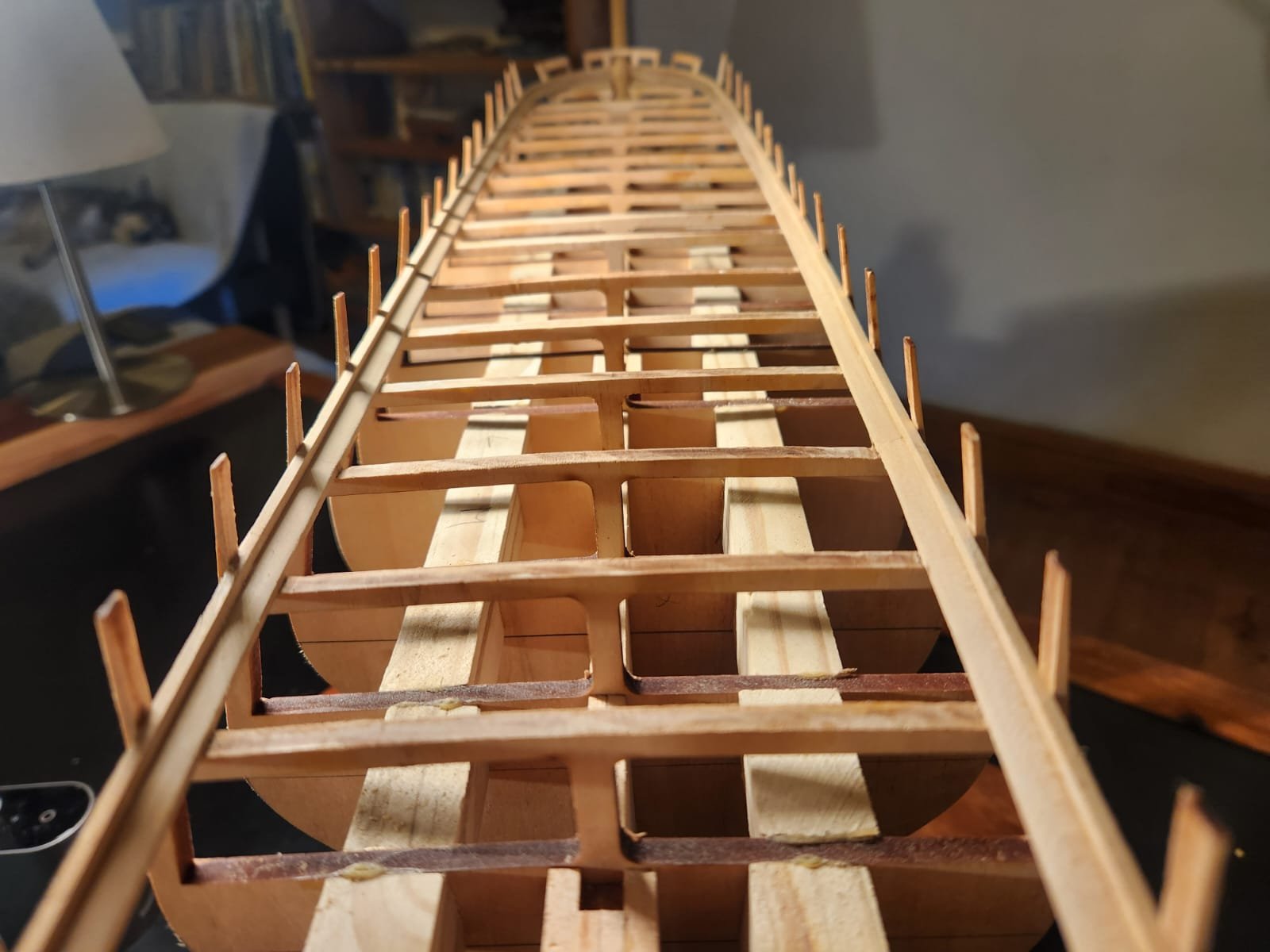
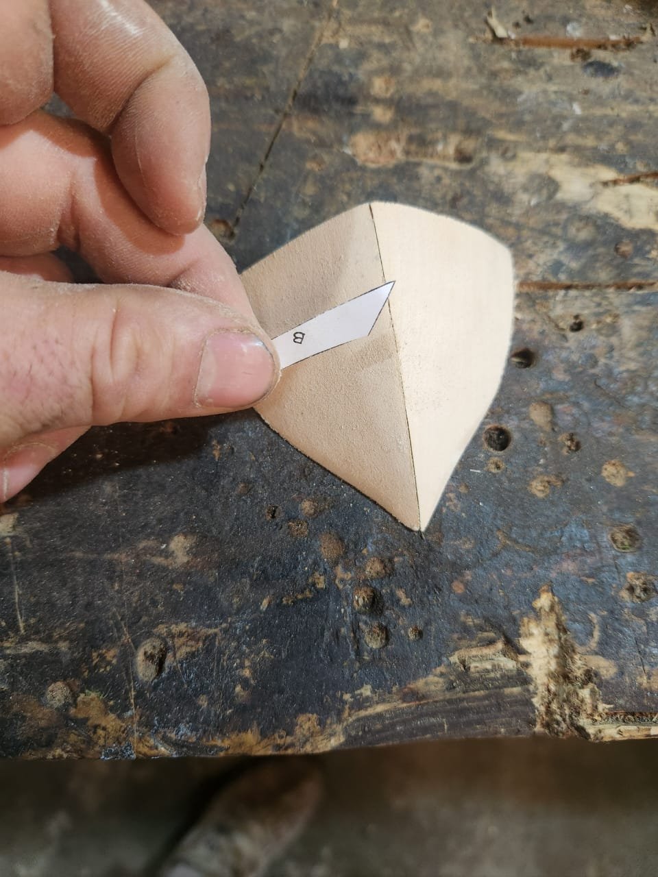
Bow filler blocks Just the usual copying of the plans, gluing them to the blocks with rubber cement and then sanding back to the lines with the belt sander. As with the stern fillers, I used the contour strips provided to help with shaping (see useless photo below). After the basic shape had been formed, I then cut out the profile for the notches in the filler blocks to accommodate the knights heads (apparently this is a misnomer of sorts, but I's sure you all know what I mean. These notches were cut with a combination of cheap chisels from Temu and some sharp number 11 scalpel blades. It did require some fiddling to get everything correctly sized for a nice fit, but I got there in the end. I did pass the block over a flame to burn away some of the messy standing grain that is common with this type of wood after the carving was done. Nothing special with the knights head timbers except that 4 strips that will ultimately edge the bow gun ports were lined with a thin strip of pear wood as I am still hoping to avoid painting this model if possible, this can just be seen in the last photo of this post on the starboard side. I made them up with the usual copying and gluing then sanding method. You will also notice that I left the profile of the upper supports square and did not cut them away. This will later provide support for the spar deck when It gets installed. It is worth noting that this was not entirely correct, and I had to later cut some of these pieces away to allow the bowsprit to fit These parts were then fitted and fared until all was reasonably well positioned for something which will later be hidden under planking. TBE
.thumb.jpeg.6d5699c50f412ac5cfba3f710fd85d12.jpeg)

.thumb.jpeg.bc362993197fbe2a233747bc643a9efb.jpeg)
.jpeg.317c80e950b636f419ea17c7b0af09e2.jpeg)
.thumb.jpeg.937a07495fd3580b1174c58decc12c06.jpeg)
.thumb.jpeg.36672c1b4fd1b419a96d383ce46dd6a2.jpeg)
.thumb.jpeg.646e99c2284f5d96c6072461c865969b.jpeg)
- 233 replies
-
- 2
-
-
- Model Shipways
- constitution
- (and 5 more)
-
Moving on to the transom. Once the stern counter had been installed and the first of the transom pieces held in place, it became obvious that there was an issue with a measurement or two. The transom pieces protruded above the edge of bulkhead "R" this would need to be addressed. As stated earlier, I elected to not make the stern counter thinner, but rather modify the transom pieces to correct the issue. The approach I took was designed to address both the misalignment of the transom and the incorrect angle of the transom. I took an image of the stern gallery and overlaid a protractor onto the image to determine the correct angle for the transom, which turned out to be 70 degrees...see below.... This is a happy coincidence because removing the offending material from the top and bottom of each transom to get them flush with bulkhead "R" translated into a 70 degree transom. It's a bit hard to explain, but hopefully the images of the pencil lines below will show what I did to correct the issue. I then cut away the relevant material above and below the pencil lines, re cut the notches for the cross planking and obviously forgot to take a new photo. To glue these in place, I again copied the plans and stuck the cutout onto the stern counter, then makes the transom positions with a pencil and glued them down while measuring their spacing at multiple locations to ensure they were square. As you can see the extensions are grossly misaligned, I like to think this is mostly the fault of the kit, but I guess I may have played a role in that too. I remedied this by spraying the offending extensions with Propranolol based hand sanitizer and then clamping a slightly flexible sanding block made of wood to the transom to create a nice smooth curve. I was pretty happy with the result. Installing the beams was pretty straight forward. I had however cut the slots slightly wider than needed, so you can faintly see that there are in fact 2 beams in each slot to make up the extra space. Once this was all in, I sanded the faces flat so that everything was nice and flush. The last part of the stern for now was to add filler blocks to the port and starboard sides of the transom. Be careful to not oversize these and allow for the "wings" which are gone behind the stern galleries. I like to do her stern in the 1812 style with 7 windows and a more curved Taff rail. Hopefully this can still be achieved with this layout of transoms and some finagling. Post addition...once the stem and stern were complete, I also added support blocks between the bulkheads cut from a random pine plank I had lying around the workshop. A simple matter of measuring the distance between bulkheads at the false keel and then cutting a matching set of blocks to fit the gap. The result wasn't terribly pretty, but I know that this will all be hidden. It might not have been the worst idea in the world to cut these blocks with great accuracy and install them while installing the bulkheads, and the glue was still wet. In this photo you will also see there are reinforcements on either side of the space for the 3 masts, again nothing fancy, just some off cut wood glued either side of the gap while ensuring they do not protrude above the false keel and interfere with the masts. TBE

.jpg.715ade7b59419bc4c8e48ec5da74ee5a.jpg)
.thumb.jpeg.6b6247f62ce1035af908f4e74fcf1fb6.jpeg)
.thumb.jpeg.974e32c35b3da924306660978d94ce74.jpeg)
.thumb.jpeg.0422b34a74e99ea4f3c2c86448109a7a.jpeg)
.thumb.jpeg.1b96ee1b61eb444b305cb17f40d82f2d.jpeg)
.thumb.jpeg.48bac39160f33df41fbc5f2f7824002b.jpeg)
- 233 replies
-
- 3
-
-
- Model Shipways
- constitution
- (and 5 more)
-
This is all a bit delayed, so I will endeavour to recall what was done when. I took some photos as I went, but it's all a little murky. If anyone has any questions or needs more photos, please let me know. Stern filler blocks and counter. I began with the stern counter. I did this by making a copy of the plans and sticking it to the provided timber of the appropriate size and then sanding back to the cutout, then making the location of the rudder hole and drilling it out. It is mentioned in the build log of @Der Alte Rentner that the plans dimensions for the stern counter create a counter that is slightly thicker than it should be. In my case, this was something like 3.2mm(excuse my French) too thick. I considered slimming down the stern counter to account for this but decided against it as I felt it would have moved the relative orientation of the hole for the rudder in an awkward manner, so I decided to keep the counter the original thickness. This actually worked out fairly well for reasons I will explain later. When fitting the counter, I ensured that the rudder had decent clearance through the hole before final glueing. Next up was to shape and install the stern filler blocks. This was again a process of copying the plans and then glueing the relevant portions onto the correctly sized blocks, then slowly working back to the cutout line with my belt sander. I then used the provided template strips to bring back the shape until it matched the contour lines suggested. Once this had been installed with the help of some elastic bands and a couple of clamps, there was more sanding required to get everything to flow correctly. Unfortunately, I did not take the amount of photos I should have, but I think it's all pretty straight forward. TBE
.thumb.jpeg.d02a71b6c57a546990660070d976a125.jpeg)
.thumb.jpeg.4aa1c2ec374814f17212b0bdd378c7c8.jpeg)
.thumb.jpeg.955efe4d617d5c27ce66d34ffeb640bd.jpeg)
.jpg.b4b4ea8b046210444b4062deb938781b.jpg)
.thumb.jpeg.3f74ef10738af7efcf15e41d21e1068d.jpeg)
- 233 replies
-
- 3
-
-
- Model Shipways
- constitution
- (and 5 more)
-
Hello all A bit of information for those that are interested. I contacted the USS constitution Museum on the advice of JSGerson to enquire about the appearance of the Constitution figure head after the damage she sustained damage during a collision with the President in 1804 and before she had the soon to be headless jackson figurehead installed...This was their response. "After the Hercules figurehead was destroyed, a simple billethead was put in place. This is detailed on pages 116 and 117 of A Most Fortunate Ship by Tyrone G. Martin (Naval Institute Press) and also on his website The Captain's Clerk at this link: https://thecaptainsclerk.com/speaks/book06.html " The above url leads to a great little website full of additional information.... https://thecaptainsclerk.com/ I hope this was of some value to someone out there. TBE
- 233 replies
-
- 1
-
-
- Model Shipways
- constitution
- (and 5 more)
-
Thank you! I will be doing my best to order a suitable blade. All the blades I have significant offset, so they create a very ugly cut. That almost looks like a meat blade, so I may be a bit of a cowboy and see if I have one which will fit on my Rockwell and try that before ordering. TBE
-
Hi Jon My apologies for barging in here, please delete this post if its a bother... Do you have any information on what the rail situation would have been around 1812? While you are rummaging around your vast reserve of knowledge could you please also comment on the open waist represented in the Hull model of 1812? I have been doing some reading and looking at images and now im in a pickle about the subject. Is the vessel meant to have an open waist at this point in its history and if so what does that mean for the waterway and planksheer. If you haven't seen this already you should take a look and this very interesting document. https://books.google.de/books?id=XYUWBpxFZN8C&pg=PR5&dq=uss+constitution+all+sails+up+and+flying&hl=de&ei=hi7NTZDUB4_6sgaqy9m6Cw&sa=X&oi=book_result&ct=result&resnum=1&ved=0CCsQ6AEwAA#v=onepage&q=uss constitution all sails up and flying&f=false TBE
-
This box is honestly incredible. I think I really need to brush up on my work. May I ask what kind of blade you are using for this? I don't want to be that workman that blames his tools but my delta rockwell bandsaw is somewhat long in the tooth, it might be time to get a new saw too or at the very least take a close look at the bearings and setup. On the waterways I think I will do them first as you have done and just be very cautious about the planking. I also took a closer look at the carrier method used by Xken and I see he begins with a cardboard template, That approach will definitely give me more confidence to create an accurate result. Regards TBE
-
Hi Jon Thanks as always for the response. I know this is beside the point, but that is actually quite an attractive drawing. After having taken a look at this and considered the fact that the vessel was in fact built this way as well as the input from Der Alte Rentner I think I will install the waterway first and do my best to get a nice neat join. Does one of your drawings perhaps indicate how the waterway was jointed? I intend to leave the waterway unpainted, so I would like to show that detail if possible. Cheers! TBE
-
Hello all I am still doing some It's and pieces, but the season has begun and finding time to get work on Conny done has been a challenge. I have mostly just been doing research when I have the time. This has led me to the following question… Is there any good reason to do the waterway before the decking? The way I see it, It's going to be a challenge to get all those plank ends and edges to line up flawlessly (even with the carrier I am planning on using.) Why not just deck first and then do the waterway and the gunnel planking after that? Am I missing something, or is there some other bit of structure that will conceal this potentially shoddy edge? Looking at the build log of @Der Alte Rentner and his excellent summary of the decking approaches on the various build logs, I saw that only unegawaya seems to have done his waterways after decking, but I cannot find his log. Please help! TBE
-
Thank you for the suggestion. I am definitely going to look at this as an option. I am really struggling to get decent planking using my methods and your suggestion might just be the answer. Kind regards Haiko
-
Music to my ears Johnny. You made a very good point. I'll leave those frames as is and maybe just be a little more energetic with my char removal. Thank! TBE
-
Hi Everyone I am busy building the Model Shipways USS constitution. The hull planking material provided is basswood and the plans are for single planking with the provided timber. As I would like to leave my hull unplated and unpainted I plan to double plank the hull. I want to do the first planking with the provided timber to get a bit of hull planking practice in and then plank over this with pear wood planks of 1.5mm thickness. I have already adjusted the rabbet and bearding line making them 1.5mm thicker. What I am wondering is if i have to make any changes to the suggested faring indicated on the drawings? does it make sense to take an additional 1.5mm off each of the frames or can I get away without doing that. If there are any other things i should be thinking about when adding this additional layer of planking which the kit is not designed for. Thanks! TBE
-
As I am about to move onto the faring, can anyone perhaps tell me if I need to remove additional material to account for the fact that I am adding an extra layer of 1.5mm planking. I can't quite decide if it makes sense to add another 1,5mm of faring on the bulkheads or if the additional width on the bearding like and rabbet will be sufficient
-
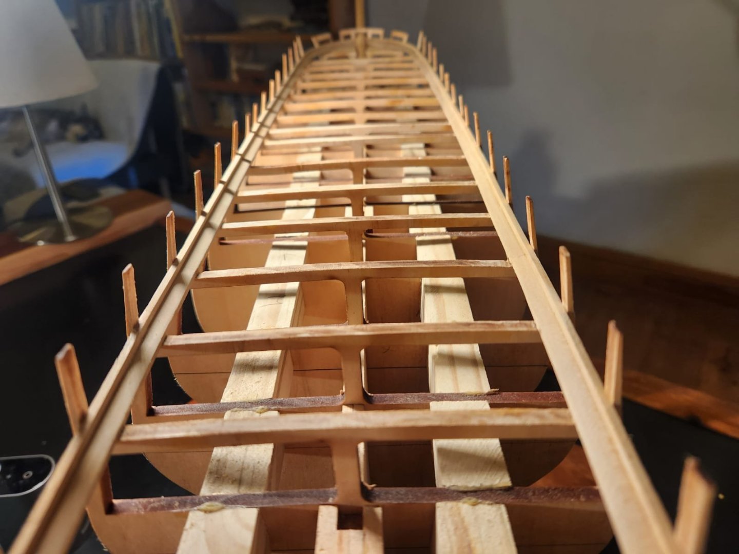
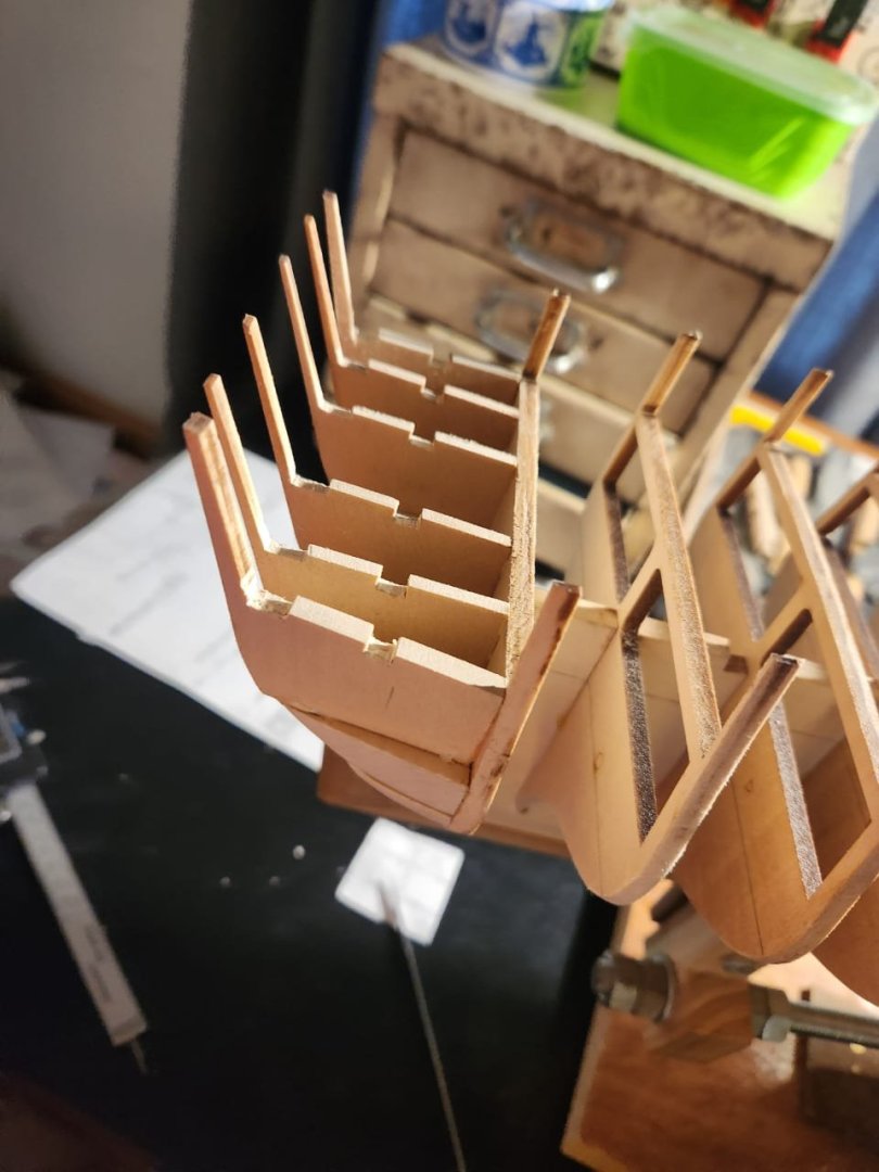
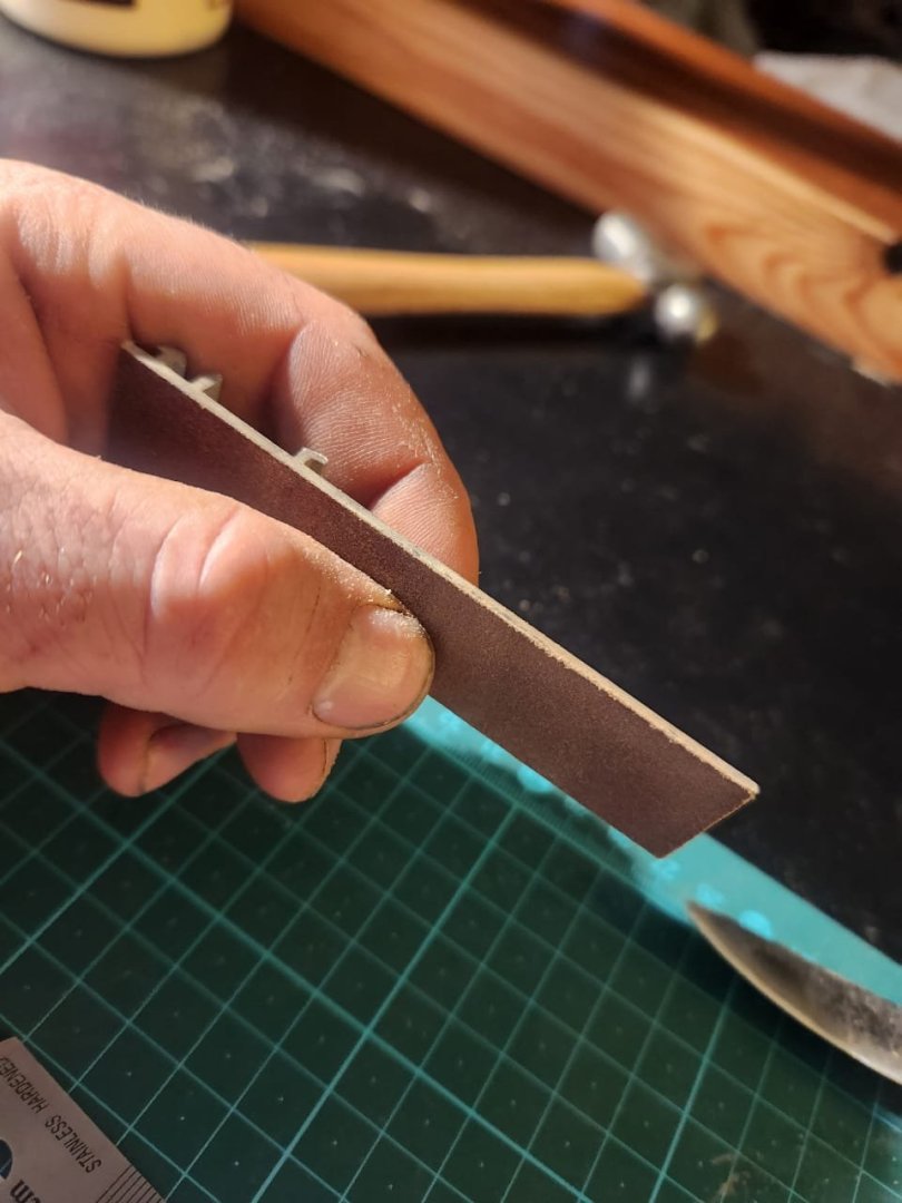
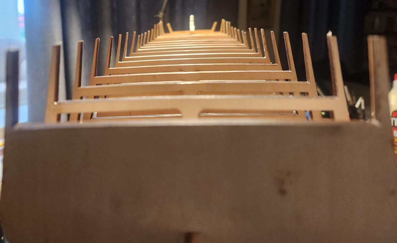
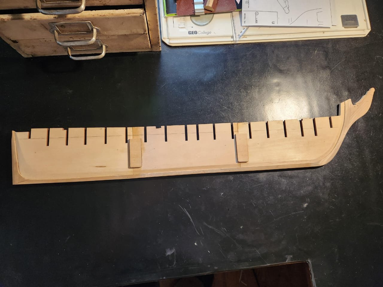
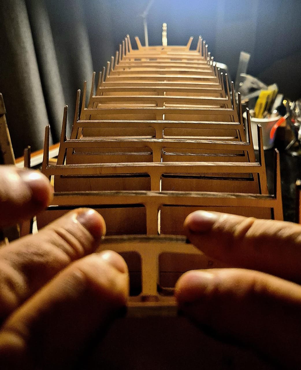
Again, not a huge amount to share.. I transferred the reference line from the drawings provided to the bulkheads. I did this by extending the reference line with pencil, placing the bulkhead over the drawing and parking the edges of the line onto the part, and then joining those 2 marks. The plans and the parts match up pretty poorly, so I elected to use the cavities above the gun deck as my alignment reference. I then sanded out the slot in each bulkhead with a small sanding tool made by gluing sand paper to a piece of aluminium that as floating around my workshop. Next I inserted the bulkheads into the false keel, I found a certain amount of additional sanding was required to get the parts to fit and to get the reference marks to align between the bulkheads and the false keel. The photo below shows what the bulkheads looked like with only the reference lines matched up and no additional work done on the bulkheads. It is not hugely obvious, but the alignment is pretty poor. Casting a careful eye over the "deck beams" shows that they are not all level at all. I corrected this with the following 5 different approaches, depending on the specific bulkhead in question. By looking down the length of the vessel and eyeballing the heights of the beams I adjusted as follows until they were reasonably ell aligned(I did not go for complete perfection as I am using a plywood carrier for the deck, but I did get it fairly close) 1. rotated the bulkhead, changing which side faced forward or aft, this actually helped a lot 2. removed material from the bulkhead with a combination of a sharp knife and sandpaper 3. added some material to the top of the bulkhead in the form of a strip cut from a sheet of 0.5mm plywood. 4. tapped some of the bulkheads so that they came up slightly from their original alignment with the reference lines to align better at the deck level. 5. Some bulkheads were fine as is and required no adjustment. The slight but pretty essential correction can be seen below. I will now move onto removing char and rough faring the bulkheads before gluing them in place TBE
.jpg.53b404aadc0f83be404888df50b67d0a.jpg)
.jpg.1bea87d6fd0db722233d47323df493cf.jpg)

- 233 replies
-
- 2
-
-
- Model Shipways
- constitution
- (and 5 more)
-
I'll add this to the list. If you look at my constitution build one of my most recent posts is of a carving knife I banged together froma ball bearing and some of this pear wood with linseed oil, this did make me think that adding some more natural oils to the tests would be a good idea.
-
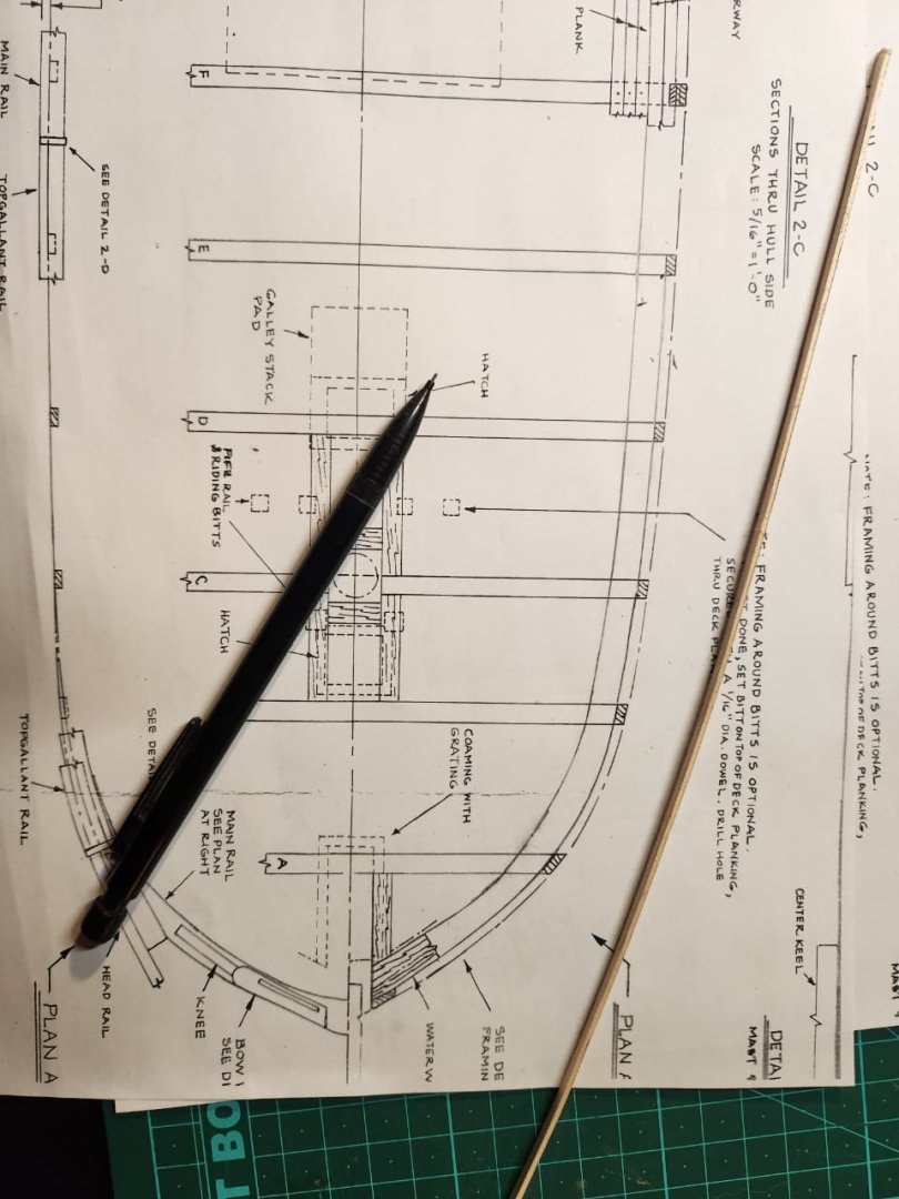
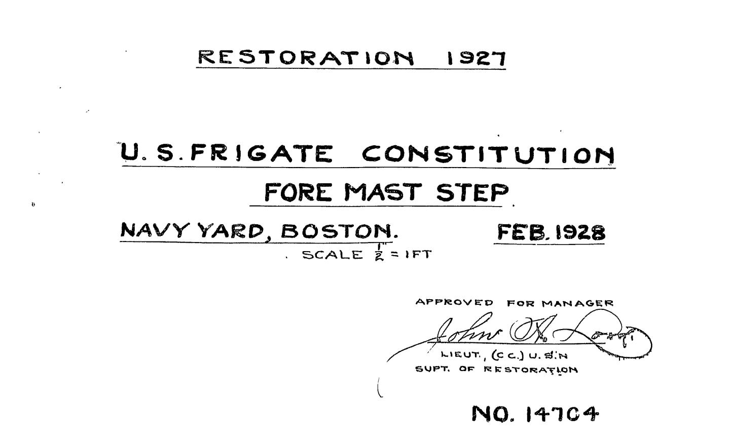
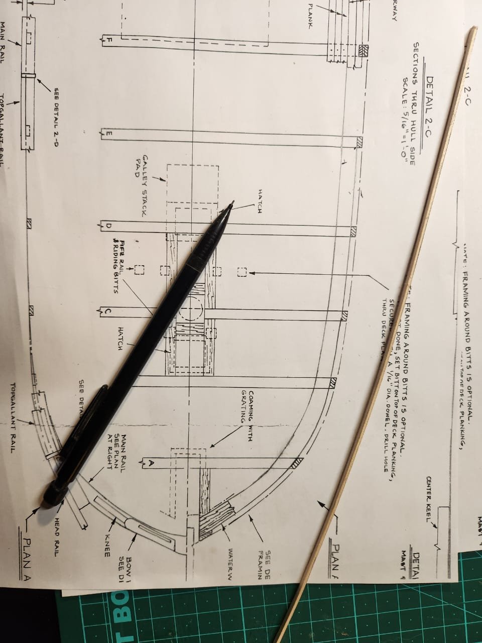
Good Evening Thukydides Thank you for your interest and input. I got the drawings from @JSGerson who tells me that the plans come from the US Naval archives. I believe he purchased a CD which was originally available from the same website which you reference above. Apparently it contains significantly more drawings than what one sees listed now. If one looks in the bottom right-hand corner of the uncropped image (can be seen in post #42 of this log) the number "14705" is listed if you go to the link you shared you can see a drawing of the fore mast step with the reference number 14704 written in the same format as on the drawing I worked from, this makes me feel that the plan is probably as reliable as one can hope for such things. I really appreciate your work and interest. I hope that you jump in if you ever see me doing something stupid. I am very inexperienced, and I am always in search of help. Haiko
- 233 replies
-
- 2
-
-
- Model Shipways
- constitution
- (and 5 more)
-
Thank you Wawona I must say i do quite like it. The steel is rock hard and shaving sharp. I am looking forward to learning how to use it.
-
Hi Marcus Thanks again for your information. I totally agree with you on the early years of the constitution, I would like to get as close to that as possible. I have emailed the constitution museum to ask them for a description of how the cutwater looked in 1804, hopefully they have an answer for me. I tried to follow the link to your German website, but it says that I don't have permission to view these images. Must I sign up for the website to access them? Please share as much as you can, I really hope to be as true as possible to the original design as possible. Maybe you will approve Haiko
- 233 replies
-
- 1
-
-
- Model Shipways
- constitution
- (and 5 more)
-
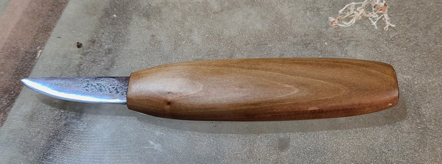
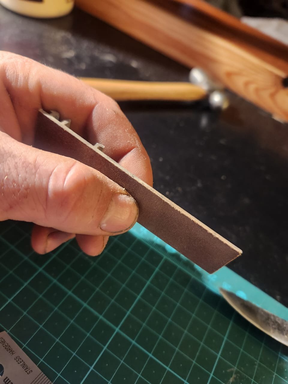
Little side project. I needed a carving knife that I could comfortably drag toward me for rough shaping parts. I forged this from the outer race of a ball bearing and a chunk of pear stump offcut coated in linseed oil
- 233 replies
-
- 2
-
-
- Model Shipways
- constitution
- (and 5 more)
-
This is a great idea! I just emailed them. I will report back on what they say. Apparently it takes up to 8 weeks for an answer, but hopefully that Is not the case. I am very much realising that you are right about now being the time for modifications. I think this model will be decidedly unforgiving in the future. Thanks Haiko
- 233 replies
-
- 1
-
-
- Model Shipways
- constitution
- (and 5 more)
-
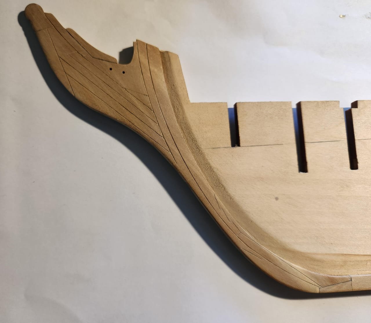
Last Keel post for now. After making copies of the plan and transferring the closest possible layout onto the plans, I made copies, scanned and mirrored the image and reprinted the set at the right size. I then cut out the layout and glued the template onto the stem using rubber glue as suggested by JSGerson. I then Cut along the relevant lines with a scalpel, removed the paper and deepened the grooves with a micro chisel. After this I filled in the lines with a lead pencil, cleaned the wood up with an eraser then sanded and cleaned the grooves. The final step was to cut away the portions of the stem indicated in my previous post and replace this area with a new cutout of wood to match the plans I have access to. I am not totally happy with the outcome, but a fair section of the stem will end up being painted black with the design I am going for, so hopefully it will hide the defects I don't like. I also etched and applied pencil to the other joints in the keel, which somewhat improved their appearance, too.
.thumb.jpeg.04a3aa2895f834a27e5eb4c834499471.jpeg)


- 233 replies
-
- 5
-
-
- Model Shipways
- constitution
- (and 5 more)

.jpeg.8308e3da6c7bb7d11b632cf32cec3e94.jpeg)
.jpeg.9707d17de5eefb43e1a852e8b64f4b4c.jpeg)
.jpeg.481f57cc3d1e41fba2e1a229373fd797.jpeg)
.jpeg.b1ed0846188a7d7b5688818cd037c7c1.jpeg)
.jpeg.e5fde0a6825370dead98c7bcfcae3b26.jpeg)
.jpeg.28617fbff30cc4f30a8e8266592f759c.jpeg)
.jpeg.385f3ad14391744c8c28f67f28760703.jpeg)
.jpeg.65f94257a88e6db0dd9db8eb67f2b61a.jpeg)
.jpeg.6e6f71289b394fc599dca38934516829.jpeg)
.jpeg.aa1f4dae5b5bdd6beac9c6f713d9b310.jpeg)
.jpeg.ddf43c8fe519089c1184b02322405078.jpeg)
.jpeg.9cee6c701303282256fde479711bc60f.jpeg)
.jpeg.c6a9021f2cb8ab6792b46629d7d09aa9.jpeg)
.jpeg.06e1f1aa67ac8faf4fecaf6f953c99a1.jpeg)
.jpeg.260a23f3f8c1189477df10091c83d64b.jpeg)
.jpeg.69f4d1203f8674450b1b3d409a1f37b2.jpeg)
.jpeg.20ae04299aad389e070a0bb9615f9e9d.jpeg)
.jpeg.04cf0e9a2d9e2ebcd9b2fa61f947f10d.jpeg)
.jpeg.82a05a303f807d4e46c7e72f5900e7ea.jpeg)
.jpeg.eeb4872f51be05d7517984baccdf26ef.jpeg)


.jpeg.e2236600f94f94124c675d979d8aac9a.jpeg)