tmj
-
Posts
730 -
Joined
-
Last visited
Content Type
Profiles
Forums
Gallery
Events
Everything posted by tmj
-

Shot Garlands
tmj replied to tmj's topic in Discussion for a Ship's Deck Furniture, Guns, boats and other Fittings
Would the open bottoms of those pockets be for corrosion control/ water drainage, or was it just easier to make the garland's in such a manner? -
Shot Garlands
tmj replied to tmj's topic in Discussion for a Ship's Deck Furniture, Guns, boats and other Fittings
Thanks Gary. I can see far more than just 'scalloping' going on here! This is nothing that I had envisioned, but I also really like what it shows! "Hmmm?" I may need to leave a few shot out of the garlands in order to display a construction method such as this! Very good, "Thank you!" -
Did 18th century British shot garlands (first rate) actually have bowl shaped pockets carved into them, to accept the shot, or would they have been made as more simple 'troughs' to hold that shot, perhaps with a bit of padding to keep the loose shot from rolling around? I can see pro's and also con's to both scenarios from both a 'construction' point of view as well as functionality. Working with a mass-produced kit makes it difficult to determine what is actually real and what is complete fantasy!
-
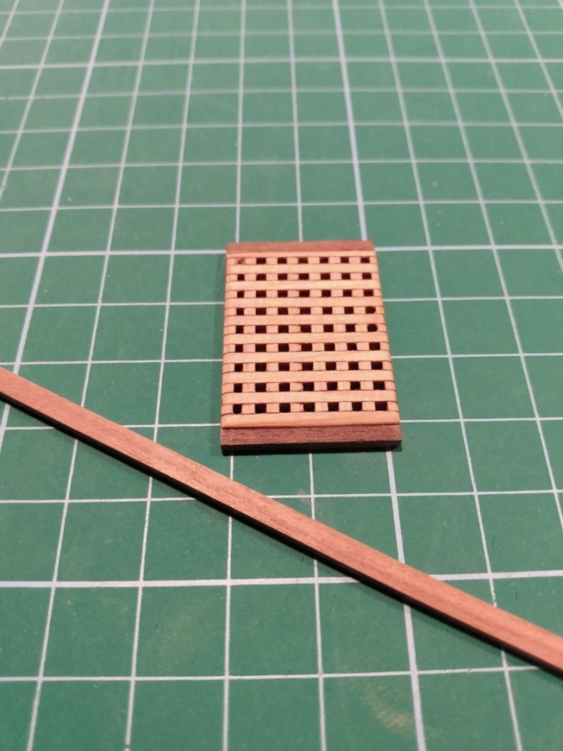
I was able to steal a bit more time today, while supper is cooking. I've sanded the edges of the gun deck straight and true... and also trimmed out the fore and aft edges of the grating. The long piece of timber is going to become the shot garlands for holding the cannon balls. I need to carve pockets into those pieces, using a 'ball mill routing bit', on my drill-press, to hold the cannon balls before I glue those shot garlands to the port and starboard sides of my grating. I could glue the garlands on now, but if I get off of proper placement with the 'pockets', and it looks bad, I'd have to cut the garlands away and start over. That's too much work. I'm going to drill my shot garlands first. If I'm happy with the pockets for the cannon balls, 'THEN' I'll glue the shot garlands to the sides of the grating and prepare to install the grating onto the deck.
-
New grating material arrived. It's been cut to size, glued together and sanded. Next up will be preparing the deck, gluing the grating down and trimming it out on the deck. I was hoping to get everything done today but ran out of time. "To be continued."
-
Grating arrived, but it was the wrong grating. I had to re-order the proper sized stuff. I've been waiting, again! No additional work has been done other than a bit of staining and touchup work. New grating is now 'out for delivery'. Fingers are crossed in it being the proper size this time!
-
CNC Desktop Router Reviews
tmj replied to tmj's topic in CAD and 3D Modelling/Drafting Plans with Software
I'll be watching this. The only reason that I am starting off with Autocad is because that's the only CAD software I've ever used. I've also never used CAD/CAM for 3D and wood, only 2D and metal. There could very well be better choices out there. -
CNC Desktop Router Reviews
tmj replied to tmj's topic in CAD and 3D Modelling/Drafting Plans with Software
500W 4540 sized Router, assorted tooling (including a surfacing bit) and a preliminary dust control system. It's all here now! I believe that I finally found the Fusion 360 info that I was desperately seeking... without having to learn things about Fusion 360 that I do not currently need to learn. I only want to use Fusion 360 as a 'nesting' program and to set the tool paths and generate G-code for my 3D work that was previously developed in AutoCad. Fingers are crossed... "I'm going in now!"
-
CNC Desktop Router Reviews
tmj replied to tmj's topic in CAD and 3D Modelling/Drafting Plans with Software
What is 'SU pro'? More spelling, please. What does 'SU' stand for? -
CNC Desktop Router Reviews
tmj replied to tmj's topic in CAD and 3D Modelling/Drafting Plans with Software
Yes, there is a Fusion 360 'Personal Use' license that is available for free. Go to Autodesk.com -
CNC Desktop Router Reviews
tmj replied to tmj's topic in CAD and 3D Modelling/Drafting Plans with Software
Many thanks, Gregory! I'll definitely look him up! Kevin, I've been using Acad since release 10 for DOS. Due to this I thought it would be a very simple transition, but I was wrong. The commands appear to be the same, but the way in which they are being used in Fusion seem to be of a totally different animal, at least for now. I poked around in it for about an hour today, my first exposure to Fusion, and I finally had to shut it down before my head exploded! Way different than what I expected! I'll definitely look into 'your' link as well. I'll eventually get the hang of it; it's just going to take a lot more time than I thought it would... -
CNC Desktop Router Reviews
tmj replied to tmj's topic in CAD and 3D Modelling/Drafting Plans with Software
Yes, Fusion will allow me to save my files in the STL file format. I'll just need to learn enough about Fusion 360 to import and save my 3D Acad files as such. This will help me get started faster while I go about the process of learning Fusion 360 in more depth, I hope! 😶 -
CNC Desktop Router Reviews
tmj replied to tmj's topic in CAD and 3D Modelling/Drafting Plans with Software
Lots of 'heads-ups' and nice to know info shown in your thread. Thanks for sharing! I can now only wonder what assembly/operational difficulties will come with 'my' new machine. Ron, do you use Fusion 360? I just got Fusion and currently see a steep learning curve in my near future. While I can model quite well, and fast using Autocad, Fusion 360 is looking totally different to me. Can I do my 3D modeling in Acad and then just import those completed files into Fusion to create the G-code and toolpaths? Tom... -
CNC Desktop Router Reviews
tmj replied to tmj's topic in CAD and 3D Modelling/Drafting Plans with Software
Thanks Ron! I'll tune into the thread! -
CNC Desktop Router Reviews
tmj replied to tmj's topic in CAD and 3D Modelling/Drafting Plans with Software
Thanks Ron. No laser module, just a rotary router. I take all of my laser projects to work. -
CNC Desktop Router Reviews
tmj replied to tmj's topic in CAD and 3D Modelling/Drafting Plans with Software
The search is over. I decided to drop the 4th axis idea, for now, and purchased a different 500W 4540 3 axis system, not Genmitsu. Amazon will be delivering it Monday. -
Allan, Could you possibly highlight the unnecessary pieces and email me with your visual representation of what pieces I need to eliminate?
-
'Hancock' Stem and Stern Design 'Take Two'. "Am I getting closer, now?"
.thumb.jpeg.61eaf15e5d7bc9fe5e4d795609333de1.jpeg)
-
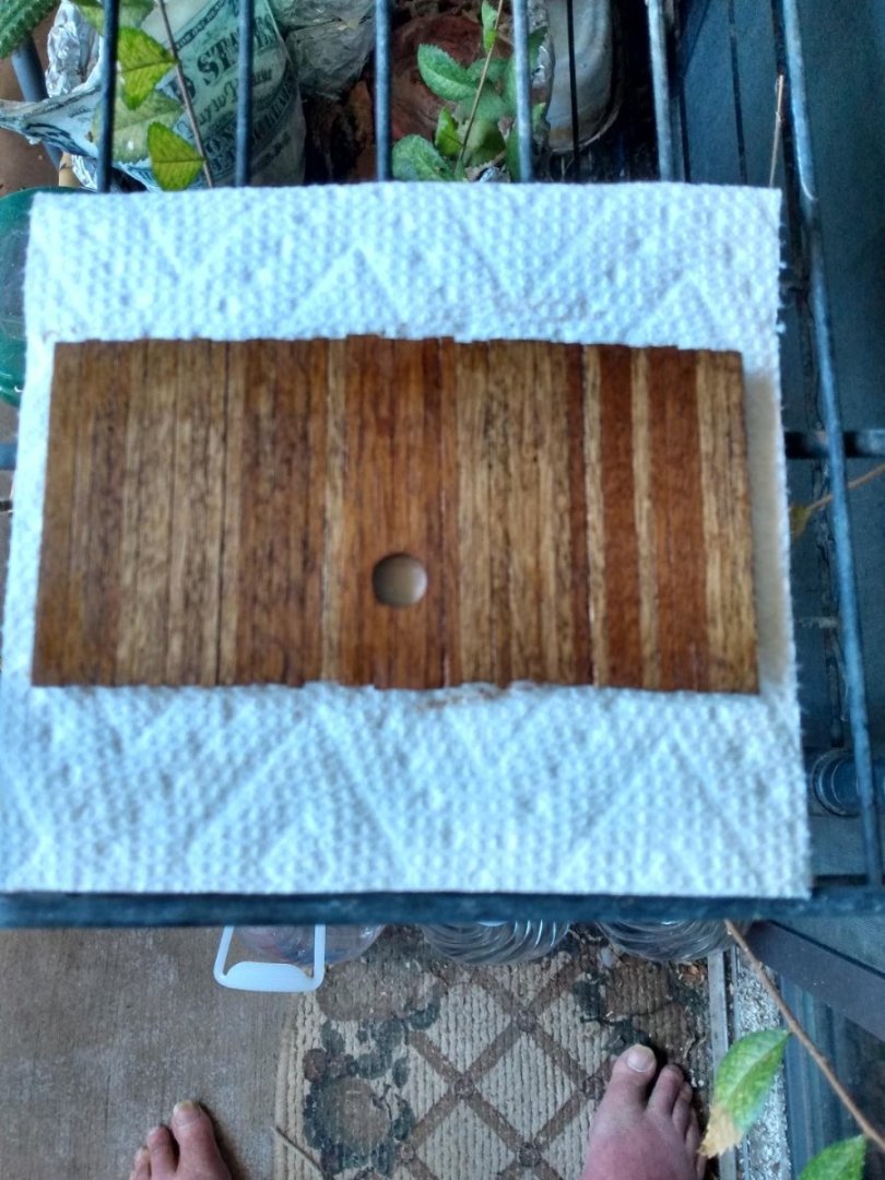
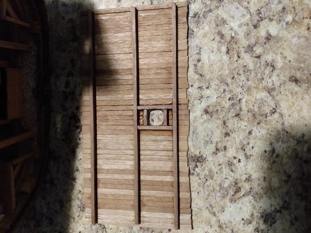
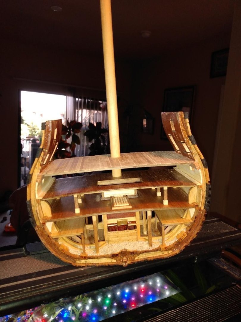
I ran into a problem, today, after applying some stain to my middle gun deck. I don't like the look of this, but I'm going to go with it just the same. I don't want to rebuild this deck. Hopefully the different shades of wood (all the same wood) will not be too terribly noticeable once the model is completed, the deck is populated with 'Gun Deck Stuff', grating, and the deck also becomes somewhat 'shaded' and shadowed by the upper decks that are yet to be built and installed. I'll need to pay closer attention to what the wood looks like while I'm laying the planks atop the remaining upper decks. Note to Self... always stagger dark and light planks to ensure that this does not ever happen again! Second Note to Self... try to keep toes and unclipped nails out of future pictures! 😐
-
I'm looking at a 'Genmitsu' CNC router 4040 pro (Amazon), with the fourth axis accessory, for a home 'desktop' sized unit. I have a router at work, but I'd rather work on my hobby projects at home, at my leisure, and not have to bother with going to my place of work to use their 'HUGE' CNC router for small sized projects. Not very convenient. Does anyone have any experience using this specific Genmitsu 4040 Pro router? Suggestions for other routers would also be appreciated provided you have firsthand experience using the model that you recommend. 4th axis is also a huge selling point for me.
-
I was hoping to take care of the grating on my middle gun deck this weekend, but that's not going to happen. The grating material that came with the kit has proven to be insufficient, in quantity, to properly make the grating size needed for the middle gun deck. I just ordered some grating material from Model Expo, but it won't be here until next week. I might just continue planking the interior of the hull and work up towards the upper gun deck while I wait. I might even just put this build on hold, until the grating arrives, and work on another model in the meantime.
-
Thanks guys, this helps! What if I were to use a pattern similar to Allan's 74 Gun Ship circa 1798 example for the stern, and David's pattern on page #137 of his book (vol 1) for the stem? Would those two separate designs be acceptable and also likely for a ship the size of 'Hancock' and also the era? Sorry guys, I'm not showing the image from David's book. Copyrighted material and respect for David.
-
Not being an 18th century ship builder, nor a forestry expert, this initial draft represents my first attempt at designing the stem and stern sections of a circa 1776-1777 Continental Frigate without having a whole lot of usable historical engineering data available. This design is currently nothing but a ‘concept’ and a subjective work in progress. Every time I look at my drawing, I discover something that just doesn’t look correct, at least not correct from a ‘modern day’ engineering perspective... and then I quickly modify the drawing. I probably should not do this as methods of engineering that are used today are nothing like they once were 247 years ago. I’m just simply doing my best to try and design something that would be structurally sound and actually feasible via the readily available sizes and shapes of wood, ease of layered assembly construction techniques and the stable ‘locking’ of timber components together to prevent shifting wear and also reduce the potential for undesirable stresses being placed upon certain components while under heavy loads. “That was a ‘mouthful’ of ‘blurbage’, but you know what I’m trying to say!” The hull of this ship is based upon Harold Hahn's plans for the Continental Frigate 'Hancock' 1777. His model was rather small, so I doubt that details of the stem and the stern framing would be easily seen. That's probably why his stem and stern pieces are basically nothing but a blank canvas on his plans. It makes sense. Why put a lot of work into something that will not be seen anyway? I'm scaling the model up and believe that these details will now be visible to those who want to peek between the frames. I'll never get the actual framing of the stem and stern 100% correct, so I just need to make it look reasonable for 'possible construction methods' of the time, artistic licensing included. Let me know what you think, what should be changed, etc. Please note that the keel is not ready to be reviewed yet. It's currently just there to keep the Stem and the Stern sections from falling off of my computer screen!🙂
.thumb.jpeg.58079a7c45c2a18b3d9ae0d05a6ba87f.jpeg)
-
Has anyone ever experienced issues with wood swelling and cracking via changes in weather and humidity, over time, where lots of 'deadwood', etc. is used in the stem and stern of your models? Expansion, contraction and eventual cracking. If so, how do you counter this problem and prevent it from happening?
-
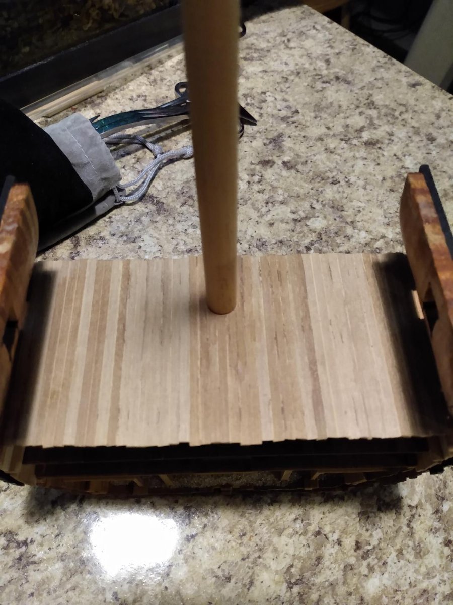
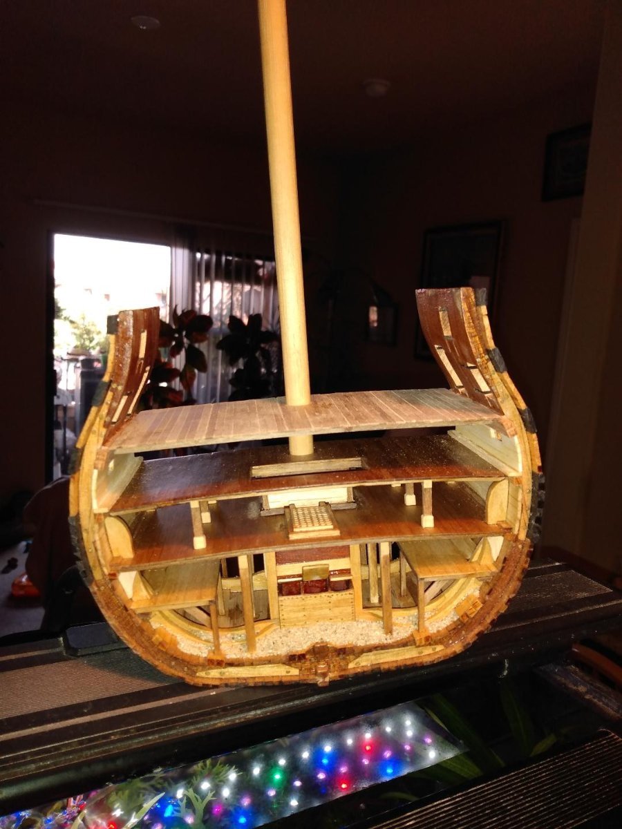
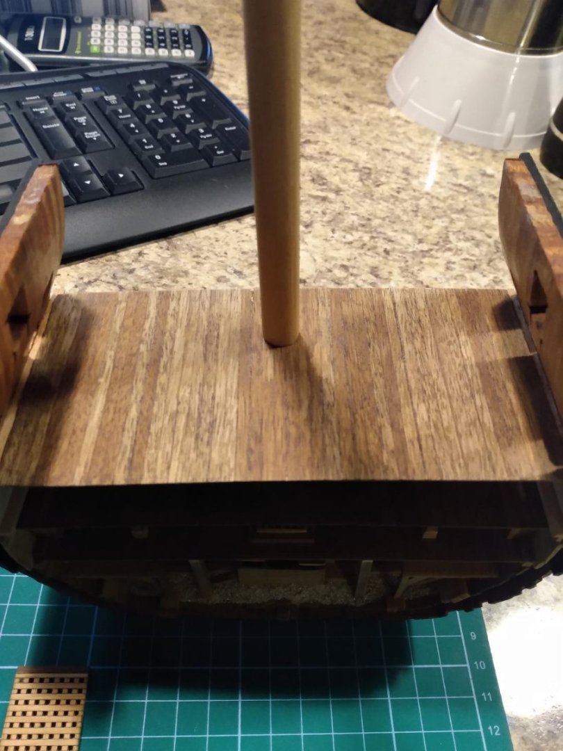
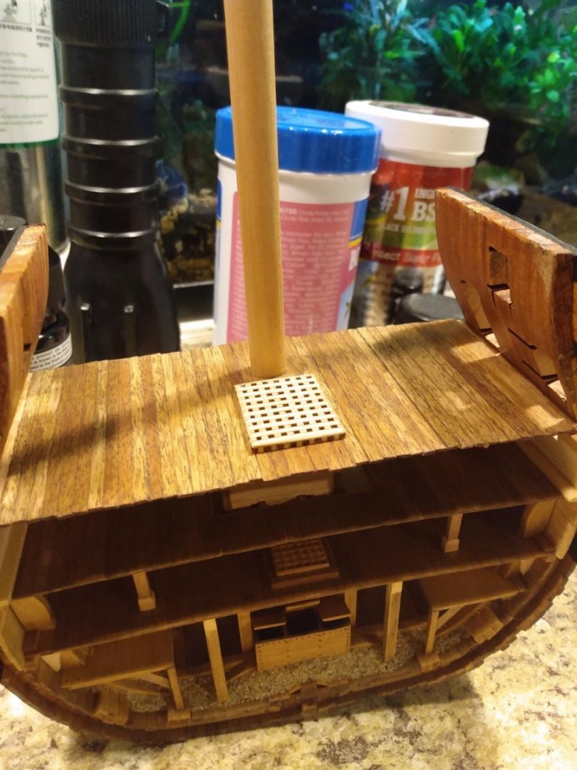
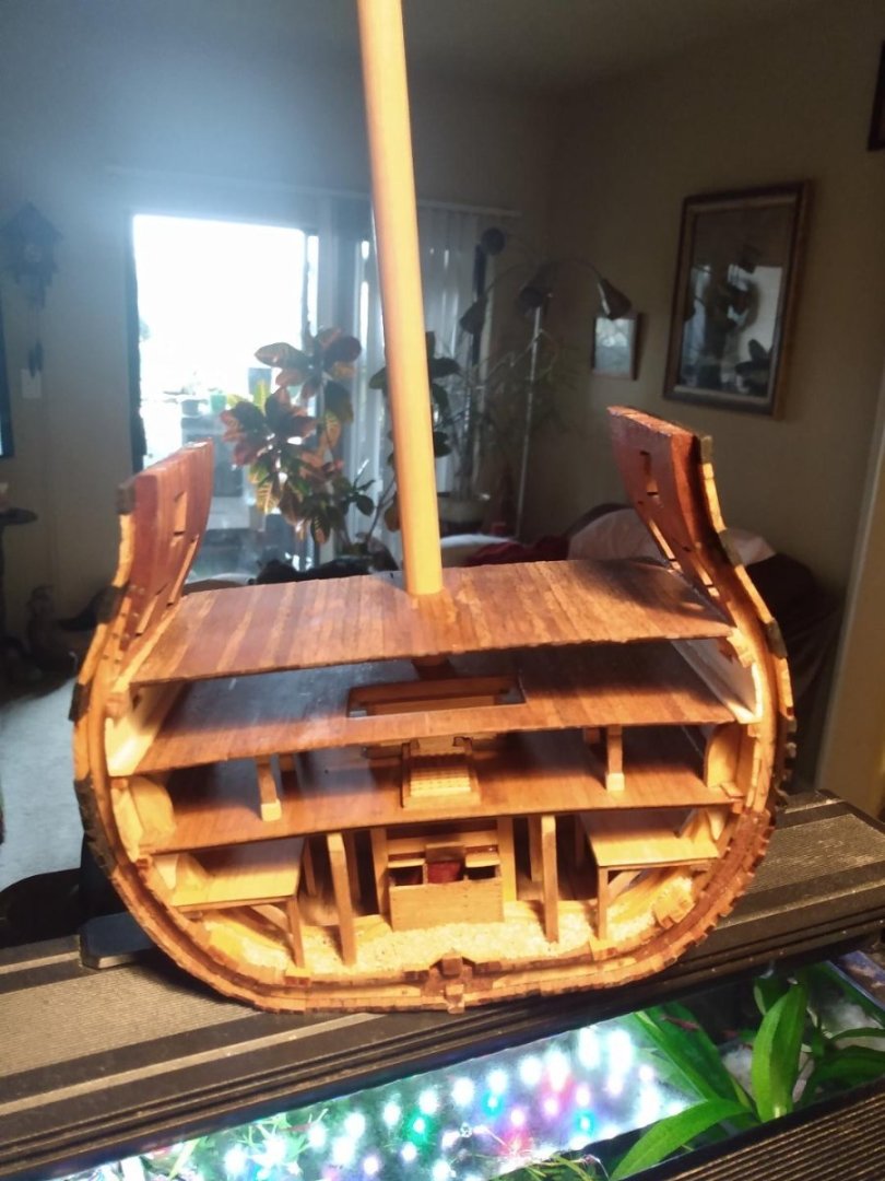
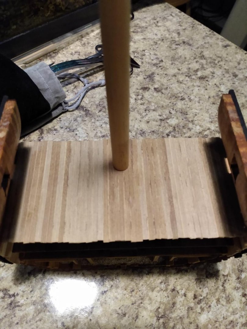
The framed in area was first CA glued really well, for strength before drilling. I also put masking tape on the top side of the deck to prevent splintering when the forstner bit came through the planking. After drilling, I rolled up some 400 grit sandpaper to work the hole until the mast fit "Jussst Right!" "Nice snug fit!" Everything perfectly centered and canted!


.jpeg.04d03f090d3226262f444a9d47ab7a14.jpeg)
.jpeg.07af08256c8e25179535992c0d7f00b4.jpeg)