tmj
-
Posts
730 -
Joined
-
Last visited
Content Type
Profiles
Forums
Gallery
Events
Everything posted by tmj
-

Gunboat Philadelphia 1776 by tmj
tmj replied to tmj's topic in - Build logs for subjects built 1751 - 1800
Nothing much to see right now. This is just me being bored and wishing that I could do some work on the Philidelphia's bottom. I was wanting to lay out the outline shape of the bottom, for cutting, of which I could do, however. I was 'also' wanting to start laying out the locations of the numerous flooring timbers on the top side of the bottom, but I need to do some sanding first. I can't sand right now. The Tung Oil is still a bit too tacky and I don't want to risk sanding dust getting stuck to uncured Oil inside my caulking channels. That would ruin the effect. High humidity is the culprit, and it is seriously hampering the Tung Oil curing process! Tung oil hates high humidity but 'loves' a lot of air circulation. I've moved the slow curing bottom into a less humid environment and also put a computer fan on it to move a lot more air over its surface. If the curing still seems 'stalled', I'll put it into my oven with the oven light on (good for 90 degrees in temp) and add the fan too. That's how I cure/dry Biltong. I hang it in the oven with the light on, the fan blowing, and the oven door cracked open to let moisture escape. That works well for drying Biltong... it should work well for curing Tung Oil too, maybe. Not sure. All I know is that if this bottom has not satisfactorily cured, come noon tomorrow, I'm turning it into Biltong!
-
Gunboat Philadelphia 1776 by tmj
tmj replied to tmj's topic in - Build logs for subjects built 1751 - 1800
Greetings Mike! I'm building this in 1:24 scale. I'm using Cherry for the bottom and for what few planks that I'll add to the sides. A lot of my build will be open, somewhat Navy-Board style, so there will be a 'LOT' of air and light moving through the insides of this model. As for the internal flooring timbers, frames, etc., they will be easily seen. I'll be using lighter colored Boxwood for those interior components to achieve a nice contrast in colors within the darker hull and atop the bottom planking. I'll likely stain the boxwood components to tone them down just a wee bit, still leaving them brighter than the darker cherry exterior. I've so far only purchased wood for the hull and interior framing. What I use for the decking, etc. has yet to be decided. I'll choose the rest of the woods as I go, depending on how things actually look as the build progresses. I don't like paint; I like to choose woods whose colors closely resemble the finished colors and tones that I desire in the finished product. -
Gunboat Philadelphia 1776 by tmj
tmj replied to tmj's topic in - Build logs for subjects built 1751 - 1800
Thanks Cisco! I still have a bit to go before successfully achieving the full effect. I'm working on it. Waiting for pure Tung Oil to cure is a real pain, but so far, it's the best medium I've found for doing this sort of thing. The oil is drying a bit slower than I hoped, likely due to high humidity here. I'll be able to move on once the oil finally cures. Are 'you' by chance building a Philidelphia model yourself? -
Hello Max, welcome aboard. You will find a wealth of information on this forum. Feel free to ask away. Are you sure that you truly want to pursue a model, such as this, for your first model? That will definitely prove to be a 'very bold endeavor'! Best of luck to you!
-
Gunboat Philadelphia 1776 by tmj
tmj replied to tmj's topic in - Build logs for subjects built 1751 - 1800
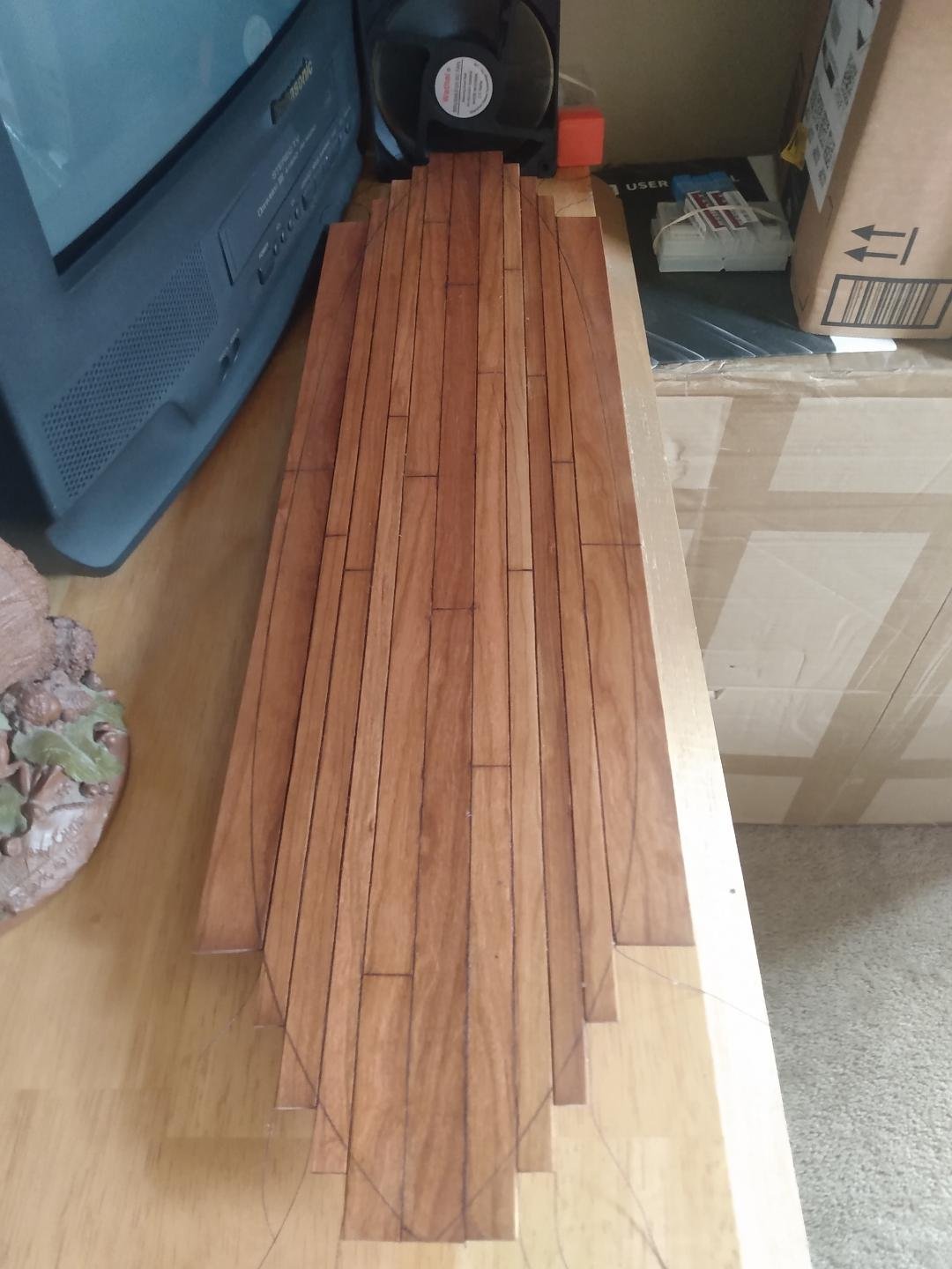
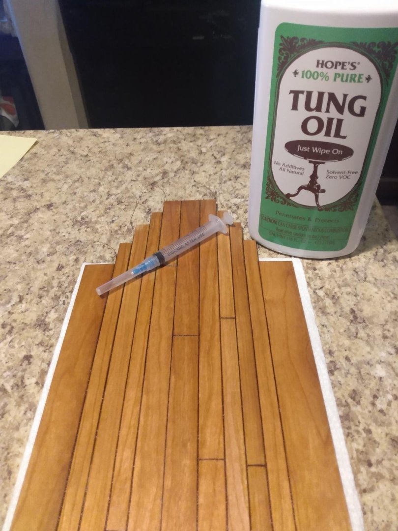
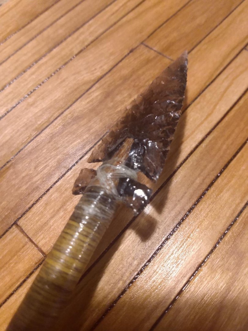
It's going to be a slow weekend. I'm waiting on Tung Oil to dry which is a bit slow. What I've done is to put a light coat of Tung Oil on the entire bottom to somewhat seal the wood. I've also filled the caulked seams with a thick layer of Tung Oil to represent a 'pitch' cap/layer atop the simulated oakum. I chose Tung Oil because it has a rich, dark, somewhat copperish color to it if applied thick. The thick Tung Oil atop my black thread Oakum should produce a nice looking and well blended color for my caulking seams. Once the thick tunnels filled with Tung Oil have finally cured within my caulking seams, I'll sand the bottom to lighten up the color of the planks and strakes. This should produce a very nice contrast between the lighter colored surface of my planks and the darker, multi-colored caulking seams. You'll also note how covering the 'Tuff-Cord' Oakum with Tung Oil 'pitch' produces a 'rippled' surface within the caulking seams. This is another effect that I am desiring. I've made pitch before, back in my flintknapping and primitive archery days. It's hard to get hot, tacky and gummy pitch smoothed out to a slick, smooth finish. I'm sure that shipbuilders once had the same problem. This is where the 'Tuff-Cord' comes in handy. The Tung Oil will soak in and take on the same surface shape of the cord. After a couple of thick applications, the ripples will smooth out a little, but not entirely. The caulking channels will always have a slight ripple effect to them, unlike the end result should plain glue be used as a filler. Yes, it's a lot of extra work, but I feel as though the end result/effect will be well worth the additional effort. Here's the bottom... Tung Oil drying until tomorrow afternoon. To apply a thick layer of Tung Oil into the caulking seams, I used a small syringe purchased from Amazon. These are real needles used for injecting drugs. I was surprised that they could be so easily bought from Amazon! I purchased a box of 50 syringes for $17 bucks. I also had to advise the Mrs. that if she sees these things in the trash to not think I've suddenly become a 'junkie'! 😐 Below you will see that 'ripple' effect in the caulking seams as compared to one of my old arrow points hafted to a primitive wooden shaft using true 'pitch' as a primary glue. The darker rim separating the obsidian point from the wooden shaft is the pitch. It is not smooth, even though applied hot and attempted to smooth out. Pitch is a very gooey, thick, sticky mess! The ripples in my caulking channels will smooth out a bit after one or two more soakings with thick layers of Tung Oil, while still showing a 'not so pristine' and perfectly smooth surface once all is said and done. This should make for a really nice and somewhat realistic effect. This will pretty much do it for the next couple of days. I'll be bored and mostly waiting for Tung Oil to dry.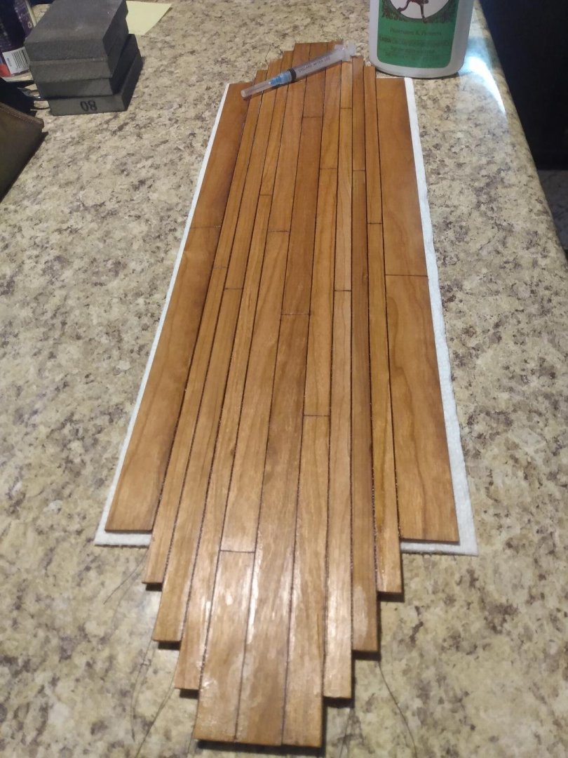
-
18th Century Iron nails
tmj replied to tmj's topic in Building, Framing, Planking and plating a ships hull and deck
Something just caught my eye on the Philidelphia. This post 'does' concern that boat! Looking at the Smithsonian's online 3D scan of the Philidelphia's sides... those nails are 'not' square headed nails! They are flat 'Cut' nails! Take a look at the Smithsonian's 3D model. The nail heads are elongated/rectangular running in a fore/aft direction, with the grain of the wood. That is exactly the proper orientation of a correctly placed 'Cut' nail! "Hmm? I can't believe that I missed this up until now, but I did! This new observation may have just made my "Make it or Fake it" job a whole lot easier! -
18th Century Iron nails
tmj replied to tmj's topic in Building, Framing, Planking and plating a ships hull and deck
Hi Chuck! This thread isn't targeting the Philidelphia. It's a general question. While poking around 'somewhere', I stumbled upon something (can't remember what/where) that made brief mention of iron nails being dipped in tar, or pitch to better seal things up. I'm just trying to find out if such a thing was ever truly done, or maybe just done on a particular vessel or few. Sounds like a lot of extra messy work to me, with little benefit. Learning a bit more about ships fastenings is something that I need to do, in general. As for the Philidelphia, I'm currently trying to figure out a way to either make, or 'fake' square headed nails at proper scale dimensions. At 1:24 scale, the square heads will be noticeable. I have a couple of ideas but haven't tried any of them yet. -
18th Century Iron nails
tmj replied to tmj's topic in Building, Framing, Planking and plating a ships hull and deck
I was actually raised in Midland (Texas), hot and dry as a bone. Didn't feel bad at all. I left Midland for the Navy in 1979. I've now been living in Dallas for 14 years. Dallas is nothing like Midland, Texas. It's so hot and humid here in Dallas... Michigan sounds pretty darned good to me too! -
18th Century Iron nails
tmj replied to tmj's topic in Building, Framing, Planking and plating a ships hull and deck
I decided to purchase the 'Kindle' version. While I typically prefer hard copies of books, my bookshelves are now all overloaded because of that desire. I have books lying flat atop of 'other' books that are properly standing upright in my bookcases. Old age and a lifetime of collecting has finally caught up with me. I'm now forced to join the 'digital' age in order to keep collecting books *sigh*. That's okay, I guess, as information is just that no matter what form it comes in... but I'm having a hard time accepting it. A hard copy book has tangible physical characteristics, a nice-looking cover, pages that one can slip a bookmark in between... and also a distinct 'smell' that I find to grow more and more pleasant as a book continues to age. Computer books have none of that kind of character. They are nothing but electron blips on a plastic screen! 😔 I'll give it a review, of sorts, once I've gone over its content. -
18th Century Iron nails
tmj replied to tmj's topic in Building, Framing, Planking and plating a ships hull and deck
That's the way that I read it also, however. I'm also really interested in reading what is mentioned on all those missing pages. -
18th Century Iron nails
tmj replied to tmj's topic in Building, Framing, Planking and plating a ships hull and deck
Got it Keith! The missing pages trap was well baited... and I think I'll bite. Should be very informative in its entirety. -
18th Century Iron nails
tmj replied to tmj's topic in Building, Framing, Planking and plating a ships hull and deck
There are pages skipped in the link that you gave me. Is there a reason for that? I've added this book to my Amazon shopping cart and will pull the trigger on it if it is a 'complete' and worthy read. -
Ahoy, mates...from central California
tmj replied to Capt. Kenway's topic in New member Introductions
Greetings and enjoy this forum! -
Gunboat Philadelphia 1776 by tmj
tmj replied to tmj's topic in - Build logs for subjects built 1751 - 1800
Bottom planks/strakes have now been glued up and the 'Oakum' caulking has been hammered into the caulking seams. Next up... I need to better seal those oakum caulking seams with a proper topcoat 'bead' of 'pitch'.... stay tuned!
-
Has anyone ever heard of 18th century iron nails being dipped into tar, or pitch prior to being 'driven-in' for purposes of corrosion/rust control... as well as additional water-tight integrity of a ship's hull?
-
Gunboat Philadelphia 1776 by tmj
tmj replied to tmj's topic in - Build logs for subjects built 1751 - 1800
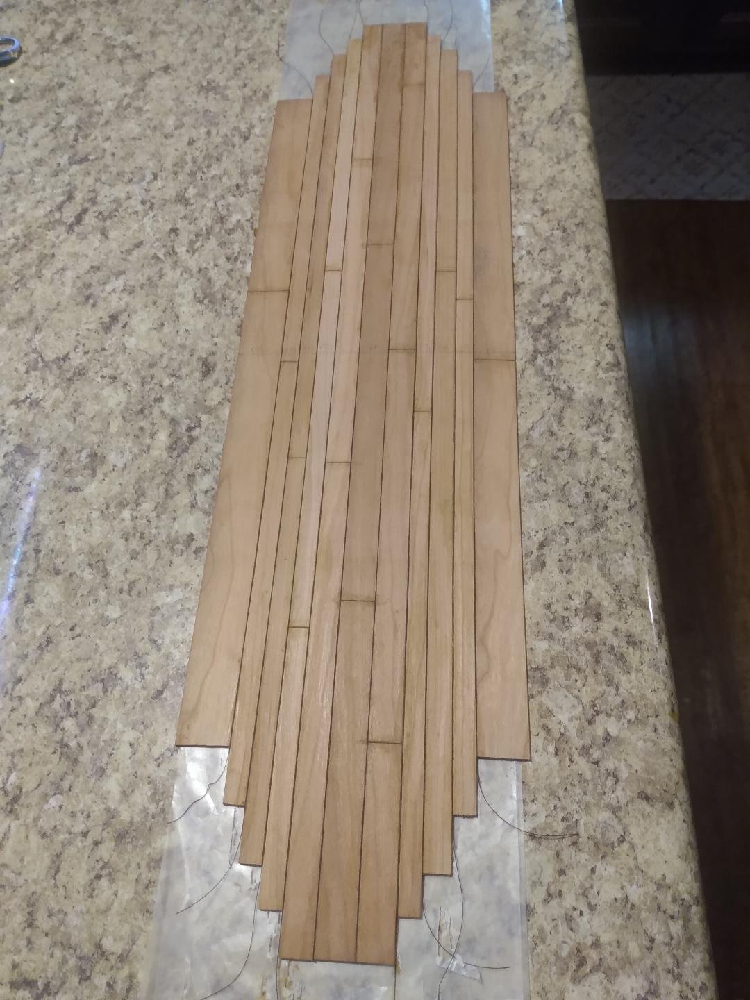
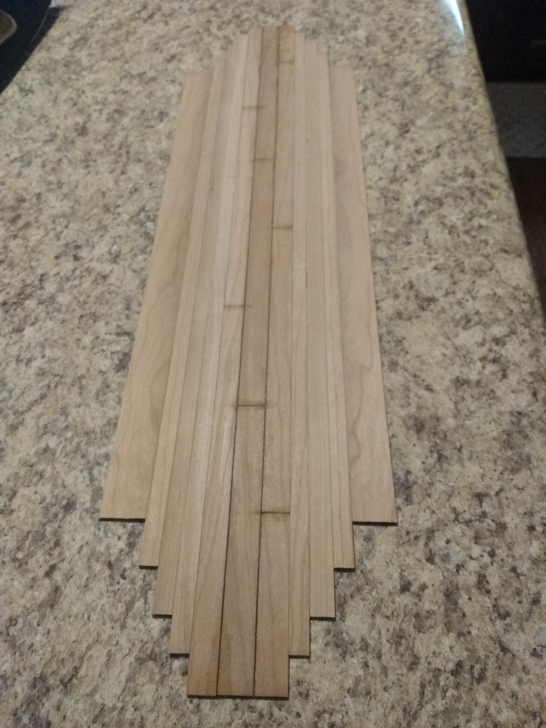
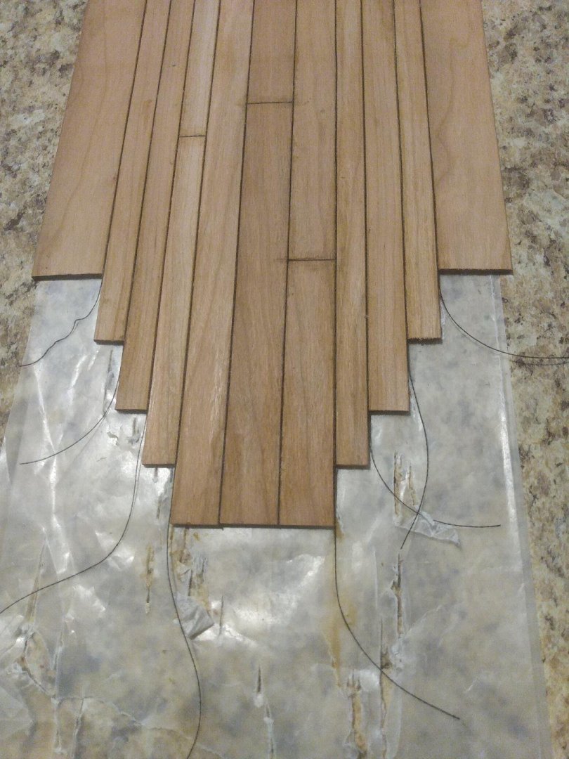
It's been a slow go this week. I was hoping to have made more progress but have only managed to get this far. "Best laid plans", you know... Anyway. The Strakes are all cut to length, and I still need to add the 'butt-joints', glue the strakes together and add the caulking to the bottom side of this 'bottom' planking. I'm really anxious to get this bottom completed and the shape cut out so I can move on to more interesting things in this build. Fingers are crossed in hopes of a more productive weekend... ** Notice the varying widths of all of the bottom strakes. No two strakes are the same. This is not me screwing up. This is per dimensions taken off of the actual vessel. There's no consistency in the width(s) of the materials that were used to construct the bottom of this boat. **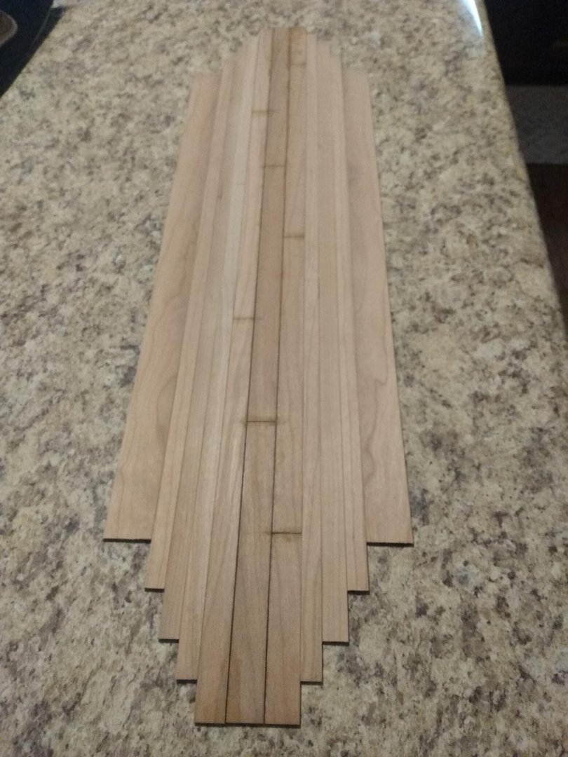
-
Freewing B-2 Spirit Bomber by tmj - Twin 70mm EDF Jet
tmj replied to tmj's topic in Non-ship/categorised builds
I wasn't planning on detailing the actual 'setup' of this thing, as it is quite different than any 'typical' R/C model... but I might if there is enough interest. -
Freewing B-2 Spirit Bomber by tmj - Twin 70mm EDF Jet
tmj replied to tmj's topic in Non-ship/categorised builds
86.6", almost 7.25 feet -
A new toy. It's going to take me a while to properly set this thing up and get it ready for its maiden flight, but that's okay. Summer has arrived in Dallas and it's just too darned hot to play outdoors now. I should have it ready by fall, when it's a bit more comfortable to be outdoors. Yes, the cat could fit, but the Mrs. has already caught me eyeballing Lulu and has sternly warned me against trying to give her a commission and a flight suit! What can I say? The Admiral has spoken and I must follow orders...

- 4 replies
-
- 17
-

-

-

-
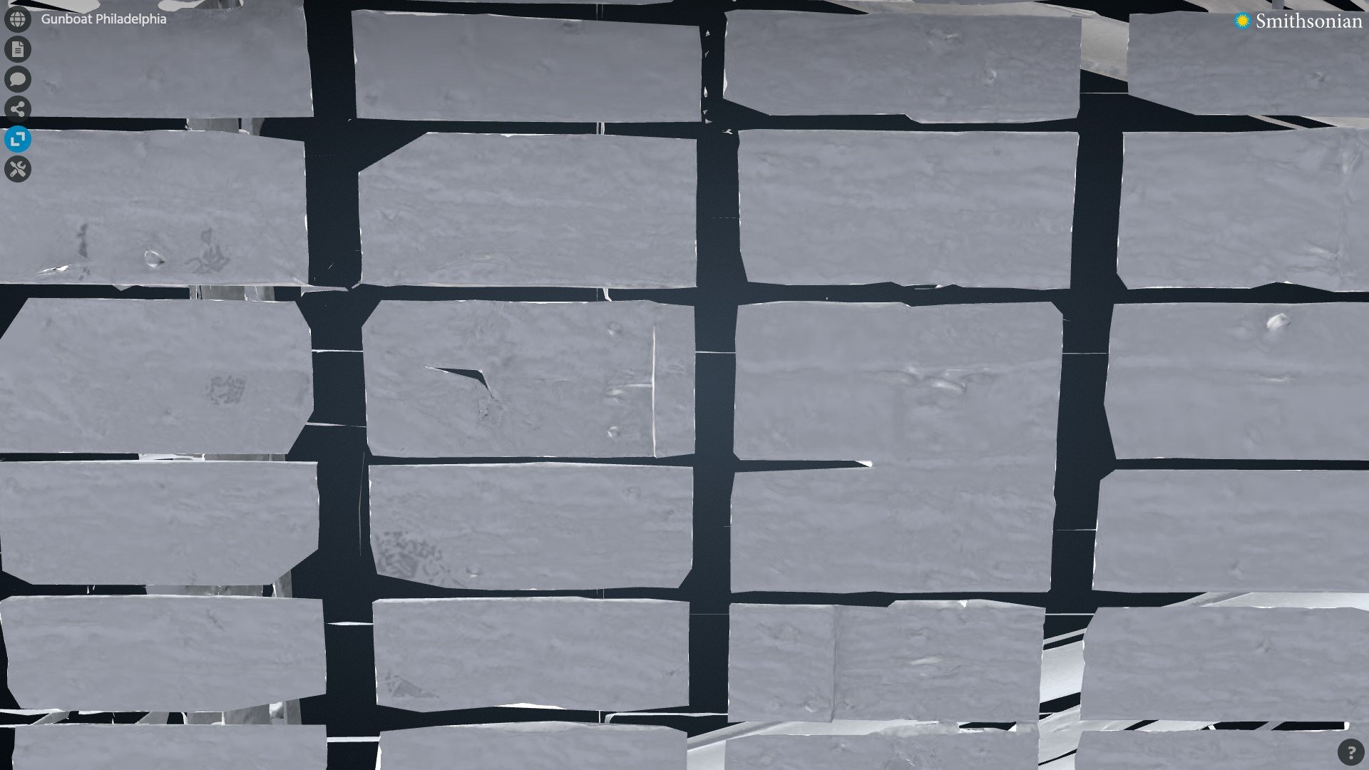
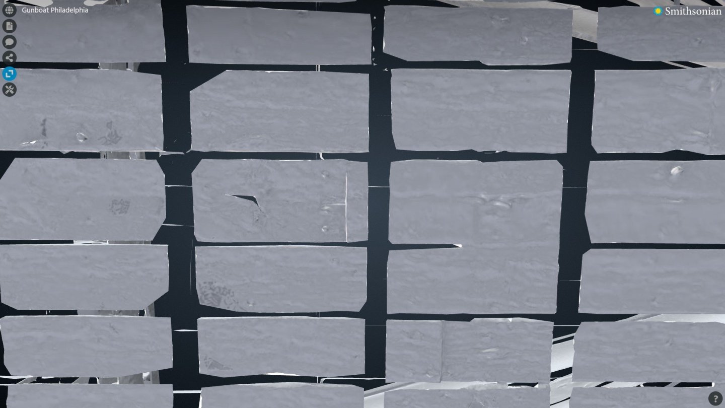
Here's that noticeable 'seam' on the aft section of the center bottom strake. Looks like nails there too, however. What about the floor timber just to the left of that seam. There are no noticeable fasteners in that area. There are actually very few to absolutely NO 'noticeable' fasteners shown on the 3D thing, of the bottom of the Philadelphia, as per Smithsonian's online 3D 'thingy'. Hmm, this is becoming even more curious... Perhaps the bottom 'was' tree nailed to the flooring timbers. If so, why the nails in this one isolated area and nowhere else? If you look at the second strake below the center strake, a bit to the right, you will see 'another' seam, but no pronounced indication of nails. I still haven't had the time to study my drawings. Work keeps getting in the way, but I will! Image courtesy of the Smithsonian Institution... online 3D viewing tool.
-
Yep, those certainly look like nails! Thanks!
-
Thanks Phil! I was thinking that it was probably this way, but then I started wondering about the expansion of the 'hull' after a new ship was launched and the hull got wet... and then I began to wonder if that expansion could actually 'break' things if not given some room to expand within. Wooden ship's hulls don't have metal bands around them, to hold them together and tighten things up like wooden barrels with metal bands have. The hull timbers that are in direct contact with the water will obviously expand more than the drier parts of the ship (frames) that are mainly only exposed to humidity and will not swell as much. Strakes of hull planking swelling a lot, that are fastened to frames that aren't swelling as much = a lot of stress on both the strakes as well as the frames and definitely the trunnels! I'm sure that you see where I'm going with this. It has nothing to do with building models, but real-life things like this fascinate me. I guess I just like to know how and 'why' things work whether it really matters to me, or not! I've been asking "How and Why" for 63 years. No reason to stop now! 🙂
-
Hello Chuck! I'm going to dig a bit deeper into this. As per John Bratten's book, the bottom planking was 'temporarily' "toe-nailed" to the flooring timbers until trunnels were successfully installed... then the iron toenails were removed. It was only the dry parts of the boat that incorporated iron nails. If this is true, then it only makes since that there would also be 'trunnels' on the sides, below the water line. "Hmm?" I'll study my Smithsonian drawings closely before securing the bottom planking to the flooring timbers. I'm sure that there is some needful info there that I have not looked at yet. I've so far only worked on the dimensions, not the fastening details. For whatever it's worth. I've already found a conflict between John Bratten and my Smithsonian drawings. Bratten claims that the center strake, of the bottom planking, was a full-length strake running the entire length of the boat without any butt-joints. The Smithsonian drawings show differently. The drawings show TWO seams in that center strake! When looking at the online 3D thing from Smithsonian, I can see one 'obvious' seam in that center strake, towards the stern. The stem section is missing a lot of detail and it's hard to tell if a second seam is hiding there, but it probably is. If Bratten was wrong about the makeup of that center strake... he could easily be wrong about the trunnels too!
-
Gunboat Philadelphia 1776 by tmj
tmj replied to tmj's topic in - Build logs for subjects built 1751 - 1800
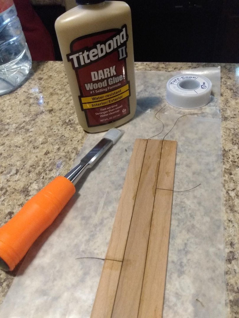
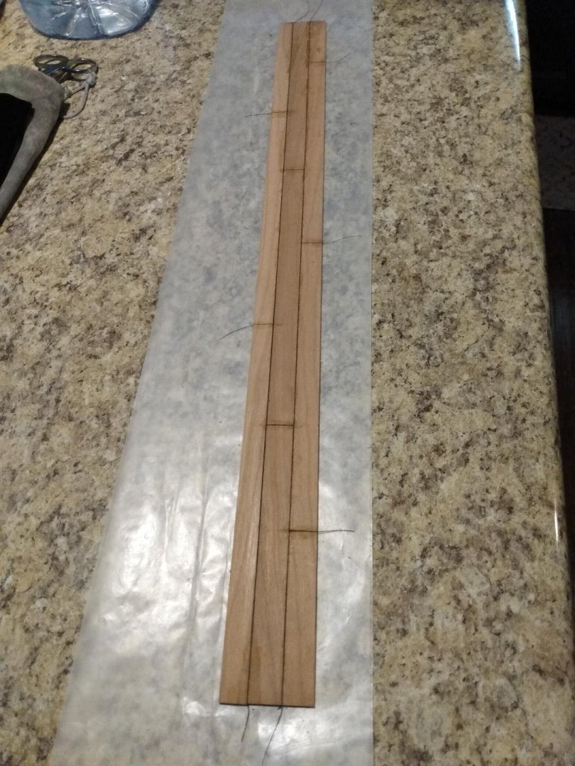
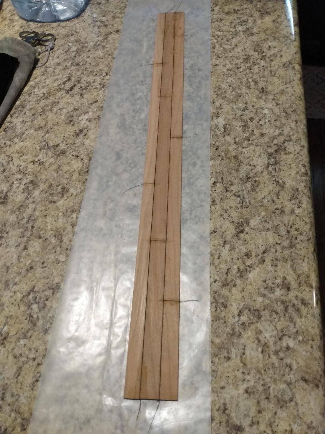
Beginning the bottom planking and caulking. I'm starting from the center of the bottom and working my way 'outwards'. The bottom is being assembled 'upside-down' (unlike the 'real' building method of this vessel). I'll add two strakes every day until the oversized bottom blank is completed and caulked, then I'll cut out the shape of the bottom. I'll only do two strakes per day because I'm trying to avoid any distortion and/or warpage due to the long joints and glue runs. I'll be gluing the new strakes to an already glued up 'sub-assembly' that has cured and is rather stiff. The strakes are full length. I'm adding the illusion of 'planks' within those strakes via a chisel. The 'caulking' is .0078" diameter "Tuff-Cord" that would represent a 3/16" caulking seam on the full-sized vessel. I lightly sanded the edges of all the strakes to form the tiny groove needed to accept the tuff-cord. To insert the caulking, I run the thread through a puddle of glue, lay it in place at the start of a groove and just run my finger down the thread's length. The thread pretty much finds the grooves all by itself. I then give it a wipe with a paper towel, to remove excess glue, and let everything dry. The tag ends are cut after drying. The caulking is fairly secure once the glue dries, but it will also be sealed in permanently with a clear topcoat after the bottom is completed and finish sanded, prior to cutting out the shape of the bottom.