tmj
-
Posts
774 -
Joined
-
Last visited
Content Type
Profiles
Forums
Gallery
Events
Everything posted by tmj
-
 When the bulkheads are 'fared', prior to planking the model, that faring operation should effectively remove all of that char. You 'can' sand away that char, prior to gluing the bulkheads in place, but take care. You must be very careful and sand with fine paper using a very light touch. If you sand too hard it will leave low spots in the areas of those bulkheads that were sanded harder than in other areas. This will make your planks wavey, in and out, and just plain bad looking in the long run, requiring filler, sanding and laying down a 'second 'decorative layer of planking to hide all of the filler, unless you plan to fill, sand and paint the hull without any planking details showing through to the surface after painting. It's your choice, but no real reason to sand that char prior to faring.
 -
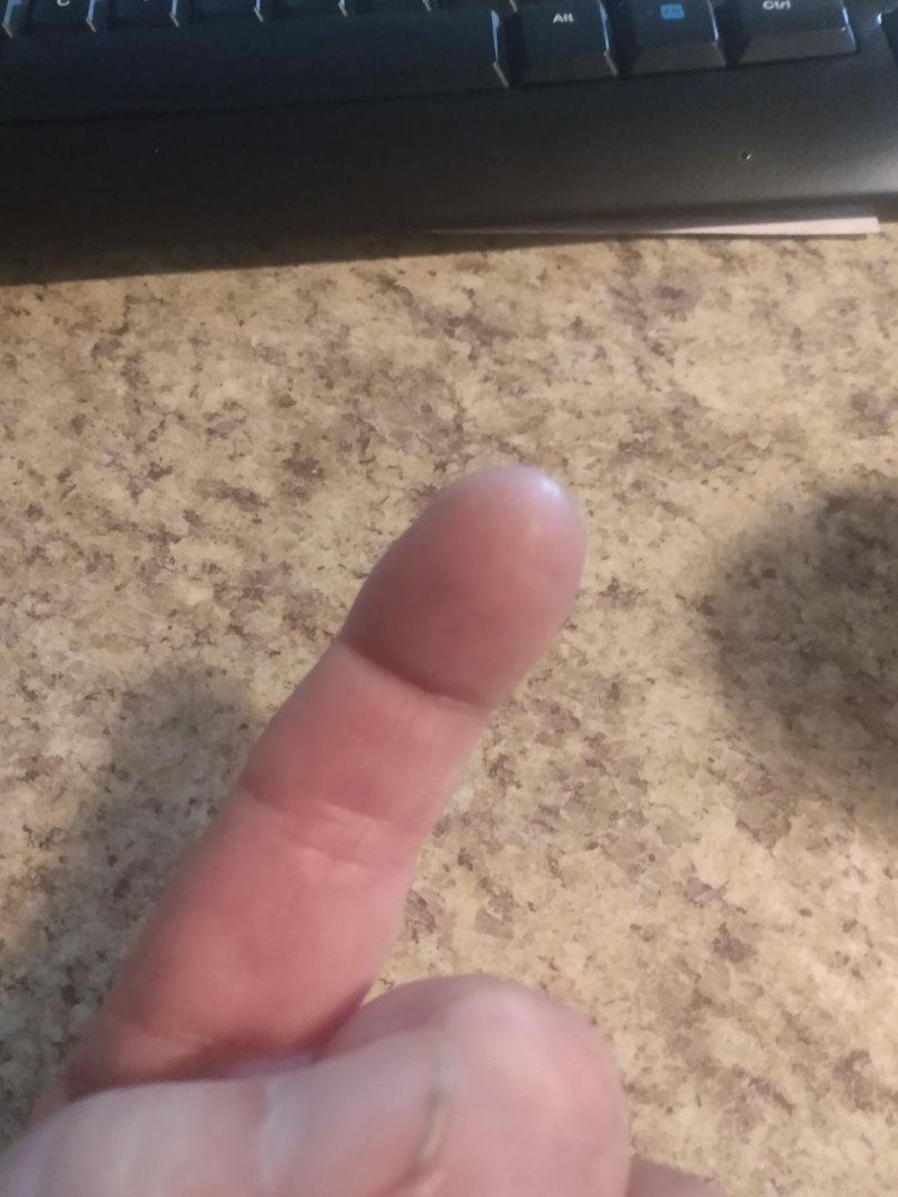
I probably have a thousand of those things and they work great for applying the CA, but when it comes time to 'smear' thick coats of CA around, for good and even coverage... nothing beats 'this'! "Just don't ever pause in the smearing process, not even for a split second until the ol' finger has been lifted off of the wood!" I don't need to tell anyone 'Why' they should not stop moving that finger. That's a bit obvious! Believe it or not, the cured CA actually peels off of my fingers rather easily if allowed to sit long enough for natural body/finger oils to soak in and release the thick CA cap from my fingertip(s). One, maybe two hours. Don't do this if you still have any delicate work to perform right away. Do this last. Until I peel that CA cap off on my fingers, I find it impossible to pick my nose or even accurately scratch my *ss. I wouldn't want to even attempt to handle any small parts immediately afterwards! Notice how smooth and finger-print free my fingertip is! 😏
- 146 replies
-
- 8
-

-

-
- Speeljacht
- Seahorse
- (and 2 more)
-
What Bob asked... "I'm curious too!"
-
How did you apply the thin CA? I typically smear CA finishes onto certain projects using my bare fingers, never stopping while smearing... then spend the next few hours defoliating my fingers while peeling off the cured CA layer. There 'must' be a better way!
- 146 replies
-
- 4
-
-
- Speeljacht
- Seahorse
- (and 2 more)
-
Looking at that photo... "are you 'sure' that is a steam donkey and not 'actually' an illegal still about to start giving up its nectar to a bunch of very thirsty loggers?"
-
Now "THAT's" what I'm talking about! "Beautiful work, beautiful display! It can't get any better than 'this' unless Model Trailways starts putting real hair on their horses!
-
I often use oily exotic wood veneers on the face of guitar headstocks. I clean those veneers with mineral spirits prior to gluing them on, for good adhesion, however. When I finish the product, usually with 'Tru Oil', that iridescence typically returns. The deeper the finish, the more iridescent the wood becomes. I really like that on my guitars, but not so much on my ship models. Pfalzer is 'also' correct. I've noticed that the grain orientation 'does' effect how the wood veneer looks. Before cutting my patterns, I like to dampen the wood, just a bit, to get an idea of how it will look once applied. I then look at it from different angles of light to determine if I like it one way, or like it better when flipped 180 degrees. Orientation 'does' matter! Perhaps sealing the iridescent wood with a good finish, for protection... then dulling it down with some 400-800 grit sandpaper followed by a light smear of Danish oil, to bring the wood back to life, would remove that iridescent irritant? Don't know. I've never tried that, but it might be worth an experiment or few...
-
Help with tapering
tmj replied to N1ckel's topic in Building, Framing, Planking and plating a ships hull and deck
You really do need to taper your planks, in most situations, to produce a first-rate build. It's not that difficult. Below is part one of Chuck Passaro's four-part series of planking hulls, found on his YouTube channel. Watch all four parts and then enjoy planking your model! -
Congratulations! That's a very fine specimen of a quality model ship! So... "what's next?"
- 562 replies
-
- 3
-

-
-
- vanguard models
- alert
- (and 2 more)
-
Very nice work! Are you going to spring for a team of horses to go with this coach and your Doctor's Buggy? That would look really, really 'sweet'!
-
Sapele is indeed a rather 'rich' looking color of wood. If you are not happy with that color/tint there is little that you can do about it, unless you want it darker, then you can simply stain it. Your best bet, should you be seeking a 'lighter' shade would be to purchase, or cut your own planking strips using a lighter-colored species of wood... and then experiment with stains, finishes, etc. until you achieve the shade/color that you truly desire. If you are talking about those really, really 'thin' strips that come with some kits, to be placed over 'thicker 'first' planks... you might need to shop eBay for thin veneers and cut the strips yourself using a hobby knife and a metal straight edge. You'll find a lot of nice looking and thin veneers on eBay.
-
Intro and interests, from a beginner
tmj replied to Desert_Deckhand's topic in New member Introductions
I was born in Big Spring, Texas and raised in a desert (much like your current location). When I left the desert, for the Navy, I swore that I'd never live far from water ever again. I've stuck to that promise! Perhaps being raised in the desert is what first drew me to the Navy... and now to model ship building! Welcome aboard! -
Looking good and coming along nicely! This is going to be an interesting build to say the least! I'll be keeping a close eye on this one... 🙂
-
Very fine craftsmanship, indeed! I'm a late comer to your build log but really enjoy your style of building. A very pleasant combination of aesthetics, artform and skill!
- 201 replies
-
- 5
-
-
-
- Oyster Sharpie
- first scratch build
- (and 1 more)
-
Are those electric plank benders worth it?
tmj replied to Spaceman Spiff's topic in Modeling tools and Workshop Equipment
The trick to bending wood with few failures is to 'compression' bend it by tightly trapping the ends of what is to be bent within a thin metal, or leather 'backing strap' before bending. Wood fibers do not stretch, they 'tear' if you try to stretch them. That tearing is what lifts splinters and causes ugly cracks and failures. Go to YouTube and search for "Engels Coach Shop" and search his site for steam bending woods. He works with large timbers, in full scale. He's not a modeler... but the bending principles are the same for any sized timbers, even our small models! You might also want to look into violin making, on YouTube. Violin makers use the same principles of bending thin wood, and they typically don't use steam at all, only heat from great big ol' soldering irons used by old time roofers for soldering vents and other large sheet metal items. Bear in mind that heat is what most effectively bends woods. When wood is steamed, it is 'not' the water that softens the lignin's of the wood, making it pliable. It is the heat! The water in steam is simply an efficient and excellent 'carrier' of that needful heat! -
Gunboat Philadelphia 1776 by tmj
tmj replied to tmj's topic in - Build logs for subjects built 1751 - 1800
A Byrne's saw just sold on eBay, last week I think, for over $4K. Another one showed up right after that first auction ended with 'Its' starting price being $1,200, much like the first auction. I'm really, really suspicious about that curious activity and also the timing. I'm not so sure that those auctions were truly 'legitimate'. I have a gut feeling that those two auctions were being put on by illegitimate individuals running shill games, scams, etc. trying to run the 'expected value' of these saws up to ridiculous levels, of which those saws are not truly being sold for, right now. It just looks that way! This sets a very bad potential precedence for future auctions of Byrne's equipment be it by both legitimate folks, as well as illegitimate and manipulative price gougers. I wouldn't buy a Byrne's saw for that much money unless it came with digital read-outs and a CNC upgrade! Call me crazy, call me 'wacky'... I just smell something 💩funny about those two auctions... -
Gunboat Philadelphia 1776 by tmj
tmj replied to tmj's topic in - Build logs for subjects built 1751 - 1800
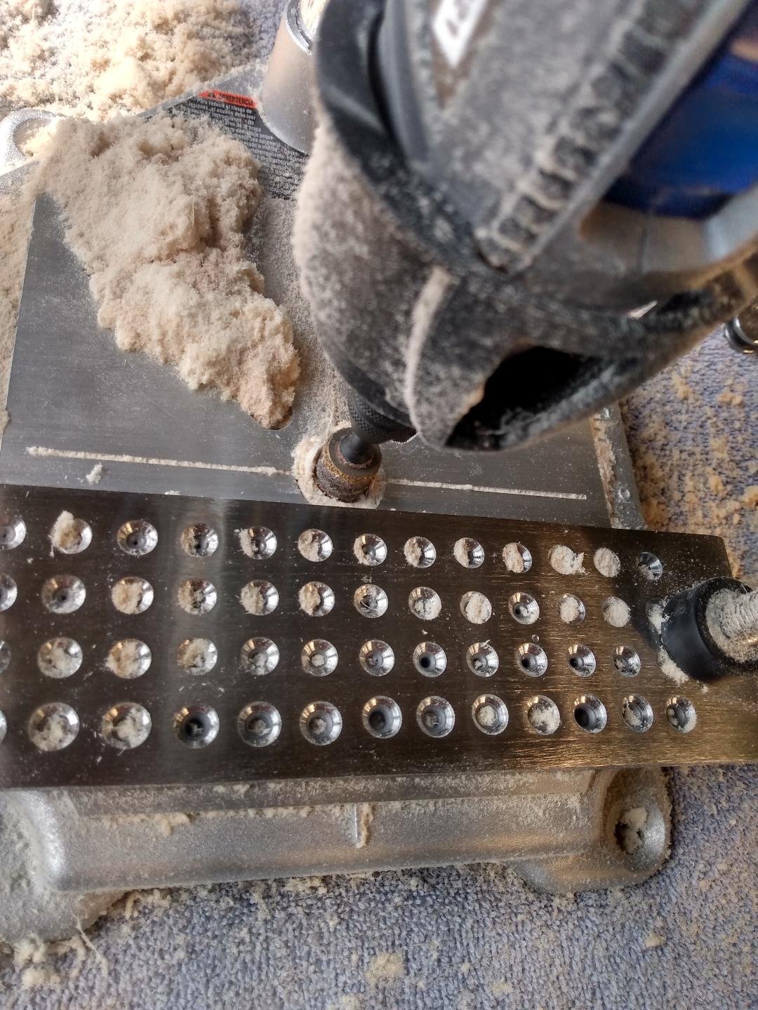
In case anyone is curious, 'this' is the cheap Amazon saw that I used to cut the limber holes. It comes with a small fine-tooth blade that works really well on small part details. Nothing to write home about, but it works well if properly used. Just don't expect too much from this. It's 'not' an all-purpose workhorse! I'm not trying to promote any products. I'm just letting folks know that while expensive, high-quality equipment is very nice... it's also not absolutely necessary. Learn the limits and the idiosyncrasies of cheap stuff like this and you too will quickly figure out how to overcome all of the short comings and be able to produce some rather accurate work. Everything has its "Ticks and Tricks"... even the expensive stuff!
-
Gunboat Philadelphia 1776 by tmj
tmj replied to tmj's topic in - Build logs for subjects built 1751 - 1800
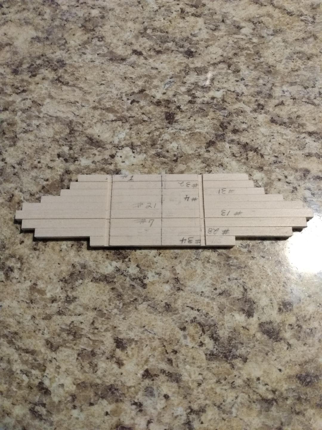
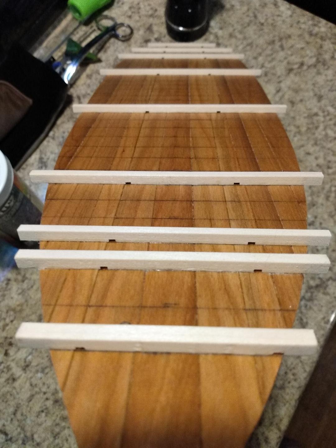
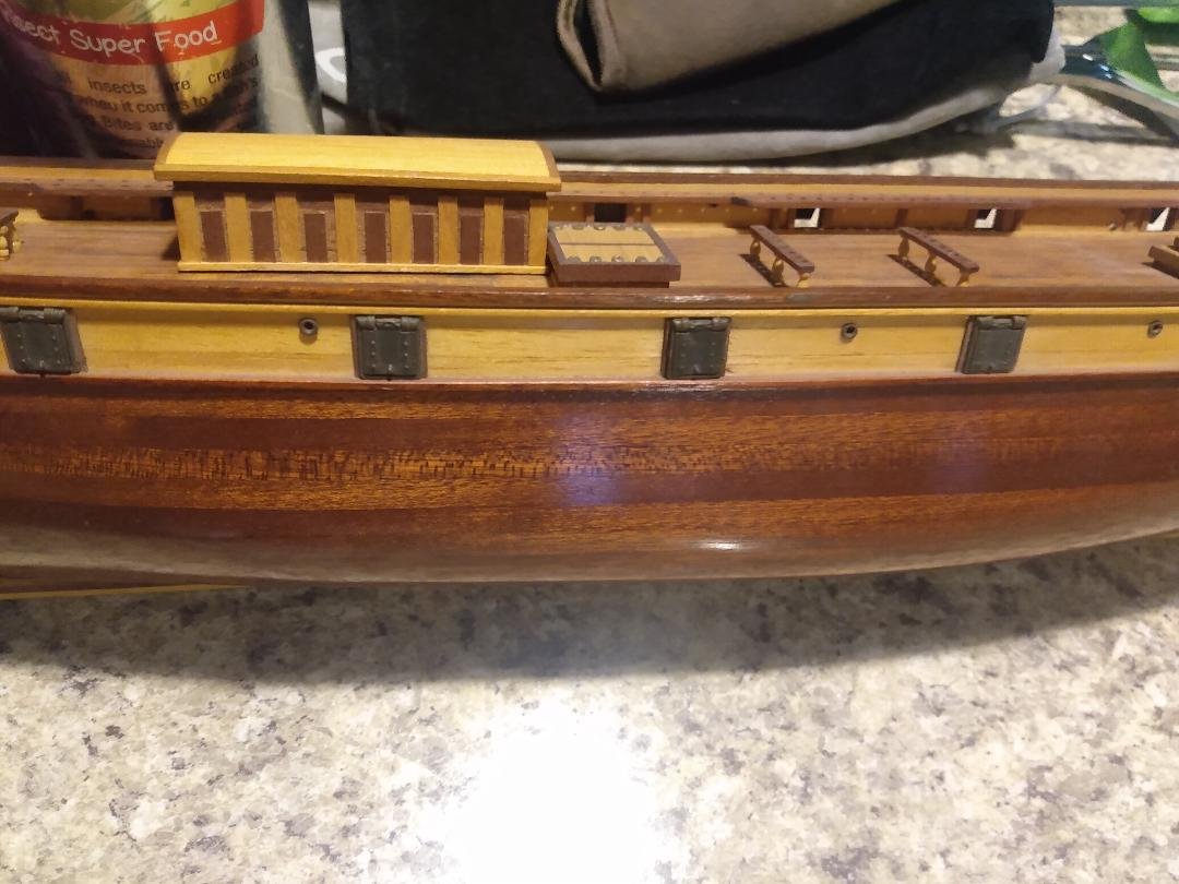
First 9 of 34 flooring timbers have been fabricated and glued in place. Odd locations, I know. I wanted to brace the bottom planking, from port to starboard, to prevent warpage while also getting the best yield from my material. Bottom planking is now well braced, so I'll be able to fill in the gaps with a more 'balanced' sequence of flooring timbers (provided that yield doesn't dictate otherwise). Milling the widths of these flooring timbers wasn't nearly as difficult, nor time consuming as I thought it was going to be. The job went rather quickly, and accuracy was easily held to within .002" of my desired widths, prior to sanding them smooth with 220 grit paper. After sanding, they are now pretty close to being dimensionally 'perfect'! "Who says that cheap tools from Amazon can't produce accurate results!" "They 'CAN'!" I laid out the centerline of each timber and taped all of the timbers together using blue painter's tape... then marked out the locations and dimensions for the limber holes. I cut the limber holes using yet 'another' cheap table saw from Amazon with a small diameter, fine tooth blade. I cut the limber holes while all of the flooring timbers were taped together. Worked 'great'! Here's a photo showing the installed flooring timbers with their limber holes. 9 flooring timbers down, 25 to go!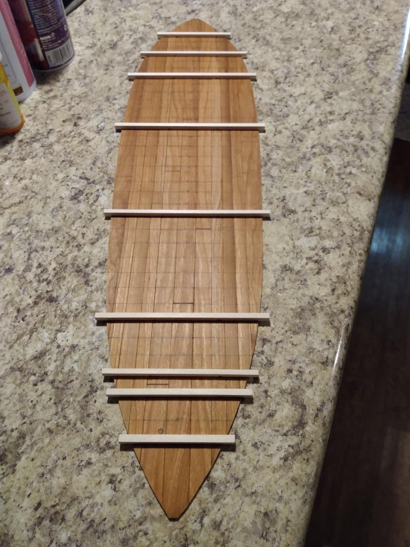


-
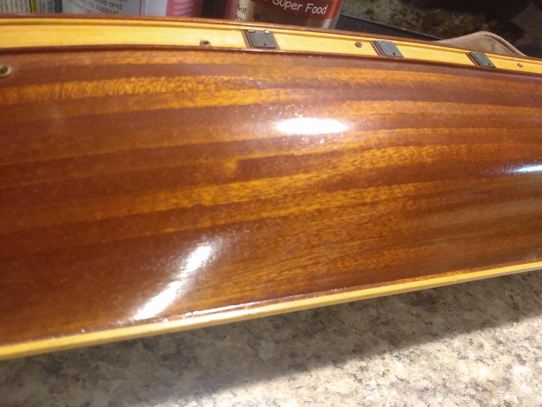
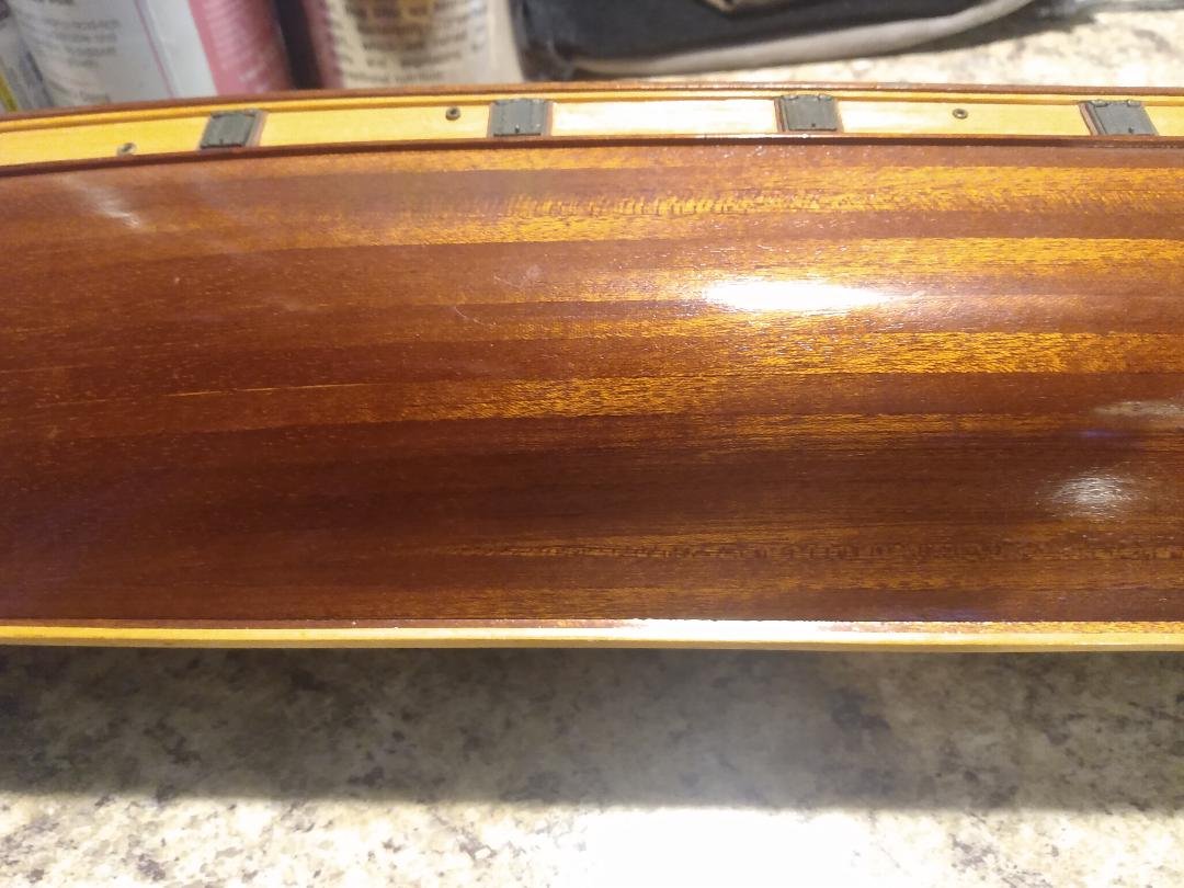
Take a deep breath and relax. All is actually good... despite what you currently think! You 'can' fix this! #1... As Stevinne mentioned, you do 'not' need a rabbet. Just bevel your plank to an angle that will hug the keel. #2... Water does not bend wood. 'Heat' bends wood. Remember this! Steam is a mixture of water and steam, but it is 'still' the heat that is bending the steamed wood, not the water. The water, in steam, is simply a very good carrier of that heat! No need to soak your planks. Bend them with 'heat' prior to putting them on your hull. Use glass jars, metal cans, whatever as forms to bend upon. Get the bends close and then let your clamps and glue do the rest. #3... Bevel the edges of all planks so there will be no unsightly gaps after being bent and glued in place, unless you want to simulate caulking. Even then, you'll still need to bevel your planks to reduce the size of your caulking seam. You might need to purchase some new planking material to perform the repair, but you should have no trouble finding that material being readily available through wood sources listed on this forum, or maybe in hobby shops where you live. Below is a Cutty Sark of mine, still under construction. The hull planks are between 1.5mm and 2mm thick. You will notice two things. #1, there are no gaps between the planks. That's because I beveled them before heat bending them around jars, cans, whatever objects around me that looked to have a usable shape. #2, take a look at the keel. There is no rabbet cut into that keel. Once again, I simply beveled the plank, with sandpaper to make it hug the keel. For 'that' plank, I did the beveling 'after' the plank was bent, due to the complex geometry involved. Sand, fit, sand some more, check fit, sand, fit, sand, fit... yadda, yadda, yadda. I used CA glue to attach these planks to the bulkheads. You can do this, just relax, think it through and remember to bend those planks, with heat, 'before' trying to attach them to the hull's bulkheads! "Don't give up the ship!"
-
From what I've read... thibaultron is mostly correct. Galleons of that era were oft times elaborately decorated with gold and/or 'gilt' finishes for the purpose of displaying wealth, power, and the status of the ship's owners, country, etc. That being said, and for whatever it's worth... the Atocha has yet to give up any valuable artifacts from any stern decorations. If there was any heavy gold there it would have been found. Odds are that any gold decoration/glitter of sternpost decoration, on the Atocha, was gilded and quickly claimed by the sea via time and degradation... if it existed at all.
-
Gunboat Philadelphia 1776 by tmj
tmj replied to tmj's topic in - Build logs for subjects built 1751 - 1800
The 'Redneck' thickness mill works pretty darn good, for what it is. I used my Dremel workstation, two 'C' clamps and a drawplate for the front gauge. The tool is a 1/2" Dremel Carbide sanding drum @ 60 grit. I'm currently about .001" proud of my desired thickness in height, but after smoothing over the milled side with 120 grit paper I should be spot on. Cuts were made shallow, about .020" max per pass. If I tried to hog any more meat off than .020", I'd have to slow down and the wood would start to burn, as well as my finger! The Dremel shaft flexes a little when hogging off those heavier cuts, so I just kept running the timbers through until the shaft was finally relaxed and not cutting anymore, about three passes p/piece. The final finish passes were only a couple thousandths deep so there was no flexing of the shaft. Now that I have the height set for all of my flooring timber material... it's time to start milling the widths of those timbers, cutting them to their proper lengths, as described in a previous post, and cut out the limber channels prior to gluing those flooring timbers in place atop the bottom planking.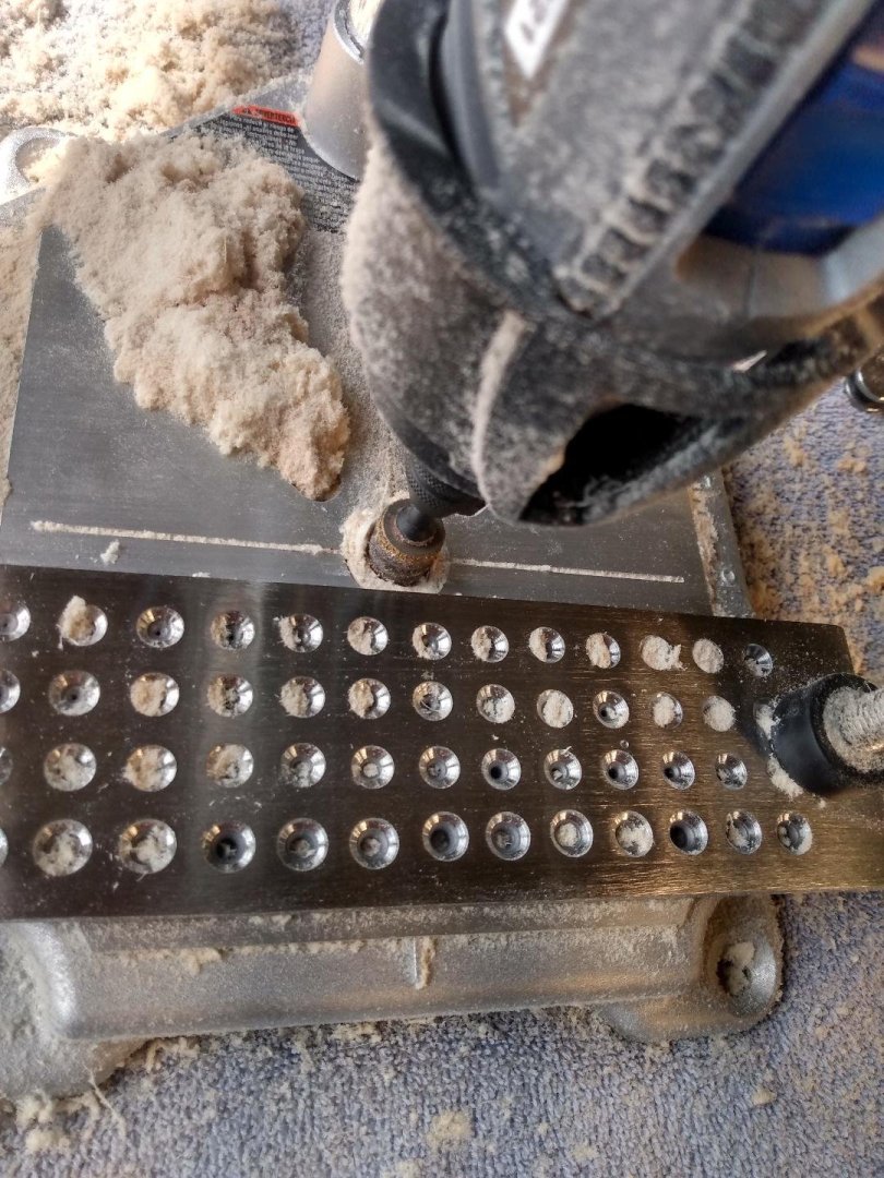
-
Gunboat Philadelphia 1776 by tmj
tmj replied to tmj's topic in - Build logs for subjects built 1751 - 1800
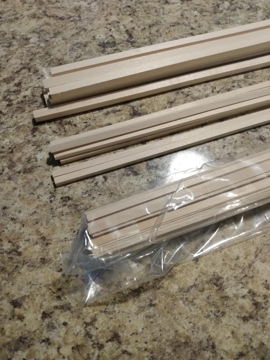
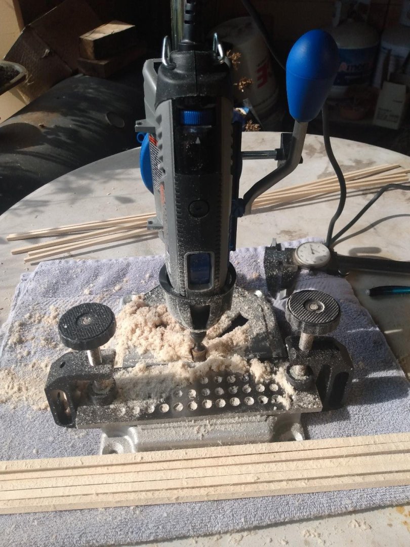
A new load of wood just arrived. Not a big haul, just enough material to continue with my build at its current stage. The 3/16" and 1/4" square pieces are what will become my flooring timbers after being milled down to proper dimensions. The plastic bagged 1/32" X 3/16" strips are for a different part of this build, to be addressed later. I've fallen behind on my 'ad hock' milling setup for the flooring timbers (day job keeps getting in the way of things) but hope to make up for that lost time tomorrow. I'm hoping to have some flooring timbers milled and ready for installation no later than Sunday evening. "Fingers are crossed!" I won't be able to 'treenail' any of the flooring timbers to the bottom decking, even if I get the timbers milled this weekend, because my #58 drill bits have now been delayed, in delivery, and not expected to arrive until Monday. No biggie. I think I have my hands full right now with what I have before me.
-
First timer introduction and needing some advice
tmj replied to Stuka's topic in New member Introductions
This is great advice! Just because a certain kit has a lot of appeal, comes with great instructions and is made from the highest quality of parts doesn't mean that it should be ones 'first' build! Lots of folks get started in this hobby without first understanding and/or considering the true commitment required, the discipline and the amount of time involved... as well as the processes and skills required to successfully construct even a simple 'fine' model ship. Lots of folks start out thinking 'fancy', with good intent, only to later run into problems and wind up putting their unfinished model(s) on the shelf. This happens to newbies as well as experienced folks. I'm a prime example of that! "Stuff happens to folks at 'ALL' levels of experience!" As mtaylor recommended, perhaps you should start out with Model Shipways 3 ship beginner package. This will let you know if you want to shell out the bigger bucks for fancier, more complex ship models. The added bonus is that you will also be building your confidence while constructing these three beginner models. Even if they don't turn out to be museum quality, they will still look great and be things to be proud of! If you do not lose interest while building these beginner models, while also advancing your skills in ship modeling... "Then it will be time to consider going to the next level with more expensive and more detailed kits... or even scratch building from plans." Start easy. Make sure that you truly want to do this. It's a great hobby! Don't start off on the wrong foot and wind up regretting it! -
I might 'still' be getting this wrong, but if my interpretation of your question is actually correct this time... I'd start with cutting out a wooden, or paper pattern to the exact dimensions and shape of the desired gunport. I'd 'then' use a height gauge to set the proper location and level of that gunport and the pattern with the model sitting level and secure in a cradle, or some sort of a 'berth' that will securely hold the model level and not allow it to shift nor list from port to starboard. Lay out your gunport(s) with a fine point pencil, or better yet, an extremely fine knife slice for a mark. Next, cut temporary braces to fit snugly between the surrounding frames, to hold those frames secure while sawing/cutting those frame members and also filing in the rabbets for the horizontal header and footer components. Use a tiny drop of PVA glue to secure those temporary braces in place. Don't use CA. Keep everything proud and use files to get the proper fit(s) without creating any unsightly gaps. File, check fit, file, check fit. Once you have your gunports installed, and everything is securely glued up remove those temporary braces via a knife and some filing to clean up the glue residue. I hope that this helps...